US7522186B2 - Method and apparatus for providing immersive surveillance - Google Patents
Method and apparatus for providing immersive surveillanceDownload PDFInfo
- Publication number
- US7522186B2 US7522186B2US10/202,546US20254602AUS7522186B2US 7522186 B2US7522186 B2US 7522186B2US 20254602 AUS20254602 AUS 20254602AUS 7522186 B2US7522186 B2US 7522186B2
- Authority
- US
- United States
- Prior art keywords
- model
- video
- scene
- view
- images
- Prior art date
- Legal status (The legal status is an assumption and is not a legal conclusion. Google has not performed a legal analysis and makes no representation as to the accuracy of the status listed.)
- Expired - Fee Related, expires
Links
Images


Classifications
- G—PHYSICS
- G06—COMPUTING OR CALCULATING; COUNTING
- G06T—IMAGE DATA PROCESSING OR GENERATION, IN GENERAL
- G06T15/00—3D [Three Dimensional] image rendering
- G06T15/10—Geometric effects
- G06T15/20—Perspective computation
- G06T15/205—Image-based rendering
- H—ELECTRICITY
- H04—ELECTRIC COMMUNICATION TECHNIQUE
- H04N—PICTORIAL COMMUNICATION, e.g. TELEVISION
- H04N7/00—Television systems
- H04N7/18—Closed-circuit television [CCTV] systems, i.e. systems in which the video signal is not broadcast
- G—PHYSICS
- G06—COMPUTING OR CALCULATING; COUNTING
- G06T—IMAGE DATA PROCESSING OR GENERATION, IN GENERAL
- G06T19/00—Manipulating 3D models or images for computer graphics
- G06T19/006—Mixed reality
- G—PHYSICS
- G06—COMPUTING OR CALCULATING; COUNTING
- G06T—IMAGE DATA PROCESSING OR GENERATION, IN GENERAL
- G06T7/00—Image analysis
- G06T7/20—Analysis of motion
- G06T7/246—Analysis of motion using feature-based methods, e.g. the tracking of corners or segments
- G06T7/251—Analysis of motion using feature-based methods, e.g. the tracking of corners or segments involving models
- G—PHYSICS
- G06—COMPUTING OR CALCULATING; COUNTING
- G06T—IMAGE DATA PROCESSING OR GENERATION, IN GENERAL
- G06T7/00—Image analysis
- G06T7/30—Determination of transform parameters for the alignment of images, i.e. image registration
- G—PHYSICS
- G06—COMPUTING OR CALCULATING; COUNTING
- G06T—IMAGE DATA PROCESSING OR GENERATION, IN GENERAL
- G06T7/00—Image analysis
- G06T7/50—Depth or shape recovery
- G—PHYSICS
- G08—SIGNALLING
- G08B—SIGNALLING OR CALLING SYSTEMS; ORDER TELEGRAPHS; ALARM SYSTEMS
- G08B13/00—Burglar, theft or intruder alarms
- G08B13/18—Actuation by interference with heat, light, or radiation of shorter wavelength; Actuation by intruding sources of heat, light, or radiation of shorter wavelength
- G08B13/189—Actuation by interference with heat, light, or radiation of shorter wavelength; Actuation by intruding sources of heat, light, or radiation of shorter wavelength using passive radiation detection systems
- G08B13/194—Actuation by interference with heat, light, or radiation of shorter wavelength; Actuation by intruding sources of heat, light, or radiation of shorter wavelength using passive radiation detection systems using image scanning and comparing systems
- G08B13/196—Actuation by interference with heat, light, or radiation of shorter wavelength; Actuation by intruding sources of heat, light, or radiation of shorter wavelength using passive radiation detection systems using image scanning and comparing systems using television cameras
- G08B13/19602—Image analysis to detect motion of the intruder, e.g. by frame subtraction
- G08B13/19608—Tracking movement of a target, e.g. by detecting an object predefined as a target, using target direction and or velocity to predict its new position
- G—PHYSICS
- G08—SIGNALLING
- G08B—SIGNALLING OR CALLING SYSTEMS; ORDER TELEGRAPHS; ALARM SYSTEMS
- G08B13/00—Burglar, theft or intruder alarms
- G08B13/18—Actuation by interference with heat, light, or radiation of shorter wavelength; Actuation by intruding sources of heat, light, or radiation of shorter wavelength
- G08B13/189—Actuation by interference with heat, light, or radiation of shorter wavelength; Actuation by intruding sources of heat, light, or radiation of shorter wavelength using passive radiation detection systems
- G08B13/194—Actuation by interference with heat, light, or radiation of shorter wavelength; Actuation by intruding sources of heat, light, or radiation of shorter wavelength using passive radiation detection systems using image scanning and comparing systems
- G08B13/196—Actuation by interference with heat, light, or radiation of shorter wavelength; Actuation by intruding sources of heat, light, or radiation of shorter wavelength using passive radiation detection systems using image scanning and comparing systems using television cameras
- G08B13/19639—Details of the system layout
- G08B13/19641—Multiple cameras having overlapping views on a single scene
- G—PHYSICS
- G08—SIGNALLING
- G08B—SIGNALLING OR CALLING SYSTEMS; ORDER TELEGRAPHS; ALARM SYSTEMS
- G08B13/00—Burglar, theft or intruder alarms
- G08B13/18—Actuation by interference with heat, light, or radiation of shorter wavelength; Actuation by intruding sources of heat, light, or radiation of shorter wavelength
- G08B13/189—Actuation by interference with heat, light, or radiation of shorter wavelength; Actuation by intruding sources of heat, light, or radiation of shorter wavelength using passive radiation detection systems
- G08B13/194—Actuation by interference with heat, light, or radiation of shorter wavelength; Actuation by intruding sources of heat, light, or radiation of shorter wavelength using passive radiation detection systems using image scanning and comparing systems
- G08B13/196—Actuation by interference with heat, light, or radiation of shorter wavelength; Actuation by intruding sources of heat, light, or radiation of shorter wavelength using passive radiation detection systems using image scanning and comparing systems using television cameras
- G08B13/19678—User interface
- G08B13/19691—Signalling events for better perception by user, e.g. indicating alarms by making display brighter, adding text, creating a sound
- G08B13/19693—Signalling events for better perception by user, e.g. indicating alarms by making display brighter, adding text, creating a sound using multiple video sources viewed on a single or compound screen
- H—ELECTRICITY
- H04—ELECTRIC COMMUNICATION TECHNIQUE
- H04N—PICTORIAL COMMUNICATION, e.g. TELEVISION
- H04N7/00—Television systems
- H04N7/18—Closed-circuit television [CCTV] systems, i.e. systems in which the video signal is not broadcast
- H04N7/181—Closed-circuit television [CCTV] systems, i.e. systems in which the video signal is not broadcast for receiving images from a plurality of remote sources
- G—PHYSICS
- G06—COMPUTING OR CALCULATING; COUNTING
- G06T—IMAGE DATA PROCESSING OR GENERATION, IN GENERAL
- G06T2207/00—Indexing scheme for image analysis or image enhancement
- G06T2207/30—Subject of image; Context of image processing
- G06T2207/30241—Trajectory
Definitions
- the present inventiongenerally relates to surveillance systems and, more particularly, relates to a method and apparatus for providing immersive surveillance.
- a surveillance or visualization displaytypically to allow a user to monitor or observe a scene with full awareness of the situation within the scene.
- Typical surveillance or visualization systemspresent video to a user from more than one camera on a single display. Such a display allows the user to observe different parts of the scene, or to observe the same part of the scene from different viewpoints.
- a typical surveillance displayfor example, has 16 videos of a scene shown in a 4 by 4 grid on a monitor. Each video is usually labeled by a fixed textual annotation displayed under the video segment to identify the image. For example, the text “lobby” or “front entrance” may be shown. If an event deserving attention is observed in one particular video, then the label can be used to locate the activity in the scene.
- an event deserving attentionoccurs in one particular video, then the user does not know how the activity relates to other locations in the scene without referring to or remembering a map or 3D model of the scene. For example, if activity is observed near “elevator 1” and the user knows that a guard is currently at “stairwell 5”, then without a map or 3D model, the user will not know if the guard is very close or very far from the activity in order to intervene.
- the process of referring to a map or 3D model either on paper or on a computeris typically time-consuming and error-prone since a human is involved in the association of the camera view to the map or model.
- the process of remembering a map or 3D modelis also error-prone, and typically impossible when large numbers of cameras are used or if the site is large.
- the usercan remember the orientation (pointing direction) of the camera with respect to a fixed coordinate system (for example, the compass directions).
- the usercan recognize landmarks in the video and can use the landmarks to determine the approximate orientation of the camera with respect to a fixed coordinate system by remembering or referring to a map or 3D model of the scene.
- These two methods of predicting the new location of activityare error-prone, since typically the views from cameras are shown with respect to many different arbitrary coordinate systems that vary widely from camera to camera depending on how each camera was mounted during installation. As more cameras are added to the system, the more difficult it is for the user to remember their orientations or to recognize the landmarks in the scene. In addition, some parts of the scenes may contain no distinguishing landmarks at all.
- the resolution of each videohas to be reduced in order to fit them into a display. This makes it difficult to observe the details of any event deserving attention in the video.
- the current solution to this problemis either to have an additional display that shows one selected video at high resolution, or to switch a single display between the view showing multiple reduced resolution videos and a view showing a single video at high resolution.
- the problem with this approachis that the user will miss any activity that may be occurring in other videos while they are focusing on the single high-resolution video.
- the present inventionis a method and apparatus for providing immersive surveillance wherein a remote user may monitor a scene using a variety of imagery sources that are rendered upon a three-dimensional model to provide a three-dimensional contextual view of the scene.
- the surveillance systemcomprises a plurality of cameras supplying video and an image processor for applying the videos to a three dimensional (3D) model of the scene.
- the rendered model/video combinationprovides a 3D contextual view of the scene in which the user can be immersed.
- the usermay dynamically select a specific view to be displayed from the contextual model, perform a virtual walk through of the scene, identify moving objects and select the best view of those moving objects, and so on.
- FIG. 1depicts a high level block diagram of the present invention
- FIG. 2depicts a detailed block diagram of the surveillance system in accordance with the present invention
- FIG. 3depicts a flow chart of the operation of the present invention
- FIG. 4depicts a process for identifying moving objects in accordance with the present invention
- FIG. 5depicts a process for assigning icons to moving objects in accordance with the present invention
- FIG. 6depicts a “birds eye” view of an illustrative hallway structure within a scene that can be monitored with the present invention
- FIG. 7depicts examples of a display used for modeling moving objects within the hallway structure of FIG. 6 ;
- FIG. 8depicts a display of a synthetic view of a moving object identified by the present invention.
- FIG. 9depicts a block diagram of an alternative embodiment of the invention.
- FIG. 10depicts a flow diagram of a method of the embodiment of FIG. 9 .
- FIGS. 11A , 11 B, 11 C and 11 Ddepicts an example of the operation of the embodiment of FIG. 9 .
- FIG. 1depicts a block diagram of a surveillance system 102 as applied to monitor activity in a simple hallway scene 100 .
- the hallway scene 100comprises a first hallway 104 and a second hallway 106 that intersect and form a “T” shape.
- the hallway structure 100is monitored by four cameras 108 , 110 , 112 and 114 . These cameras are coupled to an image processor 116 .
- the image processorprocesses the imagery from the cameras 108 , 110 , 112 and 114 to produce an image for display on an image display 118 (e.g., a video monitor).
- the particular view rendered from the various camerasis selectable using view selector 120 .
- a usere.g., a security guard 122
- a security guard 122may be located either at the facility containing the scene 100 or may be remotely located from the scene 100 .
- the sceneis modeled as a three-dimensional computer model and the imagery from the cameras 108 , 110 , 112 , 114 is overlaid upon the model to provide a three-dimensional contextual view of the hallway scene 100 to the security guard 122 .
- the security guardby manipulating the view selector, can take a virtual tour of the scene, can identify and isolate moving objects within the scene, can view the scene from either the camera locations or from locations between the cameras from a virtual viewpoint, can view the scene from a “bird's eye” view to identify moving objects or other locations to be viewed within the scene.
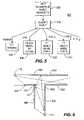
- FIG. 6depicts a “bird's eye” view of the scene 100 of FIG. 1 .
- the camerasare place such that the scene, and especially the hallway junction, is covered by multiple views of the cameras.
- Each camera 108 , 110 , 112 and 114has a particular viewing area respectively 602 , 604 , 606 and 608 .
- the three-dimensional model of the structure 100will be “draped” with the imagery collected from each of the cameras 108 , 110 , 112 and 114 such that the security guard will view a contextual model of the scene that immerses the security guard in the surveillance situation.
- the cameras 108 , 110 , 112 , 114are generally located to cover as much of the scene as possible and slightly overlap between the camera views to enable the model to align the various images with one another.
- the surveillance system of the present inventionuses the model of the scene as the coordinate system for aligning all of the imagery of the scene such that overlapping of the camera views is not necessary.
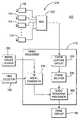
- FIG. 2depicts a block diagram of the surveillance system 102 of the present invention.
- System 102comprises a camera assembly 212 , an image processor 116 , a model update source 200 , a view selector 120 and an image display 118 .
- the camera assemblycomprises a plurality of cameras 108 , 110 , 112 and 114 coupled to a multiplexer 202 . Any number of cameras may be used and coupled to a plurality of multiplexers such that the camera assembly 212 may cover entire buildings or regions that are to be surveilled.
- the multiplexer 202combines the video streams from the, for example, four cameras by splitting the screen into four quadrants and inserting one stream in each quadrant. The stream of video frames is coupled to the image processor 116 .
- the image processor 116comprises a frame capture circuit 204 , a frame splitter 206 , an image rendering processor 208 and a 3D model generator 210 .
- a computer systemthat can be used as the image processor in accordance with the invention is a dual processor, dual PCI bus, general purpose computer comprising two Pentium 4 processors, an INVIDIA GeForce3 GPU-based video card and four frame capture circuits.
- the frame capture circuit 204captures, in a known manner, each frame of video and temporarily stores that information in a memory.
- the frame splitter 206is used to demux the video streams so that the video signal from each camera will be processed and stored independently.
- the 3D model generator 210 and the image rendering processor 208work together to generate the contextual view of the scene.
- the 3D model of scene 100is apriori generated as a wire frame or planar computer model.
- the model update source 200provides the 3D model.
- the view of the model that is to be renderedis identified by the view selector 120 .
- the view selectorcomprises a joy stick, a mouse pointer, and a zoom control such that the security guard may move about the scene as well as zoom in or out on particular objects within the scene and select various views of the scene, as needed.
- the modelis coupled to the image rendering processor where the various video images from the cameras are warped into alignment with the model and rendered upon or draped upon the model. The particular view of the model containing the view is displayed.
- the coordinate system of the modelis used for aligning the video imagery.
- the video imagesare closely aligned to the common coordinate system so that the user is easily able to determine how activity in one video relates to activity in other videos without referring to or remembering a map or 3D model of the scene. For instance, if an event deserving attention occurs in a video from one camera view and the activity then moves out of the field of view of that camera in a particular direction, the user can easily predict the new location of the activity within the view of another camera. The user is able to do this without having to remember the orientation of the camera since all video from the cameras is now aligned.
- FIG. 3depicts a flow diagram 300 of a process 300 by which the surveillance system 102 of the present invention operates.
- input imagery from the camerasis coupled to the image processor.
- the userselects a view of the scene and that view information is coupled to step 306 where the model is generated that depicts the model as viewed from the location selected in the view selection step 304 .
- the overall model of the sceneis apriori rendered using various well-known modeling techniques.
- the model generation step 306is used to produce the model from the selected viewpoint.
- an outline of the location or buildingis encoded in a 3D digital format.
- the outline modelcomprises the perimeter of the location or building and also the outline of key areas such as corridors, streets, buildings, and so on.
- the outline modelmay also contain simple attributes of the location such as room numbers.
- the source for the outline modelcan be from simple measurements recorded manually, followed by encoding into one of the 3D formats known in the art such as Alias/Wavefront OBJ, Open Inventor, VRML and the like.
- a technicianmarks the location of each camera on the outline model of the scene.
- the technicianperforms this process using information from the surrounding regions such as a room number, building shape or other distinguishing landmarks and by corresponding the camera locations manually to the outline model.
- the technicianalso defines the camera parameters such as height and orientation.
- the camera orientationcomprise the pan, tilt and roll of the cameras with respect to a global coordinate system defined by the scene. There are many methods known in the art for measuring the pan, tilt and roll of a camera, any of which are useful in building the model of the scene.
- the result of the process for defining the camera parametersis a set of parameters that define location, height, pan, tilt and roll for each camera with respect to a global outline model of the scene.
- planar surfaces of the outline model of the sceneare then modeled using well known 3D shape modeling techniques.
- one method for recovering polygons within a sceneis for the installation technician to perform simple model building using captured imagery and knowledge of the 3D shape of the scene.
- the technicianloads a single image from each camera view into a display.
- the technicianselects a set of points in the image that define the boundaries of a single planar surface in the scene, such as a wall.
- the surfaceneed not be entirely planar, objects that are attached to the surface such as heaters may be defined as belonging to a single plane.
- the technicianthen records whether the plane is approximately vertical or horizontal, or any other predetermined orientation.
- the technicianthen repeats the process for other planar surfaces in the scene and for each camera view.
- the technicianrecords the floor upon which each camera is located in a multi-floor building.
- the result of the processis a set of points in the coordinate system of the images, a set of flags defining the orientation of the surfaces in 3D and a set of numbers defining the floor upon which each camera is located.
- the model from the selected viewpoint and the input imageryare combined to render a view of the scene as directed by the security guard.
- the camera locationsare static, but from the following description it will be clear that the cameras may pan and tilt dynamically and the imagery updated dynamically to reflect the pan and tilt motion.
- the rendered view of the scenedoes not, at this point, contain moving objects.
- the rendering processis performed as described in U.S. patent application Ser. No. 09/800,550, filed Mar. 7, 2001 or a similar rendering process.
- the video from each camerais aligned to the model and warped into position.
- the warped video from each camerais applied to the model and merged to form the contextual view of the scene.
- the hallway structure of scene 100will contain walls represented with video imagery from the cameras.
- the useris presented with a “real” 3D view of the scene 100 .
- Moving objects within the sceneare processed at step 310 .
- the input imageryis processed to identify moving objects and then produce icons that are inserted into the rendered view such that the security guard may identify movement within the scene.
- the process for identifying movementis described with respect to FIG. 4 and the process for generating icons to represent the motion is described with respect to FIG. 5 below.
- the iconsare inserted into the rendered imagery.
- the process 300queries whether the rendered imagery should be stored. If the query at step 316 is answered affirmatively, the imagery is stored either on video tape or in digital memory at step 318 . Such storage allows the model and its constituent video to be “rewound” and “replayed” by the security guard, if desired.
- a rendered image and iconsare displayed for the security guard.
- the process 300queries whether a new view is selected by the security guard. If a new view is not selected, the process returns to step 302 and processes more of the video streams from the cameras. If a new view has been selected, then the process returns to both steps 302 and 304 to generate a new model of the new view as well as apply the new imagery to the new view of the model.
- the cameras used to produce the videohave pan/tilt/zoom (PTZ) features, this camera motion must be accommodated when rendering views of a scene.
- PTZpan/tilt/zoom
- the systemcan read this information directly from the camera. Then, the system accesses a look-up table to find the pose of the camera within the geometry of the scene given the PTZ values. The pose is used to render a display.
- a calibration processTo create the pose look-up table, a calibration process must be performed.
- the camerais pointed at a particular location in the scene and a user identifies (typically by pointing and clicking a mouse pointer) points in the image and corresponding points in the 3D model.
- the systemthen computes the rotation portion of the pose for that particular set of PTZ values. This procedure is repeated for several images having the camera pointed in various directions.
- the captured PTZ values and the computed pose for each directionare stored in the pose look-up table.
- An interpolation algorithmthen computes PTZ and pose values between the measured values to fully populate the pose look-up table.
- a second techniquealigns the video to a spherical image mosaic that itself has been aligned (possibly manually) to the 3D model.
- Thisis a robust technique because image-to-image alignment is performed rather than image-to-model alignment.
- Spherical image mosaicsare a priori produced in a conventional manner for each camera having PTZ features. These mosaics are aligned to the 3D model and stored. Subsequent images from the cameras are aligned to the mosaics to provide accurate alignment of current images to the 3D model. To ensure alignment errors will not occur during changes in scene illumination, either multiple mosaics for each camera can be produced at various light levels or techniques disclosed in U.S. patent application Ser. No. 09/075,462, filed May 8, 1998, incorporated herein by reference, can be used to align images over broad variations in illumination.
- FIG. 4depicts a process 401 (performed at step 310 of FIG. 3 ) for identifying moving objects within the scene.
- the image sequenceis input to the process.
- the image sequenceis processed by both a two-dimensional (2D) module 418 and a three-dimensional (3D) module 420 .
- the 2D module 418separates foreground objects from the static background scene.
- the 3D module 420performs depth and shape recovery to enable the process 401 to identify the form of object that is moving in the scene.
- the static background information (a reference image) within the sceneis extracted from the image sequence using a well known filtering technique that remove foreground motion from a video sequence.
- One such methodis disclosed in European Patent Publication Number EP 1045591.
- the reference imageis then subtracted from the original image sequence at step 404 to produce a two dimensional (2D) object silhouette for each moving object in the scene. All moving objects will be appear as a silhouette in step 406 .
- three dimensional informationis necessary to identify and isolate moving objects versus objects that apparently move because of camera movement, shadows, and the like.
- Such three dimensional processingis performed in the 3D module comprising steps 408 , 410 , 412 and 414 .
- depth informationis computed from the image sequence.
- background depth informationis computed or determined and, at step 412 , the background depth information is subtracted from the depth information gleaned from the image sequence to produce foreground object depth information only.
- the foreground depth informationis combined with the object silhouette information at step 414 to produce three dimensional object silhouettes at step 416 .
- the object silhouettes produced at step 416accurately depict the foreground objects that are moving within a scene.
- each object silhouetteis rendered into a three dimensional model then when the model is inserted as an icon into the rendered imagery of the scene that foreground object can be visualized from different viewpoints and appear geometrically correct within the scene.
- FIG. 5depicts a flow diagram of a process 501 (performed at step 312 of FIG. 3 ) for generating icons that are three dimensional models of moving objects within a scene.
- the 2D and/or 3D object silhouettes from process 401 of FIG. 4are input into the process 501 .
- the object silhouettesgenerally comprise both depth and/or shape information from the depth estimation module as well as textural information such as color and brightness. For example, significant textural discontinuities that are also close to the significant depth discontinuities can be classified to be part of the outline or silhouette of the object.
- the object silhouetteis classified. The purpose of this classification step is to identify the model type that should be fit to the foreground object. Classification can be performed by analyzing attributes of the object.
- Examples of attributesinclude size and shape of the silhouette.
- An example of a method that can recover the attributes of an objectis a moment analysis.
- the first and second order moments computed on the foreground objectcan be used to determine whether or not an object is slender.
- a slender objectmay be classified as a human, and non-slender object may be classified as another type of object such as a vehicle.
- different models for the objectcan be invoked. For example, at step 504 , a human may be modeled by a set of spheres and, at step 506 , a vehicle can be modeled as a box. Other object would be modeled as various types in steps 508 and 510 .
- These icons (object models)are inserted into the rendered imagery as described above.
- FIG. 7depicts an illustrative display screen that may be viewed by a security guard.
- the view screen 700depicts a “birds eye” view of the monitored scene in region 710 and depicts, in region 712 four of the live camera views from each of the four cameras 108 , 110 , 112 and 114 .
- region 710is a rendering of the hallway structure 100 of FIG. 1 containing the moving objects that were identified by the moving object detection process 401 and rendered as icons by the moving object icon generator 501 .
- the iconsare 702 , 704 and 706 are generally shown as different color “dots” depending on the camera that is capturing the movement of the object.
- icon 702may be shown in red and the icon 716 for the camera (camera 110 ) that is capturing that movement would also be shown in red.
- camera icon 714may be shown in blue and object 704 would also be in blue.
- the trailing shadow 708may be used to show prior positions of the moving object as it moves through the scene.
- Object icon 706contains shadow trail 708 to show movement of the object along hallway 104 .
- the security guardmay receive additional information from erratic or abnormal movement of an object through a scene.
- the security guardmay place the mouse pointer upon the object and click or double click to select that object.
- the surveillance systemAfter selection, the surveillance system generates a view of that object from either a particular camera location or a synthetic camera location that is rendered from the multiple cameras viewing a scene.
- FIG. 8depicts a synthetic view from a location in hallway 106 of object 702 .
- This synthetic viewcan be manipulated using a zoom control to zoom in/out on the object, or use a joy stick to move within the scene to get a better view of the object and its destination.
- the security guardcan always select a live view of the scene as taken from a camera that is currently imaging the object.
- the rendered view 702shows a sphere based model of a person walking along the hallway 106 . As the camera angle is panned or tilted for the synthetic view generated from a different location, the three dimensional spherical model will render a person walking down the hallway.
- the walls and floors of the rendered imageare textured from the video that is produced by the cameras such that the synthetic view is as accurate as an actual camera view of the scene.
- the identification of the moving object and then rendering a specific image of a portion of the entire scene with that object within the sceneis known as a “flashlight mode” of operation.
- the process used for rendering flashlight mode imageryis described in U.S. patent application Ser. No. 09/800,550, filed Mar. 7, 2001.
- the present systeminvolves substantial flexibility in the view point and video rendering of a scene.
- the view selectormay include specific go to points for the operator to check on a regular basis.
- the viewmay contain camera icons so that the security guard may know exactly what views are available from the live feeds.
- a top view of the motion as depicted in FIG. 7is available.
- the security guardmay fly through the image imagery to take a virtual walk through of the scene from a remote location and, at any time, full resolution video is available from the feeds of each of the cameras such that the security guard may elect a full resolution view of the imagery in the scene.
- imagerymay be annotated when the mouse pointer is pointed to certain locations within a scene to show the location information regarding that scene or object identification. For example, if a person has entered through a secure check point that person's name and ID number may appear on the screen when that person's icon is identified within the scene. As such, the person could be tracked as they moved through a secure area. Alternatively, a person could be observed in a particular location, the user could request identification, and the full resolution video could be sampled by a face recognition system to identify the person. An annotation of the person's identification could then appear on the three dimensional contextual view of the scene. The user could then track the person as they moved through the facility. If the person could not be identified, security personnel could be dispatched to intercept the unidentified person.
- FIG. 9Another embodiment of the present invention is depicted in FIG. 9 where an implicit 3D model is used to provide an intuitive map that interconnects image sequences.
- the system 900comprises a plurality of video cameras, or other sources of imagery, 902 , 904 , 906 and 908 that produce a plurality of video sequences.
- the video sequencesare coupled to an image processor 912 that contains an implicit 3D model 918 .
- the model 918can be created using the model update source 914 .
- a view selector 910is coupled to the image processor 912 .
- the view selector 910is manipulated by a user such that views of the imagery taken by the cameras 902 , 904 , 906 and 908 are displayed on the image display 916 .
- the model update source 914is used to create an implicit 3D model in an apriori manner by a user.
- the implicit 3D modelcreates a map that interconnects the views of the various cameras such that, as an object moves through a scene that is imaged by the cameras, a simple selection of a view using a mouse pointer on the screen will automatically display the best view of the selected image area.
- the map(the implicit model) identifies interconnections between video sequences.
- the mapis a look-up table that comprises, for each video sequence, a transition region and a video sequence associated with the transition region.
- the transition regionmay be a single pixel or a region of pixels.
- Each video sequenceis given a unique identification number.
- the unique identification numbersmay be associated with one or more transition regions.
- each sequencehas a transition region at 0, 90, 180 and 270 degrees with the coordinate system of an image. These regions are located at the top, bottom, right and left edges of an image. Other locations may be used. Using the four locations, a user can select a transition region into which an object moves such that a more appropriate view of the object is displayed.
- the implicit maponly needs to be created once.
- the userneeds to have knowledge of only the overlaps of the video produced by the cameras then the map can be created having the user identify which cameras overlap with each other camera or closely overlap each other. Note that there does not need to be an explicit overlap between the images.
- the userneed only identify which camera view is desired to be shown next if a target happens to be moving in a particular direction. For each camera that overlaps or nearly overlaps, a user draws a rectangle or other shaped region of interest in the image and keys in which camera should be displayed if an object is moving in a particular direction within that region.
- FIG. 11Dshows an example scene having three cameras 1104 , 1106 and 1108 .
- the coordinate system for each imageis shown at scale 1150 .
- Each cameracovers a particular region 1114 , 1112 and 1110 that is imaged by each of the cameras.
- Table 1identifies the implicit three dimensional model (map) for the camera arrangement in FIG. 11D .
- camera 1has only one available transition to camera 2 when an object moves in the region at 270 degrees.
- Camera 2transitions to camera 1 at 90 degrees, camera 3 at 0 degrees and camera 3 also 180 degrees and, lastly, camera 3 transitions to camera 2 at 0 degrees and again at camera 2 at 180 degrees.
- FIGS. 11A , 11 B and 11 Cdepict the three views from cameras 1104 , 1106 and 1108 as an object follows path 1102 shown in FIG. 11D .
- the objectbegins at position 1116 and transitions from right to left in FIG. 11A in the view of camera 1104 .
- the cursor 1120may be placed on the object or in the region 1118 to select a new view.
- the transitions as defined in table 1will identify camera 2 at the 270 degree region as the next camera to use to best view the object.
- FIG. 11Bshows the object moving in the view of camera 2 from left to the 0 degree region 1128 .
- cursor 1120may be placed upon the region and selected, the table is then used again to identify the next view of the scene to best image the moving object.
- the third camera 1108is now selected as the object begins at position 1130 and moves to position 1132 .
- the objectthen moves from position 1130 to position 1132 .
- the objectthen transitions out of the scene.
- an implicit 3D modelcan easily be created to enable a user to quickly follow a moving object through the scene through any number of cameras that have been used to establish the implicit 3 dimensional model.
- FIG. 10is a method of the alternative embodiment of the invention.
- the method 1000begins at step 1002 with an input of a plurality of video sequences from the cameras.
- the video sequencesare registered to an implicit relationship model as defined by the user selecting regions to identify cameras to which to transition.
- a view of the sceneis selected using an input device such as a mouse, track pad, track ball and the like.
- a sequenceis selected for display as identified in step 1010 , based on the placement of the cursor as discussed above.
- the selected video sequenceis then displayed at step 1008 .
- This systemprovides and intuitive and simple manner for a user to follow an object through a scene. An operator can easily navigate around the scene by placing the cursor in a transition region within a particular video frame and selecting that region. If the operator wishes to see around a building corner, the operator can select the region of the corner and the best view around the corner would be displayed.
- the view selectorwas described as being manipulated by a user to select a view of the scene.
- the view selectormay be automated. For example, when motion is detected in the scene (or a particular type of motion is detected), the view selector may automatically select a view that best displays the region of the scene containing the motion.
- the view selectormay automatically select a view that best displays the region of the scene containing the motion.
Landscapes
- Engineering & Computer Science (AREA)
- Physics & Mathematics (AREA)
- General Physics & Mathematics (AREA)
- Theoretical Computer Science (AREA)
- Computer Vision & Pattern Recognition (AREA)
- Multimedia (AREA)
- Computer Graphics (AREA)
- Signal Processing (AREA)
- Geometry (AREA)
- Computing Systems (AREA)
- Human Computer Interaction (AREA)
- Computer Hardware Design (AREA)
- General Engineering & Computer Science (AREA)
- Software Systems (AREA)
- Processing Or Creating Images (AREA)
- Closed-Circuit Television Systems (AREA)
- Burglar Alarm Systems (AREA)
Abstract
Description
| TABLE 1 | ||
| 2, 270° | 1, 90° | 2, 0° |
| 3, 0° | 2, 180° | |
| 3, 180° | ||
Claims (40)
Priority Applications (8)
| Application Number | Priority Date | Filing Date | Title |
|---|---|---|---|
| US10/202,546US7522186B2 (en) | 2000-03-07 | 2002-07-24 | Method and apparatus for providing immersive surveillance |
| EP02806001AEP1449180A4 (en) | 2001-11-02 | 2002-10-31 | Method and apparatus for providing immersive surveillance |
| CA002466085ACA2466085A1 (en) | 2001-11-02 | 2002-10-31 | Method and apparatus for providing immersive surveillance |
| IL16140002AIL161400A0 (en) | 2001-11-02 | 2002-10-31 | Method and apparatus for providing immersive surveillance |
| JP2003566812AJP2005517253A (en) | 2001-11-02 | 2002-10-31 | Method and apparatus for providing an infiltration lookout |
| KR1020047006666AKR100940142B1 (en) | 2001-11-02 | 2002-10-31 | Method and apparatus for providing immersive surveillance |
| PCT/US2002/034913WO2003067537A2 (en) | 2001-11-02 | 2002-10-31 | Method and apparatus for providing immersive surveillance |
| US12/404,261US20090237508A1 (en) | 2000-03-07 | 2009-03-13 | Method and apparatus for providing immersive surveillance |
Applications Claiming Priority (4)
| Application Number | Priority Date | Filing Date | Title |
|---|---|---|---|
| US18755700P | 2000-03-07 | 2000-03-07 | |
| US09/800,550US6985620B2 (en) | 2000-03-07 | 2001-03-07 | Method of pose estimation and model refinement for video representation of a three dimensional scene |
| US33972601P | 2001-11-02 | 2001-11-02 | |
| US10/202,546US7522186B2 (en) | 2000-03-07 | 2002-07-24 | Method and apparatus for providing immersive surveillance |
Related Parent Applications (1)
| Application Number | Title | Priority Date | Filing Date |
|---|---|---|---|
| US09/800,550Continuation-In-PartUS6985620B2 (en) | 2000-03-07 | 2001-03-07 | Method of pose estimation and model refinement for video representation of a three dimensional scene |
Related Child Applications (1)
| Application Number | Title | Priority Date | Filing Date |
|---|---|---|---|
| US12/404,261ContinuationUS20090237508A1 (en) | 2000-03-07 | 2009-03-13 | Method and apparatus for providing immersive surveillance |
Publications (2)
| Publication Number | Publication Date |
|---|---|
| US20030085992A1 US20030085992A1 (en) | 2003-05-08 |
| US7522186B2true US7522186B2 (en) | 2009-04-21 |
Family
ID=26897783
Family Applications (2)
| Application Number | Title | Priority Date | Filing Date |
|---|---|---|---|
| US10/202,546Expired - Fee RelatedUS7522186B2 (en) | 2000-03-07 | 2002-07-24 | Method and apparatus for providing immersive surveillance |
| US12/404,261AbandonedUS20090237508A1 (en) | 2000-03-07 | 2009-03-13 | Method and apparatus for providing immersive surveillance |
Family Applications After (1)
| Application Number | Title | Priority Date | Filing Date |
|---|---|---|---|
| US12/404,261AbandonedUS20090237508A1 (en) | 2000-03-07 | 2009-03-13 | Method and apparatus for providing immersive surveillance |
Country Status (7)
| Country | Link |
|---|---|
| US (2) | US7522186B2 (en) |
| EP (1) | EP1449180A4 (en) |
| JP (1) | JP2005517253A (en) |
| KR (1) | KR100940142B1 (en) |
| CA (1) | CA2466085A1 (en) |
| IL (1) | IL161400A0 (en) |
| WO (1) | WO2003067537A2 (en) |
Cited By (47)
| Publication number | Priority date | Publication date | Assignee | Title |
|---|---|---|---|---|
| US20060093190A1 (en)* | 2004-09-17 | 2006-05-04 | Proximex Corporation | Adaptive multi-modal integrated biometric identification detection and surveillance systems |
| US20060285723A1 (en)* | 2005-06-16 | 2006-12-21 | Vassilios Morellas | Object tracking system |
| US20070058885A1 (en)* | 2004-04-02 | 2007-03-15 | The Boeing Company | Method and system for image registration quality confirmation and improvement |
| US20070086675A1 (en)* | 2005-10-13 | 2007-04-19 | Fujifilm Software(California), Inc. | Segmenting images and simulating motion blur using an image sequence |
| US20070291991A1 (en)* | 2006-06-16 | 2007-12-20 | National Institute Of Advanced Industrial Science And Technology | Unusual action detector and abnormal action detecting method |
| US20080018740A1 (en)* | 2006-07-18 | 2008-01-24 | Fuji Xerox Co., Ltd. | Remote instruction system |
| US20080050042A1 (en)* | 2006-05-31 | 2008-02-28 | Zhang Guangjun | Hardware-in-the-loop simulation system and method for computer vision |
| US20080074494A1 (en)* | 2006-09-26 | 2008-03-27 | Harris Corporation | Video Surveillance System Providing Tracking of a Moving Object in a Geospatial Model and Related Methods |
| US20080123975A1 (en)* | 2004-09-08 | 2008-05-29 | Nobuyuki Otsu | Abnormal Action Detector and Abnormal Action Detecting Method |
| US20080298693A1 (en)* | 2007-05-31 | 2008-12-04 | Arun Hampapur | Method, system, and program product for presenting electronic surveillance data |
| US20090237508A1 (en)* | 2000-03-07 | 2009-09-24 | L-3 Communications Corporation | Method and apparatus for providing immersive surveillance |
| US20100021067A1 (en)* | 2006-06-16 | 2010-01-28 | Nobuyuki Otsu | Abnormal area detection apparatus and abnormal area detection method |
| US20100111444A1 (en)* | 2007-04-24 | 2010-05-06 | Coffman Thayne R | Method and system for fast dense stereoscopic ranging |
| US20100166259A1 (en)* | 2006-08-17 | 2010-07-01 | Nobuyuki Otsu | Object enumerating apparatus and object enumerating method |
| US20100194861A1 (en)* | 2009-01-30 | 2010-08-05 | Reuben Hoppenstein | Advance in Transmission and Display of Multi-Dimensional Images for Digital Monitors and Television Receivers using a virtual lens |
| US7777783B1 (en)* | 2007-03-23 | 2010-08-17 | Proximex Corporation | Multi-video navigation |
| US20100278508A1 (en)* | 2009-05-04 | 2010-11-04 | Mamigo Inc | Method and system for scalable multi-user interactive visualization |
| US20110007948A1 (en)* | 2004-04-02 | 2011-01-13 | The Boeing Company | System and method for automatic stereo measurement of a point of interest in a scene |
| US20110044502A1 (en)* | 2009-04-28 | 2011-02-24 | Hisense State Key Laboratory Of Digital Multi-Media Technology Co., Ltd. | Motion detection method, apparatus and system |
| US20110102586A1 (en)* | 2009-11-05 | 2011-05-05 | Hon Hai Precision Industry Co., Ltd. | Ptz camera and controlling method of the ptz camera |
| US20110255739A1 (en)* | 2010-04-16 | 2011-10-20 | Hon Hai Precision Industry Co., Ltd. | Image capturing device and method with object tracking |
| US20110285810A1 (en)* | 2010-05-21 | 2011-11-24 | Qualcomm Incorporated | Visual Tracking Using Panoramas on Mobile Devices |
| US20120105602A1 (en)* | 2010-11-03 | 2012-05-03 | 3Dmedia Corporation | Methods, systems, and computer program products for creating three-dimensional video sequences |
| US20120105581A1 (en)* | 2010-10-29 | 2012-05-03 | Sony Corporation | 2d to 3d image and video conversion using gps and dsm |
| US8193909B1 (en)* | 2010-11-15 | 2012-06-05 | Intergraph Technologies Company | System and method for camera control in a surveillance system |
| US20120155778A1 (en)* | 2010-12-16 | 2012-06-21 | Microsoft Corporation | Spatial Image Index and Associated Updating Functionality |
| US20120188333A1 (en)* | 2009-05-27 | 2012-07-26 | The Ohio State University | Spherical view point controller and method for navigating a network of sensors |
| US20120300020A1 (en)* | 2011-05-27 | 2012-11-29 | Qualcomm Incorporated | Real-time self-localization from panoramic images |
| US20130010111A1 (en)* | 2010-03-26 | 2013-01-10 | Christian Laforte | Effortless Navigation Across Cameras and Cooperative Control of Cameras |
| WO2012056443A3 (en)* | 2010-10-24 | 2013-05-10 | Rafael Advanced Defense Systems Ltd. | Tracking and identification of a moving object from a moving sensor using a 3d model |
| US8723920B1 (en) | 2011-07-05 | 2014-05-13 | 3-D Virtual Lens Technologies, Llc | Encoding process for multidimensional display |
| US8817067B1 (en)* | 2011-07-29 | 2014-08-26 | Google Inc. | Interface for applying a photogrammetry algorithm to panoramic photographic images |
| US8929645B2 (en) | 2007-04-24 | 2015-01-06 | 21 Ct, Inc. | Method and system for fast dense stereoscopic ranging |
| US8933986B2 (en) | 2010-05-28 | 2015-01-13 | Qualcomm Incorporated | North centered orientation tracking in uninformed environments |
| US9195883B2 (en) | 2012-04-09 | 2015-11-24 | Avigilon Fortress Corporation | Object tracking and best shot detection system |
| US9305401B1 (en)* | 2007-06-06 | 2016-04-05 | Cognitech, Inc. | Real-time 3-D video-security |
| US9544563B1 (en) | 2007-03-23 | 2017-01-10 | Proximex Corporation | Multi-video navigation system |
| US9613448B1 (en)* | 2014-03-14 | 2017-04-04 | Google Inc. | Augmented display of information in a device view of a display screen |
| US20180330163A1 (en)* | 2017-05-11 | 2018-11-15 | Canon Kabushiki Kaisha | Image processing apparatus and image processing method |
| US20190208167A1 (en)* | 2014-10-30 | 2019-07-04 | Nec Corporation | Camera listing based on comparison of imaging range coverage information to event-related data generated based on captured image |
| US10412594B2 (en) | 2014-07-31 | 2019-09-10 | At&T Intellectual Property I, L.P. | Network planning tool support for 3D data |
| US20190304195A1 (en)* | 2018-04-03 | 2019-10-03 | Saeed Eslami | Augmented reality application system and method |
| US10574975B1 (en) | 2018-08-08 | 2020-02-25 | At&T Intellectual Property I, L.P. | Method and apparatus for navigating through panoramic content |
| US11113887B2 (en)* | 2018-01-08 | 2021-09-07 | Verizon Patent And Licensing Inc | Generating three-dimensional content from two-dimensional images |
| US11310423B2 (en) | 2019-12-16 | 2022-04-19 | Industrial Technology Research Institute | Image capturing method and image capturing apparatus |
| US20220375159A1 (en)* | 2019-10-29 | 2022-11-24 | Koninklijke Philips N.V. | An image processing method for setting transparency values and color values of pixels in a virtual image |
| US20230419662A1 (en)* | 2021-02-25 | 2023-12-28 | MFTB Holdco, Inc. | Automated Usability Assessment Of Buildings Using Visual Data Of Captured In-Room Images |
Families Citing this family (146)
| Publication number | Priority date | Publication date | Assignee | Title |
|---|---|---|---|---|
| US7868912B2 (en)* | 2000-10-24 | 2011-01-11 | Objectvideo, Inc. | Video surveillance system employing video primitives |
| US8564661B2 (en) | 2000-10-24 | 2013-10-22 | Objectvideo, Inc. | Video analytic rule detection system and method |
| US8711217B2 (en)* | 2000-10-24 | 2014-04-29 | Objectvideo, Inc. | Video surveillance system employing video primitives |
| US9892606B2 (en)* | 2001-11-15 | 2018-02-13 | Avigilon Fortress Corporation | Video surveillance system employing video primitives |
| US20050146605A1 (en)* | 2000-10-24 | 2005-07-07 | Lipton Alan J. | Video surveillance system employing video primitives |
| JP2004072349A (en)* | 2002-08-05 | 2004-03-04 | Canon Inc | Imaging device and control method thereof |
| AU2003277240A1 (en)* | 2002-10-15 | 2004-06-07 | University Of Southern California | Augmented virtual environments |
| US20040075741A1 (en)* | 2002-10-17 | 2004-04-22 | Berkey Thomas F. | Multiple camera image multiplexer |
| JP3700707B2 (en)* | 2003-03-13 | 2005-09-28 | コニカミノルタホールディングス株式会社 | Measuring system |
| US20040223054A1 (en)* | 2003-05-06 | 2004-11-11 | Rotholtz Ben Aaron | Multi-purpose video surveillance |
| US7577636B2 (en) | 2003-05-28 | 2009-08-18 | Fernandez Dennis S | Network-extensible reconfigurable media appliance |
| CA2529903A1 (en)* | 2003-06-19 | 2004-12-29 | Sarnoff Corporation | Method and apparatus for providing a scalable multi-camera distributed video processing and visualization surveillance system |
| US7259778B2 (en)* | 2003-07-01 | 2007-08-21 | L-3 Communications Corporation | Method and apparatus for placing sensors using 3D models |
| EP1673748A2 (en)* | 2003-10-09 | 2006-06-28 | De Beers Consolidated Mines Limited | Enhanced video based surveillance system |
| EP1673938A2 (en)* | 2003-10-09 | 2006-06-28 | De Beers Consolidated Mines Limited | Augmented video surveillance system |
| GB2409123B (en) | 2003-12-03 | 2009-07-01 | Safehouse Internat Inc | Analysing image data |
| US7428314B2 (en)* | 2003-12-03 | 2008-09-23 | Safehouse International Inc. | Monitoring an environment |
| DE10358017A1 (en)* | 2003-12-11 | 2005-07-21 | Siemens Ag | 3D camera control |
| JP4424031B2 (en)* | 2004-03-30 | 2010-03-03 | 株式会社日立製作所 | Image generating apparatus, system, or image composition method. |
| US20070226616A1 (en)* | 2004-06-01 | 2007-09-27 | L-3 Communications Corporation | Method and System For Wide Area Security Monitoring, Sensor Management and Situational Awareness |
| US7813525B2 (en)* | 2004-06-01 | 2010-10-12 | Sarnoff Corporation | Method and apparatus for detecting suspicious activities |
| US8063936B2 (en)* | 2004-06-01 | 2011-11-22 | L-3 Communications Corporation | Modular immersive surveillance processing system and method |
| JP2008512733A (en)* | 2004-06-01 | 2008-04-24 | エル‐3 コミュニケーションズ コーポレイション | Wide range of security monitoring, sensor management and situation recognition methods and systems |
| US7639840B2 (en)* | 2004-07-28 | 2009-12-29 | Sarnoff Corporation | Method and apparatus for improved video surveillance through classification of detected objects |
| US8289390B2 (en)* | 2004-07-28 | 2012-10-16 | Sri International | Method and apparatus for total situational awareness and monitoring |
| SE528330C2 (en)* | 2004-11-11 | 2006-10-24 | Totalfoersvarets Forskningsins | Method for monitoring a geographical area |
| EP1834312A2 (en)* | 2005-01-03 | 2007-09-19 | Vumii, Inc. | Systems and methods for night time surveillance |
| US10019877B2 (en)* | 2005-04-03 | 2018-07-10 | Qognify Ltd. | Apparatus and methods for the semi-automatic tracking and examining of an object or an event in a monitored site |
| US7583815B2 (en)* | 2005-04-05 | 2009-09-01 | Objectvideo Inc. | Wide-area site-based video surveillance system |
| US20080291278A1 (en)* | 2005-04-05 | 2008-11-27 | Objectvideo, Inc. | Wide-area site-based video surveillance system |
| US20060233461A1 (en)* | 2005-04-19 | 2006-10-19 | Honeywell International Inc. | Systems and methods for transforming 2d image domain data into a 3d dense range map |
| US7945938B2 (en)* | 2005-05-11 | 2011-05-17 | Canon Kabushiki Kaisha | Network camera system and control method therefore |
| WO2007031947A2 (en)* | 2005-09-12 | 2007-03-22 | Carlos Tapang | Frame and pixel based matching of model-generated graphics images to camera frames |
| US8848035B2 (en)* | 2005-10-04 | 2014-09-30 | Motion Analysis Corporation | Device for generating three dimensional surface models of moving objects |
| EP1941719A4 (en)* | 2005-10-04 | 2010-12-22 | Eugene J Alexander | System and method for calibrating a set of imaging devices and calculating 3d coordinates of detected features in a laboratory coordinate system |
| US7697850B2 (en)* | 2005-10-31 | 2010-04-13 | Infoprint Solutions Company, Llc | Image-based printer system monitoring |
| WO2007058900A2 (en)* | 2005-11-10 | 2007-05-24 | Alexander Eugene J | Calibrating an imaging device for generating three dimensional suface models of moving objects |
| US8949235B2 (en) | 2005-11-15 | 2015-02-03 | Yissum Research Development Company Of The Hebrew University Of Jerusalem Ltd. | Methods and systems for producing a video synopsis using clustering |
| EP1955205B1 (en)* | 2005-11-15 | 2012-08-29 | Yissum Research Development Company Of The Hebrew University Of Jerusalem | Method and system for producing a video synopsis |
| US7652617B2 (en)* | 2006-06-01 | 2010-01-26 | University Of Florida Research Foundation, Inc. | Radar microsensor for detection, tracking, and classification |
| US20080036864A1 (en)* | 2006-08-09 | 2008-02-14 | Mccubbrey David | System and method for capturing and transmitting image data streams |
| US8121356B2 (en)* | 2006-09-15 | 2012-02-21 | Identix Incorporated | Long distance multimodal biometric system and method |
| US8482609B1 (en)* | 2006-11-22 | 2013-07-09 | Sightlogix, Inc. | Methods and apparatus related to surveillance system marketing, planning and/or integration |
| JP5538667B2 (en)* | 2007-04-26 | 2014-07-02 | キヤノン株式会社 | Position / orientation measuring apparatus and control method thereof |
| ITMI20071016A1 (en)* | 2007-05-19 | 2008-11-20 | Videotec Spa | METHOD AND SYSTEM FOR SURPRISING AN ENVIRONMENT |
| US8350908B2 (en)* | 2007-05-22 | 2013-01-08 | Vidsys, Inc. | Tracking people and objects using multiple live and recorded surveillance camera video feeds |
| US8009178B2 (en)* | 2007-06-29 | 2011-08-30 | Microsoft Corporation | Augmenting images for panoramic display |
| US8542872B2 (en)* | 2007-07-03 | 2013-09-24 | Pivotal Vision, Llc | Motion-validating remote monitoring system |
| WO2009057436A1 (en)* | 2007-11-01 | 2009-05-07 | Konica Minolta Holdings, Inc. | Imaging device |
| CN101939765B (en)* | 2007-12-10 | 2014-01-29 | Abb研究有限公司 | Computer-implemented method and system for remote inspection of industrial processes |
| GB2457707A (en)* | 2008-02-22 | 2009-08-26 | Crockford Christopher Neil Joh | Integration of video information |
| FR2932351B1 (en)* | 2008-06-06 | 2012-12-14 | Thales Sa | METHOD OF OBSERVING SCENES COVERED AT LEAST PARTIALLY BY A SET OF CAMERAS AND VISUALIZABLE ON A REDUCED NUMBER OF SCREENS |
| US8311275B1 (en) | 2008-06-10 | 2012-11-13 | Mindmancer AB | Selective viewing of a scene |
| TW200952486A (en)* | 2008-06-13 | 2009-12-16 | Ind Tech Res Inst | Video surveillance system, module and method for annotation and de-annotation thereof |
| US9071626B2 (en) | 2008-10-03 | 2015-06-30 | Vidsys, Inc. | Method and apparatus for surveillance system peering |
| JP2010206475A (en)* | 2009-03-03 | 2010-09-16 | Fujitsu Ltd | Monitoring support device, method thereof, and program |
| US8862987B2 (en)* | 2009-03-31 | 2014-10-14 | Intel Corporation | Capture and display of digital images based on related metadata |
| WO2010116364A1 (en)* | 2009-04-05 | 2010-10-14 | Tadsec Advanced Homeland Security Technologies Ltd | A security management system and method |
| US8890937B2 (en) | 2009-06-01 | 2014-11-18 | The Curators Of The University Of Missouri | Anonymized video analysis methods and systems |
| FR2946440B1 (en)* | 2009-06-05 | 2012-01-13 | Thales Sa | DEVICE FOR SIMULATION OF AN ENVIRONMENT OF A SYSTEM OF SUPERVISION OF AN INFRASTRUCTURE |
| WO2011022577A1 (en)* | 2009-08-20 | 2011-02-24 | Purdue Research Foundation | Predictive duty cycle adaptation scheme for event-driven wireless sensor networks |
| CN101635840B (en)* | 2009-08-26 | 2011-04-20 | 中兴通讯股份有限公司 | Video monitoring scene switching method and video monitoring system |
| US20110110557A1 (en)* | 2009-11-06 | 2011-05-12 | Nicholas Clark | Geo-locating an Object from Images or Videos |
| CN102687513B (en) | 2009-11-10 | 2015-09-09 | Lg电子株式会社 | The method of record and playback of video data and the display unit of use the method |
| EP2499827A4 (en)* | 2009-11-13 | 2018-01-03 | Pixel Velocity, Inc. | Method for tracking an object through an environment across multiple cameras |
| KR20110079164A (en)* | 2009-12-31 | 2011-07-07 | 삼성테크윈 주식회사 | Camera handoff method and monitoring device using the same |
| DE102010003336A1 (en)* | 2010-03-26 | 2011-09-29 | Robert Bosch Gmbh | Method for the visualization of activity focuses in surveillance scenes |
| US9569442B2 (en)* | 2010-04-27 | 2017-02-14 | The Radiant Group, Inc. | Geo-location video archive system and method |
| US8531504B2 (en) | 2010-06-11 | 2013-09-10 | Intel Corporation | System and method for 3D video stabilization by fusing orientation sensor readings and image alignment estimates |
| TW201215078A (en)* | 2010-09-21 | 2012-04-01 | Hon Hai Prec Ind Co Ltd | Handheld device and method for changing an image source using the handheld device |
| JP5883881B2 (en)* | 2010-11-17 | 2016-03-15 | オムロン サイエンティフィック テクノロジーズ, インコーポレイテッドOmron Scientific Technologies, Inc. | Method and apparatus for monitoring zones |
| KR20120065817A (en)* | 2010-12-13 | 2012-06-21 | 한국전자통신연구원 | Method and system for providing intelligent access monitoring, intelligent access monitoring apparatus, recording medium for intelligent access monitoring |
| MY171846A (en)* | 2010-12-27 | 2019-11-04 | Mimos Berhad | System and method for navigation and visualization |
| US9746988B2 (en)* | 2011-05-23 | 2017-08-29 | The Boeing Company | Multi-sensor surveillance system with a common operating picture |
| KR101302803B1 (en)* | 2011-05-26 | 2013-09-02 | 주식회사 엘지씨엔에스 | Intelligent image surveillance system using network camera and method therefor |
| FR2976107B1 (en)* | 2011-05-30 | 2014-01-03 | Commissariat Energie Atomique | METHOD FOR LOCATING A CAMERA AND 3D RECONSTRUCTION IN A PARTIALLY KNOWN ENVIRONMENT |
| US9129400B1 (en)* | 2011-09-23 | 2015-09-08 | Amazon Technologies, Inc. | Movement prediction for image capture |
| US20140340404A1 (en)* | 2011-12-16 | 2014-11-20 | Thomson Licensing | Method and apparatus for generating 3d free viewpoint video |
| US20130208123A1 (en)* | 2012-02-13 | 2013-08-15 | Honeywell International Inc. | Method and System for Collecting Evidence in a Security System |
| US9597016B2 (en) | 2012-04-27 | 2017-03-21 | The Curators Of The University Of Missouri | Activity analysis, fall detection and risk assessment systems and methods |
| US9408561B2 (en) | 2012-04-27 | 2016-08-09 | The Curators Of The University Of Missouri | Activity analysis, fall detection and risk assessment systems and methods |
| US9846960B2 (en) | 2012-05-31 | 2017-12-19 | Microsoft Technology Licensing, Llc | Automated camera array calibration |
| US9767598B2 (en) | 2012-05-31 | 2017-09-19 | Microsoft Technology Licensing, Llc | Smoothing and robust normal estimation for 3D point clouds |
| US20130321564A1 (en) | 2012-05-31 | 2013-12-05 | Microsoft Corporation | Perspective-correct communication window with motion parallax |
| WO2013183738A1 (en)* | 2012-06-08 | 2013-12-12 | ソニー株式会社 | Information processing device, information processing method, program, and surveillance camera system |
| US9087386B2 (en) | 2012-11-30 | 2015-07-21 | Vidsys, Inc. | Tracking people and objects using multiple live and recorded surveillance camera video feeds |
| US10084994B2 (en)* | 2012-12-12 | 2018-09-25 | Verint Systems Ltd. | Live streaming video over 3D |
| US9648075B1 (en)* | 2012-12-18 | 2017-05-09 | Google Inc. | Systems and methods for providing an event map |
| JP6171374B2 (en) | 2013-02-06 | 2017-08-02 | ソニー株式会社 | Information processing apparatus, information processing method, program, and information processing system |
| KR101383997B1 (en)* | 2013-03-08 | 2014-04-10 | 홍익대학교 산학협력단 | Real-time video merging method and system, visual surveillance system and virtual visual tour system using the real-time video merging |
| KR101491324B1 (en)* | 2013-10-08 | 2015-02-06 | 현대자동차주식회사 | Apparatus for Taking of Image for Vehicle |
| JP6357023B2 (en)* | 2014-06-06 | 2018-07-11 | 任天堂株式会社 | Information processing program, information processing apparatus, information processing apparatus control method, and information processing system |
| US10089785B2 (en)* | 2014-07-25 | 2018-10-02 | mindHIVE Inc. | Real-time immersive mediated reality experiences |
| EP3016382B1 (en) | 2014-10-27 | 2016-11-30 | Axis AB | Monitoring methods and devices |
| KR102282456B1 (en)* | 2014-12-05 | 2021-07-28 | 한화테크윈 주식회사 | Device and Method for displaying heatmap on the floor plan |
| US10147210B1 (en) | 2015-03-13 | 2018-12-04 | Amazon Technologies, Inc. | Data visualization system |
| US11864926B2 (en) | 2015-08-28 | 2024-01-09 | Foresite Healthcare, Llc | Systems and methods for detecting attempted bed exit |
| US10206630B2 (en) | 2015-08-28 | 2019-02-19 | Foresite Healthcare, Llc | Systems for automatic assessment of fall risk |
| US9681111B1 (en) | 2015-10-22 | 2017-06-13 | Gopro, Inc. | Apparatus and methods for embedding metadata into video stream |
| US10033928B1 (en) | 2015-10-29 | 2018-07-24 | Gopro, Inc. | Apparatus and methods for rolling shutter compensation for multi-camera systems |
| US9973696B1 (en) | 2015-11-23 | 2018-05-15 | Gopro, Inc. | Apparatus and methods for image alignment |
| US9792709B1 (en) | 2015-11-23 | 2017-10-17 | Gopro, Inc. | Apparatus and methods for image alignment |
| US9848132B2 (en) | 2015-11-24 | 2017-12-19 | Gopro, Inc. | Multi-camera time synchronization |
| US9667859B1 (en) | 2015-12-28 | 2017-05-30 | Gopro, Inc. | Systems and methods for determining preferences for capture settings of an image capturing device |
| US9922387B1 (en) | 2016-01-19 | 2018-03-20 | Gopro, Inc. | Storage of metadata and images |
| US9967457B1 (en) | 2016-01-22 | 2018-05-08 | Gopro, Inc. | Systems and methods for determining preferences for capture settings of an image capturing device |
| US9665098B1 (en) | 2016-02-16 | 2017-05-30 | Gopro, Inc. | Systems and methods for determining preferences for flight control settings of an unmanned aerial vehicle |
| US9602795B1 (en) | 2016-02-22 | 2017-03-21 | Gopro, Inc. | System and method for presenting and viewing a spherical video segment |
| US9973746B2 (en) | 2016-02-17 | 2018-05-15 | Gopro, Inc. | System and method for presenting and viewing a spherical video segment |
| US9743060B1 (en) | 2016-02-22 | 2017-08-22 | Gopro, Inc. | System and method for presenting and viewing a spherical video segment |
| US10043058B2 (en)* | 2016-03-09 | 2018-08-07 | International Business Machines Corporation | Face detection, representation, and recognition |
| US10665071B2 (en) | 2016-03-22 | 2020-05-26 | Sensormatic Electronics, LLC | System and method for deadzone detection in surveillance camera network |
| US10733231B2 (en) | 2016-03-22 | 2020-08-04 | Sensormatic Electronics, LLC | Method and system for modeling image of interest to users |
| US10318836B2 (en)* | 2016-03-22 | 2019-06-11 | Sensormatic Electronics, LLC | System and method for designating surveillance camera regions of interest |
| US10347102B2 (en) | 2016-03-22 | 2019-07-09 | Sensormatic Electronics, LLC | Method and system for surveillance camera arbitration of uplink consumption |
| US10764539B2 (en) | 2016-03-22 | 2020-09-01 | Sensormatic Electronics, LLC | System and method for using mobile device of zone and correlated motion detection |
| US10192414B2 (en)* | 2016-03-22 | 2019-01-29 | Sensormatic Electronics, LLC | System and method for overlap detection in surveillance camera network |
| US10475315B2 (en) | 2016-03-22 | 2019-11-12 | Sensormatic Electronics, LLC | System and method for configuring surveillance cameras using mobile computing devices |
| US11601583B2 (en) | 2016-03-22 | 2023-03-07 | Johnson Controls Tyco IP Holdings LLP | System and method for controlling surveillance cameras |
| US11216847B2 (en) | 2016-03-22 | 2022-01-04 | Sensormatic Electronics, LLC | System and method for retail customer tracking in surveillance camera network |
| US9965680B2 (en) | 2016-03-22 | 2018-05-08 | Sensormatic Electronics, LLC | Method and system for conveying data from monitored scene via surveillance cameras |
| EP3236440B1 (en)* | 2016-04-18 | 2021-03-03 | Hesotech GmbH automatisieren - visualisieren | Device, system and method for marking-free slope monitoring and/or building inspection |
| US10453202B2 (en) | 2016-06-28 | 2019-10-22 | Foresite Healthcare, Llc | Systems and methods for use in detecting falls utilizing thermal sensing |
| US9934758B1 (en) | 2016-09-21 | 2018-04-03 | Gopro, Inc. | Systems and methods for simulating adaptation of eyes to changes in lighting conditions |
| US10268896B1 (en) | 2016-10-05 | 2019-04-23 | Gopro, Inc. | Systems and methods for determining video highlight based on conveyance positions of video content capture |
| US9973792B1 (en) | 2016-10-27 | 2018-05-15 | Gopro, Inc. | Systems and methods for presenting visual information during presentation of a video segment |
| KR102745729B1 (en)* | 2017-02-08 | 2024-12-24 | 삼성전자주식회사 | Electronic device and server for video playback |
| US10194101B1 (en) | 2017-02-22 | 2019-01-29 | Gopro, Inc. | Systems and methods for rolling shutter compensation using iterative process |
| US10223591B1 (en)* | 2017-03-30 | 2019-03-05 | Amazon Technologies, Inc. | Multi-video annotation |
| US10187607B1 (en) | 2017-04-04 | 2019-01-22 | Gopro, Inc. | Systems and methods for using a variable capture frame rate for video capture |
| JP7119425B2 (en)* | 2018-03-01 | 2022-08-17 | ソニーグループ株式会社 | Image processing device, encoding device, decoding device, image processing method, program, encoding method and decoding method |
| JP6828708B2 (en)* | 2018-03-29 | 2021-02-10 | 京セラドキュメントソリューションズ株式会社 | Control device, surveillance system, and surveillance camera control method |
| US11196968B1 (en)* | 2018-08-08 | 2021-12-07 | Alarm.Com Incorporated | System for generating drone video feed overlays based on property monitoring system data |
| JP2020086700A (en)* | 2018-11-20 | 2020-06-04 | ソニー株式会社 | Image processing device, image processing method, program, and display device |
| US10902685B2 (en)* | 2018-12-13 | 2021-01-26 | John T. Daly | Augmented reality remote authoring and social media platform and system |
| JP2022028091A (en) | 2018-12-19 | 2022-02-15 | ソニーグループ株式会社 | Image processing device, image processing method, and program |
| US11587420B2 (en)* | 2019-03-14 | 2023-02-21 | Johnson Controls Tyco IP Holdings LLP | Systems and methods of combining RFID and VMS for people tracking and intrusion detection |
| US11995784B2 (en)* | 2019-04-18 | 2024-05-28 | Sony Group Corporation | Image processing device and image processing method |
| KR102152319B1 (en)* | 2019-08-09 | 2020-09-04 | 주식회사 벡터시스 | Method of calculating position and size of object in 3d space and video surveillance system using the same |
| CN111526328B (en)* | 2020-03-18 | 2022-01-04 | 深圳市华橙数字科技有限公司 | Video monitoring inspection method, device, terminal and storage medium |
| DE102020213288A1 (en) | 2020-10-21 | 2022-04-21 | Robert Bosch Gesellschaft mit beschränkter Haftung | Display device for a video surveillance system, video surveillance system and method |
| CN112584060A (en)* | 2020-12-15 | 2021-03-30 | 北京京航计算通讯研究所 | Video fusion system |
| CN112584120A (en)* | 2020-12-15 | 2021-03-30 | 北京京航计算通讯研究所 | Video fusion method |
| US12348906B2 (en)* | 2022-11-21 | 2025-07-01 | Fusus, LLC | Emergency dispatch system with video security camera feeds augmented by 360-degree static images |
| EP4418209B1 (en)* | 2023-02-14 | 2024-12-25 | Axis AB | System and method for visualizing movement of a detected object in a scene |
| EP4443273A1 (en)* | 2023-03-31 | 2024-10-09 | Canon Kabushiki Kaisha | Display control apparatus, display control method, and program |
Citations (45)
| Publication number | Priority date | Publication date | Assignee | Title |
|---|---|---|---|---|
| US5164979A (en) | 1989-11-21 | 1992-11-17 | Goldstar Co., Ltd. | Security system using telephone lines to transmit video images to remote supervisory location |
| US5182641A (en) | 1991-06-17 | 1993-01-26 | The United States Of America As Represented By The Administrator Of The National Aeronautics And Space Administration | Composite video and graphics display for camera viewing systems in robotics and teleoperation |
| US5276785A (en) | 1990-08-02 | 1994-01-04 | Xerox Corporation | Moving viewpoint with respect to a target in a three-dimensional workspace |
| JPH0628132A (en) | 1992-07-09 | 1994-02-04 | Mitsubishi Heavy Ind Ltd | Monitor device |
| US5289275A (en) | 1991-07-12 | 1994-02-22 | Hochiki Kabushiki Kaisha | Surveillance monitor system using image processing for monitoring fires and thefts |
| US5495576A (en) | 1993-01-11 | 1996-02-27 | Ritchey; Kurtis J. | Panoramic image based virtual reality/telepresence audio-visual system and method |
| WO1996022588A1 (en) | 1995-01-17 | 1996-07-25 | David Sarnoff Research Center, Inc. | Method and apparatus for detecting object movement within an image sequence |
| JPH09179984A (en) | 1995-12-27 | 1997-07-11 | Mitsubishi Electric Corp | Video surveillance equipment |
| WO1997037494A1 (en) | 1996-03-29 | 1997-10-09 | Barry Katz | Surveillance system having graphic video integration controller and full motion video switcher |
| US5696892A (en)* | 1992-07-10 | 1997-12-09 | The Walt Disney Company | Method and apparatus for providing animation in a three-dimensional computer generated virtual world using a succession of textures derived from temporally related source images |
| US5708764A (en)* | 1995-03-24 | 1998-01-13 | International Business Machines Corporation | Hotlinks between an annotation window and graphics window for interactive 3D graphics |
| US5714997A (en) | 1995-01-06 | 1998-02-03 | Anderson; David P. | Virtual reality television system |
| US5729471A (en)* | 1995-03-31 | 1998-03-17 | The Regents Of The University Of California | Machine dynamic selection of one video camera/image of a scene from multiple video cameras/images of the scene in accordance with a particular perspective on the scene, an object in the scene, or an event in the scene |
| JPH10188183A (en) | 1996-12-26 | 1998-07-21 | Matsushita Electric Works Ltd | Display operation device for automatic fire alarm equipment |
| JPH10210546A (en) | 1997-01-17 | 1998-08-07 | Sony Corp | Radio communication system, stationary station equipment and mobile station equipment |
| US5850352A (en) | 1995-03-31 | 1998-12-15 | The Regents Of The University Of California | Immersive video, including video hypermosaicing to generate from multiple video views of a scene a three-dimensional video mosaic from which diverse virtual video scene images are synthesized, including panoramic, scene interactive and stereoscopic images |
| US5850469A (en) | 1996-07-09 | 1998-12-15 | General Electric Company | Real time tracking of camera pose |
| EP0898245A1 (en) | 1997-08-05 | 1999-02-24 | Canon Kabushiki Kaisha | Image processing apparatus |
| US5963664A (en) | 1995-06-22 | 1999-10-05 | Sarnoff Corporation | Method and system for image combination using a parallax-based technique |
| US6009190A (en)* | 1997-08-01 | 1999-12-28 | Microsoft Corporation | Texture map construction method and apparatus for displaying panoramic image mosaics |
| US6018349A (en) | 1997-08-01 | 2000-01-25 | Microsoft Corporation | Patch-based alignment method and apparatus for construction of image mosaics |
| WO2000016243A1 (en) | 1998-09-10 | 2000-03-23 | Mate - Media Access Technologies Ltd. | Method of face indexing for efficient browsing and searching ofp eople in video |
| US6108437A (en) | 1997-11-14 | 2000-08-22 | Seiko Epson Corporation | Face recognition apparatus, method, system and computer readable medium thereof |
| US6144797A (en) | 1996-10-31 | 2000-11-07 | Sensormatic Electronics Corporation | Intelligent video information management system performing multiple functions in parallel |
| US6144375A (en) | 1998-08-14 | 2000-11-07 | Praja Inc. | Multi-perspective viewer for content-based interactivity |
| WO2000072573A2 (en) | 1999-04-30 | 2000-11-30 | Touch Technologies, Inc. | Method and apparatus for surveillance using an image server |
| US6166763A (en) | 1994-07-26 | 2000-12-26 | Ultrak, Inc. | Video security system |
| JP2001118156A (en) | 1999-10-20 | 2001-04-27 | Sogo Keibi Hosho Co Ltd | Security system |
| WO2001067749A2 (en) | 2000-03-07 | 2001-09-13 | Sarnoff Corporation | Camera pose estimation |
| WO2002015454A2 (en) | 2000-08-16 | 2002-02-21 | Sagarmatha Ltd. | Method and system for automatically producing optimized personalized offers |
| US20020089973A1 (en) | 2000-11-17 | 2002-07-11 | Yehuda Manor | System and method for integrating voice, video, and data |
| US20020094135A1 (en) | 2000-05-11 | 2002-07-18 | Yeda Research And Development Co., Limited | Apparatus and method for spatio-temporal alignment of image sequences |
| US6424370B1 (en) | 1999-10-08 | 2002-07-23 | Texas Instruments Incorporated | Motion based event detection system and method |
| US20020140698A1 (en) | 2001-03-29 | 2002-10-03 | Robertson George G. | 3D navigation techniques |
| WO2003003720A1 (en) | 2001-06-28 | 2003-01-09 | Omnivee Inc. | Method and apparatus for control and processing of video images |
| US20030014224A1 (en) | 2001-07-06 | 2003-01-16 | Yanlin Guo | Method and apparatus for automatically generating a site model |
| US6512857B1 (en) | 1997-05-09 | 2003-01-28 | Sarnoff Corporation | Method and apparatus for performing geo-spatial registration |
| US6522787B1 (en) | 1995-07-10 | 2003-02-18 | Sarnoff Corporation | Method and system for rendering and combining images to form a synthesized view of a scene containing image information from a second image |
| US20030085992A1 (en) | 2000-03-07 | 2003-05-08 | Sarnoff Corporation | Method and apparatus for providing immersive surveillance |
| US20040071367A1 (en) | 2000-12-05 | 2004-04-15 | Michal Irani | Apparatus and method for alignmemt of spatial or temporal non-overlapping images sequences |
| US20040240562A1 (en) | 2003-05-28 | 2004-12-02 | Microsoft Corporation | Process and system for identifying a position in video using content-based video timelines |
| WO2004114648A2 (en) | 2003-06-19 | 2004-12-29 | L-3 Communications Corporation | Method and apparatus for providing a scalable multi-camera distributed video processing and visualization surveillance system |
| US20050057687A1 (en) | 2001-12-26 | 2005-03-17 | Michael Irani | System and method for increasing space or time resolution in video |
| US6989745B1 (en) | 2001-09-06 | 2006-01-24 | Vistascape Security Systems Corp. | Sensor device for use in surveillance system |
| WO2006017219A2 (en) | 2004-07-12 | 2006-02-16 | Vistascape Security Systems, Inc. | Environmentally aware, intelligent surveillance device |
Family Cites Families (7)
| Publication number | Priority date | Publication date | Assignee | Title |
|---|---|---|---|---|
| US529471A (en)* | 1894-11-20 | Filter | ||
| US526785A (en)* | 1894-10-02 | Theodore g | ||
| US3018349A (en)* | 1960-04-08 | 1962-01-23 | Rt & E Corp | Fuse construction |
| JP3718579B2 (en)* | 1996-11-19 | 2005-11-24 | 住友電気工業株式会社 | Video surveillance system |
| JPH10240908A (en)* | 1997-02-27 | 1998-09-11 | Hitachi Ltd | Video composition method |
| JP2001202531A (en)* | 1999-10-15 | 2001-07-27 | Hitachi Kokusai Electric Inc | Moving image editing method |
| US7599696B2 (en)* | 2004-06-25 | 2009-10-06 | Searete, Llc | Frequency reuse techniques in mote-appropriate networks |
- 2002
- 2002-07-24USUS10/202,546patent/US7522186B2/ennot_activeExpired - Fee Related
- 2002-10-31EPEP02806001Apatent/EP1449180A4/ennot_activeWithdrawn
- 2002-10-31KRKR1020047006666Apatent/KR100940142B1/ennot_activeExpired - Fee Related
- 2002-10-31JPJP2003566812Apatent/JP2005517253A/enactivePending
- 2002-10-31ILIL16140002Apatent/IL161400A0/enunknown
- 2002-10-31CACA002466085Apatent/CA2466085A1/ennot_activeAbandoned
- 2002-10-31WOPCT/US2002/034913patent/WO2003067537A2/enactiveApplication Filing
- 2009
- 2009-03-13USUS12/404,261patent/US20090237508A1/ennot_activeAbandoned
Patent Citations (54)
| Publication number | Priority date | Publication date | Assignee | Title |
|---|---|---|---|---|
| US5164979A (en) | 1989-11-21 | 1992-11-17 | Goldstar Co., Ltd. | Security system using telephone lines to transmit video images to remote supervisory location |
| US5276785A (en) | 1990-08-02 | 1994-01-04 | Xerox Corporation | Moving viewpoint with respect to a target in a three-dimensional workspace |
| US5182641A (en) | 1991-06-17 | 1993-01-26 | The United States Of America As Represented By The Administrator Of The National Aeronautics And Space Administration | Composite video and graphics display for camera viewing systems in robotics and teleoperation |
| US5289275A (en) | 1991-07-12 | 1994-02-22 | Hochiki Kabushiki Kaisha | Surveillance monitor system using image processing for monitoring fires and thefts |
| JPH0628132A (en) | 1992-07-09 | 1994-02-04 | Mitsubishi Heavy Ind Ltd | Monitor device |
| US5696892A (en)* | 1992-07-10 | 1997-12-09 | The Walt Disney Company | Method and apparatus for providing animation in a three-dimensional computer generated virtual world using a succession of textures derived from temporally related source images |
| US5495576A (en) | 1993-01-11 | 1996-02-27 | Ritchey; Kurtis J. | Panoramic image based virtual reality/telepresence audio-visual system and method |
| US6166763A (en) | 1994-07-26 | 2000-12-26 | Ultrak, Inc. | Video security system |
| US5714997A (en) | 1995-01-06 | 1998-02-03 | Anderson; David P. | Virtual reality television system |
| US5847755A (en) | 1995-01-17 | 1998-12-08 | Sarnoff Corporation | Method and apparatus for detecting object movement within an image sequence |
| WO1996022588A1 (en) | 1995-01-17 | 1996-07-25 | David Sarnoff Research Center, Inc. | Method and apparatus for detecting object movement within an image sequence |
| US5708764A (en)* | 1995-03-24 | 1998-01-13 | International Business Machines Corporation | Hotlinks between an annotation window and graphics window for interactive 3D graphics |
| US5729471A (en)* | 1995-03-31 | 1998-03-17 | The Regents Of The University Of California | Machine dynamic selection of one video camera/image of a scene from multiple video cameras/images of the scene in accordance with a particular perspective on the scene, an object in the scene, or an event in the scene |
| US5850352A (en) | 1995-03-31 | 1998-12-15 | The Regents Of The University Of California | Immersive video, including video hypermosaicing to generate from multiple video views of a scene a three-dimensional video mosaic from which diverse virtual video scene images are synthesized, including panoramic, scene interactive and stereoscopic images |
| US5963664A (en) | 1995-06-22 | 1999-10-05 | Sarnoff Corporation | Method and system for image combination using a parallax-based technique |
| US6522787B1 (en) | 1995-07-10 | 2003-02-18 | Sarnoff Corporation | Method and system for rendering and combining images to form a synthesized view of a scene containing image information from a second image |
| JPH09179984A (en) | 1995-12-27 | 1997-07-11 | Mitsubishi Electric Corp | Video surveillance equipment |
| WO1997037494A1 (en) | 1996-03-29 | 1997-10-09 | Barry Katz | Surveillance system having graphic video integration controller and full motion video switcher |
| US5850469A (en) | 1996-07-09 | 1998-12-15 | General Electric Company | Real time tracking of camera pose |
| US6144797A (en) | 1996-10-31 | 2000-11-07 | Sensormatic Electronics Corporation | Intelligent video information management system performing multiple functions in parallel |
| JPH10188183A (en) | 1996-12-26 | 1998-07-21 | Matsushita Electric Works Ltd | Display operation device for automatic fire alarm equipment |
| JPH10210546A (en) | 1997-01-17 | 1998-08-07 | Sony Corp | Radio communication system, stationary station equipment and mobile station equipment |
| US6512857B1 (en) | 1997-05-09 | 2003-01-28 | Sarnoff Corporation | Method and apparatus for performing geo-spatial registration |
| US6018349A (en) | 1997-08-01 | 2000-01-25 | Microsoft Corporation | Patch-based alignment method and apparatus for construction of image mosaics |
| US6009190A (en)* | 1997-08-01 | 1999-12-28 | Microsoft Corporation | Texture map construction method and apparatus for displaying panoramic image mosaics |
| US6668082B1 (en) | 1997-08-05 | 2003-12-23 | Canon Kabushiki Kaisha | Image processing apparatus |
| EP0898245A1 (en) | 1997-08-05 | 1999-02-24 | Canon Kabushiki Kaisha | Image processing apparatus |
| US6108437A (en) | 1997-11-14 | 2000-08-22 | Seiko Epson Corporation | Face recognition apparatus, method, system and computer readable medium thereof |
| US6144375A (en) | 1998-08-14 | 2000-11-07 | Praja Inc. | Multi-perspective viewer for content-based interactivity |
| WO2000016243A1 (en) | 1998-09-10 | 2000-03-23 | Mate - Media Access Technologies Ltd. | Method of face indexing for efficient browsing and searching ofp eople in video |
| WO2000072573A2 (en) | 1999-04-30 | 2000-11-30 | Touch Technologies, Inc. | Method and apparatus for surveillance using an image server |
| US7124427B1 (en) | 1999-04-30 | 2006-10-17 | Touch Technologies, Inc. | Method and apparatus for surveillance using an image server |
| US6424370B1 (en) | 1999-10-08 | 2002-07-23 | Texas Instruments Incorporated | Motion based event detection system and method |
| JP2001118156A (en) | 1999-10-20 | 2001-04-27 | Sogo Keibi Hosho Co Ltd | Security system |
| WO2001067749A2 (en) | 2000-03-07 | 2001-09-13 | Sarnoff Corporation | Camera pose estimation |
| US20030085992A1 (en) | 2000-03-07 | 2003-05-08 | Sarnoff Corporation | Method and apparatus for providing immersive surveillance |
| US6985620B2 (en) | 2000-03-07 | 2006-01-10 | Sarnoff Corporation | Method of pose estimation and model refinement for video representation of a three dimensional scene |
| US20010043738A1 (en) | 2000-03-07 | 2001-11-22 | Sawhney Harpreet Singh | Method of pose estimation and model refinement for video representation of a three dimensional scene |
| US20020094135A1 (en) | 2000-05-11 | 2002-07-18 | Yeda Research And Development Co., Limited | Apparatus and method for spatio-temporal alignment of image sequences |
| WO2002015454A2 (en) | 2000-08-16 | 2002-02-21 | Sagarmatha Ltd. | Method and system for automatically producing optimized personalized offers |
| US20020097798A1 (en) | 2000-11-17 | 2002-07-25 | Yehuda Manor | System and method for coding and decoding |
| US20020089973A1 (en) | 2000-11-17 | 2002-07-11 | Yehuda Manor | System and method for integrating voice, video, and data |
| US20040071367A1 (en) | 2000-12-05 | 2004-04-15 | Michal Irani | Apparatus and method for alignmemt of spatial or temporal non-overlapping images sequences |
| US20020140698A1 (en) | 2001-03-29 | 2002-10-03 | Robertson George G. | 3D navigation techniques |
| US20040239763A1 (en) | 2001-06-28 | 2004-12-02 | Amir Notea | Method and apparatus for control and processing video images |
| WO2003003720A1 (en) | 2001-06-28 | 2003-01-09 | Omnivee Inc. | Method and apparatus for control and processing of video images |
| US20030014224A1 (en) | 2001-07-06 | 2003-01-16 | Yanlin Guo | Method and apparatus for automatically generating a site model |
| US6989745B1 (en) | 2001-09-06 | 2006-01-24 | Vistascape Security Systems Corp. | Sensor device for use in surveillance system |
| WO2003067537A2 (en) | 2001-11-02 | 2003-08-14 | Sarnoff Corporation | Method and apparatus for providing immersive surveillance |
| US20050057687A1 (en) | 2001-12-26 | 2005-03-17 | Michael Irani | System and method for increasing space or time resolution in video |
| US20040240562A1 (en) | 2003-05-28 | 2004-12-02 | Microsoft Corporation | Process and system for identifying a position in video using content-based video timelines |
| WO2004114648A2 (en) | 2003-06-19 | 2004-12-29 | L-3 Communications Corporation | Method and apparatus for providing a scalable multi-camera distributed video processing and visualization surveillance system |
| US20050024206A1 (en) | 2003-06-19 | 2005-02-03 | Supun Samarasekera | Method and apparatus for providing a scalable multi-camera distributed video processing and visualization surveillance system |
| WO2006017219A2 (en) | 2004-07-12 | 2006-02-16 | Vistascape Security Systems, Inc. | Environmentally aware, intelligent surveillance device |
Non-Patent Citations (41)
| Title |
|---|
| Akesson (?), Augmented Virtuality: A method to automatically augment virtual worlds with video images, Apr. 20, 1998. |
| Akesson et al., Reality Portals, pp. 11-18, ACM,1999. |
| Bajura et al., Merging Virtual Objects with Real World, Jul. 1992, Computer Graphics, vol. 26, No. 2, pp. 203-210. |
| Collins, et al., "The Ascender System: Automated site modeling from multiple aerial images," Computer Vision and Image Understanding, 72 (2), 143-162, Nov. 1998. |
| Debevec et al., Modeling and rendering architecture from photographs: a hybrid geometry and image-based approach, 1996(?), pp. 1-10. |
| Dorsey et al., Design and Simulation of Opera Lighting and Projection Effects, Jul. 1991, Computer Graphics, vol. 25, No. 4, pp. 41-50. |
| Espacenet English Language Abstract for JP 10-188183, Jul. 21, 1998. |
| Espacenet English Language Abstract for JP 9179984, Jul. 11, 1997. |
| Espacenet English Language Abstract for JP2001-118156, Apr. 27, 2001. |
| Espacenet English Language Abstract for JP6-28132, Feb. 4, 1994. |
| Hsu et al., Pose Estimation, Model Refinement, and Enhanced Visualization Using Video, 2000 Conf. on Comp. Vision and Pattern Recog., IEEE Comp.Soc., Jun. 13-15, 2000, SC, USA. |
| Huertas, et al., "Use of IFSAR with Intensity Images for Automatic Building Modeling," IUW 1998. |
| International Search Report dated Jul. 28, 2003 for corresponding PCT application, PCT/US02/34913. |
| J. Weng, "On comprehensive visual learning," invited paper in Proc. NSF/ARPA Workshop on Performance vs. Methodology in Computer Vision, Seattle, WA, Jun. 24-25, 1994, 152-166. |
| Jolly, et al., "Vehicle Segmentation and Classification Using Deformable Templates," IEEE Transactions on Pattern Analysis and Machine Intelligence, vol. 18, Mar. 1996, 293-308. |
| Kawasaki et al., Automatic Modeling of a 3D City Map from Real-World Video, Oct. 1999, ACM Multimedia '99, pp. 11-18. |
| Kumar et al., 3D Manipulation of Motion Imagery, http://dblp.uni-trier.de, 2000. |
| Luc Van Gool, Andrew Zisserman, "Automatic 3D Model Building from Video Sequences," Wiley & Sons, Chichester, GB, vol. 8, No. 4, Jul. 1997, pp. 369-378. |
| Menet, et al., "B-snakes: implementation and application to stereo," Artificial Intelligence and Computer Vision, Elsevier Science, 1991, 223-236. |
| Noronha, et al., "Detection and Description of Buildings from Multiple Aerial Images," DARPA IUW, 1997. |
| Patent Abstracts of Japan English language abstract for JP2001-118156, Apr. 27, 2001. |
| Patent Abstracts of Japan English language abstract for JP6-28132, Feb. 4, 1994. |
| Patent Abstracts of Japan English language abstract for JP9179984, Jul. 11, 1997. |
| Patent Abstracts of Japan, English language abstract for JP 10-210456, Published Aug. 7, 1998. |
| Pope, et al., "Vista: A software environment for computer vision research," CVPR 1994, Seattle, 768-772. |
| Rakesh Kumar, Harpreet Sawhney, Supun Samarasekera, Steve Hsu, Hai Tao, Yanlin Guo, Keith Hanna, Arthur Pope, Richard Wildes, David Hirvonen, Michael Hansen, and Peter Burt,"Arial Video Surveillance and Exploitation," Proceedings of the IEEE, vol. 89, No. 10, Oct. 2001. |
| Richard Szeliski, "Image Mosaicing for Tele-Reality Applications," Proceedings of the Second IEEE Workshop on Applications of Computer Vision, IEEE Compu. Soc. Press, Los Alamitos, CA, 1994, pp. 44-53. |
| Sawhney, et al., "Multi-view 3D Estimation and Applications to Match Move," Proc. Of the IEEE Workshop on Multi-view Modeling & Analysis of Visual Scenes, Fort Collins, CO, USA, Jun. 1999. |
| Segal et al., Fast Shadows and Lighting Effects Using Texture Mapping, Jul. 1992, Computer Graphics, vol. 26, No. 2, pp. 249-252. |
| Sequeira et al., Augmented Reality in Multi-camera Surveillance, May 1999, ESCARDA Symposium on Safeguards and Nuclear Material Management, pp. 661-666, Seville, Spain. |
| Shufelt, "Performance Evaluation and analysis of monocular building extraction from aerial imagery," IEEE Trans. PAMI, 21(4), Apr. 1999, 311-325. |
| Silicon Graphics, Silicon Graphics Witches Brew UAV, UAV, Nov. 10, 1998. |
| Simsarian et al., Windows on the World: An example of Augmented Virtuality, 1997(?). |
| Spann et al., Photogrammetry Using 3D Graphics and Projective Textures, 2000, IAPRS, vol. XXXIII, Amsterdam. |
| State et al., Technologies for Augmented Reality Systems: Realizing Ultrasound-guided Needle Biopsies, 1996(?). |
| Tao, et al., "Global Matching Criterion and Color Segmentation Based Stereo," Proc. Workshop on the Application of Computer Vision (WAVC2000), Dec. 2000. |
| U.S. Appl. No. 60/479,950, filed Jun. 19, 2003, Samarasekera et al. |
| Vedula et al., Modeling, Combining, and Rendering Dynamic Real-World Events from Image Sequences, 1998(?). |
| Weinhaus et al., Texture Mapping 3D Models of Real-World Scenes, Dec. 1997, ACM Computing Surveys, vol. 29, No. 4, pp. 325-365. |
| Weng, et al., "Learning based ventricle detection from cardiac MR and CT images," IEEE Trans. Med. 1997. |
| Yuille, et al., "Feature extraction from faces using deformable templates," Intl J. Computer Vision, 8(2):99-111, 1992. |
Cited By (91)
| Publication number | Priority date | Publication date | Assignee | Title |
|---|---|---|---|---|
| US20090237508A1 (en)* | 2000-03-07 | 2009-09-24 | L-3 Communications Corporation | Method and apparatus for providing immersive surveillance |
| US8107722B2 (en) | 2004-04-02 | 2012-01-31 | The Boeing Company | System and method for automatic stereo measurement of a point of interest in a scene |
| US20070058885A1 (en)* | 2004-04-02 | 2007-03-15 | The Boeing Company | Method and system for image registration quality confirmation and improvement |
| US20110007948A1 (en)* | 2004-04-02 | 2011-01-13 | The Boeing Company | System and method for automatic stereo measurement of a point of interest in a scene |
| US8055100B2 (en)* | 2004-04-02 | 2011-11-08 | The Boeing Company | Method and system for image registration quality confirmation and improvement |
| US20080123975A1 (en)* | 2004-09-08 | 2008-05-29 | Nobuyuki Otsu | Abnormal Action Detector and Abnormal Action Detecting Method |
| US20060093190A1 (en)* | 2004-09-17 | 2006-05-04 | Proximex Corporation | Adaptive multi-modal integrated biometric identification detection and surveillance systems |
| US7956890B2 (en) | 2004-09-17 | 2011-06-07 | Proximex Corporation | Adaptive multi-modal integrated biometric identification detection and surveillance systems |
| US9432632B2 (en) | 2004-09-17 | 2016-08-30 | Proximex Corporation | Adaptive multi-modal integrated biometric identification and surveillance systems |
| US8976237B2 (en) | 2004-09-17 | 2015-03-10 | Proximex Corporation | Adaptive multi-modal integrated biometric identification detection and surveillance systems |
| US20060285723A1 (en)* | 2005-06-16 | 2006-12-21 | Vassilios Morellas | Object tracking system |
| US7720257B2 (en)* | 2005-06-16 | 2010-05-18 | Honeywell International Inc. | Object tracking system |
| US7702131B2 (en)* | 2005-10-13 | 2010-04-20 | Fujifilm Corporation | Segmenting images and simulating motion blur using an image sequence |
| US20070086675A1 (en)* | 2005-10-13 | 2007-04-19 | Fujifilm Software(California), Inc. | Segmenting images and simulating motion blur using an image sequence |
| US20080050042A1 (en)* | 2006-05-31 | 2008-02-28 | Zhang Guangjun | Hardware-in-the-loop simulation system and method for computer vision |
| US7768527B2 (en)* | 2006-05-31 | 2010-08-03 | Beihang University | Hardware-in-the-loop simulation system and method for computer vision |
| US20100021067A1 (en)* | 2006-06-16 | 2010-01-28 | Nobuyuki Otsu | Abnormal area detection apparatus and abnormal area detection method |
| US7957560B2 (en)* | 2006-06-16 | 2011-06-07 | National Institute Of Advanced Industrial Science And Technology | Unusual action detector and abnormal action detecting method |
| US20070291991A1 (en)* | 2006-06-16 | 2007-12-20 | National Institute Of Advanced Industrial Science And Technology | Unusual action detector and abnormal action detecting method |
| US20080018740A1 (en)* | 2006-07-18 | 2008-01-24 | Fuji Xerox Co., Ltd. | Remote instruction system |
| US8957964B2 (en)* | 2006-07-18 | 2015-02-17 | Fuji Xerox Co., Ltd. | Large-object remote composite image annotation system |
| US20100166259A1 (en)* | 2006-08-17 | 2010-07-01 | Nobuyuki Otsu | Object enumerating apparatus and object enumerating method |
| US20080074494A1 (en)* | 2006-09-26 | 2008-03-27 | Harris Corporation | Video Surveillance System Providing Tracking of a Moving Object in a Geospatial Model and Related Methods |
| US10484611B2 (en)* | 2007-03-23 | 2019-11-19 | Sensormatic Electronics, LLC | Multi-video navigation |
| US20170085803A1 (en)* | 2007-03-23 | 2017-03-23 | Proximex Corporation | Multi-video navigation |
| US9544496B1 (en) | 2007-03-23 | 2017-01-10 | Proximex Corporation | Multi-video navigation |
| US9544563B1 (en) | 2007-03-23 | 2017-01-10 | Proximex Corporation | Multi-video navigation system |
| US7777783B1 (en)* | 2007-03-23 | 2010-08-17 | Proximex Corporation | Multi-video navigation |
| US10326940B2 (en) | 2007-03-23 | 2019-06-18 | Proximex Corporation | Multi-video navigation system |
| US20100111444A1 (en)* | 2007-04-24 | 2010-05-06 | Coffman Thayne R | Method and system for fast dense stereoscopic ranging |
| US8929645B2 (en) | 2007-04-24 | 2015-01-06 | 21 Ct, Inc. | Method and system for fast dense stereoscopic ranging |
| US8467628B2 (en)* | 2007-04-24 | 2013-06-18 | 21 Ct, Inc. | Method and system for fast dense stereoscopic ranging |
| US20080298693A1 (en)* | 2007-05-31 | 2008-12-04 | Arun Hampapur | Method, system, and program product for presenting electronic surveillance data |
| US7965865B2 (en)* | 2007-05-31 | 2011-06-21 | International Business Machines Corporation | Method, system, and program product for presenting electronic surveillance data |
| US9305401B1 (en)* | 2007-06-06 | 2016-04-05 | Cognitech, Inc. | Real-time 3-D video-security |
| US20100194861A1 (en)* | 2009-01-30 | 2010-08-05 | Reuben Hoppenstein | Advance in Transmission and Display of Multi-Dimensional Images for Digital Monitors and Television Receivers using a virtual lens |
| US8385595B2 (en)* | 2009-04-28 | 2013-02-26 | Hisense Group Co., Ltd. | Motion detection method, apparatus and system |
| US20110044502A1 (en)* | 2009-04-28 | 2011-02-24 | Hisense State Key Laboratory Of Digital Multi-Media Technology Co., Ltd. | Motion detection method, apparatus and system |
| US20100278508A1 (en)* | 2009-05-04 | 2010-11-04 | Mamigo Inc | Method and system for scalable multi-user interactive visualization |
| US8639046B2 (en) | 2009-05-04 | 2014-01-28 | Mamigo Inc | Method and system for scalable multi-user interactive visualization |
| US20120188333A1 (en)* | 2009-05-27 | 2012-07-26 | The Ohio State University | Spherical view point controller and method for navigating a network of sensors |
| US20110102586A1 (en)* | 2009-11-05 | 2011-05-05 | Hon Hai Precision Industry Co., Ltd. | Ptz camera and controlling method of the ptz camera |
| US20130010111A1 (en)* | 2010-03-26 | 2013-01-10 | Christian Laforte | Effortless Navigation Across Cameras and Cooperative Control of Cameras |
| US9544489B2 (en)* | 2010-03-26 | 2017-01-10 | Fortem Solutions Inc. | Effortless navigation across cameras and cooperative control of cameras |
| US8249300B2 (en)* | 2010-04-16 | 2012-08-21 | Hon Hai Precision Industry Co., Ltd. | Image capturing device and method with object tracking |
| US20110255739A1 (en)* | 2010-04-16 | 2011-10-20 | Hon Hai Precision Industry Co., Ltd. | Image capturing device and method with object tracking |
| US9635251B2 (en)* | 2010-05-21 | 2017-04-25 | Qualcomm Incorporated | Visual tracking using panoramas on mobile devices |
| US20110285810A1 (en)* | 2010-05-21 | 2011-11-24 | Qualcomm Incorporated | Visual Tracking Using Panoramas on Mobile Devices |
| US9204040B2 (en) | 2010-05-21 | 2015-12-01 | Qualcomm Incorporated | Online creation of panoramic augmented reality annotations on mobile platforms |
| US8933986B2 (en) | 2010-05-28 | 2015-01-13 | Qualcomm Incorporated | North centered orientation tracking in uninformed environments |
| WO2012056443A3 (en)* | 2010-10-24 | 2013-05-10 | Rafael Advanced Defense Systems Ltd. | Tracking and identification of a moving object from a moving sensor using a 3d model |
| US20120105581A1 (en)* | 2010-10-29 | 2012-05-03 | Sony Corporation | 2d to 3d image and video conversion using gps and dsm |
| US20120105602A1 (en)* | 2010-11-03 | 2012-05-03 | 3Dmedia Corporation | Methods, systems, and computer program products for creating three-dimensional video sequences |
| US9185388B2 (en)* | 2010-11-03 | 2015-11-10 | 3Dmedia Corporation | Methods, systems, and computer program products for creating three-dimensional video sequences |
| US8624709B2 (en)* | 2010-11-15 | 2014-01-07 | Intergraph Technologies Company | System and method for camera control in a surveillance system |
| US20120212611A1 (en)* | 2010-11-15 | 2012-08-23 | Intergraph Technologies Company | System and Method for Camera Control in a Surveillance System |
| US8193909B1 (en)* | 2010-11-15 | 2012-06-05 | Intergraph Technologies Company | System and method for camera control in a surveillance system |
| US8971641B2 (en)* | 2010-12-16 | 2015-03-03 | Microsoft Technology Licensing, Llc | Spatial image index and associated updating functionality |
| US20120155778A1 (en)* | 2010-12-16 | 2012-06-21 | Microsoft Corporation | Spatial Image Index and Associated Updating Functionality |
| US20120300020A1 (en)* | 2011-05-27 | 2012-11-29 | Qualcomm Incorporated | Real-time self-localization from panoramic images |
| US8723920B1 (en) | 2011-07-05 | 2014-05-13 | 3-D Virtual Lens Technologies, Llc | Encoding process for multidimensional display |
| US8817067B1 (en)* | 2011-07-29 | 2014-08-26 | Google Inc. | Interface for applying a photogrammetry algorithm to panoramic photographic images |
| US9195883B2 (en) | 2012-04-09 | 2015-11-24 | Avigilon Fortress Corporation | Object tracking and best shot detection system |
| US9858474B2 (en) | 2012-04-09 | 2018-01-02 | Avigilon Fortress Corporation | Object tracking and best shot detection system |
| US11288495B2 (en) | 2012-04-09 | 2022-03-29 | Avigilon Fortress Corporation | Object tracking and best shot detection system |
| US11704936B2 (en) | 2012-04-09 | 2023-07-18 | Motorola Solutions, Inc. | Object tracking and best shot detection system |
| US10546186B2 (en) | 2012-04-09 | 2020-01-28 | Avigilon Fortress Corporation | Object tracking and best shot detection system |
| US9613448B1 (en)* | 2014-03-14 | 2017-04-04 | Google Inc. | Augmented display of information in a device view of a display screen |
| US10089769B2 (en) | 2014-03-14 | 2018-10-02 | Google Llc | Augmented display of information in a device view of a display screen |
| US10412594B2 (en) | 2014-07-31 | 2019-09-10 | At&T Intellectual Property I, L.P. | Network planning tool support for 3D data |
| US12244969B2 (en) | 2014-10-30 | 2025-03-04 | Cloud Byte Llc. | Camera listing based on comparison of imaging range coverage information to event-related data generated based on captured image |
| US10735693B2 (en) | 2014-10-30 | 2020-08-04 | Nec Corporation | Sensor actuation based on sensor data and coverage information relating to imaging range of each sensor |
| US12219294B2 (en) | 2014-10-30 | 2025-02-04 | Cloud Byte Llc. | Camera listing based on comparison of imaging range coverage information to event-related data generated based on captured image |
| US10893240B2 (en)* | 2014-10-30 | 2021-01-12 | Nec Corporation | Camera listing based on comparison of imaging range coverage information to event-related data generated based on captured image |
| US12212892B2 (en) | 2014-10-30 | 2025-01-28 | Cloud Byte Llc. | Camera listing based on comparison of imaging range coverage information to event-related data generated based on captured image |
| US20190208167A1 (en)* | 2014-10-30 | 2019-07-04 | Nec Corporation | Camera listing based on comparison of imaging range coverage information to event-related data generated based on captured image |
| US12192681B2 (en) | 2014-10-30 | 2025-01-07 | Cloud Byte Llc. | Camera listing based on comparison of imaging range coverage information to event-related data generated based on captured image |
| US12160686B2 (en) | 2014-10-30 | 2024-12-03 | Cloud Byte Llc. | Camera listing based on comparison of imaging range coverage information to event-related data generated based on captured image |
| US11800063B2 (en) | 2014-10-30 | 2023-10-24 | Nec Corporation | Camera listing based on comparison of imaging range coverage information to event-related data generated based on captured image |
| US20180330163A1 (en)* | 2017-05-11 | 2018-11-15 | Canon Kabushiki Kaisha | Image processing apparatus and image processing method |
| US11113887B2 (en)* | 2018-01-08 | 2021-09-07 | Verizon Patent And Licensing Inc | Generating three-dimensional content from two-dimensional images |
| US10902680B2 (en)* | 2018-04-03 | 2021-01-26 | Saeed Eslami | Augmented reality application system and method |
| US20190304195A1 (en)* | 2018-04-03 | 2019-10-03 | Saeed Eslami | Augmented reality application system and method |
| US11611739B2 (en) | 2018-08-08 | 2023-03-21 | At&T Intellectual Property I, L.P. | Method and apparatus for navigating through panoramic content |
| US11178390B2 (en) | 2018-08-08 | 2021-11-16 | At&T Intellectual Property I, L.P. | Method and apparatus for navigating through panoramic content |
| US10574975B1 (en) | 2018-08-08 | 2020-02-25 | At&T Intellectual Property I, L.P. | Method and apparatus for navigating through panoramic content |
| US20220375159A1 (en)* | 2019-10-29 | 2022-11-24 | Koninklijke Philips N.V. | An image processing method for setting transparency values and color values of pixels in a virtual image |
| US12100095B2 (en)* | 2019-10-29 | 2024-09-24 | Koninklijke Philips N.V. | Image processing method for setting transparency values and color values of pixels in a virtual image |
| US11310423B2 (en) | 2019-12-16 | 2022-04-19 | Industrial Technology Research Institute | Image capturing method and image capturing apparatus |
| US20230419662A1 (en)* | 2021-02-25 | 2023-12-28 | MFTB Holdco, Inc. | Automated Usability Assessment Of Buildings Using Visual Data Of Captured In-Room Images |
| US12190581B2 (en)* | 2021-02-25 | 2025-01-07 | MFTB Holdco, Inc. | Automated usability assessment of buildings using visual data of captured in-room images |
Also Published As
| Publication number | Publication date |
|---|---|
| CA2466085A1 (en) | 2003-08-14 |
| WO2003067537A2 (en) | 2003-08-14 |
| IL161400A0 (en) | 2004-09-27 |
| EP1449180A4 (en) | 2008-05-14 |
| KR100940142B1 (en) | 2010-02-03 |
| WO2003067537A3 (en) | 2003-11-20 |
| EP1449180A2 (en) | 2004-08-25 |
| US20030085992A1 (en) | 2003-05-08 |
| KR20040053257A (en) | 2004-06-23 |
| JP2005517253A (en) | 2005-06-09 |
| US20090237508A1 (en) | 2009-09-24 |
Similar Documents
| Publication | Publication Date | Title |
|---|---|---|
| US7522186B2 (en) | Method and apparatus for providing immersive surveillance | |
| US20030012410A1 (en) | Tracking and pose estimation for augmented reality using real features | |
| EP0930585B1 (en) | Image processing apparatus | |
| JP6310149B2 (en) | Image generation apparatus, image generation system, and image generation method | |
| CN101542538A (en) | Method and system for modeling light | |
| US20110187703A1 (en) | Method and system for object tracking using appearance model | |
| WO2016029939A1 (en) | Method and system for determining at least one image feature in at least one image | |
| JP7657308B2 (en) | Method, apparatus and system for generating a three-dimensional model of a scene - Patents.com | |
| JP2010504711A (en) | Video surveillance system and method for tracking moving objects in a geospatial model | |
| JP2011095797A (en) | Image processing device, image processing method and program | |
| US20160119607A1 (en) | Image processing system and image processing program | |
| KR101073432B1 (en) | Devices and methods for constructing city management system integrated 3 dimensional space information | |
| Böhm | Multi-image fusion for occlusion-free façade texturing | |
| CN103262530A (en) | Video monitoring apparatus | |
| WO2021160476A1 (en) | A camera system with multiple cameras | |
| US9305401B1 (en) | Real-time 3-D video-security | |
| JP2004030408A (en) | Three-dimensional image display device and display method | |
| Benedek et al. | An integrated 4D vision and visualisation system | |
| JP2005004487A (en) | Apparatus and method for processing surround image photographed on capture path | |
| JP2024129643A (en) | Information processing device and method, information processing system, and program | |
| KR101036107B1 (en) | Augmented Reality Implementation System Using Unique Identification Information | |
| Okuma et al. | Real-time camera parameter estimation from images for a mixed reality system | |
| GB2352899A (en) | Tracking moving objects | |
| JP2005157635A (en) | Congestion degree measuring device, facility control system, and congestion degree measuring method | |
| KR102782627B1 (en) | Camera calibration method based on single vanishing point recognition |
Legal Events
| Date | Code | Title | Description |
|---|---|---|---|
| AS | Assignment | Owner name:SARNOFF CORPORATION, NEW JERSEY Free format text:ASSIGNMENT OF ASSIGNORS INTEREST;ASSIGNORS:ARPA, AYDIN;HANNA, KEITH;KUMAR, RAKESH;AND OTHERS;REEL/FRAME:013148/0599;SIGNING DATES FROM 20020610 TO 20020715 | |
| AS | Assignment | Owner name:AIR FORCE, UNITED STATES, NEW YORK Free format text:CONFIRMATORY LICENSE;ASSIGNOR:SARNOFF CORPORATION;REEL/FRAME:013253/0876 Effective date:20020807 | |
| AS | Assignment | Owner name:L-3 COMMUNICATIONS GOVERNMENT SERVICES, INC., NEW Free format text:ASSIGNMENT OF ASSIGNORS INTEREST;ASSIGNOR:SARNOFF CORPORATION;REEL/FRAME:017192/0743 Effective date:20041112 | |
| AS | Assignment | Owner name:L-3 SERVICES INC., VIRGINIA Free format text:CHANGE OF NAME;ASSIGNOR:L-3 COMMUNICATIONS TITAN CORPORATION;REEL/FRAME:022389/0325 Effective date:20071213 Owner name:L-3 COMMUNICATIONS TITAN CORPORATION, NEW YORK Free format text:MERGER;ASSIGNOR:L-3 COMMUNICATIONS GOVERNMENT SERVICES, INC.;REEL/FRAME:022388/0367 Effective date:20071213 Owner name:L-3 COMMUNICATIONS CORPORATION, NEW YORK Free format text:ASSIGNMENT OF ASSIGNORS INTEREST;ASSIGNOR:L-3 SERVICES INC.;REEL/FRAME:022388/0372 Effective date:20090130 | |
| FPAY | Fee payment | Year of fee payment:4 | |
| SULP | Surcharge for late payment | ||
| REMI | Maintenance fee reminder mailed | ||
| LAPS | Lapse for failure to pay maintenance fees | ||
| STCH | Information on status: patent discontinuation | Free format text:PATENT EXPIRED DUE TO NONPAYMENT OF MAINTENANCE FEES UNDER 37 CFR 1.362 | |
| FP | Lapsed due to failure to pay maintenance fee | Effective date:20170421 |