US7521667B2 - Intelligent solid state lighting - Google Patents
Intelligent solid state lightingDownload PDFInfo
- Publication number
- US7521667B2 US7521667B2US11/593,015US59301506AUS7521667B2US 7521667 B2US7521667 B2US 7521667B2US 59301506 AUS59301506 AUS 59301506AUS 7521667 B2US7521667 B2US 7521667B2
- Authority
- US
- United States
- Prior art keywords
- light
- cavity
- detector
- lighting system
- aperture
- Prior art date
- Legal status (The legal status is an assumption and is not a legal conclusion. Google has not performed a legal analysis and makes no representation as to the accuracy of the status listed.)
- Expired - Lifetime, expires
Links
Images


Classifications
- F—MECHANICAL ENGINEERING; LIGHTING; HEATING; WEAPONS; BLASTING
- F21—LIGHTING
- F21V—FUNCTIONAL FEATURES OR DETAILS OF LIGHTING DEVICES OR SYSTEMS THEREOF; STRUCTURAL COMBINATIONS OF LIGHTING DEVICES WITH OTHER ARTICLES, NOT OTHERWISE PROVIDED FOR
- F21V7/00—Reflectors for light sources
- F21V7/0008—Reflectors for light sources providing for indirect lighting
- F—MECHANICAL ENGINEERING; LIGHTING; HEATING; WEAPONS; BLASTING
- F21—LIGHTING
- F21K—NON-ELECTRIC LIGHT SOURCES USING LUMINESCENCE; LIGHT SOURCES USING ELECTROCHEMILUMINESCENCE; LIGHT SOURCES USING CHARGES OF COMBUSTIBLE MATERIAL; LIGHT SOURCES USING SEMICONDUCTOR DEVICES AS LIGHT-GENERATING ELEMENTS; LIGHT SOURCES NOT OTHERWISE PROVIDED FOR
- F21K9/00—Light sources using semiconductor devices as light-generating elements, e.g. using light-emitting diodes [LED] or lasers
- F21K9/60—Optical arrangements integrated in the light source, e.g. for improving the colour rendering index or the light extraction
- F21K9/62—Optical arrangements integrated in the light source, e.g. for improving the colour rendering index or the light extraction using mixing chambers, e.g. housings with reflective walls
- F—MECHANICAL ENGINEERING; LIGHTING; HEATING; WEAPONS; BLASTING
- F21—LIGHTING
- F21K—NON-ELECTRIC LIGHT SOURCES USING LUMINESCENCE; LIGHT SOURCES USING ELECTROCHEMILUMINESCENCE; LIGHT SOURCES USING CHARGES OF COMBUSTIBLE MATERIAL; LIGHT SOURCES USING SEMICONDUCTOR DEVICES AS LIGHT-GENERATING ELEMENTS; LIGHT SOURCES NOT OTHERWISE PROVIDED FOR
- F21K9/00—Light sources using semiconductor devices as light-generating elements, e.g. using light-emitting diodes [LED] or lasers
- F21K9/60—Optical arrangements integrated in the light source, e.g. for improving the colour rendering index or the light extraction
- F21K9/68—Details of reflectors forming part of the light source
- F—MECHANICAL ENGINEERING; LIGHTING; HEATING; WEAPONS; BLASTING
- F21—LIGHTING
- F21S—NON-PORTABLE LIGHTING DEVICES; SYSTEMS THEREOF; VEHICLE LIGHTING DEVICES SPECIALLY ADAPTED FOR VEHICLE EXTERIORS
- F21S10/00—Lighting devices or systems producing a varying lighting effect
- F21S10/02—Lighting devices or systems producing a varying lighting effect changing colors
- F—MECHANICAL ENGINEERING; LIGHTING; HEATING; WEAPONS; BLASTING
- F21—LIGHTING
- F21S—NON-PORTABLE LIGHTING DEVICES; SYSTEMS THEREOF; VEHICLE LIGHTING DEVICES SPECIALLY ADAPTED FOR VEHICLE EXTERIORS
- F21S2/00—Systems of lighting devices, not provided for in main groups F21S4/00 - F21S10/00 or F21S19/00, e.g. of modular construction
- F—MECHANICAL ENGINEERING; LIGHTING; HEATING; WEAPONS; BLASTING
- F21—LIGHTING
- F21V—FUNCTIONAL FEATURES OR DETAILS OF LIGHTING DEVICES OR SYSTEMS THEREOF; STRUCTURAL COMBINATIONS OF LIGHTING DEVICES WITH OTHER ARTICLES, NOT OTHERWISE PROVIDED FOR
- F21V23/00—Arrangement of electric circuit elements in or on lighting devices
- F21V23/04—Arrangement of electric circuit elements in or on lighting devices the elements being switches
- F21V23/0442—Arrangement of electric circuit elements in or on lighting devices the elements being switches activated by means of a sensor, e.g. motion or photodetectors
- F21V23/0457—Arrangement of electric circuit elements in or on lighting devices the elements being switches activated by means of a sensor, e.g. motion or photodetectors the sensor sensing the operating status of the lighting device, e.g. to detect failure of a light source or to provide feedback to the device
- F—MECHANICAL ENGINEERING; LIGHTING; HEATING; WEAPONS; BLASTING
- F21—LIGHTING
- F21V—FUNCTIONAL FEATURES OR DETAILS OF LIGHTING DEVICES OR SYSTEMS THEREOF; STRUCTURAL COMBINATIONS OF LIGHTING DEVICES WITH OTHER ARTICLES, NOT OTHERWISE PROVIDED FOR
- F21V5/00—Refractors for light sources
- F21V5/008—Combination of two or more successive refractors along an optical axis
- F—MECHANICAL ENGINEERING; LIGHTING; HEATING; WEAPONS; BLASTING
- F21—LIGHTING
- F21V—FUNCTIONAL FEATURES OR DETAILS OF LIGHTING DEVICES OR SYSTEMS THEREOF; STRUCTURAL COMBINATIONS OF LIGHTING DEVICES WITH OTHER ARTICLES, NOT OTHERWISE PROVIDED FOR
- F21V7/00—Reflectors for light sources
- F21V7/22—Reflectors for light sources characterised by materials, surface treatments or coatings, e.g. dichroic reflectors
- F21V7/24—Reflectors for light sources characterised by materials, surface treatments or coatings, e.g. dichroic reflectors characterised by the material
- F—MECHANICAL ENGINEERING; LIGHTING; HEATING; WEAPONS; BLASTING
- F21—LIGHTING
- F21V—FUNCTIONAL FEATURES OR DETAILS OF LIGHTING DEVICES OR SYSTEMS THEREOF; STRUCTURAL COMBINATIONS OF LIGHTING DEVICES WITH OTHER ARTICLES, NOT OTHERWISE PROVIDED FOR
- F21V7/00—Reflectors for light sources
- F21V7/22—Reflectors for light sources characterised by materials, surface treatments or coatings, e.g. dichroic reflectors
- F21V7/28—Reflectors for light sources characterised by materials, surface treatments or coatings, e.g. dichroic reflectors characterised by coatings
- G—PHYSICS
- G01—MEASURING; TESTING
- G01J—MEASUREMENT OF INTENSITY, VELOCITY, SPECTRAL CONTENT, POLARISATION, PHASE OR PULSE CHARACTERISTICS OF INFRARED, VISIBLE OR ULTRAVIOLET LIGHT; COLORIMETRY; RADIATION PYROMETRY
- G01J3/00—Spectrometry; Spectrophotometry; Monochromators; Measuring colours
- G01J3/02—Details
- G01J3/0205—Optical elements not provided otherwise, e.g. optical manifolds, diffusers, windows
- G01J3/0216—Optical elements not provided otherwise, e.g. optical manifolds, diffusers, windows using light concentrators or collectors or condensers
- G—PHYSICS
- G01—MEASURING; TESTING
- G01J—MEASUREMENT OF INTENSITY, VELOCITY, SPECTRAL CONTENT, POLARISATION, PHASE OR PULSE CHARACTERISTICS OF INFRARED, VISIBLE OR ULTRAVIOLET LIGHT; COLORIMETRY; RADIATION PYROMETRY
- G01J3/00—Spectrometry; Spectrophotometry; Monochromators; Measuring colours
- G01J3/02—Details
- G01J3/0205—Optical elements not provided otherwise, e.g. optical manifolds, diffusers, windows
- G01J3/0218—Optical elements not provided otherwise, e.g. optical manifolds, diffusers, windows using optical fibers
- G—PHYSICS
- G01—MEASURING; TESTING
- G01J—MEASUREMENT OF INTENSITY, VELOCITY, SPECTRAL CONTENT, POLARISATION, PHASE OR PULSE CHARACTERISTICS OF INFRARED, VISIBLE OR ULTRAVIOLET LIGHT; COLORIMETRY; RADIATION PYROMETRY
- G01J3/00—Spectrometry; Spectrophotometry; Monochromators; Measuring colours
- G01J3/02—Details
- G01J3/0205—Optical elements not provided otherwise, e.g. optical manifolds, diffusers, windows
- G01J3/0254—Spectrometers, other than colorimeters, making use of an integrating sphere
- G—PHYSICS
- G01—MEASURING; TESTING
- G01J—MEASUREMENT OF INTENSITY, VELOCITY, SPECTRAL CONTENT, POLARISATION, PHASE OR PULSE CHARACTERISTICS OF INFRARED, VISIBLE OR ULTRAVIOLET LIGHT; COLORIMETRY; RADIATION PYROMETRY
- G01J3/00—Spectrometry; Spectrophotometry; Monochromators; Measuring colours
- G01J3/02—Details
- G01J3/0256—Compact construction
- G—PHYSICS
- G01—MEASURING; TESTING
- G01J—MEASUREMENT OF INTENSITY, VELOCITY, SPECTRAL CONTENT, POLARISATION, PHASE OR PULSE CHARACTERISTICS OF INFRARED, VISIBLE OR ULTRAVIOLET LIGHT; COLORIMETRY; RADIATION PYROMETRY
- G01J3/00—Spectrometry; Spectrophotometry; Monochromators; Measuring colours
- G01J3/02—Details
- G01J3/0264—Electrical interface; User interface
- G—PHYSICS
- G01—MEASURING; TESTING
- G01J—MEASUREMENT OF INTENSITY, VELOCITY, SPECTRAL CONTENT, POLARISATION, PHASE OR PULSE CHARACTERISTICS OF INFRARED, VISIBLE OR ULTRAVIOLET LIGHT; COLORIMETRY; RADIATION PYROMETRY
- G01J3/00—Spectrometry; Spectrophotometry; Monochromators; Measuring colours
- G01J3/02—Details
- G01J3/0286—Constructional arrangements for compensating for fluctuations caused by temperature, humidity or pressure, or using cooling or temperature stabilization of parts of the device; Controlling the atmosphere inside a spectrometer, e.g. vacuum
- G—PHYSICS
- G01—MEASURING; TESTING
- G01J—MEASUREMENT OF INTENSITY, VELOCITY, SPECTRAL CONTENT, POLARISATION, PHASE OR PULSE CHARACTERISTICS OF INFRARED, VISIBLE OR ULTRAVIOLET LIGHT; COLORIMETRY; RADIATION PYROMETRY
- G01J3/00—Spectrometry; Spectrophotometry; Monochromators; Measuring colours
- G01J3/02—Details
- G01J3/10—Arrangements of light sources specially adapted for spectrometry or colorimetry
- G—PHYSICS
- G01—MEASURING; TESTING
- G01J—MEASUREMENT OF INTENSITY, VELOCITY, SPECTRAL CONTENT, POLARISATION, PHASE OR PULSE CHARACTERISTICS OF INFRARED, VISIBLE OR ULTRAVIOLET LIGHT; COLORIMETRY; RADIATION PYROMETRY
- G01J3/00—Spectrometry; Spectrophotometry; Monochromators; Measuring colours
- G01J3/46—Measurement of colour; Colour measuring devices, e.g. colorimeters
- G01J3/50—Measurement of colour; Colour measuring devices, e.g. colorimeters using electric radiation detectors
- G—PHYSICS
- G02—OPTICS
- G02B—OPTICAL ELEMENTS, SYSTEMS OR APPARATUS
- G02B5/00—Optical elements other than lenses
- G02B5/02—Diffusing elements; Afocal elements
- G02B5/0205—Diffusing elements; Afocal elements characterised by the diffusing properties
- G02B5/0252—Diffusing elements; Afocal elements characterised by the diffusing properties using holographic or diffractive means
- G—PHYSICS
- G02—OPTICS
- G02B—OPTICAL ELEMENTS, SYSTEMS OR APPARATUS
- G02B5/00—Optical elements other than lenses
- G02B5/02—Diffusing elements; Afocal elements
- G02B5/0273—Diffusing elements; Afocal elements characterized by the use
- G02B5/0278—Diffusing elements; Afocal elements characterized by the use used in transmission
- G—PHYSICS
- G02—OPTICS
- G02B—OPTICAL ELEMENTS, SYSTEMS OR APPARATUS
- G02B5/00—Optical elements other than lenses
- G02B5/02—Diffusing elements; Afocal elements
- G02B5/0273—Diffusing elements; Afocal elements characterized by the use
- G02B5/0284—Diffusing elements; Afocal elements characterized by the use used in reflection
- G—PHYSICS
- G02—OPTICS
- G02B—OPTICAL ELEMENTS, SYSTEMS OR APPARATUS
- G02B6/00—Light guides; Structural details of arrangements comprising light guides and other optical elements, e.g. couplings
- G02B6/0001—Light guides; Structural details of arrangements comprising light guides and other optical elements, e.g. couplings specially adapted for lighting devices or systems
- G02B6/0005—Light guides; Structural details of arrangements comprising light guides and other optical elements, e.g. couplings specially adapted for lighting devices or systems the light guides being of the fibre type
- G02B6/0008—Light guides; Structural details of arrangements comprising light guides and other optical elements, e.g. couplings specially adapted for lighting devices or systems the light guides being of the fibre type the light being emitted at the end of the fibre
- G—PHYSICS
- G03—PHOTOGRAPHY; CINEMATOGRAPHY; ANALOGOUS TECHNIQUES USING WAVES OTHER THAN OPTICAL WAVES; ELECTROGRAPHY; HOLOGRAPHY
- G03B—APPARATUS OR ARRANGEMENTS FOR TAKING PHOTOGRAPHS OR FOR PROJECTING OR VIEWING THEM; APPARATUS OR ARRANGEMENTS EMPLOYING ANALOGOUS TECHNIQUES USING WAVES OTHER THAN OPTICAL WAVES; ACCESSORIES THEREFOR
- G03B15/00—Special procedures for taking photographs; Apparatus therefor
- G03B15/02—Illuminating scene
- G03B15/06—Special arrangements of screening, diffusing, or reflecting devices, e.g. in studio
- G—PHYSICS
- G09—EDUCATION; CRYPTOGRAPHY; DISPLAY; ADVERTISING; SEALS
- G09F—DISPLAYING; ADVERTISING; SIGNS; LABELS OR NAME-PLATES; SEALS
- G09F13/00—Illuminated signs; Luminous advertising
- G09F13/04—Signs, boards or panels, illuminated from behind the insignia
- G09F13/0404—Signs, boards or panels, illuminated from behind the insignia the light source being enclosed in a box forming the character of the sign
- G—PHYSICS
- G09—EDUCATION; CRYPTOGRAPHY; DISPLAY; ADVERTISING; SEALS
- G09F—DISPLAYING; ADVERTISING; SIGNS; LABELS OR NAME-PLATES; SEALS
- G09F13/00—Illuminated signs; Luminous advertising
- G09F13/04—Signs, boards or panels, illuminated from behind the insignia
- G09F13/06—Signs, boards or panels, illuminated from behind the insignia using individual cut-out symbols or cut-out silhouettes, e.g. perforated signs
- G—PHYSICS
- G09—EDUCATION; CRYPTOGRAPHY; DISPLAY; ADVERTISING; SEALS
- G09F—DISPLAYING; ADVERTISING; SIGNS; LABELS OR NAME-PLATES; SEALS
- G09F13/00—Illuminated signs; Luminous advertising
- G09F13/04—Signs, boards or panels, illuminated from behind the insignia
- G09F13/14—Arrangements of reflectors therein
- G—PHYSICS
- G09—EDUCATION; CRYPTOGRAPHY; DISPLAY; ADVERTISING; SEALS
- G09F—DISPLAYING; ADVERTISING; SIGNS; LABELS OR NAME-PLATES; SEALS
- G09F13/00—Illuminated signs; Luminous advertising
- G09F13/20—Illuminated signs; Luminous advertising with luminescent surfaces or parts
- G09F13/22—Illuminated signs; Luminous advertising with luminescent surfaces or parts electroluminescent
- H—ELECTRICITY
- H05—ELECTRIC TECHNIQUES NOT OTHERWISE PROVIDED FOR
- H05B—ELECTRIC HEATING; ELECTRIC LIGHT SOURCES NOT OTHERWISE PROVIDED FOR; CIRCUIT ARRANGEMENTS FOR ELECTRIC LIGHT SOURCES, IN GENERAL
- H05B35/00—Electric light sources using a combination of different types of light generation
- H—ELECTRICITY
- H05—ELECTRIC TECHNIQUES NOT OTHERWISE PROVIDED FOR
- H05B—ELECTRIC HEATING; ELECTRIC LIGHT SOURCES NOT OTHERWISE PROVIDED FOR; CIRCUIT ARRANGEMENTS FOR ELECTRIC LIGHT SOURCES, IN GENERAL
- H05B45/00—Circuit arrangements for operating light-emitting diodes [LED]
- H—ELECTRICITY
- H05—ELECTRIC TECHNIQUES NOT OTHERWISE PROVIDED FOR
- H05B—ELECTRIC HEATING; ELECTRIC LIGHT SOURCES NOT OTHERWISE PROVIDED FOR; CIRCUIT ARRANGEMENTS FOR ELECTRIC LIGHT SOURCES, IN GENERAL
- H05B45/00—Circuit arrangements for operating light-emitting diodes [LED]
- H05B45/20—Controlling the colour of the light
- H05B45/22—Controlling the colour of the light using optical feedback
- F—MECHANICAL ENGINEERING; LIGHTING; HEATING; WEAPONS; BLASTING
- F21—LIGHTING
- F21V—FUNCTIONAL FEATURES OR DETAILS OF LIGHTING DEVICES OR SYSTEMS THEREOF; STRUCTURAL COMBINATIONS OF LIGHTING DEVICES WITH OTHER ARTICLES, NOT OTHERWISE PROVIDED FOR
- F21V11/00—Screens not covered by groups F21V1/00, F21V3/00, F21V7/00 or F21V9/00
- F21V11/08—Screens not covered by groups F21V1/00, F21V3/00, F21V7/00 or F21V9/00 using diaphragms containing one or more apertures
- F21V11/10—Screens not covered by groups F21V1/00, F21V3/00, F21V7/00 or F21V9/00 using diaphragms containing one or more apertures of iris type
- F—MECHANICAL ENGINEERING; LIGHTING; HEATING; WEAPONS; BLASTING
- F21—LIGHTING
- F21V—FUNCTIONAL FEATURES OR DETAILS OF LIGHTING DEVICES OR SYSTEMS THEREOF; STRUCTURAL COMBINATIONS OF LIGHTING DEVICES WITH OTHER ARTICLES, NOT OTHERWISE PROVIDED FOR
- F21V14/00—Controlling the distribution of the light emitted by adjustment of elements
- F21V14/06—Controlling the distribution of the light emitted by adjustment of elements by movement of refractors
- F—MECHANICAL ENGINEERING; LIGHTING; HEATING; WEAPONS; BLASTING
- F21—LIGHTING
- F21V—FUNCTIONAL FEATURES OR DETAILS OF LIGHTING DEVICES OR SYSTEMS THEREOF; STRUCTURAL COMBINATIONS OF LIGHTING DEVICES WITH OTHER ARTICLES, NOT OTHERWISE PROVIDED FOR
- F21V2200/00—Use of light guides, e.g. fibre optic devices, in lighting devices or systems
- F21V2200/10—Use of light guides, e.g. fibre optic devices, in lighting devices or systems of light guides of the optical fibres type
- F21V2200/13—Use of light guides, e.g. fibre optic devices, in lighting devices or systems of light guides of the optical fibres type the light being emitted at the end of the guide
- F—MECHANICAL ENGINEERING; LIGHTING; HEATING; WEAPONS; BLASTING
- F21—LIGHTING
- F21V—FUNCTIONAL FEATURES OR DETAILS OF LIGHTING DEVICES OR SYSTEMS THEREOF; STRUCTURAL COMBINATIONS OF LIGHTING DEVICES WITH OTHER ARTICLES, NOT OTHERWISE PROVIDED FOR
- F21V23/00—Arrangement of electric circuit elements in or on lighting devices
- F21V23/04—Arrangement of electric circuit elements in or on lighting devices the elements being switches
- F21V23/0442—Arrangement of electric circuit elements in or on lighting devices the elements being switches activated by means of a sensor, e.g. motion or photodetectors
- F—MECHANICAL ENGINEERING; LIGHTING; HEATING; WEAPONS; BLASTING
- F21—LIGHTING
- F21W—INDEXING SCHEME ASSOCIATED WITH SUBCLASSES F21K, F21L, F21S and F21V, RELATING TO USES OR APPLICATIONS OF LIGHTING DEVICES OR SYSTEMS
- F21W2131/00—Use or application of lighting devices or systems not provided for in codes F21W2102/00-F21W2121/00
- F21W2131/40—Lighting for industrial, commercial, recreational or military use
- F21W2131/406—Lighting for industrial, commercial, recreational or military use for theatres, stages or film studios
- F—MECHANICAL ENGINEERING; LIGHTING; HEATING; WEAPONS; BLASTING
- F21—LIGHTING
- F21Y—INDEXING SCHEME ASSOCIATED WITH SUBCLASSES F21K, F21L, F21S and F21V, RELATING TO THE FORM OR THE KIND OF THE LIGHT SOURCES OR OF THE COLOUR OF THE LIGHT EMITTED
- F21Y2113/00—Combination of light sources
- F21Y2113/10—Combination of light sources of different colours
- F21Y2113/13—Combination of light sources of different colours comprising an assembly of point-like light sources
- F—MECHANICAL ENGINEERING; LIGHTING; HEATING; WEAPONS; BLASTING
- F21—LIGHTING
- F21Y—INDEXING SCHEME ASSOCIATED WITH SUBCLASSES F21K, F21L, F21S and F21V, RELATING TO THE FORM OR THE KIND OF THE LIGHT SOURCES OR OF THE COLOUR OF THE LIGHT EMITTED
- F21Y2113/00—Combination of light sources
- F21Y2113/30—Combination of light sources of visible and non-visible spectrum
- F—MECHANICAL ENGINEERING; LIGHTING; HEATING; WEAPONS; BLASTING
- F21—LIGHTING
- F21Y—INDEXING SCHEME ASSOCIATED WITH SUBCLASSES F21K, F21L, F21S and F21V, RELATING TO THE FORM OR THE KIND OF THE LIGHT SOURCES OR OF THE COLOUR OF THE LIGHT EMITTED
- F21Y2115/00—Light-generating elements of semiconductor light sources
- F21Y2115/10—Light-emitting diodes [LED]
- G—PHYSICS
- G01—MEASURING; TESTING
- G01J—MEASUREMENT OF INTENSITY, VELOCITY, SPECTRAL CONTENT, POLARISATION, PHASE OR PULSE CHARACTERISTICS OF INFRARED, VISIBLE OR ULTRAVIOLET LIGHT; COLORIMETRY; RADIATION PYROMETRY
- G01J1/00—Photometry, e.g. photographic exposure meter
- G01J1/02—Details
- G01J1/08—Arrangements of light sources specially adapted for photometry standard sources, also using luminescent or radioactive material
- G—PHYSICS
- G01—MEASURING; TESTING
- G01J—MEASUREMENT OF INTENSITY, VELOCITY, SPECTRAL CONTENT, POLARISATION, PHASE OR PULSE CHARACTERISTICS OF INFRARED, VISIBLE OR ULTRAVIOLET LIGHT; COLORIMETRY; RADIATION PYROMETRY
- G01J3/00—Spectrometry; Spectrophotometry; Monochromators; Measuring colours
- G01J3/46—Measurement of colour; Colour measuring devices, e.g. colorimeters
- G01J3/50—Measurement of colour; Colour measuring devices, e.g. colorimeters using electric radiation detectors
- G01J3/501—Colorimeters using spectrally-selective light sources, e.g. LEDs
- Y—GENERAL TAGGING OF NEW TECHNOLOGICAL DEVELOPMENTS; GENERAL TAGGING OF CROSS-SECTIONAL TECHNOLOGIES SPANNING OVER SEVERAL SECTIONS OF THE IPC; TECHNICAL SUBJECTS COVERED BY FORMER USPC CROSS-REFERENCE ART COLLECTIONS [XRACs] AND DIGESTS
- Y02—TECHNOLOGIES OR APPLICATIONS FOR MITIGATION OR ADAPTATION AGAINST CLIMATE CHANGE
- Y02B—CLIMATE CHANGE MITIGATION TECHNOLOGIES RELATED TO BUILDINGS, e.g. HOUSING, HOUSE APPLIANCES OR RELATED END-USER APPLICATIONS
- Y02B20/00—Energy efficient lighting technologies, e.g. halogen lamps or gas discharge lamps
- Y02B20/30—Semiconductor lamps, e.g. solid state lamps [SSL] light emitting diodes [LED] or organic LED [OLED]
Definitions
- the present subject matterrelates to techniques and equipment to provide visible lighting, particularly highly uniform visible light emissions and/or light emissions of a desired visible spectral characteristic, using solid state light emitting elements, in combination with sensing of energy of a wavelength that is absent from the light emitted for purposes of the visible illumination so as to facilitate intelligent applications such as occupancy detection, remote control, data communications or the like.
- LEDsLight emitting diodes
- the LEDsmay represent undesirably bright sources if viewed directly.
- Solid state light emitting elementshave small emission output areas and typically they appear as small point sources of light. As the output power of solid state light emitting elements increases, the intensity provided over such a small output area represents a potentially hazardous light source. Increasingly, direct observation of such sources, particularly for any substantial period of time, may cause eye injury.
- the direct illumination from LEDs providing multiple colors of lighthas not provided optimum combination throughout the field of illumination. Pixelation often is a problem with prior solid state lighting devices.
- the observercan see the separate red, green and blue lights from the LEDs at short distances from the fixture, even if the LEDs are covered by a translucent diffuser.
- the light output from individual LEDs or the likeappear as identifiable/individual point sources or ‘pixels.’ Integration of colors by the eye becomes effective only at longer distances, otherwise the fixture output exhibits striations of different colors.
- LED type light sourcesAnother problem arises from long-term use of LED type light sources. As the LEDs age, the output intensity for a given input level of the LED drive current decreases. As a result, it may be necessary to increase power to an LED to maintain a desired output level. This increases power consumption. In some cases, the circuitry may not be able to provide enough light to maintain the desired light output level. As performance of the LEDs of different colors declines differently with age (e.g. due to differences in usage), it may be difficult to maintain desired relative output levels and therefore difficult to maintain the desired spectral characteristics of the combined output. The output levels of LEDs also vary with actual temperature (thermal) that may be caused by difference in ambient conditions or different operational heating and/or cooling of different LEDs. Temperature induced changes in performance cause changes in the spectrum of light output.
- thermalactual temperature
- U.S. Pat. No. 5,803,592suggests a light source design intended to produce a high uniformity substantially Lambertian output.
- the disclosed light designused a diffusely reflective hemispherical first reflector and a diffuser.
- the lightdid not use a solid state type light emitting element.
- the light sourcewas an arc lamp, metal halide lamp or filament lamp.
- the lightincluded a second reflector in close proximity to the lamp (well within the volume enclosed by the hemispherical first reflector and the diffuser) to block direct illumination of and through the diffuser by the light emitting element, that is to say, so as to reduce the apparent surface brightness of the center of the light output that would otherwise result from direct output from the source.
- U.S. Pat. No. 6,007,225 to Ramer et al.(Assigned to Advanced Optical Technologies, L.L.C.) discloses a directed lighting system utilizing a conical light deflector. At least a portion of the interior surface of the conical deflector has a specular reflectivity.
- the sourceis coupled to an optical integrating cavity; and an outlet aperture is coupled to the narrow end of the conical light deflector.
- This patented lighting systemprovides relatively uniform light intensity and efficient distribution of light over a field of illumination defined by the angle and distal edge of the deflector.
- this patentdoes not discuss particular color combinations or effects or address specific issues related to lighting using one or more solid state light emitting elements.
- a variety of technologiesare known, for example based on ultrasonic sensing and passive or active sensing, to determine occupancy of an area to be illuminated and control one or more light fixtures in response to the occupancy determination.
- the occupancy sensoris mounted in a wall or ceiling of the area that the lighting device is intended to illuminate.
- Such controlbased on sensing of occupancy reduces energy and maintenance costs by turning-off the light(s) when not needed.
- existing occupancy sensorshave been used with conventional lighting devices, such as fluorescent and incandescent lamps.
- General strategies of occupancy responsive controlmay be applicable to LED based lighting, but systems and methodologies have not yet been developed that specifically integrate such control strategies into LED based lighting in a highly effective and efficient manner.
- solid state lighting solutionsalso support enhanced sensing and processing capabilities for communication purposes, automation and control of the lighting equipment and/or other systems, monitoring, or the like.
- a lighting system as disclosed hereinincludes a chamber having a reflective interior surface. At least a portion of the interior surface has a diffuse reflectivity, such that the chamber combines light by diffuse reflection within the chamber.
- examplesimplement the chamber as an optical integrating cavity.
- the chamberhas an optical aperture through which combined light emerges in a direction for lighting an area intended to be illuminated by the system.
- One or more solid state light emitting elementssupply light to the chamber. Each solid state light emitting element is coupled so as to supply light to the chamber in such a manner that substantially all light emitted from each solid state light emitting element reflects diffusely at least once within the interior of the chamber before combined light emission through the optical aperture toward the area intended to be illuminated by the system.
- the systems disclosed hereinalso include a detector, which detects electromagnetic energy from the area intended to be illuminated by the system, of a wavelength absent from a spectrum of the combined light system output for illumination purposes.
- a system controllerwill receive the signal from the detector.
- the controllercontrols one or more aspects of operation of the solid state light emitter(s).
- the controllermay perform such a function of light control in response to the detector signal, for example by turning the solid state light emitter(s) on or off or otherwise controlling the amount of light energy output by each of the solid state light emitter(s).
- the detector signalmay represent a remote control command, or the controller may process the signal to detect occupancy status of the illuminated area.
- examplesare also discussed that use the detection signal for other purposes, for example, to capture data that may be carried on electromagnetic energy of the particular wavelength sensed by the detector.
- FIG. 1Aillustrates an example of an intelligent light emitting system including a fixture using a solid state light emitting element, with certain elements of the fixture shown in cross-section.
- FIG. 1Billustrates another example of an intelligent light emitting system using a plurality of solid state light emitting elements and a feedback sensor, with certain elements of the fixture shown in cross-section.
- FIG. 1Cillustrates another example of an intelligent light emitting system using white light type solid state light emitting elements of different color temperatures, with certain elements of the fixture shown in cross-section.
- FIG. 1Dillustrates another example of an intelligent light emitting system, using white type solid state light emitting elements of substantially the same color temperature, with certain elements of the fixture shown in cross-section.
- FIG. 1Eillustrates an example of an intelligent light emitting system in which one of the solid state light emitting elements emits ultraviolet (UV) light.
- UVultraviolet
- FIG. 1Fillustrates an example of an intelligent light emitting system in which one of the solid state light emitting elements emits infrared (IR) light.
- IRinfrared
- FIG. 2illustrates an example of an intelligent radiant energy emitting system using primary color LEDs as solid state light emitting elements, with certain fixture elements shown in cross-section.
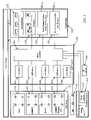
- FIG. 3is a functional block diagram of the electrical components, of one of the intelligent systems, using programmable digital control logic.
- FIG. 4is a flow chart illustrating use of an intelligent solid state lighting system, with the sensing and processing configured for occupancy detection and attendant control of the operation of the lighting system.
- FIGS. 5A and 5Bare simplified signal diagrams illustrating IR light levels and associated thresholds, useful in understanding an example of operation in accord with the process flow of FIG. 4 .
- FIG. 6is a diagram, illustrating a number of radiant energy emitting systems with common control from a master control unit.
- FIG. 7illustrates another example of an intelligent light emitting system, using fiber optic links from the LEDs to the optical integrating cavity.
- FIG. 8illustrates another example of an intelligent light emitting system, with certain elements thereof shown in cross-section.
- FIG. 9is a bottom view of the fixture in the system of FIG. 8 .
- FIGS. 10A to 10Care cross-sectional views of additional examples, of optical cavity LED light fixtures, with several alternative elements for processing of the combined light emerging from the cavity.
- FIG. 11illustrates another example of an intelligent light emitting system, utilizing principles of mask and cavity type constructive occlusion.
- FIG. 12is a bottom view of the fixture in the system of FIG. 10 .
- FIG. 13illustrates an alternate example of an intelligent light emitting system, utilizing principles of constructive occlusion.
- FIG. 14is a top plan view of the fixture in the system of FIG. 12 and associated detectors.
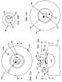
- FIG. 15Ais a cross-sectional view of another example of a light fixture, utilizing principles of mask-and-cavity constructive occlusion.
- FIG. 15Bis a cross-section of the fixture of FIG. 15A taken along line B-B.
- FIG. 16Aa top plan view of another example of a fixture, utilizing principles of mask-and-cavity constructive occlusion, having nested optical integrating cavities for emission and detection.
- FIG. 16Bis a cross-sectional view of the fixture of FIG. 16A , taken along line B-B.
- FIG. 16Cis a cross-sectional view of the fixture, taken along line C-C of FIG. 16B .
- FIG. 16Dis a cross-sectional view of the fixture, taken along line D-D of FIG. 16B .
- a lighting system as disclosed hereinincludes a chamber having a reflective interior surface. At least a portion of the interior surface has a diffuse reflectivity, such that the chamber combines light by diffuse reflection within the chamber.
- Typical examplesimplement the chamber as an optical integrating cavity.
- the chamberhas an optical aperture through which combined light emerges in a direction for lighting an area intended to be illuminated by the system.
- One or more solid state light emitting elementssupply light to the chamber. Each solid state light emitting element is coupled so as to supply light to the chamber in such a manner that substantially all light emitted from each solid state light emitting element reflects diffusely at least once within the interior of the chamber before combined light emission through the optical aperture toward the area intended to be illuminated by the system. Additional optical processing elements may process the combined light from the aperture.
- the optical processing by the chamber and other elementsconverts one or more solid state light sources of relatively small areas (“point sources”) into a virtual source of a larger area.
- the light outputforms a virtual source output in that the fixture or system output, e.g., at the optical aperture of the chamber or an output of a further optical processing element, forms the apparent source of light as perceived from the area that is being illuminated.
- Point source light generated by one or more solid state light emittersis not individually perceived as the source(s) of light from the perspective of the illuminated area. Instead, the virtual source appears as the single source of uniform light output over a larger output area.
- the systems disclosed hereinalso include a detector, for example as an integral element of a light fixture.
- the detectordetects electromagnetic energy from the area intended to be illuminated by the system, of a wavelength not present in (absent from) a spectrum of the combined light system output, that is to say generated by the solid state light emitter(s) and the chamber for the system's intended illumination application.
- the systemmay be passive, in that the detector detects light from within the area without itself supplying electromagnetic energy of the particular wavelength into the area.
- the systemmay be active, in that the system generates electromagnetic energy of the particular wavelength and the detector detects reflections of that electromagnetic energy from the illuminated area.
- the detector and sourcemay process to different wavelengths, e.g. for two-way communication.
- the detectormay be coupled to the chamber or a second chamber, or the detector may be outside the chamber.
- the sourcemay supply light through the chamber or it may be separate.
- a system controllerwill receive the signal from the detector.
- the controllerin some examples controls one or more aspects of operation of the solid state light emitter(s).
- the controllermay control lighting in response to the detector signal, for example by turning the solid state light emitter(s) on or off or otherwise controlling the amount of light energy output by each of the solid state light emitter(s).
- examplesare also discussed that use the detection signal for other purposes, for example, to capture data that may be carried on electromagnetic energy of the particular wavelength sensed by the detector.
- an exemplary lighting system 1 Aincludes an optical integrating cavity 2 having a reflective interior surface. At least a portion of the interior surface of the cavity 2 exhibits a diffuse reflectivity.
- the cavity 2may have various shapes. The illustrated cross-section would be substantially the same if the cavity is hemispherical or if the cavity is semi-cylindrical with a lateral cross-section taken perpendicular to the longitudinal axis. It is desirable that the cavity surface have a highly efficient reflective characteristic, e.g. a reflectivity equal to or greater than 90%, with respect to the relevant wavelengths.
- the entire interior surfacemay be diffusely reflective, or one or more substantial portions may be diffusely reflective while other portion(s) of the cavity surface may have different light responsive characteristics. In some examples, one or more other portions are substantially specular.
- the cavity 2 in the system 1 Ais assumed to be hemispherical.
- the optical cavity 2comprises a hemispherical dome 3 and a substantially flat cover plate 4 , with the reflective cavity formed between reflective surfaces of the dome 3 and plate 4 .
- At least the interior facing surface(s) of the dome 3 and possibly interior facing surface of the cover plate 4are highly diffusely reflective, so that the resulting cavity 2 is highly diffusely reflective with respect to the radiant energy spectrum produced by and/or detected by the system 1 A.
- the cavity 2is an integrating type optical cavity.
- the dome and platemay be formed as an integral unit.
- the cavity 2has an optical aperture 5 , which allows emission of reflected and diffused light C from within the interior of the cavity 2 into a region to facilitate a humanly perceptible lighting application for the system 1 A.
- the lighting system 1 Aalso includes at least one source of radiant electromagnetic energy for illumination purposes.
- the fixture geometry discussed hereinmay be used with any appropriate type of sources of radiant electromagnetic energy.
- sources of radiant electromagnetic energysuch as various conventional forms of incandescent, arc, neon and fluorescent lamp
- at least one sourcetakes the form of a solid state light emitting element (S), represented by the single solid state lighting element (S) 6 in the drawing.
- the element (S) 6typically emits visible light for illumination application.
- some source(s)may emit visible light and one or more other sources may emit light in another part of the electromagnetic spectrum.
- Each solid state light emitting element (S) 6is coupled to supply light to enter the cavity 2 at a point not directly observable through the aperture 5 from the region illuminated by the fixture output C.
- Various couplings and various light entry locationsmay be used.
- solid state light emitting elementsessentially include any of a wide range light emitting or generating devices formed from organic or inorganic semiconductor materials. Examples of solid state light emitting elements include semiconductor laser devices and the like. Many common examples of solid state lighting elements, however, are classified as types of “light emitting diodes” or “LEDs.” This exemplary class of solid state light emitting devices encompasses any and all types of semiconductor diode devices that are capable of receiving an electrical signal and producing a responsive output of electromagnetic energy. Thus, the term “LED” should be understood to include light emitting diodes of all types, light emitting polymers, organic diodes, and the like. LEDs may be individually packaged, as in the illustrated examples.
- LED based devicesmay be used that include a plurality of LEDs within one package, for example, multi-die LEDs that contain separately controllable red (R), green (G) and blue (B) LEDs within one package.
- LEDterminology does not restrict the source to any particular type of package for the LED type source. Such terms encompass LED devices that may be packaged or non-packaged, chip on board LEDs, surface mount LEDs, and any other configuration of the semiconductor diode device that emits light.
- Solid state lighting elementsmay include one or more phosphors and/or nanophosphors based upon quantum dots, which are integrated into elements of the package or light processing elements of the fixture to convert at least some radiant energy to a different more desirable wavelength or range of wavelengths.
- the color or spectral characteristic of light or other electromagnetic radiant energyrelates to the frequency and wavelength of the energy and/or to combinations of frequencies/wavelengths contained within the energy. Many of the examples relate to colors of light within the visible portion of the spectrum, although examples also are discussed that utilize or emit other energy.
- Electromagnetic energytypically in the form of light energy from the one or more solid state light sources (S) 6 , is diffusely reflected and combined within the cavity 2 to form combined light C for emission via the aperture 5 .
- Such integrationmay combine light from multiple sources. The integration tends to form a relatively Lambertian distribution across the aperture. When viewed from the area illuminated by the combined light C, the aperture appears to have substantially infinite depth of the integrated light C.
- the visible intensityis spread uniformly across the aperture, as opposed to individual small point sources of higher intensity as would be seen if the one or more elements (S) 6 were directly visible without diffuse reflection before emission through the aperture 5 .
- the light output Cappears to emanate from a virtual source, at the aperture 5 in this example.
- Pixelationis a problem with many prior solid state lighting devices.
- the light output from individual LEDs or the likeappear as identifiable/individual point sources or ‘pixels.’
- the pixels of the sourcesare apparent.
- the observable output of such a prior systemexhibits a high maximum-to-minimum intensity ratio.
- the light from the fixtureoften exhibits striations of different colors.
- the cavity output Cappears as unpixelated virtual source of relatively uniform intensity distribution across the apparent output area of the fixture, e.g. across the optical aperture 5 of the cavity 2 .
- the optical integrationsufficiently mixes the light from the solid state light emitting elements 6 that the combined light output C of the virtual source is at least substantially Lambertian in distribution across the optical output area of the fixture, that is to say across the aperture 5 of the cavity 2 .
- the combined light output Cexhibits a relatively low maximum-to-minimum intensity ratio across the aperture 5 .
- the combined light outputexhibits a maximum to minimum ratio of 2 to 1 or less over substantially the entire optical output area.
- solid state light emitting elements 6may be configured to generate electromagnetic radiant energy having various bandwidths for a given spectrum (e.g. narrow bandwidth of a particular color, or broad bandwidth centered about a particular), and may use different configurations to achieve a given spectral characteristic.
- a white LEDmay utilize a number of dies that generate different primary colors which combine to form essentially white light.
- a white LEDmay utilize a semiconductor that generates light of a relatively narrow first spectrum in response to an electrical input signal, but the narrow first spectrum acts as a pump. The light from the semiconductor “pumps” a phosphor material contained in the LED package, which in turn radiates a different typically broader spectrum of light that appears relatively white to the human observer.
- the system 1 Aalso includes a controller, shown in the example as a control circuit 7 , which is responsive to a user actuation for controlling an amount of radiant electromagnetic energy supplied to the cavity 2 by the solid state light emitting element or elements 6 of the system 1 A.
- the control circuit 7typically includes a power supply circuit coupled to a power source, shown as an AC power source 8 .
- the control circuit 7also includes one or more adjustable driver circuits for controlling the power applied to the solid state light emitting elements (S) 6 and thus the amount of radiant energy supplied to the cavity 2 by each source 6 .
- the control circuit 7may be responsive to a number of different control input signals, for example, to one or more user inputs as shown by the arrow in FIG. 1A and possibly signals from one or more feedback sensors, as discussed in more detail later.
- the virtual source output light Chas a spectral characteristic, typically in the visible light region of the spectrum.
- the system 1 Aalso includes a detector 9 .
- the detector 9senses a characteristic of electromagnetic energy reflected within the cavity 5 .
- the detector 9is a device of a type for sensing at least one wavelength of light not present in the spectrum of light output C from the aperture 5 that forms the virtual source in this example.
- the wavelengthmay be a visible wavelength corresponding to a notch in the visible spectrum of output light C.
- the wavelength sensed by detector 9is a wavelength outside the visible spectrum, for example in the near or far infrared (IR) range or in the ultraviolet (UV) range.
- the detector 9senses a wavelength not present in the spectrum of light output C and thus absent from the light generated by the solid state source 6 , the detector 9 is responsive to energy of that wavelength that enters the cavity 2 via the aperture 5 and reflects off the surface(s) of the cavity.
- the detector 9supplies a detection signal to the controller 7 .
- the controller 7may control one or more operations of the system 1 A in response to the detection signal, for example to turn the light output C ON and OFF or to vary the intensity of the output (while ON).
- the controller 7may process the signal for other purposes, e.g. to demodulate the signal to capture data that may be carried on the energy of the particular wavelength.
- the detector 9is coupled to a location in the optical integrating cavity 2 at which at least a substantial portion of the electromagnetic energy of the particular wavelength that enters the cavity 2 through the optical aperture 5 is reflected one or more times off the reflective interior surface of the cavity 2 before reaching the location of coupling to the detector 9 .
- the detector 9may be at or otherwise coupled to any such point on a surface of the cavity 2 , typically a point not directly visible or illuminated through the aperture 5 .
- the detector 9is mounted to receive light at a point on the plate 4 .
- the apertureforms a virtual output source, it also forms a virtual detector surface.
- the optical processing of light before sensing by the detectormakes the system uniformly sensitive at points on the aperture.
- the apertureis a substantially Lambertian detecting surface.
- the system 1 Auses an active sensing approach, in that the system 1 A also includes a source 10 of electromagnetic energy of the wavelength sensed by detector 9 .
- the source 10may be another solid state light emitter similar to the source 6 , but configured to emit a wavelength not present in the output light C. It is also envisaged that the source 10 may be any other conventional source of electromagnetic energy (such as an incandescent lamp, a fluorescent lamp, an arc lamp, a halogen lamp, etc.) as long as the particular source 10 provides electromagnetic energy of the appropriate wavelength.
- the detectoris outside the cavity, and the source 10 is coupled to supply light into the interior of the optical integrating cavity, in a manner similar to the solid state light source (S) 6 .
- the source 10is located for emission of electromagnetic energy of the particular wavelength from outside the optical integrating cavity 2 into at least a portion of the area intended to be illuminated by the virtual source light output C, that is to say without passage of the energy from the source 10 through the optical aperture 5 .
- the source 10may be mounted close to the cavity 2 and may be an integral part of a fixture that includes the cavity, the solid state light source (S) 6 and the detector 9 .
- the source 10may located at any other convenient position from which it may illuminate at least a portion of the area that the system 1 A is intended to illuminate with the light output C.
- the electromagnetic energy from the source 10reflects back from one or more objects in the area illuminated by the system 1 A. At least a portion of the reflected energy enters the optical integrating cavity 2 via the aperture 5 . Such electromagnetic energy reflects one or more times off of the surfaces of the dome 3 and plate 4 that form the cavity 2 . One or more such reflections will diffuse the reflected electromagnetic energy. At least a portion of the electromagnetic energy of the particular wavelength, that is diffusely reflected within the cavity 2 , is coupled to and sensed by detector 9 . In response, the detector 9 generates a signal that relates to the measured or sensed amount of that electromagnetic energy.
- FIG. 1Bshows another example of an intelligent lighting system, that is to say system 1 B.
- the system 1 Bfor example, includes an optical integrating cavity 2 similar to that discussed above relative to FIG. 1A .
- the cavity 2 formed in the example by the dome 3 and the cover plate 4has a reflective interior. At least one surface of the interior of the cavity 2 is diffusely reflective, so that the cavity diffusely reflects light and thereby integrates or combines light.
- the cavity 2has an optical aperture for allowing emission of reflected light from within the interior of the cavity as combined light C directed into a region to facilitate a humanly perceptible lighting application for the system 1 B.
- the integration in the cavity 2effectively produces a virtual source of the output light C, in this case, again at the aperture 5 .
- solid state light emitting elements (S) 6for emitting light, similar to the element(s) 6 used in the system 1 A of FIG. 1A . At least one of the solid state light emitting elements 6 emits visible light energy. The other emitting element 6 typically emits visible light energy, although in some case the other element may produce other spectrums, e.g. in the ultraviolet (UV) or infrared (IR) portions of the electromagnetic spectrum. Each of the solid state light emitting elements (S) 6 supplies light (visible, UV or IR) into the cavity 2 at a point not directly observable through the aperture from the region.
- UVultraviolet
- IRinfrared
- the system 1 Bcould include a source of the additional wavelength, similar to the source 10 in the system 1 A of FIG. 1A . However, in this example, the system does not include such an additional source.
- the system 1 Bmay also include a user interface device for providing the means for user input.
- the virtual source output light Chas a spectral characteristic, typically in the visible light region of the spectrum.
- the system 1 Balso includes a detector 9 , for sensing a characteristic of electromagnetic energy reflected within the cavity 5 ; and the detector 9 is a device of a type for sensing at least one wavelength of light not present in the spectrum of light generated for output C from the aperture 5 that forms the virtual source in this example.
- the wavelengthmay be a visible wavelength corresponding to a notch in the visible spectrum of output light C.
- the wavelength sensed by detector 9is a wavelength outside the visible spectrum, for example in the near or far infrared (IR) range or in the ultraviolet (UV) range.
- the detector 9senses a wavelength not present in the spectrum of light output C and thus absent from the light generated by the solid state source 6 , the detector 9 is responsive to energy of that wavelength that enters the cavity 2 via the aperture 5 and reflects off the surface(s) of the cavity.
- the system 1 Buses a passive sensing approach, in that the system 1 B relies on sensing of electromagnetic energy of the particular wavelength emitted or reflected from other sources within the illuminated area, without the system 1 B itself supplying energy of that wavelength.
- the sensor 9may passively detect IR from one or more heat sources within a room illuminated by the system 1 B, such as one or more persons who enter the room.
- the detector 9is coupled to a location in the optical integrating cavity 2 at which at least a substantial portion of the electromagnetic energy of the particular wavelength that enters the cavity 2 through the optical aperture 5 is reflected one or more times off the reflective interior surface of the cavity 2 before reaching the location of coupling to the detector 9 .
- One or more of the reflectionswill diffuse the reflected electromagnetic energy.
- the detector 9may be located at or otherwise coupled to any such point on a surface of the cavity 2 , typically a point not directly visible or illuminated through the aperture 5 .
- the detector 9is mounted to receive light at a point on the plate 4 .
- the detector 9At least a portion of the electromagnetic energy of the particular wavelength, that is diffusely reflected within the cavity 2 , is coupled to and sensed by detector 9 .
- the detector 9generates a signal that relates to the measured or sensed amount of that electromagnetic energy.
- the detector 9supplies the detection signal to the controller 7 ; and the controller 7 may control one or more operations of the system 1 B in response to the detection signal.
- the controller 7may process the signal for other purposes, e.g. to demodulate the signal to capture data that may be carried on the energy of the particular wavelength.
- the controllermight modulate the drive of the emitters 6 with downlink data, and the light sensed by the detector 9 would carry the uplink data.
- Some systems that use multiple solid state light emitting elements (S) 6may use sources 6 of the same type, that is to say a set of solid state light emitting sources of a type intended to all produce electromagnetic energy of substantially the same spectral characteristic (assuming the same or similar supply of power). All of the sources may be identical white light (W) emitting elements or may all emit light of the same primary color.
- the system 1 CFIG. 1C ) includes multiple white solid state emitting (S) 6 1 and 6 2 . Although the two white light emitting elements could emit the same color temperature of white light, in this example, the two elements 6 emit white light of two different color temperatures.
- the system 1 Cis generally similar to the system 1 A discussed above, and similarly numbered elements have similar structures, arrangements and functions.
- the first solid state light emitting element 6 1is a white LED W 1 of a first type, for emitting white light of a first color temperature
- the second solid state light emitting element 6 2is a white LED W 2 of a second type, for emitting white light of a somewhat different second color temperature.
- Controlled combination of the two types of white light within the cavity 2allows for some color adjustment, to achieve a color temperature of the combined light output C that is somewhere between the temperatures of the two white lights, depending on the amount of each white light provided by the two elements 6 1 and 6 2 .
- the system 1 Cimplements a passive detection scheme, similar to that of the system 1 B of FIG. 1B .
- the system 1 Cincludes a detector 9 coupled to the cavity 2 to receive electromagnetic energy of the particular wavelength after diffuse reflection within the cavity 2 .
- the detector 9would be a type of device that is sensitive to one or more wavelengths outside the visible portion of the spectrum, e.g. for sensing near or far IR light or UV light.
- FIG. 1Dillustrates another system example 1 D.
- the system 1 Dis similar to the system 1 C discussed above, and similarly numbered elements have similar structures, arrangements and functions.
- the multiple solid state light emitting elements 6 3are white light emitters of the same type. Although the actual spectral output of the emitters 6 3 may vary somewhat from device to device, the solid state light emitting elements 6 3 are of a type intended to emit white light of substantially the same color temperature.
- the diffuse processing and combination of light from the solid state white light emitting elements 6 3provides a virtual source of uniform white light output over the area of the aperture 5 , much like in the other embodiment of FIG. 1C . However, because the emitting elements 6 3 all emit white light of substantially the same color temperature, the combined light C also has substantially the same color temperature.
- the solid state light emitting elements 6represent point sources.
- the actual area of light emission from each element 6is relatively small.
- the actual light emitting chip areamay be only a few square millimeters or less in area.
- the LED packagingoften provides some diffusion, but this only expands the source area a bit, to tens or hundreds of millimeters. Such a concentrated point source output may be potentially hazardous if viewed directly. Where there are multiple solid state sources, when viewed directly, the sources appear as multiple bright light point sources.
- the processing within the cavity 2combines and spreads the light from the solid state light emitting elements 6 for virtual source output via the much larger area of the aperture 5 .
- An aperture 5 with a two (2) inch radiusrepresents a virtual source area of 12.6 square inches. Although the aperture 5 may still appear as a bright virtual light source, the bright light over the larger area will often represent a reduced hazard.
- the integration by the optical cavityalso combines the point source light to form a uniform distribution at the virtual source. The uniform distribution extends over the optical output area of the virtual source, the area of aperture 5 in the example, which is larger than the combined areas of outputs of the point sources of light from the solid state emitters 6 .
- the cavity 2serves as an optical processing element to diffuse the light from the solid state light emitting element 6 over the virtual source output area represented by the aperture 5 , to produce a light output through the optical output area that is sufficiently uniform across the virtual source area as to appear as an unpixelated light output.
- the system 1 Dimplements a passive detection scheme, similar to that of the system 1 B of FIG. 1B .
- the system 1 Dincludes a detector 9 coupled to the cavity 2 to receive electromagnetic energy of the particular wavelength after diffuse reflection within the cavity 2 .
- the detector 9would be a type of device that is sensitive to one or more wavelengths outside the visible portion of the spectrum, e.g. for sensing near or far IR light or UV light.
- FIGS. 1E and 1Fillustrate additional system examples, which include at least one solid state light emitting element for emitting light outside the visible portion of the electromagnetic spectrum.
- the system 1 Eis similar to the systems discussed above, and similarly numbered elements have similar structures, arrangements and functions.
- one solid state light emitting element 6 4emits visible light
- another solid state light emitting element 6 5emits ultraviolet (UV) light.
- the cavity 2reflects, diffuses and combines visible and UV light from the solid state light emitting element 6 4 and 6 5 , in essentially the same manner as in the earlier visible light examples.
- the systemalso includes a detector 9 .
- the source 9may be sensitive to energy of the wavelength produced by the UV source 6 5 , as that energy includes one or more light wavelengths outside the spectrum produced by the source 6 4 used for the visible illumination application.
- the source 6 5is coupled to supply electromagnetic energy of the particular wavelength into the optical integrating cavity 2 in such a manner that substantially all energy of that wavelength emitted from the source 6 5 reflects diffusely at least once within the interior of the optical integrating cavity 2 before emission with the diffusely reflected visible light C through the optical aperture 5 toward the region or area to be illuminated by the system 1 E.
- the detector 9could not sense reflected light of that wavelength coming back from the illuminated region.
- the detector 9 in this exampleis located separately and not coupled to the cavity 2 .
- the detector 9detects reflected UV electromagnetic energy from the illuminated region. After reflection off of a person or object in the region, the reflected UV light reaches the detector 9 without passage of the reflected UV light energy through the optical aperture 5 .
- the system 1 Fis similar to the systems discussed above, particularly the system 1 B of FIG. 1B , and similarly numbered elements have similar structures, arrangements and functions.
- one solid state light emitting element 6 6emits visible light for visible illumination or other lighting applications
- another solid state light emitting element 6 7emits infrared (IR) light.
- the IR light from element 6 7is outside the spectrum of light produced by the solid state light emitting element 6 6 .
- the cavity 2reflects, diffuses and combines visible and IR light from the solid state light emitting elements 6 6 and 6 7 in essentially the same manner as in the earlier examples.
- the detector 9 in this exampleis mounted separately so as to not receive light via the cavity 2 . Instead, the detector 9 detects reflected or separately generated electromagnetic energy from the illuminated region. After reflection off of a person or object in the region, the reflected light reaches the detector 9 without passage of the reflected light energy through the optical aperture 5 .
- the detector 9could detect a wavelength of visible light that is absent from the light produced by source 6 6 , the detector 9 may detect IR light produced by source 6 7 reflected back from persons or objects within the area illuminated by the system 1 F, or the detector 9 may detect IR or other light of a wavelength different from that produced by source 6 7 .
- the detector 9would typically detect IR light of the same wavelength(s) as produced by the solid state light emitting element 6 7 . If the reflected IR light of that spectral characteristic from the illuminated region changes by a predetermined amount, the controller would change the operating condition/state of the system 1 F.
- IR detectionwhether passive or active, can be used as an occupancy detection. When a person enters the illuminated area (when previously unoccupied), the controller turns ON the visible light emissions or turns-up the intensity. The controller keeps the visible light ON while the area is occupied. After all persons leave, and the area is unoccupied for more than some minimal time, the controller turns down or OFF the visible light output.
- the illustrated IR emission and detection of FIG. 1Fmay be used in a different manner, for data communications. It is possible to modulate the operations of the IR solid state light emitting element 6 7 to carry data. Typically, the IR solid state light emitting element 6 7 would emit modulated light of a first infrared wavelength. A receiver (not shown) in the illuminated area would pick up that light, demodulate it and recover the data. The detector 9 in turn would sense IR light of a second infrared wavelength that is different from the first infrared wavelength. In this way, the detector would not be sensitive to reflections of the modulated IR light from the light emitting element 6 7 . The detector 9 would supply its sensing signal to the control circuit 7 .
- controlmight control system operation in response to that signal, assume now that the control processes the signal for a different purpose, to recover data.
- a transmitter(not shown) would modulate IR light of the wavelength that the detector 9 is configured to sense with data.
- the detection signal from the detector 9could be demodulated to capture that data.
- the data communications capabilities offered by the IR solid state light emitting element 6 7 and the IR sensitive detector 9could be used for two-way communication of data regarding system operation, e.g. remote control and associated responsive signaling. However, these communications could enable use of the system for more general two-way data communications, e.g. as a two-way wireless interface to a data network.
- the detector 9is shown as a separate element for sensing light reflected or generated in the illuminate region without passing through the aperture from the reflection point or source. However, if there is sufficient wavelength separation between the wavelength emitted by light emitting element 6 7 and the wavelength sensed by the detector 9 , the detector 9 would be coupled to receive light reflected within the cavity, in a manner similar to that in the example of FIG. 1 .
- sources of two, three or more different types of light sourcesthat is to say solid state light sources that produce electromagnetic energy of two, three or more different spectral characteristics.
- Many such examplesinclude sources of visible red (R) light, visible green (G) light and visible blue (B) light or other combinations of primary colors of light. Controlled amounts of light from primary color sources can be combined to produce light of many other visible colors, including various temperatures of white light. It may be helpful now to consider several more detailed examples of lighting systems using solid state light emitting elements. A number of the examples, starting with that of FIG. 2 use RGB LEDs or similar sets of devices for emitting three or more colors of visible light for combination within the optical integrating cavity and virtual source emission.
- FIG. 2is a cross-sectional illustration of a radiant energy distribution apparatus or system 20 .
- the apparatusemits light in the visible spectrum, although the system 20 may be used for lumination applications and/or with emissions in or extending into the infrared and/or ultraviolet portions of the radiant energy spectrum.
- the illustrated system 20includes an optical cavity 11 having a diffusely reflective interior surface, to receive and diffusely process radiant energy of different colors/wavelengths.
- the cavity 11may have various shapes.
- the illustrated cross-sectionwould be substantially the same if the cavity 11 is hemispherical or if the cavity is semi-cylindrical with the cross-section taken perpendicular to the longitudinal axis.
- the optical cavity 11 in the examples discussed belowis typically an optical integrating cavity.
- the disclosed apparatusmay use a variety of different structures or arrangements for the optical integrating cavity, several examples of which are discussed below. At least a substantial portion of the interior surface(s) of the cavity exhibit(s) diffuse reflectivity. It is desirable that the cavity surface have a highly efficient reflective characteristic, e.g. a reflectivity equal to or greater than 90%, with respect to the relevant wavelengths. In the example of FIG. 2 , the surface is highly diffusely reflective to energy in the visible, near-infrared, and ultraviolet wavelengths.
- the cavity 11may be formed of a diffusely reflective plastic material, such as a polypropylene having a 97% reflectivity and a diffuse reflective characteristic.
- a diffusely reflective plastic materialsuch as a polypropylene having a 97% reflectivity and a diffuse reflective characteristic.
- a highly reflective polypropyleneis available from Ferro Corporation—Specialty Plastics Group, Filled and Reinforced Plastics Division, in Evansville, Ind.
- Another example of a material with a suitable reflectivityis SPECTRALON.
- the optical integrating cavitymay comprise a rigid substrate having an interior surface, and a diffusely reflective coating layer formed on the interior surface of the substrate so as to provide the diffusely reflective interior surface of the optical integrating cavity.
- the coating layerfor example, might take the form of a flat-white paint or white powder coat.
- a suitable paintmight include a zinc-oxide based pigment, consisting essentially of an uncalcined zinc oxide and preferably containing a small amount of a dispersing agent.
- the pigmentis mixed with an alkali metal silicate vehicle-binder, which preferably is a potassium silicate, to form the coating material.
- an alkali metal silicate vehicle-binderwhich preferably is a potassium silicate
- the cavity 11 in the apparatus 20is assumed to be hemispherical.
- a hemispherical dome 13 and a substantially flat cover plate 15form the optical cavity 11 .
- At least the interior facing surfaces of the dome 13 and the cover plate 15are highly diffusely reflective, so that the resulting cavity 11 is highly diffusely reflective with respect to the radiant energy spectrum produced by the device 20 .
- the cavity 11is an integrating type optical cavity.
- the dome and platemay be formed as an integral unit.
- rectangular cavitiesare contemplated, in which the dome and plate are elements of a unitary extruded member.
- the optical integrating cavity 11has an aperture 17 for allowing emission of combined radiant energy.
- the optical aperture 17is a passage through the approximate center of the cover plate 15 , although the aperture may be at any other convenient location on the plate 15 or the dome 13 .
- this diffuse processing of lightproduces a virtual light source at the aperture 17 . If as illustrated the actual sources emit light of two or more different colors, the virtual source appears as a source of a color of light that results from the combination of the colors from the actual sources.
- the integrationproduces a highly uniform light distribution across the aperture 17 of the cavity 11 , which forms the virtual output area and often forms all or a substantial part of the output area of the fixture.
- the distribution of light across the aperture 17is substantially Lambertian.
- the aperture 17appears to be a light source of substantially infinite depth of the combined color of light.
- the visible intensityis spread uniformly across the aperture 17 , as opposed to individual small point sources as would be seen if the one or more of the light emitting elements were directly visible. This conversion to a virtual source, by spreading of the light over the aperture area, reduces or eliminates hazards from direct view of intense solid state point sources.
- the virtual source fixture outputis relatively uniform across the apparent output area of the virtual source, e.g. across the optical aperture 17 of the cavity 11 .
- the virtual source light outputexhibits a relatively low maximum-to-minimum intensity ratio across the area of the aperture 17 .
- the virtual source light outputexhibits a maximum-to-minimum ratio of 2 to 1 (2:1) or less over substantially the entire virtual source optical output area represented by the aperture 17 .
- the apparatus 20is shown emitting the radiant energy downward from the virtual source, that is to say downward through the aperture 17 , for convenience.
- the apparatus 20may be oriented in any desired direction to perform a desired application function, for example to provide visible luminance to persons in a particular direction or location with respect to the fixture or to illuminate a different surface such as a wall, floor or table top.
- the optical integrating cavity 11may have more than one aperture 17 , for example, oriented to allow emission of integrated light in two or more different directions or regions.
- the apparatus 20also includes solid state light emission sources of radiant energy of different wavelengths.
- the solid state sourcesare LEDs 19 , two of which are visible in the illustrated cross-section.
- the LEDs 19supply radiant energy into the interior of the optical integrating cavity 11 .
- the points of emission into the interior of the optical integrating cavityare not directly visible through the aperture 17 .
- Direct emissions from the LEDs 19are directed toward the diffusely reflective inner surface of the dome 13 , so as to diffusely reflect at least once within the cavity 11 before emission in the combined light passing out of the cavity through the aperture 17 .
- At least the two illustrated LEDs 19emit radiant energy of different wavelengths, e.g. Red (R) and Green (G). Additional LEDs of the same or different colors may be provided.
- the cavity 11effectively integrates the energy of different wavelengths, so that the integrated or combined radiant energy emitted through the aperture 17 forms a virtual source of light that includes the radiant energy of all the various wavelengths in relative amounts substantially corresponding to the relative amounts of input into the cavity 11 from the respective LEDs 19 .
- the source LEDs 19can include LEDs of any color or wavelength.
- an array of primary color LEDs for a visible light applicationincludes at least red, green, and blue LEDs.
- the integrating or mixing capability of the cavity 11serves to project light of any color, including white light, by adjusting the intensity of the various sources coupled to the cavity. Hence, it is possible to control color rendering index (CRI), as well as color temperature.
- CRIcolor rendering index
- the system 20works with the totality of light output from a family of LEDs 19 . However, to provide color adjustment or variability, it is not necessary to control the output of individual LEDs, except as they contribute to the totality. For example, it is not necessary to modulate the LED outputs, although modulation may be used if desirable for particular applications. Also, the distribution pattern of the individual LEDs and their emission points into the cavity are not significant.
- the LEDs 19can be arranged in any manner to supply radiant energy within the cavity, although it is preferred that direct view of the LEDs from outside the fixture is minimized or avoided.
- light outputs of the LED sources 19are coupled directly to openings at points on the interior of the cavity 11 , to emit radiant energy directly into the interior of the optical integrating cavity.
- Direct emissionsare aimed at a reflective surface of the cavity.
- the LEDs 19may be located to emit light at points on the interior wall of the element 13 , although preferably such points would still be in regions out of the direct line of sight through the aperture 17 .
- the openings for the LEDs 19are formed through the cover plate 15 . On the plate 15 , the openings/LEDs may be at any convenient locations. From such locations, all or substantially all of the direct emissions from the LEDs 19 impact on the internal surface of the dome 13 and are diffusely reflected.
- the exemplary system 20also includes a sensor or detector 16 , for sensing a characteristic of the reflected light from within the interior of the cavity 11 .
- the sensor 16may detect intensity of the combined light in the cavity 11 .
- the sensormay provide some indication of the spectral characteristic of the combined light in the cavity 11 .
- the detector 16operates as a feedback sensor, for use in controlling system operations. Although the detector 16 could also sense intensity of one or more additional wavelengths (analogous to operation of detector 9 in the earlier examples), typically, the intensity and/or spectral characteristic sensed by detector 16 is that of the light produced by the diffuse processing of the light from the LEDs 19 within the cavity 11 for the illumination application. In such arrangements, the signal from the detector 16 is used for feedback purposes.
- the exemplary system 20also includes a sensor or detector 18 for detecting an amount (e.g. intensity) of electromagnetic energy of a wavelength that is absent from the light produced by the LEDs 19 and/or the diffuse processing of the light from the LEDs 19 within the cavity 11 .
- the RGB LEDs 19produce visible light
- the combined light produced by diffuse reflection of the light from the LEDs 19 within the cavity 11is visible light. It is intended that adjustment of the amounts of light from the LEDs will enable selection of the spectral characteristic of the visible light output of the system over a substantial range of the visible light portion of the electromagnetic spectrum.
- the detector 18is of a type or configuration for sensing at least one wavelength outside of the visible light portion of the electromagnetic spectrum.
- the detector 18might sense UV light or other non-visible wavelengths, in the example of system 20 , the detector 18 senses IR light energy in the near IR range or in the far IR range.
- the detector 18is coupled to receive light from within or on a wall of the cavity 11 so that the detector 18 senses a characteristic of electromagnetic energy diffusely reflected within the cavity 11 .
- the detectormay be located at or otherwise coupled to any convenient point on or within the cavity 11 , although typically the point is on a wall of the cavity and located so that light entering through the aperture 17 reflects diffusely one or more times within the cavity before reaching the point of coupling to the detector 18 . Since the detector 18 senses a wavelength not present in the spectrum of light output by the LEDs 19 , the detector 18 is responsive to energy of that wavelength that enters the cavity 11 via the aperture 17 and reflects off the surface(s) of the cavity 11 .
- the apparatus 20also includes a control circuit 21 coupled to the LEDs 19 for establishing output intensity of radiant energy of each of the LED sources.
- the control circuit 21is responsive to detection signals supplied by the detectors 16 and 18 .
- the control circuit 21typically includes a power supply circuit coupled to a source, shown as an AC power source 23 .
- the control circuit 21also includes an appropriate number of LED driver circuits for controlling the power applied to each of the different color LEDs 19 and thus the amount of radiant energy supplied to the cavity 11 for each different wavelength. It is possible that the power could be modulated to control respective light amounts output by the LEDs 19 , however, in the examples, LED outputs are controlled by controlling the amount of power supplied to drive respective LEDs.
- control circuit 21may be responsive to a number of different control input signals, for example, to one or more user inputs as shown by the arrow in FIG. 2 . Specific examples of the control circuitry are discussed in more detail later.
- the system 20also includes a source 24 of IR light, that is to say of at least one wavelength absent from the light produced by the LEDs 19 and the combined light output emitted through the aperture 17 .
- the source 24may emit light of a different wavelength from that sensed by the detector 18 , as discussed earlier, but in this example, the IR source 24 emits light of a wavelength that the detector 18 will sense.
- the IR source 24may be mounted on or near the fixture but outside the cavity 11 , or the IR source 24 may be mounted at a different location.
- the IR sourcecould be directed from the illuminated area toward the aperture for some applications; but in the example, the source 24 is oriented to direct its output away from the fixture and into a portion of the area illuminated by the fixture. Hence, the IR light from the source 24 illuminates at least a portion of a region intended to be illuminated by the combined light output from the aperture 17 .
- One or more additional sources 24may also be provided.
- the aperture 17may serve as the system output, directing integrated color light of relatively uniform intensity distribution to a desired area or region to be illuminated.
- the aperture 17may have a grate, lens or diffuser (e.g. a holographic element) to help distribute the output light and/or to close the aperture against entry of moisture of debris.
- the system 20includes an additional downstream optical processing element, such as deflector, diffuser, filter or the like.
- the exemplary apparatus 20 shown in FIG. 2comprises a deflector 25 , as the additional optical processing element.
- the deflector 25has a reflective inner surface 29 , to efficiently direct most of the light emerging from a light source at aperture C into a relatively narrow field of view.
- a small opening at a proximal end of the deflectoris coupled to the aperture 17 of the optical integrating cavity 11 .
- the deflector 25has a larger opening 27 at a distal end thereof.
- the deflector 25is conical.
- the angle and distal opening of the conical deflector 25define an angular field of radiant energy emission from the apparatus 20 .
- the large opening of the deflectormay be covered with a transparent plate or lens, or covered with a grating, to prevent entry of dirt or debris through the cone into the system and/or to further process the output radiant energy.
- the deflector 25may have a variety of different shapes, depending on the particular lighting application.
- the cross-section of the conical deflectoris typically circular.
- the deflectormay be somewhat oval in shape.
- the deflectormay be elongated or even rectangular in cross-section.
- the shape of the aperture 17also may vary, but will typically match the shape of the small end opening of the deflector 25 . Hence, in the example, the aperture 17 would be circular.
- the aperturemay be rectangular.
- the deflector 25comprises a reflective interior surface 29 between the distal end and the proximal end. In some examples, at least a substantial portion of the reflective interior surface 29 of the conical deflector exhibits specular reflectivity with respect to the integrated radiant energy. As discussed in U.S. Pat. No. 6,007,225, for some applications, it may be desirable to construct the deflector 25 so that at least some portion(s) of the inner surface 29 exhibit diffuse reflectivity or exhibit a different degree of specular reflectivity (e.g., quasi-secular), so as to tailor the performance of the deflector 25 to the particular application. For other applications, it may also be desirable for the entire interior surface 29 of the deflector 25 to have a diffuse reflective characteristic. In such cases, the deflector 25 may be constructed using materials similar to those taught above for construction of the optical integrating cavity 11 .
- the large distal opening 27 of the deflector 25is roughly the same size as the cavity 11 . In some applications, this size relationship may be convenient for construction purposes. However, a direct relationship in size of the distal end of the deflector and the cavity is not required. The large end of the deflector may be larger or smaller than the cavity structure. As a practical matter, the size of the cavity is optimized to provide the integration or combination of light colors from the desired number of LED sources 19 . The size, angle and shape of the deflector determine the area that will be illuminated by the combined or integrated light emitted from the cavity 11 via the aperture 17 and the field of view of the cavity for purposes of receiving IR light for sensing by detector 18 .
- each solid state source of radiant energy of a particular wavelengthcomprises one or more light emitting diodes (LEDs).
- the sourcesmay comprise one or more LEDs for emitting light of a first color, and one or more LEDs for emitting light of a second color, wherein the second color is different from the first color.
- Each LEDrepresents a point source of a particular color, which in the RGB example, is one of three primary colors.
- the diffuse processingconverts the point source lights to a single combined virtual source light at the aperture.
- the apparatusmay include additional sources comprising one or more LEDs of a third color, a fourth color, etc.; and the diffuse processing combines those additional lights into the virtual source light output.
- the LED arraymay include LEDs of various wavelengths that cover virtually the entire visible spectrum. Examples with additional sources of substantially white light are discussed later.
- Each of the detectors 16 and 18supplies a detection signal to the control circuit 21 .
- the detector 16provides feedback as to the operation of the system 20 , and the controller in circuit 21 uses that signal to adjust one or more operation parameters of the LED outputs, in a manner intended to achieve and maintain intensity and/or color output settings.
- the detector 18senses an amount of energy of the particular wavelength that is received back from the illuminated area and reflected within the cavity 11 .
- the controllercould process or use the signal in other ways (e.g. to receive data for remote control or communication purposes), in this example, the controller 21 controls one or more operations of the system 20 in response to the detection signal from the detector 18 .
- the IR light from source 24 and the attendant IR reflection sensed by detector 18may provide a system for active detection of whether or not the area illuminated by the system is occupied.
- the control circuit 21can turn the LEDs 19 ON and OFF, or the controller may vary the amount of output (while ON) of one or more colors of LEDs to adjust the output intensity and/or color in some manner.
- control circuitrycomprises a color feedback sensor coupled to detect color distribution in the integrated radiant energy.
- Associated logic circuitryresponsive to the detected color distribution, controls the output intensity of the various LEDs, so as to provide a desired color distribution in the integrated radiant energy.
- the logic circuitryis responsive to the detected color distribution to selectively activate the inactive light emitting diodes as needed, to maintain the desired color distribution in the integrated radiant energy.
- the inventive deviceshave numerous applications, and the output intensity and spectral characteristic may be tailored and/or adjusted to suit the particular application.
- the intensity of the integrated radiant energy emitted through the aperturemay be at a level for use in a luminance application or at a level sufficient for a task lighting application or other type of general lighting application.
- the control circuit 21may turn ON/OFF the LEDs based on occupancy in response to the signal from detector 18 , but while ON, maintain a set color characteristic in response to color feedback from a sensor 16 .
- the control circuitry 21may also include a temperature sensor. In such an example, the logic circuitry is also responsive to the sensed temperature, e.g. to reduce intensity of the source outputs to compensate for temperature increases.
- the control circuitry 21may include a user interface device or receive signals from a separate user interface device, for manually setting the desired spectral characteristic.
- a user interface deviceor receive signals from a separate user interface device, for manually setting the desired spectral characteristic.
- an integrated user interfacemight include one or more variable resistors or one or more dip switches directly connected into the control circuitry, to allow a user to define or select the desired color distribution and/or intensity.
- control circuitrymay include a data interface coupled to the logic circuitry, for receiving data defining the desired intensity and/or color distribution.
- a data interfacecoupled to the logic circuitry, for receiving data defining the desired intensity and/or color distribution.
- Such an interfacewould allow input of control data from a separate or even remote device, such as a personal computer, personal digital assistant or the like.
- a number of the devices, with such data interfaces,may be controlled from a common central location or device.
- Such a communication interface to the control circuitrymay also provide a link to a network, e.g. when the source 24 and detector 18 are used for two-way IR transport of wireless data signals.
- the controlmay be somewhat static, e.g. to set the desired color reference index or desired color temperature and the overall intensity, and leave the device set-up in that manner for an indefinite period unless or until a detected change in occupancy status.
- the apparatusalso may be controlled dynamically, for example, to provide special effects lighting.
- dynamic control of color and intensity of each unitcould even provide a video display capability, for example, for use as a “Jumbo Tron” view screen in a stadium or the like.
- product lighting or in personnel lightingfor studio or theater work
- the lightingcan be adjusted for each product or person that is illuminated. Also, such light settings are easily recorded and reused at a later time or even at a different location using a different system.
- FIG. 3is a block diagram of exemplary circuitry for the sources and associated control circuit, providing digital programmable control, which may be utilized with a light integrating fixture of the type described above.
- the illustrated circuitryalso includes an IR source and IR detector corresponding to those of the system 20 of FIG. 2 , although similar circuitry could be used with sources and detectors for emitting/sensing other wavelengths as outlined in several of the examples above.
- the solid state sources of radiant energy of the various typestake the form of an LED array 111 .
- Arrays of one, two or more colorsmay be used.
- the illustrated array 111comprises two or more LEDs of each of three primary colors, red green and blue, represented by LED blocks 113 , 115 and 117 .
- the arraymay comprise six red LEDs 113 , three green LEDs 115 and three blue LEDs 117 .
- the LED array 111 in this examplealso includes a number of additional or “other” LEDs 119 .
- additional LEDsThere are several types of additional LEDs that are of particular interest in the present discussion.
- One type of additional LEDprovides one or more additional wavelengths of radiant energy for integration within the chamber for use in the illumination application.
- the additional wavelengthsmay be in the visible portion of the light spectrum, to allow a greater degree of color adjustment.
- the second type of additional LED that may be included in the systemis a “sleeper” LED.
- Sleeper LEDsprovide redundant light generation capacity, particularly with respect to light used for the illumination application. Some LEDs would be active, whereas the sleepers would be inactive, at least during initial operation. Using the circuitry of FIG. 3 as an example, the Red LEDs 113 , Green LEDs 115 and Blue LEDs 117 might normally be active.
- the LEDs 119would be sleeper LEDs, typically including one or more LEDs of each color used in the particular system.
- the controlleractivates sleepers on an as-needed basis, e.g. to compensate for declining LED performance as indicated by a feedback signal from a detector.
- the third type of other LED of interestis a white LED.
- the entire array 111may consist of white LEDs of one, two or more color temperatures.
- primary color LEDse.g. RGB LEDs
- one or more white LEDsprovide increased intensity; and the primary color LEDs then provide light for color adjustment and/or correction.
- the ‘other’ LEDs 119could produce energy of an additional wavelength not provided by the LEDs 113 , 115 and 117 for the illumination application, e.g. one or more wavelengths outside the visible spectrum, such as in the infrared (IR) range or the ultraviolet (UV) range, as in some of the earlier examples. For discussion here, however, it is assumed that all of the LEDs in the array 111 emit visible light into the chamber and thus correspond to the LEDs 19 in the system 20 of FIG. 2 .
- the illustrated circuitryalso includes one or more sources of electromagnetic energy of at least one wavelength not produced by the LED array 111 or the processing of the lights from the LED array 111 within the optical integrating cavity.
- the additional source of such electromagnetic energyproduces infrared (IR) light.
- IRinfrared
- the circuitryincludes one or more IR LEDs 118 , which correspond to the IR sources 24 in the example of FIG. 2 .
- the IR LEDs 118may be coupled to the cavity or coupled to emit light outside the cavity (see FIGS. 1F and 2 , respectively).
- the electrical components shown in FIG. 3also include an LED control system 120 .
- the system 120includes driver circuits for the various LEDs, as well as a microcontroller.
- the driver circuitssupply electrical current to the respective LEDs 113 , 115 , 117 and 119 of the array 111 to cause the LEDs of the array to emit light.
- the driver circuit 121drives the Red LEDs 113
- the driver circuit 123drives the green LEDs 115
- the driver circuit 125drives the Blue LEDs 117 .
- the driver circuit 127provides electrical current to the other LEDs 119 . If the other LEDs provide another color of light, and are connected in series, there may be a single driver circuit 127 . If the LEDs are sleepers, it may be desirable to provide a separate driver circuit 127 for each of the LEDs 119 or at least for each set of LEDs of a different color.
- the LED control system 120also includes a LED driver circuit 128 for providing electrical current to the IR LEDs 118 .
- the microcontrollercontrols the driver circuits, including the driver circuit 128 for the IR LEDs 118 , to establish respective output levels from the various LEDs.
- Control of the LED outputscould be controlled by selective modulation of the drive signals applied to the various LEDs.
- the intensity of the emitted light of a given LEDis proportional to the level of current supplied by the respective driver circuit.
- the current output of each driver circuitis controlled by the higher level logic of the system.
- that logicis implemented by a programmable microcontroller 129 , although those skilled in the art will recognize that the logic could take other forms, such as discrete logic components, an application specific integrated circuit (ASIC), etc.
- ASICapplication specific integrated circuit
- DACsdigital to analog converters
- the LED driver circuits and the microcontroller 129receive power from a power supply 131 , which is connected to an appropriate power source (not separately shown).
- the power sourcewill be an AC line current source, however, some applications may utilize DC power from a battery or the like.
- the power supply 129converts the voltage and current from the source to the levels needed by the driver circuits 121 - 128 and the microcontroller 129 .
- a programmable microcontrollertypically includes or has coupled thereto random-access memory (RAM) for storing data and read-only memory (ROM) and/or electrically erasable read only memory (EEROM) for storing control programming and any pre-defined operational parameters, such as pre-established light ‘recipes’ or ‘routines.’
- RAMrandom-access memory
- ROMread-only memory
- EEROMelectrically erasable read only memory
- the microcontroller 129itself comprises registers and other components for implementing a central processing unit (CPU) and possibly an associated arithmetic logic unit.
- the CPUimplements the program to process data in the desired manner and thereby generates desired control outputs.
- the microcontroller 129will typically be on at all times that the system circuitry is connected to power, whether the system is emitting visible light or not. For at least some applications, such as where the IR is emitted and sensed for room or area occupancy detection, the microcontroller 129 is programmed to control the LED driver circuit 128 so that the IR LEDs 118 are substantially always active, although the output may be modulated if desirable.
- the microcontroller 129is programmed to control the LED driver circuits 121 - 127 to set the individual output intensities of the LEDs to desired levels, so that the combined light emitted from the aperture of the cavity has a desired spectral characteristic and a desired overall intensity.
- the microcontroller 129may be programmed to convert color settings, input for example by a user, into appropriate intensity and/or modulation values for the various LED drive currents.
- the microcontroller 129may be programmed to essentially establish and maintain or preset a desired ‘recipe’ or mixture of the available wavelengths provided by the LEDs used in the particular system. For some applications, the microcontroller may work through a number of settings over a period of time in a manner defined by a dynamic routine.
- the microcontroller 129receives control inputs or retrieves a stored routine specifying the particular ‘recipe’ or mixture, as will be discussed below. To insure that the desired mixture is maintained, the microcontroller 129 receives a color feedback signal from an appropriate color sensor.
- the microcontrollermay also be responsive to a feedback signal from a temperature sensor, for example, in or near the optical integrating cavity.
- the electrical systemwill also include one or more control inputs 133 for inputting information instructing the microcontroller 129 as to the desired operational settings.
- control inputs 133for inputting information instructing the microcontroller 129 as to the desired operational settings.
- a number of different types of inputsmay be used and several alternatives are illustrated for convenience.
- a given installationmay include a selected one or more of the illustrated control input mechanisms.
- user inputsmay take the form of a number of potentiometers 135 .
- the numberwould typically correspond to the number of different light wavelengths provided by the particular LED array 111 .
- the potentiometers 135typically connect through one or more analog to digital conversion interfaces provided by the microcontroller 129 (or in associated circuitry). To set the parameters for the integrated light output, the user adjusts the potentiometers 135 to set the intensity for each color.
- the microcontroller 129senses the input settings and controls the LED driver circuits accordingly, to set corresponding intensity levels for the LEDs providing the light of the various wavelengths.
- Another user input implementationmight utilize one or more dip switches 137 .
- the memory used by the microcontroller 129would store the necessary intensity levels for the different color LEDs in the array 111 for each recipe and/or for the sequence of recipes that make up a routine.
- the microcontroller 129retrieves the appropriate recipe from memory. Then, the microcontroller 129 controls the LED driver circuits 121 - 127 accordingly, to set corresponding intensity levels for the LEDs 113 , 115 , 117 and 119 providing the light of the various wavelengths for the illumination application.
- the microcontroller 129may be responsive to control data supplied from a separate source or a remote source.
- some versions of the systemwill include one or more communication interfaces. If the IR capabilities of the system are used for data communications to/from the illuminated area, the communication interface would provide a data link for sending and/or receiving such data via a local or wide area network.
- a wired interface 139One example of a general class of such interfaces is a wired interface 139 .
- wired interfacetypically enables communications to and/or from a personal computer or the like, typically within the premises in which the fixture operates.
- Examples of such local wired interfacesinclude USB, RS-232, and wire-type local area network (LAN) interfaces.
- Other wired interfacessuch as appropriate modems, might enable cable or telephone line communications with a remote computer, typically outside the premises.
- Other examples of data interfacesprovide wireless communications, as represented by the interface 141 in the drawing.
- Wireless interfacesfor example, use radio frequency (RF) links.
- the wireless communicationsmay be local on-premises communications, analogous to a wireless local area network (WLAN).
- the wireless communicationsmay enable communication with a remote device outside the premises, using wireless links to a wide area network, e.g. via a cellular network.
- the electrical componentsmay also include one or more feedback sensors 143 , to provide system performance measurements as feedback signals to the control logic, implemented in this example by the microcontroller 129 .
- the set 143 of feedback sensorsincludes a color sensor 145 and a temperature sensor 147 .
- other sensorssuch as an overall intensity sensor may be used.
- the sensorsare positioned in or around the system to measure the appropriate physical condition, e.g. temperature, color, intensity, etc.
- the color sensor 145is coupled to detect color distribution in the integrated radiant energy that the cavity produces via is reflective processing of light from the visible light generating LEDs 113 , 115 , 117 and 119 .
- the color sensor 145may be coupled to sense energy within the optical integrating cavity, within the deflector (if provided) or at a point in the field illuminated by the particular system.
- the color sensormay be a digital compatible sensor, of the type sold by TAOS, Inc.
- Another suitable sensormight use the quadrant light detector disclosed in U.S. Pat. No. 5,877,490, with appropriate color separation on the various light detector elements (see U.S. Pat. No. 5,914,487 for discussion of the color analysis).
- the associated logic circuitryresponsive to the detected color distribution, controls the output intensity of the various LEDs, so as to provide a desired color distribution in the integrated radiant energy, in accord with appropriate settings.
- the logic circuitryis responsive to the detected color distribution to selectively activate the inactive light emitting diodes as needed, to maintain the desired color distribution in the integrated radiant energy.
- the color sensormeasures the color of the integrated radiant energy produced by the system and provides a color measurement signal to the microcontroller 129 . If using the TAOS, Inc. color sensor, for example, the signal is a digital signal derived from a color to frequency conversion.
- the TAOs sensoris responsive to instructions from the microcontroller 129 to selectively measure overall intensity, Red intensity, Green intensity and Blue intensity.
- the temperature sensor 147may be a simple thermoelectric transducer with an associated analog to digital converter, or a variety of other temperature detectors may be used.
- the temperature sensoris positioned on or inside of the fixture, typically at a point that is near the LEDs or other sources that produce most of the system heat.
- the temperature sensor 147provides a signal representing the measured temperature to the microcontroller 129 .
- the system logichere implemented by the microcontroller 129 , can adjust intensity of one or more of the LEDs in response to the sensed temperature, e.g. to reduce intensity of the source outputs to compensate for temperature increases.
- the program of the microcontroller 129would typically manipulate the intensities of the various LEDs so as to maintain the desired color balance between the various wavelengths of light used in the system, even though it may vary the overall intensity with temperature. For example, if temperature is increasing due to increased drive current to the active LEDs (with increased age or heat), the controller may deactivate one or more of those LEDs and activate a corresponding number of the sleepers, since the newly activated sleeper(s) will provide similar output in response to lower current and thus produce less heat.
- the system of FIG. 3includes a detector for sensing at least one wavelength of electromagnetic energy that is not contained in the light generated by the LEDs 113 , 115 , 117 and 119 (or by the processing of that light within the optical integrating cavity).
- a detectormay detect energy in other spectral regions
- the systemincludes an IR detector or sensor 149 .
- the detectormay receive IR light directed from the region illuminated by the system, but for discussion purposes, it is assumed here that the IR sensor 149 is coupled to receive IR light energy via an optical integrating chamber, in a manner similar to the detector 18 in the example of FIG. 2 . Any of a variety of available IR sensors may be used.
- the sensor 149generates a detection signal proportional in some known manner to the amount of IR light energy reaching the optical input to the sensor 149 .
- the sensor 149provides this detection signal to the microcontroller 129 for processing for example as a pulse train of a frequency proportional to the amount of sensed IR light or as digitized amplitude signal proportional to the sensed IR light.
- the detected IR lightmay carry data, in which case the microcontroller demodulates the detection signal to capture or recover the data carried by the IR light, for remote control or data communication purposes.
- the microcontroller 129processes the detection signal from the IR sensor 149 to detect changes in IR light from the illuminated region, in a manner intended to facilitate detection of occupancy of that region and thus to control system operations accordingly. Further discussion of an example of occupancy detection and attendant control refers to FIGS. 4 , 5 A and 5 B.
- the occupancy responsive controlmay control a variety of operating parameters of the solid state lighting system.
- the microcontroller 129could control color of the combined light output.
- the processormight set different levels of intensity of the combined light output for different detect occupancies states, e.g. OFF when unoccupied, low-level ON when occupied by one or a small number of people, or ON high intensity when occupied by a large number of people.
- FIG. 4is a flow chart illustrating the processing of the IR sensor signal to detect occupancy status and provide responsive ON-OFF control.
- the systemuses the circuitry shown in FIG. 3 .
- the systemis initially in an OFF-state in which it does not emit any visible light (S 1 ).
- the systemis connected to power so that the microcontroller 129 is operative, and in this state, the microcontroller 129 controls the LED driver 128 for the IR emitter 118 to drive that emitter 118 to emit IR light energy into at least a portion of the area or region that is to be illuminated by the virtual source output light of the system.
- the microcontroller 129also receives and processes a sensing signal from the IR sensor 149 .
- IR light from the emitterwould illuminate at least a portion of the area or region that is to be illuminated by the virtual source output light of the system, and IR light reflected from the portion of the area would enter the optical integrating cavity through the aperture.
- the sensor 149would receive reflected IR light that has been diffusely processed within the cavity.
- the IR sensor 149provides a signal to the microcontroller 129 .
- the sensing signalrepresents a measure of an amount of the IR light received by the sensor 149 , e.g. its magnitude or intensity. In this manner, the system implements an IR detection step at S 2 in FIG. 4 .
- FIGS. 5A and 5Bshow simplified graphs of different states of the reflected IR light levels indicated by the sensing signal from the sensor 149 . As shown in these graphs, at times when the area or region that is to be illuminated by the virtual source output light of the system is unoccupied, the amount of reflected IR light will be at a low ambient level.
- the microcontroller 129determines a relationship of the currently detected level of IR light detected by the sensor 149 to a first threshold T 1 that microcontroller 129 uses as a reference indicating a predetermined change, e.g. to an occupied state.
- FIG. 5Ashows an example of the threshold T 1 in relation to typical levels of reflected IR that might be detected in the unoccupied state and the occupied state.
- the process flowreturns to the S 1 , where the microcontroller 129 keeps the system in its OFF-State. In this way, the process will loop through the detection and threshold comparison steps S 1 to S 3 as long as the IR level remains below the first threshold T 1 and will keep the system in its OFF-state.
- step S 3 in the process flow of FIG. 4when the signal from the IR sensor 149 indicates that the level of detected reflected IR has reached or exceeded (greater than or equal to) the first threshold T 1 , then the process flow branches to step S 4 .
- the initial detection that the IR level has reached or exceeded the thresholdrepresents a detection of a change in that signal of a type that corresponds to a change from an unoccupied state to an occupied state, upon entry of one or more people into the area to be illuminated by the system.
- microcontroller 129could implement other control functions, if desired, in this example, when the processing branches to step S 4 , the microcontroller 129 transitions system operation to its ON-state. In the circuitry of FIG. 3 , for example, the microcontroller 129 activates the drivers 121 - 127 to turn-ON the LEDs of the array 111 , so that the array 111 emits light.
- the microcontroller 129will control the amounts of light contributed by each of the groups of LEDs 113 , 115 , 117 and 119 in the manner discussed above, and the optical integrating cavity will diffusely process the light from the LEDs 113 , 115 , 117 and 119 of the array 111 to produce a virtual source output of combined light, as discussed above relative to FIGS. 1A to 3 .
- the microcontroller 129While in the ON-state, the microcontroller 129 continues to control the LED driver 128 for the IR emitter 118 to drive that emitter 118 to emit IR light energy into at least a portion of the area or region that is to be illuminated by the virtual source output light of the system. The system therefore will detect reflected IR light from the illuminated area, at step S 5 . This detection provides a signal representing the amount of reflected IR light detected by the sensor 149 for processing by the microcontroller 129 , essentially as in the OFF-state. However, while occupied, the amount of IR light will be at the higher level caused by reflection of IR light by the person or persons occupying the area, as shown in FIGS. 5A and 5B .
- the microcontroller 129compares the level of reflected IR represented by the detection signal from the IR sensor 149 to a second threshold T 2 .
- the second threshold T 2is a reference used to indicate a predetermined change, e.g. to an unoccupied state.
- FIG. 5Bshows an example of the threshold T 2 in relation to typical levels of reflected IR that might be detected in the occupied state and the unoccupied state.
- step S 6 in the process flow of FIG. 4if the signal from the IR sensor 149 indicates that the level of detected reflected IR is at or above (greater than or equal to) the second threshold T 2 , then the process flow returns to the S 4 , where the microcontroller 129 keeps the system in its ON-State. In this way, the process will loop through the detection and threshold comparison steps S 4 to S 6 as long as the IR level does not fall below the second threshold T 2 and will keep the system in its light emitting ON-state.
- step S 6 in the process flow of FIG. 4when the signal from the IR sensor 149 indicates that the level of detected reflected IR has dropped below (less than) the second threshold T 2 , then the process flow branches to step S 7 .
- the initial detection that the IR level has fallen below the thresholdrepresents a detection of a change in that signal of a type that represents a change from an occupied state to an unoccupied state.
- the microcontroller 129could turn the system OFF at this point. However, as people often enter and exit areas for short times, it is often desirable to leave the light ON for some interval while unoccupied, to avoid an excessive number of transitions that some people might find annoying. Hence, when the process flow detects the transition to the unoccupied state, the step at S 7 starts a timer (see also FIG. 5B ).
- the timer functionmay be implemented in any known manner, for example, so as to count down from a starting value or so as to count up to a maximum value based on a system clock generated or used by the microcontroller 129 .
- the timercould be a physical device but typically would be implemented as a programmed function of the microcontroller 129 .
- step S 8the microcontroller 129 again compares the IR level to the second threshold T 2 . If the IR level has returned to or exceeded the second threshold (greater than or equal to), then it is assumed that the area has been re-occupied, and processing flows back to the ON-state in step S 4 .
- step S 9the microcontroller 129 checks the state of the timer at step S 9 . If the timer has not yet timed out, then processing returns to step S 8 . In this way, the processing loops through steps S 8 and S 9 until the IR level rises again (the area again becomes occupied) or until the timer times out. If the IR level as indicated by the sensor signal from IR sensor 149 remains below the second threshold T 2 long enough for the timer to time out, then processing branches from step S 9 to step S 1 , at which the microcontroller 129 turns OFF the system.
- the microcontroller 129will control the drivers 121 - 127 to reduce the power supplied to the LEDs 113 , 115 , 117 and 119 of the array 111 , so that the array 111 no longer emits light, and of course, so that the system consumes substantially less power.
- the microcontroller 129implemented two thresholds, T 1 and T 2 in relation to transitions between occupied and unoccupied states of the area illuminated by the system.
- T 1 and T 2in relation to transitions between occupied and unoccupied states of the area illuminated by the system.
- a single thresholdmay be used for both transitions.
- FIGS. 3 to 5Brelate to programmed digital implementations of the control logic. Those skilled in the art will recognize that the control also may be implemented using discrete logic components and/or analog circuitry.
- control circuitrymay include a communication interface 139 or 141 allowing the microcontroller 129 to communicate with another processing system.
- FIG. 6illustrates an example in which control circuits 21 of a number of the radiant energy generation systems with the light integrating and distribution type fixture communicate with a master control unit 151 via a communication network 153 .
- the master control unit 151typically is a programmable computer with an appropriate user interface, such as a personal computer or the like.
- the communication network 153may be a LAN or a wide area network, of any desired type. The communications allow an operator to control the color and output intensity of all of the linked systems, for example to provide combined lighting effects.
- the commonly controlled lighting systemsmay be arranged in a variety of different ways, depending on the intended use of the systems.
- the network 153may provide two-way data to and from the systems 21 .
- the systems 21could use light emissions and transmissions on selected wavelengths (e.g. near and far IR) to provide wireless transport of data to devices within the area illuminated by the systems.
- the detectionmight allow the systems to receive control data, to directly control operations or for relay over the network 153 to the master controller 151 .
- each of the systems in FIG. 6might implement IR emission, sensing and processing as discussed above to detect transitions in occupancy state.
- a system control circuit 21 detecting a change to an occupied statemight turn its light ON and transmit a notification message, to the master control 151 or directly to the other control circuits 21 to turn the other lighting systems ON.
- all the systemsmight turn OFF when all of the systems no longer detect occupancy for some period of time.
- the communications between the intelligent lighting systems and/or with the master controllermay implement a variety of other occupancy related control procedures.
- the present teachingsmay utilize a variety of different fixture configurations, e.g. using different arrangements of the optical integrating cavity and/or solid state emitters. Such different configurations may also incorporate the detector(s) for sensing the other wavelengths in different ways. Hence, it may be helpful to consider some alternative configurations in somewhat more detail.
- the LED sourceswere coupled directly to openings at the points on the interior of the cavity, to emit radiant energy directly into the interior of the optical integrating cavity. It is also envisioned that the sources may be somewhat separated from the cavity, in which case, the system might include optical fibers or other forms of light guides coupled between the sources and the optical integrating cavity, to supply radiant energy from the sources to the emission points into the interior of the cavity.
- FIG. 7depicts such a system 50 , which uses optical fibers.
- the system 50includes an optical integrating cavity 51 , an aperture 53 and a deflector with a reflective interior surface 55 , similar to those in earlier embodiments. At least a portion of the interior surface of the optical integrating cavity 51 is highly diffusely reflective, whereas the deflector surface 55 exhibits a specular reflectivity. Integration or combination of light by diffuse reflection within the cavity 51 produces a virtual source output of relatively uniform unpixelated light via the aperture 53 .
- the distribution at the aperture 53is substantially Lambertian, and the integration produces a highly uniform light distribution across the aperture 53 , which forms the virtual source output area of the cavity 51 and often forms all or a substantial part of the output area of the fixture.
- the unpixelated distribution of light across the aperture 53exhibits a maximum-to-minimum ratio of 2 to 1 (2:1) or less over substantially the entire optical output area.
- the system 50includes a control circuit 21 and power source 23 , as in earlier embodiments.
- the radiant energy sourcescomprise LEDs 59 of three different wavelengths, e.g. to provide Red, Green and Blue light respectively.
- the sourcesmay also include one or more additional LEDs 61 , either white or of a different color or for use as ‘sleepers,’ as discussed later.
- the cover plate 63 of the cavity 51has openings into which are fitted the light emitting distal ends of optical fibers 65 .
- the proximal light receiving ends of the fibers 65are coupled to receive light emitted by the LEDs 59 (and 61 if provided).
- the LED sources 59 , 61may be separate from the chamber 51 , for example, to allow easier and more effective dissipation of heat from the LEDs.
- the fibers 65transport the light from the LED sources 59 , 61 to the cavity 51 .
- the cavity 51integrates the different colors of light from the LEDs as in the earlier examples and supplies combined light out through the aperture 53 .
- the deflectorin turn, directs the combined light to a desired field.
- the intensity control by the circuit 21adjusts the amount or intensity of the light of each type provided by the LED sources and thus controls the spectral characteristic of the combined light output.
- the virtual source output lighthas a spectral characteristic, typically in the visible light region of the spectrum, produced by the diffuse processing and combination of visible light of the color or colors produced by the solid state light sources 59 , 61 .
- the systemmay include an additional emitter, to produce light of a different color or wavelength, as in several of the earlier examples; although in the example of FIG. 7 , an additional source is omitted for simplicity.
- the systemwill use passive detection, with regard to electromagnetic energy of the other color or wavelength absent from the light generated for illumination purposes.
- the system 50includes a detector 66 , for sensing at least one wavelength of electromagnetic energy that is absent from the light produced by the solid state light sources 59 , 61 and/or absent from the combined light produced in the chamber 51 and output via the aperture 53 and deflector 55 .
- the intentis for the detector 66 to sense a characteristic of electromagnetic energy reflected within the cavity 51 .
- the detectorcould be coupled directly to the cavity, as in several of the earlier examples.
- the systemincludes another optical fiber 67 to couple electromagnetic energy from the cavity 51 to the detector 66 .
- the receiving end of the fiber 67may be coupled to any convenient point on a wall or within the volume of the optical integrating cavity 51 .
- the cover plate 63 of the cavity 51has an additional opening into which is fitted the light receiving end of optical fiber 67 .
- the light emitting end of the fiber 67is coupled to supply the received light to the detector 66 . In this way, the fiber 67 transports the light from the cavity 51 to the detector 66 .
- the detector 66Since the detector 66 senses a wavelength not present in the spectrum of light generated in the cavity 51 by the sources 59 , 61 , the detector 66 is responsive to energy of that wavelength that enters the cavity 51 via the aperture 53 and reflects off the surface(s) of the cavity 51 and is transported through the fiber 67 . In response, the detector 66 supplies a detection signal to the control circuit 21 , for processing in any of the various ways suggested above.
- FIGS. 8 and 9illustrate another example of a radiant energy distribution apparatus or system with sensing of at least one additional wavelength to support system intelligence.
- FIG. 8shows the overall system 30 , including the fixture and the control circuitry; and that drawing shows the fixture is in cross-section.
- FIG. 9is a bottom view of the fixture.
- the system 30is generally similar the system 10 of FIG. 2 .
- the system 30may utilize essentially the same type of control circuit 21 and power source 23 , as in the earlier example.
- the shape of the optical integrating cavity and the deflectorare somewhat different.
- the optical integrating cavity 31has a diffusely reflective interior surface.
- the cavity 31has a shape corresponding to a substantial portion of a cylinder.
- the cavity 31appears to have an almost circular shape.
- a dome and curved member or platecould be used, in this example, the cavity 31 is formed by a substantially cylindrical element 33 .
- At least the interior surface of the element 33is highly diffusely reflective, so that the resulting optical cavity 31 is highly diffusely reflective and functions as an integrating cavity, with respect to the radiant energy spectrum produced by and processed in the system 30 .
- the optical integrating cavity 31has an aperture 35 for allowing emission of combined radiant energy in the form of a virtual source.
- the aperture 35is a rectangular passage through the wall of the cylindrical element 33 . Because of the diffuse reflectivity within the cavity 31 , light within the cavity is integrated before passage out of the aperture 35 .
- the combination of light within the cavity 31produces a relatively uniform intensity distribution across the output area formed by the aperture 35 .
- the distributionis substantially Lambertian and the integration produces a highly uniform light distribution across the aperture 17 , which forms the virtual source output of the cavity 11 and often forms all or a substantial part of the output area of the fixture.
- the unpixelated distribution of light across the aperture 17exhibits a maximum-to-minimum ratio of 2 to 1 (2:1) or less over substantially the entire optical output area.
- the apparatus 30also includes solid state sources of radiant energy of different wavelengths.
- the sourcescomprise LEDs 37 , 39 .
- the LEDsare mounted in openings through the wall of the cylindrical element 33 , to essentially form two rows of LEDs on opposite sides of the aperture 35 .
- the positions of these openings, and thus the positions of the LEDs 37 and 39typically are such that the LED outputs are not directly visible through the aperture 35 .
- light from these LEDsreflects and diffuses within the cavity before emission through the optical aperture, otherwise the locations are a matter of arbitrary choice.
- the LEDs 37 and 39supply radiant energy into the interior of the optical integrating cavity 31 , through openings at points on the interior surface of the optical integrating cavity not directly visible through the aperture 35 .
- a number of the LEDsemit radiant energy of different wavelengths.
- arbitrary pairs of the LEDs 37 , 39might emit four different colors of light, e.g. Red, Green and Blue as primary colors and a fourth color chosen to provide an increased variability of the spectral characteristic of the integrated radiant energy.
- One or more white light sourcese.g. white LEDs, also may be provided.
- a number of the LEDsmay be initially active LEDs, whereas others are initially inactive sleeper LEDs.
- the sleeper LEDsoffer a redundant capacity that can be automatically activated on an as-needed basis.
- the initially active LEDsmight include two Red LEDs, two Green LEDs and a Blue LED; and the sleeper LEDs might include one Red LED, one Green LED and one Blue LED.
- the control circuit 21controls the power provided to each of the LEDs 37 and 39 .
- the cavity 31effectively combines the energy of different wavelengths, from the various LEDs 37 and 39 , so that the integrated radiant energy emitted through the aperture 35 includes the radiant energy of all the various wavelengths.
- Control of the amount of light emission of the sources, by the control circuit 21sets a spectral characteristic of the combined radiant energy emitted through the aperture 35 . If sleeper LEDs are provided, the control also activates one or more dormant LEDs, on an “as-needed” basis, when extra output of a particular wavelength or color is required.
- the exemplary system 30also includes a sensor or detector 40 for detecting an amount (e.g. intensity) of electromagnetic energy of a wavelength that is absent from the light produced by the LEDS 37 , 39 and the diffuse processing of the light from the LEDs within the cavity 31 .
- the LEDs 37 , 39produce visible light
- the combined light produced by diffuse reflection of the light from the LEDs within the cavity 31is visible light. It is intended that adjustment of the amounts of light from the LEDs 37 , 39 will enable selection of the spectral characteristic of the visible light output of the system over a substantial range of the visible light portion of the electromagnetic spectrum.
- the detector 40is of a type or configuration for sensing at least one wavelength outside of the visible light portion of the electromagnetic spectrum.
- the detector 40might sense UV light or other non-visible wavelengths, in the example of system 30 , the detector 40 senses IR light energy in the near IR range or in the far IR range.
- the detector 40supplies a sensing signal to the control circuit 21 , as in the earlier examples.
- the color integrating energy distribution apparatus 30may also include a deflector 41 having a specular reflective inner surface 43 , to efficiently direct most of the light emerging from the aperture into a relatively narrow field of view.
- the deflector 41expands outward from a small end thereof coupled to the aperture 35 .
- the deflector 41has a larger opening 45 at a distal end thereof.
- the angle of the side walls of the deflector and the shape of the distal opening 45 of the deflector 41define an angular field of radiant energy emission from the apparatus 30 as well as the angular field of view for IR sensing purposes.
- the deflector 41may have a variety of different shapes, depending on the particular lighting application.
- the cross-section of the deflector 41typically appears conical, since the deflector expands outward as it extends away from the aperture 35 .
- the openingsare substantially rectangular, although they may have somewhat rounded corners.
- the deflector 41may be somewhat oval in shape.
- the shapes of the cavity and the aperturemay vary, for example, to have rounded ends, and the deflector may be contoured to match the aperture.
- the deflector 41comprises a reflective interior surface 43 between the distal end and the proximal end.
- the reflective interior surface 43 of the conical deflectorexhibits specular reflectivity with respect to the combined radiant energy, although different reflectivity may be provided, as noted in the discussion of FIG. 2 .
- “sleeper” LEDswould be activated only when needed to maintain the light output, color, color temperature, and/or thermal temperature.
- the system 30could have a color feedback sensor coupled to provide feedback to the control circuit 21 .
- the feedback sensorcould be within the cavity or the deflector or at an outside point illuminated by the integrated light from the fixture. As LEDs age, they continue to operate, but at a reduced output level.
- the use of the sleeper LEDsgreatly extends the lifecycle of the fixtures. Activating a sleeper (previously inactive) LED, for example, provides compensation for the decrease in output of the originally active LED. There is also more flexibility in the range of intensities that the fixtures may provide.
- the system 30also includes a source 47 of IR light, that is to say of at least one wavelength absent from the light produced by the LEDs 37 , 39 and the combined light output emitted through the aperture 35 .
- the source 47may emit light of a different wavelength from that sensed by the detector 40 , but in this example, the IR source 47 emits light of a wavelength that the detector 40 will sense.
- the IR source 47may be mounted on or near the fixture but outside the deflector 41 as shown, or the IR source 47 may be mounted at a different location. IR light from the source 47 illuminates at least a portion of a region intended to be illuminated by the combined light output from the aperture 35 .
- the reflected IR lighte.g. from a person that enters the region, enters the cavity 31 via the deflector 41 and the aperture 35 .
- the IR lightreflects and diffuses within the cavity 31 , and at least some of that light impacts on the detector 40 .
- the detector 40Upon receiving the IR light via the cavity 31 , the detector 40 generates a responsive sensing signal and supplies that signal to the control circuit 21 for further processing.
- the detector 40 and the source 47provide a detection input, for example, for use in occupancy detection as discussed above relative to FIG. 4 , although the source and detector could be used in other ways as also suggested earlier.
- FIGS. 10A to 10Care cross-sectional views of several examples of optical cavity LED fixtures using various forms of secondary optical processing elements to process the integrated energy emitted through the aperture. Although similar fixtures may process and emit other radiant energy spectra, for discussion here we will assume these “lighting” fixtures process and emit light in the visible part of the spectrum. These first three examples are similar to each other, and the common aspects are described first.
- Each fixture 250( 250 a to 250 c in FIGS. 10A to 10C , respectively) includes an optical integrating cavity 11 and LEDs 19 similar to those in the example of FIG. 2 and like reference numerals are used to identify the corresponding components. Integration or combination of light by diffuse reflection within the cavity 11 produces a relatively uniform unpixelated virtual source output via the aperture 17 .
- the distribution at the aperture 17is substantially Lambertian, and the integration produces a highly uniform light distribution across the aperture, which forms the output area of the cavity and often forms all or a substantial part of the output area of the fixture.
- the unpixelated distribution of light across the aperture 17exhibits a maximum-to-minimum ratio of 2 to 1 (2:1) or less over substantially the entire optical output area.
- Each fixturealso includes a detector 18 , in this instance for detection of IR energy, and each system includes at least two IR sources, shown attached to or in close proximity to the portion of the fixture forming the cavity.
- a power source and control circuit similar to those used in the earlier example of FIG. 2provide the drive currents for the LEDs, and in view of the similarity, the power source and control circuit are omitted from these figures, to simplify the illustrations.
- each light fixture 250 a to 250 cincludes an optical integrating cavity 11 , formed by a dome 11 and a cover plate 15 .
- the surfaces of the dome 13 and cover 15 forming the interior surface(s) of the cavity 11are diffusely reflective.
- One or more apertures 17in these examples formed through the plate 15 , provide a light passage for transmission of reflected and integrated light outward from the cavity 11 . Materials, positions, orientations and possible shapes for the elements 11 to 17 and the resulting combined and unpixelated light provided at the aperture 17 have been discussed above.
- each fixture 250 a to 250 cincludes a number of LEDs 19 emitting light of different wavelengths into the cavity 11 , as in the example of FIG. 2 .
- a number of the LEDswill be active, from initial start-up, whereas others may initially be inactive ‘sleepers,’ as also discussed above.
- the possible combinations and positions of the LEDs 19have been discussed in detail above, in relation to the earlier examples.
- the LEDs 19emit light of multiple colors into the interior of the optical integrating cavity. Control of the amplitudes of the drive currents applied to the LEDs 19 controls the amount of each light color supplied into the cavity 11 .
- the cavity 11integrates the various amounts of light of the different colors into a combined light for emission through the aperture 17 .
- each of the systems 250 a to 250 cincludes a detector 18 for detecting at least one wavelength of electromagnetic energy that is absent from the light generated by the LEDs 19 and/or by the combination of such light within the cavity 11 .
- the wavelength detectedcould be in the visible portion or the UV portion of the spectrum, in the examples of FIGS. 10A to 10C , the detector 18 is an IR detector.
- Each of the systems 250 a to 250 cincludes at least one source for emitting electromagnetic energy of at least one wavelength that is absent from the light generated by the LEDs 19 and/or by the combination of such light within the cavity 11 .
- the detector 18is coupled to receive IR light from within the cavity 11 .
- the additional sourcestake the form of IR emitting LEDs 24 that are mounted/coupled so as to emit IR light outside the cavity 11 , that is to say to illuminate an area with the IR light without first passing the IR light from the sources 24 through the cavity 11 and the aperture 17 .
- the IR light from the sources 24may emit IR light of the same wavelength as sensed by the detector 18 , for example, for occupancy detection applications or the like.
- the sources 24will emit IR light of a different wavelength, e.g. in the near or far IR range whereas the detector 18 detects far or near IR light respectively.
- Control of the operation of the IR sources 24 and processing of the sensing signal from the detector 18typically are the same as discussed above with regard to the examples of FIG. 2 and FIG. 3 .
- the fixture 250 aincludes a lens 251 a in or covering the opening forming the transmissive optical aperture 17 .
- the lensmay take any convenient form, for focusing or diffusing the emitted combined light, and/or diffusing or focusing the incoming IR light, as desired for a particular application of the fixture 250 a .
- the lens 251 amay be clear or translucent.
- the fixture 250 bincludes a curved transmissive diffuser 251 a covering the aperture 17 .
- the diffusermay take any convenient form, for example, a white or clear dome of plastic or glass.
- the diffuser 251 bmay be formed of a prismatic material.
- the element 251 bdiffuses the emitted combined light, as desired for a particular application of the fixture 250 b .
- the dome shaped diffusermay cover just the aperture 17 , as shown at 251 b , or it may cover the backs of the LEDs 19 as well.
- the dome shaped diffuser 251 bwill also process incoming light, such as the IR light entering the cavity for detection by the detector 18 .
- a holographic diffraction plate or grading 251 cserves as the optical output processing element in the fixture 250 c .
- the holographic gratingis another form of diffuser.
- the holographic diffuser 251 cis located in the opening forming optical aperture 17 or attached to the plate 15 to cover the aperture 17 .
- a holographic diffuserprovides more precise control over the diffuse area of illumination and increases transmission efficiency.
- Holographic diffusers and/or holographic filmsare available from a number of manufacturers, including Edmund Industrial Optics of Barrington, N.J.
- the holographic diffuser 251 cwill also process incoming light, such as the IR light entering the cavity for detection by the detector 18 .
- a fiber optic bundlemay be used to channel the output light to a desired point, for example representing a pixel on a large display screen (e.g. a jumbotron).
- a further processing elementwould also process incoming light, before entry into the cavity for reflection and detection.
- Constructive Occlusion type transducer systemsutilize an electrical/optical transducer optically coupled to an active area of the system, typically the aperture of a cavity or an effective aperture formed by a reflection of the cavity.
- the systemsutilize diffusely reflective surfaces, such that the active area exhibits a substantially Lambertian characteristic.
- a maskoccludes a portion of the active area of the system, in the examples, the aperture of the cavity or the effective aperture formed by the cavity reflection, in such a manner as to achieve a desired response or output performance characteristic for the system.
- the optical integrating cavitycomprises a base, a mask and a cavity in either the base or the mask.
- the maskwould have a diffusely reflective surface facing toward the aperture.
- the maskis sized and positioned relative to the active area so as to constructively occlude the active area.
- constructive occlusionapplies to both outgoing and incoming light.
- constructive occlusionalso tailors sensitivity of the detection function. It may be helpful to consider some examples using constructive occlusion.
- FIGS. 11 and 12depict a first, simple embodiment of a light distributor apparatus or system 70 , for projecting integrated multi-wavelength light with a tailored intensity distribution, using the principles of constructive occlusion.
- the system 70is oriented to provide downward illumination.
- Such a systemmight be mounted in or suspended from a ceiling or canopy or the like.
- the designermay choose to orient the system 70 in different directions, to adapt the system to other lighting applications.
- the lighting system 70includes a base 73 , having or forming a cavity 75 , and adjacent shoulders 77 and 79 , constructed in a manner similar to the elements forming integrating cavities in the earlier examples.
- the interior of the cavity 75is diffusely reflective, and the down-facing surfaces of shoulders 77 and 79 may be reflective. If the shoulder surfaces are reflective, they may be specular or diffusely reflective.
- a mask 81is disposed between the cavity aperture 85 and the field to be illuminated.
- the interior wall of a half-cylindrical base 73forms the cavity 75 ; therefore the aperture 85 is rectangular.
- the shoulders 77 formed along the sides of the aperture 85are rectangular. If the base were circular, with a hemispherical cavity, the shoulders typically would form a ring that may partially or completely surround the aperture.
- the cavity 75comprises a substantial segment of a sphere.
- the cavitymay be substantially hemispherical, as in earlier examples.
- the cavity's shapeis not of critical importance. A variety of other shapes may be used.
- the half-cylindrical cavity 75has a rectangular aperture, and if extended longitudinally, the rectangular aperture may approach a nearly linear aperture (slit). Practically any cavity shape is effective, so long as it has a diffuse reflective inner surface.
- a hemisphere or the illustrated half-cylinder shapeis preferred for the ease in modeling for the light output toward the field of intended illumination and the attendant ease of manufacture. Also, sharp corners tend to trap some reflected energy and reduce output efficiency.
- the base 73may be considered to have an active optical area, preferably exhibiting a substantially Lambertian energy distribution.
- the planar aperture 85 formed by the rim or perimeter of the cavity 75forms the active surface with substantially Lambertian distribution of energy emerging through the aperture 85 .
- the cavity 75may be formed in the facing surface of the mask.
- the surface of the basemay be a diffusely reflective surface, therefore the active area on the base would essentially be the mirror image of the cavity aperture on the base surface, that is to say the area reflecting energy emerging from the physical aperture of the cavity in the mask.
- the mask 81constructively occludes a portion of the optically active area of the base with respect to the field of intended illumination.
- the optically active areais the aperture 85 of the cavity 75 ; therefore the mask 81 occludes a substantial portion of the aperture 85 , including the portion of the aperture on and about the axis of the mask and cavity system.
- the surface of the mask 81 facing towards the aperture 85is reflective. Although it may be specular, typically this surface is diffusely reflective.
- the relative dimensions of the mask 81 and aperture 85control the constructive occlusion performance characteristics of the lighting system 70 .
- Certain combinations of these parametersproduce a relatively uniform emission intensity with respect to angles of emission, over a wide portion of the field of view about the system axis (vertically downward in FIG. 11 ), covered principally by the constructive occlusion.
- Other combinations of size and separation distanceresult in a system performance that is uniform with respect to a wide planar surface perpendicular to the system axis at a fixed distance from the active area.
- the shoulders 77 , 79also are reflective and therefore deflect at least some light downward.
- the shoulders (and side surfaces of the mask)provide additional optical processing of combined light from the cavity.
- the angles of the shoulders and the reflectivity of the surfaces thereof facing toward the region to be illuminated by constructive occlusionalso contribute to the intensity distribution over that region.
- the reflective shouldersare horizontal, although they may be angled somewhat downward from the plane of the aperture.
- the interior space formed between the cavity 75 and the facing surface of the mask 81operates as an optical integrating cavity, in essentially the same manner as the integrating cavities in the previous embodiments.
- the LEDscould provide light of one color, e.g. white.
- the LEDs 87provide light of a number of different colors, and thus of different wavelengths.
- the optical cavitycombines the light of multiple colors supplied from the LEDs 87 .
- the control circuit 21controls the amount of each color of light supplied to the chamber and thus the proportion thereof included in the combined output light.
- the constructive occlusionserves to distribute that light in a desired manner over a field or area that the system 70 is intended to illuminate, with a tailored intensity distribution.
- the LEDs 87could be located at (or coupled by optical fiber to emit light) from any location or part of the surface of the cavity 75 .
- the LED outputsare not directly visible through the un-occluded portions of the aperture 85 (between the mask and the edge of the cavity).
- the LED outputsdiffusely reflect one or more times before combined light emission through the gap between the rim of the cavity (aperture edge) and the perimeter of the mask.
- the easiest way to so position the LED outputsis to mount the LEDs 87 (or provide fibers or the like) so as to supply light to the chamber through openings through the mask 81 .
- FIG. 12also provides an example of an arrangement of the LEDs in which there are both active and inactive (sleeper) LEDs of the various colors.
- the active part of the array of LEDs 87includes two Red LEDs (R), one Green LED (G) and one Blue LED (B).
- the initially inactive part of the array of LEDs 87includes two Red sleeper LEDs (RS), one Green sleeper LED (GS) and one Blue sleeper LED (BS).
- the apparatusmay include an active LED of the other color (O) as well as a sleeper LED of the other color (OS).
- the precise number, type, arrangement and mounting technique of the LEDs and the associated ports through the mask 81are not critical. The number of LEDs, for example, is chosen to provide a desired level of output energy (intensity), for a given application.
- the system 70includes a control circuit 21 and power source 23 . These elements control the operation and output intensity of each LED 87 . The individual intensities determine the amount of each color light included in the integrated and distributed output.
- the control circuit 21functions in essentially the same manner as in the other examples.
- the constructive occlusionprovides a tailored intensity distribution with respect to light generated by the LEDs 87 , diffusely reflected within the optical integrating cavity 75 and emitted around the gap between the aperture 85 and the edge of the mask 81 .
- Reflective surfaces of the shoulders 77 , 79 and of the maskalso tend to distribute that combined/processed light output over the area or region to be illuminated by the system 70 .
- the optical processing by these elementsalso applies to incoming light from that region, for example, as might be sensed by a detector 88 coupled to the cavity 75 .
- the detectormay be coupled to receive reflected light from other points in or on the wall of the cavity, in the example, the detector 88 is located or otherwise coupled to receive light at a point on the mask 81 .
- the detector 88is configured or of a type that detects a wavelength of electromagnetic energy that is absent from the light generated by the LEDs and/or by the processing of the light from the LEDs by the cavity and mask.
- the detector 88provides a sensing signal to the control circuit 21 , as discussed above.
- the system 70also includes a source 89 of electromagnetic energy of at least one wavelength that is absent from the light generated by the LEDs 87 and/or by the processing of the light from the LEDs by the cavity and mask.
- the sourceemits light outside the cavity and mask system.
- the control 21controls operation of the source 89 , in a manner similar to several of the earlier examples.
- the optical processing in the fixture in the system 70operates in both directions, to process light being emitted by the system (generated by the LEDs 87 ) and to process electromagnetic energy received by the system (for reception/sensing by the detector 88 ).
- a substantially Lambertian emitting surface LScan be created using the point illuminating type LED elements 87 that illuminate the cavity 75 whose interior surface is diffusely reflective.
- the cavity 87diffusely reflects light from the point sources such that a uniformly illuminated surface is created at the aperture 85 of the cavity 75 .
- a substantially Lambertian detection surface LScan be created using a point detecting element such as a photodiode or the light used for the detector 88 , which detects light within the cavity 75 .
- the cavity 75diffusely reflects electromagnetic energy entering the cavity 75 through the aperture 85 such that the point detecting type detector element 88 detects electromagnetic energy uniformly with respect to the aperture 85 .
- the occlusion provided by the mask 81tailors the sensitivity distribution of the system in much the same way that it tailors the output distribution of the system.
- the mask 81selectively blocks or occludes portions of the aperture area with respect to incoming light.
- the occlusion by the masktends to reduce the dependency or sensitivity of the detection function to the angle of the incoming light.
- the reflective surfaces of the shoulders 77 and 79 and of the mask 81may also help to direct incoming light through the aperture and thus further tailor the sensitivity of the system to detect incoming light.
- the emission and detection profilescan be substantially uniform for most angles, in accordance with the selected mask/cavity/aperture geometry. With the use of shoulder, the uniformity of emission distribution and uniformity of sensitivity to incoming light may extend out near the horizon of the fixture.
- the combined light output of the system 70is relatively uniformly distributed by operation of the mask and cavity type constructive occlusion.
- the incoming light, of the wavelength(s) to which the detector 88 is sensitive,is also processed by the optical elements of the system 70 so that the detection profile is relatively uniform over a wide range of angles of incidence of the incoming light.
- FIGS. 13 and 14illustrate a second mask and cavity type constructive occlusion example.
- the physical cavityis actually formed in the mask, and the active area of the base is a flat reflective panel of the base.
- the illustrated system 90comprises a flat base panel 91 , a mask 93 , LED light sources 95 , a detector 96 and a conical deflector 97 .
- the systemmay also include a source 98 .
- the detector 96 and source 98are for detection and emission respectively of light or other electromagnetic energy of one or more wavelengths absent from the light emissions by the LEDs 95 for the illumination application, as in earlier examples.
- the system 90is circularly symmetrical about a vertical axis, although it could be rectangular or have other shapes.
- the base 91includes a flat central region 99 between the walls of the deflector 97 .
- the region 99is reflective and forms or contains the active optical area on the base facing toward the region or area to be illuminated by the system 90 .
- the mask 93is positioned between the base 91 and the region to be illuminated by constructive occlusion.
- the mask 93is above the active optical area 99 of the base 91 , for example to direct light toward a ceiling for indirect illumination.
- the mask and cavity systemcould be inverted to serve as a downlight for task lighting applications, or the mask and cavity system could be oriented to emit light in directions appropriate for other applications.
- the mask 93contains the diffusely reflective cavity 101 , constructed in a manner similar to the integrating cavities in the earlier examples.
- the physical aperture 103 of the cavity 101 and of any diffusely reflective surface(s) of the mask 93 that may surround that apertureform an active optical area on the mask 93 .
- Such an active area on the maskfaces away from the region to be illuminated and toward the active surface 99 on the base 91 .
- the surface 99is reflective, preferably with a diffuse characteristic.
- the surface 99 of the base 91essentially acts to produce a diffused mirror image of the mask 93 with its cavity 101 as projected onto the base area 99 .
- the reflection formed by the active area of the basebecomes the effective aperture of the optical integrating cavity (between the mask and base) when the fixture is considered from the perspective of the area of intended illumination.
- the surface area 99reflects energy emerging from the aperture 103 of the cavity 101 in the mask 93 .
- the mask 93in turn constructively occludes light diffused from the active base surface 99 with respect to the region illuminated by the system 90 .
- the dimensions and relative positions of the mask and active region on the basecontrol the light distribution performance of the system, in essentially the same manner as in the mask and cavity system of FIGS. 11 and 12 .
- the mask 93With respect to incoming light, e.g. of the wavelength detectable by the detector 96 , the mask 93 constructively occludes light diffused from the active base surface 99 with respect to the region illuminated by the system 90 .
- the surface area 99reflects energy entering the system (after occlusion by the mask) toward the aperture 103 of the cavity 101 in the mask 93 .
- the dimensions and relative positions of the mask and active region on the basecontrol the light sensitivity performance of the system, in essentially the same manner as in the mask and cavity system of FIGS. 11 and 12 .
- the system 90includes a control circuit 21 and associated power source 23 , for supplying controlled electrical power to the LED type solid state sources 95 .
- the LEDsemit light through openings through the base 91 , preferably at points not directly visible from outside the system. LEDs of the same type, emitting the same color of light, could be used. However, in the example, the LEDs 95 supply various wavelengths of light, and the circuit 21 controls the power of each LED, to control the amount of each color of light in the combined output, as discussed above relative to the other examples.
- the base 91could have a flat ring-shaped shoulder with a reflective surface. In this example, however, the shoulder is angled toward the desired field of illumination to form a conical deflector 97 .
- the inner surface of the deflector 97is reflective, as in the earlier examples.
- the deflector 97has the shape of a truncated cone, in this example, with a circular lateral cross section.
- the conehas two circular openings.
- the conetapers from the large end opening to the narrow end opening, which is coupled to the active area 99 of the base 91 .
- the narrow end of the deflector conereceives light from the surface 99 and thus from diffuse reflections between the base and the mask.
- the entire area of the inner surface of the cone 97is reflective. At least a portion of the reflective surface is specular, as in the deflectors of the earlier examples.
- the angle of the wall(s) of the conical deflector 97substantially corresponds to the angle of the desired field of view of the illumination intended for the system 90 . Because of the reflectivity of the wall of the cone 97 , most if not all of the light reflected by the inner surface thereof would at least achieve an angle that keeps the light within the field of view.
- the LED light sources 95emit multiple wavelengths of light into the mask cavity 101 .
- the light sources 95may direct some light toward the inner surface of the deflector 97 .
- Light rays impacting on the diffusely reflective surfaces, particularly those on the inner surface of the cavity 101 and the facing surface 99 of the base 91reflect and diffuse one or more times within the confines of the system and emerge through the gap between the perimeter of the active area 99 of the base and the outer edge of the mask 93 .
- the mask cavity 101 and the base surface 99function as an optical integrating cavity with respect to the light of various wavelengths, and the gap becomes the actual integrating cavity aperture from which substantially uniform combined light emerges.
- the light emitted through the gap and/or reflected from the surface of the inner surface of the deflector 97irradiates a region (upward in the illustrated orientation) with a desired intensity distribution and with a desired spectral characteristic, essentially as in the earlier examples.
- FIGS. 15A and 15Billustrate yet another mask and cavity type constructive occlusion example. This example is generally similar to that of FIGS. 11 and 12 except that the mask and cavity fixture 160 is circular. Other system elements, such as the power source and control circuit are omitted, as they will generally be the same as in the examples discussed above.
- the fixture 160 of the light systemincludes a base 163 , having or forming a cavity 165 , and an adjacent shoulder 167 , which in this example encircles the aperture 175 of the cavity 165 .
- the base, cavity and shouldermay be constructed in a manner similar to the elements in the earlier examples.
- the interior of the cavity 165is diffusely reflective, and the upward-facing surface of the shoulder 167 may be reflective.
- a mask 171is disposed between the cavity aperture 175 and the field to be illuminated.
- the exemplary cavity 165consists of a segment of a sphere, for example approximately a hemisphere.
- the base 163may be considered to have an active optical area, preferably exhibiting a substantially Lambertian energy distribution.
- the planar aperture 175 formed by the rim or perimeter of the cavity 165forms the active surface with substantially Lambertian distribution of energy emerging through the aperture.
- the mask 171constructively occludes a portion of the optically active area of the base, that is to say the aperture 175 in this example, with respect to the field of intended illumination.
- the surface of the mask 171 facing towards the aperture 175is reflective. Although it may be specular, typically this surface is diffusely reflective.
- the mask 171also serves as a board or support on which are mounted a number of solid state emitters, typically LEDs, 177 .
- the LED type emitters 177serve as point sources for emission of visible light energy into the cavity 165 for diffuse processing by the mask and cavity system.
- the mask 171also serves as a board or support on which are mounted a number of solid state light detectors 178 .
- the solid state light detectors 178serve as point sensors for sensing one or more wavelengths of electromagnetic energy that are absent from the LED emissions and/or from the combined light generated by processing of the LED emissions by the mask and cavity system.
- the relative dimensions of the mask 171 and aperture 175for example the relative widths (or diameters or radii in a more circular system) as well as the separation distance of the mask 171 away from the aperture 175 , control the constructive occlusion performance characteristics of the light fixture 160 , both with respect to light emitted from the light fixture 160 and with respect to light received and detected within the fixture 160 .
- Certain combinations of these parametersproduce a relatively uniform emission intensity with respect to angles of emission, over a wide portion of the field of emission about the system axis (vertically upward in FIG. 15A ), covered principally by the constructive occlusion.
- FIGS. 16A to 16Dillustrate yet another mask and cavity type constructive occlusion example.
- This exampleuses one mask and cavity arrangement for emissions of illuminating light in the visible portion of the spectrum as well as for electromagnetic energy of another wavelength, but it uses a second mask and cavity arrangement for the detection function.
- the systemimplements nested constructive occlusion in that the cavity for the detector is actually formed in the mask that occludes the emission aperture.
- FIG. 16Aa top plan view of the light fixture 180
- FIG. 16Bis a cross-sectional view of the fixture 180 of FIG. 16A taken along line B-B
- FIG. 16Cis a cross-sectional view of the fixture taken along line C-C of FIG. 16B
- FIG. 16Dis a cross-sectional view of the fixture taken along line D-D of FIG. 16B .
- the fixture 180 of the light systemincludes a first base 181 , having or forming a first cavity 182 .
- the rim of the cavity 182forms a first aperture 183 .
- the base 181also has a shoulder 184 , which in this example encircles the aperture 183 of the cavity 182 .
- the first base, first cavity and shouldermay be constructed in a manner similar to the elements in the earlier examples.
- the interior of the cavity 182is diffusely reflective, and the upward-facing surface of the shoulder 184 may be reflective.
- the exemplary cavity 182consists of a segment of a sphere, for example approximately a hemisphere.
- a first mask 185is disposed between the cavity aperture 183 and the field to be illuminated.
- the aperture 183forms a substantially Lambertian energy distribution area.
- the mask 185constructively occludes a portion of Lambertian virtual source formed at the aperture 183 , with respect to the field of intended illumination.
- the surface of the mask 185 facing towards the aperture 183is reflective. Although it may be specular, typically this surface is diffusely reflective.
- the first mask 185also serves as a board or support on which are mounted a number of solid state emitters, typically LEDs.
- solid state emitterstypically LEDs.
- One or more first LEDs 186serve as point sources for emission of visible light energy into the cavity 182 for diffuse processing by the first mask and cavity system.
- the system 180also includes one or more LEDs 187 for emitting electromagnetic energy of a wavelength that is absent from the light generated by the LEDs 186 .
- the LED 187will emit light outside the visible range of the spectrum.
- the LED 187could emit UV light, for purposes of this discussion, the LED 187 emits IR light.
- the LEDs 186 and 187are visible on the cavity facing surface of the first mask 185 in the cross-sectional view of FIG. 16C .
- the relative dimensions of the first mask 185 and aperture 183for example the relative widths (or diameters or radii in a more circular system) as well as the separation distance of the first mask 185 away from the aperture 183 , control the constructive occlusion performance characteristics of light emissions from the fixture 180 .
- Certain combinations of these parametersproduce a relatively uniform emission intensity with respect to angles of emission, over a wide portion of the field of emission about the system axis (vertically upward in FIG. 15B ), covered principally by the constructive occlusion.
- Other combinations of size and heightresult in a system emission performance that is uniform with respect to a wide planar surface perpendicular to the system axis at a fixed distance from the aperture.
- the first mask 185constructively occludes the first aperture 183 , so as to tailor the distribution performance of the system, that is to say the distribution of light and other electromagnetic energy from the LEDs 186 and 187 .
- the first mask 185also is the base (second base) with respect to the detector function.
- the element 185has or forms a second cavity 192 .
- the rim of the cavity 192forms a second aperture 193 .
- the mask/base 185also has a second shoulder 194 , which in this example encircles the aperture 193 of the cavity 192 .
- the mask/base 185 , second cavity 192 and shoulder 194may be constructed in a manner similar to the elements in the earlier examples.
- the interior of the cavity 192is diffusely reflective, and the upward-facing surface of the shoulder 194 may be reflective.
- the exemplary cavity 192consists of a segment of a sphere, for example approximately a hemisphere.
- a second mask 195is disposed between the cavity aperture 193 and the field to be illuminated.
- the aperture 193forms a substantially Lambertian energy reception area for the detection function.
- the mask 195constructively occludes a portion of the aperture 193 with respect to the field of intended illumination and thus with respect to the area from which energy is also to be detected.
- the surface of the mask 195 facing towards the aperture 193is reflective. Although it may be specular, typically this surface is diffusely reflective.
- the second mask 195also serves as a board or support on which is mounted at least one solid state detector 197 .
- the solid state light detector 197serves as a point sensor for sensing one or more wavelengths of electromagnetic energy that is absent from the emissions of LEDs 186 and/or from the combined light generated by processing of those LED emissions by the first mask and cavity system 182 and 185 .
- the detector 197will typically detect electromagnetic energy outside the visible portion of the spectrum, such as UV light. In this example, the detector 197 detects IR light. For some applications, such as two way data communications, the IR detector 197 would detect IR energy of a different wavelength than is emitted by the IR LED 187 . However, for an occupancy sensing application or the like, the IR detector 197 might detect IR energy of the same wavelength that is emitted by the IR LED 187 , e.g. so that the detector 187 is sensitive to reflections of IR initially generated by the IR LED 187 .
- the relative dimensions of the second mask 195 and aperture 193for example the relative widths (or diameters or radii in a more circular system) as well as the separation distance of the mask 195 away from the aperture 193 , control the constructive occlusion performance characteristics of light detection by the fixture 180 . Certain combinations of these parameters produce a relatively uniform sensitivity with respect to angles of incidence of incoming IR light, over a wide portion of the field of view about the system axis (vertically upward in FIG. 15B ), covered principally by the constructive occlusion of the second mask and cavity arrangement.
- the tailored sensitivity of the detection functionmay be similar to the tailored light distribution, or the two mask and cavity systems may be configured to produce different performance profiles.
- the detector 197would provide a detection signal to the system control circuit, as in the earlier examples.
- the control circuitin turn would process and respond to that signal in one or more of the ways discussed above, for example to control the outputs of the visible light LEDs 186 based on occupancy status as indicated by the reflected IR level indicated by the sensing signal from the detector 197 .
- the elements 187were IR LEDs and the element 197 was an IR detector. Of course these locations/roles may be reversed. The system would work with the element 197 constructed as an IR emitter and one or more elements 187 constructed as an IR detector.
- the exemplary systems discussed hereinmay have any size desirable for any particular application.
- a systemmay be relatively large, for lighting a room or providing spot or flood lighting.
- the systemalso may be relatively small, for example, to provide a small pinpoint of light, for an indicator or the like.
- the system 250 awith or even without the lens, is particularly amenable to miniaturization.
- the LEDsinstead of a plate to support the LEDs, the LEDs could be manufactured on a single chip. If it was not convenient to provide the aperture through the chip, the aperture could be formed through the reflective dome.
- each of the various radiant energy emission systems with solid state light sources and an optical cavity to combine the energy from the sourcesprovides a highly effective means to control the color produced by one or more fixtures.
- the output characteristicsare controlled simply by controlling the amount of light from each of the sources supplying radiant energy to the chamber.
- Settings for a desirable colorare easily reused or transferred from one system/fixture to another. If color/temperature/balance offered by particular settings are found desirable, e.g. to light a particular product on display or to illuminate a particular person in a studio or theater, it is a simple matter to record those settings and apply them at a later time. Similarly, such settings may be readily applied to another system or fixture, e.g. if the product is displayed at another location or if the person is appearing in a different studio or theater. It may be helpful to consider the product and person lighting examples in somewhat more detail.
- a companywill offer a new soft drink in a can having a substantial amount of red product markings.
- the companycan test the product under lighting using one or more fixtures as described herein, to determine the optimum color to achieve a desired brilliant display.
- the lightwill generally be white to the observer.
- the white lightwill have a relatively high level of red, to make the red markings seem to glow when the product is viewed by the casual observer/customer.
- the companydetermines the appropriate settings for the new product, it can distribute those settings to the stores that will display and sell the product.
- the storeswill use other fixtures of any type disclosed herein.
- the fixtures in the storesneed not be of the exact same type that the company used during product testing.
- Each storeuses the settings received from the company to establish the spectral characteristic(s) of the lighting applied to the product by the store's fixture(s), in our example, so that each product display provides the desired brilliant red illumination of the company's new soft drink product.
- the methods for defining and transferring set conditionscan utilize manual recordings of settings and input of the settings to the different lighting systems. However, it is preferred to utilize digital control, in systems such as described above relative to FIG. 3 .
- a particular set of parameters for a product or individualbecome another ‘preset’ lighting recipe stored in digital memory, which can be quickly and easily recalled and used each time that the particular product or person is to be illuminated.
Landscapes
- Physics & Mathematics (AREA)
- Spectroscopy & Molecular Physics (AREA)
- General Physics & Mathematics (AREA)
- Engineering & Computer Science (AREA)
- General Engineering & Computer Science (AREA)
- Optics & Photonics (AREA)
- Theoretical Computer Science (AREA)
- Microelectronics & Electronic Packaging (AREA)
- Human Computer Interaction (AREA)
- Circuit Arrangement For Electric Light Sources In General (AREA)
- Non-Portable Lighting Devices Or Systems Thereof (AREA)
Abstract
Description
2) A
Claims (41)
Priority Applications (4)
| Application Number | Priority Date | Filing Date | Title |
|---|---|---|---|
| US11/593,015US7521667B2 (en) | 2003-06-23 | 2006-11-06 | Intelligent solid state lighting |
| US12/420,340US7939793B2 (en) | 2003-06-23 | 2009-04-08 | Intelligent solid state lighting |
| US12/775,098US7939794B2 (en) | 2003-06-23 | 2010-05-06 | Intelligent solid state lighting |
| US13/080,178US8222584B2 (en) | 2003-06-23 | 2011-04-05 | Intelligent solid state lighting |
Applications Claiming Priority (4)
| Application Number | Priority Date | Filing Date | Title |
|---|---|---|---|
| US10/601,101US7145125B2 (en) | 2003-06-23 | 2003-06-23 | Integrating chamber cone light using LED sources |
| US10/832,464US6995355B2 (en) | 2003-06-23 | 2004-04-27 | Optical integrating chamber lighting using multiple color sources |
| US11/294,564US7148470B2 (en) | 2003-06-23 | 2005-12-06 | Optical integrating chamber lighting using multiple color sources |
| US11/593,015US7521667B2 (en) | 2003-06-23 | 2006-11-06 | Intelligent solid state lighting |
Related Parent Applications (1)
| Application Number | Title | Priority Date | Filing Date |
|---|---|---|---|
| US11/294,564Continuation-In-PartUS7148470B2 (en) | 2003-06-23 | 2005-12-06 | Optical integrating chamber lighting using multiple color sources |
Related Child Applications (1)
| Application Number | Title | Priority Date | Filing Date |
|---|---|---|---|
| US12/420,340DivisionUS7939793B2 (en) | 2003-06-23 | 2009-04-08 | Intelligent solid state lighting |
Publications (2)
| Publication Number | Publication Date |
|---|---|
| US20070045524A1 US20070045524A1 (en) | 2007-03-01 |
| US7521667B2true US7521667B2 (en) | 2009-04-21 |
Family
ID=46326519
Family Applications (4)
| Application Number | Title | Priority Date | Filing Date |
|---|---|---|---|
| US11/593,015Expired - LifetimeUS7521667B2 (en) | 2003-06-23 | 2006-11-06 | Intelligent solid state lighting |
| US12/420,340Expired - Fee RelatedUS7939793B2 (en) | 2003-06-23 | 2009-04-08 | Intelligent solid state lighting |
| US12/775,098Expired - Fee RelatedUS7939794B2 (en) | 2003-06-23 | 2010-05-06 | Intelligent solid state lighting |
| US13/080,178Expired - LifetimeUS8222584B2 (en) | 2003-06-23 | 2011-04-05 | Intelligent solid state lighting |
Family Applications After (3)
| Application Number | Title | Priority Date | Filing Date |
|---|---|---|---|
| US12/420,340Expired - Fee RelatedUS7939793B2 (en) | 2003-06-23 | 2009-04-08 | Intelligent solid state lighting |
| US12/775,098Expired - Fee RelatedUS7939794B2 (en) | 2003-06-23 | 2010-05-06 | Intelligent solid state lighting |
| US13/080,178Expired - LifetimeUS8222584B2 (en) | 2003-06-23 | 2011-04-05 | Intelligent solid state lighting |
Country Status (1)
| Country | Link |
|---|---|
| US (4) | US7521667B2 (en) |
Cited By (31)
| Publication number | Priority date | Publication date | Assignee | Title |
|---|---|---|---|---|
| US20070229250A1 (en)* | 2006-03-28 | 2007-10-04 | Wireless Lighting Technologies, Llc | Wireless lighting |
| US20080094835A1 (en)* | 2004-08-06 | 2008-04-24 | Koninklijke Philips Electronics, N.V. | Light Engine |
| US20080197789A1 (en)* | 2007-02-15 | 2008-08-21 | Koito Manufacturing Co., Ltd | Light emitting device |
| US20080291670A1 (en)* | 2004-09-29 | 2008-11-27 | Advanced Optical Technologies, Llc | Lighting system using semiconductor coupled with a reflector have a reflective surface with a phosphor material |
| US20090066938A1 (en)* | 2007-09-06 | 2009-03-12 | Fu Dan University | Method using concentrator for measuring luminous flux of led |
| US20090194670A1 (en)* | 2003-06-23 | 2009-08-06 | Advanced Optical Technologies, Llc | Intelligent solid state lighting |
| US20090321666A1 (en)* | 2006-09-28 | 2009-12-31 | Koninklijke Philips Electronics N V | Solid-state light source with color feedback and combined communication means |
| US20100008087A1 (en)* | 2004-04-27 | 2010-01-14 | Advanced Optical Technologies, Llc | Optical integrating chamber lighting using one or more additional color sources to adjust white light |
| US20100181939A1 (en)* | 2007-07-18 | 2010-07-22 | Shuji Inoue | Light output control device for laser light source |
| US7767948B2 (en) | 2003-06-23 | 2010-08-03 | Advanced Optical Technologies, Llc. | Optical integrating cavity lighting system using multiple LED light sources with a control circuit |
| US20110101870A1 (en)* | 2009-10-29 | 2011-05-05 | Cok Ronald S | Electroluminescent area illumination with integrated mechanical switch |
| US20110234121A1 (en)* | 2008-12-05 | 2011-09-29 | Koninklijke Philips Electronics N.V. | Method and system of controlling illumination characteristics of a plurality of lighting segments |
| US20110235036A1 (en)* | 2010-03-25 | 2011-09-29 | Otsuka Electronics Co., Ltd. | Optical measurement apparatus, optical measurement system, and fiber coupler |
| US8896824B2 (en)* | 2012-07-19 | 2014-11-25 | Otsuka Electronics Co., Ltd. | Optical characteristic measuring apparatus |
| US8992043B2 (en) | 2010-02-15 | 2015-03-31 | Abl Ip Holding Llc | Constructive occlusion lighting system and applications thereof |
| US20170150558A1 (en)* | 2012-05-29 | 2017-05-25 | Vektrex Electronic Systems, Inc. | Solid-state auxiliary lamp |
| US9918362B2 (en)* | 2011-03-25 | 2018-03-13 | Arkalumen Inc. | Control unit and lighting apparatus including light engine and control unit |
| US9927568B2 (en)* | 2013-11-15 | 2018-03-27 | Dolby Laboratories Licensing Corporation | Uniformly lit light guides |
| US9992829B2 (en) | 2015-05-05 | 2018-06-05 | Arkalumen Inc. | Control apparatus and system for coupling a lighting module to a constant current DC driver |
| US9992836B2 (en) | 2015-05-05 | 2018-06-05 | Arkawmen Inc. | Method, system and apparatus for activating a lighting module using a buffer load module |
| US10225904B2 (en) | 2015-05-05 | 2019-03-05 | Arkalumen, Inc. | Method and apparatus for controlling a lighting module based on a constant current level from a power source |
| US10462871B2 (en) | 2017-01-13 | 2019-10-29 | ETi Solid State Lighting Inc. | Manually controllable LED correlated color temperature light fixture |
| US10568180B2 (en) | 2015-05-05 | 2020-02-18 | Arkalumen Inc. | Method and apparatus for controlling a lighting module having a plurality of LED groups |
| US10757784B2 (en) | 2011-07-12 | 2020-08-25 | Arkalumen Inc. | Control apparatus and lighting apparatus with first and second voltage converters |
| US10893587B2 (en)* | 2016-09-23 | 2021-01-12 | Feit Electric Company, Inc. | Light emitting diode (LED) lighting device or lamp with configurable light qualities |
| US10904969B2 (en) | 2016-09-23 | 2021-01-26 | Feit Electric Company, Inc. | Light emitting diode (LED) lighting device or lamp with configurable light qualities |
| US11147136B1 (en) | 2020-12-09 | 2021-10-12 | Feit Electric Company, Inc. | Systems and apparatuses for configurable and controllable under cabinet lighting fixtures |
| US20220192476A1 (en)* | 2020-12-22 | 2022-06-23 | Stryker Corporation | Systems and methods for medical imaging illumination |
| US11564302B2 (en) | 2020-11-20 | 2023-01-24 | Feit Electric Company, Inc. | Controllable multiple lighting element fixture |
| US20230278484A1 (en)* | 2019-10-04 | 2023-09-07 | Valeo Vision | Method for controlling a lighting device for emitting a pixelated light beam |
| US20250243992A1 (en)* | 2024-01-29 | 2025-07-31 | Cheng Mei Instrument Technology Co., Ltd. | Illumination system and illumination method |
Families Citing this family (167)
| Publication number | Priority date | Publication date | Assignee | Title |
|---|---|---|---|---|
| US7598859B2 (en)* | 2004-08-13 | 2009-10-06 | Osram Sylvania Inc. | Method and system for controlling lighting |
| DE102004060890A1 (en)* | 2004-12-17 | 2006-06-29 | Patent-Treuhand-Gesellschaft für elektrische Glühlampen mbH | Motor vehicle headlight element |
| US8669716B2 (en)* | 2007-08-30 | 2014-03-11 | Wireless Environment, Llc | Wireless light bulb |
| US8519566B2 (en) | 2006-03-28 | 2013-08-27 | Wireless Environment, Llc | Remote switch sensing in lighting devices |
| TWI455645B (en)* | 2006-12-08 | 2014-10-01 | Koninkl Philips Electronics Nv | Light source, lighting fixtures and lighting fixture systems |
| WO2008146219A1 (en)* | 2007-05-31 | 2008-12-04 | Koninklijke Philips Electronics, N.V. | Method and system for providing illumination and physiological stimuli |
| US7675248B2 (en)* | 2007-06-01 | 2010-03-09 | Honeywell International Inc. | Dual mode searchlight dimming controller systems and methods |
| US8197079B2 (en)* | 2007-07-18 | 2012-06-12 | Ruud Lighting, Inc. | Flexible LED lighting systems, fixtures and method of installation |
| US8013755B2 (en)* | 2007-09-19 | 2011-09-06 | Utc Fire & Security Americas Corporation, Inc. | System and methods for providing mass notification using existing fire system |
| US8217482B2 (en)* | 2007-12-21 | 2012-07-10 | Avago Technologies General Ip (Singapore) Pte. Ltd. | Infrared proximity sensor package with reduced crosstalk |
| DE102008017073A1 (en)* | 2008-04-03 | 2009-10-08 | Zumtobel Lighting Gmbh | Lighting arrangement with several separate lighting units |
| SG189800A1 (en)* | 2008-04-17 | 2013-05-31 | Shilat Optronics Ltd | Intrusion warning system |
| US8212469B2 (en) | 2010-02-01 | 2012-07-03 | Abl Ip Holding Llc | Lamp using solid state source and doped semiconductor nanophosphor |
| US8172424B2 (en)* | 2009-05-01 | 2012-05-08 | Abl Ip Holding Llc | Heat sinking and flexible circuit board, for solid state light fixture utilizing an optical cavity |
| US8021008B2 (en)* | 2008-05-27 | 2011-09-20 | Abl Ip Holding Llc | Solid state lighting using quantum dots in a liquid |
| US8028537B2 (en)* | 2009-05-01 | 2011-10-04 | Abl Ip Holding Llc | Heat sinking and flexible circuit board, for solid state light fixture utilizing an optical cavity |
| US7980728B2 (en)* | 2008-05-27 | 2011-07-19 | Abl Ip Holding Llc | Solid state lighting using light transmissive solid in or forming optical integrating volume |
| US7845825B2 (en)* | 2009-12-02 | 2010-12-07 | Abl Ip Holding Llc | Light fixture using near UV solid state device and remote semiconductor nanophosphors to produce white light |
| US20110089841A1 (en)* | 2008-05-29 | 2011-04-21 | Koninklijke Philips Electronics N.V. | Control information for controlling light-system |
| US8212483B2 (en)* | 2008-06-12 | 2012-07-03 | Infineon Technologies Austria Ag | Brightness controlled light source |
| GB0910117D0 (en) | 2008-07-14 | 2009-07-29 | Holicom Film Ltd | Method and system for filming |
| KR101594135B1 (en) | 2008-07-14 | 2016-02-15 | 홀리컴 필름 리미티드 | Method and system for filming |
| GB0821996D0 (en) | 2008-12-02 | 2009-01-07 | Musion Ip Ltd | Mobile studio |
| US20100080542A1 (en)* | 2008-09-29 | 2010-04-01 | Honeywell International Inc. | Infrared led apparatus and surface heater |
| US8858032B2 (en) | 2008-10-24 | 2014-10-14 | Cree, Inc. | Lighting device, heat transfer structure and heat transfer element |
| US8445824B2 (en)* | 2008-10-24 | 2013-05-21 | Cree, Inc. | Lighting device |
| US8193713B2 (en)* | 2008-10-30 | 2012-06-05 | The Invention Science Fund I, Llc | Apparatus and a method comprising illumination lighting fixture and sensor |
| US9204518B2 (en)* | 2008-10-30 | 2015-12-01 | The Invention Science Fund I Llc | LED-based secondary general illumination lighting color slaved to alternate general illumination lighting |
| CA2957199C (en) | 2008-11-26 | 2019-01-08 | Wireless Environment, Llc | Wireless lighting devices and applications |
| US8038314B2 (en)* | 2009-01-21 | 2011-10-18 | Cooper Technologies Company | Light emitting diode troffer |
| US8436542B2 (en) | 2009-05-04 | 2013-05-07 | Hubbell Incorporated | Integrated lighting system and method |
| US8420999B2 (en)* | 2009-05-08 | 2013-04-16 | Avago Technologies Ecbu Ip (Singapore) Pte. Ltd. | Metal shield and housing for optical proximity sensor with increased resistance to mechanical deformation |
| US8779361B2 (en)* | 2009-06-30 | 2014-07-15 | Avago Technologies General Ip (Singapore) Pte. Ltd. | Optical proximity sensor package with molded infrared light rejection barrier and infrared pass components |
| US8957380B2 (en)* | 2009-06-30 | 2015-02-17 | Avago Technologies General Ip (Singapore) Pte. Ltd. | Infrared attenuating or blocking layer in optical proximity sensor |
| US9525093B2 (en) | 2009-06-30 | 2016-12-20 | Avago Technologies General Ip (Singapore) Pte. Ltd. | Infrared attenuating or blocking layer in optical proximity sensor |
| JP5630663B2 (en)* | 2009-07-07 | 2014-11-26 | シーシーエス株式会社 | Light emitting device |
| US8568011B2 (en) | 2009-08-20 | 2013-10-29 | Solatube International, Inc. | Daylighting devices with auxiliary lighting system and light turning features |
| US8098433B2 (en)* | 2009-12-11 | 2012-01-17 | Solatube International, Inc. | Direct and indirect light diffusing devices and methods |
| US8350216B2 (en)* | 2009-09-10 | 2013-01-08 | Avago Technologies Ecbu Ip (Singapore) Pte. Ltd. | Miniaturized optical proximity sensor |
| US8143608B2 (en)* | 2009-09-10 | 2012-03-27 | Avago Technologies Ecbu Ip (Singapore) Pte. Ltd. | Package-on-package (POP) optical proximity sensor |
| US8716665B2 (en)* | 2009-09-10 | 2014-05-06 | Avago Technologies General Ip (Singapore) Pte. Ltd. | Compact optical proximity sensor with ball grid array and windowed substrate |
| NZ599322A (en)* | 2009-09-16 | 2013-04-26 | Electronic Res Pty Ltd | An LED display system with a processor that deactivates the LEDs when a detecting means senses that the power consumption and/or brightness of the LEDs reach a threshold |
| US9733357B2 (en)* | 2009-11-23 | 2017-08-15 | Avago Technologies General Ip (Singapore) Pte. Ltd. | Infrared proximity sensor package with improved crosstalk isolation |
| TWI400006B (en)* | 2009-11-27 | 2013-06-21 | Ind Tech Res Inst | Illuminating diode illuminating device for regulating illuminating form according to environmental conditions and regulating method thereof |
| US9163802B2 (en)* | 2009-12-02 | 2015-10-20 | Abl Ip Holding Llc | Lighting fixtures using solid state device and remote phosphors to produce white light |
| US20110127555A1 (en)* | 2009-12-02 | 2011-06-02 | Renaissance Lighting, Inc. | Solid state light emitter with phosphors dispersed in a liquid or gas for producing high cri white light |
| US8118454B2 (en) | 2009-12-02 | 2012-02-21 | Abl Ip Holding Llc | Solid state lighting system with optic providing occluded remote phosphor |
| US8217406B2 (en)* | 2009-12-02 | 2012-07-10 | Abl Ip Holding Llc | Solid state light emitter with pumped nanophosphors for producing high CRI white light |
| JP2013513200A (en)* | 2009-12-04 | 2013-04-18 | オスラム ゲーエムベーハー | LED light emitting module having light sensor molded together |
| US9719012B2 (en)* | 2010-02-01 | 2017-08-01 | Abl Ip Holding Llc | Tubular lighting products using solid state source and semiconductor nanophosphor, E.G. for florescent tube replacement |
| US8587956B2 (en)* | 2010-02-05 | 2013-11-19 | Luxera, Inc. | Integrated electronic device for controlling light emitting diodes |
| US8517550B2 (en) | 2010-02-15 | 2013-08-27 | Abl Ip Holding Llc | Phosphor-centric control of color of light |
| US8905311B2 (en)* | 2010-03-11 | 2014-12-09 | Flir Systems, Inc. | Infrared camera with infrared-transmissive dome systems and methods |
| US9001212B2 (en)* | 2010-03-11 | 2015-04-07 | Flir Systems, Inc. | Infrared transmissive dome systems and methods |
| US8128262B2 (en) | 2010-03-30 | 2012-03-06 | Abl Ip Holdings Llc | Lighting applications with light transmissive optic contoured to produce tailored light output distribution |
| US8322884B2 (en) | 2010-03-31 | 2012-12-04 | Abl Ip Holding Llc | Solid state lighting with selective matching of index of refraction |
| US8089207B2 (en)* | 2010-05-10 | 2012-01-03 | Abl Ip Holding Llc | Lighting using solid state device and phosphors to produce light approximating a black body radiation spectrum |
| US8601757B2 (en) | 2010-05-27 | 2013-12-10 | Solatube International, Inc. | Thermally insulating fenestration devices and methods |
| US20110299854A1 (en)* | 2010-06-07 | 2011-12-08 | Greenwave Reality, Inc. | Light Bulb with IR Transmitter |
| US8730035B2 (en)* | 2010-08-23 | 2014-05-20 | Rohm Co., Ltd. | Lighting apparatus |
| US8415900B2 (en) | 2010-09-17 | 2013-04-09 | Redwood Systems, Inc. | Color and position auto-commissioning |
| US10564613B2 (en) | 2010-11-19 | 2020-02-18 | Hubbell Incorporated | Control system and method for managing wireless and wired components |
| KR101499369B1 (en)* | 2010-12-08 | 2015-03-05 | 쇼오트 아게 | Display |
| TW201225740A (en)* | 2010-12-14 | 2012-06-16 | Hon Hai Prec Ind Co Ltd | Led light source module |
| US8841597B2 (en) | 2010-12-27 | 2014-09-23 | Avago Technologies Ip (Singapore) Pte. Ltd. | Housing for optical proximity sensor |
| US10068447B1 (en)* | 2011-03-31 | 2018-09-04 | Fusion Optix, Inc. | Lighting module with integrated sensing |
| EP2716967A4 (en)* | 2011-05-27 | 2015-06-10 | Olympus Corp | Light source device |
| US8696173B2 (en)* | 2011-06-08 | 2014-04-15 | GE Lighting Solutions, LLC | Low profile lamp using TIR lens |
| US20130001597A1 (en)* | 2011-06-28 | 2013-01-03 | Osram Sylvania Inc. | Lighting Device Having a Color Tunable Wavelength Converter |
| US8643300B1 (en)* | 2011-07-21 | 2014-02-04 | Dale B. Stepps | Power control system and method for providing an optimal power level to a designated light fixture |
| JP5649537B2 (en)* | 2011-08-12 | 2015-01-07 | 株式会社東芝 | Lighting device |
| US8760074B2 (en) | 2011-08-25 | 2014-06-24 | Abl Ip Holding Llc | Tunable white luminaire |
| US8928249B2 (en) | 2011-08-25 | 2015-01-06 | Abl Ip Holding Llc | Reducing lumen variability over a range of color temperatures of an output of tunable-white LED lighting devices |
| US8866392B2 (en) | 2011-08-31 | 2014-10-21 | Chia-Teh Chen | Two-level LED security light with motion sensor |
| EP2745041B8 (en)* | 2011-09-23 | 2016-09-21 | Philips Lighting Holding B.V. | Led-based luminaire having a mixing optic |
| TWM431989U (en)* | 2011-10-17 | 2012-06-21 | Lextar Electronics Corp | Lamps and illuminating system |
| US8796944B2 (en)* | 2011-10-19 | 2014-08-05 | Bernard W. Boland | Solid state illuminating system |
| US9535448B2 (en)* | 2011-11-16 | 2017-01-03 | Jean-Pierre Key | Chromatic mainframe |
| CN104081115B (en) | 2011-11-30 | 2016-11-09 | 索乐图国际公司 | Daylight collection system and method |
| US20130148107A1 (en)* | 2011-12-07 | 2013-06-13 | Honeywell Asca Inc. | Multi-source sensor for online characterization of web products and related system and method |
| US8860316B2 (en) | 2011-12-16 | 2014-10-14 | Redwood Systems, Inc. | Selective light sensor and daylight management |
| US8860324B2 (en) | 2011-12-16 | 2014-10-14 | Redwood Systems, Inc. | Selective light sensor and auto-commissioning |
| US8729823B2 (en)* | 2011-12-29 | 2014-05-20 | Osram Opto Semiconductors Gmbh | Regulating systems |
| US9554445B2 (en) | 2012-02-03 | 2017-01-24 | Cree, Inc. | Color point and/or lumen output correction device, lighting system with color point and/or lumen output correction, lighting device, and methods of lighting |
| TWI528018B (en)* | 2012-03-07 | 2016-04-01 | 鴻海精密工業股份有限公司 | Examination device of mounting machine |
| CA2807615C (en) | 2012-03-08 | 2020-06-30 | Simplehuman, Llc | Vanity mirror |
| JP6016400B2 (en)* | 2012-03-26 | 2016-10-26 | 株式会社メガチップス | Lamp specifying device, lighting system, and lamp specifying method |
| US8755039B2 (en) | 2012-05-03 | 2014-06-17 | Abl Ip Holding Llc | Lighting devices with sensors for detecting one or more external conditions and networked system using such devices |
| US9125255B2 (en) | 2012-05-03 | 2015-09-01 | Abl Ip Holding Llc | Networked architecture for system of lighting devices having sensors, for intelligent applications |
| US9167656B2 (en) | 2012-05-04 | 2015-10-20 | Abl Ip Holding Llc | Lifetime correction for aging of LEDs in tunable-white LED lighting devices |
| US9137879B2 (en) | 2012-08-01 | 2015-09-15 | Abl Ip Holding Llc | Networked system of intelligent lighting devices with sharing of processing resources of the devices with other entities |
| EP2708808A1 (en)* | 2012-09-14 | 2014-03-19 | Thales Deutschland GmbH | Optical system for use in a traffic light luminaire |
| US9345112B2 (en) | 2013-03-09 | 2016-05-17 | Chia-Teh Chen | Microcontroller-based multifunctional electronic switch and lighting apparatus having the same |
| US11699994B2 (en) | 2012-10-15 | 2023-07-11 | Vaxcel International Co., Ltd. | Method of tuning light color temperature for LED lighting device and application thereof |
| ES2955491T3 (en)* | 2012-11-02 | 2023-12-01 | Variable Inc | Computer-implemented system and method for color detection, storage and comparison |
| ITFI20120246A1 (en)* | 2012-11-15 | 2014-05-16 | Consorzio Terranuova | "LIGHTING SYSTEM AND ITS COMPONENTS" |
| CN202938106U (en)* | 2012-11-26 | 2013-05-15 | 甘俊辉 | Distance sensing variable-light LED (Light Emitting Diode) lamp |
| US8982467B2 (en) | 2012-12-11 | 2015-03-17 | Solatube International, Inc. | High aspect ratio daylight collectors |
| US9921397B2 (en) | 2012-12-11 | 2018-03-20 | Solatube International, Inc. | Daylight collectors with thermal control |
| US9155166B2 (en)* | 2012-12-18 | 2015-10-06 | Cree, Inc. | Efficient routing tables for lighting networks |
| US9655191B2 (en) | 2013-01-25 | 2017-05-16 | Philips Lighting Holding B.V. | Lighting device and lighting system |
| CN104053266B (en)* | 2013-03-11 | 2016-07-06 | 株式会社理光 | Luminaire, local devices, Lighting Control Assembly and illumination control method |
| US10687697B2 (en)* | 2013-03-15 | 2020-06-23 | Stryker Corporation | Endoscopic light source and imaging system |
| US9526150B1 (en)* | 2013-04-02 | 2016-12-20 | Kla-Tencor Corporation | LED calibration standard having fast stabilization and lasting stability |
| US9612585B2 (en) | 2013-05-28 | 2017-04-04 | Abl Ip Holding Llc | Distributed building control system |
| US9462663B2 (en) | 2013-05-28 | 2016-10-04 | Abl Ip Holding Llc | Interactive user interface functionality for lighting devices or system |
| US9504132B2 (en) | 2013-05-28 | 2016-11-22 | Abl Ip Holding Llc | Distributed processing using resources of intelligent lighting elements of a lighting system |
| CN104215333B (en)* | 2013-06-04 | 2016-08-10 | 致茂电子(苏州)有限公司 | Two-dimensional time-sequential colorimeter detection method and the colorimeter |
| US9980351B2 (en) | 2013-08-12 | 2018-05-22 | Abl Ip Holding Llc | Lighting element-centric network of networks |
| GB201315241D0 (en)* | 2013-08-27 | 2013-10-09 | Nano Lit Technologies Ltd | Improvements in or relating to lighting |
| JP2016540256A (en) | 2013-09-11 | 2016-12-22 | ヘレウス ノーブルライト アメリカ エルエルシー | Large area high uniformity UV source with many small emitters |
| DE102013219930A1 (en)* | 2013-10-01 | 2015-04-02 | Osram Gmbh | Lighting device with measuring device and method for operating this lighting device |
| DE102013018120B4 (en)* | 2013-11-29 | 2022-02-10 | Cooper Crouse-Hinds Gmbh | Method for monitoring the temperature of a lamp |
| JP6045725B2 (en)* | 2014-01-02 | 2016-12-14 | フィリップス ライティング ホールディング ビー ヴィ | Light emitting module |
| US9907138B2 (en)* | 2014-06-20 | 2018-02-27 | Rensselaer Polytechnic Institute | Occupancy sensing smart lighting system |
| US9408264B2 (en)* | 2014-08-13 | 2016-08-02 | Hsiao Chang Tsai | Lamp system realizing various ways for controlling lighting up thereof |
| DE102014013148A1 (en)* | 2014-09-04 | 2016-03-10 | Eaton Protection Systems Ip Gmbh & Co. Kg | Luminaire and method for detecting presence by means of such |
| KR101601531B1 (en)* | 2014-11-07 | 2016-03-10 | 주식회사 지엘비젼 | Lighting Device |
| US9741956B2 (en) | 2014-11-25 | 2017-08-22 | Industrial Technology Research Institute | Organic light-emitting diode apparatus |
| DE102014226661A1 (en)* | 2014-12-19 | 2016-06-23 | Osram Gmbh | lighting device |
| US9549446B2 (en)* | 2015-01-06 | 2017-01-17 | Kuo-Ching Chiang | Intelligent lighting apparatus |
| CA2922596C (en) | 2015-03-06 | 2023-10-24 | Simplehuman, Llc | Vanity mirror |
| DE102015108217B3 (en)* | 2015-05-26 | 2016-09-22 | Heine Optotechnik Gmbh & Co Kg | Technique for adjusting the brightness of LED lamps |
| EP3262337A4 (en)* | 2015-09-09 | 2018-10-31 | Key Technology, Inc. | A light source for a sorting apparatus |
| US10100984B2 (en)* | 2015-10-15 | 2018-10-16 | GE Lighting Solutions, LLC | Indirect light mixing LED module for point-source applications |
| US20170108177A1 (en)* | 2015-10-15 | 2017-04-20 | GE Lighting Solutions, LLC | Indirect color-mixing led module for point-source source application |
| US10188036B2 (en) | 2015-10-23 | 2019-01-29 | Carnegie Mellon University | System for evaluating agricultural material |
| US10172285B2 (en) | 2015-10-23 | 2019-01-08 | Carnegie Mellon University | System for evaluating agricultural material |
| CA3002581C (en) | 2015-11-10 | 2023-02-28 | Hubbell Incorporated | Antimicrobial light source array system |
| WO2017082184A1 (en)* | 2015-11-12 | 2017-05-18 | 株式会社小糸製作所 | Light source module and lighting fixture for vehicles |
| GB201604402D0 (en)* | 2016-03-15 | 2016-04-27 | Purelifi Ltd | Driver apparatus |
| EP3263233A1 (en) | 2016-06-28 | 2018-01-03 | Buhler Sortex Ltd. | Illumination devices |
| EP3280226A1 (en)* | 2016-08-04 | 2018-02-07 | Helvar Oy Ab | Method and arrangement for providing flicker-free light with two output channels |
| US10281326B2 (en) | 2016-08-25 | 2019-05-07 | Abl Ip Holding Llc | Fixture that provides light incorporating a reconfigurable spectrometer |
| US10458844B2 (en) | 2016-08-25 | 2019-10-29 | Abl Ip Holding Llc | Reconfigurable optical fiber spectrometer in a lighting device |
| US10528152B1 (en) | 2016-09-20 | 2020-01-07 | Apple Inc. | Mixed input lighting using multiple light sources with switchable operational state |
| US11272594B2 (en) | 2016-10-31 | 2022-03-08 | Hubbell Incorporated | Multi-array lighting system for providing high intensity narrow spectrum light |
| US10365157B2 (en) | 2016-12-05 | 2019-07-30 | Abl Ip Holding Llc | Lighting device incorporating a hyperspectral imager as a reconfigurable sensing element |
| US10364944B2 (en) | 2016-12-15 | 2019-07-30 | Signify Holding B.V. | Visible and UV lighting system |
| CN206432177U (en)* | 2016-12-23 | 2017-08-22 | 台湾太豪企业股份有限公司 | Translucent two-color keycaps |
| US20180231211A1 (en)* | 2017-01-17 | 2018-08-16 | Nulite Lighting | Novel Reflector Lighting Fixtures |
| US10869537B2 (en) | 2017-03-17 | 2020-12-22 | Simplehuman, Llc | Vanity mirror |
| US9997070B1 (en)* | 2017-05-18 | 2018-06-12 | Abl Ip Holding Llc | Use of software configurable luminaire in parking application |
| CN110741735B (en)* | 2017-06-13 | 2021-10-29 | 昕诺飞控股有限公司 | LED module for signaling |
| US10111295B1 (en)* | 2017-10-17 | 2018-10-23 | Richard S. Belliveau | Methods and improvements to spectral monitoring of theatre lighting devices |
| US10156350B1 (en)* | 2017-10-17 | 2018-12-18 | Richard S. Belliveau | Methods and improvements to spectral monitoring of theatre lighting devices |
| US10212779B1 (en)* | 2017-10-19 | 2019-02-19 | Revolution Lighting Technologies, Inc. | Color-tunable lighting device and method |
| US11590248B2 (en) | 2017-10-30 | 2023-02-28 | Hubbell Lighting, Inc. | Pulsing high intensity narrow spectrum light |
| CN111417411A (en) | 2017-10-30 | 2020-07-14 | 豪倍公司 | Antibacterial backlight equipment |
| EP3487265B1 (en)* | 2017-11-15 | 2022-04-06 | Vestel Elektronik Sanayi ve Ticaret A.S. | Lighting apparatus for a display device |
| WO2019109894A1 (en)* | 2017-12-05 | 2019-06-13 | 苏州欧普照明有限公司 | Combined circuit and control circuit |
| US11026497B2 (en) | 2018-02-14 | 2021-06-08 | Simplehuman, Llc | Compact mirror |
| US11708031B2 (en) | 2018-03-22 | 2023-07-25 | Simplehuman, Llc | Voice-activated vanity mirror |
| US10400973B1 (en)* | 2018-07-19 | 2019-09-03 | Valeo North America, Inc. | Method and apparatus for color assurance |
| USD874161S1 (en) | 2018-09-07 | 2020-02-04 | Simplehuman, Llc | Vanity mirror |
| EP3853073A4 (en) | 2018-09-19 | 2022-11-16 | Simplehuman LLC | Vanity mirror |
| US11119725B2 (en) | 2018-09-27 | 2021-09-14 | Abl Ip Holding Llc | Customizable embedded vocal command sets for a lighting and/or other environmental controller |
| CN113167648A (en)* | 2018-10-08 | 2021-07-23 | 威利食品有限公司 | an accessory for a spectrometer |
| US10746599B2 (en) | 2018-10-30 | 2020-08-18 | Variable, Inc. | System and method for spectral interpolation using multiple illumination sources |
| USD925928S1 (en) | 2019-03-01 | 2021-07-27 | Simplehuman, Llc | Vanity mirror |
| US11640042B2 (en) | 2019-03-01 | 2023-05-02 | Simplehuman, Llc | Vanity mirror |
| USD927863S1 (en) | 2019-05-02 | 2021-08-17 | Simplehuman, Llc | Vanity mirror cover |
| US11617245B2 (en)* | 2020-08-11 | 2023-03-28 | Abl Ip Holding Llc | LED driver with selectable lumen and CCT |
| JP2022055932A (en)* | 2020-09-29 | 2022-04-08 | パナソニックIpマネジメント株式会社 | Light source device |
| US11754239B2 (en) | 2021-04-12 | 2023-09-12 | Gary Thomas Osborne | Apparatus for a solar light |
| EP4215806A1 (en)* | 2022-01-21 | 2023-07-26 | Zumtobel Lighting GmbH | Lighting device with sensor |
| US12396577B2 (en) | 2023-03-03 | 2025-08-26 | Simplehuman, Llc | Vanity mirror with hidden sensor |
Citations (96)
| Publication number | Priority date | Publication date | Assignee | Title |
|---|---|---|---|---|
| US4677533A (en) | 1984-09-05 | 1987-06-30 | Mcdermott Julian A | Lighting fixture |
| US4962687A (en) | 1988-09-06 | 1990-10-16 | Belliveau Richard S | Variable color lighting system |
| US4992704A (en) | 1989-04-17 | 1991-02-12 | Basic Electronics, Inc. | Variable color light emitting diode |
| US5241459A (en) | 1992-06-01 | 1993-08-31 | Eastman Kodak Company | Integrating cylinder with end input illumination for use as an illuminator in a film scanner |
| US5365084A (en) | 1991-02-20 | 1994-11-15 | Pressco Technology, Inc. | Video inspection system employing multiple spectrum LED illumination |
| US5400228A (en) | 1994-07-12 | 1995-03-21 | Kao; Pin-Chi | Full color illuminating unit |
| US5420482A (en) | 1993-02-11 | 1995-05-30 | Phares; Louis A. | Controlled lighting system |
| US5471052A (en) | 1993-10-25 | 1995-11-28 | Eaton Corporation | Color sensor system using a secondary light receiver |
| JPH08180978A (en) | 1994-12-22 | 1996-07-12 | Matsushita Electric Works Ltd | Variable color lighting system |
| US5650843A (en) | 1995-10-19 | 1997-07-22 | Eastman Kodak Company | Feedback control apparatus for a light integrating cavity |
| US5752766A (en) | 1997-03-11 | 1998-05-19 | Bailey; James Tam | Multi-color focusable LED stage light |
| US5838247A (en) | 1997-04-01 | 1998-11-17 | Bladowski; Witold S. | Solid state light system |
| US5877490A (en) | 1996-01-23 | 1999-03-02 | Advanced Optical Technologies, Llc | Quadrant light detector |
| US5899557A (en) | 1994-08-11 | 1999-05-04 | Mcdermott; Kevin | Multi-source lighting device |
| US5914487A (en) | 1997-01-22 | 1999-06-22 | Advanced Optical Technologies, Llc | Radiant energy transducing apparatus with constructive occlusion |
| US6007209A (en) | 1997-03-19 | 1999-12-28 | Teledyne Industries, Inc. | Light source for backlighting |
| US6007225A (en) | 1997-10-16 | 1999-12-28 | Advanced Optical Technologies, L.L.C. | Directed lighting system utilizing a conical light deflector |
| US6037721A (en) | 1996-01-11 | 2000-03-14 | Lutron Electronics, Co., Inc. | System for individual and remote control of spaced lighting fixtures |
| WO2000019141A1 (en) | 1998-09-28 | 2000-04-06 | Koninklijke Philips Electronics N.V. | Lighting system |
| US6084250A (en) | 1997-03-03 | 2000-07-04 | U.S. Philips Corporation | White light emitting diode |
| US6127783A (en) | 1998-12-18 | 2000-10-03 | Philips Electronics North America Corp. | LED luminaire with electronically adjusted color balance |
| US6139166A (en) | 1999-06-24 | 2000-10-31 | Lumileds Lighting B.V. | Luminaire having beam splitters for mixing light from different color ' LEDs |
| US6149283A (en) | 1998-12-09 | 2000-11-21 | Rensselaer Polytechnic Institute (Rpi) | LED lamp with reflector and multicolor adjuster |
| US6150774A (en) | 1997-08-26 | 2000-11-21 | Color Kinetics, Incorporated | Multicolored LED lighting method and apparatus |
| US6183086B1 (en) | 1999-03-12 | 2001-02-06 | Bausch & Lomb Surgical, Inc. | Variable multiple color LED illumination system |
| US6184628B1 (en) | 1999-11-30 | 2001-02-06 | Douglas Ruthenberg | Multicolor led lamp bulb for underwater pool lights |
| US6200002B1 (en) | 1999-03-26 | 2001-03-13 | Philips Electronics North America Corp. | Luminaire having a reflector for mixing light from a multi-color array of leds |
| US6222623B1 (en) | 1999-09-03 | 2001-04-24 | Mars Incorporated | Integrating light mixer |
| US6222172B1 (en) | 1998-02-04 | 2001-04-24 | Photobit Corporation | Pulse-controlled light emitting diode source |
| US6238077B1 (en) | 1996-01-23 | 2001-05-29 | Advanced Optical Technologies, L.L.C. | Apparatus for projecting electromagnetic radiation with a tailored intensity distribution |
| US6257737B1 (en) | 1999-05-20 | 2001-07-10 | Philips Electronics Na | Low-profile luminaire having a reflector for mixing light from a multi-color linear array of LEDs |
| US6266136B1 (en) | 1997-01-10 | 2001-07-24 | Advanced Optical Technologies, Llc | Position tracking system |
| US6273589B1 (en) | 1999-01-29 | 2001-08-14 | Agilent Technologies, Inc. | Solid state illumination source utilizing dichroic reflectors |
| US6280054B1 (en) | 1999-07-02 | 2001-08-28 | Zight Corporation | Image generator having an improved illumination system |
| US6286979B1 (en) | 2000-02-24 | 2001-09-11 | David P. Ramer | Constructive occlusion lighting system with ported cavity and fan structure |
| US6299329B1 (en) | 1999-02-23 | 2001-10-09 | Hewlett-Packard Company | Illumination source for a scanner having a plurality of solid state lamps and a related method |
| US6334700B2 (en) | 1996-01-23 | 2002-01-01 | Advanced Optical Technologies, L.L.C. | Direct view lighting system with constructive occlusion |
| US6340868B1 (en) | 1997-08-26 | 2002-01-22 | Color Kinetics Incorporated | Illumination components |
| US6342695B1 (en) | 1998-03-31 | 2002-01-29 | Advanced Optical Technologies, Llc | Enhancements in radiant energy transducer systems |
| EP1176849A2 (en) | 2000-07-25 | 2002-01-30 | Fuji Photo Film Co., Ltd. | Electronic flash, electronic camera and light emitting head |
| US6357893B1 (en) | 2000-03-15 | 2002-03-19 | Richard S. Belliveau | Lighting devices using a plurality of light sources |
| US6357889B1 (en) | 1999-12-01 | 2002-03-19 | General Electric Company | Color tunable light source |
| US20020064043A1 (en) | 2000-11-29 | 2002-05-30 | Tb Optical Co., Ltd. | Light source of illumination for light guide |
| US6422718B1 (en) | 1999-11-18 | 2002-07-23 | Integrated Systems Technologies Limited | Non-imaging light source for uniform illumination applications |
| US6441558B1 (en) | 2000-12-07 | 2002-08-27 | Koninklijke Philips Electronics N.V. | White LED luminary light control system |
| WO2002076150A1 (en) | 2001-03-16 | 2002-09-26 | Koninklijke Philips Electronics N.V. | Apparatus for controlling a light source |
| US6459919B1 (en) | 1997-08-26 | 2002-10-01 | Color Kinetics, Incorporated | Precision illumination methods and systems |
| US20020145708A1 (en) | 2000-06-05 | 2002-10-10 | Childers Winthrop D. | Projector with narrow-spectrum light source to complement broad-spectrum light source |
| US6523977B2 (en) | 2001-02-20 | 2003-02-25 | Prokia Technology Co., Ltd. | Illuminating apparatus including a plurality of light sources that generate primary color light components |
| US6525668B1 (en) | 2001-10-10 | 2003-02-25 | Twr Lighting, Inc. | LED array warning light system |
| US6527411B1 (en) | 2000-08-01 | 2003-03-04 | Visteon Corporation | Collimating lamp |
| US6533429B2 (en) | 2001-01-12 | 2003-03-18 | Ccs Inc. | Inspection illuminator |
| US6547416B2 (en) | 2000-12-21 | 2003-04-15 | Koninklijke Philips Electronics N.V. | Faceted multi-chip package to provide a beam of uniform white light from multiple monochrome LEDs |
| US6548967B1 (en) | 1997-08-26 | 2003-04-15 | Color Kinetics, Inc. | Universal lighting network methods and systems |
| US20030076056A1 (en) | 2001-10-22 | 2003-04-24 | Lumileds Usa | Method and apparatus for sensing the color point of an RGB LED white luminary using photodiodes |
| US20030117796A1 (en) | 2001-12-20 | 2003-06-26 | Christian Voser | Currency acceptor, and light source for use therein |
| WO2003069219A1 (en) | 2002-02-12 | 2003-08-21 | Daisho Denki Inc. | Lighting fixture |
| US6626558B2 (en) | 1997-02-28 | 2003-09-30 | Electro Optical Sciences Inc. | Apparatus for uniform illumination of an object |
| US20030193816A1 (en) | 2002-04-11 | 2003-10-16 | Erhard Rahn | Allochromatic light emitter |
| US6636003B2 (en) | 2000-09-06 | 2003-10-21 | Spectrum Kinetics | Apparatus and method for adjusting the color temperature of white semiconduct or light emitters |
| US6659622B2 (en) | 2000-11-24 | 2003-12-09 | Moriyama Sangyo Kabushiki Kaisha | Illumination system and illumination unit |
| US6692136B2 (en) | 1999-12-02 | 2004-02-17 | Koninklijke Philips Electronics N.V. | LED/phosphor-LED hybrid lighting systems |
| US6700112B2 (en) | 2001-05-29 | 2004-03-02 | Advanced Optical Technologies, Llc | High-reflectance paint for high-intensity optical applications |
| US6744223B2 (en) | 2002-10-30 | 2004-06-01 | Quebec, Inc. | Multicolor lamp system |
| US20040105264A1 (en) | 2002-07-12 | 2004-06-03 | Yechezkal Spero | Multiple Light-Source Illuminating System |
| US6759814B2 (en) | 2002-03-28 | 2004-07-06 | Eastman Kodak Company | Illuminator and method of making same |
| US20040156199A1 (en) | 2002-09-23 | 2004-08-12 | Nelson Rivas | LED lighting apparatus |
| US20040160199A1 (en) | 2001-05-30 | 2004-08-19 | Color Kinetics, Inc. | Controlled lighting methods and apparatus |
| US6793374B2 (en) | 1998-09-17 | 2004-09-21 | Simon H. A. Begemann | LED lamp |
| US6806659B1 (en) | 1997-08-26 | 2004-10-19 | Color Kinetics, Incorporated | Multicolored LED lighting method and apparatus |
| US6840652B1 (en) | 2001-07-31 | 2005-01-11 | Hi-Lite Safety Systems, L.C. | Lighting enhanced by magnified reflective surfaces |
| US6841945B1 (en) | 2002-09-24 | 2005-01-11 | Novitas, Inc. | Lighting control system and method |
| US6850159B1 (en) | 2001-05-15 | 2005-02-01 | Brian P. Platner | Self-powered long-life occupancy sensors and sensor circuits |
| US20050040774A1 (en) | 1999-11-18 | 2005-02-24 | Color Kinetics, Inc. | Methods and apparatus for generating and modulating white light illumination conditions |
| US20050063063A1 (en) | 2003-07-22 | 2005-03-24 | Tir Systems Ltd. | System and method for the diffusion of illumination produced by discrete light sources |
| US20050062446A1 (en) | 2003-07-23 | 2005-03-24 | Tir Systems Ltd. | Control system for an illumination device incorporating discrete light sources |
| US6888322B2 (en) | 1997-08-26 | 2005-05-03 | Color Kinetics Incorporated | Systems and methods for color changing device and enclosure |
| US6897624B2 (en) | 1997-08-26 | 2005-05-24 | Color Kinetics, Incorporated | Packaged information systems |
| US20050156103A1 (en) | 2003-06-23 | 2005-07-21 | Advanced Optical Technologies, Llc | Integrating chamber cone light using LED sources |
| US20050161586A1 (en) | 2003-06-23 | 2005-07-28 | Rains Jack C.Jr. | Optical integrating chamber lighting using multiple color sources |
| US6936978B2 (en) | 1997-08-26 | 2005-08-30 | Color Kinetics Incorporated | Methods and apparatus for remotely controlled illumination of liquids |
| US6965205B2 (en) | 1997-08-26 | 2005-11-15 | Color Kinetics Incorporated | Light emitting diode based products |
| US6967448B2 (en) | 1997-08-26 | 2005-11-22 | Color Kinetics, Incorporated | Methods and apparatus for controlling illumination |
| US6969954B2 (en) | 2000-08-07 | 2005-11-29 | Color Kinetics, Inc. | Automatic configuration systems and methods for lighting and other applications |
| US6975079B2 (en) | 1997-08-26 | 2005-12-13 | Color Kinetics Incorporated | Systems and methods for controlling illumination sources |
| US20060001381A1 (en) | 2004-06-30 | 2006-01-05 | Robinson Shane P | Switched constant current driving and control circuit |
| US20060028156A1 (en) | 2004-08-06 | 2006-02-09 | Paul Jungwirth | Lighting system including photonic emission and detection using light-emitting elements |
| US7012382B2 (en) | 2004-04-30 | 2006-03-14 | Tak Meng Cheang | Light emitting diode based light system with a redundant light source |
| US7014336B1 (en) | 1999-11-18 | 2006-03-21 | Color Kinetics Incorporated | Systems and methods for generating and modulating illumination conditions |
| US7031920B2 (en) | 2000-07-27 | 2006-04-18 | Color Kinetics Incorporated | Lighting control using speech recognition |
| US7038399B2 (en) | 2001-03-13 | 2006-05-02 | Color Kinetics Incorporated | Methods and apparatus for providing power to lighting devices |
| US7038398B1 (en) | 1997-08-26 | 2006-05-02 | Color Kinetics, Incorporated | Kinetic illumination system and methods |
| US7042172B2 (en) | 2000-09-01 | 2006-05-09 | Color Kinetics Incorporated | Systems and methods for providing illumination in machine vision systems |
| US7064498B2 (en) | 1997-08-26 | 2006-06-20 | Color Kinetics Incorporated | Light-emitting diode based products |
| US7108413B2 (en) | 2004-03-11 | 2006-09-19 | Avago Technologies Ecbu Ip (Singapore) Pte. Ltd. | Sampling for color control feedback using an optical cable |
| US20080291670A1 (en)* | 2004-09-29 | 2008-11-27 | Advanced Optical Technologies, Llc | Lighting system using semiconductor coupled with a reflector have a reflective surface with a phosphor material |
Family Cites Families (204)
| Publication number | Priority date | Publication date | Assignee | Title |
|---|---|---|---|---|
| US3385434A (en)* | 1965-09-21 | 1968-05-28 | Mandrel Industries | Apparatus for classifying objects according to their internal structure |
| US3805937A (en)* | 1970-12-29 | 1974-04-23 | Glory Kogyo Kk | Automatic money dispensing machine |
| US3780357A (en) | 1973-02-16 | 1973-12-18 | Hewlett Packard Co | Electroluminescent semiconductor display apparatus and method of fabricating the same |
| US3927290A (en) | 1974-11-14 | 1975-12-16 | Teletype Corp | Selectively illuminated pushbutton switch |
| US4135231A (en)* | 1977-05-10 | 1979-01-16 | American Sterilizer Company | Surgical light assembly |
| US4325146A (en) | 1979-12-20 | 1982-04-13 | Lennington John W | Non-synchronous object identification system |
| US4408157A (en) | 1981-05-04 | 1983-10-04 | Associated Research, Inc. | Resistance measuring arrangement |
| US4420398A (en) | 1981-08-13 | 1983-12-13 | American National Red Cross | Filteration method for cell produced antiviral substances |
| US5407799A (en)* | 1989-09-14 | 1995-04-18 | Associated Universities, Inc. | Method for high-volume sequencing of nucleic acids: random and directed priming with libraries of oligonucleotides |
| US4967330A (en) | 1990-03-16 | 1990-10-30 | Bell Howard F | LED lamp with open encasement |
| US5097401A (en)* | 1990-07-09 | 1992-03-17 | Ross Eppler | Indirect lighting modifiers for use with fluorescent fixtures |
| US5087883A (en)* | 1990-09-10 | 1992-02-11 | Mr. Coffee, Inc. | Differential conductivity meter for fluids and products containing such meters |
| US5264997A (en) | 1992-03-04 | 1993-11-23 | Dominion Automotive Industries Corp. | Sealed, inductively powered lamp assembly |
| US5457611A (en) | 1993-07-09 | 1995-10-10 | Gregg Laboratories, Inc. | Ambient air cooled light emitting instrument |
| US5607227A (en)* | 1993-08-27 | 1997-03-04 | Sanyo Electric Co., Ltd. | Linear light source |
| DE4338977C2 (en) | 1993-11-15 | 1999-06-17 | Delma Elektro Med App | Luminaire for medical use |
| US5410519A (en)* | 1993-11-19 | 1995-04-25 | Coastal & Offshore Pacific Corporation | Acoustic tracking system |
| US5537301A (en) | 1994-09-01 | 1996-07-16 | Pacific Scientific Company | Fluorescent lamp heat-dissipating apparatus |
| US5608213A (en)* | 1995-11-03 | 1997-03-04 | The United States Of America As Represented By The Secretary Of The Air Force | Spectral distribution emulation |
| US6600175B1 (en) | 1996-03-26 | 2003-07-29 | Advanced Technology Materials, Inc. | Solid state white light emitter and display using same |
| US5803579A (en) | 1996-06-13 | 1998-09-08 | Gentex Corporation | Illuminator assembly incorporating light emitting diodes |
| DE19638667C2 (en) | 1996-09-20 | 2001-05-17 | Osram Opto Semiconductors Gmbh | Mixed-color light-emitting semiconductor component with luminescence conversion element |
| KR100537349B1 (en) | 1996-06-26 | 2006-02-28 | 오스람 게젤샤프트 미트 베쉬랭크터 하프퉁 | Light-emitting semiconductor component with luminescence conversion element |
| US6608332B2 (en) | 1996-07-29 | 2003-08-19 | Nichia Kagaku Kogyo Kabushiki Kaisha | Light emitting device and display |
| TW383508B (en) | 1996-07-29 | 2000-03-01 | Nichia Kagaku Kogyo Kk | Light emitting device and display |
| US5924785A (en) | 1997-05-21 | 1999-07-20 | Zhang; Lu Xin | Light source arrangement |
| US6292901B1 (en) | 1997-08-26 | 2001-09-18 | Color Kinetics Incorporated | Power/data protocol |
| US5962971A (en) | 1997-08-29 | 1999-10-05 | Chen; Hsing | LED structure with ultraviolet-light emission chip and multilayered resins to generate various colored lights |
| GB2329238A (en) | 1997-09-12 | 1999-03-17 | Hassan Paddy Abdel Salam | LED light source |
| JPH11135838A (en) | 1997-10-20 | 1999-05-21 | Ind Technol Res Inst | White light emitting diode and method of manufacturing the same |
| US6294800B1 (en) | 1998-02-06 | 2001-09-25 | General Electric Company | Phosphors for white light generation from UV emitting diodes |
| US6252254B1 (en) | 1998-02-06 | 2001-06-26 | General Electric Company | Light emitting device with phosphor composition |
| US6469322B1 (en) | 1998-02-06 | 2002-10-22 | General Electric Company | Green emitting phosphor for use in UV light emitting diodes |
| US6255670B1 (en) | 1998-02-06 | 2001-07-03 | General Electric Company | Phosphors for light generation from light emitting semiconductors |
| US6224237B1 (en) | 1998-04-16 | 2001-05-01 | Honeywell International Inc. | Structure for achieving a linear light source geometry |
| WO1999067811A2 (en) | 1998-06-24 | 1999-12-29 | Johnson Matthey Electronics, Inc. | Electronic device having fibrous interface |
| US6396081B1 (en) | 1998-06-30 | 2002-05-28 | Osram Opto Semiconductor Gmbh & Co. Ohg | Light source for generating a visible light |
| US6220730B1 (en) | 1998-07-01 | 2001-04-24 | Light & Sound Design, Ltd. | Illumination obscurement device |
| TW413956B (en)* | 1998-07-28 | 2000-12-01 | Sumitomo Electric Industries | Fluorescent substrate LED |
| KR100702273B1 (en) | 1998-09-28 | 2007-03-30 | 코닌클리즈케 필립스 일렉트로닉스 엔.브이. | Lighting system |
| US6257797B1 (en)* | 1998-10-27 | 2001-07-10 | Fredric Lange | Tubular member connector |
| US6429583B1 (en) | 1998-11-30 | 2002-08-06 | General Electric Company | Light emitting device with ba2mgsi2o7:eu2+, ba2sio4:eu2+, or (srxcay ba1-x-y)(a1zga1-z)2sr:eu2+phosphors |
| US6219140B1 (en)* | 1998-12-16 | 2001-04-17 | Eastman Kodak Company | Apparatus for compensation for spectral fluctuation of a light source and a scanner incorporating said apparatus |
| CN1206746C (en) | 1999-02-05 | 2005-06-15 | 株式会社日矿材料 | Photoelectric conversion functional element and production method thereof |
| US6786625B2 (en) | 1999-05-24 | 2004-09-07 | Jam Strait, Inc. | LED light module for vehicles |
| US6335538B1 (en)* | 1999-07-23 | 2002-01-01 | Impulse Dynamics N.V. | Electro-optically driven solid state relay system |
| US6504301B1 (en) | 1999-09-03 | 2003-01-07 | Lumileds Lighting, U.S., Llc | Non-incandescent lightbulb package using light emitting diodes |
| KR100683364B1 (en) | 1999-09-27 | 2007-02-15 | 필립스 루미리즈 라이팅 캄파니 엘엘씨 | Light Emitting Diodes Generate White Light by Complete Fluorescence Conversion |
| US6712486B1 (en) | 1999-10-19 | 2004-03-30 | Permlight Products, Inc. | Mounting arrangement for light emitting diodes |
| US6361192B1 (en)* | 1999-10-25 | 2002-03-26 | Global Research & Development Corp | Lens system for enhancing LED light output |
| JP4422832B2 (en)* | 1999-11-05 | 2010-02-24 | アビックス株式会社 | LED light |
| US6566808B1 (en) | 1999-12-22 | 2003-05-20 | General Electric Company | Luminescent display and method of making |
| US6482520B1 (en) | 2000-02-25 | 2002-11-19 | Jing Wen Tzeng | Thermal management system |
| US6621239B1 (en)* | 2000-03-14 | 2003-09-16 | Richard S. Belliveau | Method and apparatus for controlling the temperature of a multi-parameter light |
| EP1134300A3 (en)* | 2000-03-17 | 2002-05-22 | Hitachi Metals, Ltd. | Fe-Ni alloy |
| US6394621B1 (en) | 2000-03-30 | 2002-05-28 | Hanewinkel, Iii William Henry | Latching switch for compact flashlight providing an easy means for changing the power source |
| US6573659B2 (en) | 2000-03-31 | 2003-06-03 | Carmanah Technologies, Inc. | Solar-powered light assembly with automatic light control |
| TWI240788B (en)* | 2000-05-04 | 2005-10-01 | Koninkl Philips Electronics Nv | Illumination system, light mixing chamber and display device |
| US6501100B1 (en) | 2000-05-15 | 2002-12-31 | General Electric Company | White light emitting phosphor blend for LED devices |
| DE50113755D1 (en)* | 2000-05-29 | 2008-04-30 | Patent Treuhand Ges Fuer Elektrische Gluehlampen Mbh | WHITE-EMITTING LIGHTING UNIT ON LED BASE |
| US6614103B1 (en) | 2000-09-01 | 2003-09-02 | General Electric Company | Plastic packaging of LED arrays |
| AT410266B (en) | 2000-12-28 | 2003-03-25 | Tridonic Optoelectronics Gmbh | LIGHT SOURCE WITH A LIGHT-EMITTING ELEMENT |
| US20020087532A1 (en) | 2000-12-29 | 2002-07-04 | Steven Barritz | Cooperative, interactive, heuristic system for the creation and ongoing modification of categorization systems |
| US6624350B2 (en) | 2001-01-18 | 2003-09-23 | Arise Technologies Corporation | Solar power management system |
| US7077525B2 (en) | 2001-02-06 | 2006-07-18 | Optics 1, Inc | Led-based flashlight |
| US6578998B2 (en) | 2001-03-21 | 2003-06-17 | A L Lightech, Inc. | Light source arrangement |
| US6836083B2 (en)* | 2001-03-23 | 2004-12-28 | Matsushita Electric Industrial Co., Ltd. | Illumination light supply system |
| US6481874B2 (en) | 2001-03-29 | 2002-11-19 | Gelcore Llc | Heat dissipation system for high power LED lighting system |
| US6985163B2 (en)* | 2001-08-14 | 2006-01-10 | Sarnoff Corporation | Color display device |
| KR100422789B1 (en) | 2001-08-23 | 2004-03-12 | 현대자동차주식회사 | Indirect illumination lamp for automobile |
| JP4067802B2 (en)* | 2001-09-18 | 2008-03-26 | 松下電器産業株式会社 | Lighting device |
| US6682211B2 (en) | 2001-09-28 | 2004-01-27 | Osram Sylvania Inc. | Replaceable LED lamp capsule |
| US6969843B1 (en) | 2001-10-19 | 2005-11-29 | Beach James M | Light standard for microscopy |
| TW533750B (en) | 2001-11-11 | 2003-05-21 | Solidlite Corp | LED lamp |
| US6758263B2 (en) | 2001-12-13 | 2004-07-06 | Advanced Energy Technology Inc. | Heat dissipating component using high conducting inserts |
| US6851834B2 (en) | 2001-12-21 | 2005-02-08 | Joseph A. Leysath | Light emitting diode lamp having parabolic reflector and diffuser |
| US6746768B2 (en) | 2001-12-26 | 2004-06-08 | Advanced Energy Technology Inc. | Thermal interface material |
| US6641284B2 (en) | 2002-02-21 | 2003-11-04 | Whelen Engineering Company, Inc. | LED light assembly |
| US6773138B2 (en) | 2002-04-09 | 2004-08-10 | Osram Sylvania Inc. | Snap together automotive led lamp assembly |
| US7093958B2 (en) | 2002-04-09 | 2006-08-22 | Osram Sylvania Inc. | LED light source assembly |
| US6641283B1 (en) | 2002-04-12 | 2003-11-04 | Gelcore, Llc | LED puck light with detachable base |
| US7159986B2 (en)* | 2002-05-20 | 2007-01-09 | Swales & Associates, Inc. | Wide field collimator |
| AU2003234661A1 (en) | 2002-06-03 | 2003-12-19 | Everbrite, Inc. | Led accent lighting units |
| JP3952168B2 (en)* | 2002-06-11 | 2007-08-01 | 富士通株式会社 | Electronic device, liquid crystal display device and light guide plate |
| US6871993B2 (en)* | 2002-07-01 | 2005-03-29 | Accu-Sort Systems, Inc. | Integrating LED illumination system for machine vision systems |
| KR100628264B1 (en) | 2002-09-26 | 2006-09-27 | 엘지.필립스 엘시디 주식회사 | Backlight Unit of LCD |
| JP3890005B2 (en) | 2002-10-16 | 2007-03-07 | 古河電気工業株式会社 | Light reflector and method for manufacturing the same |
| US6880954B2 (en)* | 2002-11-08 | 2005-04-19 | Smd Software, Inc. | High intensity photocuring system |
| US7465414B2 (en) | 2002-11-14 | 2008-12-16 | Transitions Optical, Inc. | Photochromic article |
| US6964501B2 (en) | 2002-12-24 | 2005-11-15 | Altman Stage Lighting Co., Ltd. | Peltier-cooled LED lighting assembly |
| US7148632B2 (en) | 2003-01-15 | 2006-12-12 | Luminator Holding, L.P. | LED lighting system |
| JP4397394B2 (en)* | 2003-01-24 | 2010-01-13 | ディジタル・オプティクス・インターナショナル・コーポレイション | High density lighting system |
| US20040151008A1 (en)* | 2003-02-03 | 2004-08-05 | Artsyukhovich Alexander N. | Variable spot size illuminators with enhanced homogeneity and parfocality |
| US7004602B2 (en)* | 2003-02-25 | 2006-02-28 | Ryan Waters | LED light apparatus and methodology |
| US20060056031A1 (en) | 2004-09-10 | 2006-03-16 | Capaldo Kevin P | Brightness enhancement film, and methods of making and using the same |
| US7320531B2 (en)* | 2003-03-28 | 2008-01-22 | Philips Lumileds Lighting Company, Llc | Multi-colored LED array with improved brightness profile and color uniformity |
| US7204615B2 (en)* | 2003-03-31 | 2007-04-17 | Lumination Llc | LED light with active cooling |
| DE10316506A1 (en) | 2003-04-09 | 2004-11-18 | Schott Glas | Light generating device with reflector |
| US6964507B2 (en) | 2003-04-25 | 2005-11-15 | Everbrite, Llc | Sign illumination system |
| US20040188594A1 (en)* | 2003-05-01 | 2004-09-30 | Brown Steven W. | Spectrally tunable solid-state light source |
| WO2004100624A2 (en)* | 2003-05-05 | 2004-11-18 | Color Kinetics, Inc. | Lighting methods and systems |
| US6974229B2 (en) | 2003-05-21 | 2005-12-13 | Lumileds Lighting U.S., Llc | Devices for creating brightness profiles |
| US6869206B2 (en)* | 2003-05-23 | 2005-03-22 | Scott Moore Zimmerman | Illumination systems utilizing highly reflective light emitting diodes and light recycling to enhance brightness |
| US6960872B2 (en) | 2003-05-23 | 2005-11-01 | Goldeneye, Inc. | Illumination systems utilizing light emitting diodes and light recycling to enhance output radiance |
| US7040774B2 (en) | 2003-05-23 | 2006-05-09 | Goldeneye, Inc. | Illumination systems utilizing multiple wavelength light recycling |
| US7994526B2 (en)* | 2003-05-28 | 2011-08-09 | Seoul Semiconductor Co., Ltd. | Light emitting diode package and light emitting diode system having at least two heat sinks |
| US7030486B1 (en)* | 2003-05-29 | 2006-04-18 | Marshall Paul N | High density integrated circuit package architecture |
| JP4621681B2 (en)* | 2003-06-10 | 2011-01-26 | イルミネーション マネジメント ソリューションズ インコーポレイテッド | Improved LED lighting module |
| US20070235639A1 (en) | 2003-06-23 | 2007-10-11 | Advanced Optical Technologies, Llc | Integrating chamber LED lighting with modulation to set color and/or intensity of output |
| US7521667B2 (en)* | 2003-06-23 | 2009-04-21 | Advanced Optical Technologies, Llc | Intelligent solid state lighting |
| US6969854B1 (en)* | 2003-07-07 | 2005-11-29 | Carl Zeiss Nts Gmbh | Arrangement for holding a particle beam apparatus |
| DE20311169U1 (en) | 2003-07-21 | 2003-10-09 | Hella KG Hueck & Co., 59557 Lippstadt | Signal lamp with LED panel, light emitting diode (LED) set, whose light is reflected by fixed reflector to LED panel |
| US7246917B2 (en)* | 2003-08-12 | 2007-07-24 | Illumination Management Solutions, Inc. | Apparatus and method for using emitting diodes (LED) in a side-emitting device |
| US6979107B1 (en) | 2003-08-13 | 2005-12-27 | Lusa Lighting, Inc. | Puck lighting fixture |
| US7183587B2 (en)* | 2003-09-09 | 2007-02-27 | Cree, Inc. | Solid metal block mounting substrates for semiconductor light emitting devices |
| US7867695B2 (en)* | 2003-09-11 | 2011-01-11 | Bright View Technologies Corporation | Methods for mastering microstructures through a substrate using negative photoresist |
| US7190387B2 (en)* | 2003-09-11 | 2007-03-13 | Bright View Technologies, Inc. | Systems for fabricating optical microstructures using a cylindrical platform and a rastered radiation beam |
| US7192692B2 (en)* | 2003-09-11 | 2007-03-20 | Bright View Technologies, Inc. | Methods for fabricating microstructures by imaging a radiation sensitive layer sandwiched between outer layers |
| US7329024B2 (en) | 2003-09-22 | 2008-02-12 | Permlight Products, Inc. | Lighting apparatus |
| TWI225713B (en) | 2003-09-26 | 2004-12-21 | Bin-Juine Huang | Illumination apparatus of light emitting diodes and method of heat dissipation thereof |
| WO2005036054A1 (en) | 2003-10-10 | 2005-04-21 | Federal Signal Corporation | Light assembly |
| JP2005144679A (en) | 2003-11-11 | 2005-06-09 | Roland Dg Corp | Inkjet printer |
| US7294816B2 (en) | 2003-12-19 | 2007-11-13 | Avago Technologies Ecbu Ip (Singapore) Pte. Ltd. | LED illumination system having an intensity monitoring system |
| US20050168689A1 (en) | 2004-01-30 | 2005-08-04 | Knox Carol L. | Photochromic optical element |
| US7246921B2 (en) | 2004-02-03 | 2007-07-24 | Illumitech, Inc. | Back-reflecting LED light source |
| KR200350484Y1 (en) | 2004-02-06 | 2004-05-13 | 주식회사 대진디엠피 | Corn Type LED Light |
| US7808706B2 (en)* | 2004-02-12 | 2010-10-05 | Tredegar Newco, Inc. | Light management films for displays |
| US7262912B2 (en) | 2004-02-12 | 2007-08-28 | Bright View Technologies, Inc. | Front-projection screens including reflecting layers and optically absorbing layers having apertures therein, and methods of fabricating the same |
| US7131760B2 (en) | 2004-02-20 | 2006-11-07 | Gelcore Llc | LED luminaire with thermally conductive support |
| JP4425019B2 (en) | 2004-02-26 | 2010-03-03 | 株式会社キャットアイ | head lamp |
| US7121690B1 (en)* | 2004-02-26 | 2006-10-17 | Advanced Optical Technologies, Llc | Constructive occlusion with a transmissive component |
| MXPA06010839A (en) | 2004-03-10 | 2007-02-21 | Truck Lite Co | Interior lamp. |
| DE102004013226A1 (en) | 2004-03-18 | 2005-09-29 | Andreas Friedrich Roithner | LED reflector unit e.g. for vehicle lamp, has LED elements and reflector unit for producing ray of light which is produced exclusively by reflected light by optical opening being uncoupled |
| US7355284B2 (en)* | 2004-03-29 | 2008-04-08 | Cree, Inc. | Semiconductor light emitting devices including flexible film having therein an optical element |
| US7025464B2 (en)* | 2004-03-30 | 2006-04-11 | Goldeneye, Inc. | Projection display systems utilizing light emitting diodes and light recycling |
| US20050225222A1 (en) | 2004-04-09 | 2005-10-13 | Joseph Mazzochette | Light emitting diode arrays with improved light extraction |
| US7210817B2 (en) | 2004-04-27 | 2007-05-01 | Avago Technologies Ecbu Ip (Singapore) Pte. Ltd. | Method, system and device for delivering phototherapy to a patient |
| US7246926B2 (en) | 2004-05-11 | 2007-07-24 | Harwood Ronald P | Color changing light fixture |
| US7095110B2 (en) | 2004-05-21 | 2006-08-22 | Gelcore, Llc | Light emitting diode apparatuses with heat pipes for thermal management |
| KR100665298B1 (en) | 2004-06-10 | 2007-01-04 | 서울반도체 주식회사 | Light emitting device |
| US7048385B2 (en) | 2004-06-16 | 2006-05-23 | Goldeneye, Inc. | Projection display systems utilizing color scrolling and light emitting diodes |
| KR20050121076A (en) | 2004-06-21 | 2005-12-26 | 삼성전자주식회사 | Back light assembly and display device having the same |
| US7111972B2 (en) | 2004-06-23 | 2006-09-26 | Osram Sylvania Inc. | LED lamp with central optical light guide |
| WO2006020687A1 (en)* | 2004-08-10 | 2006-02-23 | Alert Safety Lite Products Co., Inc. | Led utility light |
| JP2006059625A (en) | 2004-08-19 | 2006-03-02 | Matsushita Electric Ind Co Ltd | LED lighting device, pendant lighting fixture and street light |
| US7276861B1 (en) | 2004-09-21 | 2007-10-02 | Exclara, Inc. | System and method for driving LED |
| US20060087866A1 (en)* | 2004-10-22 | 2006-04-27 | Ng Kee Y | LED backlight |
| US7303315B2 (en) | 2004-11-05 | 2007-12-04 | 3M Innovative Properties Company | Illumination assembly using circuitized strips |
| US20060098440A1 (en) | 2004-11-05 | 2006-05-11 | David Allen | Solid state lighting device with improved thermal management, improved power management, adjustable intensity, and interchangable lenses |
| JP2006154025A (en) | 2004-11-26 | 2006-06-15 | Seiko Epson Corp | Image display device |
| DE602006008194D1 (en) | 2005-01-19 | 2009-09-17 | Nichia Corp | Surface emitting light device |
| US7683474B2 (en) | 2005-02-14 | 2010-03-23 | Osram Sylvania Inc. | LED assembly with LED position template and method of making an LED assembly using LED position template |
| US7144140B2 (en) | 2005-02-25 | 2006-12-05 | Tsung-Ting Sun | Heat dissipating apparatus for lighting utility |
| WO2006093889A2 (en) | 2005-02-28 | 2006-09-08 | Color Kinetics Incorporated | Configurations and methods for embedding electronics or light emitters in manufactured materials |
| US7226189B2 (en) | 2005-04-15 | 2007-06-05 | Taiwan Oasis Technology Co., Ltd. | Light emitting diode illumination apparatus |
| US7551848B2 (en) | 2005-05-10 | 2009-06-23 | Avago Technologies Ecbu Ip (Singapore) Pte. Ltd. | Photographic light system, imaging device and method for providing different types of photographic light using a single multifunctional light module |
| US20060285332A1 (en) | 2005-06-15 | 2006-12-21 | Goon Wooi K | Compact LED package with reduced field angle |
| KR20070007648A (en)* | 2005-07-11 | 2007-01-16 | 삼성전자주식회사 | Bidirectional light transmissive transflective prism sheet, bidirectional backlight assembly and bidirectional liquid crystal display comprising the same |
| US7324276B2 (en)* | 2005-07-12 | 2008-01-29 | Bright View Technologies, Inc. | Front projection screens including reflecting and refractive layers of differing spatial frequencies |
| US7622803B2 (en)* | 2005-08-30 | 2009-11-24 | Cree, Inc. | Heat sink assembly and related methods for semiconductor vacuum processing systems |
| US8480282B2 (en)* | 2005-08-30 | 2013-07-09 | Lg Display Co., Ltd. | Reflective plate and method for manufacturing the same and backlight unit for liquid crystal display device using the same |
| FR2891510B1 (en)* | 2005-09-30 | 2009-05-15 | Valeo Vision Sa | ILLUMINATING AND / OR SIGNALING DEVICE FOR A MOTOR VEHICLE INCORPORATING A MATERIAL HAVING A THERMAL ANISOTROPY |
| US7293908B2 (en) | 2005-10-18 | 2007-11-13 | Goldeneye, Inc. | Side emitting illumination systems incorporating light emitting diodes |
| US7505275B2 (en) | 2005-11-04 | 2009-03-17 | Graftech International Holdings Inc. | LED with integral via |
| US7303005B2 (en) | 2005-11-04 | 2007-12-04 | Graftech International Holdings Inc. | Heat spreaders with vias |
| US7365988B2 (en) | 2005-11-04 | 2008-04-29 | Graftech International Holdings Inc. | Cycling LED heat spreader |
| US8514210B2 (en) | 2005-11-18 | 2013-08-20 | Cree, Inc. | Systems and methods for calibrating solid state lighting panels using combined light output measurements |
| US7420742B2 (en) | 2005-12-07 | 2008-09-02 | Bright View Technologies, Inc. | Optically transparent electromagnetic interference (EMI) shields for direct-view displays |
| US7502169B2 (en) | 2005-12-07 | 2009-03-10 | Bright View Technologies, Inc. | Contrast enhancement films for direct-view displays and fabrication methods therefor |
| WO2007075742A2 (en) | 2005-12-21 | 2007-07-05 | Cree Led Lighting Solutions, Inc. | Lighting device |
| EP1963740A4 (en) | 2005-12-21 | 2009-04-29 | Cree Led Lighting Solutions | Lighting device and lighting method |
| EP1964104A4 (en) | 2005-12-21 | 2012-01-11 | Cree Inc | Sign and method for lighting |
| US7213940B1 (en) | 2005-12-21 | 2007-05-08 | Led Lighting Fixtures, Inc. | Lighting device and lighting method |
| CN101351891B (en) | 2005-12-22 | 2014-11-19 | 科锐公司 | lighting device |
| US8264138B2 (en) | 2006-01-20 | 2012-09-11 | Cree, Inc. | Shifting spectral content in solid state light emitters by spatially separating lumiphor films |
| US7852009B2 (en) | 2006-01-25 | 2010-12-14 | Cree, Inc. | Lighting device circuit with series-connected solid state light emitters and current regulator |
| US8791645B2 (en) | 2006-02-10 | 2014-07-29 | Honeywell International Inc. | Systems and methods for controlling light sources |
| US7440280B2 (en) | 2006-03-31 | 2008-10-21 | Hong Kong Applied Science & Technology Research Institute Co., Ltd | Heat exchange enhancement |
| US7365991B2 (en) | 2006-04-14 | 2008-04-29 | Renaissance Lighting | Dual LED board layout for lighting systems |
| US7828460B2 (en) | 2006-04-18 | 2010-11-09 | Cree, Inc. | Lighting device and lighting method |
| US9084328B2 (en) | 2006-12-01 | 2015-07-14 | Cree, Inc. | Lighting device and lighting method |
| WO2007124036A2 (en) | 2006-04-20 | 2007-11-01 | Cree Led Lighting Solutions, Inc. | Lighting device and lighting method |
| US7625103B2 (en) | 2006-04-21 | 2009-12-01 | Cree, Inc. | Multiple thermal path packaging for solid state light emitting apparatus and associated assembling methods |
| WO2007139781A2 (en) | 2006-05-23 | 2007-12-06 | Cree Led Lighting Solutions, Inc. | Lighting device |
| US7718991B2 (en) | 2006-05-23 | 2010-05-18 | Cree Led Lighting Solutions, Inc. | Lighting device and method of making |
| JP2009538536A (en) | 2006-05-26 | 2009-11-05 | クリー エル イー ディー ライティング ソリューションズ インコーポレイテッド | Solid state light emitting device and method of manufacturing the same |
| WO2007142946A2 (en) | 2006-05-31 | 2007-12-13 | Cree Led Lighting Solutions, Inc. | Lighting device and method of lighting |
| CN101573843B (en) | 2006-05-31 | 2012-09-12 | 科锐公司 | Lighting device and method of lighting |
| EP2060155A2 (en)* | 2006-08-23 | 2009-05-20 | Cree Led Lighting Solutions, Inc. | Lighting device and lighting method |
| WO2008033984A2 (en)* | 2006-09-13 | 2008-03-20 | Cree Led Lighting Solutions, Inc. | Circuitry for supplying electrical power to loads |
| CN101675298B (en)* | 2006-09-18 | 2013-12-25 | 科锐公司 | Lighting device, lighting device combination, lamp and method of use thereof |
| TW200837308A (en)* | 2006-09-21 | 2008-09-16 | Led Lighting Fixtures Inc | Lighting assemblies, methods of installing same, and methods of replacing lights |
| US7794114B2 (en)* | 2006-10-11 | 2010-09-14 | Cree, Inc. | Methods and apparatus for improved heat spreading in solid state lighting systems |
| JP5351034B2 (en)* | 2006-10-12 | 2013-11-27 | クリー インコーポレイテッド | LIGHTING DEVICE AND MANUFACTURING METHOD THEREOF |
| US8363069B2 (en)* | 2006-10-25 | 2013-01-29 | Abl Ip Holding Llc | Calibration method and apparatus for lighting fixtures using multiple spectrum light sources and light mixing |
| US8029155B2 (en) | 2006-11-07 | 2011-10-04 | Cree, Inc. | Lighting device and lighting method |
| TWI496315B (en) | 2006-11-13 | 2015-08-11 | Cree Inc | Lighting device, illuminated housing and lighting method |
| KR101513738B1 (en) | 2006-11-14 | 2015-04-21 | 크리, 인코포레이티드 | Lighting assemblies and components for lighting assemblies |
| US9605828B2 (en) | 2006-11-14 | 2017-03-28 | Cree, Inc. | Light engine assemblies |
| US7918581B2 (en) | 2006-12-07 | 2011-04-05 | Cree, Inc. | Lighting device and lighting method |
| US8258682B2 (en) | 2007-02-12 | 2012-09-04 | Cree, Inc. | High thermal conductivity packaging for solid state light emitting apparatus and associated assembling methods |
| TWI560405B (en) | 2007-02-22 | 2016-12-01 | Cree Inc | Lighting devices, methods of lighting, light filters and methods of filtering light |
| US7638811B2 (en) | 2007-03-13 | 2009-12-29 | Cree, Inc. | Graded dielectric layer |
| US8240875B2 (en) | 2008-06-25 | 2012-08-14 | Cree, Inc. | Solid state linear array modules for general illumination |
- 2006
- 2006-11-06USUS11/593,015patent/US7521667B2/ennot_activeExpired - Lifetime
- 2009
- 2009-04-08USUS12/420,340patent/US7939793B2/ennot_activeExpired - Fee Related
- 2010
- 2010-05-06USUS12/775,098patent/US7939794B2/ennot_activeExpired - Fee Related
- 2011
- 2011-04-05USUS13/080,178patent/US8222584B2/ennot_activeExpired - Lifetime
Patent Citations (101)
| Publication number | Priority date | Publication date | Assignee | Title |
|---|---|---|---|---|
| US4677533A (en) | 1984-09-05 | 1987-06-30 | Mcdermott Julian A | Lighting fixture |
| US4962687A (en) | 1988-09-06 | 1990-10-16 | Belliveau Richard S | Variable color lighting system |
| US4992704A (en) | 1989-04-17 | 1991-02-12 | Basic Electronics, Inc. | Variable color light emitting diode |
| US5365084A (en) | 1991-02-20 | 1994-11-15 | Pressco Technology, Inc. | Video inspection system employing multiple spectrum LED illumination |
| US5241459A (en) | 1992-06-01 | 1993-08-31 | Eastman Kodak Company | Integrating cylinder with end input illumination for use as an illuminator in a film scanner |
| US5420482A (en) | 1993-02-11 | 1995-05-30 | Phares; Louis A. | Controlled lighting system |
| US5471052A (en) | 1993-10-25 | 1995-11-28 | Eaton Corporation | Color sensor system using a secondary light receiver |
| US5400228A (en) | 1994-07-12 | 1995-03-21 | Kao; Pin-Chi | Full color illuminating unit |
| US5899557A (en) | 1994-08-11 | 1999-05-04 | Mcdermott; Kevin | Multi-source lighting device |
| JPH08180978A (en) | 1994-12-22 | 1996-07-12 | Matsushita Electric Works Ltd | Variable color lighting system |
| US5650843A (en) | 1995-10-19 | 1997-07-22 | Eastman Kodak Company | Feedback control apparatus for a light integrating cavity |
| US6037721A (en) | 1996-01-11 | 2000-03-14 | Lutron Electronics, Co., Inc. | System for individual and remote control of spaced lighting fixtures |
| US5877490A (en) | 1996-01-23 | 1999-03-02 | Advanced Optical Technologies, Llc | Quadrant light detector |
| US6334700B2 (en) | 1996-01-23 | 2002-01-01 | Advanced Optical Technologies, L.L.C. | Direct view lighting system with constructive occlusion |
| US6238077B1 (en) | 1996-01-23 | 2001-05-29 | Advanced Optical Technologies, L.L.C. | Apparatus for projecting electromagnetic radiation with a tailored intensity distribution |
| US6266136B1 (en) | 1997-01-10 | 2001-07-24 | Advanced Optical Technologies, Llc | Position tracking system |
| US5914487A (en) | 1997-01-22 | 1999-06-22 | Advanced Optical Technologies, Llc | Radiant energy transducing apparatus with constructive occlusion |
| US6626558B2 (en) | 1997-02-28 | 2003-09-30 | Electro Optical Sciences Inc. | Apparatus for uniform illumination of an object |
| US6084250A (en) | 1997-03-03 | 2000-07-04 | U.S. Philips Corporation | White light emitting diode |
| US5752766A (en) | 1997-03-11 | 1998-05-19 | Bailey; James Tam | Multi-color focusable LED stage light |
| US6007209A (en) | 1997-03-19 | 1999-12-28 | Teledyne Industries, Inc. | Light source for backlighting |
| US5838247A (en) | 1997-04-01 | 1998-11-17 | Bladowski; Witold S. | Solid state light system |
| US6936978B2 (en) | 1997-08-26 | 2005-08-30 | Color Kinetics Incorporated | Methods and apparatus for remotely controlled illumination of liquids |
| US6965205B2 (en) | 1997-08-26 | 2005-11-15 | Color Kinetics Incorporated | Light emitting diode based products |
| US6166496A (en) | 1997-08-26 | 2000-12-26 | Color Kinetics Incorporated | Lighting entertainment system |
| US6459919B1 (en) | 1997-08-26 | 2002-10-01 | Color Kinetics, Incorporated | Precision illumination methods and systems |
| US6888322B2 (en) | 1997-08-26 | 2005-05-03 | Color Kinetics Incorporated | Systems and methods for color changing device and enclosure |
| US6897624B2 (en) | 1997-08-26 | 2005-05-24 | Color Kinetics, Incorporated | Packaged information systems |
| US6340868B1 (en) | 1997-08-26 | 2002-01-22 | Color Kinetics Incorporated | Illumination components |
| US6806659B1 (en) | 1997-08-26 | 2004-10-19 | Color Kinetics, Incorporated | Multicolored LED lighting method and apparatus |
| US7038398B1 (en) | 1997-08-26 | 2006-05-02 | Color Kinetics, Incorporated | Kinetic illumination system and methods |
| US6150774A (en) | 1997-08-26 | 2000-11-21 | Color Kinetics, Incorporated | Multicolored LED lighting method and apparatus |
| US6548967B1 (en) | 1997-08-26 | 2003-04-15 | Color Kinetics, Inc. | Universal lighting network methods and systems |
| US7064498B2 (en) | 1997-08-26 | 2006-06-20 | Color Kinetics Incorporated | Light-emitting diode based products |
| US6967448B2 (en) | 1997-08-26 | 2005-11-22 | Color Kinetics, Incorporated | Methods and apparatus for controlling illumination |
| US6975079B2 (en) | 1997-08-26 | 2005-12-13 | Color Kinetics Incorporated | Systems and methods for controlling illumination sources |
| US6007225A (en) | 1997-10-16 | 1999-12-28 | Advanced Optical Technologies, L.L.C. | Directed lighting system utilizing a conical light deflector |
| US6222172B1 (en) | 1998-02-04 | 2001-04-24 | Photobit Corporation | Pulse-controlled light emitting diode source |
| US6342695B1 (en) | 1998-03-31 | 2002-01-29 | Advanced Optical Technologies, Llc | Enhancements in radiant energy transducer systems |
| US6793374B2 (en) | 1998-09-17 | 2004-09-21 | Simon H. A. Begemann | LED lamp |
| WO2000019141A1 (en) | 1998-09-28 | 2000-04-06 | Koninklijke Philips Electronics N.V. | Lighting system |
| US6149283A (en) | 1998-12-09 | 2000-11-21 | Rensselaer Polytechnic Institute (Rpi) | LED lamp with reflector and multicolor adjuster |
| US6127783A (en) | 1998-12-18 | 2000-10-03 | Philips Electronics North America Corp. | LED luminaire with electronically adjusted color balance |
| US6273589B1 (en) | 1999-01-29 | 2001-08-14 | Agilent Technologies, Inc. | Solid state illumination source utilizing dichroic reflectors |
| US6299329B1 (en) | 1999-02-23 | 2001-10-09 | Hewlett-Packard Company | Illumination source for a scanner having a plurality of solid state lamps and a related method |
| US6183086B1 (en) | 1999-03-12 | 2001-02-06 | Bausch & Lomb Surgical, Inc. | Variable multiple color LED illumination system |
| US6200002B1 (en) | 1999-03-26 | 2001-03-13 | Philips Electronics North America Corp. | Luminaire having a reflector for mixing light from a multi-color array of leds |
| US6257737B1 (en) | 1999-05-20 | 2001-07-10 | Philips Electronics Na | Low-profile luminaire having a reflector for mixing light from a multi-color linear array of LEDs |
| US6139166A (en) | 1999-06-24 | 2000-10-31 | Lumileds Lighting B.V. | Luminaire having beam splitters for mixing light from different color ' LEDs |
| US6488389B2 (en) | 1999-07-02 | 2002-12-03 | Three-Five Systems, Inc. | Image generator having an improved illumination system |
| US6280054B1 (en) | 1999-07-02 | 2001-08-28 | Zight Corporation | Image generator having an improved illumination system |
| US6222623B1 (en) | 1999-09-03 | 2001-04-24 | Mars Incorporated | Integrating light mixer |
| US6422718B1 (en) | 1999-11-18 | 2002-07-23 | Integrated Systems Technologies Limited | Non-imaging light source for uniform illumination applications |
| US7014336B1 (en) | 1999-11-18 | 2006-03-21 | Color Kinetics Incorporated | Systems and methods for generating and modulating illumination conditions |
| US20050040774A1 (en) | 1999-11-18 | 2005-02-24 | Color Kinetics, Inc. | Methods and apparatus for generating and modulating white light illumination conditions |
| US6184628B1 (en) | 1999-11-30 | 2001-02-06 | Douglas Ruthenberg | Multicolor led lamp bulb for underwater pool lights |
| US6357889B1 (en) | 1999-12-01 | 2002-03-19 | General Electric Company | Color tunable light source |
| US6692136B2 (en) | 1999-12-02 | 2004-02-17 | Koninklijke Philips Electronics N.V. | LED/phosphor-LED hybrid lighting systems |
| US6286979B1 (en) | 2000-02-24 | 2001-09-11 | David P. Ramer | Constructive occlusion lighting system with ported cavity and fan structure |
| US6357893B1 (en) | 2000-03-15 | 2002-03-19 | Richard S. Belliveau | Lighting devices using a plurality of light sources |
| US20020145708A1 (en) | 2000-06-05 | 2002-10-10 | Childers Winthrop D. | Projector with narrow-spectrum light source to complement broad-spectrum light source |
| EP1176849A2 (en) | 2000-07-25 | 2002-01-30 | Fuji Photo Film Co., Ltd. | Electronic flash, electronic camera and light emitting head |
| US7031920B2 (en) | 2000-07-27 | 2006-04-18 | Color Kinetics Incorporated | Lighting control using speech recognition |
| US6527411B1 (en) | 2000-08-01 | 2003-03-04 | Visteon Corporation | Collimating lamp |
| US6969954B2 (en) | 2000-08-07 | 2005-11-29 | Color Kinetics, Inc. | Automatic configuration systems and methods for lighting and other applications |
| US7042172B2 (en) | 2000-09-01 | 2006-05-09 | Color Kinetics Incorporated | Systems and methods for providing illumination in machine vision systems |
| US6636003B2 (en) | 2000-09-06 | 2003-10-21 | Spectrum Kinetics | Apparatus and method for adjusting the color temperature of white semiconduct or light emitters |
| US6659622B2 (en) | 2000-11-24 | 2003-12-09 | Moriyama Sangyo Kabushiki Kaisha | Illumination system and illumination unit |
| US20020064043A1 (en) | 2000-11-29 | 2002-05-30 | Tb Optical Co., Ltd. | Light source of illumination for light guide |
| US6441558B1 (en) | 2000-12-07 | 2002-08-27 | Koninklijke Philips Electronics N.V. | White LED luminary light control system |
| US6547416B2 (en) | 2000-12-21 | 2003-04-15 | Koninklijke Philips Electronics N.V. | Faceted multi-chip package to provide a beam of uniform white light from multiple monochrome LEDs |
| US6533429B2 (en) | 2001-01-12 | 2003-03-18 | Ccs Inc. | Inspection illuminator |
| US6523977B2 (en) | 2001-02-20 | 2003-02-25 | Prokia Technology Co., Ltd. | Illuminating apparatus including a plurality of light sources that generate primary color light components |
| US7038399B2 (en) | 2001-03-13 | 2006-05-02 | Color Kinetics Incorporated | Methods and apparatus for providing power to lighting devices |
| WO2002076150A1 (en) | 2001-03-16 | 2002-09-26 | Koninklijke Philips Electronics N.V. | Apparatus for controlling a light source |
| US6850159B1 (en) | 2001-05-15 | 2005-02-01 | Brian P. Platner | Self-powered long-life occupancy sensors and sensor circuits |
| US6700112B2 (en) | 2001-05-29 | 2004-03-02 | Advanced Optical Technologies, Llc | High-reflectance paint for high-intensity optical applications |
| US20040160199A1 (en) | 2001-05-30 | 2004-08-19 | Color Kinetics, Inc. | Controlled lighting methods and apparatus |
| US6840652B1 (en) | 2001-07-31 | 2005-01-11 | Hi-Lite Safety Systems, L.C. | Lighting enhanced by magnified reflective surfaces |
| US6525668B1 (en) | 2001-10-10 | 2003-02-25 | Twr Lighting, Inc. | LED array warning light system |
| US20030076056A1 (en) | 2001-10-22 | 2003-04-24 | Lumileds Usa | Method and apparatus for sensing the color point of an RGB LED white luminary using photodiodes |
| US20030117796A1 (en) | 2001-12-20 | 2003-06-26 | Christian Voser | Currency acceptor, and light source for use therein |
| WO2003069219A1 (en) | 2002-02-12 | 2003-08-21 | Daisho Denki Inc. | Lighting fixture |
| US6759814B2 (en) | 2002-03-28 | 2004-07-06 | Eastman Kodak Company | Illuminator and method of making same |
| US20030193816A1 (en) | 2002-04-11 | 2003-10-16 | Erhard Rahn | Allochromatic light emitter |
| US20040105264A1 (en) | 2002-07-12 | 2004-06-03 | Yechezkal Spero | Multiple Light-Source Illuminating System |
| US20040156199A1 (en) | 2002-09-23 | 2004-08-12 | Nelson Rivas | LED lighting apparatus |
| US6841945B1 (en) | 2002-09-24 | 2005-01-11 | Novitas, Inc. | Lighting control system and method |
| US6744223B2 (en) | 2002-10-30 | 2004-06-01 | Quebec, Inc. | Multicolor lamp system |
| US20050156103A1 (en) | 2003-06-23 | 2005-07-21 | Advanced Optical Technologies, Llc | Integrating chamber cone light using LED sources |
| US6995355B2 (en) | 2003-06-23 | 2006-02-07 | Advanced Optical Technologies, Llc | Optical integrating chamber lighting using multiple color sources |
| US20050161586A1 (en) | 2003-06-23 | 2005-07-28 | Rains Jack C.Jr. | Optical integrating chamber lighting using multiple color sources |
| US7145125B2 (en) | 2003-06-23 | 2006-12-05 | Advanced Optical Technologies, Llc | Integrating chamber cone light using LED sources |
| US20050063063A1 (en) | 2003-07-22 | 2005-03-24 | Tir Systems Ltd. | System and method for the diffusion of illumination produced by discrete light sources |
| US20050062446A1 (en) | 2003-07-23 | 2005-03-24 | Tir Systems Ltd. | Control system for an illumination device incorporating discrete light sources |
| US7108413B2 (en) | 2004-03-11 | 2006-09-19 | Avago Technologies Ecbu Ip (Singapore) Pte. Ltd. | Sampling for color control feedback using an optical cable |
| US7374311B2 (en) | 2004-04-27 | 2008-05-20 | Advanced Optical Technologies, Llc | Optical integrating chamber lighting using multiple color sources for luminous applications |
| US7012382B2 (en) | 2004-04-30 | 2006-03-14 | Tak Meng Cheang | Light emitting diode based light system with a redundant light source |
| US20060001381A1 (en) | 2004-06-30 | 2006-01-05 | Robinson Shane P | Switched constant current driving and control circuit |
| US20060028156A1 (en) | 2004-08-06 | 2006-02-09 | Paul Jungwirth | Lighting system including photonic emission and detection using light-emitting elements |
| US20080291670A1 (en)* | 2004-09-29 | 2008-11-27 | Advanced Optical Technologies, Llc | Lighting system using semiconductor coupled with a reflector have a reflective surface with a phosphor material |
Non-Patent Citations (17)
| Title |
|---|
| "Developmental Product Technical Data Bulletin" FERRO Corporation-Specialty Plastics Group, Filled and Reinforced Plastics Division, Evansville, IN, Jan. 2002. |
| "Holographic Diffusers", EO Edmund Industrial Optics, available at http://www.edmundoptics.com/onlinecatalog/DisplayProduct.cfm?productid-1363, 2004. |
| "Industrial Equipment News . . . The Leading Publisher of New Products Worldwide" IEN, Apr. 2003-www.inquiryexpress.com. |
| "LSI Unveils the LumeLEX at ARC06," Lighting Services Inc., Press Release, Feb. 13, 2006. |
| "Source Four Revolution", 2003. |
| "TIR Systems' Partner Lighting Services Inc. Unveils First Product Based on Lexel(TM) Technology at ARC06 in London," TIR, Feb. 13, 2006. |
| "TIR Systems' Partner Lighting Services Inc. Unveils First Product Based on Lexel™ Technology at ARC06 in London," TIR, Feb. 13, 2006. |
| Brent York, "Bridging the Gap for LEDs in the Architectural and Lighting Markets," Blue 2005, May 16-19, 2005, TIR Systems, Ltd. |
| European Search Report issued in European Patent Application No. 05756155.7-1268/1740350 dated Jul. 2, 2008. |
| Grant Harlow, "Workshop 4: LED Technology, Bridging the Gap: From LEDs to Lighting," LightFair International, Apr. 11, 2005, TIR Systems Ltd. |
| Inventors Aug. 7, 2008 Declaration for Compliance with Duty of Disclosure under 37 CFR §§ 1.56 with exhibits. |
| Steigerwald, Daniel A., et al. "Illumination With Solid State Lighting Technology." IEEE Journal on Selected Topics in Quantum Electronics, vol. 8, No. 2, Mar./Apr. 2002, pp. 310-320. |
| Supplementary European Search Report issued in European Patent Application No. 05740253.9-1268/1740882 dated on Jul. 4, 2008. |
| Supplementary European Search Report issued in European Patent Application No. 05758377.5-1268/1740883 dated on Jul. 2, 2008. |
| Tawil, Joe., et al. "Colorimetry." URL: http://www.cameraguild.com/technology/colrimetry.htm, pp. 1-13, 2005. |
| U.S. Office Action issued in U.S. Appl. No. 11/233,036, dated May 30, 2007. |
| Xiang, Hector. "efg's Chromaticity Diagrams Lab Report." URL: http://www.efg2.com/Lab/Graphics/Colors/Chromaticity.htm, pp. 1-15, 2005. |
Cited By (74)
| Publication number | Priority date | Publication date | Assignee | Title |
|---|---|---|---|---|
| US20110180687A1 (en)* | 2003-06-23 | 2011-07-28 | Abl Ip Holding Llc | Intelligent solid state lighting |
| US7767948B2 (en) | 2003-06-23 | 2010-08-03 | Advanced Optical Technologies, Llc. | Optical integrating cavity lighting system using multiple LED light sources with a control circuit |
| US8222584B2 (en) | 2003-06-23 | 2012-07-17 | Abl Ip Holding Llc | Intelligent solid state lighting |
| US8759733B2 (en) | 2003-06-23 | 2014-06-24 | Abl Ip Holding Llc | Optical integrating cavity lighting system using multiple LED light sources with a control circuit |
| US7939793B2 (en) | 2003-06-23 | 2011-05-10 | Abl Ip Holding Llc | Intelligent solid state lighting |
| US20090194670A1 (en)* | 2003-06-23 | 2009-08-06 | Advanced Optical Technologies, Llc | Intelligent solid state lighting |
| US7939794B2 (en) | 2003-06-23 | 2011-05-10 | Abl Ip Holding Llc | Intelligent solid state lighting |
| US7883239B2 (en) | 2003-06-23 | 2011-02-08 | Abl Ip Holding Llc | Precise repeatable setting of color characteristics for lighting applications |
| US8772691B2 (en) | 2003-06-23 | 2014-07-08 | Abl Ip Holding Llc | Optical integrating cavity lighting system using multiple LED light sources |
| US20100231143A1 (en)* | 2003-06-23 | 2010-09-16 | Advanced Optical Technologies, Llc | Optical integrating cavity lighting system using multiple led light sources with a control circuit |
| US20100008087A1 (en)* | 2004-04-27 | 2010-01-14 | Advanced Optical Technologies, Llc | Optical integrating chamber lighting using one or more additional color sources to adjust white light |
| US7722211B2 (en)* | 2004-08-06 | 2010-05-25 | Koninklijke Philips Electronics N.V. | Light engine |
| US20080094835A1 (en)* | 2004-08-06 | 2008-04-24 | Koninklijke Philips Electronics, N.V. | Light Engine |
| US7828459B2 (en) | 2004-09-29 | 2010-11-09 | Abl Ip Holding Llc | Lighting system using semiconductor coupled with a reflector have a reflective surface with a phosphor material |
| US8360603B2 (en) | 2004-09-29 | 2013-01-29 | Abl Ip Holding Llc | Lighting fixture using semiconductor coupled with a reflector having a reflective surface with a phosphor material |
| US20090251884A1 (en)* | 2004-09-29 | 2009-10-08 | Advanced Optical Technologies, Llc | Lighting fixture using semiconductor coupled with a reflector having reflective surface with a phosphor material |
| US8356912B2 (en) | 2004-09-29 | 2013-01-22 | Abl Ip Holding Llc | Lighting fixture using semiconductor coupled with a reflector having reflective surface with a phosphor material |
| US20080291670A1 (en)* | 2004-09-29 | 2008-11-27 | Advanced Optical Technologies, Llc | Lighting system using semiconductor coupled with a reflector have a reflective surface with a phosphor material |
| US20070229250A1 (en)* | 2006-03-28 | 2007-10-04 | Wireless Lighting Technologies, Llc | Wireless lighting |
| US8729454B2 (en)* | 2006-09-28 | 2014-05-20 | Koninklijke Philips N.V. | Solid-state light source with color feedback and combined communication means |
| US20090321666A1 (en)* | 2006-09-28 | 2009-12-31 | Koninklijke Philips Electronics N V | Solid-state light source with color feedback and combined communication means |
| US7902773B2 (en)* | 2007-02-15 | 2011-03-08 | Koito Manufacturing Co., Ltd. | Light emitting device |
| US20080197789A1 (en)* | 2007-02-15 | 2008-08-21 | Koito Manufacturing Co., Ltd | Light emitting device |
| US20100181939A1 (en)* | 2007-07-18 | 2010-07-22 | Shuji Inoue | Light output control device for laser light source |
| US8169164B2 (en)* | 2007-07-18 | 2012-05-01 | Panasonic Corporation | Light output control device for laser light source |
| US7973917B2 (en)* | 2007-09-06 | 2011-07-05 | Fudan University | Method using concentrator for measuring luminous flux of LED |
| US20090066938A1 (en)* | 2007-09-06 | 2009-03-12 | Fu Dan University | Method using concentrator for measuring luminous flux of led |
| US20110234121A1 (en)* | 2008-12-05 | 2011-09-29 | Koninklijke Philips Electronics N.V. | Method and system of controlling illumination characteristics of a plurality of lighting segments |
| US8803444B2 (en)* | 2008-12-05 | 2014-08-12 | Koninklijke Philips N.V. | Method and system of controlling illumination characteristics of a plurality of lighting segments |
| US20110101870A1 (en)* | 2009-10-29 | 2011-05-05 | Cok Ronald S | Electroluminescent area illumination with integrated mechanical switch |
| US8115383B2 (en) | 2009-10-29 | 2012-02-14 | Global Oled Technology Llc | Electroluminescent area illumination with integrated mechanical switch |
| WO2011059664A2 (en) | 2009-10-29 | 2011-05-19 | Global Oled Technology Llc | Electroluminescent area illumination with integrated mechanical switch |
| US8992043B2 (en) | 2010-02-15 | 2015-03-31 | Abl Ip Holding Llc | Constructive occlusion lighting system and applications thereof |
| TWI495854B (en)* | 2010-03-25 | 2015-08-11 | Otsuka Denshi Kk | Optical measurement apparatus, optical measurement system, and fiber coupler |
| US8456638B2 (en)* | 2010-03-25 | 2013-06-04 | Otsuka Electronics Co., Ltd. | Optical measurement apparatus, optical measurement system, and fiber coupler |
| US20110235036A1 (en)* | 2010-03-25 | 2011-09-29 | Otsuka Electronics Co., Ltd. | Optical measurement apparatus, optical measurement system, and fiber coupler |
| US10251229B2 (en) | 2011-03-25 | 2019-04-02 | Arkalumen Inc. | Light engine and lighting apparatus with first and second groups of LEDs |
| US10568170B2 (en) | 2011-03-25 | 2020-02-18 | Arkalumen Inc. | Lighting apparatus with a plurality of light engines |
| US10939527B2 (en) | 2011-03-25 | 2021-03-02 | Arkalumen Inc. | Light engine configured to be between a power source and another light engine |
| US9918362B2 (en)* | 2011-03-25 | 2018-03-13 | Arkalumen Inc. | Control unit and lighting apparatus including light engine and control unit |
| US10757784B2 (en) | 2011-07-12 | 2020-08-25 | Arkalumen Inc. | Control apparatus and lighting apparatus with first and second voltage converters |
| US10237944B2 (en)* | 2012-05-29 | 2019-03-19 | Vektrex Electronic Systems Inc. | Solid-state auxiliary lamp |
| US9974139B2 (en)* | 2012-05-29 | 2018-05-15 | Vektrex Electronic Systems, Inc. | Solid-state auxiliary lamp |
| US20170150558A1 (en)* | 2012-05-29 | 2017-05-25 | Vektrex Electronic Systems, Inc. | Solid-state auxiliary lamp |
| US8896824B2 (en)* | 2012-07-19 | 2014-11-25 | Otsuka Electronics Co., Ltd. | Optical characteristic measuring apparatus |
| CN103575508B (en)* | 2012-07-19 | 2017-05-24 | 大塚电子株式会社 | Optical characteristic measuring apparatus |
| US8970835B2 (en)* | 2012-07-19 | 2015-03-03 | Otsuka Electronics Co., Ltd. | Optical characteristic measuring apparatus |
| US9927568B2 (en)* | 2013-11-15 | 2018-03-27 | Dolby Laboratories Licensing Corporation | Uniformly lit light guides |
| US9992829B2 (en) | 2015-05-05 | 2018-06-05 | Arkalumen Inc. | Control apparatus and system for coupling a lighting module to a constant current DC driver |
| US9992836B2 (en) | 2015-05-05 | 2018-06-05 | Arkawmen Inc. | Method, system and apparatus for activating a lighting module using a buffer load module |
| US10225904B2 (en) | 2015-05-05 | 2019-03-05 | Arkalumen, Inc. | Method and apparatus for controlling a lighting module based on a constant current level from a power source |
| US11083062B2 (en) | 2015-05-05 | 2021-08-03 | Arkalumen Inc. | Lighting apparatus with controller for generating indication of dimming level for DC power source |
| US10568180B2 (en) | 2015-05-05 | 2020-02-18 | Arkalumen Inc. | Method and apparatus for controlling a lighting module having a plurality of LED groups |
| US10904969B2 (en) | 2016-09-23 | 2021-01-26 | Feit Electric Company, Inc. | Light emitting diode (LED) lighting device or lamp with configurable light qualities |
| US11598490B2 (en) | 2016-09-23 | 2023-03-07 | Feit Electric Company, Inc. | Light emitting diode (LED) lighting device or lamp with configurable light qualities |
| US12241598B2 (en)* | 2016-09-23 | 2025-03-04 | Feit Electric Company, Inc. | Light emitting diode (LED) lighting device or lamp with configurable light qualities |
| US11906114B2 (en) | 2016-09-23 | 2024-02-20 | Feit Electric Company, Inc. | Light emitting diode (LED) lighting device or lamp with configurable light qualities |
| US20230235860A1 (en)* | 2016-09-23 | 2023-07-27 | Feit Electric Company, Inc. | Light emitting diode (led) lighting device or lamp with configurable light qualities |
| US11242958B2 (en) | 2016-09-23 | 2022-02-08 | Feit Electric Company, Inc. | Light emitting diode (LED) lighting device or lamp with configurable light qualities |
| US11248752B2 (en)* | 2016-09-23 | 2022-02-15 | Feit Electric Company, Inc. | Light emitting diode (LED) lighting device or lamp with configurable light qualities |
| US11629824B2 (en)* | 2016-09-23 | 2023-04-18 | Feit Electric Company, Inc. | Light emitting diode (LED) lighting device or lamp with configurable light qualities |
| US20220128200A1 (en)* | 2016-09-23 | 2022-04-28 | Feit Electric Company, Inc. | Light emitting diode (led) lighting device or lamp with configurable light qualities |
| US10893587B2 (en)* | 2016-09-23 | 2021-01-12 | Feit Electric Company, Inc. | Light emitting diode (LED) lighting device or lamp with configurable light qualities |
| USRE49030E1 (en) | 2017-01-13 | 2022-04-12 | ETi Solid State Lighting Inc. | Manually controllable LED correlated color temperature light fixture |
| US10462871B2 (en) | 2017-01-13 | 2019-10-29 | ETi Solid State Lighting Inc. | Manually controllable LED correlated color temperature light fixture |
| US10492262B2 (en) | 2017-01-13 | 2019-11-26 | ETi Solid State Lighting Inc. | Manually controllable LED correlated color temperature light fixture |
| US20230278484A1 (en)* | 2019-10-04 | 2023-09-07 | Valeo Vision | Method for controlling a lighting device for emitting a pixelated light beam |
| US12083949B2 (en)* | 2019-10-04 | 2024-09-10 | Valeo Vision | Method for controlling a lighting device for emitting a pixelated light beam |
| US11564302B2 (en) | 2020-11-20 | 2023-01-24 | Feit Electric Company, Inc. | Controllable multiple lighting element fixture |
| US11602026B2 (en) | 2020-12-09 | 2023-03-07 | Feit Electric Company, Inc. | Systems and apparatuses for configurable and controllable under cabinet lighting fixtures |
| US11147136B1 (en) | 2020-12-09 | 2021-10-12 | Feit Electric Company, Inc. | Systems and apparatuses for configurable and controllable under cabinet lighting fixtures |
| US20220192476A1 (en)* | 2020-12-22 | 2022-06-23 | Stryker Corporation | Systems and methods for medical imaging illumination |
| US12035894B2 (en)* | 2020-12-22 | 2024-07-16 | Stryker Corporation | Systems and methods for medical imaging illumination |
| US20250243992A1 (en)* | 2024-01-29 | 2025-07-31 | Cheng Mei Instrument Technology Co., Ltd. | Illumination system and illumination method |
Also Published As
| Publication number | Publication date |
|---|---|
| US20110180687A1 (en) | 2011-07-28 |
| US20090194670A1 (en) | 2009-08-06 |
| US7939793B2 (en) | 2011-05-10 |
| US8222584B2 (en) | 2012-07-17 |
| US7939794B2 (en) | 2011-05-10 |
| US20070045524A1 (en) | 2007-03-01 |
| US20100213854A1 (en) | 2010-08-26 |
Similar Documents
| Publication | Publication Date | Title |
|---|---|---|
| US7521667B2 (en) | Intelligent solid state lighting | |
| US7604375B2 (en) | Optical integrating chamber lighting using one or more additional color sources to adjust white light | |
| US7157694B2 (en) | Integrating chamber cone light using LED sources | |
| US20070051883A1 (en) | Lighting using solid state light sources | |
| US20070138978A1 (en) | Conversion of solid state source output to virtual source | |
| US20070235639A1 (en) | Integrating chamber LED lighting with modulation to set color and/or intensity of output | |
| US20060237636A1 (en) | Integrating chamber LED lighting with pulse amplitude modulation to set color and/or intensity of output | |
| US20070171649A1 (en) | Signage using a diffusion chamber |
Legal Events
| Date | Code | Title | Description |
|---|---|---|---|
| AS | Assignment | Owner name:ADVANCED OPTICAL TECHNOLOGIES, LLC, VIRGINIA Free format text:ASSIGNMENT OF ASSIGNORS INTEREST;ASSIGNORS:RAINS, JR., JACK C.;MAY, DON F.;RAMER, DAVID P.;REEL/FRAME:018525/0315 Effective date:20061106 | |
| AS | Assignment | Owner name:NGEN II, LP, CALIFORNIA Free format text:SECURITY INTEREST;ASSIGNOR:RENAISSANCE LIGHTING, INC.;REEL/FRAME:021018/0012 Effective date:20080516 | |
| AS | Assignment | Owner name:RENAISSANCE LIGHTING, INC., VIRGINIA Free format text:RELEASE OF SECURITY INTEREST;ASSIGNOR:NGEN II, LP;REEL/FRAME:021703/0289 Effective date:20081006 | |
| STCF | Information on status: patent grant | Free format text:PATENTED CASE | |
| AS | Assignment | Owner name:ABL IP HOLDING LLC, GEORGIA Free format text:ASSIGNMENT OF ASSIGNORS INTEREST;ASSIGNOR:ADVANCED OPTICAL TECHNOLOGIES, L.L.C.;REEL/FRAME:024823/0971 Effective date:20100723 | |
| FPAY | Fee payment | Year of fee payment:4 | |
| FEPP | Fee payment procedure | Free format text:PAYOR NUMBER ASSIGNED (ORIGINAL EVENT CODE: ASPN); ENTITY STATUS OF PATENT OWNER: LARGE ENTITY | |
| FPAY | Fee payment | Year of fee payment:8 | |
| MAFP | Maintenance fee payment | Free format text:PAYMENT OF MAINTENANCE FEE, 12TH YEAR, LARGE ENTITY (ORIGINAL EVENT CODE: M1553); ENTITY STATUS OF PATENT OWNER: LARGE ENTITY Year of fee payment:12 |