US7521137B2 - Patterned thin films and use of such films as thermal control layers in heat assisted magnetic recording media - Google Patents
Patterned thin films and use of such films as thermal control layers in heat assisted magnetic recording mediaDownload PDFInfo
- Publication number
- US7521137B2 US7521137B2US11/033,936US3393605AUS7521137B2US 7521137 B2US7521137 B2US 7521137B2US 3393605 AUS3393605 AUS 3393605AUS 7521137 B2US7521137 B2US 7521137B2
- Authority
- US
- United States
- Prior art keywords
- thermal conductivity
- regions
- low thermal
- magnetic recording
- heat assisted
- Prior art date
- Legal status (The legal status is an assumption and is not a legal conclusion. Google has not performed a legal analysis and makes no representation as to the accuracy of the status listed.)
- Active, expires
Links
Images


Classifications
- B—PERFORMING OPERATIONS; TRANSPORTING
- B82—NANOTECHNOLOGY
- B82Y—SPECIFIC USES OR APPLICATIONS OF NANOSTRUCTURES; MEASUREMENT OR ANALYSIS OF NANOSTRUCTURES; MANUFACTURE OR TREATMENT OF NANOSTRUCTURES
- B82Y10/00—Nanotechnology for information processing, storage or transmission, e.g. quantum computing or single electron logic
- G—PHYSICS
- G11—INFORMATION STORAGE
- G11B—INFORMATION STORAGE BASED ON RELATIVE MOVEMENT BETWEEN RECORD CARRIER AND TRANSDUCER
- G11B5/00—Recording by magnetisation or demagnetisation of a record carrier; Reproducing by magnetic means; Record carriers therefor
- G11B5/62—Record carriers characterised by the selection of the material
- G—PHYSICS
- G11—INFORMATION STORAGE
- G11B—INFORMATION STORAGE BASED ON RELATIVE MOVEMENT BETWEEN RECORD CARRIER AND TRANSDUCER
- G11B5/00—Recording by magnetisation or demagnetisation of a record carrier; Reproducing by magnetic means; Record carriers therefor
- G11B5/84—Processes or apparatus specially adapted for manufacturing record carriers
- G11B5/855—Coating only part of a support with a magnetic layer
- G—PHYSICS
- G11—INFORMATION STORAGE
- G11B—INFORMATION STORAGE BASED ON RELATIVE MOVEMENT BETWEEN RECORD CARRIER AND TRANSDUCER
- G11B11/00—Recording on or reproducing from the same record carrier wherein for these two operations the methods are covered by different main groups of groups G11B3/00 - G11B7/00 or by different subgroups of group G11B9/00; Record carriers therefor
- G11B11/10—Recording on or reproducing from the same record carrier wherein for these two operations the methods are covered by different main groups of groups G11B3/00 - G11B7/00 or by different subgroups of group G11B9/00; Record carriers therefor using recording by magnetic means or other means for magnetisation or demagnetisation of a record carrier, e.g. light induced spin magnetisation; Demagnetisation by thermal or stress means in the presence or not of an orienting magnetic field
- G—PHYSICS
- G11—INFORMATION STORAGE
- G11B—INFORMATION STORAGE BASED ON RELATIVE MOVEMENT BETWEEN RECORD CARRIER AND TRANSDUCER
- G11B5/00—Recording by magnetisation or demagnetisation of a record carrier; Reproducing by magnetic means; Record carriers therefor
- G11B5/74—Record carriers characterised by the form, e.g. sheet shaped to wrap around a drum
- G11B5/743—Patterned record carriers, wherein the magnetic recording layer is patterned into magnetic isolated data islands, e.g. discrete tracks
- G—PHYSICS
- G11—INFORMATION STORAGE
- G11B—INFORMATION STORAGE BASED ON RELATIVE MOVEMENT BETWEEN RECORD CARRIER AND TRANSDUCER
- G11B5/00—Recording by magnetisation or demagnetisation of a record carrier; Reproducing by magnetic means; Record carriers therefor
- G11B2005/0002—Special dispositions or recording techniques
- G11B2005/0005—Arrangements, methods or circuits
- G11B2005/0021—Thermally assisted recording using an auxiliary energy source for heating the recording layer locally to assist the magnetization reversal
Definitions
- the present inventionrelates to patterned thin films and the use of such thin films as thermal control layers in data recording media such as heat assisted magnetic recording media.
- Magnetic recording in its conventional formhas been projected to suffer from superparamagnetic instabilities at high bit densities.
- a threshold known as the superparamagnetic limit at which stable data storage is no longer feasibleis reached for a given material and temperature.
- Thermal stability of magnetic recording systemscan be improved by employing a recording medium formed of a material with a very high magnetic anisotropy.
- a recording mediumformed of a material with a very high magnetic anisotropy.
- very few of such hard magnetic materialsexist.
- recording headsare not able to provide a sufficient magnetic writing field to write on such materials.
- the current strategy to control media noise for high areal density recordingis to reduce the lateral dimensions of the grains.
- the resulting reduction of the grain volumehas to be compensated by a corresponding increase of the magnetic crystalline anisotropy energy density of the media in order to ensure thermal stability of the stored bits throughout a period of at least 10 years.
- the high magnetic crystalline anisotropy of recently developed granular media like L 1 0 based FePt or CoPt supportsareal densities up to several Tbit/inch 2 , it also hinders conventional writing.
- HAMRheat assisted magnetic recording
- HAMRinvolves locally heating a magnetic recording medium to reduce the coercivity of the recording medium in a confined region so that the applied magnetic writing field can more easily direct the magnetization of the recording medium in the heated region during the temporary magnetic softening of the recording medium caused by the heat source.
- HAMRallows for the use of small grain media, which is desirable for recording at increased areal densities, with a larger magnetic anisotropy at room temperature assuring a sufficient thermal stability.
- Typical dimensions for Tbit/inch 2 recordingare 25 ⁇ 25 nm 2 , assuming a bit-aspect-ratio of one. If the heat delivery system delivers an intensity profile with Gaussian FWHM of 25 nm, then no additional heat spread in the media can be tolerated.
- Width and curvature of transitions written via HAMRare governed by the shape of the lateral heat profile. While the transition curvature follows the isothermal line for the chosen write temperature, the transition width is proportional to the temperature gradient in the track direction. Optimal signal-to-noise ratios of the read back signal are obtained for transitions that are straight in the cross track direction. Maximum areal densities are obtained for minimum transition widths that are constant across the track. Hence, rectangular temperature profiles are superior to circular profiles.
- Temperature gradientsare the driving force for heat diffusion, which in turn leads to reduced temperature gradients.
- the speed of heat diffusion in a given mediumis governed by the thermal diffusivity of the medium.
- any initially rectangular temperature profilewill quickly be transformed into a circular profile.
- vertical thermal diffusion from a uniformly heated thin film into a patterned heat sink comprising regions of low thermal diffusivity embedded in a matrix of high thermal diffusivity materialwill lead to local variations of the film temperature that resemble the heat sink pattern.
- HAMRHAMR
- the heatinghas to be sufficient to heat the media to temperatures approximating the Curie point of the media
- the cooling ratehas to be fast enough to avoid thermal destabilization of the written information during the time the media cools down.
- Efficiency of the heat delivery system and fast cooling rateare competing factors. Faster cooling rates require more heating power for a certain temperature increase.
- the present inventionprovides patterned thin films having regions or phases of relatively low thermal conductivity material and regions or phases of relatively high thermal conductivity material.
- the thin filmsare useful as thermal control layers in heat assisted magnetic recording media and the like.
- the pattern of low and high thermal conductivity regions of the thin filmis coordinated with the recording bit pattern of an adjacent magnetic recording layer, such that heat is conducted away from the recording layer predominantly through the high thermal conductivity regions of the thin film.
- the low thermal conductivity regionsmay be located beneath individual recording bits of the recording layer in order to decrease heat transfer from the recording bit regions and increase heat transfer in regions surrounding the bits.
- An aspect of the present inventionis to provide a thin film comprising regions of low thermal conductivity material extending at least partially through a thickness of the film, and regions of high thermal conductivity material separating the regions of low thermal conductivity material, wherein the regions are structured and arranged to provide greater heat transfer through the thickness of the film in the regions of high thermal conductivity than the regions of low thermal conductivity.
- Another aspect of the present inventionis to provide a data recording medium comprising a recording layer and a patterned thin film adjacent to the recording layer.
- the thin filmcomprises regions of low thermal conductivity material extending at least partially through a thickness of the film, and regions of high thermal conductivity material separating the regions of low thermal conductivity material, wherein the regions are structured and arranged to provide greater heat transfer through the thickness of the film in the regions of high thermal conductivity than the regions of low thermal conductivity.
- a further aspect of the present inventionis to provide a method of making a patterned thermal control layer.
- the methodcomprises forming a layer of removable material comprising a pattern of void regions and filled regions, filling the void regions with a first material having a first thermal conductivity, removing the removable material, and filling the regions previously occupied by the removable material with a second material having a second thermal conductivity different than the first thermal conductivity.
- the recording mediumincludes a magnetic recording layer and a patterned thin film adjacent to the magnetic recording layer.
- the thin filmcomprises regions of low thermal conductivity material extending at least partially through a thickness of the film, and regions of high thermal conductivity material separating the regions of low thermal conductivity material, wherein the regions are structured and arranged to provide greater heat transfer through the thickness of the film in the regions of high thermal conductivity than the regions of low thermal conductivity.
- the heat assisted magnetic recording headis positionable adjacent to the recording medium and comprises a write pole for applying a magnetic write field to the recording medium, and a heat source for heating the recording medium proximate to where the write pole applies the magnetic write field to the recording medium.
- FIG. 1is a pictorial representation of a disc drive storage system including a heat-assisted magnetic recording head and recording medium having a thin film thermal control layer in accordance with an embodiment of the present invention.
- FIG. 2is a partially schematic illustration of a heat-assisted magnetic recording head and recording medium including a thin film thermal control layer in accordance with an embodiment of the present invention.
- FIG. 3is an expanded view of the magnetic recording medium 16 shown in FIG. 2 , illustrating a thin film thermal control layer including regions of relatively high thermal conductivity and regions of relatively low thermal conductivity in accordance with an embodiment of the present invention.
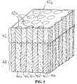
- FIG. 4is an isometric sectional view of the thin film thermal control layer shown in FIG. 3 .
- FIG. 5is an isometric sectional view illustrating a magnetic recording layer deposited on a thin film thermal control layer in accordance with an embodiment of the present invention.
- FIG. 6is a spatial thermal profile in which temperature is plotted versus position along the track of a heat assisted magnetic recording medium including a thin film thermal control layer in accordance with an embodiment of the present invention.
- FIG. 7is a temporal thermal profile in which temperature is plotted versus time for a heat assisted magnetic recording medium including a thin film thermal control layer in accordance with an embodiment of the present invention.
- the present inventionprovides patterned thin films which include regions of relatively low thermal conductivity and regions of relatively high thermal conductivity.
- the terms “low thermal conductivity” and “high thermal conductivity”are relative terms which indicate that the thermal conductivity of one material is lower than the thermal conductivity of the other material.
- the low thermal conductivity regionmay possess a thermal conductivity that is at least 10 percent lower than the thermal conductivity of the high thermal conductivity material, typically at least 100 percent.
- the thin filmsmay be used as thermal control in various applications such as magnetic or other types of data recording media.
- the thin film thermal control layeris provided in a heat assisted magnetic recording medium.
- heat assisted magnetic recording mediais primarily described herein, it is to be understood that the thin film thermal control layers of the present invention may be used in other applications that require laterally confined temperature profiles such as laser material processing and optical recording.
- FIG. 1is a pictorial representation of a disc drive 10 including a heat assisted magnetic recording head.
- the disc drive 10includes a housing 12 (with the upper portion removed and the lower portion visible in this view) sized and configured to contain the various components of the disc drive.
- the disc drive 10includes a spindle motor 14 for rotating at least one magnetic storage medium 16 , which may be a perpendicular magnetic recording medium, within the housing.
- At least one arm 18is contained within the housing 12 , with each arm 18 having a first end 20 with a recording head or slider 22 , and a second end 24 pivotally mounted on a shaft by a bearing 26 .
- An actuator motor 28is located at the arm's second end 24 for pivoting the arm 18 to position the recording head 22 over a desired sector or track 27 of the disc 16 .
- the actuator motor 28is regulated by a controller, which is not shown in this view and is well known in the art.
- FIG. 2is a partially schematic side view of a HAMR head 22 and a magnetic recording medium 16 which includes a patterned thin film thermal control layer 40 in accordance with an embodiment of the present invention.
- a HAMR head 22and a magnetic recording medium 16 which includes a patterned thin film thermal control layer 40 in accordance with an embodiment of the present invention.
- FIG. 2is a partially schematic side view of a HAMR head 22 and a magnetic recording medium 16 which includes a patterned thin film thermal control layer 40 in accordance with an embodiment of the present invention.
- the HAMR head 22includes a writer section comprising a main write pole 30 and a return or opposing pole 32 that are magnetically coupled by a yoke or pedestal 35 . It will be appreciated that the HAMR head 22 may be constructed with a write pole 30 only and no return pole 32 or yoke 35 . A magnetization coil 33 may surround the yoke or pedestal 35 for energizing the HAMR head 22 .
- the HAMR head 22also may include a read head, not shown, which may be any conventional type read head as is generally known in the art.
- the recording medium 16is positioned adjacent to or under the recording head 22 for movement, for example, in the direction of arrow A.
- the recording head 22also includes structure for HAMR to heat the magnetic recording medium 16 proximate to where the write pole 30 applies the magnetic write field H to the recording medium 16 .
- structure for HAMRmay include, for example, a planar optical waveguide schematically represented by reference number 50 .
- the waveguide 50is in optical communication with a light source 52 .
- the light source 52may be, for example, a laser diode, or other suitable laser light sources for coupling a light beam 54 into the waveguide 50 .
- the light source 52may work in association with an optical fiber and external optics, such as an integrated spherical lens, for collimating the light beam 54 from the optical fiber toward a diffraction grating (not shown).
- a lasermay be mounted on the waveguide 50 and the light beam 54 may be directly coupled into the waveguide 50 without the need for external optical configurations.
- the heat-assisted magnetic recording medium 16includes a patterned thin film thermal control layer 40 of the present invention.
- the recording medium 16also includes a substrate 38 , an optional soft underlayer 39 , a magnetic recording layer 42 and a protective overcoat 43 .
- the substrate 38may be made of any suitable material such as ceramic glass, amorphous glass, aluminum or NiP coated AlMg.
- the soft underlayer 39has a typical thickness of from about 50 to about 1,000 nm, and may be made of any suitable material such as CoFe, FeCoB, FeAlN, FeAlSi, NiFe, CoZrNb or FeTaN.
- the soft underlayer 39may also comprise laminated structures such as (FeCoB/Ta) ⁇ n where n is from 2 to 10, or (FeAlSi/C) ⁇ n where n is from 2 to 10.
- the soft underlayer 39may further comprise exchange biased structures such as Cu/(IrMn/FeCo) ⁇ n where n is from 1 to 5.
- the magnetic recording layer 42has a typical thickness of from about 5 to about 30 nm, and may comprise materials having relatively high anisotropies at ambient temperature, such as FePt, FePtNi, CoCrPt, Co/Pt multilayers, and rare earth/transition metal alloys.
- a seed layermay optionally be provided, e.g., between the soft underlayer 39 and the thermal control layer 40 , or between the patterned thin film 40 and the recording layer 42 .
- the seed layermay have has a typical thickness of from about 1 to about 50 nm and may be used to control properties such as orientation and grain size of the subsequently deposited layers.
- the seed layermay be a face centered cubic material such as Pt which controls the orientation of the subsequently deposited film 42 , may be a material such as Ru or Rh which controls grain size and facilitates epitaxial growth of the subsequently deposited layers, or a combination thereof.
- the seed layermay be made of one or more layers of material such as CoCr, CoCrRu, Ru, Pt, Pd, Rh, Ta, TiC, indium tin oxide (ITO), AlN, TiN or ZnO.
- the thermal properties of the seed layershould be compatible with the thermal properties of the magnetic recording layer and the thermal control layer.
- the protective layer 43may be made of any suitable material such as diamond-like carbon.
- FIG. 3is an expanded view of the magnetic recording medium 16 illustrating details of the patterned thin film thermal control layer 40 .
- FIG. 4is an isometric sectional view of the thin film thermal control layer 40 .
- the thin film 40includes regions or phases of relatively low thermal conductivity material 40 a and regions or phases of relatively high thermal conductivity material 40 b .
- the low thermal conductivity regions 40 amay be provided in the form of cylinders separated by a matrix of the high thermal conductivity material 40 b .
- Each cylindrical region 40 ahas a diameter D typically ranging from about 2 to about 50 nm, for example, from about 10 to about 25 nm.
- the spacing S between adjacent thermal insulating cylinders 40 atypically ranges from about 2 to about 50 nm, for example, from about 5 to about 25 nm.
- the thickness T of the thermal control layer 40typically ranges from about 20 to about 500 nm, for example, from about 100 to about 200 nm.
- the cylindrical regions 40 amay have any other suitable cross section such as square, rectangular, annular and the like, such as cuboids having side wall lengths of from about 5 to about 50 nm.
- the high thermal conductivity region 40 btypically comprises a continuous matrix surrounding discrete regions of the low thermal conductivity material 40 a .
- the high thermal conductivity region 40 bmay alternatively be provided as a discontinuous matrix, e.g., the high thermal conductivity regions may be provided as concentric annular areas separated by concentric annular regions of low thermal conductivity material.
- the low thermal conductivity regions 40 a shown in FIGS. 3 and 4may comprise any suitable material, such as ceramic, glass, or metals of low thermal diffusivity and the like.
- the regions 40 amay comprise oxides, borides, nitrides, carbides.
- Specific materials of the regions 40 ainclude an oxide selected from SiO 2 , ZrO 2 , NiO, Al 2 O 3 , MgO, Ta 2 O 5 and TiO 2 ; a boride selected from HfB 2 , and TaB 2 ; a nitride selected from ZrN, TiN, AlN, Si 3 N 4 ; and a carbide selected from ZrC, and SiC, a metal selected from Ti, and Sc.
- the low thermal conductivity regions 40 amay typically comprise SiO 2 , NiO or Al 2 O 3 .
- the high thermal conductivity region 40 bmay comprise any suitable material such as metals, metal alloys or semiconductors.
- the region 40 bmay comprise Cu, CuZr, Au, Al, Pt, Cr, Mo, W and/or Si.
- the high thermal conductivity region 40 bmay be made of Cu, CuZr or Au.
- Table 1lists some of the materials options in conjunction with the present invention, listed in order from low thermal conductivity to high thermal conductivity materials. While oxides such as SiO 2 , ZrO 2 and TiO 2 tend to act as efficient thermal barriers, metals such as Cu, Ag, Au and Al or alloys such as CuZr are good choices for the high thermal conductivity or heat sink materials.
- FIG. 5illustrates a patterned thin film thermal control layer 40 similar to that shown in FIG. 4 with a recording layer 42 deposited thereon in accordance with an embodiment of the present invention.
- the recording layer 42includes a bit pattern of recording regions 42 a separated by spacer regions 42 b .
- Typical materials for the recording regions 42 ainclude FePt, FePtNi, CoCrPt, Co/Pt multilayers and/or rare earth/transition metal alloys.
- Suitable materials for the spacer region 42 binclude NiO, SiO 2 , and/or Cr.
- the recording regions 42 aare provided in the form of cylinders substantially aligned with the underlying low thermal conductivity regions 40 a .
- the cylindrical recording regions 42 amay be aligned along individual recording tracks of the recording medium.
- any other suitable alignment or shapemay be used.
- the recording regions 42 amay have square, rectangular or annular cross sections.
- the thin film thermal control layercomprises a pattern of pillars 40 a made of thermally insulating material embedded in a matrix of a good thermal conductor 40 b .
- a magnetic recording layer 42is deposited on the thermal control layer 40 as shown in FIG. 5 .
- the resulting variation of perpendicular heat transport during HAMR operationsleads to a related variation in the maximum temperature and the vertical temperature gradients notwithstanding whether the magnetic recording layer is granular or continuous.
- a large temperature riseoccurs above the pillars 40 a , and a small increase occurs above the interspaces 40 b .
- the bit pattern of the recording layer 42may be predefined by the pattern of the heat sink regions, and the heating power may be adjusted such that the maximum temperature rise in the magnetic layer on top of the good conducting interspaces/poor conducting pillars is well below or well above the writing temperature.
- the fact that the lateral temperature modulation is mainly governed by the heat sink patternrelaxes the high demands on the lateral confinement of the heat source.
- the thermal control layers of the present inventionmay be made by any suitable processing technique, such as conventional lithography, diblock copolymer lithography, electrodeposition of metals into porous zeolite films, reative ion etching using block copolymer templates, replication and the like.
- One methodis to physically pattern the heat sink layer using conventional lithography. Resist patterning followed by reactive ion etching creates channels, which are then backfilled with a highly conducting metal, such as Cu, Ag, Au or Al, followed by planarization.
- a highly conducting metalsuch as Cu, Ag, Au or Al
- planarizationthe limits of lithographic resolution may restrict this approach, e.g., resolutions of approximately 20 nm may be achieved using electron beam lithography and PMMA resist material.
- diblock copolymersmay be used to achieve the desired lithographic resolution.
- a PMMA/polystyrene diblock copolymermay be used.
- the processinvolves lithographic formation of a self-assembled diblock copolymer film, UV exposure, and removal of one of the block materials.
- the cylinder phasemay be removed and backfilled with a more rigid nonconductive material.
- the surrounding matrix phasemay be removed and a good thermally conductive material may be electrodeposited in the removed region, followed by removing and filling in the cylinder regions with a low thermal conductivity material.
- the final structureis then planarized, e.g., with CMP.
- the diameters of the columnsmay be as small as 10 or 5 nm.
- An alternative route to active patterning and etchingis to use nanoporous or mesoporous materials, such as zeolites, in which the holes/channels are backfilled with a highly conducting metal.
- Metallic nanowiresmay be formed in the oriented zeolite films. Examples of suitable zeolite materials are listed in Table 2. Block co-polymers may be used as templates for reactive ion etching to form metallic nanowires. Porous b-oriented MFI films may also be used in conjunction with the present invention.
- results of numerical simulations on the expected spatial and temporal temperature variationsare shown in FIGS. 6 and 7 respectively.
- the resultsare obtained by a finite-difference-time-domain code using 2 nm and ifs spatial and temporal steps and the following input parameters.
- the magnetic recording layeris 10 nm thick, has a heat capacity of 3.73e6 J/m 3 K, and a vertical thermal conductivity of 99.2 W/mK.
- the lateral thermal conductivity of this layeris set a hundred times smaller to 0.992 W/mK in order to account for the granular nature of this layer.
- the thickness of the thermal control layeris 100 nm.
- the high conductivity matrix of the thermal control layeris assumed to be gold and its heat capacity and thermal conductivity are set to 2.49e6 J/m 3 K and 317 W/mK, respectively.
- the poorly conducting parts of the heat sinkare assumed to be cuboids with dimensions 16 ⁇ 32 nm along and across the track direction, respectively. Whereas the heat capacity of these parts is set identically to the value of gold, their thermal conductivity is set to 0.992 W/mK, i.e., as low as the lateral heat conductivity in the magnetic recording layer. No other layer is considered in the calculations, and it is assumed that there is neither any heat transport from the magnetic recording layer to the air, nor from the thermal control layer to the substrate.
- FIG. 6is a spatial profile in the on-track direction of the surface temperature for various times in increments of 50 ps. These profiles demonstrate the dependence of the maximum temperature on the heat sink pattern comprising relatively high thermal conductivity regions 40 b and relatively low thermal conductivity regions 40 a.
- FIG. 7illustrates the variation of temperature for various cross track positions at the surface and various depths below the center of a heat source versus time, demonstrating that the heat sink pattern not only governs the maximum temperature at the surface but also the vertical temperature gradient.
Landscapes
- Engineering & Computer Science (AREA)
- Chemical & Material Sciences (AREA)
- Nanotechnology (AREA)
- Physics & Mathematics (AREA)
- Mathematical Physics (AREA)
- Theoretical Computer Science (AREA)
- Crystallography & Structural Chemistry (AREA)
- Magnetic Record Carriers (AREA)
- Recording Or Reproducing By Magnetic Means (AREA)
- Chemical Vapour Deposition (AREA)
- Manufacturing Of Magnetic Record Carriers (AREA)
Abstract
Description
| TABLE 1 |
| Thermal Conductivity (cal/sec/K/cm) of |
| Material |
| 20° C. | 100° C. | 400° C. | |
| Fused silica (SiO2) | 0.004 | 0.004 | 0.0048 | ||
| Stabilized ZrO2 | 0.0045 | 0.0047 | 0.005 | ||
| (e.g. YSZ) | |||||
| TiO2 | 0.015 | 0.01 | |||
| HfB2 | 0.015 | ||||
| TaB2 | 0.026 | ||||
| ZrN | .025 | ||||
| (@425° C.) | |||||
| Ta | 0.036 | ||||
| Ti | 0.0411 | ||||
| ZrC | 0.049 | ||||
| NiO | 0.05 | 0.015 | |||
| Ru | 0.057 | ||||
| TiN | 0.069 | ||||
| AlN | 0.072 | 0.053 | |||
| Si3N4 | 0.072 | ||||
| Al2O3 | 0.08 | 0.072 | 0.035 | ||
| MgO | 0.097 | 0.08 | 0.04 | ||
| Cr | 0.16 | ||||
| Co | 0.165 | ||||
| Pt | 0.17 | ||||
| Al | 0.503 | ||||
| Au | 0.71 | ||||
| Cu | 0.934 | ||||
| TABLE 2 |
| Zeolite Materials |
| Pore | ||||
| Zeolite | Ring Size | Pore Size (Å) | Dimension | |
| VFI | ||||
| 18 | 12.7 × 12.7 | [Al18P18O72] | 1 | |
| 14 | 7.2 × 7.5 | [Si32O64] | 1 | |
| 14 | 7.9 × 8.7 | [Al36P36O144] | 1 | |
| 12 | 6.2 × 7.2 | [Si32O64] | 1 | |
| 12 | 7.3 × 7.3 | [Al12P12O48] | 1 | |
| STF | 10 | 5.4 × 5.7 | [Si16O32] | 1 |
| MFI | 10 | 5.3 × 5.6 | [Si96O192] | 3 |
Claims (21)
Priority Applications (3)
| Application Number | Priority Date | Filing Date | Title |
|---|---|---|---|
| US11/033,936US7521137B2 (en) | 2005-01-12 | 2005-01-12 | Patterned thin films and use of such films as thermal control layers in heat assisted magnetic recording media |
| JP2005378275AJP4206406B2 (en) | 2005-01-12 | 2005-12-28 | Patterned thin film, data recording medium and heat-assisted magnetic recording system using the film, and method of manufacturing the thin film |
| KR1020050135209AKR100826032B1 (en) | 2005-01-12 | 2005-12-30 | Patterned thin films and use of such films as thermal control layers in heat assisted magnetic recording media |
Applications Claiming Priority (1)
| Application Number | Priority Date | Filing Date | Title |
|---|---|---|---|
| US11/033,936US7521137B2 (en) | 2005-01-12 | 2005-01-12 | Patterned thin films and use of such films as thermal control layers in heat assisted magnetic recording media |
Publications (2)
| Publication Number | Publication Date |
|---|---|
| US20060154110A1 US20060154110A1 (en) | 2006-07-13 |
| US7521137B2true US7521137B2 (en) | 2009-04-21 |
Family
ID=36653613
Family Applications (1)
| Application Number | Title | Priority Date | Filing Date |
|---|---|---|---|
| US11/033,936Active2026-03-05US7521137B2 (en) | 2005-01-12 | 2005-01-12 | Patterned thin films and use of such films as thermal control layers in heat assisted magnetic recording media |
Country Status (3)
| Country | Link |
|---|---|
| US (1) | US7521137B2 (en) |
| JP (1) | JP4206406B2 (en) |
| KR (1) | KR100826032B1 (en) |
Cited By (22)
| Publication number | Priority date | Publication date | Assignee | Title |
|---|---|---|---|---|
| US20090200359A1 (en)* | 2008-02-13 | 2009-08-13 | Gm Global Technology Operations, Inc. | Reducing sheet distortion in friction stir processing |
| US20100208378A1 (en)* | 2009-02-17 | 2010-08-19 | Seagate Technology Llc | Bit Patterned Media With Embedded Near-Field Transducer |
| US8116171B1 (en) | 2009-11-11 | 2012-02-14 | Western Digital (Fremont), Llc | Method and system for providing energy assisted magnetic recording disk drive using a vertical surface emitting laser |
| US20120207003A1 (en)* | 2011-02-15 | 2012-08-16 | Showa Denko K.K. | Heat-assisted magnetic recording medium and magnetic storage device |
| US8279739B2 (en) | 2009-08-20 | 2012-10-02 | Showa Denko K.K. | Heat-assisted magnetic recording medium and magnetic storage device |
| US8422342B1 (en) | 2010-06-25 | 2013-04-16 | Western Digital (Fremont), Llc | Energy assisted magnetic recording disk drive using a distributed feedback laser |
| US8441896B2 (en) | 2010-06-25 | 2013-05-14 | Western Digital (Fremont), Llc | Energy assisted magnetic recording head having laser integrated mounted to slider |
| US8507114B2 (en)* | 2011-06-30 | 2013-08-13 | Seagate Technology Llc | Recording layer for heat assisted magnetic recording |
| US8582416B2 (en)* | 2012-01-31 | 2013-11-12 | Showa Denko K.K. | Heat-assisted magnetic recording medium and magnetic recording and reading apparatus |
| US20140377143A1 (en)* | 2013-06-20 | 2014-12-25 | Seagate Technology Llc | Filter element for disc drive enclosure |
| US20150138938A1 (en)* | 2013-11-19 | 2015-05-21 | Kabushiki Kaisha Toshiba | Magnetic recording medium, method of manufacturing the same, and magnetic recording device |
| US9177585B1 (en) | 2013-10-23 | 2015-11-03 | WD Media, LLC | Magnetic media capable of improving magnetic properties and thermal management for heat-assisted magnetic recording |
| US9672855B2 (en) | 2012-12-06 | 2017-06-06 | Fuji Electric Co., Ltd. | Perpendicular magnetic recording medium |
| US9822441B2 (en) | 2015-03-31 | 2017-11-21 | WD Media, LLC | Iridium underlayer for heat assisted magnetic recording media |
| US9984713B1 (en) | 2017-06-06 | 2018-05-29 | Seagate Technology Llc | Heat assisted magnetic recording media with enhanced tuning exchange coupling |
| US9984709B1 (en) | 2017-03-22 | 2018-05-29 | Seagate Technology Llc | Heat assisted magnetic recording (HAMR) media with thermal exchange control layer of lower curie temperature |
| US20180211688A1 (en)* | 2017-01-24 | 2018-07-26 | Showa Denko K.K. | Magnetic recording medium and magnetic storage apparatus |
| US10127939B2 (en) | 2017-02-21 | 2018-11-13 | Showa Denko K.K. | Magnetic storage apparatus including a magnetic recording medium having a barrier layer between two heat sink layers |
| US10269381B1 (en) | 2017-10-25 | 2019-04-23 | Seagate Technology Llc | Heat assisted magnetic recording with exchange coupling control layer |
| US10699737B2 (en)* | 2017-02-07 | 2020-06-30 | Showa Denko K.K. | Magnetic recording medium and magnetic storage apparatus |
| US10706884B2 (en) | 2017-01-13 | 2020-07-07 | Showa Denko K.K. | Magnetic recording medium and magnetic storage apparatus |
| US10916262B1 (en) | 2019-12-23 | 2021-02-09 | Seagate Technology Llc | Near field transducers including copper based alloys |
Families Citing this family (34)
| Publication number | Priority date | Publication date | Assignee | Title |
|---|---|---|---|---|
| US7521137B2 (en)* | 2005-01-12 | 2009-04-21 | Seagate Technology Llc | Patterned thin films and use of such films as thermal control layers in heat assisted magnetic recording media |
| US7862914B2 (en)* | 2005-07-26 | 2011-01-04 | Seagate Technology Llc | Heatsink films for magnetic recording media |
| CN100555418C (en)* | 2006-01-24 | 2009-10-28 | 鸿富锦精密工业(深圳)有限公司 | Perpendicular magnetic recording medium and manufacture method thereof |
| US20080026255A1 (en)* | 2006-07-28 | 2008-01-31 | Heraeus, Inc. | Alloy and architecture design for heat-assisted magnetic recording |
| US8900655B2 (en)* | 2006-10-04 | 2014-12-02 | Seagate Technology Llc | Method for fabricating patterned magnetic recording device |
| WO2008056467A1 (en)* | 2006-11-09 | 2008-05-15 | Sharp Kabushiki Kaisha | Magnetic recording medium, magnetic recording/reproduction apparatus and method of magnetic recording/reproduction |
| US8222087B2 (en)* | 2006-12-19 | 2012-07-17 | HGST Netherlands, B.V. | Seed layer for a heat spreader in a magnetic recording head |
| US7755861B1 (en) | 2007-12-06 | 2010-07-13 | Western Digital (Fremont), Llc | Method and system for providing a magnetic recording media |
| KR101496171B1 (en)* | 2007-12-14 | 2015-02-27 | 시게이트 테크놀로지 엘엘씨 | Magnetic thin film structure, magnetic recording media and method of manufacturing the magnetic recording media |
| US8259411B2 (en)* | 2008-05-07 | 2012-09-04 | Seagate Technology Llc | Fabrication of trapezoidal pole for magnetic recording |
| US7965464B2 (en)* | 2008-11-20 | 2011-06-21 | Seagate Technology Llc | Heat-assisted magnetic recording with shaped magnetic and thermal fields |
| JP5479720B2 (en)* | 2008-12-03 | 2014-04-23 | エイチジーエスティーネザーランドビーブイ | Thermally assisted magnetic recording medium |
| US8264788B2 (en)* | 2009-02-23 | 2012-09-11 | Seagate Technology Llc | Discrete track media (DTM) design and fabrication for heat assisted magnetic recording (HAMR) |
| WO2010109822A1 (en)* | 2009-03-23 | 2010-09-30 | 昭和電工株式会社 | Thermally assisted magnetic recording medium, and magnetic recording/reproducing device |
| JP5269693B2 (en)* | 2009-05-12 | 2013-08-21 | 昭和電工株式会社 | Magnetic recording medium |
| US8247095B2 (en)* | 2009-08-21 | 2012-08-21 | Western Digital Technologies, Inc. | Energy assisted discrete track media with heat sink |
| US8795859B2 (en)* | 2010-06-24 | 2014-08-05 | Hoya Corporation | Magnetic recording medium |
| JP2012038884A (en)* | 2010-08-06 | 2012-02-23 | Sony Corp | Magnetic memory element and method for manufacturing magnetic memory element |
| JP5346348B2 (en)* | 2011-02-23 | 2013-11-20 | 株式会社日立製作所 | Magnetic recording medium and magnetic recording apparatus |
| JP5943340B2 (en)* | 2011-03-18 | 2016-07-05 | セイコーインスツル株式会社 | Magnetic recording medium |
| JP5112534B2 (en) | 2011-04-26 | 2013-01-09 | 株式会社東芝 | Magnetic recording medium, manufacturing method thereof, and magnetic recording / reproducing apparatus |
| US9076476B2 (en) | 2011-09-23 | 2015-07-07 | Carnegie Mellon University | Thin film media structure for perpendicular magnetic recording and storage devices made therewith |
| US8605555B1 (en)* | 2012-04-19 | 2013-12-10 | WD Media, LLC | Recording media with multiple bi-layers of heatsink layer and amorphous layer for energy assisted magnetic recording system and methods for fabricating the same |
| US8841007B2 (en)* | 2012-04-27 | 2014-09-23 | Seagate Technology Llc | Data media with tuned thermal conductivity and magnetic permeability |
| SG11201502412YA (en)* | 2012-09-27 | 2015-05-28 | Seagate Technology Llc | Magnetic stack including tin-x intermediate layer |
| JP2014086103A (en)* | 2012-10-23 | 2014-05-12 | Hitachi Ltd | Magnetic recording medium and magnetic storage device |
| US9034492B1 (en)* | 2013-01-11 | 2015-05-19 | WD Media, LLC | Systems and methods for controlling damping of magnetic media for heat assisted magnetic recording |
| US10115428B1 (en) | 2013-02-15 | 2018-10-30 | Wd Media, Inc. | HAMR media structure having an anisotropic thermal barrier layer |
| US8947987B1 (en) | 2013-05-03 | 2015-02-03 | WD Media, LLC | Systems and methods for providing capping layers for heat assisted magnetic recording media |
| US8988976B2 (en)* | 2013-07-09 | 2015-03-24 | Seagate Technology Llc | Composite magnetic recording structure for heat assisted magnetic recording device |
| US9443545B2 (en) | 2013-12-24 | 2016-09-13 | HGST Netherlands B.V. | Thermally stable Au alloys as a heat diffusion and plasmonic underlayer for heat-assisted magnetic recording (HAMR) media |
| US9697859B1 (en)* | 2016-04-01 | 2017-07-04 | WD Media, LLC | Heat-assisted magnetic recording (HAMR) medium including a bi-layer that enables use of lower laser current in write operations |
| JP7538663B2 (en) | 2020-09-03 | 2024-08-22 | Jx金属株式会社 | Sputtering target, manufacturing method thereof, and manufacturing method of magnetic recording medium |
| US11763845B2 (en)* | 2021-12-08 | 2023-09-19 | Seagate Technology Llc | Magnetic stack including non-magnetic seed layer for hard disk drive media |
Citations (34)
| Publication number | Priority date | Publication date | Assignee | Title |
|---|---|---|---|---|
| US4274935A (en) | 1977-07-16 | 1981-06-23 | U.S. Philips Corporation | Magnetic memory layer |
| EP0356201A2 (en) | 1988-08-22 | 1990-02-28 | Sharp Kabushiki Kaisha | Optical recording element and driving system |
| US4935278A (en) | 1988-04-28 | 1990-06-19 | International Business Machines Corporation | Thin film magnetic recording disk and fabrication process |
| US5353268A (en) | 1990-08-10 | 1994-10-04 | Minnesota Mining And Manufacturing Company | Thermomagnetic recording system employing a medium having high storage density and direct-overwrite capability as a result of along-track isocoercivity |
| US5399372A (en) | 1993-11-08 | 1995-03-21 | Southwall Technologies, Inc. | Method of patterning magnetic members |
| US5587223A (en) | 1992-10-19 | 1996-12-24 | Board Of Trustees Leland Stanford, Jr. University | High density magnetic information storage medium |
| US5820769A (en) | 1995-05-24 | 1998-10-13 | Regents Of The University Of Minnesota | Method for making magnetic storage having discrete elements with quantized magnetic moments |
| US5981017A (en) | 1997-12-19 | 1999-11-09 | Western Digital Corporation | Magnetic disk having a heat sink layer above the substrate and method of making |
| US6162532A (en) | 1998-07-31 | 2000-12-19 | International Business Machines Corporation | Magnetic storage medium formed of nanoparticles |
| US6194048B1 (en) | 1997-07-25 | 2001-02-27 | Ebara Corporation | Magnetic recording disk |
| US20010006436A1 (en) | 1999-12-28 | 2001-07-05 | Kabushiki Kaisha Toshiba | Thermally-assisted magnetic recording method and thermally-assisted magnetic recorder |
| US20010006744A1 (en) | 1999-12-20 | 2001-07-05 | Akira Saito | Magnetic recording medium |
| US20010016271A1 (en) | 2000-01-21 | 2001-08-23 | Tdk Corporation | Magnetic recording medium and magnetic write/read method |
| US20010017820A1 (en) | 2000-01-31 | 2001-08-30 | Kabushiki Kaisha Toshiba | Thermally-assisted magnetic recording head, method of manufacturing the same, and thermally-assisted magnetic recording apparatus |
| US20020022198A1 (en) | 1991-12-17 | 2002-02-21 | Ronny Bar-Gadda | Disk medium |
| US20020034666A1 (en) | 2000-09-07 | 2002-03-21 | Kiely James Dillon | Magnetic recording medium utilizing patterned nanoparticle arrays |
| US6367924B1 (en) | 1999-01-11 | 2002-04-09 | Sharp Kabushiki Kaisha | Thermally assisted magnetic recording medium |
| US6392832B1 (en) | 1997-03-26 | 2002-05-21 | Fujitsu Limited | Method for using heat to record on magnetic medium and disk apparatus having temperature changing device |
| US20020086185A1 (en) | 2000-09-29 | 2002-07-04 | Nobuhiro Yasui | Magnetic recording medium and production method thereof |
| US20020136927A1 (en) | 2001-03-22 | 2002-09-26 | Hiroyuki Hieda | Recording medium, method of manufacturing recording medium and recording apparatus |
| US20020168548A1 (en) | 2001-05-09 | 2002-11-14 | Masatoshi Sakurai | Recording medium, method of manufacturing recording medium and recording-reproducing apparatus |
| US6579590B2 (en) | 2001-11-16 | 2003-06-17 | Hitachi Global Storage Technologies Netherlands B.V. | Thermally-assisted magnetic recording disk with multilayered thermal barrier |
| US6603619B1 (en) | 1999-01-07 | 2003-08-05 | Sharp Kabushiki Kaisha | Magnetic storage medium and heat assisted recording and reproduction method |
| US6703099B2 (en) | 2000-07-27 | 2004-03-09 | Seagate Technology Llc | Perpendicular magnetic recording media with patterned soft magnetic underlayer |
| US20040062503A1 (en)* | 2002-09-30 | 2004-04-01 | Seagate Technology Llc | Planar waveguide for heat assisted magnetic recording |
| US6754020B1 (en)* | 1999-09-02 | 2004-06-22 | Kabushiki Kaisha Toshiba | Magnetic recording media and magnetic recording/reproduction apparatuses |
| US6775100B1 (en) | 1997-05-05 | 2004-08-10 | Seagate Technology Llc | Laser assisted track width definition and radial control with magnetic recording |
| US20040240327A1 (en)* | 2003-05-29 | 2004-12-02 | Seagate Technology Llc | Patterned media for heat assisted magnetic recording |
| US20050041950A1 (en)* | 2002-06-28 | 2005-02-24 | Seagate Technology Llc | Heat assisted magnetic recording with heat profile shaping |
| US20050193405A1 (en)* | 2004-02-27 | 2005-09-01 | Tdk Corporation | Magnetic recording and reproducing device and magnetic recording medium |
| US6944101B2 (en)* | 2002-06-24 | 2005-09-13 | Seagate Technology Llc | Recording pole for delivering coincident heat and magnetic field |
| US20060154110A1 (en)* | 2005-01-12 | 2006-07-13 | Seagate Technology Llc | Patterned thin films and use of such films as thermal control layers in heat assisted magnetic recording media |
| US7158346B2 (en)* | 2003-12-23 | 2007-01-02 | Seagate Technology Llc | Heat assisted magnetic recording film including superparamagnetic nanoparticles dispersed in an antiferromagnetic or ferrimagnetic matrix |
| US20070036040A1 (en)* | 2005-08-11 | 2007-02-15 | Seagate Technology Llc | Dual wire integrated WAMR/HAMR writing head |
Family Cites Families (5)
| Publication number | Priority date | Publication date | Assignee | Title |
|---|---|---|---|---|
| JPH05342655A (en)* | 1992-06-12 | 1993-12-24 | Hitachi Ltd | Magneto-optical recording medium |
| JP2000195034A (en)* | 1998-12-25 | 2000-07-14 | Toshiba Corp | Magnetic recording medium and manufacturing method thereof |
| JP2001319314A (en)* | 2000-02-29 | 2001-11-16 | Hitachi Ltd | Magnetic recording medium, method of manufacturing the same, and magnetic recording apparatus using the same |
| JP2002074647A (en) | 2000-08-25 | 2002-03-15 | Hitachi Maxell Ltd | Magnetic recording medium and magnetic recording device using the same |
| KR100571812B1 (en)* | 2003-07-19 | 2006-04-17 | 삼성전자주식회사 | Patterned magnetic recording medium and manufacturing method thereof |
- 2005
- 2005-01-12USUS11/033,936patent/US7521137B2/enactiveActive
- 2005-12-28JPJP2005378275Apatent/JP4206406B2/ennot_activeExpired - Fee Related
- 2005-12-30KRKR1020050135209Apatent/KR100826032B1/ennot_activeExpired - Fee Related
Patent Citations (40)
| Publication number | Priority date | Publication date | Assignee | Title |
|---|---|---|---|---|
| US4274935A (en) | 1977-07-16 | 1981-06-23 | U.S. Philips Corporation | Magnetic memory layer |
| US4935278A (en) | 1988-04-28 | 1990-06-19 | International Business Machines Corporation | Thin film magnetic recording disk and fabrication process |
| EP0356201A2 (en) | 1988-08-22 | 1990-02-28 | Sharp Kabushiki Kaisha | Optical recording element and driving system |
| US5353268A (en) | 1990-08-10 | 1994-10-04 | Minnesota Mining And Manufacturing Company | Thermomagnetic recording system employing a medium having high storage density and direct-overwrite capability as a result of along-track isocoercivity |
| US20020022198A1 (en) | 1991-12-17 | 2002-02-21 | Ronny Bar-Gadda | Disk medium |
| US5587223A (en) | 1992-10-19 | 1996-12-24 | Board Of Trustees Leland Stanford, Jr. University | High density magnetic information storage medium |
| US5399372A (en) | 1993-11-08 | 1995-03-21 | Southwall Technologies, Inc. | Method of patterning magnetic members |
| US5820769A (en) | 1995-05-24 | 1998-10-13 | Regents Of The University Of Minnesota | Method for making magnetic storage having discrete elements with quantized magnetic moments |
| US5956216A (en) | 1995-05-24 | 1999-09-21 | Regents Of The University Of Minnesota | Magnetic storage having discrete elements with quantized magnetic moments |
| US6392832B1 (en) | 1997-03-26 | 2002-05-21 | Fujitsu Limited | Method for using heat to record on magnetic medium and disk apparatus having temperature changing device |
| US6775100B1 (en) | 1997-05-05 | 2004-08-10 | Seagate Technology Llc | Laser assisted track width definition and radial control with magnetic recording |
| US6194048B1 (en) | 1997-07-25 | 2001-02-27 | Ebara Corporation | Magnetic recording disk |
| US5981017A (en) | 1997-12-19 | 1999-11-09 | Western Digital Corporation | Magnetic disk having a heat sink layer above the substrate and method of making |
| US6162532A (en) | 1998-07-31 | 2000-12-19 | International Business Machines Corporation | Magnetic storage medium formed of nanoparticles |
| US6603619B1 (en) | 1999-01-07 | 2003-08-05 | Sharp Kabushiki Kaisha | Magnetic storage medium and heat assisted recording and reproduction method |
| US6367924B1 (en) | 1999-01-11 | 2002-04-09 | Sharp Kabushiki Kaisha | Thermally assisted magnetic recording medium |
| US6754020B1 (en)* | 1999-09-02 | 2004-06-22 | Kabushiki Kaisha Toshiba | Magnetic recording media and magnetic recording/reproduction apparatuses |
| US20010006744A1 (en) | 1999-12-20 | 2001-07-05 | Akira Saito | Magnetic recording medium |
| US6579634B2 (en) | 1999-12-20 | 2003-06-17 | Fuji Electric Co., Ltd. | Magnetic recording medium |
| US20010006436A1 (en) | 1999-12-28 | 2001-07-05 | Kabushiki Kaisha Toshiba | Thermally-assisted magnetic recording method and thermally-assisted magnetic recorder |
| US6636460B2 (en) | 1999-12-28 | 2003-10-21 | Kabushiki Kaisha Toshiba | Thermally-assisted magnetic recording method and thermally-assisted magnetic recorder |
| US20010016271A1 (en) | 2000-01-21 | 2001-08-23 | Tdk Corporation | Magnetic recording medium and magnetic write/read method |
| US6620532B2 (en) | 2000-01-21 | 2003-09-16 | Tdk Corporation | Magnetic recording medium and magnetic write/read method |
| US20010017820A1 (en) | 2000-01-31 | 2001-08-30 | Kabushiki Kaisha Toshiba | Thermally-assisted magnetic recording head, method of manufacturing the same, and thermally-assisted magnetic recording apparatus |
| US6703099B2 (en) | 2000-07-27 | 2004-03-09 | Seagate Technology Llc | Perpendicular magnetic recording media with patterned soft magnetic underlayer |
| US20020034666A1 (en) | 2000-09-07 | 2002-03-21 | Kiely James Dillon | Magnetic recording medium utilizing patterned nanoparticle arrays |
| US20020086185A1 (en) | 2000-09-29 | 2002-07-04 | Nobuhiro Yasui | Magnetic recording medium and production method thereof |
| US6858319B2 (en) | 2000-09-29 | 2005-02-22 | Canon Kabushiki Kaisha | Magnetic recording medium including aluminum layer having holes and production method thereof |
| US20020136927A1 (en) | 2001-03-22 | 2002-09-26 | Hiroyuki Hieda | Recording medium, method of manufacturing recording medium and recording apparatus |
| US20020168548A1 (en) | 2001-05-09 | 2002-11-14 | Masatoshi Sakurai | Recording medium, method of manufacturing recording medium and recording-reproducing apparatus |
| US6579590B2 (en) | 2001-11-16 | 2003-06-17 | Hitachi Global Storage Technologies Netherlands B.V. | Thermally-assisted magnetic recording disk with multilayered thermal barrier |
| US6944101B2 (en)* | 2002-06-24 | 2005-09-13 | Seagate Technology Llc | Recording pole for delivering coincident heat and magnetic field |
| US20050041950A1 (en)* | 2002-06-28 | 2005-02-24 | Seagate Technology Llc | Heat assisted magnetic recording with heat profile shaping |
| US20040062503A1 (en)* | 2002-09-30 | 2004-04-01 | Seagate Technology Llc | Planar waveguide for heat assisted magnetic recording |
| US7027700B2 (en)* | 2002-09-30 | 2006-04-11 | Seagate Technology Llc | Planar waveguide for heat assisted magnetic recording |
| US20040240327A1 (en)* | 2003-05-29 | 2004-12-02 | Seagate Technology Llc | Patterned media for heat assisted magnetic recording |
| US7158346B2 (en)* | 2003-12-23 | 2007-01-02 | Seagate Technology Llc | Heat assisted magnetic recording film including superparamagnetic nanoparticles dispersed in an antiferromagnetic or ferrimagnetic matrix |
| US20050193405A1 (en)* | 2004-02-27 | 2005-09-01 | Tdk Corporation | Magnetic recording and reproducing device and magnetic recording medium |
| US20060154110A1 (en)* | 2005-01-12 | 2006-07-13 | Seagate Technology Llc | Patterned thin films and use of such films as thermal control layers in heat assisted magnetic recording media |
| US20070036040A1 (en)* | 2005-08-11 | 2007-02-15 | Seagate Technology Llc | Dual wire integrated WAMR/HAMR writing head |
Cited By (28)
| Publication number | Priority date | Publication date | Assignee | Title |
|---|---|---|---|---|
| US20090200359A1 (en)* | 2008-02-13 | 2009-08-13 | Gm Global Technology Operations, Inc. | Reducing sheet distortion in friction stir processing |
| US20100208378A1 (en)* | 2009-02-17 | 2010-08-19 | Seagate Technology Llc | Bit Patterned Media With Embedded Near-Field Transducer |
| US7961417B2 (en)* | 2009-02-17 | 2011-06-14 | Seagate Technology Llc | Heat assisted magnetic recording apparatus having a plurality of near-field transducers in a recording media |
| US8279739B2 (en) | 2009-08-20 | 2012-10-02 | Showa Denko K.K. | Heat-assisted magnetic recording medium and magnetic storage device |
| US8116171B1 (en) | 2009-11-11 | 2012-02-14 | Western Digital (Fremont), Llc | Method and system for providing energy assisted magnetic recording disk drive using a vertical surface emitting laser |
| US8422342B1 (en) | 2010-06-25 | 2013-04-16 | Western Digital (Fremont), Llc | Energy assisted magnetic recording disk drive using a distributed feedback laser |
| US8441896B2 (en) | 2010-06-25 | 2013-05-14 | Western Digital (Fremont), Llc | Energy assisted magnetic recording head having laser integrated mounted to slider |
| US9245543B1 (en) | 2010-06-25 | 2016-01-26 | Western Digital (Fremont), Llc | Method for providing an energy assisted magnetic recording head having a laser integrally mounted to the slider |
| US20120207003A1 (en)* | 2011-02-15 | 2012-08-16 | Showa Denko K.K. | Heat-assisted magnetic recording medium and magnetic storage device |
| US8542569B2 (en)* | 2011-02-15 | 2013-09-24 | Showa Denko K.K. | Heat-assisted magnetic recording medium and magnetic storage device |
| US8507114B2 (en)* | 2011-06-30 | 2013-08-13 | Seagate Technology Llc | Recording layer for heat assisted magnetic recording |
| US9443544B1 (en) | 2011-06-30 | 2016-09-13 | Seagate Technology Llc | Recording layer for heat assisted magnetic recording |
| US8582416B2 (en)* | 2012-01-31 | 2013-11-12 | Showa Denko K.K. | Heat-assisted magnetic recording medium and magnetic recording and reading apparatus |
| US9672855B2 (en) | 2012-12-06 | 2017-06-06 | Fuji Electric Co., Ltd. | Perpendicular magnetic recording medium |
| US9230608B2 (en)* | 2013-06-20 | 2016-01-05 | Seagate Technology Llc | Filter element for disc drive enclosure |
| US20140377143A1 (en)* | 2013-06-20 | 2014-12-25 | Seagate Technology Llc | Filter element for disc drive enclosure |
| US9177585B1 (en) | 2013-10-23 | 2015-11-03 | WD Media, LLC | Magnetic media capable of improving magnetic properties and thermal management for heat-assisted magnetic recording |
| US20150138938A1 (en)* | 2013-11-19 | 2015-05-21 | Kabushiki Kaisha Toshiba | Magnetic recording medium, method of manufacturing the same, and magnetic recording device |
| US9822441B2 (en) | 2015-03-31 | 2017-11-21 | WD Media, LLC | Iridium underlayer for heat assisted magnetic recording media |
| US10706884B2 (en) | 2017-01-13 | 2020-07-07 | Showa Denko K.K. | Magnetic recording medium and magnetic storage apparatus |
| US20180211688A1 (en)* | 2017-01-24 | 2018-07-26 | Showa Denko K.K. | Magnetic recording medium and magnetic storage apparatus |
| US10803895B2 (en)* | 2017-01-24 | 2020-10-13 | Showa Denko K.K. | Magnetic recording medium and magnetic storage apparatus |
| US10699737B2 (en)* | 2017-02-07 | 2020-06-30 | Showa Denko K.K. | Magnetic recording medium and magnetic storage apparatus |
| US10127939B2 (en) | 2017-02-21 | 2018-11-13 | Showa Denko K.K. | Magnetic storage apparatus including a magnetic recording medium having a barrier layer between two heat sink layers |
| US9984709B1 (en) | 2017-03-22 | 2018-05-29 | Seagate Technology Llc | Heat assisted magnetic recording (HAMR) media with thermal exchange control layer of lower curie temperature |
| US9984713B1 (en) | 2017-06-06 | 2018-05-29 | Seagate Technology Llc | Heat assisted magnetic recording media with enhanced tuning exchange coupling |
| US10269381B1 (en) | 2017-10-25 | 2019-04-23 | Seagate Technology Llc | Heat assisted magnetic recording with exchange coupling control layer |
| US10916262B1 (en) | 2019-12-23 | 2021-02-09 | Seagate Technology Llc | Near field transducers including copper based alloys |
Also Published As
| Publication number | Publication date |
|---|---|
| US20060154110A1 (en) | 2006-07-13 |
| JP4206406B2 (en) | 2009-01-14 |
| KR100826032B1 (en) | 2008-04-28 |
| KR20060082396A (en) | 2006-07-18 |
| JP2006196151A (en) | 2006-07-27 |
Similar Documents
| Publication | Publication Date | Title |
|---|---|---|
| US7521137B2 (en) | Patterned thin films and use of such films as thermal control layers in heat assisted magnetic recording media | |
| US9001630B1 (en) | Energy assisted magnetic recording medium capable of suppressing high DC readback noise | |
| US8268461B1 (en) | Patterned perpendicular magnetic recording medium with ultrathin oxide film and reduced switching field distribution | |
| US8081542B1 (en) | Thermally-assisted recording (TAR) disk drive with patterned multilevel media and laser with power modulation | |
| US20120147718A1 (en) | PATTERNED PERPENDICULAR MAGNETIC RECORDING MEDIUM WITH EXCHANGE-COUPLED COMPOSITE RECORDING STRUCTURE OF A FePt LAYER AND A Co/X MULTILAYER | |
| JP2011129241A (en) | Perpendicular magnetic recording disk, and method of manufacturing the same | |
| JP4381444B2 (en) | Magnetic recording medium, method for manufacturing magnetic recording medium, and magnetic recording apparatus | |
| US8164988B2 (en) | All-optical magnetic recording system using circularly polarized light and bit-patterned media | |
| US20130084387A1 (en) | METHOD FOR MAKING A PATTERNED PERPENDICULAR MAGNETIC RECORDING DISK HAVING A FePt or CoPt CHEMICALLY ORDERED RECORDING LAYER | |
| JP2005166240A (en) | Method for magnetic recording on patterned multilevel perpendicular media using thermal assist and constant write current | |
| JP2005166239A (en) | Magnetic recording apparatus using patterned multilevel perpendicular magnetic recording. | |
| JP2004118956A (en) | Magnetic recording media | |
| KR100662148B1 (en) | Heat assisted magnetic recording film including superparamagnetic nanoparticles dispersed in an antiferromagnetic or ferrimagnetic matrix | |
| CN101369429A (en) | Perpendicular magnetic recording medium and method | |
| CN101471086B (en) | Patterned magnetic recording media with exchange bridge structure and methods of forming the same | |
| US8320232B1 (en) | Patterned perpendicular magnetic recording medium with multiple magnetic layers and interlayers | |
| US11011203B1 (en) | Patterned thermal absorption layer for granular storage media | |
| US9183865B1 (en) | Patterned perpendicular magnetic recording medium with ultrathin noble metal interlayer | |
| US9147423B2 (en) | Method for improving a patterned perpendicular magnetic recording disk with annealing | |
| CN101855672B (en) | Magnetic storage device, particularly for a hard drive, and method for making same | |
| JP2011258256A (en) | Magnetic recording device | |
| JP3811880B2 (en) | Magnetic recording medium | |
| US8169728B2 (en) | Magnetic medium having an artificial pattern structure using a gradient of a magnetization reversal field and a method of use thereof | |
| US20120082865A1 (en) | Method for forming a magnetic recording medium and a magnetic recording medium formed thereof | |
| Kikitsu et al. | Patterned magnetic recording media |
Legal Events
| Date | Code | Title | Description |
|---|---|---|---|
| AS | Assignment | Owner name:SEAGATE TECHNOLOGY LLC, CALIFORNIA Free format text:ASSIGNMENT OF ASSIGNORS INTEREST;ASSIGNORS:HOHLFELD, JULIUS KURT;KUBOTA, YUKIKO;WELLER, DIETER KLAUS;AND OTHERS;REEL/FRAME:016179/0296;SIGNING DATES FROM 20050103 TO 20050112 | |
| STCF | Information on status: patent grant | Free format text:PATENTED CASE | |
| AS | Assignment | Owner name:WELLS FARGO BANK, NATIONAL ASSOCIATION, AS COLLATERAL AGENT AND SECOND PRIORITY REPRESENTATIVE, CALIFORNIA Free format text:SECURITY AGREEMENT;ASSIGNORS:MAXTOR CORPORATION;SEAGATE TECHNOLOGY LLC;SEAGATE TECHNOLOGY INTERNATIONAL;REEL/FRAME:022757/0017 Effective date:20090507 Owner name:JPMORGAN CHASE BANK, N.A., AS ADMINISTRATIVE AGENT AND FIRST PRIORITY REPRESENTATIVE, NEW YORK Free format text:SECURITY AGREEMENT;ASSIGNORS:MAXTOR CORPORATION;SEAGATE TECHNOLOGY LLC;SEAGATE TECHNOLOGY INTERNATIONAL;REEL/FRAME:022757/0017 Effective date:20090507 Owner name:JPMORGAN CHASE BANK, N.A., AS ADMINISTRATIVE AGENT Free format text:SECURITY AGREEMENT;ASSIGNORS:MAXTOR CORPORATION;SEAGATE TECHNOLOGY LLC;SEAGATE TECHNOLOGY INTERNATIONAL;REEL/FRAME:022757/0017 Effective date:20090507 Owner name:WELLS FARGO BANK, NATIONAL ASSOCIATION, AS COLLATE Free format text:SECURITY AGREEMENT;ASSIGNORS:MAXTOR CORPORATION;SEAGATE TECHNOLOGY LLC;SEAGATE TECHNOLOGY INTERNATIONAL;REEL/FRAME:022757/0017 Effective date:20090507 | |
| CC | Certificate of correction | ||
| AS | Assignment | Owner name:SEAGATE TECHNOLOGY INTERNATIONAL, CALIFORNIA Free format text:RELEASE;ASSIGNOR:JPMORGAN CHASE BANK, N.A., AS ADMINISTRATIVE AGENT;REEL/FRAME:025662/0001 Effective date:20110114 Owner name:SEAGATE TECHNOLOGY LLC, CALIFORNIA Free format text:RELEASE;ASSIGNOR:JPMORGAN CHASE BANK, N.A., AS ADMINISTRATIVE AGENT;REEL/FRAME:025662/0001 Effective date:20110114 Owner name:MAXTOR CORPORATION, CALIFORNIA Free format text:RELEASE;ASSIGNOR:JPMORGAN CHASE BANK, N.A., AS ADMINISTRATIVE AGENT;REEL/FRAME:025662/0001 Effective date:20110114 Owner name:SEAGATE TECHNOLOGY HDD HOLDINGS, CALIFORNIA Free format text:RELEASE;ASSIGNOR:JPMORGAN CHASE BANK, N.A., AS ADMINISTRATIVE AGENT;REEL/FRAME:025662/0001 Effective date:20110114 | |
| AS | Assignment | Owner name:THE BANK OF NOVA SCOTIA, AS ADMINISTRATIVE AGENT, CANADA Free format text:SECURITY AGREEMENT;ASSIGNOR:SEAGATE TECHNOLOGY LLC;REEL/FRAME:026010/0350 Effective date:20110118 Owner name:THE BANK OF NOVA SCOTIA, AS ADMINISTRATIVE AGENT, Free format text:SECURITY AGREEMENT;ASSIGNOR:SEAGATE TECHNOLOGY LLC;REEL/FRAME:026010/0350 Effective date:20110118 | |
| FPAY | Fee payment | Year of fee payment:4 | |
| AS | Assignment | Owner name:SEAGATE TECHNOLOGY US HOLDINGS, INC., CALIFORNIA Free format text:TERMINATION AND RELEASE OF SECURITY INTEREST IN PATENT RIGHTS;ASSIGNOR:WELLS FARGO BANK, NATIONAL ASSOCIATION, AS COLLATERAL AGENT AND SECOND PRIORITY REPRESENTATIVE;REEL/FRAME:030833/0001 Effective date:20130312 Owner name:EVAULT INC. (F/K/A I365 INC.), CALIFORNIA Free format text:TERMINATION AND RELEASE OF SECURITY INTEREST IN PATENT RIGHTS;ASSIGNOR:WELLS FARGO BANK, NATIONAL ASSOCIATION, AS COLLATERAL AGENT AND SECOND PRIORITY REPRESENTATIVE;REEL/FRAME:030833/0001 Effective date:20130312 Owner name:SEAGATE TECHNOLOGY LLC, CALIFORNIA Free format text:TERMINATION AND RELEASE OF SECURITY INTEREST IN PATENT RIGHTS;ASSIGNOR:WELLS FARGO BANK, NATIONAL ASSOCIATION, AS COLLATERAL AGENT AND SECOND PRIORITY REPRESENTATIVE;REEL/FRAME:030833/0001 Effective date:20130312 Owner name:SEAGATE TECHNOLOGY INTERNATIONAL, CAYMAN ISLANDS Free format text:TERMINATION AND RELEASE OF SECURITY INTEREST IN PATENT RIGHTS;ASSIGNOR:WELLS FARGO BANK, NATIONAL ASSOCIATION, AS COLLATERAL AGENT AND SECOND PRIORITY REPRESENTATIVE;REEL/FRAME:030833/0001 Effective date:20130312 | |
| FPAY | Fee payment | Year of fee payment:8 | |
| MAFP | Maintenance fee payment | Free format text:PAYMENT OF MAINTENANCE FEE, 12TH YEAR, LARGE ENTITY (ORIGINAL EVENT CODE: M1553); ENTITY STATUS OF PATENT OWNER: LARGE ENTITY Year of fee payment:12 | |
| AS | Assignment | Owner name:SEAGATE TECHNOLOGY PUBLIC LIMITED COMPANY, CALIFORNIA Free format text:RELEASE BY SECURED PARTY;ASSIGNOR:THE BANK OF NOVA SCOTIA;REEL/FRAME:072193/0001 Effective date:20250303 Owner name:SEAGATE TECHNOLOGY, CALIFORNIA Free format text:RELEASE BY SECURED PARTY;ASSIGNOR:THE BANK OF NOVA SCOTIA;REEL/FRAME:072193/0001 Effective date:20250303 Owner name:SEAGATE TECHNOLOGY HDD HOLDINGS, CALIFORNIA Free format text:RELEASE BY SECURED PARTY;ASSIGNOR:THE BANK OF NOVA SCOTIA;REEL/FRAME:072193/0001 Effective date:20250303 Owner name:I365 INC., CALIFORNIA Free format text:RELEASE BY SECURED PARTY;ASSIGNOR:THE BANK OF NOVA SCOTIA;REEL/FRAME:072193/0001 Effective date:20250303 Owner name:SEAGATE TECHNOLOGY LLC, CALIFORNIA Free format text:RELEASE BY SECURED PARTY;ASSIGNOR:THE BANK OF NOVA SCOTIA;REEL/FRAME:072193/0001 Effective date:20250303 Owner name:SEAGATE TECHNOLOGY INTERNATIONAL, CAYMAN ISLANDS Free format text:RELEASE BY SECURED PARTY;ASSIGNOR:THE BANK OF NOVA SCOTIA;REEL/FRAME:072193/0001 Effective date:20250303 Owner name:SEAGATE HDD CAYMAN, CAYMAN ISLANDS Free format text:RELEASE BY SECURED PARTY;ASSIGNOR:THE BANK OF NOVA SCOTIA;REEL/FRAME:072193/0001 Effective date:20250303 Owner name:SEAGATE TECHNOLOGY (US) HOLDINGS, INC., CALIFORNIA Free format text:RELEASE BY SECURED PARTY;ASSIGNOR:THE BANK OF NOVA SCOTIA;REEL/FRAME:072193/0001 Effective date:20250303 |