US7520893B2 - Method for treating neurovascular aneurysms - Google Patents
Method for treating neurovascular aneurysmsDownload PDFInfo
- Publication number
- US7520893B2 US7520893B2US11/069,613US6961305AUS7520893B2US 7520893 B2US7520893 B2US 7520893B2US 6961305 AUS6961305 AUS 6961305AUS 7520893 B2US7520893 B2US 7520893B2
- Authority
- US
- United States
- Prior art keywords
- stent
- ribbon
- width
- catheter
- openings
- Prior art date
- Legal status (The legal status is an assumption and is not a legal conclusion. Google has not performed a legal analysis and makes no representation as to the accuracy of the status listed.)
- Expired - Fee Related, expires
Links
- 238000000034methodMethods0.000titleclaimsabstractdescription37
- 206010002329AneurysmDiseases0.000titleabstractdescription17
- 238000004804windingMethods0.000claimsabstractdescription36
- 230000007704transitionEffects0.000claimsabstractdescription17
- 238000011144upstream manufacturingMethods0.000claimsdescription33
- 239000000956alloySubstances0.000claimsdescription13
- 229910000734martensiteInorganic materials0.000claimsdescription13
- 229910045601alloyInorganic materials0.000claimsdescription12
- 230000007423decreaseEffects0.000claimsdescription11
- 229910001285shape-memory alloyInorganic materials0.000claimsdescription10
- 230000003902lesionEffects0.000claimsdescription9
- 230000003247decreasing effectEffects0.000claimsdescription6
- 230000002250progressing effectEffects0.000claimsdescription3
- 229910052751metalInorganic materials0.000abstractdescription8
- 239000002184metalSubstances0.000abstractdescription8
- 238000011282treatmentMethods0.000abstractdescription7
- 231100000216vascular lesionToxicity0.000abstractdescription3
- 206010003226Arteriovenous fistulaDiseases0.000abstract1
- 238000004519manufacturing processMethods0.000description9
- 229910001000nickel titaniumInorganic materials0.000description8
- HLXZNVUGXRDIFK-UHFFFAOYSA-Nnickel titaniumChemical compound[Ti].[Ti].[Ti].[Ti].[Ti].[Ti].[Ti].[Ti].[Ti].[Ti].[Ti].[Ni].[Ni].[Ni].[Ni].[Ni].[Ni].[Ni].[Ni].[Ni].[Ni].[Ni].[Ni].[Ni].[Ni]HLXZNVUGXRDIFK-UHFFFAOYSA-N0.000description7
- 238000005452bendingMethods0.000description6
- 230000002792vascularEffects0.000description6
- PXHVJJICTQNCMI-UHFFFAOYSA-NNickelChemical compound[Ni]PXHVJJICTQNCMI-UHFFFAOYSA-N0.000description4
- 230000004087circulationEffects0.000description4
- 239000011800void materialSubstances0.000description4
- 208000007536ThrombosisDiseases0.000description3
- PCHJSUWPFVWCPO-UHFFFAOYSA-NgoldChemical compound[Au]PCHJSUWPFVWCPO-UHFFFAOYSA-N0.000description3
- 239000010931goldSubstances0.000description3
- 229910052737goldInorganic materials0.000description3
- 239000000463materialSubstances0.000description3
- 230000008569processEffects0.000description3
- 206010053567CoagulopathiesDiseases0.000description2
- XEEYBQQBJWHFJM-UHFFFAOYSA-NIronChemical compound[Fe]XEEYBQQBJWHFJM-UHFFFAOYSA-N0.000description2
- 208000032851Subarachnoid HemorrhageDiseases0.000description2
- RTAQQCXQSZGOHL-UHFFFAOYSA-NTitaniumChemical compound[Ti]RTAQQCXQSZGOHL-UHFFFAOYSA-N0.000description2
- 210000001367arteryAnatomy0.000description2
- 230000008901benefitEffects0.000description2
- 230000036760body temperatureEffects0.000description2
- 210000000275circle of willisAnatomy0.000description2
- 230000035602clottingEffects0.000description2
- 230000006378damageEffects0.000description2
- 201000010099diseaseDiseases0.000description2
- 208000037265diseases, disorders, signs and symptomsDiseases0.000description2
- 239000003814drugSubstances0.000description2
- 238000005516engineering processMethods0.000description2
- 238000000227grindingMethods0.000description2
- 230000000004hemodynamic effectEffects0.000description2
- 208000014674injuryDiseases0.000description2
- 238000003698laser cuttingMethods0.000description2
- 238000012986modificationMethods0.000description2
- 230000004048modificationEffects0.000description2
- 229910052759nickelInorganic materials0.000description2
- 230000002829reductive effectEffects0.000description2
- 230000000717retained effectEffects0.000description2
- 239000010936titaniumSubstances0.000description2
- 229910052719titaniumInorganic materials0.000description2
- 229910000619316 stainless steelInorganic materials0.000description1
- VYZAMTAEIAYCRO-UHFFFAOYSA-NChromiumChemical compound[Cr]VYZAMTAEIAYCRO-UHFFFAOYSA-N0.000description1
- 229910000531Co alloyInorganic materials0.000description1
- 206010016717FistulaDiseases0.000description1
- 208000032843HemorrhageDiseases0.000description1
- ZOKXTWBITQBERF-UHFFFAOYSA-NMolybdenumChemical compound[Mo]ZOKXTWBITQBERF-UHFFFAOYSA-N0.000description1
- 229910000831SteelInorganic materials0.000description1
- 208000027418Wounds and injuryDiseases0.000description1
- 230000002411adverseEffects0.000description1
- 239000000560biocompatible materialSubstances0.000description1
- 230000015572biosynthetic processEffects0.000description1
- 239000008280bloodSubstances0.000description1
- 210000004369bloodAnatomy0.000description1
- 230000017531blood circulationEffects0.000description1
- 230000023555blood coagulationEffects0.000description1
- 210000004204blood vesselAnatomy0.000description1
- 210000004556brainAnatomy0.000description1
- 210000004004carotid artery internalAnatomy0.000description1
- 239000013043chemical agentSubstances0.000description1
- 238000003486chemical etchingMethods0.000description1
- 229910052804chromiumInorganic materials0.000description1
- 239000011651chromiumSubstances0.000description1
- 239000011248coating agentSubstances0.000description1
- 238000000576coating methodMethods0.000description1
- 238000010276constructionMethods0.000description1
- 238000001816coolingMethods0.000description1
- 230000003111delayed effectEffects0.000description1
- 229910003460diamondInorganic materials0.000description1
- 239000010432diamondSubstances0.000description1
- 229940079593drugDrugs0.000description1
- 230000000694effectsEffects0.000description1
- 229910000701elgiloys (Co-Cr-Ni Alloy)Inorganic materials0.000description1
- 210000002889endothelial cellAnatomy0.000description1
- 210000001105femoral arteryAnatomy0.000description1
- 230000003890fistulaEffects0.000description1
- 238000002594fluoroscopyMethods0.000description1
- 230000006870functionEffects0.000description1
- 206010020718hyperplasiaDiseases0.000description1
- 238000007917intracranial administrationMethods0.000description1
- 238000010884ion-beam techniqueMethods0.000description1
- 229910052742ironInorganic materials0.000description1
- 230000000670limiting effectEffects0.000description1
- 238000005259measurementMethods0.000description1
- 229910001092metal group alloyInorganic materials0.000description1
- 150000002739metalsChemical class0.000description1
- 238000005555metalworkingMethods0.000description1
- 229910052750molybdenumInorganic materials0.000description1
- 239000011733molybdenumSubstances0.000description1
- 230000008729neurovascular lesionEffects0.000description1
- 230000002093peripheral effectEffects0.000description1
- 238000005498polishingMethods0.000description1
- 229920000642polymerPolymers0.000description1
- 210000003137popliteal arteryAnatomy0.000description1
- 210000002254renal arteryAnatomy0.000description1
- 230000004044responseEffects0.000description1
- 238000012216screeningMethods0.000description1
- 239000010959steelSubstances0.000description1
- 238000011477surgical interventionMethods0.000description1
- 230000001225therapeutic effectEffects0.000description1
- 230000009466transformationEffects0.000description1
- 230000008733traumaEffects0.000description1
- 238000010792warmingMethods0.000description1
Images


Classifications
- A—HUMAN NECESSITIES
- A61—MEDICAL OR VETERINARY SCIENCE; HYGIENE
- A61F—FILTERS IMPLANTABLE INTO BLOOD VESSELS; PROSTHESES; DEVICES PROVIDING PATENCY TO, OR PREVENTING COLLAPSING OF, TUBULAR STRUCTURES OF THE BODY, e.g. STENTS; ORTHOPAEDIC, NURSING OR CONTRACEPTIVE DEVICES; FOMENTATION; TREATMENT OR PROTECTION OF EYES OR EARS; BANDAGES, DRESSINGS OR ABSORBENT PADS; FIRST-AID KITS
- A61F2/00—Filters implantable into blood vessels; Prostheses, i.e. artificial substitutes or replacements for parts of the body; Appliances for connecting them with the body; Devices providing patency to, or preventing collapsing of, tubular structures of the body, e.g. stents
- A61F2/82—Devices providing patency to, or preventing collapsing of, tubular structures of the body, e.g. stents
- A61F2/86—Stents in a form characterised by the wire-like elements; Stents in the form characterised by a net-like or mesh-like structure
- A61F2/88—Stents in a form characterised by the wire-like elements; Stents in the form characterised by a net-like or mesh-like structure the wire-like elements formed as helical or spiral coils
- A—HUMAN NECESSITIES
- A61—MEDICAL OR VETERINARY SCIENCE; HYGIENE
- A61F—FILTERS IMPLANTABLE INTO BLOOD VESSELS; PROSTHESES; DEVICES PROVIDING PATENCY TO, OR PREVENTING COLLAPSING OF, TUBULAR STRUCTURES OF THE BODY, e.g. STENTS; ORTHOPAEDIC, NURSING OR CONTRACEPTIVE DEVICES; FOMENTATION; TREATMENT OR PROTECTION OF EYES OR EARS; BANDAGES, DRESSINGS OR ABSORBENT PADS; FIRST-AID KITS
- A61F2/00—Filters implantable into blood vessels; Prostheses, i.e. artificial substitutes or replacements for parts of the body; Appliances for connecting them with the body; Devices providing patency to, or preventing collapsing of, tubular structures of the body, e.g. stents
- A61F2/95—Instruments specially adapted for placement or removal of stents or stent-grafts
- A61F2/9522—Means for mounting a stent or stent-graft onto or into a placement instrument
- A61F2/9526—Means for mounting a stent or stent-graft onto or into a placement instrument using a mandrel
- A—HUMAN NECESSITIES
- A61—MEDICAL OR VETERINARY SCIENCE; HYGIENE
- A61F—FILTERS IMPLANTABLE INTO BLOOD VESSELS; PROSTHESES; DEVICES PROVIDING PATENCY TO, OR PREVENTING COLLAPSING OF, TUBULAR STRUCTURES OF THE BODY, e.g. STENTS; ORTHOPAEDIC, NURSING OR CONTRACEPTIVE DEVICES; FOMENTATION; TREATMENT OR PROTECTION OF EYES OR EARS; BANDAGES, DRESSINGS OR ABSORBENT PADS; FIRST-AID KITS
- A61F2/00—Filters implantable into blood vessels; Prostheses, i.e. artificial substitutes or replacements for parts of the body; Appliances for connecting them with the body; Devices providing patency to, or preventing collapsing of, tubular structures of the body, e.g. stents
- A61F2/82—Devices providing patency to, or preventing collapsing of, tubular structures of the body, e.g. stents
- A61F2/86—Stents in a form characterised by the wire-like elements; Stents in the form characterised by a net-like or mesh-like structure
- A61F2/90—Stents in a form characterised by the wire-like elements; Stents in the form characterised by a net-like or mesh-like structure characterised by a net-like or mesh-like structure
- A61F2/91—Stents in a form characterised by the wire-like elements; Stents in the form characterised by a net-like or mesh-like structure characterised by a net-like or mesh-like structure made from perforated sheets or tubes, e.g. perforated by laser cuts or etched holes
- A—HUMAN NECESSITIES
- A61—MEDICAL OR VETERINARY SCIENCE; HYGIENE
- A61F—FILTERS IMPLANTABLE INTO BLOOD VESSELS; PROSTHESES; DEVICES PROVIDING PATENCY TO, OR PREVENTING COLLAPSING OF, TUBULAR STRUCTURES OF THE BODY, e.g. STENTS; ORTHOPAEDIC, NURSING OR CONTRACEPTIVE DEVICES; FOMENTATION; TREATMENT OR PROTECTION OF EYES OR EARS; BANDAGES, DRESSINGS OR ABSORBENT PADS; FIRST-AID KITS
- A61F2/00—Filters implantable into blood vessels; Prostheses, i.e. artificial substitutes or replacements for parts of the body; Appliances for connecting them with the body; Devices providing patency to, or preventing collapsing of, tubular structures of the body, e.g. stents
- A61F2/95—Instruments specially adapted for placement or removal of stents or stent-grafts
- A61F2/9522—Means for mounting a stent or stent-graft onto or into a placement instrument
- A—HUMAN NECESSITIES
- A61—MEDICAL OR VETERINARY SCIENCE; HYGIENE
- A61F—FILTERS IMPLANTABLE INTO BLOOD VESSELS; PROSTHESES; DEVICES PROVIDING PATENCY TO, OR PREVENTING COLLAPSING OF, TUBULAR STRUCTURES OF THE BODY, e.g. STENTS; ORTHOPAEDIC, NURSING OR CONTRACEPTIVE DEVICES; FOMENTATION; TREATMENT OR PROTECTION OF EYES OR EARS; BANDAGES, DRESSINGS OR ABSORBENT PADS; FIRST-AID KITS
- A61F2/00—Filters implantable into blood vessels; Prostheses, i.e. artificial substitutes or replacements for parts of the body; Appliances for connecting them with the body; Devices providing patency to, or preventing collapsing of, tubular structures of the body, e.g. stents
- A61F2/82—Devices providing patency to, or preventing collapsing of, tubular structures of the body, e.g. stents
- A61F2002/823—Stents, different from stent-grafts, adapted to cover an aneurysm
- A—HUMAN NECESSITIES
- A61—MEDICAL OR VETERINARY SCIENCE; HYGIENE
- A61F—FILTERS IMPLANTABLE INTO BLOOD VESSELS; PROSTHESES; DEVICES PROVIDING PATENCY TO, OR PREVENTING COLLAPSING OF, TUBULAR STRUCTURES OF THE BODY, e.g. STENTS; ORTHOPAEDIC, NURSING OR CONTRACEPTIVE DEVICES; FOMENTATION; TREATMENT OR PROTECTION OF EYES OR EARS; BANDAGES, DRESSINGS OR ABSORBENT PADS; FIRST-AID KITS
- A61F2210/00—Particular material properties of prostheses classified in groups A61F2/00 - A61F2/26 or A61F2/82 or A61F9/00 or A61F11/00 or subgroups thereof
- A61F2210/0014—Particular material properties of prostheses classified in groups A61F2/00 - A61F2/26 or A61F2/82 or A61F9/00 or A61F11/00 or subgroups thereof using shape memory or superelastic materials, e.g. nitinol
- A—HUMAN NECESSITIES
- A61—MEDICAL OR VETERINARY SCIENCE; HYGIENE
- A61F—FILTERS IMPLANTABLE INTO BLOOD VESSELS; PROSTHESES; DEVICES PROVIDING PATENCY TO, OR PREVENTING COLLAPSING OF, TUBULAR STRUCTURES OF THE BODY, e.g. STENTS; ORTHOPAEDIC, NURSING OR CONTRACEPTIVE DEVICES; FOMENTATION; TREATMENT OR PROTECTION OF EYES OR EARS; BANDAGES, DRESSINGS OR ABSORBENT PADS; FIRST-AID KITS
- A61F2250/00—Special features of prostheses classified in groups A61F2/00 - A61F2/26 or A61F2/82 or A61F9/00 or A61F11/00 or subgroups thereof
- A61F2250/0014—Special features of prostheses classified in groups A61F2/00 - A61F2/26 or A61F2/82 or A61F9/00 or A61F11/00 or subgroups thereof having different values of a given property or geometrical feature, e.g. mechanical property or material property, at different locations within the same prosthesis
- A61F2250/0018—Special features of prostheses classified in groups A61F2/00 - A61F2/26 or A61F2/82 or A61F9/00 or A61F11/00 or subgroups thereof having different values of a given property or geometrical feature, e.g. mechanical property or material property, at different locations within the same prosthesis differing in elasticity, stiffness or compressibility
- A—HUMAN NECESSITIES
- A61—MEDICAL OR VETERINARY SCIENCE; HYGIENE
- A61F—FILTERS IMPLANTABLE INTO BLOOD VESSELS; PROSTHESES; DEVICES PROVIDING PATENCY TO, OR PREVENTING COLLAPSING OF, TUBULAR STRUCTURES OF THE BODY, e.g. STENTS; ORTHOPAEDIC, NURSING OR CONTRACEPTIVE DEVICES; FOMENTATION; TREATMENT OR PROTECTION OF EYES OR EARS; BANDAGES, DRESSINGS OR ABSORBENT PADS; FIRST-AID KITS
- A61F2250/00—Special features of prostheses classified in groups A61F2/00 - A61F2/26 or A61F2/82 or A61F9/00 or A61F11/00 or subgroups thereof
- A61F2250/0014—Special features of prostheses classified in groups A61F2/00 - A61F2/26 or A61F2/82 or A61F9/00 or A61F11/00 or subgroups thereof having different values of a given property or geometrical feature, e.g. mechanical property or material property, at different locations within the same prosthesis
- A61F2250/0036—Special features of prostheses classified in groups A61F2/00 - A61F2/26 or A61F2/82 or A61F9/00 or A61F11/00 or subgroups thereof having different values of a given property or geometrical feature, e.g. mechanical property or material property, at different locations within the same prosthesis differing in thickness
- A—HUMAN NECESSITIES
- A61—MEDICAL OR VETERINARY SCIENCE; HYGIENE
- A61F—FILTERS IMPLANTABLE INTO BLOOD VESSELS; PROSTHESES; DEVICES PROVIDING PATENCY TO, OR PREVENTING COLLAPSING OF, TUBULAR STRUCTURES OF THE BODY, e.g. STENTS; ORTHOPAEDIC, NURSING OR CONTRACEPTIVE DEVICES; FOMENTATION; TREATMENT OR PROTECTION OF EYES OR EARS; BANDAGES, DRESSINGS OR ABSORBENT PADS; FIRST-AID KITS
- A61F2250/00—Special features of prostheses classified in groups A61F2/00 - A61F2/26 or A61F2/82 or A61F9/00 or A61F11/00 or subgroups thereof
- A61F2250/0014—Special features of prostheses classified in groups A61F2/00 - A61F2/26 or A61F2/82 or A61F9/00 or A61F11/00 or subgroups thereof having different values of a given property or geometrical feature, e.g. mechanical property or material property, at different locations within the same prosthesis
- A61F2250/0037—Special features of prostheses classified in groups A61F2/00 - A61F2/26 or A61F2/82 or A61F9/00 or A61F11/00 or subgroups thereof having different values of a given property or geometrical feature, e.g. mechanical property or material property, at different locations within the same prosthesis differing in height or in length
- A—HUMAN NECESSITIES
- A61—MEDICAL OR VETERINARY SCIENCE; HYGIENE
- A61F—FILTERS IMPLANTABLE INTO BLOOD VESSELS; PROSTHESES; DEVICES PROVIDING PATENCY TO, OR PREVENTING COLLAPSING OF, TUBULAR STRUCTURES OF THE BODY, e.g. STENTS; ORTHOPAEDIC, NURSING OR CONTRACEPTIVE DEVICES; FOMENTATION; TREATMENT OR PROTECTION OF EYES OR EARS; BANDAGES, DRESSINGS OR ABSORBENT PADS; FIRST-AID KITS
- A61F2250/00—Special features of prostheses classified in groups A61F2/00 - A61F2/26 or A61F2/82 or A61F9/00 or A61F11/00 or subgroups thereof
- A61F2250/0014—Special features of prostheses classified in groups A61F2/00 - A61F2/26 or A61F2/82 or A61F9/00 or A61F11/00 or subgroups thereof having different values of a given property or geometrical feature, e.g. mechanical property or material property, at different locations within the same prosthesis
- A61F2250/0042—Special features of prostheses classified in groups A61F2/00 - A61F2/26 or A61F2/82 or A61F9/00 or A61F11/00 or subgroups thereof having different values of a given property or geometrical feature, e.g. mechanical property or material property, at different locations within the same prosthesis differing in shape-memory transition temperatures, e.g. in martensitic transition temperature, in austenitic transition temperature
- C—CHEMISTRY; METALLURGY
- C21—METALLURGY OF IRON
- C21D—MODIFYING THE PHYSICAL STRUCTURE OF FERROUS METALS; GENERAL DEVICES FOR HEAT TREATMENT OF FERROUS OR NON-FERROUS METALS OR ALLOYS; MAKING METAL MALLEABLE, e.g. BY DECARBURISATION OR TEMPERING
- C21D2211/00—Microstructure comprising significant phases
- C21D2211/008—Martensite
Definitions
- the present inventionrelates to a vascular endoprosthesis, such as a stent, for placement in an area of a body lumen that has been weakened by damage or disease such as by aneurysm, and in particular, to a stent adapted for placement at a neurovascular site, and to a method of using the stent in treating a neurovascular aneurysm.
- a vascular endoprosthesissuch as a stent
- Rupture of non-occlusive cerebrovascular lesionsare a major cause of stroke.
- Rupture of an aneurysmcauses subarachnoid hemorrhage in which blood from a ruptured vessel spreads over the surface of the brain.
- About 2.5% of the United States population (4 million Americans)have an unruptured aneurysm.
- About 100,000 of these peoplesuffer a subarachnoid hemorrhage.
- the diseaseis devastating, often affecting healthy people in their 40's and 50's, with about half of the rupture victims succumbing within a month, and with half of the survivors becoming seriously disabled as a result of the initial hemorrhage or of a delayed complication.
- Neurovascular arteriesare generally quite small, having diameters ranging from 2.0 to 4.0 mm in the Circle of Willis, 2.5 to 4.5 mm in the cavernous segment of the internal carotid artery, 1.5 to 3.0 mm in vessels of the distal anterior circulation, and 2.0 to 4.0 mm in the posterior circulation.
- the incidence of aneurysmvaries with the location, with 55% occurring in the Circle of Willis, 30% in the internal carotid, 10% in the distal anterior circulation, and 5% in the posterior circulation.
- Non-invasive treatments for ruptured and unruptured lesionsare preferred over surgical interventions due to lower costs, lower mortality and morbidity, and patient preference.
- An attractive treatment for ruptured and unruptured aneurysmsis the placement of a stent within the lumen to prevent rupture or re-rupture of the lesion.
- Stents formed of a helical coil or ribbon of shape-memory alloy materialare known in the art.
- such stentsare formed to a desired expanded shape and size for vascular use above the transition temperature of the material.
- the stentis then cooled below its transition temperature and reshaped to a smaller-diameter coil suitable for catheter administration.
- the stent in its contracted, smaller-diameter shapeis delivered to the target site, e.g., via catheter, it is warmed by the body to above its transition temperature, causing the stent to assume its original expanded shape and size, typically a shape and size that anchors the stent against the walls of the vessels at the vascular site.
- Stents of this typeare disclosed for example, in U.S. Pat.
- Stents such as disclosed heretoforehave one or more of the following limitations, for purposes of the present invention:
- thrombosisclotting of small vessels with low flow such as neurovascular vessels.
- the inventionincludes a stent adapted for advancement through a catheter in a upstream to downstream direction to a target vessel site, in a contracted stent condition, and expulsion from the catheter, downstream end first, and radial expansion at the target site, to engage the walls of the vessel.
- the stentis formed of a continuous helical ribbon, preferably formed of a shape-memory alloy, and has a bending-stiffness gradient along its length due to (i) a gradient of ribbon width, (ii) a gradient of ribbon thickness, and/or (iii) a gradient of size or number of openings formed in the stent ribbon.
- the stenthas a preferred contracted-condition diameter of between about 10 and 30 mils, and a diameter in a fully expanded condition of between 40 and 125 mils.
- the shape-memory alloyhas a final austentite transition temperature of between about 25° C. and 37° C. This feature allows the stent to be moved through the catheter in a martensitic, superelastic state, and to assume its preformed, austentitic shape when expelled from the catheter.
- the shape-memory alloyhas a transition temperature M d , below which the alloy retains stress-induced martensitic properties, of greater than 37° C. This allows the stent to be moved through the catheter in a stress-induced martensitic (SIM) state, and recover its preformed, austentite shape when released from the constraints of the catheter, at a temperature that may be substantially above the final austentite temperature.
- the final austentite temperaturemay be quite low, e.g., 4° C., or it may be room temperature of higher.
- the bending-stiffness gradientmay be continuous along the length of the stent, or discontinuous, e.g., having two or more separate regions, each with substantially uniform stiffness.
- the stiffness gradientis typically greater stiffness upstream and lesser stiffness downstream, as the stent is oriented in the catheter for delivery in an upstream-to-downstream direction.
- the greater ribbon widthis preferably (i) at least ten times the ribbon thickness and (ii) at least two times the lesser width.
- the greater ribbon widthis effective to reduce the rate of expansion of the stent from its contracted to its radially extended condition, relative to that of a stent having uniform winding widths equal to the lesser ribbon widths, and to increase the angle of catheter bend through which the catheter can be advanced, in an upstream to downstream direction, relative to that of a stent having uniform winding widths equal to the greater ribbon width.
- the greater ribbon widthis between 25 and 75 mils, and the lesser ribbon width, between 5 and 15 mils.
- the greater ribbon widthis preferably in the range 1-4 mils, and the greater width, between 0.5 and 2 mils.
- the stent stiffness gradientis due to fewer or smaller openings formed along the length of the helical ribbon, greater opening area in a downstream direction, the openings are preferably shaped and oriented to achieve greater stent flexibility while preserving a real coverage of the target region.
- the openingsare I-beam shaped openings whose “I” axis is aligned transversely to the longitudinal axis of the stent in the contracted state in another, they are Z-shaped openings whose central axis is aligned transversely to the longitudinal axis of the stent in the contracted state.
- the helical ribbonis effective to cover between 50% and 80% of the surface area of the vessel region containing the stent.
- the inventionincludes a stent adapted for advancement through a catheter in a upstream to downstream direction to a target vessel site in a contracted stent condition, and with expulsion from the catheter, downstream end first, and radial expansion at the target site, to engage the walls of the vessel.
- the stentincludes a continuous helical ribbon formed of a shape-memory metal having a ribbon thickness of 0.5 and 4 mils, and being effective to cover between 50% and 80% of the surface area of the vessel region containing the stent.
- the stenthas a bending-stiffness gradient along its length due to (i) a gradient of ribbon width, (ii) a gradient of ribbon thickness; and/or a gradient of size or number of openings formed in the stent ribbon.
- the stentis characterized by a contracted-condition diameter of between about 10 and 30 mils, and a diameter in a fully expanded condition of between 40 and 125 mils.
- the inventionincludes a catheter delivery device having a catheter for accessing an intralumenal target site, a stent of the type described above, contained within the catheter in a martensitic, superelastic state, and a catheter pusher wire for advancing the stent through the catheter in a downstream direction.
- the inventionincludes a method of treating a lesion at a neurovascular target vessel site.
- the methodincludes guiding a neuro-interventional catheter to the target site, advancing through the catheter, a stent of the type described above, and expelling the stent from the catheter at the target site, causing the stent to expand radially against the vessel walls at the target site.
- the step of guiding the stent to the target sitemay include engaging a pusher wire releasably with the downstream end of the stent, pushing the stent through the catheter with the pusher wire, and expelling the stent from the catheter at the target site, with stent radial expansion at the target site being effective to release the stent from the pusher wire.
- the pusher wirecan include a distal end ball adapted to be captured by the stent, with such in its contracted condition.
- the pusher wirecan include a distal notch adapted to be captured by the stent, with such in its contracted condition.
- FIG. 1is a side view of a stent constructed in accordance with one embodiment of the present invention, and shown in a contracted condition;
- FIG. 2is a side view ( 2 A) of a stent constructed in another embodiment of the present invention, and shown in a contracted condition ( 2 B);
- FIG. 3is a cross-sectional view of the stent taken through line 3 - 3 in FIG. 1 that intersects an outer surface region of the stent;
- FIG. 4is a side view of the stent in FIG. 1 , but shown in an expanded condition;
- FIG. 5is a side view of a stent constructed in accordance with another embodiment of the present invention, and shown in a contracted condition;
- FIG. 6is a side view of a stent constructed in accordance with a still another embodiment of the present invention, and shown in a contracted condition;
- FIG. 7is a cross-sectional view of the stent taken through line 7 - 7 in FIG. 6 that intersects an outer surface region of the stent;
- FIG. 8is a side view of a stent constructed in accordance with a yet another general embodiment of the present invention, and shown in a contracted condition;
- FIG. 9is a side view of a stent constructed in accordance with another general embodiment of the present invention, and shown in a contracted condition;
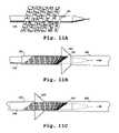
- FIGS. 10A-10Cillustrate one embodiment of a method for loading the stent of the invention into the proximal end of a catheter
- FIGS. 11A-11Cillustrate another embodiment of a method for loading the stent of the invention into the proximal end of a catheter.
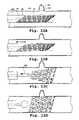
- FIGS. 12A-12Dillustrate steps in the use of the stent in treating a neuroaneurysm, in accordance with the method of the invention.
- the present inventionincludes, in one aspect, a stent adapted for advancement through a catheter in a upstream to downstream direction to a target vessel site, in a contracted stent condition, and expulsion from the catheter, downstream end first, and radial expansion at the target site, to engage the walls of the vessel.
- the stentis formed of a continuous helical ribbon formed of a preferably shape-memory alloy, and has a bending-stiffness gradient along its length due to (i) a gradient of ribbon width, (ii) a gradient of ribbon thickness, and/or (iii) a gradient of size or number of openings formed in the stent ribbon.
- the stentis preferably graftless, i.e., it consists of a metal coil alone without a woven or film-like graft formed over the coil or between the coil windings, and is preferably formed of a shape-memory alloy, as discussed below.
- bending-stiffness gradientis meant a difference in bending stiffness, as measured by amount or degree of stent bending away from its long axis per force applied; that is, a region of lesser bending stiffness in the stent will exhibit greater bending in response to a given force applied in a direction normal to the stent long axis than a region of greater bending stiffness.
- the stiffness gradientis in a direction of decreasing stiffness on progressing from upstream to the downstream end of the stent, that is, from the more proximal to the more distal stent end, with the stent placed in a catheter.
- the stiffness gradientmay be discontinuous, meaning that the gradient is formed of two or more segments of substantially uniform stiffness, or may be continuous along the length of the stent.
- FIGS. 1-5variable ribbon width
- FIGS. 6 and 7thickness
- number of openingsFIG. 8
- FIG. 1is a side view of one embodiment of a stent 10 in accordance with the invention and is composed of a continuous helical ribbon, e.g., a coil, comprising a flat, thin and biocompatible material, such as a polymer or metal, having thermal shape memory.
- Stent 10incorporates non-uniform helical winding widths in a continuous helical ribbon having an upstream portion 12 and a downstream portion 14 .
- the downstream portioncan comprise from about 3 ⁇ 5 to 4 ⁇ 5 of the total length.
- the stentcan have a gradient of ribbon widths, with greater to lesser widths progressing in an upstream-to-downstream direction.
- the ribbon widthscan be substantially uniform over the upstream half of the stent 10 shown at 12 , and decrease substantially uniformly over the downstream half of the stent as shown at 14 .
- the upstream ribbon widthis about 50 mils, decreasing in increments of 10 mils at every other winding, down to about 10 mils in the downstream region of the stent.
- the downstream portioncan comprise a region of reduced winding width which decreases substantially uniformly over the downstream half of the stent.
- the width, indicated by arrow 16 , of the ribbon windings in the upstream portionis at least ten times, and more preferably at least 25 times, the ribbon thickness as indicated at 20 .
- the ribbon width in the upstream portionis at least two times the width in the narrowest winding in the downstream portion.
- the ribbon width 16 in the upstream portion 12is at least two times the smallest ribbon width 17 in the downstream portion.
- the ribbon widths in the upstream portioncan be between 25 and 75 mils, and the smallest winding width in the downstream portion can be between 5 and 15 mils.
- the thickness 20is constant along the length of the stent.
- the ribbon thicknessis preferably between about 0.5 and 2 mils.
- the ribbonis capable of existing in a contracted condition ( FIG. 1 ) and a radially expanded condition ( FIG. 4 ).
- the diameter in the contracted condition as indicated by arrow 22can be between about 10 and 30 mils.
- the diameter of the fully expanded conditioncan be between about 40 and 125 mils.
- the stentcan be manufactured to have a length and diameter which are suitable for a particular therapeutic application.
- the length in the contracted conditioncan be between about 50 mm to 100 mm.
- the ratio of the length of the stent in the contracted condition divided by the length in the expanded condition(L c /L e ) will be approximately equal to the ratio of diameter of the stent in the expanded condition divided by the diameter in the contracted condition (D 10 /d 10 ).
- a stent having a length of 50 mm and a diameter of 0.5 mm in a contracted conditionwill expand to a length of 10 mm and a diameter of 2.5 mm.
- the stentcan include one or more regions of lesser ribbon width intermediate the ends of the stent.
- the stent 30comprises non-uniform helical winding widths in a continuous helical ribbon with regions of greater and lesser ribbon widths interspersed with one another and includes regions of greater ribbon width shown at 32 , 36 , 38 and regions of lesser ribbon width shown at 34 , 37 and at the downstream end 39 .
- the ribbon thicknesscan be between 0.5 and 2 mils
- the greater ribbon widthcan be between 25 and 75 mils
- the lesser ribbon widthcan be between 5 and 15 mils.
- Stent 30can be manufactured by laser cutting of a nitinol hypotube, and can include openings as described hereinabove.
- the wall of the stentcan include a plurality of openings disposed along the length of the helical ribbon.
- the shape of the openingscan be round, oval, square, rectangular, diamond, hexagon, or polygon, and the number, size, shape of openings can be varied.
- a preferred openingis a crossed-beam shape such as an “X”, “+”, “Z”, or “I” shape.
- each openinghas one beam axis substantially transverse to the longitudinal axis of the contracted stent.
- One beamcan be aligned transversely to the other.
- An example of a shape for the openingis illustrated at 17 in FIG. 1 .
- the openingsare “I” shaped whose “I” axis is substantially transverse to the longitudinal axis of the contracted stent.
- FIG. 2Another example of a suitable opening is shown in FIG. 2 which includes a modified “Z” shaped opening.
- the angle ⁇ between an elongated central portion 15 and a terminal crossed-beam 18is about 135° C.
- the openingscan be formed using conventional metal working processes such as die and punch, laser cutting, or chemical etching.
- the stentcan incorporate uniform helical winding widths in a continuous helical ribbon having portions which have different densities of openings, i.e., different numbers and or sizes of openings per unit length.
- the preferred shape of the openingsinclude those described hereinabove.
- the density of openingsincreases from the upstream toward the downstream direction.
- certain regions having low density of openingscan be interspersed with regions having higher density of openings.
- certain regionscan lack openings, while adjacent portions include openings.
- the thickness of the stent 60is constant along the length ( FIG. 8 ).
- the ribbon thicknessis preferably between about 0.5 and 2 mils.
- the stentcan be made from a shape-retaining metal alloy using the manufacturing methods described herein.
- the stentcan incorporate non-uniform wall thickness in a continuous helical ribbon as exemplified by stent 40 ( FIGS. 6 and 7 ).
- the stent 40has uniform winding widths, preferably between 25 and 75 mils, along the length of the ribbon.
- the stentincludes an upstream portion 42 and a downstream portion 44 , which are the same length in this embodiment. In other embodiments, the downstream portion can comprise from about 3 ⁇ 5 to 4 ⁇ 5 of the total length.
- the width as indicated by arrow 50 of the ribbon windings in the upstream portionis at least ten times, and more preferably at least 25 times, the ribbon thickness indicated by arrows 46 .
- the ribbon thickness, indicated at 46 , in the upstream portionis at least about two times the smallest ribbon thickness, indicated at 48 , in the downstream portion.
- the ribbon thickness in the upstream portioncan be between 1 and 4 mils, and the smallest winding width in the downstream portion can be between 0.5 and 2 mils.
- the upstream portioncan comprise a region of constant winding thickness.
- the downstream portioncan comprise a region of reduced winding thickness which decreases substantially uniformly over the downstream half of the stent.
- the upstream ribbon thicknessis about 2 mil, decreasing in increments of about 0.5 mils at each winding in the downstream region to final thickness of about 0.5 mil.
- the winding thicknesscan decrease substantially uniformly over the whole length of the stent, from the upstream end to the downstream end.
- the stent 40can include openings, and preferably crossbeam openings, as described hereinabove.
- the hypotubeis subjected to centerless grinding to a wall thickness which tapers at one end, for example, having a wall thickness of 2 mil at the upstream portion 42 to about 0.5 mil at the downstream portion 44 .
- the remaining manufacturing stepsare as described herein.
- the stentcan incorporate along its length, combinations of more than one of the features as described herein of variable winding width, thickness, or density of openings.
- the stent 70( FIG. 9 ) includes both decreasing winding widths toward the downstream end and also an increase in density of openings toward the downstream end.
- the stentpreferably exhibits a relatively high degree of biocompatibility since it is implanted in the body.
- Suitable materials for the stentinclude ELGILOY (available from Carpenter Technology Corporation of Reading, Pa.) and PHYNOX (available from Metal Imphy of Imphy, France). Both of these metals are cobalt-based alloys which also include chromium, iron, nickel and molybdenum.
- Other materials for a self-expanding stentinclude 316 stainless steel and MP35N alloy which are available from Carpenter Technology Corporation and Latrobe Steel Company of Latrobe, Pa., and superelastic Nitinol nickel-titanium alloy which is available from Shape Memory Applications of Santa Clara, Calif. Nitinol alloy contains about 45% titanium.
- the shape-memory alloyhas a final austentite transition temperature of between about 25° C. and 37° C. This feature allows the stent to be moved through the catheter in a stress-induced martensitic or superelastic state, and assume its preformed, austenitic shape when expelled from the catheter by removing the stress imposed on the stent by the inner catheter wall and causing the now unstressed stent to transform from stress-induced martensite into austentite and thus regaining its austentitic shape.
- the shape-memory alloyhas a transition temperature M d greater than 37° C.
- the alloyretains sufficient stress-induced martensitic property to allow placement of the stent at or above its A f .
- thisallows the stent to be moved through the catheter in a stress-induced martensitic (SIM) state, and recover its preformed, austentitic shape when released from the constraints of the catheter, at a temperature that may be substantially above the final austentite temperature without significant plastic, or otherwise permanent deformation.
- the final austentite temperaturemay be quite low, e.g., 4° C., or it may be room temperature of higher.
- Nitinol cylindrical tubes having a final austentitic temperature between about 25° C. and 45° C., preferably about 25° C. and 37° C.can be prepared according to known methods.
- a nitinol hypotubee.g., 8 mil wall thickness
- the stent patternis cut by a laser (e.g., as described by Madou in Fundamentals of Microfabrication, CRC Press, 1997). Both inner and outer surfaces are polished to a mirror finish using electro-polish techniques (e.g., as described by Madou, 1997).
- a gold coatis applied by ion beam assist.
- the ribbonis formed at the expanded condition ( FIG. 4 ), corresponding to the final deployed size (e.g., about 2-4 mm outer diameter), and heated to a temperature above the transition temperature.
- the ribbonis then subjected to thermoelastic martensitic transformation (e.g., as described in U.S. Pat. No. 5,190,546 incorporated by reference in its entirety herein) by cooling below the transition temperature range of the alloy and deformation to the contracted condition suitable for use within an intraluminal catheter.
- the stentcan be rolled using a rod having a notch at one end which engages the downstream end of the stent.
- the transition temperaturecan be modified by varying the ratios of each metal in the alloy and in the present invention preferably is within the range between about 25° C. to 45° C. at which the stent expands. A more preferred transition temperature range is between about 25° C. to 37° C.
- the alloycan comprise 55% nickel, and 45% titanium which gives a transition temperature of about 32° C. to 33° C., which is below body temperature but above room temperature.
- Nitinol cylindrical tubes having a martensite temperature M D below which the alloy can assume a stress-induced martensitic condition while being stressed to the extent necessary to place or otherwise use the device, of greater than about 37° C., preferably greater than about 40° C.,are also prepared according to known methods, e.g., U.S. Pat. No. 4,505,767.
- an ideal alloywould act, at about 37° C., as a constant force spring over a strain range up to about 5% or more. This is a measurement of the degree to which an alloy, at a given temperature, can be strained in a purely austentitic state by the formation of stress-induced martensite without significant plastic deformation.
- the strain caused by the application of a given stress at a given temperatureis substantially recoverable.
- the maximum stress realizedoccurs sometime during the process of placing a nitinol device at a given temperature. Accordingly, a suitable alloy will provide a device that is capable of substantially recovering its austentitic shape without significant plastic deformation, upon placement in the body.
- the helical stentis loaded into a catheter as illustrated in FIGS. 10A-10C .
- the catheter and loaded stentform a device in accordance with another aspect of the invention.
- the devicemay additionally include a pusher wire for advancing the stent through the lumen of the catheter, as described below.
- the stentPrior to loading, the stent can be retained in a contracted condition, e.g. within a cartridge 80 .
- the stentcan be wrapped around a mandrel (not represented) prior to placement within the cartridge.
- the downstream end of the stentis loaded into hub 84 of a delivery system such as a catheter 86 .
- Depression of plunger 88pushes the stent from its holding chamber 90 into the distal end 92 of the cartridge.
- a pusher wire 94is then introduced into the hub of the catheter.
- the inner wall of the downstream end of the stentfrictionally engages end ball 96 mounted to the distal end of the pusher wire 94 .
- the pusher wireis then pushed downstream through the catheter in order to advance the stent, in a contracted condition, to the target site.
- the stentis dragged through the catheter by the end ball near the tip which drags the stent near (but not at) its downstream end.
- FIGS. 11A-11CAnother method for loading the stent into a catheter uses a pusher wire 180 having a distal notch 182 adapted to hold the downstream end of the stent as illustrated in FIGS. 11A-11C .
- the wirecan have more than one notch along its length for attachment to more than one location on the stent (not illustrated).
- the pusher wire 180With the stent at a temperature below the transition temperature, the pusher wire 180 is rotated along its longitudinal axis to wind the stent to its contracted condition.
- the stentis manually inserted into and retained within a retaining sleeve 184 .
- An example of a suitable sleeveis a 15-20 cm section of polymeric microcatheter (Target Therapeutics, Freemont, Calif.).
- the sleeveis positioned at the opening of the hub 186 of catheter 188 and the stent is advanced in its contracted state from the sleeve and into the catheter (as indicated by arrow
- the stentis used in the treatment of a variety of vascular lesions.
- This aspectwill be illustrated in FIGS. 12A-12D using stent 10 of the invention in a method for treating a neurovascular aneurysm.
- a catheter 86is guided within the lumen 100 of a vessel 102 to the lesion site using fluoroscopy and standard angiographic techniques ( FIG. 12A ).
- the pusher wire 94is held steady and the catheter is retracted in an upstream direction, as indicated by arrow 106 to partially release the stent 10 downstream end first ( FIG. 12B ).
- the stentDuring release from the catheter, the stent is “naked” and free-moving; that is, it is not mounted on a balloon, constrained by a sheath, or held in place by a tethering wire.
- the stentdoes not deploy while partially outside of the catheter ( FIG. 12B ) and can be repositioned or removed as desired.
- the pusher wireis held steady, and the catheter is retracted, as shown by arrow 106 , to fully expel the stent ( FIG. 12B ).
- Warming of the stent to body temperature at the target sitecauses the stent to expand radially against the vessel walls at the target site.
- the expansioncauses release of the end ball, allowing withdrawal of the pusher wire, as shown by arrow 108 ( FIGS. 12C , 12 D) to complete the procedure.
- the stentdeploys once it is completely outside the catheter ( FIG. 12D ).
- the pusher wireWhen using a pusher wire having a terminal notch, the pusher wire is pushed downstream through the catheter in order to advance the stent, in a contracted condition, to the target site.
- the stentdisengages the notch upon deployment at the target site (not shown).
- a preferred helical ribbon of the inventionis effective to cover between 50% and 80%, and preferably between 65% and 80%, of the surface area of the vessel region containing the fully expanded stent.
- the length of the stentis selected so that in the expanded state, it extends beyond both sides of the mouth of the aneurysm.
- the stent of the present inventioncan be used in the treatment of a variety of vascular lesions such as an aneurysm, fistula, occlusion, or narrowing and is useful in treating targets located in tortuous and narrow vessels, for example in the neurovascular system, or in certain sites within the coronary vascular system, or in sites within the peripheral vascular system such as superficial femoral, popliteal, or renal arteries.
- vascular lesionssuch as an aneurysm, fistula, occlusion, or narrowing
- targets located in tortuous and narrow vesselsfor example in the neurovascular system, or in certain sites within the coronary vascular system, or in sites within the peripheral vascular system such as superficial femoral, popliteal, or renal arteries.
- the stentincorporates longitudinal gradients of structural features to achieve the flexibility, rate of radial expansion from a contracted to an expanded state, coverage of void space, and radial strength which are desired for its intended use.
- the ribbon widthcan be selected during manufacture.
- stent 10is substantially cylindrical in both its contracted and expanded conditions.
- the greater ribbon width along the upstream portion of the stentpromotes slower expansion after the stent is released form the catheter, relative to the expansion of a stent having uniform winding widths equal to a smallest winding width in the downstream portion.
- the slower expansionadvantageously reduces the risk of trauma to the vessel wall.
- the greater ribbon widthgives more surface coverage of the vessel wall and also provides more uniform apposition against the wall which lowers hemodynamic turbulence and lowers the risk of vascular thrombosis.
- Stent 10incorporates downstream portions having relatively lesser ribbon widths. As compared to a stent having uniform ribbon widths equal to the largest winding width in the upstream portion, the lessor ribbon widths provide a decrease in stiffness to the stent which increases the angle of bend through which the stent can be advanced in a contracted condition. This is especially important for advancing the stent within a catheter positioned within a tortuous vessel. Higher flexibility also allows the stent to conform to vessel curvature at the target site. Stent 30 includes intermediate portions having lessor winding widths, which also increase the flexibility of the stent.
- the ribbon thicknesscan be varied as in stent 40 , with greater thickness generally slower rate of expansion above the transition temperature, and greater radial strength, as compared to thinner ribbon windings. Thinner winding widths generally confer increased flexibility. Stent 40 incorporates downstream portions having relatively lesser ribbon thickness. As compared to a stent having uniform ribbon thickness equal to the largest winding width in the upstream portion, the lessor ribbon thickness provides a decrease in stiffness to the stent which increases the angle of bend through which the stent can be advanced in a contracted condition. This is especially important for advancing the stent within a catheter positioned within a tortuous blood vessel. Higher flexibility also allows the stent to conform to vessel curvature at the target site. It will be recognized that a stent can include intermediate portions having lessor winding thickness, in analogy with stent 30 , which can also increase the flexibility of the stent.
- the ribbon wall of the stentcan incorporate openings.
- the shape, orientation, and size of the openingscan be selected during manufacture.
- the density of openingscan influence the radial strength of the stent, the rate of expansion, the flexibility and the area of surface coverage.
- Different portions of a stentcan have different density of openings, or different sizes and shapes of openings, as shown in FIGS. 7 and 8 . Greater density of openings in ribbon windings generally gives greater flexibility.
- Stent 60for example, incorporates downstream portions having relatively greater density of openings. As compared to a stent having uniform density of openings along the ribbon equal to the lowest density of openings in the upstream portion, the higher density of openings provides a decrease in stiffness to the stent which increases the angle of bend through which the stent can be advanced in a contracted condition. This is especially important for advancing the stent within a catheter positioned within a tortuous vessel.
- a stentcan include intermediate portions having regions of higher or lower density of openings which can also increase the flexibility of the stent.
- Applicanthas determined that a shape which incorporates a “crossed-beam” opening disposed along the length of the helical ribbon, where each opening has at least one beam axis substantially transverse to the longitudinal axis of the stent, has the advantage of facilitating the bending of a stent, in the contracted condition, in both a direction longitudinal to the axis of the stent and in a direction transverse to the longitudinal axis of the stent. For a stent in the expanded condition, such openings minimize the size of the opening, to give greater surface coverage, while maximizing the radial strength of the stent.
- An example of a preferred openingis an I-beam shaped opening having the “I” axis transverse to the longitudinal axis of the stent in the contracted condition.
- Another exampleis a “Z” shaped opening where the central portion of the “Z” is linearly extended and is transverse to the longitudinal axis of the stent in the contracted state.
- the size and shape of the openingscan be varied to increase or decrease the contact area between the stent and the vessel wall.
- the openings and the spacing between adjacent ribbon windingscontribute to void space which is needed to promote efficient endothelial-cell growth on and around the stent.
- a void space of about 15% to 50%is preferred.
- the present inventionprovides a stent having a variety of features which can be varied during the manufacturing process in order to optimize the structure of the stent for its intended use. More than one feature, such as width, thickness, or shape or density of openings can be combined, to achieve desired flexibility, rate of expansion, or area of surface coverage.
- stent 70incorporates variations in both helical windings widths and density of openings.
- the stent of the inventionpreferably includes thin wall construction which contributes to greater lumen diameter in the stent region, and minimizes blood flow turbulence at the upstream edge of the stent, thereby reducing the risk of blood clotting.
- the stentpreferably is manufactured to minimize adverse effects, such as thrombosis, which can occur during use such as a result of hemodynamic turbulence, internal hyperplasia, and reaction to a foreign body.
- the manufacturing processesincludes an electro-polishing step to give the stent a mirror finish a gold coating step to improve biocompatibility.
- the stentcan be coated to enhance radiopacity, such as by using gold or another radiopaque metal. It can be coated with drugs or chemical agents to promote faster and more complete clotting of the aneurysm sac, to minimize the thromobogenicity of the stent in the artery, and to provide other functions. It can be covered with an autologous or synthetic graft, or coated to fill the void areas of the stent.
Landscapes
- Health & Medical Sciences (AREA)
- Engineering & Computer Science (AREA)
- Biomedical Technology (AREA)
- Cardiology (AREA)
- Oral & Maxillofacial Surgery (AREA)
- Transplantation (AREA)
- Heart & Thoracic Surgery (AREA)
- Vascular Medicine (AREA)
- Life Sciences & Earth Sciences (AREA)
- Animal Behavior & Ethology (AREA)
- General Health & Medical Sciences (AREA)
- Public Health (AREA)
- Veterinary Medicine (AREA)
- Media Introduction/Drainage Providing Device (AREA)
- Materials For Medical Uses (AREA)
- Prostheses (AREA)
Abstract
Description
Claims (17)
Priority Applications (1)
| Application Number | Priority Date | Filing Date | Title |
|---|---|---|---|
| US11/069,613US7520893B2 (en) | 1999-04-15 | 2005-03-01 | Method for treating neurovascular aneurysms |
Applications Claiming Priority (8)
| Application Number | Priority Date | Filing Date | Title |
|---|---|---|---|
| US12975799P | 1999-04-15 | 1999-04-15 | |
| US12966799P | 1999-04-15 | 1999-04-15 | |
| US12966899P | 1999-04-15 | 1999-04-15 | |
| US12975899P | 1999-04-15 | 1999-04-15 | |
| US12967299P | 1999-04-15 | 1999-04-15 | |
| US09/548,683US6860899B1 (en) | 1999-04-15 | 2000-04-13 | Method for treating neurovascular aneurysms |
| PCT/US2003/001215WO2004064683A1 (en) | 1999-04-15 | 2003-01-15 | Stent with variable stiffness |
| US11/069,613US7520893B2 (en) | 1999-04-15 | 2005-03-01 | Method for treating neurovascular aneurysms |
Related Parent Applications (1)
| Application Number | Title | Priority Date | Filing Date |
|---|---|---|---|
| US09/548,683ContinuationUS6860899B1 (en) | 1999-04-15 | 2000-04-13 | Method for treating neurovascular aneurysms |
Publications (2)
| Publication Number | Publication Date |
|---|---|
| US20050149164A1 US20050149164A1 (en) | 2005-07-07 |
| US7520893B2true US7520893B2 (en) | 2009-04-21 |
Family
ID=42561212
Family Applications (4)
| Application Number | Title | Priority Date | Filing Date |
|---|---|---|---|
| US09/548,683Expired - Fee RelatedUS6860899B1 (en) | 1999-04-15 | 2000-04-13 | Method for treating neurovascular aneurysms |
| US09/548,172Expired - Fee RelatedUS6746475B1 (en) | 1999-04-15 | 2000-04-13 | Stent with variable stiffness |
| US10/863,411AbandonedUS20040220663A1 (en) | 1999-04-15 | 2004-06-08 | Stent with variable stiffness |
| US11/069,613Expired - Fee RelatedUS7520893B2 (en) | 1999-04-15 | 2005-03-01 | Method for treating neurovascular aneurysms |
Family Applications Before (3)
| Application Number | Title | Priority Date | Filing Date |
|---|---|---|---|
| US09/548,683Expired - Fee RelatedUS6860899B1 (en) | 1999-04-15 | 2000-04-13 | Method for treating neurovascular aneurysms |
| US09/548,172Expired - Fee RelatedUS6746475B1 (en) | 1999-04-15 | 2000-04-13 | Stent with variable stiffness |
| US10/863,411AbandonedUS20040220663A1 (en) | 1999-04-15 | 2004-06-08 | Stent with variable stiffness |
Country Status (8)
| Country | Link |
|---|---|
| US (4) | US6860899B1 (en) |
| EP (2) | EP1173110B1 (en) |
| JP (1) | JP2002541911A (en) |
| AT (1) | ATE435626T1 (en) |
| AU (3) | AU772969B2 (en) |
| CA (2) | CA2370180C (en) |
| DE (1) | DE60042520D1 (en) |
| WO (2) | WO2000062711A1 (en) |
Cited By (30)
| Publication number | Priority date | Publication date | Assignee | Title |
|---|---|---|---|---|
| US20060136041A1 (en)* | 2004-12-17 | 2006-06-22 | Schmid Eric V | Slide-and-lock stent |
| US20100131048A1 (en)* | 2008-10-10 | 2010-05-27 | Reva Medical, Inc. | Expandable slide and lock stent |
| US20110166588A1 (en)* | 2010-01-04 | 2011-07-07 | Connor Robert A | Aneurysm embolization by rotational accumulation of mass |
| US8172894B2 (en) | 2007-01-26 | 2012-05-08 | Reva Medical, Inc. | Circumferentially nested expandable device |
| US20120277842A1 (en)* | 2011-04-26 | 2012-11-01 | Christopher Gerard Kunis | Method and device for treatment of hypertension and other maladies |
| US8414635B2 (en) | 1999-02-01 | 2013-04-09 | Idev Technologies, Inc. | Plain woven stents |
| US8419788B2 (en) | 2006-10-22 | 2013-04-16 | Idev Technologies, Inc. | Secured strand end devices |
| US8460363B2 (en) | 2007-11-30 | 2013-06-11 | Reva Medical, Inc. | Axially-radially nested expandable device |
| US8512394B2 (en) | 2004-07-21 | 2013-08-20 | Reva Medical Inc. | Balloon expandable crush-recoverable stent device |
| US8523936B2 (en) | 2010-04-10 | 2013-09-03 | Reva Medical, Inc. | Expandable slide and lock stent |
| US8617235B2 (en) | 2005-08-02 | 2013-12-31 | Reva Medical, Inc. | Axially nested slide and lock expandable device |
| US8876881B2 (en) | 2006-10-22 | 2014-11-04 | Idev Technologies, Inc. | Devices for stent advancement |
| US8974487B2 (en) | 2008-05-01 | 2015-03-10 | Aneuclose Llc | Aneurysm occlusion device |
| US9023094B2 (en) | 2007-06-25 | 2015-05-05 | Microvention, Inc. | Self-expanding prosthesis |
| US9023095B2 (en) | 2010-05-27 | 2015-05-05 | Idev Technologies, Inc. | Stent delivery system with pusher assembly |
| US9050205B2 (en) | 2004-05-25 | 2015-06-09 | Covidien Lp | Methods and apparatus for luminal stenting |
| US9114001B2 (en) | 2012-10-30 | 2015-08-25 | Covidien Lp | Systems for attaining a predetermined porosity of a vascular device |
| US9125659B2 (en) | 2004-05-25 | 2015-09-08 | Covidien Lp | Flexible vascular occluding device |
| US9138232B2 (en) | 2011-05-24 | 2015-09-22 | Aneuclose Llc | Aneurysm occlusion by rotational dispensation of mass |
| US9149378B2 (en) | 2005-08-02 | 2015-10-06 | Reva Medical, Inc. | Axially nested slide and lock expandable device |
| US9157174B2 (en) | 2013-02-05 | 2015-10-13 | Covidien Lp | Vascular device for aneurysm treatment and providing blood flow into a perforator vessel |
| US9320590B2 (en) | 2006-02-22 | 2016-04-26 | Covidien Lp | Stents having radiopaque mesh |
| US9358140B1 (en) | 2009-11-18 | 2016-06-07 | Aneuclose Llc | Stent with outer member to embolize an aneurysm |
| US9393021B2 (en) | 2004-05-25 | 2016-07-19 | Covidien Lp | Flexible vascular occluding device |
| US9408732B2 (en) | 2013-03-14 | 2016-08-09 | Reva Medical, Inc. | Reduced-profile slide and lock stent |
| US9452070B2 (en) | 2012-10-31 | 2016-09-27 | Covidien Lp | Methods and systems for increasing a density of a region of a vascular device |
| US9943427B2 (en) | 2012-11-06 | 2018-04-17 | Covidien Lp | Shaped occluding devices and methods of using the same |
| US10004618B2 (en) | 2004-05-25 | 2018-06-26 | Covidien Lp | Methods and apparatus for luminal stenting |
| US10028747B2 (en) | 2008-05-01 | 2018-07-24 | Aneuclose Llc | Coils with a series of proximally-and-distally-connected loops for occluding a cerebral aneurysm |
| US10716573B2 (en) | 2008-05-01 | 2020-07-21 | Aneuclose | Janjua aneurysm net with a resilient neck-bridging portion for occluding a cerebral aneurysm |
Families Citing this family (159)
| Publication number | Priority date | Publication date | Assignee | Title |
|---|---|---|---|---|
| US6860899B1 (en)* | 1999-04-15 | 2005-03-01 | Boston Scientific Scimed, Inc. | Method for treating neurovascular aneurysms |
| US6899730B1 (en) | 1999-04-15 | 2005-05-31 | Scimed Life Systems, Inc. | Catheter-stent device |
| US6585760B1 (en)* | 2000-06-30 | 2003-07-01 | Vascular Architects, Inc | AV fistula and function enhancing method |
| US7037330B1 (en)* | 2000-10-16 | 2006-05-02 | Scimed Life Systems, Inc. | Neurovascular stent and method |
| DE10118944B4 (en) | 2001-04-18 | 2013-01-31 | Merit Medical Systems, Inc. | Removable, essentially cylindrical implants |
| US8252040B2 (en) | 2001-07-20 | 2012-08-28 | Microvention, Inc. | Aneurysm treatment device and method of use |
| AU2002320456A1 (en) | 2001-07-26 | 2003-02-17 | Alveolus Inc. | Removable stent and method of using the same |
| DE10213369A1 (en)* | 2002-03-21 | 2003-10-02 | Biotronik Mess & Therapieg | Stent for treating or preventing aneurysms comprises a lattice-like peripheral wall including a hollow chamber open on its front sides |
| US8075585B2 (en)* | 2002-08-29 | 2011-12-13 | Stryker Corporation | Device and method for treatment of a vascular defect |
| US20040093056A1 (en) | 2002-10-26 | 2004-05-13 | Johnson Lianw M. | Medical appliance delivery apparatus and method of use |
| US7875068B2 (en) | 2002-11-05 | 2011-01-25 | Merit Medical Systems, Inc. | Removable biliary stent |
| US7959671B2 (en) | 2002-11-05 | 2011-06-14 | Merit Medical Systems, Inc. | Differential covering and coating methods |
| US7637942B2 (en) | 2002-11-05 | 2009-12-29 | Merit Medical Systems, Inc. | Coated stent with geometry determinated functionality and method of making the same |
| US7527644B2 (en) | 2002-11-05 | 2009-05-05 | Alveolus Inc. | Stent with geometry determinated functionality and method of making the same |
| US7025791B2 (en)* | 2002-12-02 | 2006-04-11 | Gi Dynamics, Inc. | Bariatric sleeve |
| WO2004049982A2 (en) | 2002-12-02 | 2004-06-17 | Gi Dynamics, Inc. | Bariatric sleeve |
| US7608114B2 (en) | 2002-12-02 | 2009-10-27 | Gi Dynamics, Inc. | Bariatric sleeve |
| US7678068B2 (en)* | 2002-12-02 | 2010-03-16 | Gi Dynamics, Inc. | Atraumatic delivery devices |
| US20050033410A1 (en)* | 2002-12-24 | 2005-02-10 | Novostent Corporation | Vascular prothesis having flexible configuration |
| US20040158314A1 (en)* | 2002-12-24 | 2004-08-12 | Novostent Corporation | Ribbon-type vascular prosthesis having stress-relieving articulation and methods of use |
| US7846198B2 (en) | 2002-12-24 | 2010-12-07 | Novostent Corporation | Vascular prosthesis and methods of use |
| US20050165469A1 (en)* | 2002-12-24 | 2005-07-28 | Michael Hogendijk | Vascular prosthesis including torsional stabilizer and methods of use |
| US20040193246A1 (en)* | 2003-03-25 | 2004-09-30 | Microvention, Inc. | Methods and apparatus for treating aneurysms and other vascular defects |
| US7771463B2 (en)* | 2003-03-26 | 2010-08-10 | Ton Dai T | Twist-down implant delivery technologies |
| EP2226040A1 (en) | 2003-03-26 | 2010-09-08 | Cardiomind, Inc. | Stent delivery system with torsionally compressed stent |
| US20040193179A1 (en)* | 2003-03-26 | 2004-09-30 | Cardiomind, Inc. | Balloon catheter lumen based stent delivery systems |
| US20050209672A1 (en)* | 2004-03-02 | 2005-09-22 | Cardiomind, Inc. | Sliding restraint stent delivery systems |
| US7637934B2 (en) | 2003-03-31 | 2009-12-29 | Merit Medical Systems, Inc. | Medical appliance optical delivery and deployment apparatus and method |
| US7604660B2 (en) | 2003-05-01 | 2009-10-20 | Merit Medical Systems, Inc. | Bifurcated medical appliance delivery apparatus and method |
| US20040260377A1 (en)* | 2003-06-17 | 2004-12-23 | Medinol, Ltd. | Shape memory alloy endoprosthesis delivery system |
| US20040260384A1 (en)* | 2003-06-17 | 2004-12-23 | Medtronic Ave | Superelastic coiled stent |
| AU2004305450B2 (en) | 2003-12-09 | 2009-01-08 | Gi Dynamics, Inc. | Intestinal sleeve |
| US7651521B2 (en) | 2004-03-02 | 2010-01-26 | Cardiomind, Inc. | Corewire actuated delivery system with fixed distal stent-carrying extension |
| US7901447B2 (en) | 2004-12-29 | 2011-03-08 | Boston Scientific Scimed, Inc. | Medical devices including a metallic film and at least one filament |
| US8992592B2 (en) | 2004-12-29 | 2015-03-31 | Boston Scientific Scimed, Inc. | Medical devices including metallic films |
| US20050209670A1 (en)* | 2004-03-02 | 2005-09-22 | Cardiomind, Inc. | Stent delivery system with diameter adaptive restraint |
| US8998973B2 (en) | 2004-03-02 | 2015-04-07 | Boston Scientific Scimed, Inc. | Medical devices including metallic films |
| US20050209671A1 (en)* | 2004-03-02 | 2005-09-22 | Cardiomind, Inc. | Corewire actuated delivery system with fixed distal stent-carrying extension |
| US8617234B2 (en)* | 2004-05-25 | 2013-12-31 | Covidien Lp | Flexible vascular occluding device |
| US20050283166A1 (en)* | 2004-06-17 | 2005-12-22 | Secant Medical, Llc | Expandible snare |
| US20070292478A1 (en) | 2004-08-30 | 2007-12-20 | Popowski Youri | Medical Implant Provided with Inhibitors of Atp Synthesis |
| US20060058869A1 (en)* | 2004-09-14 | 2006-03-16 | Vascular Architects, Inc., A Delaware Corporation | Coiled ladder stent |
| US7018403B1 (en)* | 2004-09-14 | 2006-03-28 | Advanced Cardiovascular Systems, Inc. | Inclined stent pattern for vulnerable plaque |
| WO2006032290A2 (en)* | 2004-09-22 | 2006-03-30 | Dendron Gmbh | Implant insert system |
| US7914570B2 (en)* | 2004-10-07 | 2011-03-29 | Boston Scientific Scimed, Inc. | Non-shortening helical stent |
| AU2005296096A1 (en)* | 2004-10-14 | 2006-04-27 | Cardiomind, Inc. | Small vessel stent designs |
| US20060085057A1 (en)* | 2004-10-14 | 2006-04-20 | Cardiomind | Delivery guide member based stent anti-jumping technologies |
| CN100425206C (en)* | 2005-01-06 | 2008-10-15 | 大连大学 | Taper sleeve type iso-radius contractor for cylindrical reticular stent |
| US20060206199A1 (en)* | 2005-03-12 | 2006-09-14 | Churchwell Stacey D | Aneurysm treatment devices |
| US20060206198A1 (en)* | 2005-03-12 | 2006-09-14 | Churchwell Stacey D | Aneurysm treatment devices and methods |
| JP5523700B2 (en) | 2005-04-04 | 2014-06-18 | フレキシブル ステンティング ソリューションズ,インク. | Flexible stent |
| US8961585B2 (en)* | 2005-04-25 | 2015-02-24 | Covidien Lp | Controlled fracture connections for stents |
| US20060276886A1 (en)* | 2005-06-07 | 2006-12-07 | Cardiomind, Inc. | Ten-thousandths scale metal reinforced stent delivery guide sheath or restraint |
| US20070027522A1 (en)* | 2005-06-14 | 2007-02-01 | Chang Jean C | Stent delivery and guidewire systems |
| US20070055339A1 (en)* | 2005-08-23 | 2007-03-08 | George William R | Staged stent delivery systems |
| US8956400B2 (en)* | 2005-10-14 | 2015-02-17 | Flexible Stenting Solutions, Inc. | Helical stent |
| US20070100414A1 (en)* | 2005-11-02 | 2007-05-03 | Cardiomind, Inc. | Indirect-release electrolytic implant delivery systems |
| US7699884B2 (en)* | 2006-03-22 | 2010-04-20 | Cardiomind, Inc. | Method of stenting with minimal diameter guided delivery systems |
| US20070239268A1 (en)* | 2006-03-30 | 2007-10-11 | Lee Fox | Adhesion resistant implantable device |
| US8834554B2 (en)* | 2006-08-22 | 2014-09-16 | Abbott Cardiovascular Systems Inc. | Intravascular stent |
| US20100152828A1 (en)* | 2006-11-02 | 2010-06-17 | Pakbaz R Sean | Devices and methods for accessing and treating an aneurysm |
| JP5319546B2 (en)* | 2006-12-15 | 2013-10-16 | カーディオマインド, インコーポレイテッド | Stent system |
| US8348994B2 (en) | 2007-03-09 | 2013-01-08 | Novostent Corporation | Vascular prosthesis with alternating helical sections |
| US8002815B2 (en) | 2007-03-09 | 2011-08-23 | Novostent Corporation | Delivery system and method for vascular prosthesis |
| US9017395B2 (en) | 2007-03-09 | 2015-04-28 | Novostent Corporation | Vascular prosthesis and methods of use |
| US7988723B2 (en) | 2007-08-02 | 2011-08-02 | Flexible Stenting Solutions, Inc. | Flexible stent |
| US20090043276A1 (en)* | 2007-08-09 | 2009-02-12 | Boston Scientific Scimed, Inc. | Drug delivery device, compositions and methods relating thereto |
| US9393137B2 (en)* | 2007-09-24 | 2016-07-19 | Boston Scientific Scimed, Inc. | Method for loading a stent into a delivery system |
| US9375327B2 (en) | 2007-12-12 | 2016-06-28 | Intact Vascular, Inc. | Endovascular implant |
| US8128677B2 (en) | 2007-12-12 | 2012-03-06 | Intact Vascular LLC | Device and method for tacking plaque to a blood vessel wall |
| US10166127B2 (en) | 2007-12-12 | 2019-01-01 | Intact Vascular, Inc. | Endoluminal device and method |
| US9603730B2 (en) | 2007-12-12 | 2017-03-28 | Intact Vascular, Inc. | Endoluminal device and method |
| US10022250B2 (en) | 2007-12-12 | 2018-07-17 | Intact Vascular, Inc. | Deployment device for placement of multiple intraluminal surgical staples |
| US7896911B2 (en) | 2007-12-12 | 2011-03-01 | Innovasc Llc | Device and method for tacking plaque to blood vessel wall |
| US20090163851A1 (en)* | 2007-12-19 | 2009-06-25 | Holloway Kenneth A | Occlusive material removal device having selectively variable stiffness |
| US9402707B2 (en) | 2008-07-22 | 2016-08-02 | Neuravi Limited | Clot capture systems and associated methods |
| US9149376B2 (en) | 2008-10-06 | 2015-10-06 | Cordis Corporation | Reconstrainable stent delivery system |
| GB0818450D0 (en) | 2008-10-08 | 2008-11-12 | Angiomed Ag | Method of transferring a stent device from a crimping head to an outer sheath of a stent device delivery system |
| US20100125323A1 (en)* | 2008-11-14 | 2010-05-20 | Medtronic Vascular, Inc. | Coil Stent Delivery System and Method of Use |
| GB0900565D0 (en) | 2009-01-14 | 2009-02-11 | Isis Innovation | Stent |
| EP2413840B1 (en) | 2009-04-02 | 2016-08-17 | Endoshape, Inc. | Vascular occlusion devices |
| US8657870B2 (en)* | 2009-06-26 | 2014-02-25 | Biosensors International Group, Ltd. | Implant delivery apparatus and methods with electrolytic release |
| US8425586B2 (en)* | 2009-09-02 | 2013-04-23 | Novostent Corporation | Vascular prosthesis with stress relief slots |
| US20110218608A1 (en)* | 2009-09-10 | 2011-09-08 | Novostent Corporation | Vascular Prosthesis Delivery System and Method |
| US8403988B2 (en) | 2009-09-11 | 2013-03-26 | Depuy Spine, Inc. | Minimally invasive intervertebral staple distraction devices |
| CA2768567C (en)* | 2009-09-14 | 2017-03-21 | Circulite, Inc. | Endovascular anastomotic connector device, delivery system, and methods of delivery and use |
| US9615933B2 (en)* | 2009-09-15 | 2017-04-11 | DePuy Synthes Products, Inc. | Expandable ring intervertebral fusion device |
| US8333727B2 (en)* | 2009-10-08 | 2012-12-18 | Circulite, Inc. | Two piece endovascular anastomotic connector |
| GB2476479B (en) | 2009-12-22 | 2012-06-20 | Cook Medical Technologies Llc | Implantable device |
| CA2804254C (en) | 2010-02-23 | 2016-11-01 | Medina Medical, Inc. | Devices and methods for vascular recanalization |
| US20130109987A1 (en)* | 2011-05-12 | 2013-05-02 | Medical Device Innovations Inc. | Method and device for treatment of arrhythmias and other maladies |
| US9247942B2 (en) | 2010-06-29 | 2016-02-02 | Artventive Medical Group, Inc. | Reversible tubal contraceptive device |
| EP2588042A4 (en)* | 2010-06-29 | 2015-03-18 | Artventive Medical Group Inc | Reducing flow through a tubular structure |
| US9149277B2 (en) | 2010-10-18 | 2015-10-06 | Artventive Medical Group, Inc. | Expandable device delivery |
| ES2683943T3 (en) | 2010-10-22 | 2018-09-28 | Neuravi Limited | Clot capture and removal system |
| US11259824B2 (en) | 2011-03-09 | 2022-03-01 | Neuravi Limited | Clot retrieval device for removing occlusive clot from a blood vessel |
| EP4566553A3 (en) | 2011-03-09 | 2025-08-06 | Neuravi Limited | A clot retrieval device for removing occlusive clot from a blood vessel |
| US12076037B2 (en) | 2011-03-09 | 2024-09-03 | Neuravi Limited | Systems and methods to restore perfusion to a vessel |
| EP2707077B1 (en) | 2011-05-11 | 2017-10-04 | Microvention, Inc. | Device for occluding a lumen |
| US10285831B2 (en) | 2011-06-03 | 2019-05-14 | Intact Vascular, Inc. | Endovascular implant |
| JP6179995B2 (en)* | 2011-12-05 | 2017-08-16 | ストライカー コーポレイションStryker Corporation | Reinforced stretch medical device and manufacturing method |
| US10603043B2 (en) | 2012-01-17 | 2020-03-31 | Endoshape, Inc. | Occlusion device for a vascular or biological lumen |
| CN110464520A (en) | 2012-01-25 | 2019-11-19 | 因特脉管有限公司 | Intracavitary unit and method |
| US9642700B2 (en)* | 2012-05-31 | 2017-05-09 | St. Jude Medical, Cardiology Division, Inc. | Prosthetic heart valve having a polymeric stent |
| EP2908880B1 (en)* | 2012-10-16 | 2018-12-05 | Paul A. Spence | Devices for facilitating flow from the heart to a blood pump |
| US8984733B2 (en) | 2013-02-05 | 2015-03-24 | Artventive Medical Group, Inc. | Bodily lumen occlusion |
| US9095344B2 (en) | 2013-02-05 | 2015-08-04 | Artventive Medical Group, Inc. | Methods and apparatuses for blood vessel occlusion |
| CN105073031B (en) | 2013-03-13 | 2017-10-27 | 内形有限公司 | Continuous embolic coil and its carrying method and device |
| US9433429B2 (en)* | 2013-03-14 | 2016-09-06 | Neuravi Limited | Clot retrieval devices |
| ES2708786T3 (en) | 2013-03-14 | 2019-04-11 | Neuravi Ltd | Clot recovery device to remove occlusive clots from a blood vessel |
| WO2014140092A2 (en) | 2013-03-14 | 2014-09-18 | Neuravi Limited | Devices and methods for removal of acute blockages from blood vessels |
| US9844383B2 (en) | 2013-05-08 | 2017-12-19 | Embolx, Inc. | Devices and methods for low pressure tumor embolization |
| US9205226B2 (en) | 2013-05-08 | 2015-12-08 | Embolx, Inc. | Device and methods for transvascular tumor embolization with integrated flow regulation |
| US9737306B2 (en) | 2013-06-14 | 2017-08-22 | Artventive Medical Group, Inc. | Implantable luminal devices |
| US9737308B2 (en) | 2013-06-14 | 2017-08-22 | Artventive Medical Group, Inc. | Catheter-assisted tumor treatment |
| US9636116B2 (en) | 2013-06-14 | 2017-05-02 | Artventive Medical Group, Inc. | Implantable luminal devices |
| US10149968B2 (en) | 2013-06-14 | 2018-12-11 | Artventive Medical Group, Inc. | Catheter-assisted tumor treatment |
| WO2015102988A1 (en)* | 2013-12-30 | 2015-07-09 | Stryker Corporation | Stent and method of use |
| US9510976B2 (en)* | 2014-04-29 | 2016-12-06 | Abbott Cardiovascular Systems Inc. | Devices and methods for treatment of the Eustachian tube and sinus cavity |
| US10363043B2 (en) | 2014-05-01 | 2019-07-30 | Artventive Medical Group, Inc. | Treatment of incompetent vessels |
| DE102014111117B4 (en)* | 2014-08-05 | 2017-11-16 | Acandis Gmbh & Co. Kg | Medical device for the treatment of neurovascular diseases, system and set with such a device and manufacturing method |
| EP3682821B1 (en) | 2014-11-26 | 2022-05-11 | Neuravi Limited | A clot retrieval device for removing an occlusive clot from a blood vessel |
| US10617435B2 (en) | 2014-11-26 | 2020-04-14 | Neuravi Limited | Clot retrieval device for removing clot from a blood vessel |
| US11253278B2 (en) | 2014-11-26 | 2022-02-22 | Neuravi Limited | Clot retrieval system for removing occlusive clot from a blood vessel |
| CA2972620C (en) | 2015-01-20 | 2023-08-01 | Neurogami Medical, Inc. | Micrograft for the treatment of intracranial aneurysms and method for use |
| US10736730B2 (en) | 2015-01-20 | 2020-08-11 | Neurogami Medical, Inc. | Vascular implant |
| US11484319B2 (en) | 2015-01-20 | 2022-11-01 | Neurogami Medical, Inc. | Delivery system for micrograft for treating intracranial aneurysms |
| US10857012B2 (en) | 2015-01-20 | 2020-12-08 | Neurogami Medical, Inc. | Vascular implant |
| US10925611B2 (en) | 2015-01-20 | 2021-02-23 | Neurogami Medical, Inc. | Packaging for surgical implant |
| US9433520B2 (en) | 2015-01-29 | 2016-09-06 | Intact Vascular, Inc. | Delivery device and method of delivery |
| US9375336B1 (en) | 2015-01-29 | 2016-06-28 | Intact Vascular, Inc. | Delivery device and method of delivery |
| US10993824B2 (en) | 2016-01-01 | 2021-05-04 | Intact Vascular, Inc. | Delivery device and method of delivery |
| US9550046B1 (en) | 2016-02-16 | 2017-01-24 | Embolx, Inc. | Balloon catheter and methods of fabrication and use |
| US12268824B2 (en) | 2018-07-27 | 2025-04-08 | Embolx, Inc. | Shaped catheter tip for tracking over a guidewire through turns in the vasculature |
| US11464948B2 (en) | 2016-02-16 | 2022-10-11 | Embolx, Inc. | Balloon catheters and methods of manufacture and use |
| US10350382B1 (en) | 2018-06-08 | 2019-07-16 | Embolx, Inc. | High torque catheter and methods of manufacture |
| US10813644B2 (en) | 2016-04-01 | 2020-10-27 | Artventive Medical Group, Inc. | Occlusive implant and delivery system |
| US10420563B2 (en) | 2016-07-08 | 2019-09-24 | Neurogami Medical, Inc. | Delivery system insertable through body lumen |
| EP3509509B1 (en) | 2016-09-06 | 2021-03-31 | Neuravi Limited | A clot retrieval device for removing occlusive clot from a blood vessel |
| US11660218B2 (en) | 2017-07-26 | 2023-05-30 | Intact Vascular, Inc. | Delivery device and method of delivery |
| US11065136B2 (en) | 2018-02-08 | 2021-07-20 | Covidien Lp | Vascular expandable devices |
| US11065009B2 (en) | 2018-02-08 | 2021-07-20 | Covidien Lp | Vascular expandable devices |
| US11406416B2 (en) | 2018-10-02 | 2022-08-09 | Neuravi Limited | Joint assembly for vasculature obstruction capture device |
| CN109651445B (en)* | 2019-01-22 | 2020-12-29 | 上海应用技术大学 | Preparation and application of a large sterically hindered trivalent rhodium imine complex |
| US12409298B2 (en) | 2019-08-20 | 2025-09-09 | Embolx, Inc. | Catheters and methods of manufacture and use |
| US11712231B2 (en) | 2019-10-29 | 2023-08-01 | Neuravi Limited | Proximal locking assembly design for dual stent mechanical thrombectomy device |
| US11517340B2 (en) | 2019-12-03 | 2022-12-06 | Neuravi Limited | Stentriever devices for removing an occlusive clot from a vessel and methods thereof |
| US11717308B2 (en) | 2020-04-17 | 2023-08-08 | Neuravi Limited | Clot retrieval device for removing heterogeneous clots from a blood vessel |
| US11730501B2 (en) | 2020-04-17 | 2023-08-22 | Neuravi Limited | Floating clot retrieval device for removing clots from a blood vessel |
| US11871946B2 (en) | 2020-04-17 | 2024-01-16 | Neuravi Limited | Clot retrieval device for removing clot from a blood vessel |
| US11737771B2 (en) | 2020-06-18 | 2023-08-29 | Neuravi Limited | Dual channel thrombectomy device |
| US11937836B2 (en) | 2020-06-22 | 2024-03-26 | Neuravi Limited | Clot retrieval system with expandable clot engaging framework |
| US11439418B2 (en) | 2020-06-23 | 2022-09-13 | Neuravi Limited | Clot retrieval device for removing clot from a blood vessel |
| US11395669B2 (en) | 2020-06-23 | 2022-07-26 | Neuravi Limited | Clot retrieval device with flexible collapsible frame |
| US11864781B2 (en) | 2020-09-23 | 2024-01-09 | Neuravi Limited | Rotating frame thrombectomy device |
| US11937837B2 (en) | 2020-12-29 | 2024-03-26 | Neuravi Limited | Fibrin rich / soft clot mechanical thrombectomy device |
| US12029442B2 (en) | 2021-01-14 | 2024-07-09 | Neuravi Limited | Systems and methods for a dual elongated member clot retrieval apparatus |
| US12064130B2 (en) | 2021-03-18 | 2024-08-20 | Neuravi Limited | Vascular obstruction retrieval device having sliding cages pinch mechanism |
| US11974764B2 (en) | 2021-06-04 | 2024-05-07 | Neuravi Limited | Self-orienting rotating stentriever pinching cells |
Citations (38)
| Publication number | Priority date | Publication date | Assignee | Title |
|---|---|---|---|---|
| US4503569A (en) | 1983-03-03 | 1985-03-12 | Dotter Charles T | Transluminally placed expandable graft prosthesis |
| US4505767A (en) | 1983-10-14 | 1985-03-19 | Raychem Corporation | Nickel/titanium/vanadium shape memory alloy |
| US4512338A (en) | 1983-01-25 | 1985-04-23 | Balko Alexander B | Process for restoring patency to body vessels |
| US4553545A (en) | 1981-09-16 | 1985-11-19 | Medinvent S.A. | Device for application in blood vessels or other difficultly accessible locations and its use |
| US4665918A (en) | 1986-01-06 | 1987-05-19 | Garza Gilbert A | Prosthesis system and method |
| US4760849A (en) | 1985-04-10 | 1988-08-02 | Medinvent S.A. | Planar blank and a coil spring manufactured therefrom |
| US4795485A (en) | 1985-03-01 | 1989-01-03 | E. I. Du Pont De Nemours And Company | Phenyl-substituted sulfonamides |
| US4820298A (en) | 1987-11-20 | 1989-04-11 | Leveen Eric G | Internal vascular prosthesis |
| US4830003A (en) | 1988-06-17 | 1989-05-16 | Wolff Rodney G | Compressive stent and delivery system |
| US5067957A (en) | 1983-10-14 | 1991-11-26 | Raychem Corporation | Method of inserting medical devices incorporating SIM alloy elements |
| US5108417A (en) | 1990-09-14 | 1992-04-28 | Interface Biomedical Laboratories Corp. | Anti-turbulent, anti-thrombogenic intravascular stent |
| US5217484A (en) | 1991-06-07 | 1993-06-08 | Marks Michael P | Retractable-wire catheter device and method |
| WO1993015661A1 (en) | 1992-02-06 | 1993-08-19 | Interface Biomedical Laboratories Corp. | Anti-turbulent, anti-thrombogenic intravascular stent |
| US5342387A (en) | 1992-06-18 | 1994-08-30 | American Biomed, Inc. | Artificial support for a blood vessel |
| US5484444A (en) | 1992-10-31 | 1996-01-16 | Schneider (Europe) A.G. | Device for the implantation of self-expanding endoprostheses |
| US5540712A (en) | 1992-05-01 | 1996-07-30 | Nitinol Medical Technologies, Inc. | Stent and method and apparatus for forming and delivering the same |
| US5551954A (en) | 1991-10-04 | 1996-09-03 | Scimed Life Systems, Inc. | Biodegradable drug delivery vascular stent |
| US5562641A (en) | 1993-05-28 | 1996-10-08 | A Bromberg & Co. Ltd. | Two way shape memory alloy medical stent |
| US5782907A (en) | 1995-07-13 | 1998-07-21 | Devices For Vascular Intervention, Inc. | Involuted spring stent and graft assembly and method of use |
| US5824053A (en)* | 1997-03-18 | 1998-10-20 | Endotex Interventional Systems, Inc. | Helical mesh endoprosthesis and methods of use |
| US5833694A (en) | 1995-05-25 | 1998-11-10 | Medtronic, Inc. | Stent assembly and method of use |
| US5836966A (en) | 1997-05-22 | 1998-11-17 | Scimed Life Systems, Inc. | Variable expansion force stent |
| US5860999A (en) | 1993-02-04 | 1999-01-19 | Angiomed Gmbh & Co.Medizintechnik Kg | Stent and method of using same |
| US5928217A (en) | 1996-04-09 | 1999-07-27 | Endocare, Inc. | Urological stent therapy system and method |
| US5938697A (en) | 1998-03-04 | 1999-08-17 | Scimed Life Systems, Inc. | Stent having variable properties |
| US6019779A (en) | 1998-10-09 | 2000-02-01 | Intratherapeutics Inc. | Multi-filar coil medical stent |
| US6027526A (en) | 1996-04-10 | 2000-02-22 | Advanced Cardiovascular Systems, Inc. | Stent having varied amounts of structural strength along its length |
| US6048360A (en) | 1997-03-18 | 2000-04-11 | Endotex Interventional Systems, Inc. | Methods of making and using coiled sheet graft for single and bifurcated lumens |
| US6123723A (en) | 1998-02-26 | 2000-09-26 | Board Of Regents, The University Of Texas System | Delivery system and method for depolyment and endovascular assembly of multi-stage stent graft |
| US6129755A (en) | 1998-01-09 | 2000-10-10 | Nitinol Development Corporation | Intravascular stent having an improved strut configuration |
| WO2000062711A1 (en) | 1999-04-15 | 2000-10-26 | Smart Therapeutics, Inc. | Intravascular stent and method of treating neurovascualr vessel lesion |
| US6156062A (en) | 1997-12-03 | 2000-12-05 | Ave Connaught | Helically wrapped interlocking stent |
| US6190406B1 (en) | 1998-01-09 | 2001-02-20 | Nitinal Development Corporation | Intravascular stent having tapered struts |
| US6200335B1 (en) | 1997-03-31 | 2001-03-13 | Kabushikikaisha Igaki Iryo Sekkei | Stent for vessel |
| US6261320B1 (en) | 1996-11-21 | 2001-07-17 | Radiance Medical Systems, Inc. | Radioactive vascular liner |
| US6290731B1 (en) | 1998-03-30 | 2001-09-18 | Cordis Corporation | Aortic graft having a precursor gasket for repairing an abdominal aortic aneurysm |
| US6413282B1 (en) | 1997-06-20 | 2002-07-02 | Matsushita Electric Industrial Co., Ltd. | Electrolytic capacitor and method for manufacturing the same |
| US6425915B1 (en) | 1997-03-18 | 2002-07-30 | Endotex Interventional Systems, Inc. | Helical mesh endoprosthesis and methods of use |
Family Cites Families (6)
| Publication number | Priority date | Publication date | Assignee | Title |
|---|---|---|---|---|
| WO1987004935A1 (en)* | 1986-02-24 | 1987-08-27 | Fischell Robert | An intravascular stent and percutaneous insertion system |
| DE9010130U1 (en)* | 1989-07-13 | 1990-09-13 | American Medical Systems, Inc., Minnetonka, Minn. | Instrument for attaching an expansion implant |
| US5147370A (en)* | 1991-06-12 | 1992-09-15 | Mcnamara Thomas O | Nitinol stent for hollow body conduits |
| US5833699A (en)* | 1996-04-10 | 1998-11-10 | Chuter; Timothy A. M. | Extending ribbon stent |
| US5797952A (en)* | 1996-06-21 | 1998-08-25 | Localmed, Inc. | System and method for delivering helical stents |
| US6245915B1 (en)* | 1999-05-03 | 2001-06-12 | Ciba Specialty Chemicals Corporation | Asymmetrical bisbenzotriazoles substituted by a perfluoroalkyl moiety |
- 2000
- 2000-04-13USUS09/548,683patent/US6860899B1/ennot_activeExpired - Fee Related
- 2000-04-13EPEP00928163Apatent/EP1173110B1/ennot_activeExpired - Lifetime
- 2000-04-13ATAT00928163Tpatent/ATE435626T1/ennot_activeIP Right Cessation
- 2000-04-13JPJP2000611849Apatent/JP2002541911A/ennot_activeWithdrawn
- 2000-04-13WOPCT/US2000/009886patent/WO2000062711A1/enactiveIP Right Grant
- 2000-04-13USUS09/548,172patent/US6746475B1/ennot_activeExpired - Fee Related
- 2000-04-13DEDE60042520Tpatent/DE60042520D1/ennot_activeExpired - Lifetime
- 2000-04-13AUAU46438/00Apatent/AU772969B2/ennot_activeCeased
- 2000-04-13CACA002370180Apatent/CA2370180C/ennot_activeExpired - Fee Related
- 2003
- 2003-01-15EPEP03702131Apatent/EP1583486A1/ennot_activeWithdrawn
- 2003-01-15AUAU2003203015Apatent/AU2003203015A1/ennot_activeAbandoned
- 2003-01-15CACA002512723Apatent/CA2512723A1/ennot_activeAbandoned
- 2003-01-15WOPCT/US2003/001215patent/WO2004064683A1/ennot_activeApplication Discontinuation
- 2004
- 2004-06-08USUS10/863,411patent/US20040220663A1/ennot_activeAbandoned
- 2004-07-06AUAU2004203046Apatent/AU2004203046B2/ennot_activeCeased
- 2005
- 2005-03-01USUS11/069,613patent/US7520893B2/ennot_activeExpired - Fee Related
Patent Citations (42)
| Publication number | Priority date | Publication date | Assignee | Title |
|---|---|---|---|---|
| US4553545A (en) | 1981-09-16 | 1985-11-19 | Medinvent S.A. | Device for application in blood vessels or other difficultly accessible locations and its use |
| US4512338A (en) | 1983-01-25 | 1985-04-23 | Balko Alexander B | Process for restoring patency to body vessels |
| US4503569A (en) | 1983-03-03 | 1985-03-12 | Dotter Charles T | Transluminally placed expandable graft prosthesis |
| US4505767A (en) | 1983-10-14 | 1985-03-19 | Raychem Corporation | Nickel/titanium/vanadium shape memory alloy |
| US5067957A (en) | 1983-10-14 | 1991-11-26 | Raychem Corporation | Method of inserting medical devices incorporating SIM alloy elements |
| US4795485A (en) | 1985-03-01 | 1989-01-03 | E. I. Du Pont De Nemours And Company | Phenyl-substituted sulfonamides |
| US4760849A (en) | 1985-04-10 | 1988-08-02 | Medinvent S.A. | Planar blank and a coil spring manufactured therefrom |
| US4665918A (en) | 1986-01-06 | 1987-05-19 | Garza Gilbert A | Prosthesis system and method |
| US4820298A (en) | 1987-11-20 | 1989-04-11 | Leveen Eric G | Internal vascular prosthesis |
| US4830003A (en) | 1988-06-17 | 1989-05-16 | Wolff Rodney G | Compressive stent and delivery system |
| US5108417A (en) | 1990-09-14 | 1992-04-28 | Interface Biomedical Laboratories Corp. | Anti-turbulent, anti-thrombogenic intravascular stent |
| US5217484A (en) | 1991-06-07 | 1993-06-08 | Marks Michael P | Retractable-wire catheter device and method |
| US5551954A (en) | 1991-10-04 | 1996-09-03 | Scimed Life Systems, Inc. | Biodegradable drug delivery vascular stent |
| WO1993015661A1 (en) | 1992-02-06 | 1993-08-19 | Interface Biomedical Laboratories Corp. | Anti-turbulent, anti-thrombogenic intravascular stent |
| US5540712A (en) | 1992-05-01 | 1996-07-30 | Nitinol Medical Technologies, Inc. | Stent and method and apparatus for forming and delivering the same |
| US5342387A (en) | 1992-06-18 | 1994-08-30 | American Biomed, Inc. | Artificial support for a blood vessel |
| US5484444A (en) | 1992-10-31 | 1996-01-16 | Schneider (Europe) A.G. | Device for the implantation of self-expanding endoprostheses |
| US5860999A (en) | 1993-02-04 | 1999-01-19 | Angiomed Gmbh & Co.Medizintechnik Kg | Stent and method of using same |
| US5562641A (en) | 1993-05-28 | 1996-10-08 | A Bromberg & Co. Ltd. | Two way shape memory alloy medical stent |
| US5902317A (en) | 1994-06-01 | 1999-05-11 | Nitinol Medical Technologies, Inc. | Stent and method and apparatus for forming and delivering the same |
| US5833694A (en) | 1995-05-25 | 1998-11-10 | Medtronic, Inc. | Stent assembly and method of use |
| US5782907A (en) | 1995-07-13 | 1998-07-21 | Devices For Vascular Intervention, Inc. | Involuted spring stent and graft assembly and method of use |
| US5928217A (en) | 1996-04-09 | 1999-07-27 | Endocare, Inc. | Urological stent therapy system and method |
| US6027526A (en) | 1996-04-10 | 2000-02-22 | Advanced Cardiovascular Systems, Inc. | Stent having varied amounts of structural strength along its length |
| US6261320B1 (en) | 1996-11-21 | 2001-07-17 | Radiance Medical Systems, Inc. | Radioactive vascular liner |
| US5824053A (en)* | 1997-03-18 | 1998-10-20 | Endotex Interventional Systems, Inc. | Helical mesh endoprosthesis and methods of use |
| US6048360A (en) | 1997-03-18 | 2000-04-11 | Endotex Interventional Systems, Inc. | Methods of making and using coiled sheet graft for single and bifurcated lumens |
| US6425915B1 (en) | 1997-03-18 | 2002-07-30 | Endotex Interventional Systems, Inc. | Helical mesh endoprosthesis and methods of use |
| US6413272B1 (en) | 1997-03-31 | 2002-07-02 | Kabushikikaisha Igaki Iryo Sekkei | Stent for vessel |
| US6200335B1 (en) | 1997-03-31 | 2001-03-13 | Kabushikikaisha Igaki Iryo Sekkei | Stent for vessel |
| US5836966A (en) | 1997-05-22 | 1998-11-17 | Scimed Life Systems, Inc. | Variable expansion force stent |
| US6413282B1 (en) | 1997-06-20 | 2002-07-02 | Matsushita Electric Industrial Co., Ltd. | Electrolytic capacitor and method for manufacturing the same |
| US6156062A (en) | 1997-12-03 | 2000-12-05 | Ave Connaught | Helically wrapped interlocking stent |
| US6129755A (en) | 1998-01-09 | 2000-10-10 | Nitinol Development Corporation | Intravascular stent having an improved strut configuration |
| US6190406B1 (en) | 1998-01-09 | 2001-02-20 | Nitinal Development Corporation | Intravascular stent having tapered struts |
| US6123723A (en) | 1998-02-26 | 2000-09-26 | Board Of Regents, The University Of Texas System | Delivery system and method for depolyment and endovascular assembly of multi-stage stent graft |
| US5938697A (en) | 1998-03-04 | 1999-08-17 | Scimed Life Systems, Inc. | Stent having variable properties |
| US6290731B1 (en) | 1998-03-30 | 2001-09-18 | Cordis Corporation | Aortic graft having a precursor gasket for repairing an abdominal aortic aneurysm |
| US6019779A (en) | 1998-10-09 | 2000-02-01 | Intratherapeutics Inc. | Multi-filar coil medical stent |
| WO2000062711A1 (en) | 1999-04-15 | 2000-10-26 | Smart Therapeutics, Inc. | Intravascular stent and method of treating neurovascualr vessel lesion |
| US6746475B1 (en) | 1999-04-15 | 2004-06-08 | Scimed Life Systems, Inc. | Stent with variable stiffness |
| US6860899B1 (en)* | 1999-04-15 | 2005-03-01 | Boston Scientific Scimed, Inc. | Method for treating neurovascular aneurysms |
Non-Patent Citations (2)
| Title |
|---|
| U.S. Appl. No. 60/129,757, filed Apr. 15, 1999, Patrick Rivelli. |
| U.S. Appl. No. 60/129,758, filed Apr. 15, 1999, Patrick Rivelli. |
Cited By (71)
| Publication number | Priority date | Publication date | Assignee | Title |
|---|---|---|---|---|
| US8414635B2 (en) | 1999-02-01 | 2013-04-09 | Idev Technologies, Inc. | Plain woven stents |
| US8974516B2 (en) | 1999-02-01 | 2015-03-10 | Board Of Regents, The University Of Texas System | Plain woven stents |
| US8876880B2 (en) | 1999-02-01 | 2014-11-04 | Board Of Regents, The University Of Texas System | Plain woven stents |
| US9925074B2 (en) | 1999-02-01 | 2018-03-27 | Board Of Regents, The University Of Texas System | Plain woven stents |
| US10765542B2 (en) | 2004-05-25 | 2020-09-08 | Covidien Lp | Methods and apparatus for luminal stenting |
| US9393021B2 (en) | 2004-05-25 | 2016-07-19 | Covidien Lp | Flexible vascular occluding device |
| US9050205B2 (en) | 2004-05-25 | 2015-06-09 | Covidien Lp | Methods and apparatus for luminal stenting |
| US9125659B2 (en) | 2004-05-25 | 2015-09-08 | Covidien Lp | Flexible vascular occluding device |
| US9295568B2 (en) | 2004-05-25 | 2016-03-29 | Covidien Lp | Methods and apparatus for luminal stenting |
| US10918389B2 (en) | 2004-05-25 | 2021-02-16 | Covidien Lp | Flexible vascular occluding device |
| US12042411B2 (en) | 2004-05-25 | 2024-07-23 | Covidien Lp | Methods and apparatus for luminal stenting |
| US10004618B2 (en) | 2004-05-25 | 2018-06-26 | Covidien Lp | Methods and apparatus for luminal stenting |
| US11771433B2 (en) | 2004-05-25 | 2023-10-03 | Covidien Lp | Flexible vascular occluding device |
| US9801744B2 (en) | 2004-05-25 | 2017-10-31 | Covidien Lp | Methods and apparatus for luminal stenting |
| US9855047B2 (en) | 2004-05-25 | 2018-01-02 | Covidien Lp | Flexible vascular occluding device |
| US8512394B2 (en) | 2004-07-21 | 2013-08-20 | Reva Medical Inc. | Balloon expandable crush-recoverable stent device |
| US20060136041A1 (en)* | 2004-12-17 | 2006-06-22 | Schmid Eric V | Slide-and-lock stent |
| US8292944B2 (en) | 2004-12-17 | 2012-10-23 | Reva Medical, Inc. | Slide-and-lock stent |
| US20070032854A1 (en)* | 2004-12-17 | 2007-02-08 | Eric Schmid | Slide-and-lock stent |
| US9173751B2 (en) | 2004-12-17 | 2015-11-03 | Reva Medical, Inc. | Slide-and-lock stent |
| US8277500B2 (en) | 2004-12-17 | 2012-10-02 | Reva Medical, Inc. | Slide-and-lock stent |
| US8617235B2 (en) | 2005-08-02 | 2013-12-31 | Reva Medical, Inc. | Axially nested slide and lock expandable device |
| US9149378B2 (en) | 2005-08-02 | 2015-10-06 | Reva Medical, Inc. | Axially nested slide and lock expandable device |
| US9610181B2 (en) | 2006-02-22 | 2017-04-04 | Covidien Lp | Stents having radiopaque mesh |
| US11382777B2 (en) | 2006-02-22 | 2022-07-12 | Covidien Lp | Stents having radiopaque mesh |
| US10433988B2 (en) | 2006-02-22 | 2019-10-08 | Covidien Lp | Stents having radiopaque mesh |
| US9320590B2 (en) | 2006-02-22 | 2016-04-26 | Covidien Lp | Stents having radiopaque mesh |
| US8739382B2 (en) | 2006-10-22 | 2014-06-03 | Idev Technologies, Inc. | Secured strand end devices |
| US9895242B2 (en) | 2006-10-22 | 2018-02-20 | Idev Technologies, Inc. | Secured strand end devices |
| US9408730B2 (en) | 2006-10-22 | 2016-08-09 | Idev Technologies, Inc. | Secured strand end devices |
| US10470902B2 (en) | 2006-10-22 | 2019-11-12 | Idev Technologies, Inc. | Secured strand end devices |
| US8419788B2 (en) | 2006-10-22 | 2013-04-16 | Idev Technologies, Inc. | Secured strand end devices |
| US9408729B2 (en) | 2006-10-22 | 2016-08-09 | Idev Technologies, Inc. | Secured strand end devices |
| US9149374B2 (en) | 2006-10-22 | 2015-10-06 | Idev Technologies, Inc. | Methods for manufacturing secured strand end devices |
| US8876881B2 (en) | 2006-10-22 | 2014-11-04 | Idev Technologies, Inc. | Devices for stent advancement |
| US9585776B2 (en) | 2006-10-22 | 2017-03-07 | Idev Technologies, Inc. | Secured strand end devices |
| US8966733B2 (en) | 2006-10-22 | 2015-03-03 | Idev Technologies, Inc. | Secured strand end devices |
| US9629736B2 (en) | 2006-10-22 | 2017-04-25 | Idev Technologies, Inc. | Secured strand end devices |
| US8540762B2 (en) | 2007-01-26 | 2013-09-24 | Reva Medical, Inc. | Circumferentially nested expandable device |
| US8172894B2 (en) | 2007-01-26 | 2012-05-08 | Reva Medical, Inc. | Circumferentially nested expandable device |
| US9023094B2 (en) | 2007-06-25 | 2015-05-05 | Microvention, Inc. | Self-expanding prosthesis |
| US9314354B2 (en) | 2007-11-30 | 2016-04-19 | Reva Medical, Inc. | Axially-radially nested expandable device |
| US8460363B2 (en) | 2007-11-30 | 2013-06-11 | Reva Medical, Inc. | Axially-radially nested expandable device |
| US10716573B2 (en) | 2008-05-01 | 2020-07-21 | Aneuclose | Janjua aneurysm net with a resilient neck-bridging portion for occluding a cerebral aneurysm |
| US10028747B2 (en) | 2008-05-01 | 2018-07-24 | Aneuclose Llc | Coils with a series of proximally-and-distally-connected loops for occluding a cerebral aneurysm |
| US8974487B2 (en) | 2008-05-01 | 2015-03-10 | Aneuclose Llc | Aneurysm occlusion device |
| US20100131048A1 (en)* | 2008-10-10 | 2010-05-27 | Reva Medical, Inc. | Expandable slide and lock stent |
| US7947071B2 (en)* | 2008-10-10 | 2011-05-24 | Reva Medical, Inc. | Expandable slide and lock stent |
| US9066827B2 (en) | 2008-10-10 | 2015-06-30 | Reva Medical, Inc. | Expandable slide and lock stent |
| US8545547B2 (en)* | 2008-10-10 | 2013-10-01 | Reva Medical Inc. | Expandable slide and lock stent |
| US20110245909A1 (en)* | 2008-10-10 | 2011-10-06 | Reva Medical, Inc. | Expandable slide and lock stent |
| US9358140B1 (en) | 2009-11-18 | 2016-06-07 | Aneuclose Llc | Stent with outer member to embolize an aneurysm |
| US20110166588A1 (en)* | 2010-01-04 | 2011-07-07 | Connor Robert A | Aneurysm embolization by rotational accumulation of mass |
| US8906057B2 (en) | 2010-01-04 | 2014-12-09 | Aneuclose Llc | Aneurysm embolization by rotational accumulation of mass |
| US9452068B2 (en) | 2010-04-10 | 2016-09-27 | Reva Medical, Inc. | Expandable slide and lock stent |
| US8523936B2 (en) | 2010-04-10 | 2013-09-03 | Reva Medical, Inc. | Expandable slide and lock stent |
| US9023095B2 (en) | 2010-05-27 | 2015-05-05 | Idev Technologies, Inc. | Stent delivery system with pusher assembly |
| US12121460B2 (en) | 2010-05-27 | 2024-10-22 | Idev Technologies, Inc. | Stent delivery system with pusher assembly |
| US9526572B2 (en)* | 2011-04-26 | 2016-12-27 | Aperiam Medical, Inc. | Method and device for treatment of hypertension and other maladies |
| US20120277842A1 (en)* | 2011-04-26 | 2012-11-01 | Christopher Gerard Kunis | Method and device for treatment of hypertension and other maladies |
| US9138232B2 (en) | 2011-05-24 | 2015-09-22 | Aneuclose Llc | Aneurysm occlusion by rotational dispensation of mass |
| US9114001B2 (en) | 2012-10-30 | 2015-08-25 | Covidien Lp | Systems for attaining a predetermined porosity of a vascular device |
| US9907643B2 (en) | 2012-10-30 | 2018-03-06 | Covidien Lp | Systems for attaining a predetermined porosity of a vascular device |
| US9301831B2 (en) | 2012-10-30 | 2016-04-05 | Covidien Lp | Methods for attaining a predetermined porosity of a vascular device |
| US10206798B2 (en) | 2012-10-31 | 2019-02-19 | Covidien Lp | Methods and systems for increasing a density of a region of a vascular device |
| US9452070B2 (en) | 2012-10-31 | 2016-09-27 | Covidien Lp | Methods and systems for increasing a density of a region of a vascular device |
| US10952878B2 (en) | 2012-10-31 | 2021-03-23 | Covidien Lp | Methods and systems for increasing a density of a region of a vascular device |
| US9943427B2 (en) | 2012-11-06 | 2018-04-17 | Covidien Lp | Shaped occluding devices and methods of using the same |
| US9157174B2 (en) | 2013-02-05 | 2015-10-13 | Covidien Lp | Vascular device for aneurysm treatment and providing blood flow into a perforator vessel |
| US9561122B2 (en) | 2013-02-05 | 2017-02-07 | Covidien Lp | Vascular device for aneurysm treatment and providing blood flow into a perforator vessel |
| US9408732B2 (en) | 2013-03-14 | 2016-08-09 | Reva Medical, Inc. | Reduced-profile slide and lock stent |
Also Published As
| Publication number | Publication date |
|---|---|
| AU4643800A (en) | 2000-11-02 |
| US6746475B1 (en) | 2004-06-08 |
| CA2370180C (en) | 2009-07-07 |
| AU2004203046A1 (en) | 2004-07-29 |
| US20050149164A1 (en) | 2005-07-07 |
| WO2000062711A1 (en) | 2000-10-26 |
| US6860899B1 (en) | 2005-03-01 |
| WO2004064683A1 (en) | 2004-08-05 |
| US20040220663A1 (en) | 2004-11-04 |
| ATE435626T1 (en) | 2009-07-15 |
| CA2370180A1 (en) | 2000-10-26 |
| JP2002541911A (en) | 2002-12-10 |
| DE60042520D1 (en) | 2009-08-20 |
| EP1173110B1 (en) | 2009-07-08 |
| CA2512723A1 (en) | 2004-08-05 |
| AU2004203046B2 (en) | 2005-11-10 |
| EP1173110A1 (en) | 2002-01-23 |
| EP1583486A1 (en) | 2005-10-12 |
| AU2003203015A1 (en) | 2004-08-13 |
| AU772969B2 (en) | 2004-05-13 |
Similar Documents
| Publication | Publication Date | Title |
|---|---|---|
| US7520893B2 (en) | Method for treating neurovascular aneurysms | |
| US6899730B1 (en) | Catheter-stent device | |
| CA2467940C (en) | Improved radiopacity intraluminal medical device | |
| US7037330B1 (en) | Neurovascular stent and method | |
| CA2479709C (en) | Hybrid stent | |
| CA2426332C (en) | Low profile improved radiopacity intraluminal medical device | |
| CA2442327C (en) | Radiopaque intraluminal medical device | |
| AU2002303157A1 (en) | Radiopaque intraluminal medical device | |
| US20190175326A1 (en) | Neurovascular Stent | |
| CA2459516C (en) | Split-bridge stent design |
Legal Events
| Date | Code | Title | Description |
|---|---|---|---|
| AS | Assignment | Owner name:BOSTON SCIENTIFIC SCIMED, INC., MINNESOTA Free format text:CHANGE OF NAME;ASSIGNOR:SCIMED LIFE SYSTEMS, INC.;REEL/FRAME:018505/0868 Effective date:20050101 Owner name:BOSTON SCIENTIFIC SCIMED, INC.,MINNESOTA Free format text:CHANGE OF NAME;ASSIGNOR:SCIMED LIFE SYSTEMS, INC.;REEL/FRAME:018505/0868 Effective date:20050101 | |
| FEPP | Fee payment procedure | Free format text:PAYOR NUMBER ASSIGNED (ORIGINAL EVENT CODE: ASPN); ENTITY STATUS OF PATENT OWNER: LARGE ENTITY | |
| FEPP | Fee payment procedure | Free format text:PAYER NUMBER DE-ASSIGNED (ORIGINAL EVENT CODE: RMPN); ENTITY STATUS OF PATENT OWNER: LARGE ENTITY Free format text:PAYOR NUMBER ASSIGNED (ORIGINAL EVENT CODE: ASPN); ENTITY STATUS OF PATENT OWNER: LARGE ENTITY | |
| AS | Assignment | Owner name:STRYKER NV OPERATIONS LIMITED, IRELAND Free format text:ASSIGNMENT OF ASSIGNORS INTEREST;ASSIGNOR:BOSTON SCIENTIFIC SCIMED, INC.;REEL/FRAME:025969/0841 Effective date:20110103 Owner name:STRYKER CORPORATION, MICHIGAN Free format text:ASSIGNMENT OF ASSIGNORS INTEREST;ASSIGNOR:BOSTON SCIENTIFIC SCIMED, INC.;REEL/FRAME:025969/0841 Effective date:20110103 | |
| REMI | Maintenance fee reminder mailed | ||
| LAPS | Lapse for failure to pay maintenance fees | ||
| STCH | Information on status: patent discontinuation | Free format text:PATENT EXPIRED DUE TO NONPAYMENT OF MAINTENANCE FEES UNDER 37 CFR 1.362 | |
| FP | Lapsed due to failure to pay maintenance fee | Effective date:20130421 | |
| AS | Assignment | Owner name:STRYKER EUROPEAN HOLDINGS I, LLC, MICHIGAN Free format text:NUNC PRO TUNC ASSIGNMENT;ASSIGNOR:STRYKER MEDTECH LIMITED;REEL/FRAME:037153/0241 Effective date:20151013 Owner name:STRYKER MEDTECH LIMITED, MALTA Free format text:NUNC PRO TUNC ASSIGNMENT;ASSIGNOR:STRYKER NV OPERATIONS LIMITED;REEL/FRAME:037153/0034 Effective date:20151013 | |
| AS | Assignment | Owner name:STRYKER EUROPEAN HOLDINGS I, LLC, MICHIGAN Free format text:CORRECTIVE ASSIGNMENT TO CORRECT THE INCORRECT LISTED SERIAL NOS. 09/905,670 AND 07/092,079 PREVIOUSLY RECORDED AT REEL: 037153 FRAME: 0241. ASSIGNOR(S) HEREBY CONFIRMS THE NUNC PRO TUNC ASSIGNMENT EFFECTIVE DATE 9/29/2014;ASSIGNOR:STRYKER MEDTECH LIMITED;REEL/FRAME:038043/0011 Effective date:20151013 Owner name:STRYKER MEDTECH LIMITED, MALTA Free format text:CORRECTIVE ASSIGNMENT TO CORRECT THE INCORRECT SERIAL # 09/905,670 AND 07/092,079 PREVIOUSLY RECORDED AT REEL: 037153 FRAME: 0034. ASSIGNOR(S) HEREBY CONFIRMS THE NUNC PRO TUNC ASSIGNMENT;ASSIGNOR:STRYKER NV OPERATIONS LIMITED;REEL/FRAME:038039/0001 Effective date:20151013 | |
| AS | Assignment | Owner name:STRYKER EUROPEAN OPERATIONS HOLDINGS LLC, MICHIGAN Free format text:CHANGE OF NAME;ASSIGNOR:STRYKER EUROPEAN HOLDINGS III, LLC;REEL/FRAME:052860/0716 Effective date:20190226 Owner name:STRYKER EUROPEAN HOLDINGS III, LLC, DELAWARE Free format text:NUNC PRO TUNC ASSIGNMENT;ASSIGNOR:STRYKER EUROPEAN HOLDINGS I, LLC;REEL/FRAME:052861/0001 Effective date:20200519 |