US7520887B2 - Interspinous device for impeding the movements of two successive vertebrae, and method for making a pad designed for it - Google Patents
Interspinous device for impeding the movements of two successive vertebrae, and method for making a pad designed for itDownload PDFInfo
- Publication number
- US7520887B2 US7520887B2US10/546,335US54633504AUS7520887B2US 7520887 B2US7520887 B2US 7520887B2US 54633504 AUS54633504 AUS 54633504AUS 7520887 B2US7520887 B2US 7520887B2
- Authority
- US
- United States
- Prior art keywords
- pads
- pad
- ligament
- perforation
- spinous processes
- Prior art date
- Legal status (The legal status is an assumption and is not a legal conclusion. Google has not performed a legal analysis and makes no representation as to the accuracy of the status listed.)
- Expired - Fee Related, expires
Links
- 238000000034methodMethods0.000titleclaimsabstractdescription48
- 210000003041ligamentAnatomy0.000claimsabstractdescription51
- 239000000463materialSubstances0.000description6
- 230000000694effectsEffects0.000description5
- 239000007787solidSubstances0.000description5
- 230000006835compressionEffects0.000description4
- 238000007906compressionMethods0.000description4
- 229920000728polyesterPolymers0.000description4
- 229920001971elastomerPolymers0.000description3
- 239000000806elastomerSubstances0.000description3
- 238000000926separation methodMethods0.000description3
- 210000001032spinal nerveAnatomy0.000description3
- 208000014674injuryDiseases0.000description2
- 230000000149penetrating effectEffects0.000description2
- 230000008733traumaEffects0.000description2
- XUIMIQQOPSSXEZ-UHFFFAOYSA-NSiliconChemical compound[Si]XUIMIQQOPSSXEZ-UHFFFAOYSA-N0.000description1
- 208000027418Wounds and injuryDiseases0.000description1
- 230000000903blocking effectEffects0.000description1
- 239000002131composite materialSubstances0.000description1
- 230000007850degenerationEffects0.000description1
- 239000007943implantSubstances0.000description1
- 238000002513implantationMethods0.000description1
- 238000003780insertionMethods0.000description1
- 230000037431insertionEffects0.000description1
- 239000004810polytetrafluoroethyleneSubstances0.000description1
- 229920001343polytetrafluoroethylenePolymers0.000description1
- 238000009958sewingMethods0.000description1
- 229910052710siliconInorganic materials0.000description1
- 239000010703siliconSubstances0.000description1
Images


Classifications
- A—HUMAN NECESSITIES
- A61—MEDICAL OR VETERINARY SCIENCE; HYGIENE
- A61B—DIAGNOSIS; SURGERY; IDENTIFICATION
- A61B17/00—Surgical instruments, devices or methods
- A61B17/56—Surgical instruments or methods for treatment of bones or joints; Devices specially adapted therefor
- A61B17/58—Surgical instruments or methods for treatment of bones or joints; Devices specially adapted therefor for osteosynthesis, e.g. bone plates, screws or setting implements
- A61B17/68—Internal fixation devices, including fasteners and spinal fixators, even if a part thereof projects from the skin
- A61B17/70—Spinal positioners or stabilisers, e.g. stabilisers comprising fluid filler in an implant
- A61B17/7062—Devices acting on, attached to, or simulating the effect of, vertebral processes, vertebral facets or ribs ; Tools for such devices
- A—HUMAN NECESSITIES
- A61—MEDICAL OR VETERINARY SCIENCE; HYGIENE
- A61B—DIAGNOSIS; SURGERY; IDENTIFICATION
- A61B17/00—Surgical instruments, devices or methods
- A61B17/56—Surgical instruments or methods for treatment of bones or joints; Devices specially adapted therefor
- A61B17/58—Surgical instruments or methods for treatment of bones or joints; Devices specially adapted therefor for osteosynthesis, e.g. bone plates, screws or setting implements
- A61B17/68—Internal fixation devices, including fasteners and spinal fixators, even if a part thereof projects from the skin
- A61B17/70—Spinal positioners or stabilisers, e.g. stabilisers comprising fluid filler in an implant
- A61B17/7053—Spinal positioners or stabilisers, e.g. stabilisers comprising fluid filler in an implant with parts attached to bones or to each other by flexible wires, straps, sutures or cables
- Y—GENERAL TAGGING OF NEW TECHNOLOGICAL DEVELOPMENTS; GENERAL TAGGING OF CROSS-SECTIONAL TECHNOLOGIES SPANNING OVER SEVERAL SECTIONS OF THE IPC; TECHNICAL SUBJECTS COVERED BY FORMER USPC CROSS-REFERENCE ART COLLECTIONS [XRACs] AND DIGESTS
- Y10—TECHNICAL SUBJECTS COVERED BY FORMER USPC
- Y10S—TECHNICAL SUBJECTS COVERED BY FORMER USPC CROSS-REFERENCE ART COLLECTIONS [XRACs] AND DIGESTS
- Y10S606/00—Surgery
- Y10S606/907—Composed of particular material or coated
- Y10S606/91—Polymer
Definitions
- the inventionrelates to the field of surgical implants intended to impede the coming-together of two vertebrae during movements of the spinal column.
- intervertebral discsWhen intervertebral discs have been subject to considerable wear or degeneration, they may become powerless to prevent excessive coming-together of two successive vertebrae during flexion (forward movement) or extension (backward movement) of the spinal column. Such coming-together may have the consequence of crushing the spinal nerves, which is very painful for the patient. In the most serious cases, this coming-together may continue until the vertebrae contact one another during extreme movements.
- a first known method for solving this problemconsists in fastening one of the vertebrae in question to the other, so as to keep a space between them which is permanently enough.
- This fasteningmay be carried out by means of various devices in the form of plates.
- itcauses a significant loss of mobility for the patient, because it prohibits any flexion or extension of the spinal column in the region in question.
- interspinous wedgesbetween the spinous processes, as in document EP-A-0 392 124.
- These wedgesare made of a rigid material such as PTFE, and thus prevent any contact between the spinous processes that they separate during extension of the spinal column.
- theyare held in place by artificial ligaments which pass through them and are wound around the spinous processes. By virtue of these ligaments, it is also possible to limit the magnitude of flexion movements of the spinal column in the region in question.
- the aim of the inventionis to provide a device meeting this requirement.
- the subject of the inventionis an interspinous device for impeding the movements of two successive vertebrae of the spinal column, characterized in that it comprises:
- Each of the said padsmay have a protuberance intended to penetrate into the interspinous space.
- Each of the said padsmay consist of a tape folded over and sewn onto itself.
- Each of the said padsmay consist of a solid object.
- the devicemay comprise a pin passing through transverse perforations in the said pads intended to be placed facing the interspinous space separating the two vertebrae, the said pin having flanges able to bear against the surfaces of the said pads, surfaces turned outwards from the spinal column.
- the said ligamentsmay comprise:
- Each of the said padsmay comprise:
- the said transverse perforationscan then intersect the said longitudinal perforation, the ligaments inserted in the longitudinal perforations are in the form of a tape and the said ligaments inserted in the transverse perforations pass through the ligaments inserted in the longitudinal perforations.
- Each padmay have a longitudinal perforation connecting the upper part and the lower part of the pad and a ligament inserted in the said longitudinal perforation, one end of which is free and the other end of which is shaped in a loop so that it can be ligatured with the free end of the ligament inserted in the longitudinal perforation of the other pad.
- the subject of the inventionis also a method for making a pad for such an interspinous device, characterized in that said pad is made by folding back and sewing on itself a tape made of a material such as polyester or an elastomer.
- the inventionconsists in providing an interspinous device whose main elements consist of two elements pressed against the lateral faces of the spinous processes. They are made from a relatively flexible material having properties of compressibility and low elasticity. Polyesters and elastomers, or even some composites, may be used for this purpose. They may have a shape such that they slightly penetrate into the interspinous space at rest. They are held against the processes by artificial ligaments and are connected to each other in order to form an assembly:
- the elementsare pressed against the spinous processes such that they transmit lateral pressures to them equally well during flexion movements as during extension movements of the spinal column, and also during rotational movements. These pressures increase as the spinal column moves away from its normal position, and end up being sufficiently high to stop the possibility of movement before excessive coming-together of the vertebrae takes place.
- FIGS. 1 a , 1 bwhich show a first embodiment of the invention, in the rest state ( FIG. 1 a ) and when placed between two vertebrae ( FIG. 1 b );
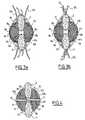
- FIGS. 2 a , 2 bwhich show a second embodiment of the invention in the rest state, seen from the front in longitudinal section ( FIG. 2 a ) and in profile ( FIG. 2 b );
- FIGS. 3 a and 3 bwhich show, seen in longitudinal section, the second embodiment of the invention at two stages of its placement
- FIG. 4which shows, seen in longitudinal section, a third embodiment of the invention after its placement.
- FIGS. 1 a and 1 bA first embodiment of the invention is shown in FIGS. 1 a and 1 b.
- the interspinous device 1is in the form of two pads 2 a , 2 b , each one having an internal face in the form of a substantially flat surface 3 a , 3 b intended to rest against the vertebrae when the wedge is put in place.
- each of these pads 2 a , 2 bis formed by a tape made of a material having some compressibility and low elasticity, such as polyester or an elastomer, folded over and sewn onto itself in order to form a stack of a general external shape that is, for example, hemispherical, semi-ovoid, or similar.
- the pads 2 a , 2 bfit tightly within the same tape-type ligament 4 made of a material comparable to that of the pads 2 a , 2 b , and the free parts of which connect, on the one hand, the upper parts and, on the other hand, the lower parts of the pads 3 a , 3 b , and which leaves the flat surfaces 3 a , 3 b free.
- This tape 4itself bears four ligaments 5 a , 5 b , 5 c , 5 d which are attached to it in the respective vicinities of the upper and lower parts of the pads 2 a , 2 b.
- the tape 4is fastened to the pads 2 a , 2 b and, in the rest state, when tensioned, its free parts allow a space of width “d” to be made between the internal surfaces 3 a , 3 b of the pads 2 a , 2 b.
- the interspinous device 1When the interspinous device 1 is put in place on the spinous processes 6 , 7 of two successive upper 8 and lower 9 vertebrae, it is as shown in FIG. 1 b.
- the device 1is inserted between the spinous processes 6 , 7 which are separated heightwise by a length substantially less than “d”. In this way, the lower part of the spinous apophysis 6 of the upper vertebra 8 and the upper part of the spinous apophysis 7 of the lower vertebra 9 tension the tape 4 .
- This tensioncompresses and brings together the pads 2 a , 2 b , the flat internal surfaces 3 a , 3 b of which come into contact with the sides of the spinous processes 6 , 7 and exert pressure forces on them in the direction of the arrows 10 , 10 ′, 10 ′′, 10 ′′′.
- the placement of the device 1is completed by ligaturing ligaments 5 a , 5 b at the upper part of the spinous apophysis 6 of the upper vertebra 8 and ligaments 5 c , 5 d at the lower part of the spinous apophysis 7 of the lower vertebra 9 .
- the dimensional and mechanical characteristics of the various elements of the device 1are calculated so that the pressures exerted by the pads 2 a , 2 b on the spinous processes 6 , 7 end up becoming enough to stop the coming-together thereof before causing trauma to the spinal nerves passing between the processes 6 , 7 , as would occur with a healthy functional unit.
- ligaments 5 a , 5 b , 5 c , 5 dalso play a role in impeding and interrupting the flexion movements of the spinal column, because of their possibilities of limited extension.
- each of the pads 2 a , 2 bmay be made in the form of a solid object, for example made of silicon lined with polyester, whose faces turned towards the spinous processes 6 , 7 may be flat (as in the previous example) or may each have a protuberance slightly penetrating into the inter-apophysis space so that the coming-together movements of the spinous processes 6 , 7 can be blocked more efficiently and reliably.
- each of the pads 11 a , 11 bhave their face 12 a , 12 b intended to be turned towards the spinous processes 6 , 7 which is of flat shape, it being understood that the said faces 12 a , 12 b could each have a protuberance as described above.
- Each of the pads 11 a , 11 bhas a series of perforations intended to allow the passage of the various ligaments making it possible to attach the pads 11 a , 11 b to the spinous processes 6 , 7 :
- the transverse perforations 15 a , 15 b ; 16 a , 16 bpass through the longitudinal perforations 13 a , 13 b ; however, this configuration is not essential.
- each wire ligament 18 , 19passes through the tape-type links 17 a , 17 b , but it must be understood that this arrangement is not essential, in particular if the transverse perforations ( 15 a , 15 b ; 16 a , 16 b ) do not pass through the longitudinal perforations 13 a , 13 b.
- the interspinous device provided by the pads 11 a , 11 bis implanted, as shown in FIGS. 3 a , 3 b.
- the pads 11 a , 11 bare placed against the spinous processes 6 , 7 of two successive vertebrae, with the upper wire ligament 18 passing under the apophysis 6 of the upper vertebra, and the lower wire ligament 19 passing over the apophysis 7 of the lower vertebra.
- the wire ligaments 18 , 19are then ligatured around their respective processes 6 , 7 , as shown in FIG. 3 a.
- the tape-type ligaments 17 a , 17 bare tied or fastened to each other at their two ends, as shown in FIG. 3 b.
- This operationfinishes putting the pads 11 a , 11 b in compression against the processes 6 , 7 , and makes it possible for them to function in a manner comparable to that of the device 1 shown in FIGS. 1 a , 1 b during flexions and extensions of the spinal column.
- this varianthas the advantage of not needing the interspinous ligaments to be sectioned for its implantation. The stability of the region concerned of the spinal column is thus improved.
- the pads 11 a , 11 bcould consist of tapes folded back on themselves, like the pads 2 a , 2 b. Under these conditions, the tape-type ligaments 17 a , 17 b may simply be fastened to the external faces 14 a , 14 b of the pads 11 a , 11 b without being housed in longitudinal perforations 13 a , 13 b in pads 11 a , 11 b. Moreover, this configuration could also be adopted with solid pads 11 a , 11 b.
- the interspinous deviceconsists of two pads 20 a , 20 b , each one of which has a protuberance 21 a , 21 b able to penetrate into the inter-apophysis space (as has been mentioned, such protuberances may be present on the pads of the other variants which have been described).
- These pads 20 a , 20 bhave longitudinal perforations 22 a , 22 b comparable to the longitudinal perforations 13 a , 13 b of the previous variant.
- Each of the latterencloses a wire- or tape-type ligament 23 , 24 , one end 25 , 26 of which is shaped into a loop.
- the ligaments 23 , 24are inserted into the pads 20 a , 20 b so that one 25 of the loops is placed on the lower face of its pad 20 a , and the other 26 on the upper face of its pad 20 b.
- the free end of each ligament 23 , 24is ligatured in the loop 25 , 26 of the other ligament 24 , 23 .
- the interspinous devicehas another feature which is only optional and which may, likewise, be transposed to the other variants of the invention.
- Each pad 20 a , 20 bhas a transverse perforation 27 , 28 placed substantially in the central region of the pad 20 a , 20 b.
- the perforationsare intended to face the interspinous space after the device has been put in place and to face each other.
- a pin 29made of a rigid or slightly deformable material, fitted at its ends with flanges 30 , 31 , each one bearing against the surface of a pad 20 a , 20 b turned outwards from the spinal column, passes through these transverse perforations 27 , 28 .
- This pin 29is inserted into the pads 20 a , 20 b before or after the interspinous device has been put in place.
- the prime function of this pin 29is to provide proper centring of the pads 20 a , 20 b with respect to one another. It also makes it possible to prevent a lateral expansion of the pads 20 a , 20 b during the extension movements of the spinal column. The stresses to which the pads 20 a , 20 b are subject are then transferred to their ends, and this increases the pressure forces exerted on the processes 6 , 7 .
- the pin 29may consist of a protuberance from one of the pads 20 a , 20 b , penetrating into a transverse perforation of the other pad where it is held by a flange secured to the pin after its insertion into the other pad.
Landscapes
- Health & Medical Sciences (AREA)
- Orthopedic Medicine & Surgery (AREA)
- Life Sciences & Earth Sciences (AREA)
- Neurology (AREA)
- Surgery (AREA)
- Heart & Thoracic Surgery (AREA)
- Engineering & Computer Science (AREA)
- Biomedical Technology (AREA)
- Nuclear Medicine, Radiotherapy & Molecular Imaging (AREA)
- Medical Informatics (AREA)
- Molecular Biology (AREA)
- Animal Behavior & Ethology (AREA)
- General Health & Medical Sciences (AREA)
- Public Health (AREA)
- Veterinary Medicine (AREA)
- Prostheses (AREA)
- Materials For Medical Uses (AREA)
- Surgical Instruments (AREA)
Abstract
Description
This application is a United States national phase application of co-pending international patent application number PCT/IB2004/000390, filed Feb. 17, 2004, which claims priority to French patent application number 03/02038, filed Feb. 19,2003 which priority is claimed.
The invention relates to the field of surgical implants intended to impede the coming-together of two vertebrae during movements of the spinal column.
When intervertebral discs have been subject to considerable wear or degeneration, they may become powerless to prevent excessive coming-together of two successive vertebrae during flexion (forward movement) or extension (backward movement) of the spinal column. Such coming-together may have the consequence of crushing the spinal nerves, which is very painful for the patient. In the most serious cases, this coming-together may continue until the vertebrae contact one another during extreme movements.
A first known method for solving this problem consists in fastening one of the vertebrae in question to the other, so as to keep a space between them which is permanently enough. This fastening may be carried out by means of various devices in the form of plates. However, it causes a significant loss of mobility for the patient, because it prohibits any flexion or extension of the spinal column in the region in question.
It is also known to ligature the spinous processes of the vertebrae in question by means of artificial ligaments. This makes it possible to retain freedom of movement in extension for the vertebrae while limiting the magnitude of the allowed flexions, to the extent of prohibiting contact between the front of the vertebrae. However, this does not prevent contact at the back of the vertebrae, although this region is where compression of the spinal nerves is most likely to occur.
It is also known to insert interspinous wedges between the spinous processes, as in document EP-A-0 392 124. These wedges are made of a rigid material such as PTFE, and thus prevent any contact between the spinous processes that they separate during extension of the spinal column. Preferably, they are held in place by artificial ligaments which pass through them and are wound around the spinous processes. By virtue of these ligaments, it is also possible to limit the magnitude of flexion movements of the spinal column in the region in question.
However, the fact of having a rigid element between the spinous processes leads to virtual removal of the extension movements of the spinal column at that point, or at least to a sudden interruption of such movements when the processes come into contact with the wedge.
It would be desirable to be able to use a device reproducing the normal behaviour of a vertebra-disc-vertebra stack (functional unit) more faithfully, where normally the action of blocking the movements of the spinal column only takes place gradually.
The aim of the invention is to provide a device meeting this requirement.
To this end, the subject of the invention is an interspinous device for impeding the movements of two successive vertebrae of the spinal column, characterized in that it comprises:
- two pads whose internal faces are intended to be pressed against the lateral faces of the spinous processes of the said vertebrae,
- and ligaments which connect the said pads to each other and to the said spinous processes, so that, during flexion and extension movements of the spinal column from its normal position, the pressures exerted against the lateral faces of the spinous processes by the said pads increase as the spinal column moves away from the said normal position.
Each of the said pads may have a protuberance intended to penetrate into the interspinous space.
Each of the said pads may consist of a tape folded over and sewn onto itself.
Each of the said pads may consist of a solid object.
The device may comprise a pin passing through transverse perforations in the said pads intended to be placed facing the interspinous space separating the two vertebrae, the said pin having flanges able to bear against the surfaces of the said pads, surfaces turned outwards from the spinal column.
The said ligaments may comprise:
- one ligament in the form of a tape fitting tightly around the pads and having free parts which, when tensioned, make a space having a width “d” greater than a distance separating the interspinous processes of the vertebrae,
- and four ligaments which are each attached to an upper part or to a lower part of a pad.
Each of the said pads may comprise:
- one longitudinal perforation connecting the upper part and the lower part of the pad,
- and two upper and lower transverse perforations connecting the internal face and the external face of the pad,
and the device may comprise two ligaments which are each inserted in one of the said longitudinal perforations, one ligament which is inserted in the upper transverse perforations of the said pads and one ligament which is inserted in the lower transverse perforations of the said pads.
In each pad, the said transverse perforations can then intersect the said longitudinal perforation, the ligaments inserted in the longitudinal perforations are in the form of a tape and the said ligaments inserted in the transverse perforations pass through the ligaments inserted in the longitudinal perforations.
Each pad may have a longitudinal perforation connecting the upper part and the lower part of the pad and a ligament inserted in the said longitudinal perforation, one end of which is free and the other end of which is shaped in a loop so that it can be ligatured with the free end of the ligament inserted in the longitudinal perforation of the other pad.
The subject of the invention is also a method for making a pad for such an interspinous device, characterized in that said pad is made by folding back and sewing on itself a tape made of a material such as polyester or an elastomer.
As will be understood, the invention consists in providing an interspinous device whose main elements consist of two elements pressed against the lateral faces of the spinous processes. They are made from a relatively flexible material having properties of compressibility and low elasticity. Polyesters and elastomers, or even some composites, may be used for this purpose. They may have a shape such that they slightly penetrate into the interspinous space at rest. They are held against the processes by artificial ligaments and are connected to each other in order to form an assembly:
- either by the same ligaments which hold them in place against the spinous processes;
- or by an envelope which confines them both at some distance from each other and on which the processes rest when the device is in place;
- or by a centring pin passing through both pads and passing through the interspinous space;
- or by several of these devices at the same time.
The elements are pressed against the spinous processes such that they transmit lateral pressures to them equally well during flexion movements as during extension movements of the spinal column, and also during rotational movements. These pressures increase as the spinal column moves away from its normal position, and end up being sufficiently high to stop the possibility of movement before excessive coming-together of the vertebrae takes place.
The invention will be better described with the help of the following appended figures:
A first embodiment of the invention is shown inFIGS. 1 aand1b.In the rest state (FIG. 1 a), the interspinous device1 is in the form of twopads flat surface 3a,3bintended to rest against the vertebrae when the wedge is put in place. In the example shown, each of thesepads pads pads pads 3a,3b, and which leaves theflat surfaces 3a,3bfree. This tape4 itself bears fourligaments pads pads internal surfaces 3a,3bof thepads
When the interspinous device1 is put in place on the spinous processes6,7 of two successive upper8 and lower9 vertebrae, it is as shown inFIG. 1 b.The device1 is inserted between the spinous processes6,7 which are separated heightwise by a length substantially less than “d”. In this way, the lower part of the spinous apophysis6 of theupper vertebra 8 and the upper part of the spinous apophysis7 of thelower vertebra 9 tension the tape4. This tension compresses and brings together thepads internal surfaces 3a,3bof which come into contact with the sides of the spinous processes6,7 and exert pressure forces on them in the direction of thearrows ligaments upper vertebra 8 andligaments lower vertebra 9.
In this way, when the spinal column operates in extension, that is to say when the patient bends backwards, and when the spinous processes6,7 tend to come close to each other, the tension exerted on the tape4 at its free parts tends to increase. The effect of this is to gradually increase the compression of thepads arrows pads
On the other hand, when the spinal column operates in flexion, that is to say when the patient bends forwards, and when the spinous processes6,7 tend to move away from each other, this has the effect of increasing the tension exerted on theligaments pads pads arrows ligaments
As a variant, each of thepads
The variant of the invention shown inFIGS. 2 a,2b,3a,3bhassuch pads pads face
Each of thepads pads
- one
longitudinal perforation face pad pad - and two
transverse perforations pad pad external faces pad
- one
In the example shown, thetransverse perforations longitudinal perforations
Ligaments pass through the various perforations as follows:
- each of the tape-
type ligaments longitudinal perforation pads - one and the same wire-type
upper ligament 18 passes through the uppertransverse perforation pads - and one and the same wire-type
lower ligament 19 passes through the lowertransverse perforation pads
- each of the tape-
In the example shown, eachwire ligament type links longitudinal perforations
The interspinous device provided by thepads FIGS. 3 a,3b.
First of all, thepads upper wire ligament 18 passing under the apophysis6 of the upper vertebra, and thelower wire ligament 19 passing over the apophysis7 of the lower vertebra. Thewire ligaments FIG. 3 a.
Secondly, the tape-type ligaments FIG. 3 b.This operation finishes putting thepads FIGS. 1 a,1bduring flexions and extensions of the spinal column.
Compared to the variant previously described and shown inFIGS. 1 a,1b, this variant has the advantage of not needing the interspinous ligaments to be sectioned for its implantation. The stability of the region concerned of the spinal column is thus improved.
Instead of consisting of solid objects as shown, thepads pads type ligaments pads longitudinal perforations pads solid pads
Another variant of the invention is shown inFIG. 4 . In this variant, the interspinous device consists of twopads 20a,20b, each one of which has aprotuberance pads 20a,20bhavelongitudinal perforations longitudinal perforations type ligament end ligaments pads 20a,20bso that one25 of the loops is placed on the lower face of itspad 20a, and the other26 on the upper face of its pad20b.When the interspinous device is put in place, the free end of eachligament loop other ligament
In this way, when the spinal column operates in flexion, the forces exerted by the processes6,7 on theligaments pads 20a,20bagainst the processes6,7, the movements of which are impeded as in the previous variants. When the spinal column operates in extension, thepads 20a,20btend to separate from each other under the effect of the forces exerted by the processes6,7 on theprotuberances ligaments pads 20a,20b, which tend to be pressed against the processes6,7 and therefore impede their coming together. Effects similar to those which have been described for the previous variants thus occur again.
In the example shown inFIG. 4 , the interspinous device has another feature which is only optional and which may, likewise, be transposed to the other variants of the invention. Eachpad 20a,20bhas atransverse perforation pad 20a,20b.The perforations are intended to face the interspinous space after the device has been put in place and to face each other. Apin 29 made of a rigid or slightly deformable material, fitted at its ends withflanges pad 20a,20bturned outwards from the spinal column, passes through thesetransverse perforations pin 29 is inserted into thepads 20a,20bbefore or after the interspinous device has been put in place. The prime function of thispin 29 is to provide proper centring of thepads 20a,20bwith respect to one another. It also makes it possible to prevent a lateral expansion of thepads 20a,20bduring the extension movements of the spinal column. The stresses to which thepads 20a,20bare subject are then transferred to their ends, and this increases the pressure forces exerted on the processes6,7.
As a variant, thepin 29 may consist of a protuberance from one of thepads 20a,20b, penetrating into a transverse perforation of the other pad where it is held by a flange secured to the pin after its insertion into the other pad.
It must be understood that the examples which have been described and shown are not limiting, and that, in particular, it would be possible to transpose to some other variants elements which have only been described for a single one of them if there is no obvious incompatibility which would prevent it.
Claims (4)
1. An interspinous device for impeding the movements of two successive vertebrae of the spinal column, comprising:
a first and second pad, each pad having external and internal faces, said internal faces configured to be pressed against the lateral faces of the spinous processes of the vertebrae,
a first, second, third, and fourth ligament which together connect the first and second pads to each other and are configured to attach the first and second pads to the spinous processes so that, during flexion and extension movements of the spinal column from its normal position, the pressures exerted against the lateral faces of the spinous processes by the first and second pads increase as the spinal column moves away from the normal position,
wherein the first and second pads each further comprise:
one longitudinal perforation connecting the upper part and the lower part of the pad;
an upper transverse perforation and a lower transverse perforation, each transverse perforation connecting the internal face and the external face of the pad;
wherein said first ligament is inserted in said longitudinal perforation of said first pad;
wherein said third ligament is inserted in the upper transverse perforation of said first and second pads;
wherein said third ligament is inserted in the upper transverse perforation of said first and second;
wherein said fourth ligament is inserted in the lower transverse perforation of said first and second pads;
wherein, in each pad, the upper and lower transverse perforations intersect the longitudinal perforation; and
the third and fourth ligaments pass through the first and second ligaments.
2. Device according toclaim 1 , wherein each of the pads has a protuberance configured to penetrate into the interspinous space.
3. Device according toclaim 1 , wherein each of the pads comprises of a tape folded over and sewn onto itself.
4. The device according to one ofclaims 1 and3 wherein each ligament inserted in the longitudinal perforation includes one end of which is free and the other end of which is shaped in a loop so that it can be ligatured with the free end of the ligament inserted in the longitudinal perforation of the other pad.
Applications Claiming Priority (3)
| Application Number | Priority Date | Filing Date | Title |
|---|---|---|---|
| FR0302038AFR2851154B1 (en) | 2003-02-19 | 2003-02-19 | INTER-SPINOUS DEVICE FOR BRAKING THE MOVEMENTS OF TWO SUCCESSIVE VERTEBRATES, AND METHOD FOR MANUFACTURING THE SAME THEREOF |
| FR03/02038 | 2003-02-19 | ||
| PCT/IB2004/000390WO2004073533A1 (en) | 2003-02-19 | 2004-02-17 | Interspinous device for impeding the movements of two successive vertebrae, and method for making a pad designed for it |
Publications (2)
| Publication Number | Publication Date |
|---|---|
| US20060217726A1 US20060217726A1 (en) | 2006-09-28 |
| US7520887B2true US7520887B2 (en) | 2009-04-21 |
Family
ID=32749699
Family Applications (1)
| Application Number | Title | Priority Date | Filing Date |
|---|---|---|---|
| US10/546,335Expired - Fee RelatedUS7520887B2 (en) | 2003-02-19 | 2004-02-17 | Interspinous device for impeding the movements of two successive vertebrae, and method for making a pad designed for it |
Country Status (9)
| Country | Link |
|---|---|
| US (1) | US7520887B2 (en) |
| EP (1) | EP1594412A1 (en) |
| JP (1) | JP4330617B2 (en) |
| KR (1) | KR101066714B1 (en) |
| CN (1) | CN100353919C (en) |
| AU (1) | AU2004212776B2 (en) |
| CA (1) | CA2516323C (en) |
| FR (1) | FR2851154B1 (en) |
| WO (1) | WO2004073533A1 (en) |
Cited By (55)
| Publication number | Priority date | Publication date | Assignee | Title |
|---|---|---|---|---|
| US20070225724A1 (en)* | 2006-03-24 | 2007-09-27 | Edmond Elizabeth W | Non-pedicle based interspinous spacer |
| US20070270836A1 (en)* | 2006-05-08 | 2007-11-22 | Sdgi Holdings, Inc. | Dynamic spinal stabilization members and methods |
| US20080009866A1 (en)* | 2004-03-09 | 2008-01-10 | Todd Alamin | Methods and systems for constraint of spinous processes with attachment |
| US20080108993A1 (en)* | 2006-10-19 | 2008-05-08 | Simpirica Spine, Inc. | Methods and systems for deploying spinous process constraints |
| US20080177264A1 (en)* | 2006-10-19 | 2008-07-24 | Simpirica Spine, Inc. | Methods and systems for laterally stabilized constraint of spinous processes |
| US20080262549A1 (en)* | 2006-10-19 | 2008-10-23 | Simpirica Spine, Inc. | Methods and systems for deploying spinous process constraints |
| US20080319487A1 (en)* | 2007-06-22 | 2008-12-25 | Simpirica Spine, Inc. | Methods and Devices for Controlled Flexion Restriction of Spinal Segments |
| US20090082820A1 (en)* | 2004-03-09 | 2009-03-26 | Louie Fielding | Spinal implant and method for restricting spinal flexion |
| US20090264929A1 (en)* | 2006-10-19 | 2009-10-22 | Simpirica Spine, Inc. | Structures and methods for constraining spinal processes with single connector |
| US20090264932A1 (en)* | 2006-10-19 | 2009-10-22 | Simpirica Spine, Inc. | Methods and systems for constraint of multiple spine segments |
| US20090306716A1 (en)* | 2006-12-08 | 2009-12-10 | Aesculap Ag | Implant and implant system |
| US20100004701A1 (en)* | 2008-06-06 | 2010-01-07 | Simpirica Spine, Inc. | Methods and apparatus for deploying spinous process constraints |
| US20100023060A1 (en)* | 2008-06-06 | 2010-01-28 | Simpirica Spine, Inc. | Methods and apparatus for locking a band |
| US20100036424A1 (en)* | 2007-06-22 | 2010-02-11 | Simpirica Spine, Inc. | Methods and systems for increasing the bending stiffness and constraining the spreading of a spinal segment |
| US20100234894A1 (en)* | 2009-03-10 | 2010-09-16 | Simpirica Spine, Inc. | Surgical tether apparatus and methods of use |
| US20100312343A1 (en)* | 2009-06-04 | 2010-12-09 | Linares Medical Devices, Llc | Tip support insert for application to left/right articular processes to minimize abrasion between vertebrae and to maintain proper angle/lift for reducing nerve compression |
| US20110172708A1 (en)* | 2007-06-22 | 2011-07-14 | Simpirica Spine, Inc. | Methods and systems for increasing the bending stiffness of a spinal segment with elongation limit |
| US20110190818A1 (en)* | 2010-02-01 | 2011-08-04 | Zimmer Spine | Intervertebral device |
| US20120136394A1 (en)* | 2008-12-17 | 2012-05-31 | Lanx, Inc. | Modular vertebral stabilizer |
| US8403960B2 (en) | 2005-09-19 | 2013-03-26 | Blackstone Medical, Inc. | Distance-keeping inter-process implant |
| US8562653B2 (en) | 2009-03-10 | 2013-10-22 | Simpirica Spine, Inc. | Surgical tether apparatus and methods of use |
| US8628574B2 (en) | 2004-10-20 | 2014-01-14 | Vertiflex, Inc. | Systems and methods for posterior dynamic stabilization of the spine |
| US8668719B2 (en) | 2009-03-30 | 2014-03-11 | Simpirica Spine, Inc. | Methods and apparatus for improving shear loading capacity of a spinal segment |
| US8740948B2 (en) | 2009-12-15 | 2014-06-03 | Vertiflex, Inc. | Spinal spacer for cervical and other vertebra, and associated systems and methods |
| US8845726B2 (en) | 2006-10-18 | 2014-09-30 | Vertiflex, Inc. | Dilator |
| US8864828B2 (en) | 2004-10-20 | 2014-10-21 | Vertiflex, Inc. | Interspinous spacer |
| EP2801328A1 (en) | 2013-05-06 | 2014-11-12 | Zimmer Spine | Intervertebral device |
| US8900271B2 (en) | 2004-10-20 | 2014-12-02 | The Board Of Trustees Of The Leland Stanford Junior University | Systems and methods for posterior dynamic stabilization of the spine |
| US9039742B2 (en) | 2004-10-20 | 2015-05-26 | The Board Of Trustees Of The Leland Stanford Junior University | Systems and methods for posterior dynamic stabilization of the spine |
| US9107706B2 (en) | 2009-03-10 | 2015-08-18 | Simpirica Spine, Inc. | Surgical tether apparatus and methods of use |
| US9119680B2 (en) | 2004-10-20 | 2015-09-01 | Vertiflex, Inc. | Interspinous spacer |
| US9125692B2 (en) | 2004-10-20 | 2015-09-08 | The Board Of Trustees Of The Leland Stanford Junior University | Systems and methods for posterior dynamic stabilization of the spine |
| US9149306B2 (en) | 2011-06-21 | 2015-10-06 | Seaspine, Inc. | Spinous process device |
| US9155570B2 (en) | 2004-10-20 | 2015-10-13 | Vertiflex, Inc. | Interspinous spacer |
| US9155572B2 (en) | 2004-10-20 | 2015-10-13 | Vertiflex, Inc. | Minimally invasive tooling for delivery of interspinous spacer |
| US9161783B2 (en) | 2004-10-20 | 2015-10-20 | Vertiflex, Inc. | Interspinous spacer |
| US9211146B2 (en) | 2004-10-20 | 2015-12-15 | The Board Of Trustees Of The Leland Stanford Junior University | Systems and methods for posterior dynamic stabilization of the spine |
| US9247968B2 (en) | 2007-01-11 | 2016-02-02 | Lanx, Inc. | Spinous process implants and associated methods |
| US9283005B2 (en) | 2004-10-20 | 2016-03-15 | Vertiflex, Inc. | Systems and methods for posterior dynamic stabilization of the spine |
| US9314279B2 (en) | 2004-10-20 | 2016-04-19 | The Board Of Trustees Of The Leland Stanford Junior University | Systems and methods for posterior dynamic stabilization of the spine |
| US9358122B2 (en) | 2011-01-07 | 2016-06-07 | K2M, Inc. | Interbody spacer |
| US9393055B2 (en) | 2004-10-20 | 2016-07-19 | Vertiflex, Inc. | Spacer insertion instrument |
| US9572603B2 (en) | 2004-10-20 | 2017-02-21 | Vertiflex, Inc. | Interspinous spacer |
| US9662150B1 (en) | 2007-02-26 | 2017-05-30 | Nuvasive, Inc. | Spinal stabilization system and methods of use |
| US9675303B2 (en) | 2013-03-15 | 2017-06-13 | Vertiflex, Inc. | Visualization systems, instruments and methods of using the same in spinal decompression procedures |
| US9743960B2 (en) | 2007-01-11 | 2017-08-29 | Zimmer Biomet Spine, Inc. | Interspinous implants and methods |
| US9770271B2 (en) | 2005-10-25 | 2017-09-26 | Zimmer Biomet Spine, Inc. | Spinal implants and methods |
| US9861400B2 (en) | 2007-01-11 | 2018-01-09 | Zimmer Biomet Spine, Inc. | Spinous process implants and associated methods |
| US10292738B2 (en) | 2004-10-20 | 2019-05-21 | The Board Of Trustees Of The Leland Stanford Junior University | Systems and methods for stabilizing the motion or adjusting the position of the spine |
| US10335207B2 (en) | 2015-12-29 | 2019-07-02 | Nuvasive, Inc. | Spinous process plate fixation assembly |
| US10524772B2 (en) | 2014-05-07 | 2020-01-07 | Vertiflex, Inc. | Spinal nerve decompression systems, dilation systems, and methods of using the same |
| US11812923B2 (en) | 2011-10-07 | 2023-11-14 | Alan Villavicencio | Spinal fixation device |
| US12102542B2 (en) | 2022-02-15 | 2024-10-01 | Boston Scientific Neuromodulation Corporation | Interspinous spacer and methods and systems utilizing the interspinous spacer |
| US12390340B2 (en) | 2023-03-15 | 2025-08-19 | Boston Scientific Neuromodulation Corporation | Interspinous spacer with a range of deployment positions and methods and systems |
| US12433646B2 (en) | 2023-02-21 | 2025-10-07 | Boston Scientific Neuromodulation Corporation | Interspinous spacer with actuator locking arrangements and methods and systems |
Families Citing this family (138)
| Publication number | Priority date | Publication date | Assignee | Title |
|---|---|---|---|---|
| US7201751B2 (en) | 1997-01-02 | 2007-04-10 | St. Francis Medical Technologies, Inc. | Supplemental spine fixation device |
| US7306628B2 (en) | 2002-10-29 | 2007-12-11 | St. Francis Medical Technologies | Interspinous process apparatus and method with a selectably expandable spacer |
| US20080027552A1 (en)* | 1997-01-02 | 2008-01-31 | Zucherman James F | Spine distraction implant and method |
| US6068630A (en) | 1997-01-02 | 2000-05-30 | St. Francis Medical Technologies, Inc. | Spine distraction implant |
| US20080039859A1 (en)* | 1997-01-02 | 2008-02-14 | Zucherman James F | Spine distraction implant and method |
| US20080086212A1 (en) | 1997-01-02 | 2008-04-10 | St. Francis Medical Technologies, Inc. | Spine distraction implant |
| US8128661B2 (en) | 1997-01-02 | 2012-03-06 | Kyphon Sarl | Interspinous process distraction system and method with positionable wing and method |
| US20080071378A1 (en)* | 1997-01-02 | 2008-03-20 | Zucherman James F | Spine distraction implant and method |
| US7959652B2 (en) | 2005-04-18 | 2011-06-14 | Kyphon Sarl | Interspinous process implant having deployable wings and method of implantation |
| US6579319B2 (en) | 2000-11-29 | 2003-06-17 | Medicinelodge, Inc. | Facet joint replacement |
| US20050080486A1 (en) | 2000-11-29 | 2005-04-14 | Fallin T. Wade | Facet joint replacement |
| US6565605B2 (en) | 2000-12-13 | 2003-05-20 | Medicinelodge, Inc. | Multiple facet joint replacement |
| US6419703B1 (en) | 2001-03-01 | 2002-07-16 | T. Wade Fallin | Prosthesis for the replacement of a posterior element of a vertebra |
| US7090698B2 (en) | 2001-03-02 | 2006-08-15 | Facet Solutions | Method and apparatus for spine joint replacement |
| FR2844179B1 (en)* | 2002-09-10 | 2004-12-03 | Jean Taylor | POSTERIOR VERTEBRAL SUPPORT KIT |
| US7833246B2 (en)* | 2002-10-29 | 2010-11-16 | Kyphon SÀRL | Interspinous process and sacrum implant and method |
| US7549999B2 (en) | 2003-05-22 | 2009-06-23 | Kyphon Sarl | Interspinous process distraction implant and method of implantation |
| US8147548B2 (en) | 2005-03-21 | 2012-04-03 | Kyphon Sarl | Interspinous process implant having a thread-shaped wing and method of implantation |
| US8070778B2 (en) | 2003-05-22 | 2011-12-06 | Kyphon Sarl | Interspinous process implant with slide-in distraction piece and method of implantation |
| US7909853B2 (en) | 2004-09-23 | 2011-03-22 | Kyphon Sarl | Interspinous process implant including a binder and method of implantation |
| US20080021468A1 (en) | 2002-10-29 | 2008-01-24 | Zucherman James F | Interspinous process implants and methods of use |
| US20060064165A1 (en)* | 2004-09-23 | 2006-03-23 | St. Francis Medical Technologies, Inc. | Interspinous process implant including a binder and method of implantation |
| US7931674B2 (en) | 2005-03-21 | 2011-04-26 | Kyphon Sarl | Interspinous process implant having deployable wing and method of implantation |
| US8048117B2 (en) | 2003-05-22 | 2011-11-01 | Kyphon Sarl | Interspinous process implant and method of implantation |
| US7335203B2 (en) | 2003-02-12 | 2008-02-26 | Kyphon Inc. | System and method for immobilizing adjacent spinous processes |
| US7588590B2 (en) | 2003-12-10 | 2009-09-15 | Facet Solutions, Inc | Spinal facet implant with spherical implant apposition surface and bone bed and methods of use |
| US8562649B2 (en) | 2004-02-17 | 2013-10-22 | Gmedelaware 2 Llc | System and method for multiple level facet joint arthroplasty and fusion |
| US7993373B2 (en) | 2005-02-22 | 2011-08-09 | Hoy Robert W | Polyaxial orthopedic fastening apparatus |
| US8333789B2 (en) | 2007-01-10 | 2012-12-18 | Gmedelaware 2 Llc | Facet joint replacement |
| US7585316B2 (en) | 2004-05-21 | 2009-09-08 | Warsaw Orthopedic, Inc. | Interspinous spacer |
| US7507242B2 (en) | 2004-06-02 | 2009-03-24 | Facet Solutions | Surgical measurement and resection framework |
| US8764801B2 (en) | 2005-03-28 | 2014-07-01 | Gmedelaware 2 Llc | Facet joint implant crosslinking apparatus and method |
| US7758581B2 (en) | 2005-03-28 | 2010-07-20 | Facet Solutions, Inc. | Polyaxial reaming apparatus and method |
| US8012209B2 (en) | 2004-09-23 | 2011-09-06 | Kyphon Sarl | Interspinous process implant including a binder, binder aligner and method of implantation |
| US8012207B2 (en) | 2004-10-20 | 2011-09-06 | Vertiflex, Inc. | Systems and methods for posterior dynamic stabilization of the spine |
| US8613747B2 (en) | 2004-10-20 | 2013-12-24 | Vertiflex, Inc. | Spacer insertion instrument |
| US8945183B2 (en) | 2004-10-20 | 2015-02-03 | Vertiflex, Inc. | Interspinous process spacer instrument system with deployment indicator |
| US8123782B2 (en) | 2004-10-20 | 2012-02-28 | Vertiflex, Inc. | Interspinous spacer |
| US8277488B2 (en) | 2004-10-20 | 2012-10-02 | Vertiflex, Inc. | Interspinous spacer |
| US20070276373A1 (en)* | 2005-02-17 | 2007-11-29 | Malandain Hugues F | Percutaneous Spinal Implants and Methods |
| US8096995B2 (en) | 2005-02-17 | 2012-01-17 | Kyphon Sarl | Percutaneous spinal implants and methods |
| US20070276493A1 (en) | 2005-02-17 | 2007-11-29 | Malandain Hugues F | Percutaneous spinal implants and methods |
| US8029567B2 (en) | 2005-02-17 | 2011-10-04 | Kyphon Sarl | Percutaneous spinal implants and methods |
| US7988709B2 (en) | 2005-02-17 | 2011-08-02 | Kyphon Sarl | Percutaneous spinal implants and methods |
| US7998208B2 (en) | 2005-02-17 | 2011-08-16 | Kyphon Sarl | Percutaneous spinal implants and methods |
| US8100943B2 (en) | 2005-02-17 | 2012-01-24 | Kyphon Sarl | Percutaneous spinal implants and methods |
| US8029549B2 (en) | 2005-02-17 | 2011-10-04 | Kyphon Sarl | Percutaneous spinal implants and methods |
| US8038698B2 (en) | 2005-02-17 | 2011-10-18 | Kphon Sarl | Percutaneous spinal implants and methods |
| US8097018B2 (en) | 2005-02-17 | 2012-01-17 | Kyphon Sarl | Percutaneous spinal implants and methods |
| US8096994B2 (en) | 2005-02-17 | 2012-01-17 | Kyphon Sarl | Percutaneous spinal implants and methods |
| US8092459B2 (en) | 2005-02-17 | 2012-01-10 | Kyphon Sarl | Percutaneous spinal implants and methods |
| US8157841B2 (en) | 2005-02-17 | 2012-04-17 | Kyphon Sarl | Percutaneous spinal implants and methods |
| US7998174B2 (en) | 2005-02-17 | 2011-08-16 | Kyphon Sarl | Percutaneous spinal implants and methods |
| US8057513B2 (en) | 2005-02-17 | 2011-11-15 | Kyphon Sarl | Percutaneous spinal implants and methods |
| US8007521B2 (en) | 2005-02-17 | 2011-08-30 | Kyphon Sarl | Percutaneous spinal implants and methods |
| US8034080B2 (en) | 2005-02-17 | 2011-10-11 | Kyphon Sarl | Percutaneous spinal implants and methods |
| US7993342B2 (en) | 2005-02-17 | 2011-08-09 | Kyphon Sarl | Percutaneous spinal implants and methods |
| US7927354B2 (en) | 2005-02-17 | 2011-04-19 | Kyphon Sarl | Percutaneous spinal implants and methods |
| US7604654B2 (en) | 2005-02-22 | 2009-10-20 | Stryker Spine | Apparatus and method for dynamic vertebral stabilization |
| JP2006253316A (en)* | 2005-03-09 | 2006-09-21 | Sony Corp | Solid-state imaging device |
| US7722647B1 (en) | 2005-03-14 | 2010-05-25 | Facet Solutions, Inc. | Apparatus and method for posterior vertebral stabilization |
| US20060241757A1 (en)* | 2005-03-31 | 2006-10-26 | Sdgi Holdings, Inc. | Intervertebral prosthetic device for spinal stabilization and method of manufacturing same |
| US8066742B2 (en) | 2005-03-31 | 2011-11-29 | Warsaw Orthopedic, Inc. | Intervertebral prosthetic device for spinal stabilization and method of implanting same |
| US7862590B2 (en) | 2005-04-08 | 2011-01-04 | Warsaw Orthopedic, Inc. | Interspinous process spacer |
| ES2556111T3 (en) | 2005-04-08 | 2016-01-13 | Paradigm Spine, Llc | Interspinous vertebral and lumbosacral stabilization devices |
| US7780709B2 (en)* | 2005-04-12 | 2010-08-24 | Warsaw Orthopedic, Inc. | Implants and methods for inter-transverse process dynamic stabilization of a spinal motion segment |
| US8034079B2 (en) | 2005-04-12 | 2011-10-11 | Warsaw Orthopedic, Inc. | Implants and methods for posterior dynamic stabilization of a spinal motion segment |
| US20060235386A1 (en)* | 2005-04-14 | 2006-10-19 | Sdgi Holdings, Inc. | Magnetic manipulation of a cable in blind approach |
| US7789898B2 (en)* | 2005-04-15 | 2010-09-07 | Warsaw Orthopedic, Inc. | Transverse process/laminar spacer |
| US7727233B2 (en)* | 2005-04-29 | 2010-06-01 | Warsaw Orthopedic, Inc. | Spinous process stabilization devices and methods |
| US7828830B2 (en) | 2005-05-12 | 2010-11-09 | Lanx, Inc. | Dynamic spinal stabilization |
| US20060271048A1 (en) | 2005-05-12 | 2006-11-30 | Jeffery Thramann | Pedicle screw based vertebral body stabilization apparatus |
| FR2887434B1 (en) | 2005-06-28 | 2008-03-28 | Jean Taylor | SURGICAL TREATMENT EQUIPMENT OF TWO VERTEBRATES |
| EP1942817B1 (en) | 2005-09-27 | 2014-05-07 | Paradigm Spine, LLC | Interspinous vertebral stabilization devices |
| US8357181B2 (en) | 2005-10-27 | 2013-01-22 | Warsaw Orthopedic, Inc. | Intervertebral prosthetic device for spinal stabilization and method of implanting same |
| US8137385B2 (en) | 2005-10-31 | 2012-03-20 | Stryker Spine | System and method for dynamic vertebral stabilization |
| US7862591B2 (en)* | 2005-11-10 | 2011-01-04 | Warsaw Orthopedic, Inc. | Intervertebral prosthetic device for spinal stabilization and method of implanting same |
| US20070173822A1 (en)* | 2006-01-13 | 2007-07-26 | Sdgi Holdings, Inc. | Use of a posterior dynamic stabilization system with an intradiscal device |
| US8083795B2 (en) | 2006-01-18 | 2011-12-27 | Warsaw Orthopedic, Inc. | Intervertebral prosthetic device for spinal stabilization and method of manufacturing same |
| US20070173823A1 (en) | 2006-01-18 | 2007-07-26 | Sdgi Holdings, Inc. | Intervertebral prosthetic device for spinal stabilization and method of implanting same |
| US7682376B2 (en) | 2006-01-27 | 2010-03-23 | Warsaw Orthopedic, Inc. | Interspinous devices and methods of use |
| US7691130B2 (en)* | 2006-01-27 | 2010-04-06 | Warsaw Orthopedic, Inc. | Spinal implants including a sensor and methods of use |
| US7837711B2 (en) | 2006-01-27 | 2010-11-23 | Warsaw Orthopedic, Inc. | Artificial spinous process for the sacrum and methods of use |
| US9011441B2 (en) | 2006-02-17 | 2015-04-21 | Paradigm Spine, L.L.C. | Method and system for performing interspinous space preparation for receiving an implant |
| US8262698B2 (en)* | 2006-03-16 | 2012-09-11 | Warsaw Orthopedic, Inc. | Expandable device for insertion between anatomical structures and a procedure utilizing same |
| US7985246B2 (en) | 2006-03-31 | 2011-07-26 | Warsaw Orthopedic, Inc. | Methods and instruments for delivering interspinous process spacers |
| FR2899788B1 (en)* | 2006-04-13 | 2008-07-04 | Jean Taylor | TREATMENT EQUIPMENT FOR VERTEBRATES, COMPRISING AN INTEREPINOUS IMPLANT |
| US8118844B2 (en) | 2006-04-24 | 2012-02-21 | Warsaw Orthopedic, Inc. | Expandable device for insertion between anatomical structures and a procedure utilizing same |
| DE102007018860B4 (en) | 2006-04-28 | 2023-01-05 | Paradigm Spine L.L.C. | Instrument system for use with an interspinous implant |
| US8105357B2 (en)* | 2006-04-28 | 2012-01-31 | Warsaw Orthopedic, Inc. | Interspinous process brace |
| US8252031B2 (en) | 2006-04-28 | 2012-08-28 | Warsaw Orthopedic, Inc. | Molding device for an expandable interspinous process implant |
| US20070270823A1 (en) | 2006-04-28 | 2007-11-22 | Sdgi Holdings, Inc. | Multi-chamber expandable interspinous process brace |
| US8048118B2 (en)* | 2006-04-28 | 2011-11-01 | Warsaw Orthopedic, Inc. | Adjustable interspinous process brace |
| US7846185B2 (en) | 2006-04-28 | 2010-12-07 | Warsaw Orthopedic, Inc. | Expandable interspinous process implant and method of installing same |
| US8348978B2 (en) | 2006-04-28 | 2013-01-08 | Warsaw Orthopedic, Inc. | Interosteotic implant |
| US8062337B2 (en) | 2006-05-04 | 2011-11-22 | Warsaw Orthopedic, Inc. | Expandable device for insertion between anatomical structures and a procedure utilizing same |
| US8147517B2 (en) | 2006-05-23 | 2012-04-03 | Warsaw Orthopedic, Inc. | Systems and methods for adjusting properties of a spinal implant |
| US20070276496A1 (en) | 2006-05-23 | 2007-11-29 | Sdgi Holdings, Inc. | Surgical spacer with shape control |
| US8048119B2 (en) | 2006-07-20 | 2011-11-01 | Warsaw Orthopedic, Inc. | Apparatus for insertion between anatomical structures and a procedure utilizing same |
| US20080086115A1 (en) | 2006-09-07 | 2008-04-10 | Warsaw Orthopedic, Inc. | Intercostal spacer device and method for use in correcting a spinal deformity |
| US8097019B2 (en) | 2006-10-24 | 2012-01-17 | Kyphon Sarl | Systems and methods for in situ assembly of an interspinous process distraction implant |
| US20080177298A1 (en)* | 2006-10-24 | 2008-07-24 | St. Francis Medical Technologies, Inc. | Tensioner Tool and Method for Implanting an Interspinous Process Implant Including a Binder |
| FR2908035B1 (en) | 2006-11-08 | 2009-05-01 | Jean Taylor | INTEREPINE IMPLANT |
| US8740941B2 (en) | 2006-11-10 | 2014-06-03 | Lanx, Inc. | Pedicle based spinal stabilization with adjacent vertebral body support |
| US7879104B2 (en) | 2006-11-15 | 2011-02-01 | Warsaw Orthopedic, Inc. | Spinal implant system |
| US20080114357A1 (en)* | 2006-11-15 | 2008-05-15 | Warsaw Orthopedic, Inc. | Inter-transverse process spacer device and method for use in correcting a spinal deformity |
| AR064013A1 (en) | 2006-11-30 | 2009-03-04 | Paradigm Spine Llc | VERTEBRAL, INTERLAMINAR, INTERESPINOUS STABILIZATION SYSTEM |
| US7955392B2 (en) | 2006-12-14 | 2011-06-07 | Warsaw Orthopedic, Inc. | Interspinous process devices and methods |
| CA2675037A1 (en) | 2007-01-10 | 2008-07-17 | Facet Solutions, Inc. | Taper-locking fixation system |
| US8840646B2 (en) | 2007-05-10 | 2014-09-23 | Warsaw Orthopedic, Inc. | Spinous process implants and methods |
| US20080281361A1 (en)* | 2007-05-10 | 2008-11-13 | Shannon Marlece Vittur | Posterior stabilization and spinous process systems and methods |
| US20080294200A1 (en)* | 2007-05-25 | 2008-11-27 | Andrew Kohm | Spinous process implants and methods of using the same |
| US20090005873A1 (en)* | 2007-06-29 | 2009-01-01 | Michael Andrew Slivka | Spinous Process Spacer Hammock |
| US8348976B2 (en)* | 2007-08-27 | 2013-01-08 | Kyphon Sarl | Spinous-process implants and methods of using the same |
| CA2781407A1 (en) | 2008-01-14 | 2009-07-23 | Michael P. Brenzel | Apparatus and methods for fracture repair |
| US20090198338A1 (en) | 2008-02-04 | 2009-08-06 | Phan Christopher U | Medical implants and methods |
| US8114136B2 (en) | 2008-03-18 | 2012-02-14 | Warsaw Orthopedic, Inc. | Implants and methods for inter-spinous process dynamic stabilization of a spinal motion segment |
| US8114131B2 (en) | 2008-11-05 | 2012-02-14 | Kyphon Sarl | Extension limiting devices and methods of use for the spine |
| EP2355727A4 (en)* | 2008-11-24 | 2013-01-09 | Simpirica Spine Inc | Methods and devices for restricting flexion and extension of a spinal segment |
| US8114135B2 (en) | 2009-01-16 | 2012-02-14 | Kyphon Sarl | Adjustable surgical cables and methods for treating spinal stenosis |
| US8372117B2 (en) | 2009-06-05 | 2013-02-12 | Kyphon Sarl | Multi-level interspinous implants and methods of use |
| US8157842B2 (en) | 2009-06-12 | 2012-04-17 | Kyphon Sarl | Interspinous implant and methods of use |
| US8771317B2 (en) | 2009-10-28 | 2014-07-08 | Warsaw Orthopedic, Inc. | Interspinous process implant and method of implantation |
| US8114132B2 (en) | 2010-01-13 | 2012-02-14 | Kyphon Sarl | Dynamic interspinous process device |
| US8317831B2 (en) | 2010-01-13 | 2012-11-27 | Kyphon Sarl | Interspinous process spacer diagnostic balloon catheter and methods of use |
| US8147526B2 (en) | 2010-02-26 | 2012-04-03 | Kyphon Sarl | Interspinous process spacer diagnostic parallel balloon catheter and methods of use |
| US8814908B2 (en) | 2010-07-26 | 2014-08-26 | Warsaw Orthopedic, Inc. | Injectable flexible interspinous process device system |
| US20120065683A1 (en)* | 2010-09-13 | 2012-03-15 | Fan-Ching Kuo | Interspinous process distraction device |
| US8496689B2 (en) | 2011-02-23 | 2013-07-30 | Farzad Massoudi | Spinal implant device with fusion cage and fixation plates and method of implanting |
| US8562650B2 (en) | 2011-03-01 | 2013-10-22 | Warsaw Orthopedic, Inc. | Percutaneous spinous process fusion plate assembly and method |
| US8425560B2 (en) | 2011-03-09 | 2013-04-23 | Farzad Massoudi | Spinal implant device with fixation plates and lag screws and method of implanting |
| US8591548B2 (en) | 2011-03-31 | 2013-11-26 | Warsaw Orthopedic, Inc. | Spinous process fusion plate assembly |
| US8591549B2 (en) | 2011-04-08 | 2013-11-26 | Warsaw Orthopedic, Inc. | Variable durometer lumbar-sacral implant |
| WO2013040456A1 (en) | 2011-09-14 | 2013-03-21 | Band-Lok, Llc | Tether clamp and implantation system |
| GB201220042D0 (en)* | 2012-11-07 | 2012-12-19 | Murray David W | Adjusting spinal curvature |
| EP3490474A4 (en) | 2016-07-26 | 2019-08-28 | Band-lok, LLC | ORTHOPEDIC IMPLANTS. |
| WO2019010252A2 (en) | 2017-07-04 | 2019-01-10 | Conventus Orthopaedics, Inc. | APPARATUS AND METHODS FOR TREATING BONES |
| AU2018299204A1 (en)* | 2017-07-12 | 2020-02-27 | Petridis, Harry MR | An orthosis |
Citations (19)
| Publication number | Priority date | Publication date | Assignee | Title |
|---|---|---|---|---|
| US1599564A (en)* | 1925-01-22 | 1926-09-14 | Del Roy F Fowler | Upholstery padding |
| US5496318A (en)* | 1993-01-08 | 1996-03-05 | Advanced Spine Fixation Systems, Inc. | Interspinous segmental spine fixation device |
| US5609634A (en)* | 1992-07-07 | 1997-03-11 | Voydeville; Gilles | Intervertebral prosthesis making possible rotatory stabilization and flexion/extension stabilization |
| US5836948A (en)* | 1997-01-02 | 1998-11-17 | Saint Francis Medical Technologies, Llc | Spine distraction implant and method |
| WO1999042051A1 (en)* | 1998-02-20 | 1999-08-26 | Jean Taylor | Interspinous prosthesis |
| US6099527A (en)* | 1998-04-30 | 2000-08-08 | Spinal Concepts, Inc. | Bone protector and method |
| US6187043B1 (en)* | 1987-12-22 | 2001-02-13 | Walter J. Ledergerber | Implantable prosthetic device |
| US20010016743A1 (en) | 1997-01-02 | 2001-08-23 | St. Francis Medical Technologies, Inc. | Spine distraction implant and method |
| FR2818530A1 (en) | 2000-12-22 | 2002-06-28 | Spine Next Sa | INTERVERTEBRAL IMPLANT WITH DEFORMABLE SHIM |
| WO2003015645A1 (en) | 2001-08-20 | 2003-02-27 | Synthes Ag Chur | Interspinal prosthesis |
| FR2844179A1 (en) | 2002-09-10 | 2004-03-12 | Jean Taylor | Posterior vertebral support assembly to correct for vertebral disk degeneration, includes two lateral transmission elements placed between two lateral compression lines and a spacer for maintaining height of inter-spinal zone |
| US6761720B1 (en)* | 1999-10-15 | 2004-07-13 | Spine Next | Intervertebral implant |
| US20050010298A1 (en)* | 2003-05-22 | 2005-01-13 | St. Francis Medical Technologies, Inc. | Cervical interspinous process distraction implant and method of implantation |
| US20050261768A1 (en)* | 2004-05-21 | 2005-11-24 | Trieu Hai H | Interspinous spacer |
| US20060085070A1 (en)* | 2004-10-20 | 2006-04-20 | Vertiflex, Inc. | Systems and methods for posterior dynamic stabilization of the spine |
| US20060089654A1 (en)* | 2004-10-25 | 2006-04-27 | Lins Robert E | Interspinous distraction devices and associated methods of insertion |
| US20060089718A1 (en)* | 2003-05-22 | 2006-04-27 | St. Francis Medical Technologies, Inc. | Interspinous process implant and method of implantation |
| US7048736B2 (en)* | 2002-05-17 | 2006-05-23 | Sdgi Holdings, Inc. | Device for fixation of spinous processes |
| US7238204B2 (en)* | 2000-07-12 | 2007-07-03 | Abbott Spine | Shock-absorbing intervertebral implant |
Family Cites Families (3)
| Publication number | Priority date | Publication date | Assignee | Title |
|---|---|---|---|---|
| FR2775283B1 (en) | 1998-02-24 | 2000-03-24 | Inst Francais Du Petrole | PROCESS FOR SELECTIVELY INCREASING THE ISOBUTANE CONTENT OF A CUT OF OLEFINS WITH 4 CARBON ATOMS FROM CRACKING, FOR ITS USE IN ALKYLATION |
| CN2378009Y (en)* | 1999-05-21 | 2000-05-17 | 黄令坚 | Multi-jaw forceps holder type spine fixer |
| CN2401157Y (en)* | 1999-12-09 | 2000-10-18 | 中国人民解放军第二军医大学 | Arcus posterior atlantis fixator and special forceps thereof |
- 2003
- 2003-02-19FRFR0302038Apatent/FR2851154B1/ennot_activeExpired - Fee Related
- 2004
- 2004-02-17CACA002516323Apatent/CA2516323C/ennot_activeExpired - Fee Related
- 2004-02-17JPJP2006502436Apatent/JP4330617B2/ennot_activeExpired - Fee Related
- 2004-02-17AUAU2004212776Apatent/AU2004212776B2/ennot_activeCeased
- 2004-02-17WOPCT/IB2004/000390patent/WO2004073533A1/enactiveSearch and Examination
- 2004-02-17KRKR1020057015201Apatent/KR101066714B1/ennot_activeExpired - Fee Related
- 2004-02-17EPEP04711670Apatent/EP1594412A1/ennot_activeWithdrawn
- 2004-02-17USUS10/546,335patent/US7520887B2/ennot_activeExpired - Fee Related
- 2004-02-17CNCNB2004800046902Apatent/CN100353919C/ennot_activeExpired - Fee Related
Patent Citations (22)
| Publication number | Priority date | Publication date | Assignee | Title |
|---|---|---|---|---|
| US1599564A (en)* | 1925-01-22 | 1926-09-14 | Del Roy F Fowler | Upholstery padding |
| US6187043B1 (en)* | 1987-12-22 | 2001-02-13 | Walter J. Ledergerber | Implantable prosthetic device |
| US5609634A (en)* | 1992-07-07 | 1997-03-11 | Voydeville; Gilles | Intervertebral prosthesis making possible rotatory stabilization and flexion/extension stabilization |
| US5496318A (en)* | 1993-01-08 | 1996-03-05 | Advanced Spine Fixation Systems, Inc. | Interspinous segmental spine fixation device |
| US5836948A (en)* | 1997-01-02 | 1998-11-17 | Saint Francis Medical Technologies, Llc | Spine distraction implant and method |
| US20010016743A1 (en) | 1997-01-02 | 2001-08-23 | St. Francis Medical Technologies, Inc. | Spine distraction implant and method |
| WO1999042051A1 (en)* | 1998-02-20 | 1999-08-26 | Jean Taylor | Interspinous prosthesis |
| FR2775183A1 (en) | 1998-02-20 | 1999-08-27 | Jean Taylor | INTER-SPINOUS PROSTHESIS |
| US6626944B1 (en)* | 1998-02-20 | 2003-09-30 | Jean Taylor | Interspinous prosthesis |
| US6099527A (en)* | 1998-04-30 | 2000-08-08 | Spinal Concepts, Inc. | Bone protector and method |
| US6761720B1 (en)* | 1999-10-15 | 2004-07-13 | Spine Next | Intervertebral implant |
| US7238204B2 (en)* | 2000-07-12 | 2007-07-03 | Abbott Spine | Shock-absorbing intervertebral implant |
| US6946000B2 (en)* | 2000-12-22 | 2005-09-20 | Spine Next | Intervertebral implant with deformable wedge |
| FR2818530A1 (en) | 2000-12-22 | 2002-06-28 | Spine Next Sa | INTERVERTEBRAL IMPLANT WITH DEFORMABLE SHIM |
| WO2003015645A1 (en) | 2001-08-20 | 2003-02-27 | Synthes Ag Chur | Interspinal prosthesis |
| US7048736B2 (en)* | 2002-05-17 | 2006-05-23 | Sdgi Holdings, Inc. | Device for fixation of spinous processes |
| FR2844179A1 (en) | 2002-09-10 | 2004-03-12 | Jean Taylor | Posterior vertebral support assembly to correct for vertebral disk degeneration, includes two lateral transmission elements placed between two lateral compression lines and a spacer for maintaining height of inter-spinal zone |
| US20050010298A1 (en)* | 2003-05-22 | 2005-01-13 | St. Francis Medical Technologies, Inc. | Cervical interspinous process distraction implant and method of implantation |
| US20060089718A1 (en)* | 2003-05-22 | 2006-04-27 | St. Francis Medical Technologies, Inc. | Interspinous process implant and method of implantation |
| US20050261768A1 (en)* | 2004-05-21 | 2005-11-24 | Trieu Hai H | Interspinous spacer |
| US20060085070A1 (en)* | 2004-10-20 | 2006-04-20 | Vertiflex, Inc. | Systems and methods for posterior dynamic stabilization of the spine |
| US20060089654A1 (en)* | 2004-10-25 | 2006-04-27 | Lins Robert E | Interspinous distraction devices and associated methods of insertion |
Non-Patent Citations (1)
| Title |
|---|
| Patent Cooperation Treaty, "PCT International Search Report," International Application No. PCT/IB2004/000390, Jun. 4, 2004, 7 pages. |
Cited By (117)
| Publication number | Priority date | Publication date | Assignee | Title |
|---|---|---|---|---|
| US8105363B2 (en) | 2004-03-09 | 2012-01-31 | The Board Of Trustees Of The Leland Stanford Junior University | Spinal implant and method for restricting spinal flexion |
| US10080589B2 (en) | 2004-03-09 | 2018-09-25 | The Board Of Trustees Of The Leland Stanford Junior University | Methods and systems for constraint of spinous processes with attachment |
| US20080009866A1 (en)* | 2004-03-09 | 2008-01-10 | Todd Alamin | Methods and systems for constraint of spinous processes with attachment |
| US9149304B2 (en) | 2004-03-09 | 2015-10-06 | The Board Of Trustees Of The Leland Sanford Junior University | Methods and systems for constraint of spinous processes with attachment |
| US8523904B2 (en) | 2004-03-09 | 2013-09-03 | The Board Of Trustees Of The Leland Stanford Junior University | Methods and systems for constraint of spinous processes with attachment |
| US8486110B2 (en) | 2004-03-09 | 2013-07-16 | The Board Of Trustees Of The Leland Stanford Junior University | Spinal implant and method for restricting spinal flexion |
| US8216275B2 (en) | 2004-03-09 | 2012-07-10 | The Board Of Trustees Of The Leland Stanford Junior University | Spinal implant and method for restricting spinal flexion |
| US20090082820A1 (en)* | 2004-03-09 | 2009-03-26 | Louie Fielding | Spinal implant and method for restricting spinal flexion |
| US20090198282A1 (en)* | 2004-03-09 | 2009-08-06 | Louis Fielding | Spinal implant and method for restricting spinal flexion |
| US10166047B2 (en) | 2004-10-20 | 2019-01-01 | Vertiflex, Inc. | Interspinous spacer |
| US9119680B2 (en) | 2004-10-20 | 2015-09-01 | Vertiflex, Inc. | Interspinous spacer |
| US11076893B2 (en) | 2004-10-20 | 2021-08-03 | Vertiflex, Inc. | Methods for treating a patient's spine |
| US10835295B2 (en) | 2004-10-20 | 2020-11-17 | Vertiflex, Inc. | Interspinous spacer |
| US10835297B2 (en) | 2004-10-20 | 2020-11-17 | Vertiflex, Inc. | Interspinous spacer |
| US10709481B2 (en) | 2004-10-20 | 2020-07-14 | The Board Of Trustees Of The Leland Stanford Junior University | Systems and methods for posterior dynamic stabilization of the spine |
| US8900271B2 (en) | 2004-10-20 | 2014-12-02 | The Board Of Trustees Of The Leland Stanford Junior University | Systems and methods for posterior dynamic stabilization of the spine |
| US10610267B2 (en) | 2004-10-20 | 2020-04-07 | Vertiflex, Inc. | Spacer insertion instrument |
| US10292738B2 (en) | 2004-10-20 | 2019-05-21 | The Board Of Trustees Of The Leland Stanford Junior University | Systems and methods for stabilizing the motion or adjusting the position of the spine |
| US10278744B2 (en) | 2004-10-20 | 2019-05-07 | The Board Of Trustees Of The Leland Stanford Junior University | Systems and methods for posterior dynamic stabilization of the spine |
| US10258389B2 (en) | 2004-10-20 | 2019-04-16 | The Board Of Trustees Of The Leland Stanford Junior University | Systems and methods for posterior dynamic stabilization of the spine |
| US10080587B2 (en) | 2004-10-20 | 2018-09-25 | Vertiflex, Inc. | Methods for treating a patient's spine |
| US10058358B2 (en) | 2004-10-20 | 2018-08-28 | The Board Of Trustees Of The Leland Stanford Junior University | Systems and methods for posterior dynamic stabilization of the spine |
| US10039576B2 (en) | 2004-10-20 | 2018-08-07 | The Board Of Trustees Of The Leland Stanford Junior University | Systems and methods for posterior dynamic stabilization of the spine |
| US9956011B2 (en) | 2004-10-20 | 2018-05-01 | Vertiflex, Inc. | Interspinous spacer |
| US9877749B2 (en) | 2004-10-20 | 2018-01-30 | The Board Of Trustees Of The Leland Stanford Junior University | Systems and methods for posterior dynamic stabilization of the spine |
| US9861398B2 (en) | 2004-10-20 | 2018-01-09 | Vertiflex, Inc. | Interspinous spacer |
| US9039742B2 (en) | 2004-10-20 | 2015-05-26 | The Board Of Trustees Of The Leland Stanford Junior University | Systems and methods for posterior dynamic stabilization of the spine |
| US9572603B2 (en) | 2004-10-20 | 2017-02-21 | Vertiflex, Inc. | Interspinous spacer |
| US9532812B2 (en) | 2004-10-20 | 2017-01-03 | Vertiflex, Inc. | Interspinous spacer |
| US9283005B2 (en) | 2004-10-20 | 2016-03-15 | Vertiflex, Inc. | Systems and methods for posterior dynamic stabilization of the spine |
| US9211146B2 (en) | 2004-10-20 | 2015-12-15 | The Board Of Trustees Of The Leland Stanford Junior University | Systems and methods for posterior dynamic stabilization of the spine |
| US9445843B2 (en) | 2004-10-20 | 2016-09-20 | The Board Of Trustees Of The Leland Stanford Junior University | Systems and methods for posterior dynamic stabilization of the spine |
| US9393055B2 (en) | 2004-10-20 | 2016-07-19 | Vertiflex, Inc. | Spacer insertion instrument |
| US9314279B2 (en) | 2004-10-20 | 2016-04-19 | The Board Of Trustees Of The Leland Stanford Junior University | Systems and methods for posterior dynamic stabilization of the spine |
| US8864828B2 (en) | 2004-10-20 | 2014-10-21 | Vertiflex, Inc. | Interspinous spacer |
| US9161783B2 (en) | 2004-10-20 | 2015-10-20 | Vertiflex, Inc. | Interspinous spacer |
| US9155572B2 (en) | 2004-10-20 | 2015-10-13 | Vertiflex, Inc. | Minimally invasive tooling for delivery of interspinous spacer |
| US9155570B2 (en) | 2004-10-20 | 2015-10-13 | Vertiflex, Inc. | Interspinous spacer |
| US9125692B2 (en) | 2004-10-20 | 2015-09-08 | The Board Of Trustees Of The Leland Stanford Junior University | Systems and methods for posterior dynamic stabilization of the spine |
| US8628574B2 (en) | 2004-10-20 | 2014-01-14 | Vertiflex, Inc. | Systems and methods for posterior dynamic stabilization of the spine |
| US10653456B2 (en) | 2005-02-04 | 2020-05-19 | Vertiflex, Inc. | Interspinous spacer |
| US8403960B2 (en) | 2005-09-19 | 2013-03-26 | Blackstone Medical, Inc. | Distance-keeping inter-process implant |
| US8979899B2 (en) | 2005-09-19 | 2015-03-17 | Blackstone Medical, Inc. | Distance-keeping inter-process implant |
| US9770271B2 (en) | 2005-10-25 | 2017-09-26 | Zimmer Biomet Spine, Inc. | Spinal implants and methods |
| US8361116B2 (en)* | 2006-03-24 | 2013-01-29 | U.S. Spine, Inc. | Non-pedicle based interspinous spacer |
| US20070225724A1 (en)* | 2006-03-24 | 2007-09-27 | Edmond Elizabeth W | Non-pedicle based interspinous spacer |
| US8906066B2 (en) | 2006-03-24 | 2014-12-09 | Us Spine, Inc. | Non-pedicle based interspinous spacer methods |
| US8012179B2 (en)* | 2006-05-08 | 2011-09-06 | Warsaw Orthopedic, Inc. | Dynamic spinal stabilization members and methods |
| US20070270836A1 (en)* | 2006-05-08 | 2007-11-22 | Sdgi Holdings, Inc. | Dynamic spinal stabilization members and methods |
| US11986221B2 (en) | 2006-10-18 | 2024-05-21 | Vertiflex, Inc. | Interspinous spacer |
| US12035946B2 (en) | 2006-10-18 | 2024-07-16 | Boston Scientific Neuromodulation Corporation | Interspinous spacer |
| US9566086B2 (en) | 2006-10-18 | 2017-02-14 | VeriFlex, Inc. | Dilator |
| US11229461B2 (en) | 2006-10-18 | 2022-01-25 | Vertiflex, Inc. | Interspinous spacer |
| US11013539B2 (en) | 2006-10-18 | 2021-05-25 | Vertiflex, Inc. | Methods for treating a patient's spine |
| US10588663B2 (en) | 2006-10-18 | 2020-03-17 | Vertiflex, Inc. | Dilator |
| US12035947B2 (en) | 2006-10-18 | 2024-07-16 | Boston Scientific Neuromodulation Corporation | Devices and methods for treating a patient's spine |
| US8845726B2 (en) | 2006-10-18 | 2014-09-30 | Vertiflex, Inc. | Dilator |
| US12226130B2 (en) | 2006-10-18 | 2025-02-18 | Vertiflex, Inc. | Interspinous spacer |
| US8162982B2 (en) | 2006-10-19 | 2012-04-24 | Simpirica Spine, Inc. | Methods and systems for constraint of multiple spine segments |
| US20130253584A1 (en)* | 2006-10-19 | 2013-09-26 | Simpirica Spine, Inc. | Methods and systems for laterally stabilized constraint of spinous processes |
| US8790372B2 (en) | 2006-10-19 | 2014-07-29 | Simpirica Spine, Inc. | Methods and systems for constraint of multiple spine segments |
| US20080262549A1 (en)* | 2006-10-19 | 2008-10-23 | Simpirica Spine, Inc. | Methods and systems for deploying spinous process constraints |
| US20090264929A1 (en)* | 2006-10-19 | 2009-10-22 | Simpirica Spine, Inc. | Structures and methods for constraining spinal processes with single connector |
| US20090264932A1 (en)* | 2006-10-19 | 2009-10-22 | Simpirica Spine, Inc. | Methods and systems for constraint of multiple spine segments |
| US9295499B2 (en)* | 2006-10-19 | 2016-03-29 | Empirical Spine, Inc. | Methods and systems for laterally stabilized constraint of spinous processes |
| US8454660B2 (en) | 2006-10-19 | 2013-06-04 | Simpirica Spine, Inc. | Methods and systems for laterally stabilized constraint of spinous processes |
| US20080177264A1 (en)* | 2006-10-19 | 2008-07-24 | Simpirica Spine, Inc. | Methods and systems for laterally stabilized constraint of spinous processes |
| US20080108993A1 (en)* | 2006-10-19 | 2008-05-08 | Simpirica Spine, Inc. | Methods and systems for deploying spinous process constraints |
| US8187307B2 (en) | 2006-10-19 | 2012-05-29 | Simpirica Spine, Inc. | Structures and methods for constraining spinal processes with single connector |
| US8029541B2 (en)* | 2006-10-19 | 2011-10-04 | Simpirica Spine, Inc. | Methods and systems for laterally stabilized constraint of spinous processes |
| US8313513B2 (en) | 2006-12-08 | 2012-11-20 | Aesculap Ag | Implant and implant system |
| US20090306716A1 (en)* | 2006-12-08 | 2009-12-10 | Aesculap Ag | Implant and implant system |
| US9247968B2 (en) | 2007-01-11 | 2016-02-02 | Lanx, Inc. | Spinous process implants and associated methods |
| US9743960B2 (en) | 2007-01-11 | 2017-08-29 | Zimmer Biomet Spine, Inc. | Interspinous implants and methods |
| US9861400B2 (en) | 2007-01-11 | 2018-01-09 | Zimmer Biomet Spine, Inc. | Spinous process implants and associated methods |
| US9724136B2 (en) | 2007-01-11 | 2017-08-08 | Zimmer Biomet Spine, Inc. | Spinous process implants and associated methods |
| US9662150B1 (en) | 2007-02-26 | 2017-05-30 | Nuvasive, Inc. | Spinal stabilization system and methods of use |
| US10080590B2 (en) | 2007-02-26 | 2018-09-25 | Nuvasive, Inc. | Spinal stabilization system and methods of use |
| US20080319487A1 (en)* | 2007-06-22 | 2008-12-25 | Simpirica Spine, Inc. | Methods and Devices for Controlled Flexion Restriction of Spinal Segments |
| US20100036424A1 (en)* | 2007-06-22 | 2010-02-11 | Simpirica Spine, Inc. | Methods and systems for increasing the bending stiffness and constraining the spreading of a spinal segment |
| US20110172708A1 (en)* | 2007-06-22 | 2011-07-14 | Simpirica Spine, Inc. | Methods and systems for increasing the bending stiffness of a spinal segment with elongation limit |
| US8403961B2 (en) | 2007-06-22 | 2013-03-26 | Simpirica Spine, Inc. | Methods and devices for controlled flexion restriction of spinal segments |
| US8403964B2 (en) | 2007-06-22 | 2013-03-26 | Simpirica Spine, Inc. | Methods and systems for increasing the bending stiffness and constraining the spreading of a spinal segment |
| US20230085446A1 (en)* | 2007-06-22 | 2023-03-16 | Empirical Spine, Inc, | Methods and systems for increasing the bending stiffness of a spinal segment with elongation limit |
| US20100023060A1 (en)* | 2008-06-06 | 2010-01-28 | Simpirica Spine, Inc. | Methods and apparatus for locking a band |
| US8187305B2 (en) | 2008-06-06 | 2012-05-29 | Simpirica Spine, Inc. | Methods and apparatus for deploying spinous process constraints |
| US8308771B2 (en) | 2008-06-06 | 2012-11-13 | Simpirica Spine, Inc. | Methods and apparatus for locking a band |
| US20100004701A1 (en)* | 2008-06-06 | 2010-01-07 | Simpirica Spine, Inc. | Methods and apparatus for deploying spinous process constraints |
| US20120136394A1 (en)* | 2008-12-17 | 2012-05-31 | Lanx, Inc. | Modular vertebral stabilizer |
| US9339303B2 (en)* | 2008-12-17 | 2016-05-17 | Lanx, S.R.L. | Modular vertebral stabilizer |
| US20140364914A1 (en)* | 2008-12-17 | 2014-12-11 | Lanx, S.R.L. | Modular Vertebral Stabilizer |
| US9107706B2 (en) | 2009-03-10 | 2015-08-18 | Simpirica Spine, Inc. | Surgical tether apparatus and methods of use |
| US10314623B2 (en) | 2009-03-10 | 2019-06-11 | Empirical Spine, Inc. | Surgical tether apparatus and methods of use |
| US8529606B2 (en) | 2009-03-10 | 2013-09-10 | Simpirica Spine, Inc. | Surgical tether apparatus and methods of use |
| US8562653B2 (en) | 2009-03-10 | 2013-10-22 | Simpirica Spine, Inc. | Surgical tether apparatus and methods of use |
| US20100234894A1 (en)* | 2009-03-10 | 2010-09-16 | Simpirica Spine, Inc. | Surgical tether apparatus and methods of use |
| US12167874B2 (en) | 2009-03-10 | 2024-12-17 | Empirical Spine, Inc. | Surgical tether apparatus and methods of use |
| US8668719B2 (en) | 2009-03-30 | 2014-03-11 | Simpirica Spine, Inc. | Methods and apparatus for improving shear loading capacity of a spinal segment |
| US20100312343A1 (en)* | 2009-06-04 | 2010-12-09 | Linares Medical Devices, Llc | Tip support insert for application to left/right articular processes to minimize abrasion between vertebrae and to maintain proper angle/lift for reducing nerve compression |
| US9186186B2 (en) | 2009-12-15 | 2015-11-17 | Vertiflex, Inc. | Spinal spacer for cervical and other vertebra, and associated systems and methods |
| US8740948B2 (en) | 2009-12-15 | 2014-06-03 | Vertiflex, Inc. | Spinal spacer for cervical and other vertebra, and associated systems and methods |
| US20110190818A1 (en)* | 2010-02-01 | 2011-08-04 | Zimmer Spine | Intervertebral device |
| US9358122B2 (en) | 2011-01-07 | 2016-06-07 | K2M, Inc. | Interbody spacer |
| US9149306B2 (en) | 2011-06-21 | 2015-10-06 | Seaspine, Inc. | Spinous process device |
| US11812923B2 (en) | 2011-10-07 | 2023-11-14 | Alan Villavicencio | Spinal fixation device |
| US9675303B2 (en) | 2013-03-15 | 2017-06-13 | Vertiflex, Inc. | Visualization systems, instruments and methods of using the same in spinal decompression procedures |
| WO2014180844A1 (en) | 2013-05-06 | 2014-11-13 | Zimmer Spine | Intervertebral device |
| EP2801328A1 (en) | 2013-05-06 | 2014-11-12 | Zimmer Spine | Intervertebral device |
| US11357489B2 (en) | 2014-05-07 | 2022-06-14 | Vertiflex, Inc. | Spinal nerve decompression systems, dilation systems, and methods of using the same |
| US12035884B2 (en) | 2014-05-07 | 2024-07-16 | Boston Scientific Neuromodulation Corporation | Spinal nerve decompression systems, dilation systems, and methods of using the same |
| US10524772B2 (en) | 2014-05-07 | 2020-01-07 | Vertiflex, Inc. | Spinal nerve decompression systems, dilation systems, and methods of using the same |
| US11382670B2 (en) | 2015-12-29 | 2022-07-12 | Nuvasive, Inc. | Spinous process plate fixation assembly |
| US12137948B2 (en) | 2015-12-29 | 2024-11-12 | Nuvasive, Inc. | Spinous process plate fixation assembly |
| US10335207B2 (en) | 2015-12-29 | 2019-07-02 | Nuvasive, Inc. | Spinous process plate fixation assembly |
| US12102542B2 (en) | 2022-02-15 | 2024-10-01 | Boston Scientific Neuromodulation Corporation | Interspinous spacer and methods and systems utilizing the interspinous spacer |
| US12433646B2 (en) | 2023-02-21 | 2025-10-07 | Boston Scientific Neuromodulation Corporation | Interspinous spacer with actuator locking arrangements and methods and systems |
| US12390340B2 (en) | 2023-03-15 | 2025-08-19 | Boston Scientific Neuromodulation Corporation | Interspinous spacer with a range of deployment positions and methods and systems |
Also Published As
| Publication number | Publication date |
|---|---|
| CN1774213A (en) | 2006-05-17 |
| CN100353919C (en) | 2007-12-12 |
| EP1594412A1 (en) | 2005-11-16 |
| JP4330617B2 (en) | 2009-09-16 |
| AU2004212776A1 (en) | 2004-09-02 |
| JP2006517824A (en) | 2006-08-03 |
| KR101066714B1 (en) | 2011-09-21 |
| KR20050103497A (en) | 2005-10-31 |
| FR2851154A1 (en) | 2004-08-20 |
| AU2004212776B2 (en) | 2010-06-17 |
| WO2004073533A1 (en) | 2004-09-02 |
| FR2851154B1 (en) | 2006-07-07 |
| CA2516323A1 (en) | 2004-09-02 |
| CA2516323C (en) | 2010-01-19 |
| US20060217726A1 (en) | 2006-09-28 |
Similar Documents
| Publication | Publication Date | Title |
|---|---|---|
| US7520887B2 (en) | Interspinous device for impeding the movements of two successive vertebrae, and method for making a pad designed for it | |
| US7704281B2 (en) | Intervertebral implant for the lumbosacral articulation | |
| US8162982B2 (en) | Methods and systems for constraint of multiple spine segments | |
| JP5555711B2 (en) | Methods and devices for limiting spinal segment flexion and extension | |
| US20160256201A1 (en) | Methods and systems for constraint of spinous processes with attachment | |
| EP2083701A2 (en) | Methods and systems for constraint of multiple spine segments | |
| US20060241613A1 (en) | Implants and methods for inter-transverse process dynamic stabilization of a spinal motion segment | |
| US20140018808A1 (en) | Hybrid medical device implant with migration management | |
| US20160008038A1 (en) | Methods and systems for constraint of multiple spine segments | |
| WO2006136938A1 (en) | Interspinous stabilisation device | |
| CN112789001A (en) | Device for cerclage of fractured bone and system for cerclage of fractured bone comprising same | |
| KR100701574B1 (en) | Intervertebral insert | |
| KR100620115B1 (en) | Intervertebral insert | |
| US20220338905A1 (en) | Methods and systems for constraint of spinous processes with attachment | |
| CN111110336B (en) | Interspinous process gasket device |
Legal Events
| Date | Code | Title | Description |
|---|---|---|---|
| AS | Assignment | Owner name:SDGI HOLDINGS, INC., DELAWARE Free format text:ASSIGNMENT OF ASSIGNORS INTEREST;ASSIGNORS:MAXY, PHILIPPE;GOURNAY, JOSE;REEL/FRAME:020625/0556 Effective date:20050802 | |
| AS | Assignment | Owner name:WARSAW ORTHOPEDIC, INC., INDIANA Free format text:MERGER;ASSIGNOR:SDGI HOLDINGS, INC.;REEL/FRAME:020986/0860 Effective date:20060428 | |
| FEPP | Fee payment procedure | Free format text:PAYOR NUMBER ASSIGNED (ORIGINAL EVENT CODE: ASPN); ENTITY STATUS OF PATENT OWNER: LARGE ENTITY | |
| FPAY | Fee payment | Year of fee payment:4 | |
| REMI | Maintenance fee reminder mailed | ||
| LAPS | Lapse for failure to pay maintenance fees | ||
| STCH | Information on status: patent discontinuation | Free format text:PATENT EXPIRED DUE TO NONPAYMENT OF MAINTENANCE FEES UNDER 37 CFR 1.362 | |
| FP | Lapsed due to failure to pay maintenance fee | Effective date:20170421 |