US7520850B2 - Feedback control and ventricular assist devices - Google Patents
Feedback control and ventricular assist devicesDownload PDFInfo
- Publication number
- US7520850B2 US7520850B2US10/993,826US99382604AUS7520850B2US 7520850 B2US7520850 B2US 7520850B2US 99382604 AUS99382604 AUS 99382604AUS 7520850 B2US7520850 B2US 7520850B2
- Authority
- US
- United States
- Prior art keywords
- pressure
- ventricular
- feedback
- sensor
- pressure sensor
- Prior art date
- Legal status (The legal status is an assumption and is not a legal conclusion. Google has not performed a legal analysis and makes no representation as to the accuracy of the status listed.)
- Expired - Fee Related, expires
Links
- 230000002861ventricularEffects0.000titleclaimsabstractdescription43
- 238000000034methodMethods0.000claimsabstractdescription33
- 210000005240left ventricleAnatomy0.000claimsdescription32
- 238000003384imaging methodMethods0.000claims3
- 238000012631diagnostic techniqueMethods0.000claims1
- 238000009530blood pressure measurementMethods0.000abstractdescription21
- 230000008713feedback mechanismEffects0.000abstractdescription13
- 230000007774longtermEffects0.000abstractdescription10
- 238000012937correctionMethods0.000abstractdescription7
- 238000013461designMethods0.000abstractdescription3
- 238000005259measurementMethods0.000description18
- 238000013459approachMethods0.000description14
- 239000000463materialSubstances0.000description14
- 239000012530fluidSubstances0.000description13
- 229910000679solderInorganic materials0.000description10
- 230000005540biological transmissionEffects0.000description8
- 239000011521glassSubstances0.000description7
- 210000002445nippleAnatomy0.000description7
- VYPSYNLAJGMNEJ-UHFFFAOYSA-NSilicium dioxideChemical compoundO=[Si]=OVYPSYNLAJGMNEJ-UHFFFAOYSA-N0.000description6
- 239000008280bloodSubstances0.000description6
- 210000004369bloodAnatomy0.000description6
- 239000008393encapsulating agentSubstances0.000description6
- XLYOFNOQVPJJNP-UHFFFAOYSA-NwaterChemical compoundOXLYOFNOQVPJJNP-UHFFFAOYSA-N0.000description6
- 239000000499gelSubstances0.000description5
- 210000000709aortaAnatomy0.000description4
- 230000008859changeEffects0.000description4
- 238000011156evaluationMethods0.000description4
- 230000006870functionEffects0.000description4
- 238000002513implantationMethods0.000description4
- 229920001296polysiloxanePolymers0.000description4
- RZVAJINKPMORJF-UHFFFAOYSA-NAcetaminophenChemical compoundCC(=O)NC1=CC=C(O)C=C1RZVAJINKPMORJF-UHFFFAOYSA-N0.000description3
- 239000000853adhesiveSubstances0.000description3
- 230000001070adhesive effectEffects0.000description3
- 230000002457bidirectional effectEffects0.000description3
- 230000015572biosynthetic processEffects0.000description3
- 230000000747cardiac effectEffects0.000description3
- 210000000038chestAnatomy0.000description3
- 238000001727in vivoMethods0.000description3
- 239000007788liquidSubstances0.000description3
- 239000005297pyrexSubstances0.000description3
- 239000000377silicon dioxideSubstances0.000description3
- 239000010936titaniumSubstances0.000description3
- 239000004593EpoxySubstances0.000description2
- PXHVJJICTQNCMI-UHFFFAOYSA-NNickelChemical compound[Ni]PXHVJJICTQNCMI-UHFFFAOYSA-N0.000description2
- XUIMIQQOPSSXEZ-UHFFFAOYSA-NSiliconChemical compound[Si]XUIMIQQOPSSXEZ-UHFFFAOYSA-N0.000description2
- RTAQQCXQSZGOHL-UHFFFAOYSA-NTitaniumChemical compound[Ti]RTAQQCXQSZGOHL-UHFFFAOYSA-N0.000description2
- 229910052782aluminiumInorganic materials0.000description2
- XAGFODPZIPBFFR-UHFFFAOYSA-NaluminiumChemical compound[Al]XAGFODPZIPBFFR-UHFFFAOYSA-N0.000description2
- 230000009286beneficial effectEffects0.000description2
- 230000008901benefitEffects0.000description2
- 230000017531blood circulationEffects0.000description2
- 239000005388borosilicate glassSubstances0.000description2
- 238000004891communicationMethods0.000description2
- 230000006835compressionEffects0.000description2
- 238000007906compressionMethods0.000description2
- 238000010276constructionMethods0.000description2
- 210000001787dendriteAnatomy0.000description2
- 230000000694effectsEffects0.000description2
- 238000007914intraventricular administrationMethods0.000description2
- 230000033001locomotionEffects0.000description2
- 239000012528membraneSubstances0.000description2
- 238000013508migrationMethods0.000description2
- 230000005012migrationEffects0.000description2
- 238000012544monitoring processMethods0.000description2
- 230000000541pulsatile effectEffects0.000description2
- 230000004044responseEffects0.000description2
- 231100000241scarToxicity0.000description2
- 229910052710siliconInorganic materials0.000description2
- 239000010703siliconSubstances0.000description2
- 229910052719titaniumInorganic materials0.000description2
- 238000012546transferMethods0.000description2
- 229910000531Co alloyInorganic materials0.000description1
- 206010011224CoughDiseases0.000description1
- JOYRKODLDBILNP-UHFFFAOYSA-NEthyl urethaneChemical compoundCCOC(N)=OJOYRKODLDBILNP-UHFFFAOYSA-N0.000description1
- 208000007536ThrombosisDiseases0.000description1
- KGWWEXORQXHJJQ-UHFFFAOYSA-N[Fe].[Co].[Ni]Chemical compound[Fe].[Co].[Ni]KGWWEXORQXHJJQ-UHFFFAOYSA-N0.000description1
- 210000001015abdomenAnatomy0.000description1
- 230000009471actionEffects0.000description1
- 230000004913activationEffects0.000description1
- 230000002411adverseEffects0.000description1
- 230000004888barrier functionEffects0.000description1
- 230000006399behaviorEffects0.000description1
- 239000000560biocompatible materialSubstances0.000description1
- 210000001124body fluidAnatomy0.000description1
- 238000009529body temperature measurementMethods0.000description1
- 239000000919ceramicSubstances0.000description1
- 230000001684chronic effectEffects0.000description1
- 239000000356contaminantSubstances0.000description1
- 230000008602contractionEffects0.000description1
- 238000007796conventional methodMethods0.000description1
- 230000007797corrosionEffects0.000description1
- 238000005260corrosionMethods0.000description1
- 125000004122cyclic groupChemical group0.000description1
- 230000001419dependent effectEffects0.000description1
- 238000001514detection methodMethods0.000description1
- 230000001627detrimental effectEffects0.000description1
- -1di-methylChemical group0.000description1
- 230000035487diastolic blood pressureEffects0.000description1
- 125000000118dimethyl groupChemical group[H]C([H])([H])*0.000description1
- 230000007613environmental effectEffects0.000description1
- 230000005284excitationEffects0.000description1
- 238000001914filtrationMethods0.000description1
- 125000001153fluoro groupChemical groupF*0.000description1
- 229910052734heliumInorganic materials0.000description1
- 239000001307heliumSubstances0.000description1
- SWQJXJOGLNCZEY-UHFFFAOYSA-Nhelium atomChemical compound[He]SWQJXJOGLNCZEY-UHFFFAOYSA-N0.000description1
- 239000000017hydrogelSubstances0.000description1
- 238000002955isolationMethods0.000description1
- 230000009191jumpingEffects0.000description1
- 229910000833kovarInorganic materials0.000description1
- WABPQHHGFIMREM-RKEGKUSMSA-Nlead-214Chemical compound[214Pb]WABPQHHGFIMREM-RKEGKUSMSA-N0.000description1
- 210000004072lungAnatomy0.000description1
- 230000005055memory storageEffects0.000description1
- 230000004060metabolic processEffects0.000description1
- 229910052751metalInorganic materials0.000description1
- 239000002184metalSubstances0.000description1
- 239000007769metal materialSubstances0.000description1
- 238000012986modificationMethods0.000description1
- 230000004048modificationEffects0.000description1
- 229910052759nickelInorganic materials0.000description1
- NJPPVKZQTLUDBO-UHFFFAOYSA-NnovaluronChemical compoundC1=C(Cl)C(OC(F)(F)C(OC(F)(F)F)F)=CC=C1NC(=O)NC(=O)C1=C(F)C=CC=C1FNJPPVKZQTLUDBO-UHFFFAOYSA-N0.000description1
- 239000003921oilSubstances0.000description1
- 230000003534oscillatory effectEffects0.000description1
- 230000010412perfusionEffects0.000description1
- 230000035699permeabilityEffects0.000description1
- 125000001997phenyl groupChemical group[H]C1=C([H])C([H])=C(*)C([H])=C1[H]0.000description1
- HWLDNSXPUQTBOD-UHFFFAOYSA-Nplatinum-iridium alloyChemical group[Ir].[Pt]HWLDNSXPUQTBOD-UHFFFAOYSA-N0.000description1
- 229920000642polymerPolymers0.000description1
- 239000000047productSubstances0.000description1
- 238000005086pumpingMethods0.000description1
- 239000013464silicone adhesiveSubstances0.000description1
- 229920002545silicone oilPolymers0.000description1
- 238000007920subcutaneous administrationMethods0.000description1
- 239000000126substanceSubstances0.000description1
- 239000013589supplementSubstances0.000description1
- 230000001502supplementing effectEffects0.000description1
- 238000001356surgical procedureMethods0.000description1
- 239000000725suspensionSubstances0.000description1
- 230000035488systolic blood pressureEffects0.000description1
- TXEYQDLBPFQVAA-UHFFFAOYSA-NtetrafluoromethaneChemical compoundFC(F)(F)FTXEYQDLBPFQVAA-UHFFFAOYSA-N0.000description1
- 230000003685thermal hair damageEffects0.000description1
- 238000002604ultrasonographyMethods0.000description1
- 238000012795verificationMethods0.000description1
- 210000000707wristAnatomy0.000description1
Images


Classifications
- A—HUMAN NECESSITIES
- A61—MEDICAL OR VETERINARY SCIENCE; HYGIENE
- A61M—DEVICES FOR INTRODUCING MEDIA INTO, OR ONTO, THE BODY; DEVICES FOR TRANSDUCING BODY MEDIA OR FOR TAKING MEDIA FROM THE BODY; DEVICES FOR PRODUCING OR ENDING SLEEP OR STUPOR
- A61M60/00—Blood pumps; Devices for mechanical circulatory actuation; Balloon pumps for circulatory assistance
- A61M60/50—Details relating to control
- A61M60/508—Electronic control means, e.g. for feedback regulation
- A61M60/515—Regulation using real-time patient data
- A61M60/531—Regulation using real-time patient data using blood pressure data, e.g. from blood pressure sensors
- A—HUMAN NECESSITIES
- A61—MEDICAL OR VETERINARY SCIENCE; HYGIENE
- A61M—DEVICES FOR INTRODUCING MEDIA INTO, OR ONTO, THE BODY; DEVICES FOR TRANSDUCING BODY MEDIA OR FOR TAKING MEDIA FROM THE BODY; DEVICES FOR PRODUCING OR ENDING SLEEP OR STUPOR
- A61M60/00—Blood pumps; Devices for mechanical circulatory actuation; Balloon pumps for circulatory assistance
- A61M60/10—Location thereof with respect to the patient's body
- A61M60/122—Implantable pumps or pumping devices, i.e. the blood being pumped inside the patient's body
- A61M60/165—Implantable pumps or pumping devices, i.e. the blood being pumped inside the patient's body implantable in, on, or around the heart
- A61M60/178—Implantable pumps or pumping devices, i.e. the blood being pumped inside the patient's body implantable in, on, or around the heart drawing blood from a ventricle and returning the blood to the arterial system via a cannula external to the ventricle, e.g. left or right ventricular assist devices
- A—HUMAN NECESSITIES
- A61—MEDICAL OR VETERINARY SCIENCE; HYGIENE
- A61M—DEVICES FOR INTRODUCING MEDIA INTO, OR ONTO, THE BODY; DEVICES FOR TRANSDUCING BODY MEDIA OR FOR TAKING MEDIA FROM THE BODY; DEVICES FOR PRODUCING OR ENDING SLEEP OR STUPOR
- A61M60/00—Blood pumps; Devices for mechanical circulatory actuation; Balloon pumps for circulatory assistance
- A61M60/20—Type thereof
- A61M60/205—Non-positive displacement blood pumps
- A61M60/216—Non-positive displacement blood pumps including a rotating member acting on the blood, e.g. impeller
- A—HUMAN NECESSITIES
- A61—MEDICAL OR VETERINARY SCIENCE; HYGIENE
- A61M—DEVICES FOR INTRODUCING MEDIA INTO, OR ONTO, THE BODY; DEVICES FOR TRANSDUCING BODY MEDIA OR FOR TAKING MEDIA FROM THE BODY; DEVICES FOR PRODUCING OR ENDING SLEEP OR STUPOR
- A61M60/00—Blood pumps; Devices for mechanical circulatory actuation; Balloon pumps for circulatory assistance
- A61M60/50—Details relating to control
- A61M60/508—Electronic control means, e.g. for feedback regulation
- A61M60/515—Regulation using real-time patient data
- A61M60/523—Regulation using real-time patient data using blood flow data, e.g. from blood flow transducers
- A—HUMAN NECESSITIES
- A61—MEDICAL OR VETERINARY SCIENCE; HYGIENE
- A61M—DEVICES FOR INTRODUCING MEDIA INTO, OR ONTO, THE BODY; DEVICES FOR TRANSDUCING BODY MEDIA OR FOR TAKING MEDIA FROM THE BODY; DEVICES FOR PRODUCING OR ENDING SLEEP OR STUPOR
- A61M2205/00—General characteristics of the apparatus
- A61M2205/33—Controlling, regulating or measuring
- A61M2205/3331—Pressure; Flow
- A61M2205/3334—Measuring or controlling the flow rate
- A—HUMAN NECESSITIES
- A61—MEDICAL OR VETERINARY SCIENCE; HYGIENE
- A61M—DEVICES FOR INTRODUCING MEDIA INTO, OR ONTO, THE BODY; DEVICES FOR TRANSDUCING BODY MEDIA OR FOR TAKING MEDIA FROM THE BODY; DEVICES FOR PRODUCING OR ENDING SLEEP OR STUPOR
- A61M2205/00—General characteristics of the apparatus
- A61M2205/82—Internal energy supply devices
- A61M2205/8237—Charging means
- A61M2205/8243—Charging means by induction
- A—HUMAN NECESSITIES
- A61—MEDICAL OR VETERINARY SCIENCE; HYGIENE
- A61M—DEVICES FOR INTRODUCING MEDIA INTO, OR ONTO, THE BODY; DEVICES FOR TRANSDUCING BODY MEDIA OR FOR TAKING MEDIA FROM THE BODY; DEVICES FOR PRODUCING OR ENDING SLEEP OR STUPOR
- A61M60/00—Blood pumps; Devices for mechanical circulatory actuation; Balloon pumps for circulatory assistance
- A61M60/10—Location thereof with respect to the patient's body
- A61M60/122—Implantable pumps or pumping devices, i.e. the blood being pumped inside the patient's body
- A61M60/126—Implantable pumps or pumping devices, i.e. the blood being pumped inside the patient's body implantable via, into, inside, in line, branching on, or around a blood vessel
- A61M60/148—Implantable pumps or pumping devices, i.e. the blood being pumped inside the patient's body implantable via, into, inside, in line, branching on, or around a blood vessel in line with a blood vessel using resection or like techniques, e.g. permanent endovascular heart assist devices
Definitions
- the present inventiongenerally relates to implantable ventricular assist devices (VADs) and methods of use thereof.
- VADsimplantable ventricular assist devices
- VADsare blood pumps which help the heart pump blood.
- a patient's heartmay need help pumping blood on a short term basis to help the patient recover from a cardiac event or to act as a bridge to heart transplant surgery, or on a long term basis to provide permanent support to the heart.
- VADsThere are several different types of VADs, the most common of which is a left ventricular assist device (LVAD) which helps the left ventricle (LV) of the heart pump oxygenated blood received from the lungs to the rest of the body.
- LVADleft ventricular assist device
- LVADsgenerally include a pump with an inflow tube connected to the LV of the heart and an outflow tube connected to the aorta.
- the pumpmay be a pulsatile flow pump or a continuous flow pump, the latter of which has the advantage of being relatively smaller in size, requires less power, involves fewer moving parts, and is believed to provide some level of auto-control of inflow and outflow pressures.
- a continuous flow LVADis an axial flow pump (AFP) which may use a magnetically suspended rotary impeller (rotor) that is coaxially aligned with the attached ends of the inflow tube and the outflow tube.
- AFPaxial flow pump
- ThoratecPulleasanton, Calif.
- HeartMate® IIA detailed description of an AFP device is described in U.S. Pat. No. 5,588,812 to Taylor et al.
- the rotational velocity of the rotorIn operation of such a device, the rotational velocity of the rotor must be sufficient to produce enough blood flow to deliver essential substances to the vital issues and remove products of metabolism, as well as cool the bearings (if used) of the pump and prevent thrombus formation in the pump.
- the rotational velocity of the rotormust not be too high, otherwise a zero or negative pressure may be developed within the left ventricle during diastole, thereby potentially causing ventricular collapse. On occasion if this happens, the LV will collapse momentarily, then refill and collapse again after the LV fills with blood. This oscillatory behavior may be clinically detrimental.
- the rotational velocity of the rotoris adjusted to a level that draws the pressure of the LV down to near zero, but not so high as to draw the pressure within the LV to a level at or below zero.
- Another approachis to provide a pressure transducer in the inflow region of the LVAD and use pressure measurements as a feedback mechanism to infer ventricular collapse.
- Examples of LVADs incorporating pressure transducers in the inflow tubeare described in U.S. Pat. Nos. 6,171,253 and 6,367,333 to Bullister et al., and U.S. Pat. No. 6,481,292 to Reich.
- using inflow pressure to infer collapseis susceptible to error if inflow pressure varies relative to ventricular pressure.
- an implanted pressure sensor for feedbackis also susceptible to external pressure changes (i.e., changes in barometric pressure).
- Barometric pressurecan change significantly when a weather front moves through the area where the patient resides, when the patient is riding up an elevator in a tall building or traveling in mountainous areas where changes in elevation are frequent and significant. These barometric pressure changes may lead to inaccurate measurements by the implanted pressure transducer, leading to inaccurate feedback data and improper LVAD operation.
- a sonomicrometer arrangementutilizes ultrasonic transducers which are allegedly less susceptible to drift than conventional pressure transducers, and therefore may provide a more reliable indication of ventricular collapse.
- a plurality of ultrasonic transducersshould be implanted around the LV. Implanting a plurality of transducers around the heart may be procedurally difficult, and relying on a plurality of transducers increases the likelihood of device failure.
- These exemplary embodimentsgenerally improve the efficacy of using pressure feedback by: (1) providing devices and methods for directly measuring LV pressure; (2) providing non-invasive calibration techniques to recalibrate the feedback mechanism; (3) providing improved pressure sensor designs with reduced drift; and (4) providing barometric pressure correction schemes. These devices and methods may be used alone or in combination with each other, and may also be combined with other feedback mechanisms such as motor current.
- FIG. 1is a schematic plan view of a LVAD system in accordance with an exemplary embodiment of the present invention
- FIG. 2is a schematic illustration of an endocardial pressure sensor for use with the LVAD shown in FIG. 1 according to an exemplary embodiment of the present invention
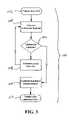
- FIG. 3is a flow chart illustrating a calibration method in accordance with an exemplary embodiment of the present invention
- FIGS. 4-7are illustrations of a pressure transducer with increased stability for use as the inflow pressure sensor or endocardial pressure sensor with the LVAD shown in FIG. 1 according to an exemplary embodiment of the present invention.
- FIGS. 8A and 8Bare schematic illustrations of internal reference pressure sensors for use in correcting for variations in barometric pressure.
- FIG. 2an endocardial pressure sensor is described that may be implanted in or on the heart to directly measure LV pressure and detect ventricular collapse, for the purpose of preventing ventricular collapse and for diagnostic purposes.
- FIG. 3a calibration technique that permits the feedback mechanism of the VAD to be periodically recalibrated in a simple and non-invasive manner addresses the problem of sensor drift.
- FIGS. 4-7a pressure transducer with improved long-term stability is described to address the problem of sensor drift.
- AFP type LVADfor purposes of illustration only.
- the embodiments described hereinmay be applied to a variety of cardiac circulatory support devices, including both pulsatile flow and continuous flow types of right ventricular assist devices (RVADs), left ventricular assist devices (LVADs), biventricular ventricular assist devices (BVADs), and total heart pumps (i.e., artificial hearts), for example.
- RVADsright ventricular assist devices
- LVADsleft ventricular assist devices
- BVADsbiventricular ventricular assist devices
- total heart pumpsi.e., artificial hearts
- a LVAD systemis shown schematically. Except as shown and described; the LVAD system illustrated is similar to the AFP type LVAD available under the trade name HeartMate® II from Thoratec, Inc. (Pleasanton, Calif.).
- the LVAD systema plurality of internal devices 95 , including an AFP type LVAD 10 , a control circuit 20 connected to the LVAD. 10 via a bidirectional link (e.g., wire cable), and a power source/storage unit 30 (e.g., rechargeable battery) connected to the control circuit 20 .
- the LVAD 10 , control circuit 20 and power unit 30may be configured for chronic implantation.
- the power unit 30may be recharged by utilizing an external power oscillator 40 to drive an external primary coil 50 which induces current flow in a subcutaneous secondary coil 60 connected to the internal power unit 30 .
- control circuit 20may be connected to an implantable telemetry unit 25 via a bidirectional electrical connection (e.g., wire cable), which may be remotely connected to an external receiver or transceiver 35 via a wireless bidirectional link (e.g., RF, microwave, ultrasound, magnetic, etc.).
- the transceiver 35may be connected to a programmer or computer 45 to facilitate, for example, operational data download, physiological data download, programming data upload, etc.
- a barometric pressure monitor (BPM) 65may be connected to the computer 45 to facilitate barometric pressure correction as will be discussed in more detail hereinafter.
- the transceiver 35 , the computer 45 , the power oscillator 40 , the primary coil 50 , and the BPM 65may all be external to the patient (P) (i.e., not implanted) and may be collectively referred to as external devices 55 . All or some of the external devices 55 may be made sufficiently small to be attached to the patient's belt, worn on the neck as a pendant, on the wrist like a watch, in a garment or elastic band worn about the patient's chest or abdomen, or placed in a purse or briefcase.
- the LVAD 10includes an AFP 12 connected to an inflow tube 14 and an outflow tube 16 .
- the inflow tube 14is connected to the LV of the heart (H), and the outflow tube 16 is connected to the aorta (AO), thus supplementing blood flow from the LV to the arterial system of the rest of the patient's body.
- the AFP 12generally includes a rotary impeller (rotor) magnetically suspended in a hollow cylindrical motor stator. Further details of the AFP 12 design may be found in U.S. Pat. No. 5,588,812 to Taylor et al., the disclosure of which is incorporated herein by reference.
- the rotor of the AFP 12is electrically driven inside the stator at a rotational velocity sufficiently high to pump blood from the LV to the AO to satisfy the circulatory requirements of the body, and sufficiently low to avoid collapse of the LV.
- IPS 70inlet pressure sensor 70
- IPS 70is disposed in the inflow tube 14 of the LVAD 10 .
- an endocardial pressure sensor (EPS) 90may be disposed on the LV free wall adjacent the inlet port to directly measure LV pressure.
- the EPS 90may be used to measure LV pressure as a surrogate for or as a supplement to motor current measurement or inlet pressure measurement.
- the EPS 90may be used to measure LV pressure which may be used to control motor speed of the AFP 12 to maximize flow rate and minimize ventricular collapse.
- the EPS 90may be connected to the control circuit 20 to provide pressure feedback thereto for closed-loop control of the LVAD 10 .
- the control circuit 20may telemeter pressure data via telemetry unit 25 and transceiver 35 for open-loop control of the LVAD 10 by the patient or physician, utilizing computer 45 , for example.
- LV pressure obtained by EPS 90may be used alone or in combination with other feedback mechanisms such as motor current feedback or inflow pressure feedback to control the LVAD 10 .
- EPS 90an example of a suitable EPS 90 is schematically illustrated.
- the endocardial pressure sensor 90may be implanted in or on the heart to directly measure LV pressure and derive LV volume.
- the EPS 90includes a pressure transducer 92 and an electronics module 94 contained within a hermetically sealed titanium housing 96 .
- the pressure transducer 92may be a piezoresistive type transducer as described with reference to FIGS. 4-7 .
- the electronics module 94may provide excitation to the pressure transducer 92 , amplify the pressure signal, and digitally code the pressure data for communication with the control circuit 20 or the telemetry unit 25 to relay pressure data to the external transceiver.
- a temperature measurement devicemay be included within the electronics module 94 to compensate the pressure signal from temperature variations.
- Other aspects of the EPS 90may be the same or similar to those described in U.S. Patent Application Publication No. 2002/0120200 to Brockway et al., the entire disclosure of which is incorporated herein by reference.
- the proximal end of the housing 96includes an electrical feedthrough 98 to facilitate connection of the electronics module 94 to a flexible lead 80 , which may be connected to the control circuit 20 as shown in FIG. 1 .
- the distal bottom side of the housing 96includes a pressure transducer header to facilitate mounting of the pressure transducer 92 and to facilitate connection to a pressure transmission catheter (PTC) 84 .
- the housing 96may be configured for attachment to the heart wall by incorporating anchors, suture ties, etc.
- the housing 96may be fabricated of a material (e.g., ceramic) to allow telemetric transmission from one or more antennae inside the housing 96 and/or may be formed of a metallic material and include one or more antennae outside the housing 96 to allow for wireless transmission of the measured pressure signal directly to the transceiver 35 which may then transmit a signal (corrected for barometric pressure variation) back to the controller 20 .
- a materiale.g., ceramic
- the PTC 84refers pressure from the pressure measurement site (e.g., LV) to the pressure transducer 92 located inside the housing 96 .
- the PTC 84may comprise a tubular structure with a liquid-filled lumen 85 extending therethrough to a distal opening 87 or port.
- the PTC 84may comprise a wide variety of materials, constructions and dimensions depending on the particular characteristics of the bodily tissue in which the PTC 84 resides when implanted. Various materials and construction alternatives for the PTC 84 are described in U.S. Provisional Patent Application No. 60/454,823, filed Mar. 12, 2003, and entitled PRESSURE TRANSMISSION CATHETER FOR IMPLANTABLE PRESSURE SENSORS, the entire disclosure of which is incorporated herein by reference.
- the proximal end of the PTC 84is connected to the pressure transducer via a nipple tube 82 , thus establishing a fluid path from the pressure transducer 92 to the distal end of the PTC 84 .
- the proximal end of the PTC 84may include an interlocking feature to secure the PTC 84 to the nipple tube 82 .
- the nipple tube 82may. have an enlarged head as shown, and a compression band 88 may be disposed around the proximal end of the PTC 84 to provide compression onto the interlocking feature of the nipple tube 82 .
- a barrier 86such as a gel plug and/or membrane may be disposed in or over the distal opening to isolate the liquid-filled lumen of the PTC 84 from bodily fluids and to retain the fluid in the lumen, without impeding pressure transmission therethrough.
- the fluidis chosen to be a fluorinated silicone oil and the gel is chosen to be dimethyl silicone gel. Further aspects of suitable fluids and gels are described in U.S. patent application Ser. No. 10/272,489, filed Oct. 15, 2002, entitled IMPROVED BARRIERS AND METHODS FOR PRESSURE MEASUREMENT CATHETERS, the entire disclosure of which is incorporated herein by reference.
- the PTC 84may have a length of approximately 25 mm, an inside diameter of approximately 0.025 inches, and a distal shaft diameter of approximately 0.055 inches for LV pressure monitoring applications as shown and described with reference to FIG. 1 .
- Various tapers, flares, wall thicknesses, etc.may also be incorporated into the PTC 84 without significant departure from these approximate dimensions.
- the feedback mechanismmay be susceptible to drift over time.
- a piezoresistive type pressure transducermay be employed, and the zero offset of such transducers is subject to drift at a finite rate over extended periods of time.
- the feedback mechanisme.g., LV pressure, inlet pressure, or motor current
- a flow chart illustrating a calibration method 100is shown for calibration and/or recalibration of the feedback sensor (e.g., EPS 90 , IPS 70 or motor current sensor).
- the feedback sensore.g., EPS 90 , IPS 70 or motor current sensor.
- This exemplary calibration technique 100permits feedback sensors associated with a VAD to be periodically recalibrated in a simple and non-invasive manner to address the problem of calibration drift.
- This calibration methodis described with primary reference to EPS 90 , but may also be applied to other feedback mechanisms and sensors.
- this method 100involves taking sensor reading(s) (e.g., pressure measured by the EPS 90 ) while monitoring the motion of the heart wall, preferably by a non-invasive manner.
- sensor reading(s)e.g., pressure measured by the EPS 90
- a patient having an implanted VADis presented 102 at a hospital, clinic or other medical facility with suitable diagnostic capabilities. This may be done at the time of implantation or subsequent thereto.
- the ventricular function (e.g., LV function for LVADs) of the patientis observed 104 , using a technique such as trans-esophageal echo (TEE), intracardiac echo (ICE), transthoracic echo, or transluminal intraventricular pressure measurement (e.g., with a highly accurate pressure-sensing catheter such as those available from Millar Instruments (Houston, Tex.) placed in the ventricle).
- TEEtrans-esophageal echo
- ICEintracardiac echo
- transthoracic echoe.g., transluminal intraventricular pressure measurement
- transluminal intraventricular pressure measuremente.g., with a highly accurate pressure-sensing catheter such as those available from Millar Instruments (Houston, Tex.) placed in the ventricle.
- Relatively non-invasive ultrasonic techniquessuch as TEE may be preferred for most patients.
- the ventricleWith the VAD running, the ventricle is observed 106 for onset of ventricular collapse 106 , as would occur if the intraventricular pressure neared intrathoracic pressure during some portion of the cardiac cycle. If the ventricle is not nearing collapse, the pump flow rate of the VAD is incrementally increased 108 by, for example, increasing the rotational velocity of the AFP, and steps 104 and 106 are repeated. If the ventricle is starting to collapse, the pressure in the ventricle is close to intrathoracic pressure (zero), and represents a critical reference point for control of the VAD.
- the feedback sensoris calibrated 110 to correspond to near zero (or within the incremental increase of step 108 ) to establish endocardial pressure (or other feedback parameter) consistent with LV collapse.
- the feedback sensormay be calibrated by adjusting the sensor output by programming new calibrations into a memory chip associated with the sensor electronics or VAD control circuitry.
- the sensor electronicscan be designed to contain a programmable offset value (positive or negative, depending on the sign of the numerical value of the zero offset). Once the zero offset drift has been identified using this procedure, the offset can be programmed into the sensor electronics or VAD control circuitry and the sensor measurement used by VAD control electronics will be adjusted by the newly stored offset value. The feedback sensor is thus calibrated and operation of the VAD is corrected 112 for calibration drift.
- the parameter (e.g., pressure) measured by the feedback sensore.g., EPS 90
- the feedback sensore.g., EPS 90
- This methodbasically allows feedback sensor measurement at a point which the ventricle begins to collapse, and subsequent procedures may be used to adjust the feedback sensor output to this same value in order to correct for the occurrence of excessive drift.
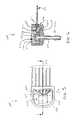
- an improved pressure sensor 200 for use in the EPS 90 and/or IPS 70is illustrated.
- the pressure sensor 200has improved long term stability to address the problem of sensor drift.
- the improved pressure sensor 200is shown as it would be implemented as an EPS 90 (PTC 84 and electronics module 94 not shown), but may be implemented as an IPS 70 by mounting the pressure sensor 200 on the outside of the inflow tube 14 and establishing a fluid path from the interior of the tube 14 to the PTC 84 .
- the improved pressure sensor 200is shown partially exploded to expose the internal components 210 .
- Pressure sensor 200inclusive of a pressure transmission catheter 84 and electronics module 94 (not shown), may be used in place of EPS 90 described previously.
- the pressure sensor 200may provide an average drift rate of less than 0.75 mmHg per month, preferably less than 0.50 mmHg per month, and more preferably 0.10 mmHg per month or less.
- Pressure sensor 200includes a lower housing unit 202 and a cover plate 204 , both of which may be formed of a chronically implantable biocompatible material such as Titanium, and may be hermetically sealed together using conventional techniques.
- a nipple tube 206extends from the bottom surface of the lower housing unit 202 for connection to a pressure transmission catheter 34 (not shown) as described previously.
- Each of a plurality of electrical leads 212extend through the lower housing unit 202 via insulative hermetically sealed rings 216 , with the exception of a ground lead 214 that may be directly connected to the lower housing unit 202 .
- the lower housing unit 202 and the cover plate 204define an internal cavity 220 , in which a plurality of internal components 210 may be disposed and covered (encapsulated) by a suitable encapsulant material 222 such as a fluoro-silicone material that partially fills the internal cavity 220 .
- a suitable encapsulant material 222such as a fluoro-silicone material that partially fills the internal cavity 220 .
- Internal cavity 220acts as a means for pressure relief to accommodate pressure variations that may occur over time due to environmental (e.g., temperature) changes, for example.
- Encapsulant material 222provides a non-hermetic seal that may permit the egress of water vapor into the internal cavity 220 , but serves to protect the otherwise exposed electrical components from corrosion and dendrite growth which may cause electrical shorts.
- hermeticmay be defined as a helium leak rate of less than 1 ⁇ 10 ⁇ 8 cm 3 /sec at 1.0 ATM.
- Suitable encapsulant materialsinclude: phenyl, di-methyl, and fluoro silicone gels and soft polymers; hydro gels; and other soft (e.g., ⁇ 60 Durometer Shore Zero Harness Scale) polymeric materials that are not immiscible in the other materials used (e.g., adhesives) in the cavity 220 .
- a pressure sensing element 230such as a piezo-resistive Wheatstone bridge type silicon strain gauge available from Sensonor of Horten, Norway, includes a plurality of wires 218 connected to the leads 212 via bonding pads 219 .
- Leads 212may comprise a platinum-iridium core coated with nickel and aluminum.
- Wires 218 and bonding pads 219may comprise aluminum, which tends to be highly corrodible in the presence of water, tends to form dendrites when exposed to a voltage potential in the presence of water vapor and ionic contaminants, tends to be susceptible to electrical shorts in the presence of water, all of which may be commonly encountered in the implanted environment. Because of these issues, encapsulant 222 serves to protect the wires 218 and pads 219 from the adverse effects associated therewith.
- FIG. 6which is a cross-sectional view taken along line A-A in FIG. 5 (including top cover), the structure of the internal components 210 may be more readily appreciated.
- the bottom portion of the sensor element 230is mounted to a constraint 234 (also referred to as pedestal or stand-off), and a reference cover 232 is mounted to the top portion of the sensor element 230 to define a reference cavity 236 (e.g., vacuum) therebetween.
- the bottom portion of the constraint 234is mounted to the lower housing unit 202 in alignment with the nipple tube.
- a fluid pathis defined via lumen 238 that extends from the underside of the sensing element 230 (referred to as backside access), through the constraint 234 , through the nipple tube 206 , and into the PTC mounted thereto, thus enabling fluidic transmission of pressure signals from the distal end of the PTC to the sensor element 230 .
- the sensing element 230 , reference cover 232 , and constraint 234may be collectively referred to as a sensor die.
- the housing 202 to which the sensor die is mountedmay be referred to as a header.
- the bond between the sensor dies and the headermay be referred to as a die mount.
- the sensor element 230may comprise silicon
- both the constraint 234 and the reference cover 232may comprise a borosilicate glass (e.g., Pyrex or silica).
- the reference cover 232may be mounted to the sensor element 230 by a glass frit bond, and the sensor element 230 may be mounted to the constraint 234 by an anodic bond, or visa-versa.
- the constraint 234may be mounted to the header by a dy-methyl silicone adhesive borid, an epoxy bond, etc.
- the die mountmay be rigid, referred to as a hard mount, as with a solder joint.
- the die mountmay be flexible, referred to as a soft mount, as with an adhesive joint.
- a soft mountprovides an effective strain relief that isolates the sensor element 230 from header stress, and allows the sensor element 230 to respond only to pressure variations in the lumen 238 .
- temperature deviations from the temperature at which the die mount was formedresults in a buildup of stress at the die mount. If a hard mount is used, the stress is transferred to the sensor element 230 and is indistinguishable from stresses caused by true pressure changes in the lumen 238 .
- the constraint 234may comprise a flexible thin metallic structure such as a bellows or an annular flange.
- Tube 534extends into lumen 238 and provides a lumen in communication with the cavity 236 .
- Tube 534may comprise borosilicate glass (e.g., PyrexTM or silica) or a low expansion iron-nickel-cobalt alloy (e.g., KovarTM) and may be hermetically sealed to the housing 202 by joint 532 , which may comprise a braze, solder, or glass solder (low melt temperature glass).
- the housing 202may comprise a metal (e.g., Ti) which readily accepts a braze, solder or glass solder joint 532 .
- tube 534the outside surface of the glass tube 534 readily accepts a glass solder joint 532 without modification, but may be metalized to facilitate a braze or solder joint 532 .
- the tube 534may be hermetically sealed to the constraint 234 by a joint 536 such as a solder joint facilitated by metalizing the adjacent surfaces of the glass tube 534 and the glass constraint 234 .
- joint 536may comprise a glass solder joint but care must be taken to avoid thermal damage to the constraint 234 and other components of the sensor.
- the tube 534 and the constraintmay be formed of the same or similar glass material (e.g., Pyrex or silica) to provide the same or similar coefficient of thermal expansion in order to minimize thermally induced stress therebetween.
- the tube 534 and the constraintmay be also be formed of dissimilar materials (e.g., Kovar and Pyrex) and still provide strain relief effects by virtue of the tube geometry which isolates the constraint from the housing.
- the tube 534acts as a strain relief to isolate the constraint 234 from the housing 202 in order to minimize mechanically and thermally induces stress therebetween, while maintaining a hermetic seal, thereby lowering drift and preventing the migration of water into the interior cavity 220 of the sensor 200 .
- the interior cavity 220may be filled with an encapsulant as described previously, but the provision of hermetic seals 532 and 536 minimizes or eliminates the need therefor.
- an encapsulantmay be utilized if the seals 532 and 536 are not perfectly hermetic, but provide low permeability to water (e.g., epoxy bonds).
- the pressure measurementsmay be influenced by external pressure changes (i.e., changes in barometric pressure), potentially leading to inaccurate pressure feedback data and improper LVAD operation if not corrected.
- external pressure changesi.e., changes in barometric pressure
- a number of different pressure correction schemesare described herein to address barometric pressure correction of pressure feedback measurements for LVAD operation.
- An example of a general approach to barometric pressure correctionis to simultaneously take barometric pressure readings with measurements taken by the EPS 90 and/or IPS 70 , and subtract the barometric reading from the internal pressure measurement.
- An example of another general approachis to occasionally take barometric pressure readings, store the reading, and, when needed, subtract the stored value from the measurements taken by the EPS 90 and/or IPS 70 .
- the subtraction stepmay be performed by the control circuit 20 or by one of the external devices 55 such as computer 45 . If performed by the control circuit 20 , the barometric pressure reading is taken by the external device 55 and transmitted to (and optionally stored in) the control circuit 20 . If performed by the computer 45 , the internal pressure measurement is taken by the EPS 90 and/or IPS 70 and transmitted to the computer 45 . The corrected pressure values may then be transmitted to controller 20 via transceiver 35 and telemetry unit 25 . It may be preferable to have the control circuit 20 store the barometric reading and perform the subtraction step in order to provide more efficient closed-loop feedback control of the LVAD 10 .
- an external barometric pressure monitor (BPM) 65measures barometric pressure at specified times. Measurements obtained by the BPM 65 are representative of the barometric pressure to which the body of the patient is exposed.
- the BPM 65is powered on, and an initial barometric pressure measurement is taken and stored in memory (e.g., in BPM 65 or computer 45 ).
- the barometric pressure measurementis transmitted to the internal control circuit 20 , where it is stored in memory.
- the control circuit 20is thus able to subtract the stored barometric pressure measurement from the measurements taken from EPS 90 and/or IPS 70 .
- Each subsequent barometric pressure measurement taken by the BPM 65is compared to the stored measurement and evaluated to determine if the difference between that measurement and the stored measurement exceeds a predetermined threshold (e.g. 0.5 mmHg). If the difference is less than the threshold, no further action is taken on that measurement. If the difference is greater than or equal to the threshold, then that new value is saved in memory and transmitted to the control circuit 20 for use as the updated barometric pressure measurement.
- a predetermined thresholde.g. 0.5 mmHg
- Barometric pressuremay alternatively be measured through the use of a pressure sensor located within the body.
- FIGS. 8A and 8Bschematically illustrate examples of suitable internal reference pressure sensors 800 A, and 800 B, respectively.
- the internal reference pressure sensor 800 A or 800 Bmay be implanted inside the body, such as in the thorax.
- the internal reference pressure sensors 800 A/ 800 Beach include a housing 96 containing a pressure transducer 92 connected to electronics module 94 , which is connected to lead 802 via feedthrough 98 , similar to embodiments described previously.
- the internal barometric pressure sensor 800 A/ 800 Bmay be directly linked to the controller 20 of the VAD 10 via lead 802 .
- the pressure sensor 800 Aincludes a sensing surface 810 which, together with housing 96 , defines an internal cavity 812 that may be filled with an oil or other liquid such as a perfluorocarbon, or fluorinated silicone, for example, such as the fill fluid 85 described previously.
- the sensing surface 810which may be formed of a metallic membrane for example, functions as a diaphragm to transmit external pressure via the fill fluid to the pressure transducer 92 . Because the housing 96 may be relatively rigid, the sensing surface 810 may include bellows 814 or other suspension structure to efficiently deflect in response to pressure variations.
- the sensing surface 810may have a relatively large surface area (>20 mm sq) in order to accurately sense pressure following the formation of scar tissue on the sensor surface, as is common if implanted in tissue.
- the pressure sensor 800 Bincludes a balloon-type sensing surface 820 which may provide relatively more surface area.
- the balloon-type sensing surface 820which may be formed of a polymeric material such as urethane for example, may contain a fill fluid as described above and to transmit external pressure via the fill fluid to the pressure transducer 92 .
- the fill fluidmay comprise a fluid that has negligible migration through the balloon material, such as the fluids described above.
- the balloon-type sensing surface 820may have a relatively large surface area (>20 mm sq) in order to accurately sense pressure following the formation of scar tissue as described previously.
- the measurementsmay be subject to large sudden changes that should be ignored when used for correcting a LV pressure for barometric pressure.
- large sudden changesmay be caused by coughing, movements, impacts such as jumping, falling etc.
- One approach for ignoring or effectively eliminating such large sudden changesis to perform a moving average of the measurements in addition to a median filtering that removes outlier measurements that occur during the events.
- Another approachis to revert to other feedback control means (e.g., motor current or flow) when a large sudden change in pressure is detected, and return to pressure, feedback control when the barometric (reference) pressure measurements stabilize.
- barometric pressuremay be corrected by transmitting pressure from the in vivo sensor to a device worn on the patient or located nearby, substantially as described above.
- the BPM 65receives via transceiver 35 and telemetry unit 25 an in-vivo pressure signal (e.g., from EPS 90 ), corrects for ambient pressure changes, and transmits the corrected signal back to the VAD control circuit 20 .
- the BPM 65may optionally store pressure data in memory storage device such as computer 45 for later evaluation for use in clinical assessment of the patient, or for evaluation of VAD 10 function.
- a corrected pressure signalmay not always be reliably available. This situation may arise in situations where the patient loses the external device that measures barometric pressure (e.g., BPM 65 ) or the telemetry link from the external transceiver 35 to the internal telemetry unit 25 is lost or corrupted by electrical noise, or when some event causes a sudden artifact in the barometric pressure signal that is irrelevant to control of the VAD. This is particularly important if the patient is in a situation where ambient pressure is changing rapidly. One such situation is where the patient is riding an elevator from the ground floor of a building to a point several stories above ground level. In such a case, the ambient pressure may change by several mmHg. If the VAD 10 were solely dependent on measured pressure, and one of the foregoing situations were to arise, an inappropriate response in VAD control may take place.
- BPM 65barometric pressure
- One approach to dealing with this situationis to employ motor current or pump output flow as a primary feedback means, and use pressure (e.g., ventricular pressure as measured by EPS 90 ) to correct or calibrate motor current on a frequent basis.
- pressuree.g., ventricular pressure as measured by EPS 90
- pressuremay be used to calibrate motor current only at times when the ventricular pressure is verified as accurate and reliable.
- This approachhas a secondary advantage in that continuous pressure recording is not required, which may allow for power conservation of the internal devices 95 .
- ventricular pressuremay be reliable and accurate.
- certain evaluation criteriamay be applied. These criteria may be used alone or in combination.
- a first example of such criteriais acceptable change in ambient pressure. If ambient pressure has changed by less than a predetermined value in a predetermined period of time (e.g., ⁇ 1 mmHg in the past 5 minutes), the ventricular pressure measurement may be found reliable.
- a predetermined value in a predetermined period of timee.g., ⁇ 1 mmHg in the past 5 minutes
- a second example of such criteriais valid telemetry link.
- the telemetry link between the external transceiver 35 and the internal telemetry unit 25may be deemed reliable through positive verification of the link performance via error detection schemes such as cyclic redundancy checks or other means known in the art.
- a third example of such criteriais recent recalibration.
- the systemmay require physician recalibration of the in vivo pressure sensor on a regular basis using recalibration methods previously described.
- the systemmay contain a reminder. If the device has not been recalibrated within the specified time, the pressure measurements would be deemed to be unreliable.
- a fourth example of such criteriais valid pressure signal.
- the pressure signalmay be evaluated to determine that the PTC is patent at the time that pressure measurements are obtained. This could be done by assessing variability of the pressure signal over a fixed time period. This assessment may be performed by evaluating variability in one or more parameters derived from the signal, such as max dP/dt, systolic pressure, diastolic pressure or mean pressure.
- One approachis to establish a measure of variability, such as parameter variance, standard error, etc., at the time of implantation. Occasional evaluation of variability may be performed automatically or upon activation by a physician during an office visit, for example. The assessment could be done by the computer 45 or the VAD controller 20 .
- Another approach to dealing with a potentially unreliable pressure signalis to use pressure as the primary feedback parameter and use the motor current as a back-up feedback when the pressure signal is found unreliable using criteria described above.
- the reliability of the pressure signalmay be performed in real time, and if the pressure signal is deemed unreliable, the VAD control circuit reverts to motor current feedback, or another feedback means (e.g., flow measurement).
- the present inventionprovides, in exemplary no-limiting embodiments, a variety of devices, systems and methods for providing effective, long term and reliable use of pressure feedback in VADs. Further, those skilled in the art will recognize that the present invention may be manifested in a variety of forms other than the specific embodiments described and contemplated herein. Accordingly, departures in form and detail may be made without departing from the scope and spirit of the present invention as described in the appended claims.
Landscapes
- Health & Medical Sciences (AREA)
- Engineering & Computer Science (AREA)
- Heart & Thoracic Surgery (AREA)
- Cardiology (AREA)
- Hematology (AREA)
- Mechanical Engineering (AREA)
- Anesthesiology (AREA)
- Biomedical Technology (AREA)
- Life Sciences & Earth Sciences (AREA)
- Animal Behavior & Ethology (AREA)
- General Health & Medical Sciences (AREA)
- Public Health (AREA)
- Veterinary Medicine (AREA)
- Medical Informatics (AREA)
- External Artificial Organs (AREA)
- Measuring And Recording Apparatus For Diagnosis (AREA)
- Measuring Pulse, Heart Rate, Blood Pressure Or Blood Flow (AREA)
Abstract
Description
Claims (5)
Priority Applications (1)
| Application Number | Priority Date | Filing Date | Title |
|---|---|---|---|
| US10/993,826US7520850B2 (en) | 2003-11-19 | 2004-11-19 | Feedback control and ventricular assist devices |
Applications Claiming Priority (2)
| Application Number | Priority Date | Filing Date | Title |
|---|---|---|---|
| US52340803P | 2003-11-19 | 2003-11-19 | |
| US10/993,826US7520850B2 (en) | 2003-11-19 | 2004-11-19 | Feedback control and ventricular assist devices |
Publications (2)
| Publication Number | Publication Date |
|---|---|
| US20050107658A1 US20050107658A1 (en) | 2005-05-19 |
| US7520850B2true US7520850B2 (en) | 2009-04-21 |
Family
ID=34632778
Family Applications (1)
| Application Number | Title | Priority Date | Filing Date |
|---|---|---|---|
| US10/993,826Expired - Fee RelatedUS7520850B2 (en) | 2003-11-19 | 2004-11-19 | Feedback control and ventricular assist devices |
Country Status (2)
| Country | Link |
|---|---|
| US (1) | US7520850B2 (en) |
| WO (1) | WO2005051838A2 (en) |
Cited By (57)
| Publication number | Priority date | Publication date | Assignee | Title |
|---|---|---|---|---|
| US8066628B1 (en) | 2010-10-22 | 2011-11-29 | Nupulse, Inc. | Intra-aortic balloon pump and driver |
| US8668526B2 (en)* | 2010-06-07 | 2014-03-11 | Thoratec Corporation | Bi-ventricular percutaneous cable |
| WO2015160995A1 (en)* | 2014-04-15 | 2015-10-22 | Thoratec Corporation | Ventricular assist devices |
| US9463268B2 (en) | 2010-09-07 | 2016-10-11 | Paul A. Spence | Cannula systems and methods |
| US9585991B2 (en) | 2012-10-16 | 2017-03-07 | Heartware, Inc. | Devices, systems, and methods for facilitating flow from the heart to a blood pump |
| US9687596B2 (en) | 2009-02-27 | 2017-06-27 | Tci Llc | Prevention of aortic valve fusion |
| WO2017178959A1 (en) | 2016-04-11 | 2017-10-19 | CorWave SA | Implantable pump system having an undulating membrane |
| US9801988B2 (en) | 2010-09-24 | 2017-10-31 | Tc1 Llc | Generating artificial pulse |
| US9808283B2 (en) | 2013-12-04 | 2017-11-07 | Heartware, Inc. | Apparatus and methods for cutting an atrial wall |
| US10166319B2 (en) | 2016-04-11 | 2019-01-01 | CorWave SA | Implantable pump system having a coaxial ventricular cannula |
| US10188779B1 (en) | 2017-11-29 | 2019-01-29 | CorWave SA | Implantable pump system having an undulating membrane with improved hydraulic performance |
| US10213537B2 (en) | 2016-07-19 | 2019-02-26 | Heartware, Inc. | Ventricular assist devices and integrated sensors thereof |
| US20200101209A1 (en)* | 2018-09-27 | 2020-04-02 | Heartware, Inc. | Map estimation on vad patients |
| US10722631B2 (en) | 2018-02-01 | 2020-07-28 | Shifamed Holdings, Llc | Intravascular blood pumps and methods of use and manufacture |
| US10780209B2 (en) | 2017-03-29 | 2020-09-22 | Tc1 Llc | Adjusting pump protocol based on irregular heart rhythm |
| WO2020188453A1 (en) | 2019-03-15 | 2020-09-24 | CorWave SA | Systems and methods for controlling an implantable blood pump |
| US10835654B2 (en) | 2017-03-29 | 2020-11-17 | Tc1 Llc | Pressure sensing ventricular assist devices and methods of use |
| US10933181B2 (en) | 2017-03-31 | 2021-03-02 | CorWave SA | Implantable pump system having a rectangular membrane |
| US11065436B2 (en) | 2017-03-29 | 2021-07-20 | Tc1 Llc | Communication methods and architecture for heart treatment systems |
| WO2021176423A1 (en) | 2020-03-06 | 2021-09-10 | CorWave SA | Implantable blood pumps comprising a linear bearing |
| US11167123B2 (en) | 2018-03-19 | 2021-11-09 | Tc1 Llc | Coordinated ventricular assist and cardiac rhythm management devices and methods |
| US11185677B2 (en) | 2017-06-07 | 2021-11-30 | Shifamed Holdings, Llc | Intravascular fluid movement devices, systems, and methods of use |
| US11241570B2 (en) | 2018-07-17 | 2022-02-08 | Tc1 Llc | Systems and methods for inertial sensing for VAD diagnostics and closed loop control |
| US11368081B2 (en) | 2018-01-24 | 2022-06-21 | Kardion Gmbh | Magnetic coupling element with a magnetic bearing function |
| US11511103B2 (en) | 2017-11-13 | 2022-11-29 | Shifamed Holdings, Llc | Intravascular fluid movement devices, systems, and methods of use |
| US11512689B2 (en) | 2017-11-10 | 2022-11-29 | CorWave SA | Undulating-membrane fluid circulator |
| US11517740B2 (en) | 2018-03-15 | 2022-12-06 | Tc1 Llc | Methods for controlling a left ventricular assist device |
| US11654275B2 (en) | 2019-07-22 | 2023-05-23 | Shifamed Holdings, Llc | Intravascular blood pumps with struts and methods of use and manufacture |
| US11699551B2 (en) | 2020-11-05 | 2023-07-11 | Kardion Gmbh | Device for inductive energy transmission in a human body and use of the device |
| US11724089B2 (en) | 2019-09-25 | 2023-08-15 | Shifamed Holdings, Llc | Intravascular blood pump systems and methods of use and control thereof |
| US11752354B2 (en) | 2018-05-02 | 2023-09-12 | Kardion Gmbh | Transmitter unit comprising a transmission coil and a temperature sensor |
| WO2023209547A1 (en) | 2022-04-26 | 2023-11-02 | CorWave SA | Blood pumps having an encapsulated actuator |
| US11881721B2 (en) | 2018-05-02 | 2024-01-23 | Kardion Gmbh | Wireless energy transfer system with fault detection |
| US11964145B2 (en) | 2019-07-12 | 2024-04-23 | Shifamed Holdings, Llc | Intravascular blood pumps and methods of manufacture and use |
| US11996699B2 (en) | 2018-05-02 | 2024-05-28 | Kardion Gmbh | Receiving unit, transmission unit, power transmission system and method for wireless power transmission |
| US12017059B2 (en) | 2022-11-15 | 2024-06-25 | CorWave SA | Implantable heart pump systems including an improved apical connector and/or graft connector |
| US12102815B2 (en) | 2019-09-25 | 2024-10-01 | Shifamed Holdings, Llc | Catheter blood pumps and collapsible pump housings |
| US12121713B2 (en) | 2019-09-25 | 2024-10-22 | Shifamed Holdings, Llc | Catheter blood pumps and collapsible blood conduits |
| US12144976B2 (en) | 2018-06-21 | 2024-11-19 | Kardion Gmbh | Method and device for detecting a wear condition of a ventricular assist device and for operating same, and ventricular assist device |
| US12150647B2 (en) | 2016-06-06 | 2024-11-26 | Kardion Gmbh | Method for punching a lumen and implanting an implant device |
| US12156978B2 (en) | 2019-05-17 | 2024-12-03 | Nupulsecv, Inc. | Intravascularly delivered blood pumps and associated devices, systems, and methods |
| US12161857B2 (en) | 2018-07-31 | 2024-12-10 | Shifamed Holdings, Llc | Intravascular blood pumps and methods of use |
| US12178554B2 (en) | 2018-06-06 | 2024-12-31 | Kardion Gmbh | Systems and methods for determining a viscosity of a fluid |
| US12194287B2 (en) | 2018-05-30 | 2025-01-14 | Kardion Gmbh | Method of manufacturing electrical conductor tracks in a region of an intravascular blood pump |
| US12201821B2 (en) | 2018-06-06 | 2025-01-21 | Kardion Gmbh | Method for determining a flow rate of a fluid flowing through an implanted vascular support system, and implantable vascular support system |
| US12220570B2 (en) | 2018-10-05 | 2025-02-11 | Shifamed Holdings, Llc | Intravascular blood pumps and methods of use |
| US12222267B2 (en) | 2018-06-06 | 2025-02-11 | Kardion Gmbh | Analysis device and method for analyzing a viscosity of a fluid |
| US12230868B2 (en) | 2018-05-02 | 2025-02-18 | Kardion Gmbh | Device for inductive energy transfer into a human body, for example, and use of said device |
| US12233250B2 (en) | 2018-05-02 | 2025-02-25 | Kardion Gmbh | Device for inductive energy transmission into a human body and use thereof |
| US12257427B2 (en) | 2022-11-15 | 2025-03-25 | CorWave SA | Implantable heart pump systems including an improved apical connector and/or graft connector |
| US12257424B2 (en) | 2018-06-06 | 2025-03-25 | Kardion Gmbh | Implantable ventricular assist system and method for operating same |
| US12310708B2 (en) | 2018-06-06 | 2025-05-27 | Kardion Gmbh | Systems and methods for determining a flow speed of a fluid flowing through a cardiac assist device |
| US12311160B2 (en) | 2018-06-06 | 2025-05-27 | Kardion Gmbh | Method and system for determining the speed of sound in a fluid in the region of a cardiac support system |
| US12324906B2 (en) | 2018-06-06 | 2025-06-10 | Kardion Gmbh | Systems and methods for determining a total blood volume flow in a cardiac support system and vascular support system |
| US12377256B2 (en) | 2018-06-06 | 2025-08-05 | Kardion Gmbh | Cardiac support system flow measurement using pressure sensors |
| US12403296B2 (en) | 2018-05-30 | 2025-09-02 | Kardion Gmbh | Apparatus for anchoring a ventricular assist system in a blood vessel, operating method, production method for producing an apparatus and ventricular assist system |
| US12409310B2 (en) | 2019-12-11 | 2025-09-09 | Shifamed Holdings, Llc | Descending aorta and vena cava blood pumps |
Families Citing this family (71)
| Publication number | Priority date | Publication date | Assignee | Title |
|---|---|---|---|---|
| US7691723B2 (en)* | 2005-01-07 | 2010-04-06 | Honeywell International Inc. | Bonding system having stress control |
| US8657875B2 (en)* | 2005-09-26 | 2014-02-25 | Abiomed, Inc. | Method and apparatus for pumping blood |
| US20070083077A1 (en)* | 2005-10-06 | 2007-04-12 | Alpha Dev, Llc. | Total artificial heart system for auto-regulating flow and pressure balance |
| US20070142923A1 (en) | 2005-11-04 | 2007-06-21 | Ayre Peter J | Control systems for rotary blood pumps |
| JP4856194B2 (en)* | 2006-01-27 | 2012-01-18 | サーキュライト・インコーポレーテッド | Cardiac assist system |
| AU2007201127B2 (en)* | 2006-03-23 | 2012-02-09 | Thoratec Corporation | System For Preventing Diastolic Heart Failure |
| US8333686B2 (en)* | 2006-08-30 | 2012-12-18 | Circulite, Inc. | Cannula insertion devices, systems, and methods including a compressible member |
| US7905823B2 (en)* | 2006-08-30 | 2011-03-15 | Circulite, Inc. | Devices, methods and systems for establishing supplemental blood flow in the circulatory system |
| EP2650029B1 (en) | 2006-08-30 | 2015-01-14 | CircuLite, Inc. | Devices and systems for establishing supplemental blood flow in the circulatory system |
| EP2061531B1 (en)* | 2006-09-14 | 2016-04-13 | CircuLite, Inc. | Intravascular blood pump and catheter |
| WO2009011993A1 (en)* | 2007-07-19 | 2009-01-22 | Circulite, Inc. | Cannula for heart chamber implantation and related systems and methods |
| US8343029B2 (en) | 2007-10-24 | 2013-01-01 | Circulite, Inc. | Transseptal cannula, tip, delivery system, and method |
| AU2014202152A1 (en)* | 2007-12-03 | 2014-05-15 | Covidien Ag | Cordless hand-held ultrasonic cautery cutting device |
| US8334468B2 (en) | 2008-11-06 | 2012-12-18 | Covidien Ag | Method of switching a cordless hand-held ultrasonic cautery cutting device |
| US8061014B2 (en)* | 2007-12-03 | 2011-11-22 | Covidien Ag | Method of assembling a cordless hand-held ultrasonic cautery cutting device |
| US20090143800A1 (en) | 2007-12-03 | 2009-06-04 | Derek Dee Deville | Cordless Hand-Held Ultrasonic Cautery Cutting Device |
| US9314261B2 (en) | 2007-12-03 | 2016-04-19 | Covidien Ag | Battery-powered hand-held ultrasonic surgical cautery cutting device |
| US8425545B2 (en)* | 2007-12-03 | 2013-04-23 | Covidien Ag | Cordless hand-held ultrasonic cautery cutting device and method |
| US9107690B2 (en) | 2007-12-03 | 2015-08-18 | Covidien Ag | Battery-powered hand-held ultrasonic surgical cautery cutting device |
| US8663262B2 (en) | 2007-12-03 | 2014-03-04 | Covidien Ag | Battery assembly for battery-powered surgical instruments |
| US9017355B2 (en) | 2007-12-03 | 2015-04-28 | Covidien Ag | Battery-powered hand-held ultrasonic surgical cautery cutting device |
| US8226712B1 (en) | 2008-06-13 | 2012-07-24 | Newheart Medical Devices Llc | Total artificial heart system for auto-regulating flow and pressure |
| US8449444B2 (en)* | 2009-02-27 | 2013-05-28 | Thoratec Corporation | Blood flow meter |
| US20100222878A1 (en)* | 2009-02-27 | 2010-09-02 | Thoratec Corporation | Blood pump system with arterial pressure monitoring |
| US20100222633A1 (en)* | 2009-02-27 | 2010-09-02 | Victor Poirier | Blood pump system with controlled weaning |
| US20100222635A1 (en)* | 2009-02-27 | 2010-09-02 | Thoratec Corporation | Maximizing blood pump flow while avoiding left ventricle collapse |
| US20100249491A1 (en)* | 2009-03-27 | 2010-09-30 | Circulite, Inc. | Two-piece transseptal cannula, delivery system, and method of delivery |
| US8460168B2 (en)* | 2009-03-27 | 2013-06-11 | Circulite, Inc. | Transseptal cannula device, coaxial balloon delivery device, and methods of using the same |
| US8628460B2 (en)* | 2009-09-21 | 2014-01-14 | Heartware, Inc. | Hard-wired implanted controller system |
| US20110112353A1 (en)* | 2009-11-09 | 2011-05-12 | Circulite, Inc. | Bifurcated outflow cannulae |
| US20120302938A1 (en)* | 2010-03-19 | 2012-11-29 | University Of Washington | Drainage systems for excess body fluids and associated methods |
| CA2793672C (en) | 2010-03-19 | 2020-08-04 | University Of Washington | Drainage systems for excess body fluids |
| JP5852122B2 (en) | 2010-09-24 | 2016-02-03 | ソーラテック コーポレイション | Control of circulation assist device |
| JP6039586B2 (en) | 2011-03-02 | 2016-12-07 | ソーラテック コーポレイション | Ventricular cuff |
| DE102011106142A1 (en)* | 2011-06-10 | 2012-12-27 | Rheinisch-Westfälische Technische Hochschule Aachen | Blood collection cannula of a heart function replacing or supporting pump |
| US20180126053A1 (en)* | 2011-08-19 | 2018-05-10 | Leviticus Cardio Ltd. | Wristwatch for monitoring operation of an implanted ventricular assist device |
| WO2013112550A1 (en)* | 2012-01-24 | 2013-08-01 | Thoratec Corporation | Driveline cable assembly |
| US9199019B2 (en) | 2012-08-31 | 2015-12-01 | Thoratec Corporation | Ventricular cuff |
| US9981076B2 (en) | 2012-03-02 | 2018-05-29 | Tc1 Llc | Ventricular cuff |
| JP6034889B2 (en)* | 2012-03-05 | 2016-11-30 | ソーラテック コーポレイション | Modular implantable medical pump |
| WO2014033197A1 (en) | 2012-08-31 | 2014-03-06 | Sanofi-Aventis Deutschland Gmbh | Drug delivery device |
| KR20150052215A (en) | 2012-09-05 | 2015-05-13 | 하트웨어, 인코포레이티드 | Vad integrated flow sensor |
| TWI631930B (en)* | 2013-04-01 | 2018-08-11 | 美盛醫電股份有限公司 | Physiology signal sensing device |
| US9694123B2 (en) | 2014-04-15 | 2017-07-04 | Tc1 Llc | Methods and systems for controlling a blood pump |
| CN104740706A (en)* | 2015-04-21 | 2015-07-01 | 焦雷 | A medical device blood pump |
| EP3316776B1 (en)* | 2015-06-30 | 2020-09-23 | Koninklijke Philips N.V. | Control device for a medical aerosol delivery device |
| US10368898B2 (en) | 2016-05-05 | 2019-08-06 | Covidien Lp | Ultrasonic surgical instrument |
| US10894116B2 (en) | 2016-08-22 | 2021-01-19 | Tc1 Llc | Heart pump cuff |
| EP3311859B1 (en) | 2016-10-19 | 2019-12-04 | Abiomed Europe GmbH | Ventricular assist device control |
| US11235137B2 (en) | 2017-02-24 | 2022-02-01 | Tc1 Llc | Minimally invasive methods and devices for ventricular assist device implantation |
| US10571435B2 (en) | 2017-06-08 | 2020-02-25 | Covidien Lp | Systems and methods for digital control of ultrasonic devices |
| AU2018279862B2 (en) | 2017-06-09 | 2023-07-06 | Abiomed, Inc. | Determination of cardiac parameters for modulation of blood pump support |
| WO2019016802A1 (en) | 2017-07-17 | 2019-01-24 | Livemetric (Medical) S.A. | Method and system for ventricular assistive device adjustment using a wearable device |
| US11259832B2 (en) | 2018-01-29 | 2022-03-01 | Covidien Lp | Ultrasonic horn for an ultrasonic surgical instrument, ultrasonic surgical instrument including the same, and method of manufacturing an ultrasonic horn |
| US11246617B2 (en) | 2018-01-29 | 2022-02-15 | Covidien Lp | Compact ultrasonic transducer and ultrasonic surgical instrument including the same |
| US11246621B2 (en) | 2018-01-29 | 2022-02-15 | Covidien Lp | Ultrasonic transducers and ultrasonic surgical instruments including the same |
| US11229449B2 (en) | 2018-02-05 | 2022-01-25 | Covidien Lp | Ultrasonic horn, ultrasonic transducer assembly, and ultrasonic surgical instrument including the same |
| US10582944B2 (en) | 2018-02-23 | 2020-03-10 | Covidien Lp | Ultrasonic surgical instrument with torque assist feature |
| US10960118B2 (en) | 2018-07-31 | 2021-03-30 | Abiomed, Inc. | Systems and methods for controlling a heart pump to minimize myocardial oxygen consumption |
| DE102018218770A1 (en) | 2018-11-02 | 2020-05-07 | Kardion Gmbh | System and method for controlling a cardiac assist system |
| EP3873554B1 (en)* | 2018-12-21 | 2024-11-20 | Tc1 Llc | Implantable blood pump assembly including pressure sensor and methods of assembling same |
| US11478268B2 (en) | 2019-08-16 | 2022-10-25 | Covidien Lp | Jaw members for surgical instruments and surgical instruments incorporating the same |
| US12023065B2 (en) | 2019-09-03 | 2024-07-02 | Covidien Lp | Bi-stable spring-latch connector for ultrasonic surgical instruments |
| US11666357B2 (en) | 2019-09-16 | 2023-06-06 | Covidien Lp | Enclosure for electronics of a surgical instrument |
| US12004769B2 (en) | 2020-05-20 | 2024-06-11 | Covidien Lp | Ultrasonic transducer assembly for an ultrasonic surgical instrument |
| US20220117623A1 (en) | 2020-10-15 | 2022-04-21 | Covidien Lp | Ultrasonic surgical instrument |
| US12426912B2 (en) | 2021-06-17 | 2025-09-30 | Covidien Lp | Surgical instruments, systems, and methods for frequency dithering control functionality |
| US11717312B2 (en) | 2021-10-01 | 2023-08-08 | Covidien Lp | Surgical system including blade visualization markings |
| US20250303137A1 (en)* | 2024-03-29 | 2025-10-02 | Abiomed, Inc. | Methods and systems for correcting sensor drift for an intravascular blood pump |
| WO2025208013A1 (en)* | 2024-03-29 | 2025-10-02 | Abiomed, Inc. | Methods and systems for detecting sensor drift for an intravascular blood pump |
| CN119818827B (en)* | 2025-03-18 | 2025-07-11 | 安徽通灵仿生科技有限公司 | A pulse control system and device for a ventricular catheter pump |
Citations (7)
| Publication number | Priority date | Publication date | Assignee | Title |
|---|---|---|---|---|
| US5588812A (en) | 1995-04-19 | 1996-12-31 | Nimbus, Inc. | Implantable electric axial-flow blood pump |
| US5888242A (en) | 1996-11-01 | 1999-03-30 | Nimbus, Inc. | Speed control system for implanted blood pumps |
| US6171253B1 (en) | 1999-05-04 | 2001-01-09 | Apex Medical, Inc. | Flat tube pressure sensor |
| US6481292B1 (en) | 1999-12-24 | 2002-11-19 | Apex Medical, Inc. | Dual pressure monitor |
| US20030045772A1 (en) | 2001-08-16 | 2003-03-06 | Sanford Reich | Physiological heart pump control |
| US6540699B1 (en) | 1999-05-18 | 2003-04-01 | Sonometrics Corporation | System for incorporating sonomicrometer functions into medical instruments and implantable biomedical devices |
| US6949066B2 (en)* | 2002-08-21 | 2005-09-27 | World Heart Corporation | Rotary blood pump diagnostics and cardiac output controller |
- 2004
- 2004-11-19USUS10/993,826patent/US7520850B2/ennot_activeExpired - Fee Related
- 2004-11-19WOPCT/US2004/039274patent/WO2005051838A2/enactiveApplication Filing
Patent Citations (8)
| Publication number | Priority date | Publication date | Assignee | Title |
|---|---|---|---|---|
| US5588812A (en) | 1995-04-19 | 1996-12-31 | Nimbus, Inc. | Implantable electric axial-flow blood pump |
| US5888242A (en) | 1996-11-01 | 1999-03-30 | Nimbus, Inc. | Speed control system for implanted blood pumps |
| US6171253B1 (en) | 1999-05-04 | 2001-01-09 | Apex Medical, Inc. | Flat tube pressure sensor |
| US6367333B1 (en) | 1999-05-04 | 2002-04-09 | Apex Medical, Inc. | Notch diaphragm pressure sensor |
| US6540699B1 (en) | 1999-05-18 | 2003-04-01 | Sonometrics Corporation | System for incorporating sonomicrometer functions into medical instruments and implantable biomedical devices |
| US6481292B1 (en) | 1999-12-24 | 2002-11-19 | Apex Medical, Inc. | Dual pressure monitor |
| US20030045772A1 (en) | 2001-08-16 | 2003-03-06 | Sanford Reich | Physiological heart pump control |
| US6949066B2 (en)* | 2002-08-21 | 2005-09-27 | World Heart Corporation | Rotary blood pump diagnostics and cardiac output controller |
Non-Patent Citations (2)
| Title |
|---|
| Bullister et al., "Physiologic Control Algorithms for Rotary Blood Pumps Using Pressure Sensor Input," Artificial Organs, 26(11):931-938 (2002). |
| Olsen, D. B., "Presidential Address, The History of Continuous-Flow Blood Pumps," Artificial Organs, 24(6):401-404 (2000). |
Cited By (102)
| Publication number | Priority date | Publication date | Assignee | Title |
|---|---|---|---|---|
| US11648386B2 (en) | 2009-02-27 | 2023-05-16 | Tc1 Llc | Prevention of aortic valve fusion |
| US12083330B2 (en) | 2009-02-27 | 2024-09-10 | Tc1 Llc | Prevention of aortic valve fusion |
| US10376622B2 (en) | 2009-02-27 | 2019-08-13 | Tc1 Llc | Prevention of aortic valve fusion |
| US10046098B2 (en) | 2009-02-27 | 2018-08-14 | Tc1 Llc | Prevention of aortic valve fusion |
| US9687596B2 (en) | 2009-02-27 | 2017-06-27 | Tci Llc | Prevention of aortic valve fusion |
| US8668526B2 (en)* | 2010-06-07 | 2014-03-11 | Thoratec Corporation | Bi-ventricular percutaneous cable |
| US9463268B2 (en) | 2010-09-07 | 2016-10-11 | Paul A. Spence | Cannula systems and methods |
| US10881772B2 (en) | 2010-09-24 | 2021-01-05 | Tc1 Llc | Generating artificial pulse |
| US9801988B2 (en) | 2010-09-24 | 2017-10-31 | Tc1 Llc | Generating artificial pulse |
| US11944799B2 (en) | 2010-09-24 | 2024-04-02 | Tc1 Llc | Generating artificial pulse |
| US10086122B2 (en) | 2010-09-24 | 2018-10-02 | Tc1 Llc | Generating artificial pulse |
| US8066628B1 (en) | 2010-10-22 | 2011-11-29 | Nupulse, Inc. | Intra-aortic balloon pump and driver |
| US8326421B2 (en) | 2010-10-22 | 2012-12-04 | Nupulse, Inc. | Ventricular assist device |
| US8684905B2 (en) | 2010-10-22 | 2014-04-01 | Nupulse, Inc. | Intra-aortic balloon pump assembly for ventricular assist device |
| US8323174B2 (en) | 2010-10-22 | 2012-12-04 | Nupulse, Inc. | Skin interface for ventricular assist device |
| US8608637B2 (en) | 2010-10-22 | 2013-12-17 | Nupulse, Inc. | Internal drive line for ventricular assist device |
| US10322217B2 (en) | 2012-10-16 | 2019-06-18 | Heartware, Inc. | Devices, systems, and methods for facilitating flow from the heart to a blood pump |
| US9585991B2 (en) | 2012-10-16 | 2017-03-07 | Heartware, Inc. | Devices, systems, and methods for facilitating flow from the heart to a blood pump |
| US9808283B2 (en) | 2013-12-04 | 2017-11-07 | Heartware, Inc. | Apparatus and methods for cutting an atrial wall |
| US10660669B2 (en) | 2013-12-04 | 2020-05-26 | Heartware, Inc. | Apparatus and methods for cutting an atrial wall |
| US10111996B2 (en) | 2014-04-15 | 2018-10-30 | Tc1 Llc | Ventricular assist devices |
| US10398819B2 (en) | 2014-04-15 | 2019-09-03 | Tci Llc | Ventricular assist devices |
| WO2015160995A1 (en)* | 2014-04-15 | 2015-10-22 | Thoratec Corporation | Ventricular assist devices |
| US9849224B2 (en) | 2014-04-15 | 2017-12-26 | Tc1 Llc | Ventricular assist devices |
| EP3888736A1 (en) | 2016-04-11 | 2021-10-06 | Corwave SA | Implantable pump system having an undulating membrane |
| US11712554B2 (en) | 2016-04-11 | 2023-08-01 | CorWave SA | Implantable pump system having a coaxial ventricular cannula |
| US10166319B2 (en) | 2016-04-11 | 2019-01-01 | CorWave SA | Implantable pump system having a coaxial ventricular cannula |
| US9968720B2 (en) | 2016-04-11 | 2018-05-15 | CorWave SA | Implantable pump system having an undulating membrane |
| US11298522B2 (en) | 2016-04-11 | 2022-04-12 | CorWave SA | Implantable pump system having an undulating membrane |
| WO2017178959A1 (en) | 2016-04-11 | 2017-10-19 | CorWave SA | Implantable pump system having an undulating membrane |
| US12005245B2 (en) | 2016-04-11 | 2024-06-11 | CorWave SA | Implantable pump system having an undulating membrane |
| US10398821B2 (en) | 2016-04-11 | 2019-09-03 | CorWave SA | Implantable pump system having an undulating membrane |
| US11097091B2 (en) | 2016-04-11 | 2021-08-24 | CorWave SA | Implantable pump system having a coaxial ventricular cannula |
| US12150647B2 (en) | 2016-06-06 | 2024-11-26 | Kardion Gmbh | Method for punching a lumen and implanting an implant device |
| US10213537B2 (en) | 2016-07-19 | 2019-02-26 | Heartware, Inc. | Ventricular assist devices and integrated sensors thereof |
| US11065436B2 (en) | 2017-03-29 | 2021-07-20 | Tc1 Llc | Communication methods and architecture for heart treatment systems |
| US11478629B2 (en) | 2017-03-29 | 2022-10-25 | Tc1 Llc | Adjusting pump protocol based on irregular heart rhythm |
| US10835654B2 (en) | 2017-03-29 | 2020-11-17 | Tc1 Llc | Pressure sensing ventricular assist devices and methods of use |
| US11779234B2 (en) | 2017-03-29 | 2023-10-10 | Tc1 Llc | Pressure sensing ventricular assist devices and methods of use |
| US12383156B2 (en) | 2017-03-29 | 2025-08-12 | Tc1 Llc | Pressure sensing ventricular assist devices and methods of use |
| US10780209B2 (en) | 2017-03-29 | 2020-09-22 | Tc1 Llc | Adjusting pump protocol based on irregular heart rhythm |
| US12029535B2 (en) | 2017-03-29 | 2024-07-09 | Tc1 Llc | Communication methods and architecture for heart treatment systems |
| US11623077B2 (en) | 2017-03-31 | 2023-04-11 | CorWave SA | Implantable pump system having a rectangular membrane |
| US10933181B2 (en) | 2017-03-31 | 2021-03-02 | CorWave SA | Implantable pump system having a rectangular membrane |
| US11717670B2 (en) | 2017-06-07 | 2023-08-08 | Shifamed Holdings, LLP | Intravascular fluid movement devices, systems, and methods of use |
| US11185677B2 (en) | 2017-06-07 | 2021-11-30 | Shifamed Holdings, Llc | Intravascular fluid movement devices, systems, and methods of use |
| US11512689B2 (en) | 2017-11-10 | 2022-11-29 | CorWave SA | Undulating-membrane fluid circulator |
| US11511103B2 (en) | 2017-11-13 | 2022-11-29 | Shifamed Holdings, Llc | Intravascular fluid movement devices, systems, and methods of use |
| WO2019106493A1 (en) | 2017-11-29 | 2019-06-06 | CorWave SA | Implantable pump system having an undulating membrane with improved hydraulic performance |
| US10188779B1 (en) | 2017-11-29 | 2019-01-29 | CorWave SA | Implantable pump system having an undulating membrane with improved hydraulic performance |
| US11446480B2 (en) | 2017-11-29 | 2022-09-20 | CorWave SA | Implantable pump system having an undulating membrane with improved hydraulic performance |
| US12214182B2 (en) | 2017-11-29 | 2025-02-04 | CorWave SA | Implantable pump system having an undulating membrane with improved hydraulic performance |
| US11368081B2 (en) | 2018-01-24 | 2022-06-21 | Kardion Gmbh | Magnetic coupling element with a magnetic bearing function |
| US11804767B2 (en) | 2018-01-24 | 2023-10-31 | Kardion Gmbh | Magnetic coupling element with a magnetic bearing function |
| US12076545B2 (en) | 2018-02-01 | 2024-09-03 | Shifamed Holdings, Llc | Intravascular blood pumps and methods of use and manufacture |
| US10722631B2 (en) | 2018-02-01 | 2020-07-28 | Shifamed Holdings, Llc | Intravascular blood pumps and methods of use and manufacture |
| US11229784B2 (en) | 2018-02-01 | 2022-01-25 | Shifamed Holdings, Llc | Intravascular blood pumps and methods of use and manufacture |
| US12390170B2 (en) | 2018-03-15 | 2025-08-19 | Tc1 Llc | Methods and systems for controlling a left ventricular assist device |
| US11517740B2 (en) | 2018-03-15 | 2022-12-06 | Tc1 Llc | Methods for controlling a left ventricular assist device |
| US11167123B2 (en) | 2018-03-19 | 2021-11-09 | Tc1 Llc | Coordinated ventricular assist and cardiac rhythm management devices and methods |
| US11752354B2 (en) | 2018-05-02 | 2023-09-12 | Kardion Gmbh | Transmitter unit comprising a transmission coil and a temperature sensor |
| US12233250B2 (en) | 2018-05-02 | 2025-02-25 | Kardion Gmbh | Device for inductive energy transmission into a human body and use thereof |
| US12230868B2 (en) | 2018-05-02 | 2025-02-18 | Kardion Gmbh | Device for inductive energy transfer into a human body, for example, and use of said device |
| US11881721B2 (en) | 2018-05-02 | 2024-01-23 | Kardion Gmbh | Wireless energy transfer system with fault detection |
| US12102835B2 (en) | 2018-05-02 | 2024-10-01 | Kardion Gmbh | Transmission unit comprising a transmission coil and a temperature sensor |
| US11996699B2 (en) | 2018-05-02 | 2024-05-28 | Kardion Gmbh | Receiving unit, transmission unit, power transmission system and method for wireless power transmission |
| US12194287B2 (en) | 2018-05-30 | 2025-01-14 | Kardion Gmbh | Method of manufacturing electrical conductor tracks in a region of an intravascular blood pump |
| US12403296B2 (en) | 2018-05-30 | 2025-09-02 | Kardion Gmbh | Apparatus for anchoring a ventricular assist system in a blood vessel, operating method, production method for producing an apparatus and ventricular assist system |
| US12222267B2 (en) | 2018-06-06 | 2025-02-11 | Kardion Gmbh | Analysis device and method for analyzing a viscosity of a fluid |
| US12201821B2 (en) | 2018-06-06 | 2025-01-21 | Kardion Gmbh | Method for determining a flow rate of a fluid flowing through an implanted vascular support system, and implantable vascular support system |
| US12310708B2 (en) | 2018-06-06 | 2025-05-27 | Kardion Gmbh | Systems and methods for determining a flow speed of a fluid flowing through a cardiac assist device |
| US12311160B2 (en) | 2018-06-06 | 2025-05-27 | Kardion Gmbh | Method and system for determining the speed of sound in a fluid in the region of a cardiac support system |
| US12324906B2 (en) | 2018-06-06 | 2025-06-10 | Kardion Gmbh | Systems and methods for determining a total blood volume flow in a cardiac support system and vascular support system |
| US12257424B2 (en) | 2018-06-06 | 2025-03-25 | Kardion Gmbh | Implantable ventricular assist system and method for operating same |
| US12178554B2 (en) | 2018-06-06 | 2024-12-31 | Kardion Gmbh | Systems and methods for determining a viscosity of a fluid |
| US12377256B2 (en) | 2018-06-06 | 2025-08-05 | Kardion Gmbh | Cardiac support system flow measurement using pressure sensors |
| US12144976B2 (en) | 2018-06-21 | 2024-11-19 | Kardion Gmbh | Method and device for detecting a wear condition of a ventricular assist device and for operating same, and ventricular assist device |
| US11241570B2 (en) | 2018-07-17 | 2022-02-08 | Tc1 Llc | Systems and methods for inertial sensing for VAD diagnostics and closed loop control |
| US12064612B2 (en) | 2018-07-17 | 2024-08-20 | Tc1 Llc | Systems and methods for inertial sensing for VAD diagnostics and closed loop control |
| US12161857B2 (en) | 2018-07-31 | 2024-12-10 | Shifamed Holdings, Llc | Intravascular blood pumps and methods of use |
| US20200101209A1 (en)* | 2018-09-27 | 2020-04-02 | Heartware, Inc. | Map estimation on vad patients |
| CN112888476A (en)* | 2018-09-27 | 2021-06-01 | 心脏器械股份有限公司 | MAP estimation for VAD patients |
| CN112888476B (en)* | 2018-09-27 | 2024-06-04 | 心脏器械股份有限公司 | MAP estimation in patients with VAD |
| US11653841B2 (en)* | 2018-09-27 | 2023-05-23 | Heartware, Inc. | MAP estimation on VAD patients |
| US12220570B2 (en) | 2018-10-05 | 2025-02-11 | Shifamed Holdings, Llc | Intravascular blood pumps and methods of use |
| US10799625B2 (en) | 2019-03-15 | 2020-10-13 | CorWave SA | Systems and methods for controlling an implantable blood pump |
| WO2020188453A1 (en) | 2019-03-15 | 2020-09-24 | CorWave SA | Systems and methods for controlling an implantable blood pump |
| US12156978B2 (en) | 2019-05-17 | 2024-12-03 | Nupulsecv, Inc. | Intravascularly delivered blood pumps and associated devices, systems, and methods |
| US11964145B2 (en) | 2019-07-12 | 2024-04-23 | Shifamed Holdings, Llc | Intravascular blood pumps and methods of manufacture and use |
| US11654275B2 (en) | 2019-07-22 | 2023-05-23 | Shifamed Holdings, Llc | Intravascular blood pumps with struts and methods of use and manufacture |
| US12121713B2 (en) | 2019-09-25 | 2024-10-22 | Shifamed Holdings, Llc | Catheter blood pumps and collapsible blood conduits |
| US11724089B2 (en) | 2019-09-25 | 2023-08-15 | Shifamed Holdings, Llc | Intravascular blood pump systems and methods of use and control thereof |
| US12102815B2 (en) | 2019-09-25 | 2024-10-01 | Shifamed Holdings, Llc | Catheter blood pumps and collapsible pump housings |
| US12409310B2 (en) | 2019-12-11 | 2025-09-09 | Shifamed Holdings, Llc | Descending aorta and vena cava blood pumps |
| WO2021176423A1 (en) | 2020-03-06 | 2021-09-10 | CorWave SA | Implantable blood pumps comprising a linear bearing |
| US11191946B2 (en) | 2020-03-06 | 2021-12-07 | CorWave SA | Implantable blood pumps comprising a linear bearing |
| US11699551B2 (en) | 2020-11-05 | 2023-07-11 | Kardion Gmbh | Device for inductive energy transmission in a human body and use of the device |
| US12400788B2 (en) | 2020-11-05 | 2025-08-26 | Kardion Gmbh | Device for inductive energy transmission in a human body and use of the device |
| US12251550B2 (en) | 2022-04-26 | 2025-03-18 | CorWave SA | Blood pumps having an encapsulated actuator |
| WO2023209547A1 (en) | 2022-04-26 | 2023-11-02 | CorWave SA | Blood pumps having an encapsulated actuator |
| US12257427B2 (en) | 2022-11-15 | 2025-03-25 | CorWave SA | Implantable heart pump systems including an improved apical connector and/or graft connector |
| US12017059B2 (en) | 2022-11-15 | 2024-06-25 | CorWave SA | Implantable heart pump systems including an improved apical connector and/or graft connector |
Also Published As
| Publication number | Publication date |
|---|---|
| US20050107658A1 (en) | 2005-05-19 |
| WO2005051838A2 (en) | 2005-06-09 |
| WO2005051838A3 (en) | 2006-04-13 |
Similar Documents
| Publication | Publication Date | Title |
|---|---|---|
| US7520850B2 (en) | Feedback control and ventricular assist devices | |
| US9713662B2 (en) | Smart tip LVAD inlet cannula | |
| US10687719B2 (en) | Implantable shunt system and associated pressure sensors | |
| US6926670B2 (en) | Wireless MEMS capacitive sensor for physiologic parameter measurement | |
| EP1022983B1 (en) | Catheter with pressure transducer next to the distal end | |
| US8267863B2 (en) | Procedure and system for monitoring a physiological parameter within an internal organ of a living body | |
| US7931598B2 (en) | Implantable pressure monitor | |
| US20090182206A1 (en) | Wireless device and system for monitoring physiologic parameters | |
| US8231538B2 (en) | Perivascular pressure sensor and sensing system | |
| US20080039897A1 (en) | Trans-Septal Left Ventricular Pressure Measurement | |
| US20160183842A1 (en) | Minimally-invasive procedures for monitoring physiological parameters within internal organs and anchors therefor |
Legal Events
| Date | Code | Title | Description |
|---|---|---|---|
| AS | Assignment | Owner name:TRANSOMA MEDICAL, INC., MINNESOTA Free format text:ASSIGNMENT OF ASSIGNORS INTEREST;ASSIGNOR:BROCKWAY, BRIAN P.;REEL/FRAME:016023/0509 Effective date:20041112 | |
| AS | Assignment | Owner name:PARTNERS FOR GROWTH II, L.P., CALIFORNIA Free format text:SECURITY AGREEMENT;ASSIGNOR:TRANSOMA MEDICAL, INC.;REEL/FRAME:022678/0382 Effective date:20090512 | |
| AS | Assignment | Owner name:DATA SCIENCES INTERNATIONAL, INC.,MINNESOTA Free format text:FORECLOSURE;ASSIGNOR:TRANSOMA MEDICAL, INC.;REEL/FRAME:024120/0696 Effective date:20091228 Owner name:DATA SCIENCES INTERNATIONAL, INC., MINNESOTA Free format text:FORECLOSURE;ASSIGNOR:TRANSOMA MEDICAL, INC.;REEL/FRAME:024120/0696 Effective date:20091228 | |
| AS | Assignment | Owner name:TRANSOMA MEDICAL, INC.,MINNESOTA Free format text:RELEASE BY SECURED PARTY;ASSIGNOR:PARTNERS FOR GROWTH II, L.P.;REEL/FRAME:024588/0100 Effective date:20100510 Owner name:TRANSOMA MEDICAL, INC., MINNESOTA Free format text:RELEASE BY SECURED PARTY;ASSIGNOR:PARTNERS FOR GROWTH II, L.P.;REEL/FRAME:024588/0100 Effective date:20100510 | |
| FPAY | Fee payment | Year of fee payment:4 | |
| REMI | Maintenance fee reminder mailed | ||
| LAPS | Lapse for failure to pay maintenance fees | ||
| STCH | Information on status: patent discontinuation | Free format text:PATENT EXPIRED DUE TO NONPAYMENT OF MAINTENANCE FEES UNDER 37 CFR 1.362 | |
| FP | Lapsed due to failure to pay maintenance fee | Effective date:20170421 |