US7519428B1 - Dual-range compliance voltage supply for a multi-channel stimulator - Google Patents
Dual-range compliance voltage supply for a multi-channel stimulatorDownload PDFInfo
- Publication number
- US7519428B1 US7519428B1US10/459,040US45904003AUS7519428B1US 7519428 B1US7519428 B1US 7519428B1US 45904003 AUS45904003 AUS 45904003AUS 7519428 B1US7519428 B1US 7519428B1
- Authority
- US
- United States
- Prior art keywords
- stimulation
- electrode
- electrode contact
- bypass switch
- current
- Prior art date
- Legal status (The legal status is an assumption and is not a legal conclusion. Google has not performed a legal analysis and makes no representation as to the accuracy of the status listed.)
- Expired - Fee Related, expires
Links
- 230000000638stimulationEffects0.000claims19
- 238000000034methodMethods0.000claims6
- 230000000903blocking effectEffects0.000claims1
- 239000003990capacitorSubstances0.000claims1
- 230000001537neural effectEffects0.000claims1
- 238000004088simulationMethods0.000claims1
- 230000004936stimulating effectEffects0.000claims1
Images


Classifications
- A—HUMAN NECESSITIES
- A61—MEDICAL OR VETERINARY SCIENCE; HYGIENE
- A61N—ELECTROTHERAPY; MAGNETOTHERAPY; RADIATION THERAPY; ULTRASOUND THERAPY
- A61N1/00—Electrotherapy; Circuits therefor
- A61N1/18—Applying electric currents by contact electrodes
- A61N1/32—Applying electric currents by contact electrodes alternating or intermittent currents
- A61N1/36—Applying electric currents by contact electrodes alternating or intermittent currents for stimulation
- A61N1/3605—Implantable neurostimulators for stimulating central or peripheral nerve system
- A61N1/36125—Details of circuitry or electric components
- A—HUMAN NECESSITIES
- A61—MEDICAL OR VETERINARY SCIENCE; HYGIENE
- A61N—ELECTROTHERAPY; MAGNETOTHERAPY; RADIATION THERAPY; ULTRASOUND THERAPY
- A61N1/00—Electrotherapy; Circuits therefor
- A61N1/18—Applying electric currents by contact electrodes
- A61N1/32—Applying electric currents by contact electrodes alternating or intermittent currents
- A61N1/36—Applying electric currents by contact electrodes alternating or intermittent currents for stimulation
- A61N1/36036—Applying electric currents by contact electrodes alternating or intermittent currents for stimulation of the outer, middle or inner ear
- A61N1/36038—Cochlear stimulation
Definitions
- the present inventionrelates to multi-channel stimulators and, more particularly, to voltage supplies adapted for use with multi-channel stimulators.
- Multi-channel stimulatorsare used in a number of implantable or partially implantable medical devices. Some of these devices include spinal cord stimulators and partially implantable and fully implantable hearing devices.
- a cochlear device for restoration of hearingis an exemplary device which uses a multi-channel stimulator.
- Such a devicemay be fully implantable or partially implantable.
- a partially implantable devicethere can be two components, an external component containing the battery and an implantable component which contains additional circuitry for processing the stimulation protocol.
- the power consumed in this processing circuitry., in addition to the power dissipated through the stimulation leads and electrodes,can be substantial.
- a multi-channel spinal cord stimulator for treatment of intractable painis an exemplary, fully implantable device, wherein the battery is contained inside the device. In this application, prolonging battery life is very important to defer surgery to replace the device.
- a “compliance voltage”is the voltage necessary to drive a desired (e.g. programmed) stimulating current through one electrode, which stimulation current is sufficient to cause excitable tissue to be stimulated at the desired intensity.
- the compliance voltagevaries with the impedance of the electrode-tissue interface and the stimulation threshold of the tissue being stimulated.
- Each channel in a multi-channel stimulatorhas varying compliance voltage requirements because the electrodes interfacing with the body tissue provide varying electrode/tissue impedances.
- the electrode/tissue impedancewhich is a combination of resistance and capacitance will be hereinafter referred to as a simple resistance.
- compliance voltagevaries at each channel, in conventional multi-channel stimulators, a common compliance voltage is used for each of the channels. This electrical configuration wastes available battery power since it is unnecessary to have each channel operate at the same compliance voltage.
- the compliance voltageis set to the highest setting required to satisfy the channel having the highest requirement.
- the other channelsare also set to the same compliance voltage even though these other channels may actually need a smaller maximum compliance voltage.
- the present inventionaddresses the above and other needs by providing a device for reducing the unnecessary dissipation of energy in a multi-channel stimulator and thereby prolong battery life.
- an electrical circuit devicethat allows each stimulation channel to be independently selectable between high and low compliance voltage supplies. Channels which can operate at half or less than half compliance voltage can operate in the lower range to optimize power usage and thereby achieve energy savings.
- the stimulation circuit for a channel in a multi-channel stimulatorhas a common voltage power supply with a selectable, dual-range compliance voltage for each channel.
- the stimulation circuitcomprises: first and second electrode contacts, first and second current sources (defined as the first, dual current sources), wherein the first current source has a first connection and a second connection, the second current source has a third connection and a fourth connection and the second and fourth connections are electrically connected.
- the stimulation circuitfurther comprising a third and fourth current sources (defined as the second, dual current sources), wherein the third current source has a fifth connection and a sixth connection, the fourth current source has a seventh connection and an eighth connection, wherein the sixth and eighth connections are electrically connected.
- the stimulation circuitfurther comprises a bypass switch which, when in a first, closed position (but open to the stimulation circuit), bypasses the third and fourth current sources and electrically connects the second electrode contact to ground, thereby providing a low compliance voltage supply mode and, when the bypass switch is in a second, closed position, permits the first and third current sources to operate together in a push-pull configuration and the second and fourth current sources to operate together in a push-pull configuration, thereby providing a high compliance voltage supply mode.
- the first current source and second current sourceprovide opposite current flow in the stimulation circuit and operate such that only one of the first or second current source operates at one time.
- the third current source and fourth current sourceprovide opposite current flow through the circuit and operate such that only one of the third or fourth current source operates at one time.
- FIG. 1depicts a functional block diagram of a multi-channel, cochlear stimulation system
- FIG. 2shows a graph of charge-balanced, biphasic stimulation delivered through a stimulating electrode contact
- FIG. 3shows a partial view of a multi-channel stimulation output circuitry depicting N number of electrodes and one case (housing) electrode;
- FIG. 4shows, in accordance with the present systems and methods, a schematic diagram of an electrical stimulation circuit, comprised of two partial circuits, and which electrical stimulation circuit uses a push-pull, pair of current sources in high compliance voltage mode and delivers stimulation into a bipolar electrode configuration;
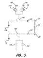
- FIG. 5shows, in accordance with the present systems and methods, the identical electrical stimulation circuit depicted in FIG. 3 , except with one switch bypassing one set of dual current sources, thereby activating the low compliance voltage mode (in a bipolar electrode configuration);
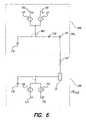
- FIG. 6shows, in accordance with the preset systems and methods, a schematic diagram of an electrical stimulation circuit, comprised of two partial circuits, which electrical stimulation circuit utilizes a push-pull, pair of current sources in high compliance voltage mode and delivers stimulation into a monopolar electrode configuration; and
- FIG. 7shows, in accordance with the present systems and methods, the identical electrical stimulation circuit depicted in FIG. 5 , except with one switch bypassing one set of dual current sources, thereby activating the low compliance voltage mode (in a monopolar electrode configuration).
- Multi-channel stimulatorsare used in various implantable medical devices.
- such multi-channel stimulatorscan be found in spinal cord stimulation devices for treating intractable pain and cochlear devices for restoration of hearing in the profoundly deaf.
- the systems and methods described hereinwill be discussed in the context of use in a cochlear implant device. Details associated with the operation of a typical cochlear implant system may be found in one or more of the following U.S. patents, each of which is incorporated herein by reference: U.S. Pat. Nos. 6,157,861; 6,002,966; 5,824,022; 5,603,726; 5,344,387; and 4,532,930.
- FIG. 1A representative cochlear stimulation system 10 is illustrated in FIG. 1 .
- a microphone 12senses acoustic waves and converts such sensed waves to an electrical signal.
- the electrical signalis then processed in an appropriate manner by a speech processor (SP) 14 .
- SPspeech processor
- Such processingmay include dividing the signal into different frequency bands and generating an appropriate stimulation control signal for each frequency band.
- the stimulation control signal(s)is passed on to an implantable cochlear stimulator (ICS) 16 via a radio-frequency communications link 15 .
- the ICS 16is connected to an electrode array 20 .
- the electrode array 20is inserted into a cochlea 30 . (Note, that the representation of the cochlea 30 shown in FIG. 1 is meant only as a schematic representation.)
- the electrode array 20includes a plurality of spaced-apart electrode contacts 22 thereon. Each electrode contact 22 is electrically connected to the electrical circuitry within the ICS 16 by way of a lead 18 , which lead 18 has a plurality of electrical wire conductors embedded therein as is known in the art.
- the ICSin response to the control signal(s) received from the SP 14 , generates an electrical stimulation current on selected groupings of the electrode contacts 22 .
- the cochlea 30comprises a snail-shaped member having three parallel ducts that spiral around its center bony region, known as the modiolus.
- One of the spiraling parallel ducts within the cochleais the scale tympani.
- the center bony region, or modiolusis where ganglion nerve cells 32 are located. Each of the ganglion cells 32 is coupled to the auditory nerve 40 , which connects to the brain.
- the cochlear stimulation system 10It is the function of the cochlear stimulation system 10 to electrically stimulate the ganglion cells 22 with electrical stimulation current representative of the acoustic waves sensed by the microphone 12 .
- the electrode array 20is inserted into the scale tympani so that the electrode contacts 22 encircle the modiolus and ganglion cells 32 .
- Electrical stimulation currentflows between selected electrode contacts 22 and hence stimulates the ganglion cells 32 near the selected electrode contacts, as controlled by the ICS 16 in accordance with a programmed or selected speech processing strategy.
- the speech processing stretchis defined by the control signals received from the SP 14 .
- the control signalsare modulated by the acoustic waves sensed by the microphone 12 , thereby causing the stimulation current to stimulate appropriate ganglion cells as a function of the sensed acoustic waves. For example, low frequency acoustic waves cause ganglion cells near the apical tip of the cochlea to be stimulated, whereas high frequency acoustic waves cause ganglion cells near the basal region of the cochlea to be stimulated.
- Stimulation of the ganglion cellscan be accomplished using two electrode configuration modes.
- One electrode configuration modeis a “bipolar mode,” which uses two electrode contacts 22 positioned relatively close to each other. In this mode, the load resistance appears between the two electrode contacts 22 . The load resistance is contributed to by the interface between the tissue and electrode contacts 22 and the tissue itself between the electrode contacts.
- Another electrode configurationis a “monopolar mode,” which employs one of the electrode contacts 22 in the electrode array and an indifferent electrode that is relatively distant from the electrode contacts 22 .
- the indifferent electrodecan be the exterior container (the “case”) of the ICS, which container can be made from a biocompatible, electrically conductive metal such as titanium.
- the load resistanceis contributed to by the interface between the electrode contact 22 and tissue, the interface between the indifferent electrode and tissue, and the tissue itself between the electrode contact and the indifferent electrode.
- a uniphasic stimulusprovides current flow in only one direction through an electrode.
- a biphasic stimulusprovides current flows in both directions through an electrode within a relatively short time period. It is thought that uniphasic stimulation may cause charges to accumulate in the tissue near the stimulating electrode and thereby cause injury to this tissue. In addition, it is also believed that uniphasic stimulation can cause premature degradation of the electrodes. Therefore, most conventional multi-channel stimulators, including ones for cochlear stimulators, use some form of biphasic stimulation.
- FIG. 2shows a graph of a biphasic stimulus as a function of time.
- Stimulus pulse waveforms X and Yare individually uniphasic. But considered together, they are biphasic because the flow of stimulation current through an active electrode is in both directions.
- a particular biphasic stimulation in which an equal quantity of electrical charge flows in both directions through an electrodeis termed a “charge-balanced,” biphasic stimulation.
- a charge-balanced stimulationcan be achieved by ensuring that the flow of charge in both directions through a stimulating electrode is equal over time.
- the accumulation of chargeis represented by the area (A) and area (B) above and below the zero current flow line, respectively.
- FIG. 3shows, in accordance with the present systems and methods, a circuit diagram of a portion of a multi-channel stimulator circuit connected to N number of electrodes, E 1 . . . EN, and a case or housing electrode ECASE.
- Each partial circuitdesignated as CIR 1 , CIR 2 , CIR 3 . . . CIRN or CIRCASE, has dual current sources electrically connected to its respective electrode, E 1 , E 2 , E 3 . . . EN or ECASE.
- Partial circuits CIR 1 , CIR 2 , CIR 3 . . . CIRNalso include a D.C. blocking capacitor, 120 , 120 ′ 120 ′′ or 120 ′′′.
- each partial circuithas a bypass switch 160 , 160 ′, 160 ′′, 160 ′′′ or 165 for bypassing dual current sources and, instead, connecting the stimulation circuit to ground 170 (“first closed position”) or electrically connecting the stimulation circuit to the dual current sources (“second closed position”).
- each partial circuit, CIR 1 , CIR 2 , CIR 3 . . . CIRN of a multi channel stimulatoris identical.
- CIRCASEis different because the device case or housing, which may act as an indifferent electrode, generally has a larger surface area than a stimulating electrode and, moreover, does not include a D.C.
- CIRCASEmay be used in combination with one of the partial circuits, CIR 1 , CIR 2 , CIR 3 . . . CIRN, each of which already includes a D.C. blocking capacitor, 120 , 120 ′, 120 ′′ or 120 ′′′, sufficient to prevent delivery of direct current to stimulated tissue.
- a complete stimulation circuitis formed by combining two partial circuits selected form the set CIR 1 , CIR 2 , CIR 3 . . . CIR N and CIR CASE .
- CIR 1 combined with CIR 3forms a bipolar stimulation circuit having two electrodes E 1 and E 3 .
- Another exampleis the combination of CIR 2 and CIR 3 having two electrodes E 2 and E 3 and forming another bipolar stimulation circuit.
- a monopolar, stimulation circuitmay be formed by combining partial circuit, C case , with one of the circuits in the set, CIR 1 , CIR 2 , CIR 3 . . . CIR N .
- the device case or housingfunctions as an indifferent electrode, E case , and one selected electrode among the set, E 1 , E 2 , E 3 . . . E N , acts as the stimulating electrode.
- E casean indifferent electrode
- E 2the device case or housing
- E 3the device case
- E 3the device case
- E Nacts as the stimulating electrode.
- two sets of dual current sourcesare in the stimulation circuit.
- only two current sourcesmay operate at any one time.
- current sources 115 and 110 ′may operate together at one time to produce stimulus current waveform X in FIG. 2 , as measured at E 1 .
- current sources 110 and 115 ′may operate together to produce stimulus current waveform Y in FIG. 2 , as measured at E 1 .
- Such arrangement of paired current sourcesis termed a “push-pull” arrangement.
- FIG. 4shows, in accordance with the present systems and methods, a schematic circuit diagram of a complete simulation circuit which utilizes a push-pull pair of current sources in a high compliance voltage mode. It can be seen that CIR 1 and CIR 2 , shown in FIG. 3 , may be combined together to provide a complete bipolar circuit, as shown in FIG. 4 .
- Rails 105 , 106 and 105 ′, 106 ′provide electrical connection points for a common supply voltage.
- FIG. 4shows, for purposes of illustration, a rail 105 which can be connected to a voltage of V+ relative to ground and rail 106 ′ which can be connected to a voltage of V ⁇ . To provide current flowing in the opposite direction through the stimulation circuit, rail 106 can be connected to a voltage V ⁇ and rail 105 ′ can be connected to a voltage V′.
- electrode contacts 22 and 22 ′may be part of an electrode array, for example, as depicted in FIG. 1 .
- the complete stimulation circuithas two pairs of dual current sources, two D.C. blocking capacitors 120 , 120 ′ and two bypass switches 160 , 160 ′, either of which may be used to bypass dual current sources 115 , 110 or 115 ′, 110 ′ and connect, instead, to ground 170 .
- Resistor 125simplistically represents the load resistance presented by the body tissue between the two electrode contacts 22 and 22 ′.
- the four current sourcesmay be current mode, digital-to-analog converters (DACs).
- Current sources 115 and 110 ′operate together in a “push-pull” arrangement to direct current flow in one (uniphasic) direction through the circuit and through the electrode contacts 22 and 22 ′ such that electrode contact 22 functions as a cathode and electrode contact 22 ′ functions as an anode.
- the pair of current sources 110 and 115 ′operate together to direct current flow in the opposite direction through the stimulation circuit and through the electrode contacts 22 and 22 ′, such that electrode contact 22 ′ is a cathode and electrode contact 22 is an anode.
- current sources 110 and 115 ′are operating only when current sources 115 and 110 ′ are turned off and vice versa.
- a software programmay be used to dynamically turn on and off the push-pull pairs of current sources in timed intervals.
- an interval timermay enable current sources 110 and 115 ′ together in one timed interval, while current sources 115 and 110 ′ are disabled, then, in the next interval, current sources 115 and 110 ′ may be enabled together, while current sources 110 and 115 ′ are disabled, and so on.
- Capacitors 120 and 120 ′are internal, blocking capacitors which function to block direct current. These blocking capacitors prevent the possible occurrence of direct current being applied through electrode contacts 22 and 22 ′ which can harm tissue near these contacts.
- bypass switch 160is in a “second closed” position to connect the stimulation circuit to the dual current sources 110 and 115 .
- bypass switch 160 ′is in a “second closed” position connecting the stimulation circuit to the dual current sources 110 ′ and 115 ′. With the bypass switches 160 and 160 ′ thereby in such positions, the voltage difference or the compliance voltage between rails 105 ′ and 106 is effectively
- Switching the bypass switch 160 ′ between a first, closed position, i.e., connecting the stimulation circuit to ground 170 , and a second, closed position, connecting the stimulation circuit to dual current sources 115 ′ and 110 ′ (while switch 160 remains in a second, closed position, connecting dual current sources 110 and 115 ), as well as enabling and disabling current source pairs, ( 110 , 115 ′) and ( 115 and 110 ′),can be accomplished with appropriate software programmable controls.
- bypass switch 160 ′in a second, closed position, which connects dual current sources 115 ′ and 110 ′ to the stimulation circuit, while bypass switch 160 selects between connecting the stimulation circuit to ground 170 or dual current sources 110 and 115 .
- FIG. 5shows, in accordance with the present systems and methods, an identical circuit diagram as provided in FIG. 4 , except that the stimulation circuit is switched to a low compliance voltage mode.
- the bypass switch 160 ′connects the stimulation circuit to ground 170 and, hence, bypasses the dual current sources 110 ′ and 115 ′, which can be turned off, as they are not needed.
- Bypass switch 160is placed in the second, closed position to permit dual current sources 110 and 115 to be connected to the stimulation circuit.
- the maximum load resistance through which a given Istim is suppliedis also halved.
- a biphasic stimulation with the circuit of FIG. 5may be delivered by applying V ⁇ to rail 106 and enabling current source 115 in one interval, while current source 110 is turned off. This provides a uniphasic, stimulus pulse through electrode contacts 22 and 22 ′ in one circuit direction, for instance, as shown by curve X in FIG. 2 . Then, in the next interval, current source 115 is disabled and, at the same time, current source 110 is enabled, while rail 105 has V+ applied, providing another uniphasic, stimulus pulse but in the opposite direction through the circuit, for example, shown as curve Y in FIG. 2 . These two uniphasic pulses, flowing through the circuit in opposite directions at different times, may be combined to provide a charged-balanced, biphasic stimulation regime.
- FIG. 6shows, in accordance with he present systems and methods, a schematic diagram of an electrical stimulation circuit which uses push-pull, current sources in a high compliance voltage mode.
- the circuitdelivers current stimulation into a monopolar electrode configuration, where electrode 22 is the active electrode and electrode 23 is the indifferent electrode, usually the case or housing of an implantable medical device.
- the complete circuitis a combination of two partial circuits CIR 1 and CIRCASE.
- CIR 1is connected to the electrode contact 22 via a D.C. blocking capacitor 120 .
- Indifferent case electrode 23is connected to either ground 170 or dual current sources 150 and 155 via a bypass switch 165 . As shown, electrode 23 is not connected to a D.C.
- Load resistor 125 ′represents a simplified resistance provided by the tissue between the electrode 22 and indifferent electrode 23 .
- electrode contact 22is near or in contact with the tissue to be stimulated.
- Indifferent electrode 23which is often the medical device case or housing, however, is generally distant from the target tissue and also distant from electrode contact 22 .
- the bypass switch 165is programmed to the second, closed position.
- Current source pair 110 and 150operate together to drive current in one circuit direction, while rail 105 has V+ applied and rail 175 has V ⁇ applied.
- Current source pair 115 and 155work together in a push-pull arrangement to drive current flow in an opposite circuit direction, while rails 106 and 176 have V ⁇ and V+ voltages applied, respectively.
- FIG. 7shows, in accordance with the present systems and methods, the identical circuit of FIG. 6 , except switched to the low compliance voltage mode (V).
- the electrode configurationis once again monopolar with electrode contact 22 and indifferent electrode contact 23 .
- the bypass switch 165is in the first, closed position, thereby bypassing dual current sources 150 and 155 . Because dual current sources 150 and 155 are not being used, they may be turned off.
- bypass switch 160can bypass dual current sources 110 and 115 and connect to ground, while bypass switch 165 connects the stimulation circuit to dual current sources 150 and 155 . This latter circuit configuration would also provide a low compliance voltage, monopolar electrode configuration.
- the voltages at pairs of rails 105 , 106 ′; 106 , 105 ′; 105 , 175 ; and 106 , 176are provided by the common supply voltage.
- Each of the up to N stimulation circuits (channels)can operate independently and be selected to operate between low and high compliance voltages, as previously described.
- the bypass switches 160 and 165may be used to control the compliance mode for each stimulation channel.
- the switches 160 and 165 for each stimulation circuitmay be independently and dynamically controlled by software. Dynamic switching does not require user involvement and this instantaneous adjustment of compliance voltages can further optimize the power consumed by each channel.
- each stimulation channel(or stimulation circuit) may be independently switched to use either low or high compliance modes according to the needs of each stimulation channel.
- the selection of compliance voltage modesmay be automatically stored in long-term memory contained in the stimulator.
- the stimulation threshold data of each stimulation channel (or stimulation circuit)consisting of two electrode contacts or one electrode contact and an indifferent, case electrode may also be stored in memory for later retrieval and used to select whether a stimulation channel should be set to low or high voltage compliance modes.
- Stimulation thresholdsmay differ widely and are a function of differences in the position of an electrode contact relative to the ganglion nerves in the cochlea and to physiological variance in the location of the nerves along the cochlea. Even very slight electrode positional differences can have marked changes in stimulation thresholds.
- the stimulation thresholdsmay be measured in various ways, for example, stimulation current may be applied at the two electrode contacts, e.g., the magnitude of the current (with pulsewidth held constant) may be increased until some indication of nerve firing is noticed or measured.
- threshold stimulationmay be determined by the perception of sound or, alternatively, the stimulator device may have sensors which can detect nerves firing when they are captured by a stimulus that is at or above stimulation threshold. Once such stimulation threshold is obtained for each channel, this threshold information may be kept in memory and later recalled in order to set each channel (or stimulation circuit) to either a low or high voltage compliance modes. The setting of the voltage compliance mode may be done nearly instantaneously, using dynamic switching.
- Each selected channelmay be independently set so that low voltage compliance mode may be used whenever possible.
- the current draw in the low voltage compliance modemay be halved and, thus, energy use can be reduced. Such energy savings may be substantial. Up to a 20 to 25% savings in energy may be achieved, if half of the channels are operated in low voltage compliance mode.
- each channelmay provide uniphasic or biphasic stimulation, and selection of monopolar or bipolar electrode configurations.
- a multi-channel stimulation system for cochlear applicationhas been discussed. It can be appreciated, however, that the present systems and methods may be used with any multi-channel stimulation system having a single common supply voltage and where each channel has a different compliance voltage requirements.
- a spinal cord stimulator for treating intractable paincan have multiple channels and may have a circuit design which utilizes a common power supply. Such a circuit may be amenable to utilizing a dual range compliance voltage as provided by the present systems and methods.
Landscapes
- Health & Medical Sciences (AREA)
- Neurology (AREA)
- Neurosurgery (AREA)
- Engineering & Computer Science (AREA)
- Biomedical Technology (AREA)
- Nuclear Medicine, Radiotherapy & Molecular Imaging (AREA)
- Radiology & Medical Imaging (AREA)
- Life Sciences & Earth Sciences (AREA)
- Animal Behavior & Ethology (AREA)
- General Health & Medical Sciences (AREA)
- Public Health (AREA)
- Veterinary Medicine (AREA)
- Electrotherapy Devices (AREA)
Abstract
Description
Claims (16)
Priority Applications (3)
| Application Number | Priority Date | Filing Date | Title |
|---|---|---|---|
| US10/459,040US7519428B1 (en) | 2002-06-14 | 2003-06-11 | Dual-range compliance voltage supply for a multi-channel stimulator |
| US12/057,891US8116878B1 (en) | 2002-06-14 | 2008-03-28 | Dual-range compliance voltage supply for a multi-channel stimulator |
| US12/057,911US8121703B1 (en) | 2002-06-14 | 2008-03-28 | Dual-range compliance voltage supply for a multi-channel stimulator |
Applications Claiming Priority (2)
| Application Number | Priority Date | Filing Date | Title |
|---|---|---|---|
| US38873102P | 2002-06-14 | 2002-06-14 | |
| US10/459,040US7519428B1 (en) | 2002-06-14 | 2003-06-11 | Dual-range compliance voltage supply for a multi-channel stimulator |
Related Child Applications (2)
| Application Number | Title | Priority Date | Filing Date |
|---|---|---|---|
| US12/057,891DivisionUS8116878B1 (en) | 2002-06-14 | 2008-03-28 | Dual-range compliance voltage supply for a multi-channel stimulator |
| US12/057,911DivisionUS8121703B1 (en) | 2002-06-14 | 2008-03-28 | Dual-range compliance voltage supply for a multi-channel stimulator |
Publications (1)
| Publication Number | Publication Date |
|---|---|
| US7519428B1true US7519428B1 (en) | 2009-04-14 |
Family
ID=40525193
Family Applications (3)
| Application Number | Title | Priority Date | Filing Date |
|---|---|---|---|
| US10/459,040Expired - Fee RelatedUS7519428B1 (en) | 2002-06-14 | 2003-06-11 | Dual-range compliance voltage supply for a multi-channel stimulator |
| US12/057,891Expired - Fee RelatedUS8116878B1 (en) | 2002-06-14 | 2008-03-28 | Dual-range compliance voltage supply for a multi-channel stimulator |
| US12/057,911Expired - Fee RelatedUS8121703B1 (en) | 2002-06-14 | 2008-03-28 | Dual-range compliance voltage supply for a multi-channel stimulator |
Family Applications After (2)
| Application Number | Title | Priority Date | Filing Date |
|---|---|---|---|
| US12/057,891Expired - Fee RelatedUS8116878B1 (en) | 2002-06-14 | 2008-03-28 | Dual-range compliance voltage supply for a multi-channel stimulator |
| US12/057,911Expired - Fee RelatedUS8121703B1 (en) | 2002-06-14 | 2008-03-28 | Dual-range compliance voltage supply for a multi-channel stimulator |
Country Status (1)
| Country | Link |
|---|---|
| US (3) | US7519428B1 (en) |
Cited By (22)
| Publication number | Priority date | Publication date | Assignee | Title |
|---|---|---|---|---|
| US20060195159A1 (en)* | 2004-12-03 | 2006-08-31 | Kerry Bradley | System and method for choosing electrodes in an implanted stimulator device |
| US20100114260A1 (en)* | 2008-10-31 | 2010-05-06 | Medtronic, Inc. | Implantable therapeutic nerve stimulator |
| US20100211132A1 (en)* | 2009-02-17 | 2010-08-19 | Boston Scientific Neuromodulation Corporation | Selectable Boost Converter and Charge Pump for Compliance Voltage Generation in an Implantable Stimulator Device |
| WO2011039562A1 (en)* | 2009-09-29 | 2011-04-07 | Yeditepe Universitesi | Power management techniques for implanted stimulators |
| US20110093042A1 (en)* | 2009-10-21 | 2011-04-21 | Medtronic, Inc. | Stimulation with utilization of case electrode |
| US20110093043A1 (en)* | 2009-10-21 | 2011-04-21 | Medtronic, Inc. | Programming techniques for stimulation with utilization of case electrode |
| US20110093030A1 (en)* | 2009-10-21 | 2011-04-21 | Medtronic, Inc. | Managing electrical stimulation therapy based on variable electrode combinations |
| US20110125214A1 (en)* | 2009-11-25 | 2011-05-26 | Medtronic, Inc. | Medical electrical stimulation with external simulated case electrode |
| US8116878B1 (en)* | 2002-06-14 | 2012-02-14 | Advanced Bionics | Dual-range compliance voltage supply for a multi-channel stimulator |
| WO2012061608A3 (en)* | 2010-11-03 | 2012-07-19 | The Cleveland Clinic Foundation | Apparatus for energy efficient stimulation |
| US8560080B2 (en) | 2010-06-11 | 2013-10-15 | Medtronic, Inc. | Programming techniques for controlling rate of change of electrical stimulation therapy |
| US20140052207A1 (en)* | 2012-08-16 | 2014-02-20 | Cardiac Pacemakers, Inc. | Therapy delivery architecture for implantable medical device |
| US9020589B2 (en) | 2010-04-27 | 2015-04-28 | Medtronic, Inc. | Electrical stimulator with voltage mode emulation using regulated current |
| US9320901B2 (en) | 2010-04-28 | 2016-04-26 | Medtronic, Inc. | Stimulation with utilization of non-selected electrode |
| EP2519318B1 (en)* | 2009-12-29 | 2018-02-14 | Advanced Bionics AG | Dynamic compliance voltage management for an implantable stimulator |
| US9987493B2 (en) | 2008-10-28 | 2018-06-05 | Medtronic, Inc. | Medical devices and methods for delivery of current-based electrical stimulation therapy |
| WO2021102448A1 (en) | 2019-11-24 | 2021-05-27 | Presidio Medical, Inc. | Pulse generation and stimulation engine systems |
| WO2022154758A1 (en) | 2021-01-13 | 2022-07-21 | Orta Dogu Teknik Universitesi | Powering system for constant current neural stimulators |
| US11413461B2 (en) | 2019-11-25 | 2022-08-16 | Medtronic, Inc. | Independent control of electrical stimulation amplitude for electrodes for delivery of electrical stimulation therapy |
| CN117258147A (en)* | 2023-09-26 | 2023-12-22 | 电子科技大学 | Current mode nerve stimulator applied to implantable bidirectional brain-computer interface |
| US12109418B2 (en) | 2020-11-25 | 2024-10-08 | Medtronic, Inc. | Segmented lead independent electrode control for sensing or adaptive stimulation |
| US12383745B2 (en) | 2019-09-06 | 2025-08-12 | Boston Scientific Neuromodulation Corporation | Management of compliance voltage for a stimulator device |
Families Citing this family (17)
| Publication number | Priority date | Publication date | Assignee | Title |
|---|---|---|---|---|
| US8311639B2 (en) | 2009-07-08 | 2012-11-13 | Nevro Corporation | Systems and methods for adjusting electrical therapy based on impedance changes |
| CA3051810A1 (en) | 2009-02-10 | 2010-08-19 | Nevro Corporation | Systems and methods for delivering neural therapy correlated with patient status |
| US8498710B2 (en) | 2009-07-28 | 2013-07-30 | Nevro Corporation | Linked area parameter adjustment for spinal cord stimulation and associated systems and methods |
| US9814884B2 (en) | 2011-11-04 | 2017-11-14 | Nevro Corp. | Systems and methods for detecting faults and/or adjusting electrical therapy based on impedance changes |
| US9295840B1 (en) | 2013-01-22 | 2016-03-29 | Nevro Corporation | Systems and methods for automatically programming patient therapy devices |
| US9895538B1 (en) | 2013-01-22 | 2018-02-20 | Nevro Corp. | Systems and methods for deploying patient therapy devices |
| US9731133B1 (en) | 2013-01-22 | 2017-08-15 | Nevro Corp. | Systems and methods for systematically testing a plurality of therapy programs in patient therapy devices |
| EP2790470B1 (en) | 2013-04-08 | 2018-03-21 | Dialog Semiconductor GmbH | Programmable current source with optimized compliance region for efficient backlighting in portable applications |
| US9517344B1 (en) | 2015-03-13 | 2016-12-13 | Nevro Corporation | Systems and methods for selecting low-power, effective signal delivery parameters for an implanted pulse generator |
| US10300277B1 (en) | 2015-12-14 | 2019-05-28 | Nevro Corp. | Variable amplitude signals for neurological therapy, and associated systems and methods |
| WO2017125274A1 (en)* | 2016-01-20 | 2017-07-27 | Sorin Crm Sas | Active implantable medical neurostimulation device with sectoral electrodes that are switchable according to various configurations |
| EP3606599A4 (en) | 2017-04-03 | 2021-01-13 | Presidio Medical, Inc. | Systems and methods for direct current nerve conduction block |
| CN119607410A (en) | 2018-02-20 | 2025-03-14 | 普雷西迪奥医学有限公司 | Methods and systems for nerve conduction blockade |
| US11752329B2 (en) | 2018-07-01 | 2023-09-12 | Presidio Medical, Inc. | Systems and methods for nerve conduction block |
| CA3159295A1 (en) | 2019-11-24 | 2021-05-27 | Douglas Michael Ackermann | Current bias as a control mechanism for electrode operation |
| EP4346997A4 (en)* | 2021-05-26 | 2025-04-02 | Presidio Medical, Inc. | PULSE GENERATION AND STIMULATION MOTOR SYSTEMS |
| WO2022251520A1 (en)* | 2021-05-26 | 2022-12-01 | Presidio Medical, Inc. | Acute blockade with delayed neural suppression |
Citations (25)
| Publication number | Priority date | Publication date | Assignee | Title |
|---|---|---|---|---|
| US4532930A (en) | 1983-04-11 | 1985-08-06 | Commonwealth Of Australia, Dept. Of Science & Technology | Cochlear implant system for an auditory prosthesis |
| US4592359A (en)* | 1985-04-02 | 1986-06-03 | The Board Of Trustees Of The Leland Stanford Junior University | Multi-channel implantable neural stimulator |
| US4931795A (en) | 1989-08-09 | 1990-06-05 | Alfred E. Mann Foundation | Digital to analog signal converter |
| US4990845A (en) | 1989-12-18 | 1991-02-05 | Alfred E. Mann Foundation For Scientific Research | Floating current source |
| US5271397A (en)* | 1989-09-08 | 1993-12-21 | Cochlear Pty. Ltd. | Multi-peak speech processor |
| US5344387A (en) | 1992-12-23 | 1994-09-06 | Lupin Alan J | Cochlear implant |
| US5522865A (en) | 1989-09-22 | 1996-06-04 | Alfred E. Mann Foundation For Scientific Research | Voltage/current control system for a human tissue stimulator |
| US5531774A (en) | 1989-09-22 | 1996-07-02 | Alfred E. Mann Foundation For Scientific Research | Multichannel implantable cochlear stimulator having programmable bipolar, monopolar or multipolar electrode configurations |
| US5601617A (en) | 1995-04-26 | 1997-02-11 | Advanced Bionics Corporation | Multichannel cochlear prosthesis with flexible control of stimulus waveforms |
| US5603726A (en) | 1989-09-22 | 1997-02-18 | Alfred E. Mann Foundation For Scientific Research | Multichannel cochlear implant system including wearable speech processor |
| US5755747A (en)* | 1995-12-19 | 1998-05-26 | Daly; Christopher | Cochlear implant system with soft turn on electrodes |
| US5824022A (en) | 1996-03-07 | 1998-10-20 | Advanced Bionics Corporation | Cochlear stimulation system employing behind-the-ear speech processor with remote control |
| US5876425A (en) | 1989-09-22 | 1999-03-02 | Advanced Bionics Corporation | Power control loop for implantable tissue stimulator |
| US5909348A (en)* | 1995-06-01 | 1999-06-01 | Itt Manufacturing Enterprises, Inc. | Fault current recognition circuitry |
| US5917346A (en) | 1997-09-12 | 1999-06-29 | Alfred E. Mann Foundation | Low power current to frequency converter circuit for use in implantable sensors |
| US5938691A (en) | 1989-09-22 | 1999-08-17 | Alfred E. Mann Foundation | Multichannel implantable cochlear stimulator |
| US5999848A (en) | 1997-09-12 | 1999-12-07 | Alfred E. Mann Foundation | Daisy chainable sensors and stimulators for implantation in living tissue |
| US6035237A (en)* | 1995-05-23 | 2000-03-07 | Alfred E. Mann Foundation | Implantable stimulator that prevents DC current flow without the use of discrete output coupling capacitors |
| US6157861A (en) | 1996-06-20 | 2000-12-05 | Advanced Bionics Corporation | Self-adjusting cochlear implant system and method for fitting same |
| US6175767B1 (en)* | 1998-04-01 | 2001-01-16 | James H. Doyle, Sr. | Multichannel implantable inner ear stimulator |
| US6181969B1 (en)* | 1998-06-26 | 2001-01-30 | Advanced Bionics Corporation | Programmable current output stimulus stage for implantable device |
| WO2001008282A1 (en) | 1999-07-27 | 2001-02-01 | Alfred E. Mann Foundation | Voltage control circuitry for charging output capacitor |
| US6219580B1 (en)* | 1995-04-26 | 2001-04-17 | Advanced Bionics Corporation | Multichannel cochlear prosthesis with flexible control of stimulus waveforms |
| US6516227B1 (en)* | 1999-07-27 | 2003-02-04 | Advanced Bionics Corporation | Rechargeable spinal cord stimulator system |
| US20050085873A1 (en) | 2003-10-17 | 2005-04-21 | Gord John C. | Method and apparatus for efficient power/data transmission |
Family Cites Families (1)
| Publication number | Priority date | Publication date | Assignee | Title |
|---|---|---|---|---|
| US7519428B1 (en)* | 2002-06-14 | 2009-04-14 | Advanced Bionics, Llc | Dual-range compliance voltage supply for a multi-channel stimulator |
- 2003
- 2003-06-11USUS10/459,040patent/US7519428B1/ennot_activeExpired - Fee Related
- 2008
- 2008-03-28USUS12/057,891patent/US8116878B1/ennot_activeExpired - Fee Related
- 2008-03-28USUS12/057,911patent/US8121703B1/ennot_activeExpired - Fee Related
Patent Citations (28)
| Publication number | Priority date | Publication date | Assignee | Title |
|---|---|---|---|---|
| US4532930A (en) | 1983-04-11 | 1985-08-06 | Commonwealth Of Australia, Dept. Of Science & Technology | Cochlear implant system for an auditory prosthesis |
| US4592359A (en)* | 1985-04-02 | 1986-06-03 | The Board Of Trustees Of The Leland Stanford Junior University | Multi-channel implantable neural stimulator |
| US4931795A (en) | 1989-08-09 | 1990-06-05 | Alfred E. Mann Foundation | Digital to analog signal converter |
| US5271397A (en)* | 1989-09-08 | 1993-12-21 | Cochlear Pty. Ltd. | Multi-peak speech processor |
| US5876425A (en) | 1989-09-22 | 1999-03-02 | Advanced Bionics Corporation | Power control loop for implantable tissue stimulator |
| US5522865A (en) | 1989-09-22 | 1996-06-04 | Alfred E. Mann Foundation For Scientific Research | Voltage/current control system for a human tissue stimulator |
| US5531774A (en) | 1989-09-22 | 1996-07-02 | Alfred E. Mann Foundation For Scientific Research | Multichannel implantable cochlear stimulator having programmable bipolar, monopolar or multipolar electrode configurations |
| US5938691A (en) | 1989-09-22 | 1999-08-17 | Alfred E. Mann Foundation | Multichannel implantable cochlear stimulator |
| US5603726A (en) | 1989-09-22 | 1997-02-18 | Alfred E. Mann Foundation For Scientific Research | Multichannel cochlear implant system including wearable speech processor |
| US5776172A (en) | 1989-09-22 | 1998-07-07 | Alfred E. Mann Foundation For Scientific Research | Multichannel implantable cochlear stimulator |
| US4990845A (en) | 1989-12-18 | 1991-02-05 | Alfred E. Mann Foundation For Scientific Research | Floating current source |
| US5344387A (en) | 1992-12-23 | 1994-09-06 | Lupin Alan J | Cochlear implant |
| US5601617A (en) | 1995-04-26 | 1997-02-11 | Advanced Bionics Corporation | Multichannel cochlear prosthesis with flexible control of stimulus waveforms |
| US6219580B1 (en)* | 1995-04-26 | 2001-04-17 | Advanced Bionics Corporation | Multichannel cochlear prosthesis with flexible control of stimulus waveforms |
| US6002966A (en) | 1995-04-26 | 1999-12-14 | Advanced Bionics Corporation | Multichannel cochlear prosthesis with flexible control of stimulus waveforms |
| US6035237A (en)* | 1995-05-23 | 2000-03-07 | Alfred E. Mann Foundation | Implantable stimulator that prevents DC current flow without the use of discrete output coupling capacitors |
| US5909348A (en)* | 1995-06-01 | 1999-06-01 | Itt Manufacturing Enterprises, Inc. | Fault current recognition circuitry |
| US5755747A (en)* | 1995-12-19 | 1998-05-26 | Daly; Christopher | Cochlear implant system with soft turn on electrodes |
| US5824022A (en) | 1996-03-07 | 1998-10-20 | Advanced Bionics Corporation | Cochlear stimulation system employing behind-the-ear speech processor with remote control |
| US6157861A (en) | 1996-06-20 | 2000-12-05 | Advanced Bionics Corporation | Self-adjusting cochlear implant system and method for fitting same |
| US5999848A (en) | 1997-09-12 | 1999-12-07 | Alfred E. Mann Foundation | Daisy chainable sensors and stimulators for implantation in living tissue |
| US5917346A (en) | 1997-09-12 | 1999-06-29 | Alfred E. Mann Foundation | Low power current to frequency converter circuit for use in implantable sensors |
| US6175767B1 (en)* | 1998-04-01 | 2001-01-16 | James H. Doyle, Sr. | Multichannel implantable inner ear stimulator |
| US6181969B1 (en)* | 1998-06-26 | 2001-01-30 | Advanced Bionics Corporation | Programmable current output stimulus stage for implantable device |
| WO2001008282A1 (en) | 1999-07-27 | 2001-02-01 | Alfred E. Mann Foundation | Voltage control circuitry for charging output capacitor |
| US6516227B1 (en)* | 1999-07-27 | 2003-02-04 | Advanced Bionics Corporation | Rechargeable spinal cord stimulator system |
| US6799070B2 (en) | 1999-07-27 | 2004-09-28 | The Alfred E. Mann Foundation For Scientific Research | Voltage control circuitry for charging ouput capacitor |
| US20050085873A1 (en) | 2003-10-17 | 2005-04-21 | Gord John C. | Method and apparatus for efficient power/data transmission |
Cited By (44)
| Publication number | Priority date | Publication date | Assignee | Title |
|---|---|---|---|---|
| US8121703B1 (en)* | 2002-06-14 | 2012-02-21 | Advanced Bionics | Dual-range compliance voltage supply for a multi-channel stimulator |
| US8116878B1 (en)* | 2002-06-14 | 2012-02-14 | Advanced Bionics | Dual-range compliance voltage supply for a multi-channel stimulator |
| US10537741B2 (en)* | 2004-12-03 | 2020-01-21 | Boston Scientific Neuromodulation Corporation | System and method for choosing electrodes in an implanted stimulator device |
| US20060195159A1 (en)* | 2004-12-03 | 2006-08-31 | Kerry Bradley | System and method for choosing electrodes in an implanted stimulator device |
| US9987493B2 (en) | 2008-10-28 | 2018-06-05 | Medtronic, Inc. | Medical devices and methods for delivery of current-based electrical stimulation therapy |
| US20100114260A1 (en)* | 2008-10-31 | 2010-05-06 | Medtronic, Inc. | Implantable therapeutic nerve stimulator |
| US8612020B2 (en) | 2008-10-31 | 2013-12-17 | Medtronic, Inc. | Implantable therapeutic nerve stimulator |
| US10391324B2 (en) | 2009-02-17 | 2019-08-27 | Boston Scientific Neuromodulation Corporation | Selectable boost converter and charge pump for compliance voltage generation in an implantable stimulator device |
| US9872995B2 (en) | 2009-02-17 | 2018-01-23 | Boston Scientific Neuromodulation Corporation | Selectable boost converter and charge pump for compliance voltage generation in an implantable stimulator device |
| US9233254B2 (en) | 2009-02-17 | 2016-01-12 | Boston Scientific Neuromodulation Corporation | Selectable boost converter and charge pump for compliance voltage generation in an implantable stimulator device |
| US20100211132A1 (en)* | 2009-02-17 | 2010-08-19 | Boston Scientific Neuromodulation Corporation | Selectable Boost Converter and Charge Pump for Compliance Voltage Generation in an Implantable Stimulator Device |
| US8560081B2 (en) | 2009-09-29 | 2013-10-15 | Yeditepe Universitesi | Power management techniques for implanted stimulators |
| WO2011039562A1 (en)* | 2009-09-29 | 2011-04-07 | Yeditepe Universitesi | Power management techniques for implanted stimulators |
| AU2009353550B2 (en)* | 2009-09-29 | 2015-01-29 | Yeditepe Universitesi | Power management techniques for implanted stimulators |
| US8996123B2 (en) | 2009-10-21 | 2015-03-31 | Medtronic, Inc. | Managing electrical stimulation therapy based on variable electrode combinations |
| US20110093042A1 (en)* | 2009-10-21 | 2011-04-21 | Medtronic, Inc. | Stimulation with utilization of case electrode |
| US20110093030A1 (en)* | 2009-10-21 | 2011-04-21 | Medtronic, Inc. | Managing electrical stimulation therapy based on variable electrode combinations |
| US8571677B2 (en) | 2009-10-21 | 2013-10-29 | Medtronic, Inc. | Programming techniques for stimulation with utilization of case electrode |
| US20110093043A1 (en)* | 2009-10-21 | 2011-04-21 | Medtronic, Inc. | Programming techniques for stimulation with utilization of case electrode |
| US8538538B2 (en) | 2009-11-25 | 2013-09-17 | Medtronic, Inc. | Medical electrical stimulation with implantable simulated case electrode |
| US20110125214A1 (en)* | 2009-11-25 | 2011-05-26 | Medtronic, Inc. | Medical electrical stimulation with external simulated case electrode |
| US8543202B2 (en) | 2009-11-25 | 2013-09-24 | Steven M. Goetz | Medical electrical stimulation with external simulated case electrode |
| US20110125215A1 (en)* | 2009-11-25 | 2011-05-26 | Medtronic, Inc. | Medical electrical stimulation with implantable simulated case electrode |
| EP2519318B1 (en)* | 2009-12-29 | 2018-02-14 | Advanced Bionics AG | Dynamic compliance voltage management for an implantable stimulator |
| US9020589B2 (en) | 2010-04-27 | 2015-04-28 | Medtronic, Inc. | Electrical stimulator with voltage mode emulation using regulated current |
| US9259578B2 (en) | 2010-04-27 | 2016-02-16 | Medtronic, Inc. | Electrical stimulator with voltage mode emulation using regulated current |
| US9320901B2 (en) | 2010-04-28 | 2016-04-26 | Medtronic, Inc. | Stimulation with utilization of non-selected electrode |
| US8560080B2 (en) | 2010-06-11 | 2013-10-15 | Medtronic, Inc. | Programming techniques for controlling rate of change of electrical stimulation therapy |
| WO2012061608A3 (en)* | 2010-11-03 | 2012-07-19 | The Cleveland Clinic Foundation | Apparatus for energy efficient stimulation |
| US9014813B2 (en)* | 2010-11-03 | 2015-04-21 | Cleveland Clinic Foundation | Apparatus for energy efficient stimulation |
| US20120239108A1 (en)* | 2010-11-03 | 2012-09-20 | The Cleveland Clinic Foundation | Apparatus for energy efficient stimulation |
| US9421385B2 (en)* | 2012-08-16 | 2016-08-23 | Cardiac Pacemakers, Inc. | Therapy delivery architecture for implantable medical device |
| WO2014028162A1 (en)* | 2012-08-16 | 2014-02-20 | Cardiac Pacemakers, Inc. | Therapy delivery architecture for implantable medical device |
| US20140052207A1 (en)* | 2012-08-16 | 2014-02-20 | Cardiac Pacemakers, Inc. | Therapy delivery architecture for implantable medical device |
| US12383745B2 (en) | 2019-09-06 | 2025-08-12 | Boston Scientific Neuromodulation Corporation | Management of compliance voltage for a stimulator device |
| JP2023502505A (en)* | 2019-11-24 | 2023-01-24 | プレシディオ・メディカル・インコーポレイテッド | Pulse generation and stimulation engine system |
| US20220409905A1 (en)* | 2019-11-24 | 2022-12-29 | Presidio Medical, Inc. | Pulse generation and stimulation engine systems |
| US11730964B2 (en)* | 2019-11-24 | 2023-08-22 | Presidio Medical, Inc. | Pulse generation and stimulation engine systems |
| EP4061476A4 (en)* | 2019-11-24 | 2023-12-13 | Presidio Medical, Inc. | Pulse generation and stimulation engine systems |
| WO2021102448A1 (en) | 2019-11-24 | 2021-05-27 | Presidio Medical, Inc. | Pulse generation and stimulation engine systems |
| US11413461B2 (en) | 2019-11-25 | 2022-08-16 | Medtronic, Inc. | Independent control of electrical stimulation amplitude for electrodes for delivery of electrical stimulation therapy |
| US12109418B2 (en) | 2020-11-25 | 2024-10-08 | Medtronic, Inc. | Segmented lead independent electrode control for sensing or adaptive stimulation |
| WO2022154758A1 (en) | 2021-01-13 | 2022-07-21 | Orta Dogu Teknik Universitesi | Powering system for constant current neural stimulators |
| CN117258147A (en)* | 2023-09-26 | 2023-12-22 | 电子科技大学 | Current mode nerve stimulator applied to implantable bidirectional brain-computer interface |
Also Published As
| Publication number | Publication date |
|---|---|
| US8116878B1 (en) | 2012-02-14 |
| US8121703B1 (en) | 2012-02-21 |
Similar Documents
| Publication | Publication Date | Title |
|---|---|---|
| US7519428B1 (en) | Dual-range compliance voltage supply for a multi-channel stimulator | |
| US10744318B2 (en) | Current output architecture for an implantable stimulator device | |
| US10940317B2 (en) | System and method of adjusting the compliance voltage in a neuromodulation device | |
| US9320899B2 (en) | Low power loss current digital-to-analog converter used in an implantable pulse generator | |
| US9913975B2 (en) | Neurostimulation system and method for compounding current to minimize current sources | |
| US8175719B2 (en) | Techniques for sensing and adjusting a compliance voltage in an implantable stimulator device | |
| JP5443989B2 (en) | Multi-electrode implantable stimulator with a single current path decoupling capacitor | |
| WO2005101660A1 (en) | Voltage limited systems and methods | |
| JP2015509817A (en) | Field-enhanced current steering using a voltage source | |
| US20110125224A1 (en) | Neurostimulation system and method for combining current using reconfigurable current sources | |
| KR102557821B1 (en) | Switched capacitor-based electrical stimulation device and method |
Legal Events
| Date | Code | Title | Description |
|---|---|---|---|
| AS | Assignment | Owner name:BOSTON SCIENTIFIC NEUROMODULATION CORPORATION, CAL Free format text:CHANGE OF NAME;ASSIGNOR:ADVANCED BIONICS CORPORATION;REEL/FRAME:020296/0477 Effective date:20071116 Owner name:BOSTON SCIENTIFIC NEUROMODULATION CORPORATION, CALIFORNIA Free format text:CHANGE OF NAME;ASSIGNOR:ADVANCED BIONICS CORPORATION;REEL/FRAME:020296/0477 Effective date:20071116 Owner name:BOSTON SCIENTIFIC NEUROMODULATION CORPORATION,CALI Free format text:CHANGE OF NAME;ASSIGNOR:ADVANCED BIONICS CORPORATION;REEL/FRAME:020296/0477 Effective date:20071116 | |
| AS | Assignment | Owner name:ADVANCED BIONICS, LLC, CALIFORNIA Free format text:ASSIGNMENT OF ASSIGNORS INTEREST;ASSIGNOR:BOSTON SCIENTIFIC NEUROMODULATION CORPORATION;REEL/FRAME:020340/0713 Effective date:20080107 Owner name:ADVANCED BIONICS, LLC,CALIFORNIA Free format text:ASSIGNMENT OF ASSIGNORS INTEREST;ASSIGNOR:BOSTON SCIENTIFIC NEUROMODULATION CORPORATION;REEL/FRAME:020340/0713 Effective date:20080107 | |
| FPAY | Fee payment | Year of fee payment:4 | |
| REMI | Maintenance fee reminder mailed | ||
| LAPS | Lapse for failure to pay maintenance fees | ||
| STCH | Information on status: patent discontinuation | Free format text:PATENT EXPIRED DUE TO NONPAYMENT OF MAINTENANCE FEES UNDER 37 CFR 1.362 | |
| FP | Expired due to failure to pay maintenance fee | Effective date:20170414 | |
| AS | Assignment | Owner name:ADVANCED BIONICS AG, SWITZERLAND Free format text:ASSIGNMENT OF ASSIGNORS INTEREST;ASSIGNOR:ADVANCED BIONICS, LLC;REEL/FRAME:050806/0005 Effective date:20111130 |