US7518952B1 - Sonar sensor array signal distribution system and method - Google Patents
Sonar sensor array signal distribution system and methodDownload PDFInfo
- Publication number
- US7518952B1 US7518952B1US11/517,662US51766206AUS7518952B1US 7518952 B1US7518952 B1US 7518952B1US 51766206 AUS51766206 AUS 51766206AUS 7518952 B1US7518952 B1US 7518952B1
- Authority
- US
- United States
- Prior art keywords
- transmission line
- coaxial transmission
- coupled
- signal
- electromagnetic wave
- Prior art date
- Legal status (The legal status is an assumption and is not a legal conclusion. Google has not performed a legal analysis and makes no representation as to the accuracy of the status listed.)
- Active, expires
Links
- 238000000034methodMethods0.000titleclaimsabstractdescription24
- 230000005540biological transmissionEffects0.000claimsabstractdescription98
- 239000004020conductorSubstances0.000claimsabstractdescription42
- 238000010168coupling processMethods0.000claimsabstractdescription31
- 238000005859coupling reactionMethods0.000claimsabstractdescription31
- 230000008878couplingEffects0.000claimsabstractdescription28
- 230000001902propagating effectEffects0.000claimsabstractdescription15
- 239000000523sampleSubstances0.000claimsdescription30
- 238000000605extractionMethods0.000claimsdescription12
- 238000002347injectionMethods0.000claimsdescription9
- 239000007924injectionSubstances0.000claimsdescription9
- 230000005672electromagnetic fieldEffects0.000claimsdescription4
- 238000007789sealingMethods0.000claimsdescription4
- 230000035515penetrationEffects0.000claimsdescription3
- 230000000644propagated effectEffects0.000abstractdescription2
- 230000008901benefitEffects0.000description10
- 238000009434installationMethods0.000description9
- 238000003491arrayMethods0.000description5
- 238000010586diagramMethods0.000description4
- 230000001939inductive effectEffects0.000description4
- 238000003780insertionMethods0.000description4
- 230000037431insertionEffects0.000description4
- 230000005684electric fieldEffects0.000description3
- 239000002184metalSubstances0.000description3
- 238000012986modificationMethods0.000description3
- 230000004048modificationEffects0.000description3
- XLYOFNOQVPJJNP-UHFFFAOYSA-NwaterSubstancesOXLYOFNOQVPJJNP-UHFFFAOYSA-N0.000description3
- 238000004891communicationMethods0.000description2
- 239000004593EpoxySubstances0.000description1
- 230000002411adverseEffects0.000description1
- 230000004075alterationEffects0.000description1
- 238000006243chemical reactionMethods0.000description1
- 239000003989dielectric materialSubstances0.000description1
- 239000000284extractSubstances0.000description1
- 238000001914filtrationMethods0.000description1
- 239000003292glueSubstances0.000description1
- 238000002955isolationMethods0.000description1
- 238000012423maintenanceMethods0.000description1
- 238000012544monitoring processMethods0.000description1
- 238000011084recoveryMethods0.000description1
- 230000035945sensitivityEffects0.000description1
- 238000000926separation methodMethods0.000description1
- 238000005476solderingMethods0.000description1
Images
Classifications
- H—ELECTRICITY
- H04—ELECTRIC COMMUNICATION TECHNIQUE
- H04B—TRANSMISSION
- H04B3/00—Line transmission systems
- H04B3/52—Systems for transmission between fixed stations via waveguides
Definitions
- the present inventionrelates generally to devices for sonar sensor arrays. More particularly, the present invention relates to a system and method of signal distribution for a sonar sensor array.
- Sonar systemsare used on a variety of platforms including submarines, surface ships, sonobuoys, ground vehicles, aircraft, and shore stations. Sonar arrays use a large number of hydrophones to provide improved sensitivity and directional resolution. Sophisticated sonar arrays may include hundreds of individual hydrophones. These hydrophones are placed in the water and attached or towed behind the platform. Typically, a vast array of cables and connectors are used to electrically connect the hydrophones to the platform employing the sonar. For example, a separate cable from each hydrophone to the sonar equipment is often included to allow the individual signals from each hydrophone to be processed by the sonar equipment for electronic beam forming or source direction estimation.
- a large sonar array having hundreds of sensorsmay include thousands of connectors and millions of feet of cable.
- the arraymay be mounted on the submarine hull and use hundreds of hull penetrators. Failures in the water tightness of these components can adversely affect the reliability of the sonar array and even threaten the integrity of the submarine.
- Interconnection complexitynot only results in high costs for acquisition and installation of a sonar array, but adds ongoing costs for maintenance of the system. For very large sonar arrays, for example having thousands of hydrophones, the interconnection complexity and cost is an obstacle to deploying such large arrays.
- a signal distribution systemin one embodiment, includes a coaxial transmission line.
- a plurality of tapsis affixed to an outer conductor of the coaxial transmission line along a length of the coaxial transmission line.
- Each of the tapshas at least one field coupling portion extending through an opening in the outer conductor into an internal field region of the coaxial transmission line.
- the tapsinterface with electromagnetic wave energy propagating within the coaxial transmission line.
- Additional embodiments of the present inventioninclude a method of installing a sonar array on a platform and a method of distributing signals within a sonar array.
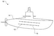
- FIG. 1is a side perspective illustration of a platform having a sonar sensor array system in accordance with an embodiment of the present invention
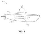
- FIG. 2( a )is a side cross-sectional view of a signal distribution system for a sonar sensor array in accordance with an embodiment of the present invention
- FIG. 2( b )is a top view of the signal distribution system of FIG. 2( a );
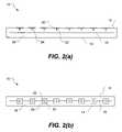
- FIG. 3is a side cross-sectional view showing detail of tap for a signal distribution system in accordance with an embodiment of the present invention
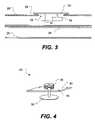
- FIG. 4is a side perspective view of a capacitively-coupled tap in accordance with an embodiment of the present invention.
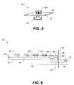
- FIG. 5is a side perspective view of an inductively-coupled tap in accordance with an embodiment of the present invention.
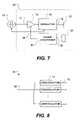
- FIG. 6is a side view of a signal distribution system in accordance with an embodiment of the present invention.
- FIG. 7is a block diagram of an exemplary tap of the signal distribution system of FIG. 6 ;
- FIG. 8is a block diagram of the receiver portion of the signal distribution system of FIG. 6 ;
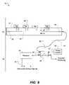
- FIG. 9is a schematic diagram of a signal distribution system in accordance with another embodiment of the present invention.
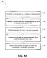
- FIG. 10is a flow chart of a method of installing a sonar array on a platform in accordance with an embodiment of the present invention.
- FIG. 1illustrates a sonar array system, shown generally at 10 , installed on a platform 11 (illustrated here as a submarine) having an array of sensors 13 (e.g. sonar hydrophones) mounted thereto and interfaced to the signal distribution system 15 .
- the signal distribution systemincludes a confinement means for confining a transverse electric and magnetic (TEM) mode electromagnetic wave within a watertight, elongate wave-propagating region.
- TEMtransverse electric and magnetic
- the confinement meanscan be provided by a coaxial transmission line 12 , having an outer conductor 14 and an inner conductor 16 separated by an internal field region 18 .
- the confinement means(e.g., coaxial transmission line 12 ) further includes plural means for interfacing to the elongate wave-propagating region and coupling to at least one electromagnetic wave therein.
- the interfacing meanscan be a tap 20 affixed to the outer conductor 14 of the coaxial transmission line 12 .
- the tapcan include a field coupling portion 22 extending through an opening 24 in the outer conductor into the internal field region of the coaxial transmission line.
- the field coupling portioncan provide for injecting a data-signal carrying electromagnetic wave into the coaxial transmission line.
- the field coupling portioncan also provide for extracting electrical power from an electromagnetic wave propagating in the coaxial transmission.
- the field coupling portioncan be excited by an applied voltage or current to inject a propagating electromagnetic wave into the internal field region as described further below.
- the field coupling portioncan be excited by an electromagnetic wave propagating within the internal field region and a voltage or current extracted as described further below.
- FIG. 3illustrates a detailed illustration of one embodiment of a tap 20 installed in a coaxial transmission line.
- the tapextends through an opening 24 in a water tight outer conductor 26 of the coaxial transmission.
- the coaxial transmission linecan be formed using a rigid metal outer conductor to which the tap is affixed using screws or rivets. A rigid metal conductor can prove helpful in maintaining watertight integrity for deep sea submersible platforms.
- An insulated wire 30can be included inside the metal outer conductor to form a TEM mode transmission line.
- a waveguidesuch as WR-90 can be converted into a TEM mode transmission line by insertion of an internal conductor.
- a seal 28such as a gasket, o-ring, or the like, can be provided between the tap and the watertight outer conductor to maintain the watertight integrity of the coaxial transmission line.
- glue, epoxy, a welded connection, or other combinationscan be used with or in place of the seal to affix the tap to the coaxial transmission line and provide a watertight connection between the tap and the outer conductor.
- the internal field region 18may be filled with a dielectric, air or gas.
- the tap 20can include one or more field coupling portions, such as a capacitively-coupled probe 32 , an inductively coupled probe 34 , or both. Capacitive-coupling and inductive coupling can be used for either injection or extraction of signals to/from the internal field region 18 .
- a capacitively-coupled probecan provide relatively high impedance (e.g., 50 Ohms, 75 Ohms, or higher) which is convenient for driving by a modulator to inject an electromagnetic wave energy into the internal field region.
- Capacitive couplingcan also provide wide bandwidth, which is helpful if a wide range of different frequencies are to be injected by the taps.
- An inductively-coupled probecan provide relatively low impedance (e.g., 12 Ohm) which is convenient for coupling to a power conditioner to extract power from the internal field region to power the sensor 13 or other components.
- impedancee.g. 12 Ohm
- other impedances and combinationscan be used.
- inductive couplingmay be used for injection and capacitive coupling used for extraction.
- inductive-coupling or capacitive-couplingto obtain power from the internal field region 18 , rather than a direct electrical connection to the inner conductor 16 , provides an advantage in that taps 20 need not be spliced or wired to the inner conductor.
- the tapcan be inserted through the opening 24 in the outer conductor 14 and then screwed or otherwise fixed to the outer conductor. Soldering and splicing may therefore be avoided.
- reliabilitymay be improved as there are fewer connection points which may fail.
- FIG. 4illustrates a detailed embodiment of a capacitively-coupled probe assembly 40 configured for installation as a tap.
- the assemblyincludes a mounting plate 42 having mounting holes 44 for attachment to the exterior conductor of the coaxial transmission line.
- the assemblyincludes a plate 36 which can extend through an opening in the exterior conductor into the internal field region of the coaxial transmission line.
- the plateextends longitudinally and circumferentially within the internal field region.
- the assemblyis referred to as a capacitively-coupled probe because the plate presents primarily capacitive impedance when referenced to the exterior conductor. In other words, the plate primarily couples to the electric field component of electromagnetic waves traveling within the coaxial transmission line.
- the plateis shown here as being flat, the plate can also be curved.
- the platemay be curved to maintain a relatively constant distance from the exterior conductor.
- the plateneed not be perfectly aligned with lines of equal electric field potential, as some loss can be accommodated by the signal distribution system.
- the assemblycan also include a connector 46 which may be used for attachment to a sensor to receive a sensor signal from the sensor. Alternately, the sensor may be attached directly to the tap and the connector eliminated.
- FIG. 5illustrates a detailed embodiment of an inductively-coupled probe assembly 41 .
- the assemblyincludes a loop 38 which extends longitudinally and radially within the internal field region.
- the looppresents primarily inductive impedance when viewed at the connection points near the mounting plate 42 .
- the loopprimarily couples to the magnetic field component of electromagnetic waves traveling within the coaxial transmission line. It is desirable for the loop to be oriented perpendicular to the magnetic field lines to maintain high efficiency in the injection/extraction process and to minimize loss to signals propagating through the transmission line.
- the loopextends primarily in the radial and longitudinal directions along the transmission line. Note, however, that the loop need not be perfectly aligned, as some loss can be accommodated by the signal distribution system.
- a tapcan include both a capacitively-coupled probe and an inductively-coupled probe.
- the plate of the capacitively-coupled probecan be mounted inside the wire loop of the inductively-coupled probe, for example, to save space.
- the sonar array systemshown generally at 50 , includes an exterior portion 52 mounted on the exterior of the platform hull 56 , and an interior portion 54 mounted inside the hull.
- the exterior portionincludes a signal distribution subsystem, which includes a coaxial transmission line 12 having an outer conductor 14 and inner conductor 16 .
- the transmission lineis used to provide power to a plurality of array sensors and to communicate sensor signals to the interior portion. Communications through the hull can be wired, for example by extending the transmission line through a hull penetrator, or communications can be through a transformer.
- FIG. 7illustrates a detailed block diagram of a tap 20 ′.
- the tapincludes a power conditioner 80 coupled to an inductively-coupled probe 34 .
- the power conditioneraccepts electromagnetic energy 82 extracted by the inductively-coupled probe from a first electromagnetic wave within the coaxial transmission line and conditions the energy to form a power signal 84 .
- the power signalcan also be used to power the sensor 13 and internal components of the tap described further below.
- the tap 20 ′also includes a modulator 76 coupled to a capacitively-coupled probe 32 .
- the modulatoraccepts a sensor signal 72 from the sensor 13 .
- the sensor signalis modulated onto a radio frequency signal 78 and output to the capacitively-coupled probe.
- the capacitively-coupled probeinjects the modulated radio frequency signal into the coaxial transmission line as a second electromagnetic wave, allowing it to propagate to a receiver described in further detail below.
- Multiple taps coupled to corresponding multiple sensorscan inject a plurality of second electromagnetic waves, each being a modulated radio frequency signal carrying a corresponding sensor signal.
- the second electromagnetic waveswill be referred to as “data signals.”
- the sensor signals 72can be small, it may be desirable to include a preamplifier 74 to increase the amplitude of the sensor signal.
- Power 84 for the preamplifier 74 and the modulator 76can be provided by the power conditioner 80 . It may also be helpful to include a radio frequency amplifier (not shown) after the modulator to increase the power of the modulated radio frequency signal, which can also be powered by the power conditioner.
- the first electromagnetic wave within the coaxial transmission linecan be generated by a power source 62 .
- a power source 62the coaxial transmission line is operated in a TEM mode, so low frequencies can be used for the power signal, such as 10 MHz or lower.
- the lower the frequencythe lower the amount of coupling the inductively-coupled probe will provide, and the less efficient power extraction will be. For example, at a very low frequency (e.g. 60 Hz, 400 Hz) it is difficult to obtain enough power from a small inductively-coupled probe.
- the higher the frequency of the power signalthe more expensive the power source is and the more potential loss there is in the various components.
- the first electromagnetic wave generated by the power sourcemay be injected into the coaxial transmission line using a diplexer 58 .
- a diplexerAs an alternative to a diplexer, a directional coupler may be used as described further below.
- the data signals (second electromagnetic waves) injected by the taps 20 ′propagate along the coaxial transmission line 12 and can be extracted with the diplexer 58 and provided to a receiver 64 located inside the hull 56 .
- separate diplexerscan be used for the first electromagnetic wave injection and second electromagnetic wave extraction.
- one end of the coaxial transmissioncan penetrate the hull.
- both ends of the coaxial transmission linecan penetrate the hull, and diplexers located at each end of the coaxial transmission line, one for power injection and one for signal extraction. It should be appreciated that one or two hull penetrators can be used, reducing the number of hull penetrations as compared to running a separate cable to each sensor.
- the receiver 64can include a plurality of demodulators 73 to recover corresponding sensor signals 75 from the data signals 66 (extracted second electromagnetic waves).
- the modulators 76can be frequency modulation transmitters
- the demodulators 73can be frequency modulation receivers.
- Each tap 20 ′can modulate the sensor signal 72 onto a different frequency radio frequency signal, as is known as frequency division multiplexing.
- the demodulatorscan each be tuned to a unique frequency corresponding to the frequency of the radio frequency signal for a corresponding sensor and tap.
- Frequency modulationprovides several desirable characteristics. For example, frequency modulation provides the ability to have high dynamic range, which can be helpful for high quality sensors. For example, dynamic range of 70-90 dB may be desired for some sonar applications and can be achieved with embodiments of the present invention. Even inexpensive frequency modulators can provide high dynamic range and low noise. Modulating the sensor signal in an analog format onto the radio frequency signal helps to avoid the expense of digital to analog converters or similar conversion circuitry and the resulting noise and artifacts that may be introduced. Another advantage is the ability to maintain timing alignment (constant group delay) of the sensor signals through the distribution system which can be desirable in direction finding and beam forming applications.
- modulation and multiplexing schemescan be used as well.
- Amplitude modulation, phase modulation, and other schemesmay also be used in embodiments of the invention, and may provide desirable advantages depending on unique requirements for the particular application of the sonar array system 50 .
- a digital modulation schememay be used as well.
- a frequency range of 70 MHz to 120 MHzcan provide 250 separate sensor signal channels (a sensor channel being defined as a corresponding modulator and demodulator for one sensor) using frequency modulation transmitters on a 200 kHz channel spacing with 15 kHz frequency deviation.
- Time division multiple access or code division multiple accesscan be used in embodiments of the invention to allow some or all of the taps to use the same frequency for the radio frequency signals.
- Amplitude modulation, phase modulation, and other schemesmay also be used in the invention, and may provide desirable advantages depending on application specific requirements for the particular application of the sonar array system 50 .
- the coaxial transmission line 12may include termination resistors 60 at each end to help maintain a low standing wave ratio.
- the ends of the inner conductor 16can be electrically connected to the outer conductor 14 on an inner surface at the ends (e.g., through non-reactive resistors) whose resistance value equals the characteristic, or surge, impedance of the coaxial transmission line, so as to minimize the variation of coupling magnitude between different taps which are positioned at different locations and may use different frequencies. This can help to maintain a constant gain between the sensor signal 72 input to the taps 20 and the sensor signal output 75 from the receiver 64 .
- Electromagnetic wave energy at a first frequencyis propagated along the coaxial transmission line 12 .
- the energy at the first frequencycan be inductively extracted at a plurality for first points distributed along the coaxial transmission line, and used to supply power for the sensors 13 .
- the first frequency electromagnetic wavecan be generated by a power source 62 .
- a plurality of second electromagnetic wavescan be capacitively injected into the coaxial transmission line at a plurality of second points.
- the second electromagnetic wavescomprise sensor signals 72 from the sensors 13 .
- the sensor signalsmay be modulated onto radio frequency signals to form the second electromagnetic waves.
- the receiver 64receives the plurality of second electromagnetic waves and extracts the plurality of sensor signals 75 , for example using demodulators 73 .
- Corresponding first and second pointscan be the same point (e.g., using a combined injection/extraction tap 20 ′), or at different points (e.g., using separate capacitively-coupled probe 40 and inductively-coupled probe 41 ).
- FIG. 9illustrates a schematic of signal distribution system 70 in accordance with another embodiment of the present invention.
- the signal distribution systemincludes a coaxial transmission line 12 which has been separated into two portions.
- a first portion 12 ′ of the coaxial transmission linehas a rigid outer conductor, for example as described above, and is mounted to an exterior hull of a platform.
- a plurality of taps 20 ′are affixed to the first portion of the coaxial transmission line.
- a second portion 12 ′′ of the coaxial transmission lineis a flexible coaxial cable, which extends from the first portion 12 ′ through the hull 56 via a hull penetrator 86 into an interior of the platform.
- the rigid first portion of the coaxial transmission lineprovides benefits in that installation of the taps 20 ′ is relatively easy, while the flexible portion of the coaxial transmission line provides benefits in that it is easily routed and positioned through the hull penetrator.
- Insertion of power and extraction of data signals from the coaxial cable 12 ′′can be provided by a diplexer, as described above.
- a directional coupler 68can be used as will now be explained. Power can be injected from a power source 62 into the coaxial transmission line by feeding a power signal 67 into an input port IN of the directional coupler, the output port OUT of the directional coupler being connected to the coaxial cable.
- the power signaltravels in the form of a first electromagnetic wave propagating generally in a forward direction 97 along the coaxial transmission line.
- the terminating resistor 60helps to avoid reflections at the end of the coaxial transmission line.
- Data signals(modulated radio frequency signals carrying sensor signals from the sensors) are injected by the taps 20 ′ and travel in the form of second electromagnetic waves propagating generally in a reverse direction 98 along the coaxial transmission line 12 .
- the reflected signal port REF of the directional coupler 68can thus provide output of the data signals 66 and be connected to a receiver 64 for recovery of the sensor signals 75 .
- the forward signal port FWD of the directional coupler 68can be used to monitor the power signal 67 , if desired. Alternately, a three-port directional coupler may be used, omitting the power monitoring. Additional filtering (not shown) can be included to help avoid interference between the power signal and the data signals 66 if the amount of isolation provided by the directional coupler is less than that desired. A diplexer can also be used in combination with the directional coupler to further enhance separation of the power signal and the data signals.
- coaxial transmission linesmay be used to provide signal distribution for different groups of sensors.
- a very large sensor arraymay be divided into rows or columns, and signal distribution system provided for each row or column.
- a large sensor arraymay be divided into sections or quadrants, and a signal distribution system provided for each sector or quadrant.
- the methodillustrated in flow chart form in FIG. 9 includes installing 91 a waveguide on a surface of the platform, such as the hull.
- a rigid, flexible, or combinations of rigid and flexible waveguidecan be used to conform to a surface of the platform.
- a coaxial transmission lineis formed by inserting 92 a center wire into the waveguide along the longitudinal axis.
- the center wireneed not be exactly centered within the waveguide, although it will be appreciated that maintaining a roughly constant distance between the center wire and the interior surface of the waveguide helps to maintain constant impedance on the coaxial transmission line.
- the center wiremay be inserted before or after the waveguide is installed onto the surface of the platform.
- Another step of the methodincludes cutting 93 a plurality of holes into the waveguide, which can also be performed before, during, or after installation of the waveguide on the surface of the platform.
- the method 90includes installing 94 a plurality of electromagnetic field coupling taps into the holes and sealing 95 the plurality of holes to make the waveguide a watertight enclosure.
- various ways of installing the taps into the holesare described above. Since no wire connections to the center wire are used, installation of the taps is quite easy. Furthermore, installation of the taps is simplified if the internal field region of the coaxial transmission line has air, gas, or a highly deformable dielectric so that no dielectric material is removed during installation of the taps.
- Installation a sonar array onto a platformcan include additional steps such as sealing ends of the waveguide, coupling signal interfacing modules (e.g. modulators, power conditioners, and the like) to the electromagnetic field coupling taps, connecting sensors to the signal interfacing modules, and placing one or more ends of the waveguide through a penetration in the hull of the platform.
- signal interfacing modulese.g. modulators, power conditioners, and the like
- a waveguidecan be coupled to the hull of a submarine, converted to a transmission line by insertion of a center conductor, and interfacing modules coupled to the waveguide to wirelessly receive power from the transmission line and wirelessly output modulated sensor signals at a radio frequency into the waveguide.
- the wireless transmission and receptioncan be via inductive (magnetic) and/or capacitive (electric) coupling. Direct connections as used in Ohmic conduction can thus be avoided.
- By using a transverse electromagnetic mode coaxial transmission linelow frequency cutoff as in waveguides is avoided. This enables the use of transmitters, whose carrier or transmission frequencies are much lower than the classical waveguide cutoff, for power transmission thus reducing system complexity and cost.
Landscapes
- Engineering & Computer Science (AREA)
- Computer Networks & Wireless Communication (AREA)
- Signal Processing (AREA)
- Measurement Of Velocity Or Position Using Acoustic Or Ultrasonic Waves (AREA)
Abstract
Description
Claims (27)
Priority Applications (1)
| Application Number | Priority Date | Filing Date | Title |
|---|---|---|---|
| US11/517,662US7518952B1 (en) | 2005-09-09 | 2006-09-08 | Sonar sensor array signal distribution system and method |
Applications Claiming Priority (2)
| Application Number | Priority Date | Filing Date | Title |
|---|---|---|---|
| US71566205P | 2005-09-09 | 2005-09-09 | |
| US11/517,662US7518952B1 (en) | 2005-09-09 | 2006-09-08 | Sonar sensor array signal distribution system and method |
Publications (1)
| Publication Number | Publication Date |
|---|---|
| US7518952B1true US7518952B1 (en) | 2009-04-14 |
Family
ID=40525157
Family Applications (1)
| Application Number | Title | Priority Date | Filing Date |
|---|---|---|---|
| US11/517,662Active2027-05-04US7518952B1 (en) | 2005-09-09 | 2006-09-08 | Sonar sensor array signal distribution system and method |
Country Status (1)
| Country | Link |
|---|---|
| US (1) | US7518952B1 (en) |
Cited By (167)
| Publication number | Priority date | Publication date | Assignee | Title |
|---|---|---|---|---|
| US20110287712A1 (en)* | 2010-05-18 | 2011-11-24 | Gareth Conway | System for wireless communications through sea vessel hull |
| EP2658029A1 (en)* | 2012-04-27 | 2013-10-30 | Tektronix, Inc. | Minimal intrusion very low insertion loss technique to insert a device to a semi-rigid coaxial transmission line |
| US9119127B1 (en) | 2012-12-05 | 2015-08-25 | At&T Intellectual Property I, Lp | Backhaul link for distributed antenna system |
| JP2015163030A (en)* | 2014-02-28 | 2015-09-07 | 鹿島建設株式会社 | Wireless power supply communication method, and wireless power supply communication system |
| US9154966B2 (en) | 2013-11-06 | 2015-10-06 | At&T Intellectual Property I, Lp | Surface-wave communications and methods thereof |
| US9209902B2 (en) | 2013-12-10 | 2015-12-08 | At&T Intellectual Property I, L.P. | Quasi-optical coupler |
| US9312919B1 (en) | 2014-10-21 | 2016-04-12 | At&T Intellectual Property I, Lp | Transmission device with impairment compensation and methods for use therewith |
| US9362046B2 (en) | 2010-03-03 | 2016-06-07 | Koninklijke Philips N.V. | Luminaire having a connection device |
| US9461706B1 (en) | 2015-07-31 | 2016-10-04 | At&T Intellectual Property I, Lp | Method and apparatus for exchanging communication signals |
| US9490869B1 (en) | 2015-05-14 | 2016-11-08 | At&T Intellectual Property I, L.P. | Transmission medium having multiple cores and methods for use therewith |
| US9503189B2 (en) | 2014-10-10 | 2016-11-22 | At&T Intellectual Property I, L.P. | Method and apparatus for arranging communication sessions in a communication system |
| US9509415B1 (en) | 2015-06-25 | 2016-11-29 | At&T Intellectual Property I, L.P. | Methods and apparatus for inducing a fundamental wave mode on a transmission medium |
| US9520945B2 (en) | 2014-10-21 | 2016-12-13 | At&T Intellectual Property I, L.P. | Apparatus for providing communication services and methods thereof |
| US9525524B2 (en) | 2013-05-31 | 2016-12-20 | At&T Intellectual Property I, L.P. | Remote distributed antenna system |
| US9525210B2 (en) | 2014-10-21 | 2016-12-20 | At&T Intellectual Property I, L.P. | Guided-wave transmission device with non-fundamental mode propagation and methods for use therewith |
| US9531427B2 (en) | 2014-11-20 | 2016-12-27 | At&T Intellectual Property I, L.P. | Transmission device with mode division multiplexing and methods for use therewith |
| US9564947B2 (en) | 2014-10-21 | 2017-02-07 | At&T Intellectual Property I, L.P. | Guided-wave transmission device with diversity and methods for use therewith |
| US9577306B2 (en) | 2014-10-21 | 2017-02-21 | At&T Intellectual Property I, L.P. | Guided-wave transmission device and methods for use therewith |
| US9608740B2 (en) | 2015-07-15 | 2017-03-28 | At&T Intellectual Property I, L.P. | Method and apparatus for launching a wave mode that mitigates interference |
| US9608692B2 (en) | 2015-06-11 | 2017-03-28 | At&T Intellectual Property I, L.P. | Repeater and methods for use therewith |
| US9615269B2 (en) | 2014-10-02 | 2017-04-04 | At&T Intellectual Property I, L.P. | Method and apparatus that provides fault tolerance in a communication network |
| US9628116B2 (en) | 2015-07-14 | 2017-04-18 | At&T Intellectual Property I, L.P. | Apparatus and methods for transmitting wireless signals |
| US9628854B2 (en) | 2014-09-29 | 2017-04-18 | At&T Intellectual Property I, L.P. | Method and apparatus for distributing content in a communication network |
| US9640850B2 (en) | 2015-06-25 | 2017-05-02 | At&T Intellectual Property I, L.P. | Methods and apparatus for inducing a non-fundamental wave mode on a transmission medium |
| US9653770B2 (en) | 2014-10-21 | 2017-05-16 | At&T Intellectual Property I, L.P. | Guided wave coupler, coupling module and methods for use therewith |
| US9654173B2 (en) | 2014-11-20 | 2017-05-16 | At&T Intellectual Property I, L.P. | Apparatus for powering a communication device and methods thereof |
| US9667317B2 (en) | 2015-06-15 | 2017-05-30 | At&T Intellectual Property I, L.P. | Method and apparatus for providing security using network traffic adjustments |
| US9680670B2 (en) | 2014-11-20 | 2017-06-13 | At&T Intellectual Property I, L.P. | Transmission device with channel equalization and control and methods for use therewith |
| US9685992B2 (en) | 2014-10-03 | 2017-06-20 | At&T Intellectual Property I, L.P. | Circuit panel network and methods thereof |
| US9692101B2 (en) | 2014-08-26 | 2017-06-27 | At&T Intellectual Property I, L.P. | Guided wave couplers for coupling electromagnetic waves between a waveguide surface and a surface of a wire |
| US9705561B2 (en) | 2015-04-24 | 2017-07-11 | At&T Intellectual Property I, L.P. | Directional coupling device and methods for use therewith |
| US9705571B2 (en) | 2015-09-16 | 2017-07-11 | At&T Intellectual Property I, L.P. | Method and apparatus for use with a radio distributed antenna system |
| US9722318B2 (en) | 2015-07-14 | 2017-08-01 | At&T Intellectual Property I, L.P. | Method and apparatus for coupling an antenna to a device |
| US9729197B2 (en) | 2015-10-01 | 2017-08-08 | At&T Intellectual Property I, L.P. | Method and apparatus for communicating network management traffic over a network |
| US9735833B2 (en) | 2015-07-31 | 2017-08-15 | At&T Intellectual Property I, L.P. | Method and apparatus for communications management in a neighborhood network |
| US9742462B2 (en) | 2014-12-04 | 2017-08-22 | At&T Intellectual Property I, L.P. | Transmission medium and communication interfaces and methods for use therewith |
| US9748626B2 (en) | 2015-05-14 | 2017-08-29 | At&T Intellectual Property I, L.P. | Plurality of cables having different cross-sectional shapes which are bundled together to form a transmission medium |
| US9749053B2 (en) | 2015-07-23 | 2017-08-29 | At&T Intellectual Property I, L.P. | Node device, repeater and methods for use therewith |
| US9749013B2 (en) | 2015-03-17 | 2017-08-29 | At&T Intellectual Property I, L.P. | Method and apparatus for reducing attenuation of electromagnetic waves guided by a transmission medium |
| US9755697B2 (en) | 2014-09-15 | 2017-09-05 | At&T Intellectual Property I, L.P. | Method and apparatus for sensing a condition in a transmission medium of electromagnetic waves |
| US9762289B2 (en) | 2014-10-14 | 2017-09-12 | At&T Intellectual Property I, L.P. | Method and apparatus for transmitting or receiving signals in a transportation system |
| US9769128B2 (en) | 2015-09-28 | 2017-09-19 | At&T Intellectual Property I, L.P. | Method and apparatus for encryption of communications over a network |
| US9769020B2 (en) | 2014-10-21 | 2017-09-19 | At&T Intellectual Property I, L.P. | Method and apparatus for responding to events affecting communications in a communication network |
| US9780834B2 (en) | 2014-10-21 | 2017-10-03 | At&T Intellectual Property I, L.P. | Method and apparatus for transmitting electromagnetic waves |
| US9793954B2 (en) | 2015-04-28 | 2017-10-17 | At&T Intellectual Property I, L.P. | Magnetic coupling device and methods for use therewith |
| US9793951B2 (en) | 2015-07-15 | 2017-10-17 | At&T Intellectual Property I, L.P. | Method and apparatus for launching a wave mode that mitigates interference |
| US9793955B2 (en) | 2015-04-24 | 2017-10-17 | At&T Intellectual Property I, Lp | Passive electrical coupling device and methods for use therewith |
| US9800327B2 (en) | 2014-11-20 | 2017-10-24 | At&T Intellectual Property I, L.P. | Apparatus for controlling operations of a communication device and methods thereof |
| US9820146B2 (en) | 2015-06-12 | 2017-11-14 | At&T Intellectual Property I, L.P. | Method and apparatus for authentication and identity management of communicating devices |
| US9836957B2 (en) | 2015-07-14 | 2017-12-05 | At&T Intellectual Property I, L.P. | Method and apparatus for communicating with premises equipment |
| US9838896B1 (en) | 2016-12-09 | 2017-12-05 | At&T Intellectual Property I, L.P. | Method and apparatus for assessing network coverage |
| US9847850B2 (en) | 2014-10-14 | 2017-12-19 | At&T Intellectual Property I, L.P. | Method and apparatus for adjusting a mode of communication in a communication network |
| US9847566B2 (en) | 2015-07-14 | 2017-12-19 | At&T Intellectual Property I, L.P. | Method and apparatus for adjusting a field of a signal to mitigate interference |
| US9853342B2 (en) | 2015-07-14 | 2017-12-26 | At&T Intellectual Property I, L.P. | Dielectric transmission medium connector and methods for use therewith |
| US9860075B1 (en) | 2016-08-26 | 2018-01-02 | At&T Intellectual Property I, L.P. | Method and communication node for broadband distribution |
| US9865911B2 (en) | 2015-06-25 | 2018-01-09 | At&T Intellectual Property I, L.P. | Waveguide system for slot radiating first electromagnetic waves that are combined into a non-fundamental wave mode second electromagnetic wave on a transmission medium |
| US9866309B2 (en) | 2015-06-03 | 2018-01-09 | At&T Intellectual Property I, Lp | Host node device and methods for use therewith |
| US9871282B2 (en) | 2015-05-14 | 2018-01-16 | At&T Intellectual Property I, L.P. | At least one transmission medium having a dielectric surface that is covered at least in part by a second dielectric |
| US9871283B2 (en) | 2015-07-23 | 2018-01-16 | At&T Intellectual Property I, Lp | Transmission medium having a dielectric core comprised of plural members connected by a ball and socket configuration |
| US9876571B2 (en) | 2015-02-20 | 2018-01-23 | At&T Intellectual Property I, Lp | Guided-wave transmission device with non-fundamental mode propagation and methods for use therewith |
| US9876605B1 (en) | 2016-10-21 | 2018-01-23 | At&T Intellectual Property I, L.P. | Launcher and coupling system to support desired guided wave mode |
| US9876264B2 (en) | 2015-10-02 | 2018-01-23 | At&T Intellectual Property I, Lp | Communication system, guided wave switch and methods for use therewith |
| US9882257B2 (en) | 2015-07-14 | 2018-01-30 | At&T Intellectual Property I, L.P. | Method and apparatus for launching a wave mode that mitigates interference |
| US9882277B2 (en) | 2015-10-02 | 2018-01-30 | At&T Intellectual Property I, Lp | Communication device and antenna assembly with actuated gimbal mount |
| US9893795B1 (en) | 2016-12-07 | 2018-02-13 | At&T Intellectual Property I, Lp | Method and repeater for broadband distribution |
| US9904535B2 (en) | 2015-09-14 | 2018-02-27 | At&T Intellectual Property I, L.P. | Method and apparatus for distributing software |
| US9906269B2 (en) | 2014-09-17 | 2018-02-27 | At&T Intellectual Property I, L.P. | Monitoring and mitigating conditions in a communication network |
| US9912382B2 (en) | 2015-06-03 | 2018-03-06 | At&T Intellectual Property I, Lp | Network termination and methods for use therewith |
| US9912027B2 (en) | 2015-07-23 | 2018-03-06 | At&T Intellectual Property I, L.P. | Method and apparatus for exchanging communication signals |
| US9913139B2 (en) | 2015-06-09 | 2018-03-06 | At&T Intellectual Property I, L.P. | Signal fingerprinting for authentication of communicating devices |
| US9911020B1 (en) | 2016-12-08 | 2018-03-06 | At&T Intellectual Property I, L.P. | Method and apparatus for tracking via a radio frequency identification device |
| US9912419B1 (en) | 2016-08-24 | 2018-03-06 | At&T Intellectual Property I, L.P. | Method and apparatus for managing a fault in a distributed antenna system |
| US9917341B2 (en) | 2015-05-27 | 2018-03-13 | At&T Intellectual Property I, L.P. | Apparatus and method for launching electromagnetic waves and for modifying radial dimensions of the propagating electromagnetic waves |
| US9927517B1 (en) | 2016-12-06 | 2018-03-27 | At&T Intellectual Property I, L.P. | Apparatus and methods for sensing rainfall |
| US9948354B2 (en) | 2015-04-28 | 2018-04-17 | At&T Intellectual Property I, L.P. | Magnetic coupling device with reflective plate and methods for use therewith |
| US9948333B2 (en) | 2015-07-23 | 2018-04-17 | At&T Intellectual Property I, L.P. | Method and apparatus for wireless communications to mitigate interference |
| US9954287B2 (en) | 2014-11-20 | 2018-04-24 | At&T Intellectual Property I, L.P. | Apparatus for converting wireless signals and electromagnetic waves and methods thereof |
| US9967173B2 (en) | 2015-07-31 | 2018-05-08 | At&T Intellectual Property I, L.P. | Method and apparatus for authentication and identity management of communicating devices |
| US9973940B1 (en) | 2017-02-27 | 2018-05-15 | At&T Intellectual Property I, L.P. | Apparatus and methods for dynamic impedance matching of a guided wave launcher |
| US9991580B2 (en) | 2016-10-21 | 2018-06-05 | At&T Intellectual Property I, L.P. | Launcher and coupling system for guided wave mode cancellation |
| US9998870B1 (en) | 2016-12-08 | 2018-06-12 | At&T Intellectual Property I, L.P. | Method and apparatus for proximity sensing |
| US9997819B2 (en) | 2015-06-09 | 2018-06-12 | At&T Intellectual Property I, L.P. | Transmission medium and method for facilitating propagation of electromagnetic waves via a core |
| US9999038B2 (en) | 2013-05-31 | 2018-06-12 | At&T Intellectual Property I, L.P. | Remote distributed antenna system |
| US10009065B2 (en) | 2012-12-05 | 2018-06-26 | At&T Intellectual Property I, L.P. | Backhaul link for distributed antenna system |
| US10009063B2 (en) | 2015-09-16 | 2018-06-26 | At&T Intellectual Property I, L.P. | Method and apparatus for use with a radio distributed antenna system having an out-of-band reference signal |
| US10009067B2 (en) | 2014-12-04 | 2018-06-26 | At&T Intellectual Property I, L.P. | Method and apparatus for configuring a communication interface |
| US10009901B2 (en) | 2015-09-16 | 2018-06-26 | At&T Intellectual Property I, L.P. | Method, apparatus, and computer-readable storage medium for managing utilization of wireless resources between base stations |
| US10020844B2 (en) | 2016-12-06 | 2018-07-10 | T&T Intellectual Property I, L.P. | Method and apparatus for broadcast communication via guided waves |
| US10020587B2 (en) | 2015-07-31 | 2018-07-10 | At&T Intellectual Property I, L.P. | Radial antenna and methods for use therewith |
| US10027397B2 (en) | 2016-12-07 | 2018-07-17 | At&T Intellectual Property I, L.P. | Distributed antenna system and methods for use therewith |
| US10033107B2 (en) | 2015-07-14 | 2018-07-24 | At&T Intellectual Property I, L.P. | Method and apparatus for coupling an antenna to a device |
| US10033108B2 (en) | 2015-07-14 | 2018-07-24 | At&T Intellectual Property I, L.P. | Apparatus and methods for generating an electromagnetic wave having a wave mode that mitigates interference |
| US10044409B2 (en) | 2015-07-14 | 2018-08-07 | At&T Intellectual Property I, L.P. | Transmission medium and methods for use therewith |
| US10051483B2 (en) | 2015-10-16 | 2018-08-14 | At&T Intellectual Property I, L.P. | Method and apparatus for directing wireless signals |
| US10051629B2 (en) | 2015-09-16 | 2018-08-14 | At&T Intellectual Property I, L.P. | Method and apparatus for use with a radio distributed antenna system having an in-band reference signal |
| US10069535B2 (en) | 2016-12-08 | 2018-09-04 | At&T Intellectual Property I, L.P. | Apparatus and methods for launching electromagnetic waves having a certain electric field structure |
| US10074890B2 (en) | 2015-10-02 | 2018-09-11 | At&T Intellectual Property I, L.P. | Communication device and antenna with integrated light assembly |
| US10079661B2 (en) | 2015-09-16 | 2018-09-18 | At&T Intellectual Property I, L.P. | Method and apparatus for use with a radio distributed antenna system having a clock reference |
| US10090606B2 (en) | 2015-07-15 | 2018-10-02 | At&T Intellectual Property I, L.P. | Antenna system with dielectric array and methods for use therewith |
| US10090594B2 (en) | 2016-11-23 | 2018-10-02 | At&T Intellectual Property I, L.P. | Antenna system having structural configurations for assembly |
| US10103422B2 (en) | 2016-12-08 | 2018-10-16 | At&T Intellectual Property I, L.P. | Method and apparatus for mounting network devices |
| US10103801B2 (en) | 2015-06-03 | 2018-10-16 | At&T Intellectual Property I, L.P. | Host node device and methods for use therewith |
| US10135145B2 (en) | 2016-12-06 | 2018-11-20 | At&T Intellectual Property I, L.P. | Apparatus and methods for generating an electromagnetic wave along a transmission medium |
| US10135146B2 (en) | 2016-10-18 | 2018-11-20 | At&T Intellectual Property I, L.P. | Apparatus and methods for launching guided waves via circuits |
| US10135147B2 (en) | 2016-10-18 | 2018-11-20 | At&T Intellectual Property I, L.P. | Apparatus and methods for launching guided waves via an antenna |
| US10136434B2 (en) | 2015-09-16 | 2018-11-20 | At&T Intellectual Property I, L.P. | Method and apparatus for use with a radio distributed antenna system having an ultra-wideband control channel |
| US10139820B2 (en) | 2016-12-07 | 2018-11-27 | At&T Intellectual Property I, L.P. | Method and apparatus for deploying equipment of a communication system |
| US10142086B2 (en) | 2015-06-11 | 2018-11-27 | At&T Intellectual Property I, L.P. | Repeater and methods for use therewith |
| US10148016B2 (en) | 2015-07-14 | 2018-12-04 | At&T Intellectual Property I, L.P. | Apparatus and methods for communicating utilizing an antenna array |
| US10144036B2 (en) | 2015-01-30 | 2018-12-04 | At&T Intellectual Property I, L.P. | Method and apparatus for mitigating interference affecting a propagation of electromagnetic waves guided by a transmission medium |
| US10154493B2 (en) | 2015-06-03 | 2018-12-11 | At&T Intellectual Property I, L.P. | Network termination and methods for use therewith |
| US10168695B2 (en) | 2016-12-07 | 2019-01-01 | At&T Intellectual Property I, L.P. | Method and apparatus for controlling an unmanned aircraft |
| US10170840B2 (en) | 2015-07-14 | 2019-01-01 | At&T Intellectual Property I, L.P. | Apparatus and methods for sending or receiving electromagnetic signals |
| US10178445B2 (en) | 2016-11-23 | 2019-01-08 | At&T Intellectual Property I, L.P. | Methods, devices, and systems for load balancing between a plurality of waveguides |
| US10205655B2 (en) | 2015-07-14 | 2019-02-12 | At&T Intellectual Property I, L.P. | Apparatus and methods for communicating utilizing an antenna array and multiple communication paths |
| US10225025B2 (en) | 2016-11-03 | 2019-03-05 | At&T Intellectual Property I, L.P. | Method and apparatus for detecting a fault in a communication system |
| US10224634B2 (en) | 2016-11-03 | 2019-03-05 | At&T Intellectual Property I, L.P. | Methods and apparatus for adjusting an operational characteristic of an antenna |
| US10243270B2 (en) | 2016-12-07 | 2019-03-26 | At&T Intellectual Property I, L.P. | Beam adaptive multi-feed dielectric antenna system and methods for use therewith |
| US10243784B2 (en) | 2014-11-20 | 2019-03-26 | At&T Intellectual Property I, L.P. | System for generating topology information and methods thereof |
| US10264586B2 (en) | 2016-12-09 | 2019-04-16 | At&T Mobility Ii Llc | Cloud-based packet controller and methods for use therewith |
| US10291311B2 (en) | 2016-09-09 | 2019-05-14 | At&T Intellectual Property I, L.P. | Method and apparatus for mitigating a fault in a distributed antenna system |
| US10291334B2 (en) | 2016-11-03 | 2019-05-14 | At&T Intellectual Property I, L.P. | System for detecting a fault in a communication system |
| US10298293B2 (en) | 2017-03-13 | 2019-05-21 | At&T Intellectual Property I, L.P. | Apparatus of communication utilizing wireless network devices |
| US10305190B2 (en) | 2016-12-01 | 2019-05-28 | At&T Intellectual Property I, L.P. | Reflecting dielectric antenna system and methods for use therewith |
| US10312567B2 (en) | 2016-10-26 | 2019-06-04 | At&T Intellectual Property I, L.P. | Launcher with planar strip antenna and methods for use therewith |
| US10320586B2 (en) | 2015-07-14 | 2019-06-11 | At&T Intellectual Property I, L.P. | Apparatus and methods for generating non-interfering electromagnetic waves on an insulated transmission medium |
| US10326689B2 (en) | 2016-12-08 | 2019-06-18 | At&T Intellectual Property I, L.P. | Method and system for providing alternative communication paths |
| US10326494B2 (en) | 2016-12-06 | 2019-06-18 | At&T Intellectual Property I, L.P. | Apparatus for measurement de-embedding and methods for use therewith |
| US10340600B2 (en) | 2016-10-18 | 2019-07-02 | At&T Intellectual Property I, L.P. | Apparatus and methods for launching guided waves via plural waveguide systems |
| US10340573B2 (en) | 2016-10-26 | 2019-07-02 | At&T Intellectual Property I, L.P. | Launcher with cylindrical coupling device and methods for use therewith |
| US10340983B2 (en) | 2016-12-09 | 2019-07-02 | At&T Intellectual Property I, L.P. | Method and apparatus for surveying remote sites via guided wave communications |
| US10340601B2 (en) | 2016-11-23 | 2019-07-02 | At&T Intellectual Property I, L.P. | Multi-antenna system and methods for use therewith |
| US10341142B2 (en) | 2015-07-14 | 2019-07-02 | At&T Intellectual Property I, L.P. | Apparatus and methods for generating non-interfering electromagnetic waves on an uninsulated conductor |
| US10340603B2 (en) | 2016-11-23 | 2019-07-02 | At&T Intellectual Property I, L.P. | Antenna system having shielded structural configurations for assembly |
| US10348391B2 (en) | 2015-06-03 | 2019-07-09 | At&T Intellectual Property I, L.P. | Client node device with frequency conversion and methods for use therewith |
| US10355367B2 (en) | 2015-10-16 | 2019-07-16 | At&T Intellectual Property I, L.P. | Antenna structure for exchanging wireless signals |
| US10361489B2 (en) | 2016-12-01 | 2019-07-23 | At&T Intellectual Property I, L.P. | Dielectric dish antenna system and methods for use therewith |
| US10359749B2 (en) | 2016-12-07 | 2019-07-23 | At&T Intellectual Property I, L.P. | Method and apparatus for utilities management via guided wave communication |
| US10374316B2 (en) | 2016-10-21 | 2019-08-06 | At&T Intellectual Property I, L.P. | System and dielectric antenna with non-uniform dielectric |
| US10382976B2 (en) | 2016-12-06 | 2019-08-13 | At&T Intellectual Property I, L.P. | Method and apparatus for managing wireless communications based on communication paths and network device positions |
| US10389029B2 (en) | 2016-12-07 | 2019-08-20 | At&T Intellectual Property I, L.P. | Multi-feed dielectric antenna system with core selection and methods for use therewith |
| US10389037B2 (en) | 2016-12-08 | 2019-08-20 | At&T Intellectual Property I, L.P. | Apparatus and methods for selecting sections of an antenna array and use therewith |
| US10396887B2 (en) | 2015-06-03 | 2019-08-27 | At&T Intellectual Property I, L.P. | Client node device and methods for use therewith |
| US10411356B2 (en) | 2016-12-08 | 2019-09-10 | At&T Intellectual Property I, L.P. | Apparatus and methods for selectively targeting communication devices with an antenna array |
| US10439675B2 (en) | 2016-12-06 | 2019-10-08 | At&T Intellectual Property I, L.P. | Method and apparatus for repeating guided wave communication signals |
| US10446936B2 (en) | 2016-12-07 | 2019-10-15 | At&T Intellectual Property I, L.P. | Multi-feed dielectric antenna system and methods for use therewith |
| US10498044B2 (en) | 2016-11-03 | 2019-12-03 | At&T Intellectual Property I, L.P. | Apparatus for configuring a surface of an antenna |
| US10530505B2 (en) | 2016-12-08 | 2020-01-07 | At&T Intellectual Property I, L.P. | Apparatus and methods for launching electromagnetic waves along a transmission medium |
| US10535928B2 (en) | 2016-11-23 | 2020-01-14 | At&T Intellectual Property I, L.P. | Antenna system and methods for use therewith |
| US10547348B2 (en) | 2016-12-07 | 2020-01-28 | At&T Intellectual Property I, L.P. | Method and apparatus for switching transmission mediums in a communication system |
| US10601494B2 (en) | 2016-12-08 | 2020-03-24 | At&T Intellectual Property I, L.P. | Dual-band communication device and method for use therewith |
| US10637149B2 (en) | 2016-12-06 | 2020-04-28 | At&T Intellectual Property I, L.P. | Injection molded dielectric antenna and methods for use therewith |
| US10650940B2 (en) | 2015-05-15 | 2020-05-12 | At&T Intellectual Property I, L.P. | Transmission medium having a conductive material and methods for use therewith |
| US10665942B2 (en) | 2015-10-16 | 2020-05-26 | At&T Intellectual Property I, L.P. | Method and apparatus for adjusting wireless communications |
| US10679767B2 (en) | 2015-05-15 | 2020-06-09 | At&T Intellectual Property I, L.P. | Transmission medium having a conductive material and methods for use therewith |
| US10694379B2 (en) | 2016-12-06 | 2020-06-23 | At&T Intellectual Property I, L.P. | Waveguide system with device-based authentication and methods for use therewith |
| US10727599B2 (en) | 2016-12-06 | 2020-07-28 | At&T Intellectual Property I, L.P. | Launcher with slot antenna and methods for use therewith |
| US10755542B2 (en) | 2016-12-06 | 2020-08-25 | At&T Intellectual Property I, L.P. | Method and apparatus for surveillance via guided wave communication |
| US10777873B2 (en) | 2016-12-08 | 2020-09-15 | At&T Intellectual Property I, L.P. | Method and apparatus for mounting network devices |
| US10784670B2 (en) | 2015-07-23 | 2020-09-22 | At&T Intellectual Property I, L.P. | Antenna support for aligning an antenna |
| US10811767B2 (en) | 2016-10-21 | 2020-10-20 | At&T Intellectual Property I, L.P. | System and dielectric antenna with convex dielectric radome |
| US10819035B2 (en) | 2016-12-06 | 2020-10-27 | At&T Intellectual Property I, L.P. | Launcher with helical antenna and methods for use therewith |
| US10916969B2 (en) | 2016-12-08 | 2021-02-09 | At&T Intellectual Property I, L.P. | Method and apparatus for providing power using an inductive coupling |
| US10938108B2 (en) | 2016-12-08 | 2021-03-02 | At&T Intellectual Property I, L.P. | Frequency selective multi-feed dielectric antenna system and methods for use therewith |
| US11032819B2 (en) | 2016-09-15 | 2021-06-08 | At&T Intellectual Property I, L.P. | Method and apparatus for use with a radio distributed antenna system having a control channel reference signal |
| WO2023274539A1 (en)* | 2021-07-01 | 2023-01-05 | Telefonaktiebolaget Lm Ericsson (Publ) | An injection device, an extraction device, and a surface wave system for power transfer |
| US11856686B1 (en)* | 2018-11-28 | 2023-12-26 | Nautilus True, Llc | Submerged data center facility system and method |
Citations (15)
| Publication number | Priority date | Publication date | Assignee | Title |
|---|---|---|---|---|
| US3048780A (en)* | 1959-04-02 | 1962-08-07 | Entron Inc | Remote intelligence sampling means |
| US3100893A (en)* | 1960-11-30 | 1963-08-13 | Helmut Brueckmann | Broad band vertical antenna with adjustable impedance matching network |
| US3452320A (en)* | 1965-06-25 | 1969-06-24 | Bell Telephone Labor Inc | Coaxial cables |
| US3652979A (en) | 1969-03-05 | 1972-03-28 | Geophysique Cie Gle | Installation for the transmission of multiplexed seismic signals |
| US3990036A (en) | 1974-02-28 | 1976-11-02 | Western Geophysical Co. | Multiplexing method and apparatus for telemetry of seismic data |
| US4011551A (en) | 1976-02-23 | 1977-03-08 | Acurex Corporation | Multiple data channel wireless data coupling system for transmitting measured data from a plurality of rotating sources |
| US4408307A (en) | 1978-12-26 | 1983-10-04 | Texas Instruments Incorporated | Optical transmission of digital seismic data |
| US5148144A (en) | 1991-03-28 | 1992-09-15 | Echelon Systems Corporation | Data communication network providing power and message information |
| US5729824A (en)* | 1994-12-09 | 1998-03-17 | Raychem Corporation | Distributed digital loop carriers system using coaxial cable |
| US6041282A (en) | 1997-06-09 | 2000-03-21 | Alcatel | Seismic cable and method of making the same |
| US6173899B1 (en) | 1998-04-03 | 2001-01-16 | Alexander Rozin | Method and system for contactless energy transmission and data exchange between a terminal and IC card |
| US6580751B1 (en) | 2000-02-01 | 2003-06-17 | Halliburton Energy Services, Inc. | High speed downhole communications network having point to multi-point orthogonal frequency division multiplexing |
| US6607050B2 (en) | 2000-04-26 | 2003-08-19 | China National Petroleum Corporation | Integrated ocean bottom towed array for four-component seismic data acquisition |
| US6982925B2 (en) | 2002-07-18 | 2006-01-03 | Pgs Americas, Inc. | Fiber-optic seismic array telemetry, system, and method |
| US6998876B1 (en) | 2004-04-08 | 2006-02-14 | Xilinx, Inc. | Coaxial clock tree for programmable logic devices |
- 2006
- 2006-09-08USUS11/517,662patent/US7518952B1/enactiveActive
Patent Citations (15)
| Publication number | Priority date | Publication date | Assignee | Title |
|---|---|---|---|---|
| US3048780A (en)* | 1959-04-02 | 1962-08-07 | Entron Inc | Remote intelligence sampling means |
| US3100893A (en)* | 1960-11-30 | 1963-08-13 | Helmut Brueckmann | Broad band vertical antenna with adjustable impedance matching network |
| US3452320A (en)* | 1965-06-25 | 1969-06-24 | Bell Telephone Labor Inc | Coaxial cables |
| US3652979A (en) | 1969-03-05 | 1972-03-28 | Geophysique Cie Gle | Installation for the transmission of multiplexed seismic signals |
| US3990036A (en) | 1974-02-28 | 1976-11-02 | Western Geophysical Co. | Multiplexing method and apparatus for telemetry of seismic data |
| US4011551A (en) | 1976-02-23 | 1977-03-08 | Acurex Corporation | Multiple data channel wireless data coupling system for transmitting measured data from a plurality of rotating sources |
| US4408307A (en) | 1978-12-26 | 1983-10-04 | Texas Instruments Incorporated | Optical transmission of digital seismic data |
| US5148144A (en) | 1991-03-28 | 1992-09-15 | Echelon Systems Corporation | Data communication network providing power and message information |
| US5729824A (en)* | 1994-12-09 | 1998-03-17 | Raychem Corporation | Distributed digital loop carriers system using coaxial cable |
| US6041282A (en) | 1997-06-09 | 2000-03-21 | Alcatel | Seismic cable and method of making the same |
| US6173899B1 (en) | 1998-04-03 | 2001-01-16 | Alexander Rozin | Method and system for contactless energy transmission and data exchange between a terminal and IC card |
| US6580751B1 (en) | 2000-02-01 | 2003-06-17 | Halliburton Energy Services, Inc. | High speed downhole communications network having point to multi-point orthogonal frequency division multiplexing |
| US6607050B2 (en) | 2000-04-26 | 2003-08-19 | China National Petroleum Corporation | Integrated ocean bottom towed array for four-component seismic data acquisition |
| US6982925B2 (en) | 2002-07-18 | 2006-01-03 | Pgs Americas, Inc. | Fiber-optic seismic array telemetry, system, and method |
| US6998876B1 (en) | 2004-04-08 | 2006-02-14 | Xilinx, Inc. | Coaxial clock tree for programmable logic devices |
Cited By (228)
| Publication number | Priority date | Publication date | Assignee | Title |
|---|---|---|---|---|
| US9362046B2 (en) | 2010-03-03 | 2016-06-07 | Koninklijke Philips N.V. | Luminaire having a connection device |
| US20110287712A1 (en)* | 2010-05-18 | 2011-11-24 | Gareth Conway | System for wireless communications through sea vessel hull |
| EP2658029A1 (en)* | 2012-04-27 | 2013-10-30 | Tektronix, Inc. | Minimal intrusion very low insertion loss technique to insert a device to a semi-rigid coaxial transmission line |
| US9041497B2 (en) | 2012-04-27 | 2015-05-26 | Tektronix, Inc. | Minimal intrusion very low insertion loss technique to insert a device to a semi-rigid coaxial transmission line |
| US9119127B1 (en) | 2012-12-05 | 2015-08-25 | At&T Intellectual Property I, Lp | Backhaul link for distributed antenna system |
| US10009065B2 (en) | 2012-12-05 | 2018-06-26 | At&T Intellectual Property I, L.P. | Backhaul link for distributed antenna system |
| US9699785B2 (en) | 2012-12-05 | 2017-07-04 | At&T Intellectual Property I, L.P. | Backhaul link for distributed antenna system |
| US9788326B2 (en) | 2012-12-05 | 2017-10-10 | At&T Intellectual Property I, L.P. | Backhaul link for distributed antenna system |
| US10194437B2 (en) | 2012-12-05 | 2019-01-29 | At&T Intellectual Property I, L.P. | Backhaul link for distributed antenna system |
| US10091787B2 (en) | 2013-05-31 | 2018-10-02 | At&T Intellectual Property I, L.P. | Remote distributed antenna system |
| US9930668B2 (en) | 2013-05-31 | 2018-03-27 | At&T Intellectual Property I, L.P. | Remote distributed antenna system |
| US9999038B2 (en) | 2013-05-31 | 2018-06-12 | At&T Intellectual Property I, L.P. | Remote distributed antenna system |
| US10051630B2 (en) | 2013-05-31 | 2018-08-14 | At&T Intellectual Property I, L.P. | Remote distributed antenna system |
| US9525524B2 (en) | 2013-05-31 | 2016-12-20 | At&T Intellectual Property I, L.P. | Remote distributed antenna system |
| US9467870B2 (en) | 2013-11-06 | 2016-10-11 | At&T Intellectual Property I, L.P. | Surface-wave communications and methods thereof |
| US9154966B2 (en) | 2013-11-06 | 2015-10-06 | At&T Intellectual Property I, Lp | Surface-wave communications and methods thereof |
| US9674711B2 (en) | 2013-11-06 | 2017-06-06 | At&T Intellectual Property I, L.P. | Surface-wave communications and methods thereof |
| US9661505B2 (en) | 2013-11-06 | 2017-05-23 | At&T Intellectual Property I, L.P. | Surface-wave communications and methods thereof |
| US9209902B2 (en) | 2013-12-10 | 2015-12-08 | At&T Intellectual Property I, L.P. | Quasi-optical coupler |
| US9794003B2 (en) | 2013-12-10 | 2017-10-17 | At&T Intellectual Property I, L.P. | Quasi-optical coupler |
| US9479266B2 (en) | 2013-12-10 | 2016-10-25 | At&T Intellectual Property I, L.P. | Quasi-optical coupler |
| US9876584B2 (en) | 2013-12-10 | 2018-01-23 | At&T Intellectual Property I, L.P. | Quasi-optical coupler |
| JP2015163030A (en)* | 2014-02-28 | 2015-09-07 | 鹿島建設株式会社 | Wireless power supply communication method, and wireless power supply communication system |
| US9692101B2 (en) | 2014-08-26 | 2017-06-27 | At&T Intellectual Property I, L.P. | Guided wave couplers for coupling electromagnetic waves between a waveguide surface and a surface of a wire |
| US10096881B2 (en) | 2014-08-26 | 2018-10-09 | At&T Intellectual Property I, L.P. | Guided wave couplers for coupling electromagnetic waves to an outer surface of a transmission medium |
| US9755697B2 (en) | 2014-09-15 | 2017-09-05 | At&T Intellectual Property I, L.P. | Method and apparatus for sensing a condition in a transmission medium of electromagnetic waves |
| US9768833B2 (en) | 2014-09-15 | 2017-09-19 | At&T Intellectual Property I, L.P. | Method and apparatus for sensing a condition in a transmission medium of electromagnetic waves |
| US9906269B2 (en) | 2014-09-17 | 2018-02-27 | At&T Intellectual Property I, L.P. | Monitoring and mitigating conditions in a communication network |
| US10063280B2 (en) | 2014-09-17 | 2018-08-28 | At&T Intellectual Property I, L.P. | Monitoring and mitigating conditions in a communication network |
| US9628854B2 (en) | 2014-09-29 | 2017-04-18 | At&T Intellectual Property I, L.P. | Method and apparatus for distributing content in a communication network |
| US9998932B2 (en) | 2014-10-02 | 2018-06-12 | At&T Intellectual Property I, L.P. | Method and apparatus that provides fault tolerance in a communication network |
| US9615269B2 (en) | 2014-10-02 | 2017-04-04 | At&T Intellectual Property I, L.P. | Method and apparatus that provides fault tolerance in a communication network |
| US9973416B2 (en) | 2014-10-02 | 2018-05-15 | At&T Intellectual Property I, L.P. | Method and apparatus that provides fault tolerance in a communication network |
| US9685992B2 (en) | 2014-10-03 | 2017-06-20 | At&T Intellectual Property I, L.P. | Circuit panel network and methods thereof |
| US9866276B2 (en) | 2014-10-10 | 2018-01-09 | At&T Intellectual Property I, L.P. | Method and apparatus for arranging communication sessions in a communication system |
| US9503189B2 (en) | 2014-10-10 | 2016-11-22 | At&T Intellectual Property I, L.P. | Method and apparatus for arranging communication sessions in a communication system |
| US9847850B2 (en) | 2014-10-14 | 2017-12-19 | At&T Intellectual Property I, L.P. | Method and apparatus for adjusting a mode of communication in a communication network |
| US9762289B2 (en) | 2014-10-14 | 2017-09-12 | At&T Intellectual Property I, L.P. | Method and apparatus for transmitting or receiving signals in a transportation system |
| US9973299B2 (en) | 2014-10-14 | 2018-05-15 | At&T Intellectual Property I, L.P. | Method and apparatus for adjusting a mode of communication in a communication network |
| US9960808B2 (en) | 2014-10-21 | 2018-05-01 | At&T Intellectual Property I, L.P. | Guided-wave transmission device and methods for use therewith |
| US9596001B2 (en) | 2014-10-21 | 2017-03-14 | At&T Intellectual Property I, L.P. | Apparatus for providing communication services and methods thereof |
| US9954286B2 (en) | 2014-10-21 | 2018-04-24 | At&T Intellectual Property I, L.P. | Guided-wave transmission device with non-fundamental mode propagation and methods for use therewith |
| US9577306B2 (en) | 2014-10-21 | 2017-02-21 | At&T Intellectual Property I, L.P. | Guided-wave transmission device and methods for use therewith |
| US9705610B2 (en) | 2014-10-21 | 2017-07-11 | At&T Intellectual Property I, L.P. | Transmission device with impairment compensation and methods for use therewith |
| US9871558B2 (en) | 2014-10-21 | 2018-01-16 | At&T Intellectual Property I, L.P. | Guided-wave transmission device and methods for use therewith |
| US9948355B2 (en) | 2014-10-21 | 2018-04-17 | At&T Intellectual Property I, L.P. | Apparatus for providing communication services and methods thereof |
| US9571209B2 (en) | 2014-10-21 | 2017-02-14 | At&T Intellectual Property I, L.P. | Transmission device with impairment compensation and methods for use therewith |
| US9564947B2 (en) | 2014-10-21 | 2017-02-07 | At&T Intellectual Property I, L.P. | Guided-wave transmission device with diversity and methods for use therewith |
| US9577307B2 (en) | 2014-10-21 | 2017-02-21 | At&T Intellectual Property I, L.P. | Guided-wave transmission device and methods for use therewith |
| US9627768B2 (en) | 2014-10-21 | 2017-04-18 | At&T Intellectual Property I, L.P. | Guided-wave transmission device with non-fundamental mode propagation and methods for use therewith |
| US9520945B2 (en) | 2014-10-21 | 2016-12-13 | At&T Intellectual Property I, L.P. | Apparatus for providing communication services and methods thereof |
| US9876587B2 (en) | 2014-10-21 | 2018-01-23 | At&T Intellectual Property I, L.P. | Transmission device with impairment compensation and methods for use therewith |
| US9912033B2 (en) | 2014-10-21 | 2018-03-06 | At&T Intellectual Property I, Lp | Guided wave coupler, coupling module and methods for use therewith |
| US9780834B2 (en) | 2014-10-21 | 2017-10-03 | At&T Intellectual Property I, L.P. | Method and apparatus for transmitting electromagnetic waves |
| US9312919B1 (en) | 2014-10-21 | 2016-04-12 | At&T Intellectual Property I, Lp | Transmission device with impairment compensation and methods for use therewith |
| US9653770B2 (en) | 2014-10-21 | 2017-05-16 | At&T Intellectual Property I, L.P. | Guided wave coupler, coupling module and methods for use therewith |
| US9525210B2 (en) | 2014-10-21 | 2016-12-20 | At&T Intellectual Property I, L.P. | Guided-wave transmission device with non-fundamental mode propagation and methods for use therewith |
| US9769020B2 (en) | 2014-10-21 | 2017-09-19 | At&T Intellectual Property I, L.P. | Method and apparatus for responding to events affecting communications in a communication network |
| US9654173B2 (en) | 2014-11-20 | 2017-05-16 | At&T Intellectual Property I, L.P. | Apparatus for powering a communication device and methods thereof |
| US9749083B2 (en) | 2014-11-20 | 2017-08-29 | At&T Intellectual Property I, L.P. | Transmission device with mode division multiplexing and methods for use therewith |
| US9954287B2 (en) | 2014-11-20 | 2018-04-24 | At&T Intellectual Property I, L.P. | Apparatus for converting wireless signals and electromagnetic waves and methods thereof |
| US9680670B2 (en) | 2014-11-20 | 2017-06-13 | At&T Intellectual Property I, L.P. | Transmission device with channel equalization and control and methods for use therewith |
| US9531427B2 (en) | 2014-11-20 | 2016-12-27 | At&T Intellectual Property I, L.P. | Transmission device with mode division multiplexing and methods for use therewith |
| US10243784B2 (en) | 2014-11-20 | 2019-03-26 | At&T Intellectual Property I, L.P. | System for generating topology information and methods thereof |
| US9544006B2 (en) | 2014-11-20 | 2017-01-10 | At&T Intellectual Property I, L.P. | Transmission device with mode division multiplexing and methods for use therewith |
| US9742521B2 (en) | 2014-11-20 | 2017-08-22 | At&T Intellectual Property I, L.P. | Transmission device with mode division multiplexing and methods for use therewith |
| US9800327B2 (en) | 2014-11-20 | 2017-10-24 | At&T Intellectual Property I, L.P. | Apparatus for controlling operations of a communication device and methods thereof |
| US9712350B2 (en) | 2014-11-20 | 2017-07-18 | At&T Intellectual Property I, L.P. | Transmission device with channel equalization and control and methods for use therewith |
| US10009067B2 (en) | 2014-12-04 | 2018-06-26 | At&T Intellectual Property I, L.P. | Method and apparatus for configuring a communication interface |
| US9742462B2 (en) | 2014-12-04 | 2017-08-22 | At&T Intellectual Property I, L.P. | Transmission medium and communication interfaces and methods for use therewith |
| US10144036B2 (en) | 2015-01-30 | 2018-12-04 | At&T Intellectual Property I, L.P. | Method and apparatus for mitigating interference affecting a propagation of electromagnetic waves guided by a transmission medium |
| US9876571B2 (en) | 2015-02-20 | 2018-01-23 | At&T Intellectual Property I, Lp | Guided-wave transmission device with non-fundamental mode propagation and methods for use therewith |
| US9876570B2 (en) | 2015-02-20 | 2018-01-23 | At&T Intellectual Property I, Lp | Guided-wave transmission device with non-fundamental mode propagation and methods for use therewith |
| US9749013B2 (en) | 2015-03-17 | 2017-08-29 | At&T Intellectual Property I, L.P. | Method and apparatus for reducing attenuation of electromagnetic waves guided by a transmission medium |
| US9705561B2 (en) | 2015-04-24 | 2017-07-11 | At&T Intellectual Property I, L.P. | Directional coupling device and methods for use therewith |
| US10224981B2 (en) | 2015-04-24 | 2019-03-05 | At&T Intellectual Property I, Lp | Passive electrical coupling device and methods for use therewith |
| US9831912B2 (en) | 2015-04-24 | 2017-11-28 | At&T Intellectual Property I, Lp | Directional coupling device and methods for use therewith |
| US9793955B2 (en) | 2015-04-24 | 2017-10-17 | At&T Intellectual Property I, Lp | Passive electrical coupling device and methods for use therewith |
| US9793954B2 (en) | 2015-04-28 | 2017-10-17 | At&T Intellectual Property I, L.P. | Magnetic coupling device and methods for use therewith |
| US9948354B2 (en) | 2015-04-28 | 2018-04-17 | At&T Intellectual Property I, L.P. | Magnetic coupling device with reflective plate and methods for use therewith |
| US9748626B2 (en) | 2015-05-14 | 2017-08-29 | At&T Intellectual Property I, L.P. | Plurality of cables having different cross-sectional shapes which are bundled together to form a transmission medium |
| US9887447B2 (en) | 2015-05-14 | 2018-02-06 | At&T Intellectual Property I, L.P. | Transmission medium having multiple cores and methods for use therewith |
| US9871282B2 (en) | 2015-05-14 | 2018-01-16 | At&T Intellectual Property I, L.P. | At least one transmission medium having a dielectric surface that is covered at least in part by a second dielectric |
| US9490869B1 (en) | 2015-05-14 | 2016-11-08 | At&T Intellectual Property I, L.P. | Transmission medium having multiple cores and methods for use therewith |
| US10679767B2 (en) | 2015-05-15 | 2020-06-09 | At&T Intellectual Property I, L.P. | Transmission medium having a conductive material and methods for use therewith |
| US10650940B2 (en) | 2015-05-15 | 2020-05-12 | At&T Intellectual Property I, L.P. | Transmission medium having a conductive material and methods for use therewith |
| US9917341B2 (en) | 2015-05-27 | 2018-03-13 | At&T Intellectual Property I, L.P. | Apparatus and method for launching electromagnetic waves and for modifying radial dimensions of the propagating electromagnetic waves |
| US10348391B2 (en) | 2015-06-03 | 2019-07-09 | At&T Intellectual Property I, L.P. | Client node device with frequency conversion and methods for use therewith |
| US10103801B2 (en) | 2015-06-03 | 2018-10-16 | At&T Intellectual Property I, L.P. | Host node device and methods for use therewith |
| US10050697B2 (en) | 2015-06-03 | 2018-08-14 | At&T Intellectual Property I, L.P. | Host node device and methods for use therewith |
| US10396887B2 (en) | 2015-06-03 | 2019-08-27 | At&T Intellectual Property I, L.P. | Client node device and methods for use therewith |
| US10154493B2 (en) | 2015-06-03 | 2018-12-11 | At&T Intellectual Property I, L.P. | Network termination and methods for use therewith |
| US9866309B2 (en) | 2015-06-03 | 2018-01-09 | At&T Intellectual Property I, Lp | Host node device and methods for use therewith |
| US9912381B2 (en) | 2015-06-03 | 2018-03-06 | At&T Intellectual Property I, Lp | Network termination and methods for use therewith |
| US9935703B2 (en) | 2015-06-03 | 2018-04-03 | At&T Intellectual Property I, L.P. | Host node device and methods for use therewith |
| US9967002B2 (en) | 2015-06-03 | 2018-05-08 | At&T Intellectual I, Lp | Network termination and methods for use therewith |
| US10797781B2 (en) | 2015-06-03 | 2020-10-06 | At&T Intellectual Property I, L.P. | Client node device and methods for use therewith |
| US10812174B2 (en) | 2015-06-03 | 2020-10-20 | At&T Intellectual Property I, L.P. | Client node device and methods for use therewith |
| US9912382B2 (en) | 2015-06-03 | 2018-03-06 | At&T Intellectual Property I, Lp | Network termination and methods for use therewith |
| US9997819B2 (en) | 2015-06-09 | 2018-06-12 | At&T Intellectual Property I, L.P. | Transmission medium and method for facilitating propagation of electromagnetic waves via a core |
| US9913139B2 (en) | 2015-06-09 | 2018-03-06 | At&T Intellectual Property I, L.P. | Signal fingerprinting for authentication of communicating devices |
| US9608692B2 (en) | 2015-06-11 | 2017-03-28 | At&T Intellectual Property I, L.P. | Repeater and methods for use therewith |
| US10027398B2 (en) | 2015-06-11 | 2018-07-17 | At&T Intellectual Property I, Lp | Repeater and methods for use therewith |
| US10142010B2 (en) | 2015-06-11 | 2018-11-27 | At&T Intellectual Property I, L.P. | Repeater and methods for use therewith |
| US10142086B2 (en) | 2015-06-11 | 2018-11-27 | At&T Intellectual Property I, L.P. | Repeater and methods for use therewith |
| US9820146B2 (en) | 2015-06-12 | 2017-11-14 | At&T Intellectual Property I, L.P. | Method and apparatus for authentication and identity management of communicating devices |
| US9667317B2 (en) | 2015-06-15 | 2017-05-30 | At&T Intellectual Property I, L.P. | Method and apparatus for providing security using network traffic adjustments |
| US9640850B2 (en) | 2015-06-25 | 2017-05-02 | At&T Intellectual Property I, L.P. | Methods and apparatus for inducing a non-fundamental wave mode on a transmission medium |
| US9882657B2 (en) | 2015-06-25 | 2018-01-30 | At&T Intellectual Property I, L.P. | Methods and apparatus for inducing a fundamental wave mode on a transmission medium |
| US9787412B2 (en) | 2015-06-25 | 2017-10-10 | At&T Intellectual Property I, L.P. | Methods and apparatus for inducing a fundamental wave mode on a transmission medium |
| US9509415B1 (en) | 2015-06-25 | 2016-11-29 | At&T Intellectual Property I, L.P. | Methods and apparatus for inducing a fundamental wave mode on a transmission medium |
| US10069185B2 (en) | 2015-06-25 | 2018-09-04 | At&T Intellectual Property I, L.P. | Methods and apparatus for inducing a non-fundamental wave mode on a transmission medium |
| US9865911B2 (en) | 2015-06-25 | 2018-01-09 | At&T Intellectual Property I, L.P. | Waveguide system for slot radiating first electromagnetic waves that are combined into a non-fundamental wave mode second electromagnetic wave on a transmission medium |
| US10090601B2 (en) | 2015-06-25 | 2018-10-02 | At&T Intellectual Property I, L.P. | Waveguide system and methods for inducing a non-fundamental wave mode on a transmission medium |
| US10033108B2 (en) | 2015-07-14 | 2018-07-24 | At&T Intellectual Property I, L.P. | Apparatus and methods for generating an electromagnetic wave having a wave mode that mitigates interference |
| US10148016B2 (en) | 2015-07-14 | 2018-12-04 | At&T Intellectual Property I, L.P. | Apparatus and methods for communicating utilizing an antenna array |
| US10320586B2 (en) | 2015-07-14 | 2019-06-11 | At&T Intellectual Property I, L.P. | Apparatus and methods for generating non-interfering electromagnetic waves on an insulated transmission medium |
| US9947982B2 (en) | 2015-07-14 | 2018-04-17 | At&T Intellectual Property I, Lp | Dielectric transmission medium connector and methods for use therewith |
| US10044409B2 (en) | 2015-07-14 | 2018-08-07 | At&T Intellectual Property I, L.P. | Transmission medium and methods for use therewith |
| US9853342B2 (en) | 2015-07-14 | 2017-12-26 | At&T Intellectual Property I, L.P. | Dielectric transmission medium connector and methods for use therewith |
| US9929755B2 (en) | 2015-07-14 | 2018-03-27 | At&T Intellectual Property I, L.P. | Method and apparatus for coupling an antenna to a device |
| US9722318B2 (en) | 2015-07-14 | 2017-08-01 | At&T Intellectual Property I, L.P. | Method and apparatus for coupling an antenna to a device |
| US10205655B2 (en) | 2015-07-14 | 2019-02-12 | At&T Intellectual Property I, L.P. | Apparatus and methods for communicating utilizing an antenna array and multiple communication paths |
| US10341142B2 (en) | 2015-07-14 | 2019-07-02 | At&T Intellectual Property I, L.P. | Apparatus and methods for generating non-interfering electromagnetic waves on an uninsulated conductor |
| US10170840B2 (en) | 2015-07-14 | 2019-01-01 | At&T Intellectual Property I, L.P. | Apparatus and methods for sending or receiving electromagnetic signals |
| US9882257B2 (en) | 2015-07-14 | 2018-01-30 | At&T Intellectual Property I, L.P. | Method and apparatus for launching a wave mode that mitigates interference |
| US9836957B2 (en) | 2015-07-14 | 2017-12-05 | At&T Intellectual Property I, L.P. | Method and apparatus for communicating with premises equipment |
| US10033107B2 (en) | 2015-07-14 | 2018-07-24 | At&T Intellectual Property I, L.P. | Method and apparatus for coupling an antenna to a device |
| US9628116B2 (en) | 2015-07-14 | 2017-04-18 | At&T Intellectual Property I, L.P. | Apparatus and methods for transmitting wireless signals |
| US9847566B2 (en) | 2015-07-14 | 2017-12-19 | At&T Intellectual Property I, L.P. | Method and apparatus for adjusting a field of a signal to mitigate interference |
| US10090606B2 (en) | 2015-07-15 | 2018-10-02 | At&T Intellectual Property I, L.P. | Antenna system with dielectric array and methods for use therewith |
| US9608740B2 (en) | 2015-07-15 | 2017-03-28 | At&T Intellectual Property I, L.P. | Method and apparatus for launching a wave mode that mitigates interference |
| US9793951B2 (en) | 2015-07-15 | 2017-10-17 | At&T Intellectual Property I, L.P. | Method and apparatus for launching a wave mode that mitigates interference |
| US9948333B2 (en) | 2015-07-23 | 2018-04-17 | At&T Intellectual Property I, L.P. | Method and apparatus for wireless communications to mitigate interference |
| US9749053B2 (en) | 2015-07-23 | 2017-08-29 | At&T Intellectual Property I, L.P. | Node device, repeater and methods for use therewith |
| US9871283B2 (en) | 2015-07-23 | 2018-01-16 | At&T Intellectual Property I, Lp | Transmission medium having a dielectric core comprised of plural members connected by a ball and socket configuration |
| US10784670B2 (en) | 2015-07-23 | 2020-09-22 | At&T Intellectual Property I, L.P. | Antenna support for aligning an antenna |
| US9912027B2 (en) | 2015-07-23 | 2018-03-06 | At&T Intellectual Property I, L.P. | Method and apparatus for exchanging communication signals |
| US10074886B2 (en) | 2015-07-23 | 2018-09-11 | At&T Intellectual Property I, L.P. | Dielectric transmission medium comprising a plurality of rigid dielectric members coupled together in a ball and socket configuration |
| US9806818B2 (en) | 2015-07-23 | 2017-10-31 | At&T Intellectual Property I, Lp | Node device, repeater and methods for use therewith |
| US10020587B2 (en) | 2015-07-31 | 2018-07-10 | At&T Intellectual Property I, L.P. | Radial antenna and methods for use therewith |
| US9461706B1 (en) | 2015-07-31 | 2016-10-04 | At&T Intellectual Property I, Lp | Method and apparatus for exchanging communication signals |
| US10277273B2 (en) | 2015-07-31 | 2019-04-30 | At&T Intellectual Property I, L.P. | Method and apparatus for exchanging communication signals |
| US9967173B2 (en) | 2015-07-31 | 2018-05-08 | At&T Intellectual Property I, L.P. | Method and apparatus for authentication and identity management of communicating devices |
| US9838078B2 (en) | 2015-07-31 | 2017-12-05 | At&T Intellectual Property I, L.P. | Method and apparatus for exchanging communication signals |
| US10804961B2 (en) | 2015-07-31 | 2020-10-13 | At&T Intellectual Property I, L.P. | Method and apparatus for exchanging communication signals |
| US9906268B2 (en) | 2015-07-31 | 2018-02-27 | At&T Intellectual Property I, L.P. | Method and apparatus for exchanging communication signals |
| US9735833B2 (en) | 2015-07-31 | 2017-08-15 | At&T Intellectual Property I, L.P. | Method and apparatus for communications management in a neighborhood network |
| US9904535B2 (en) | 2015-09-14 | 2018-02-27 | At&T Intellectual Property I, L.P. | Method and apparatus for distributing software |
| US9705571B2 (en) | 2015-09-16 | 2017-07-11 | At&T Intellectual Property I, L.P. | Method and apparatus for use with a radio distributed antenna system |
| US10136434B2 (en) | 2015-09-16 | 2018-11-20 | At&T Intellectual Property I, L.P. | Method and apparatus for use with a radio distributed antenna system having an ultra-wideband control channel |
| US10225842B2 (en) | 2015-09-16 | 2019-03-05 | At&T Intellectual Property I, L.P. | Method, device and storage medium for communications using a modulated signal and a reference signal |
| US10051629B2 (en) | 2015-09-16 | 2018-08-14 | At&T Intellectual Property I, L.P. | Method and apparatus for use with a radio distributed antenna system having an in-band reference signal |
| US10079661B2 (en) | 2015-09-16 | 2018-09-18 | At&T Intellectual Property I, L.P. | Method and apparatus for use with a radio distributed antenna system having a clock reference |
| US10349418B2 (en) | 2015-09-16 | 2019-07-09 | At&T Intellectual Property I, L.P. | Method and apparatus for managing utilization of wireless resources via use of a reference signal to reduce distortion |
| US10009063B2 (en) | 2015-09-16 | 2018-06-26 | At&T Intellectual Property I, L.P. | Method and apparatus for use with a radio distributed antenna system having an out-of-band reference signal |
| US10009901B2 (en) | 2015-09-16 | 2018-06-26 | At&T Intellectual Property I, L.P. | Method, apparatus, and computer-readable storage medium for managing utilization of wireless resources between base stations |
| US9769128B2 (en) | 2015-09-28 | 2017-09-19 | At&T Intellectual Property I, L.P. | Method and apparatus for encryption of communications over a network |
| US9729197B2 (en) | 2015-10-01 | 2017-08-08 | At&T Intellectual Property I, L.P. | Method and apparatus for communicating network management traffic over a network |
| US9882277B2 (en) | 2015-10-02 | 2018-01-30 | At&T Intellectual Property I, Lp | Communication device and antenna assembly with actuated gimbal mount |
| US10074890B2 (en) | 2015-10-02 | 2018-09-11 | At&T Intellectual Property I, L.P. | Communication device and antenna with integrated light assembly |
| US9876264B2 (en) | 2015-10-02 | 2018-01-23 | At&T Intellectual Property I, Lp | Communication system, guided wave switch and methods for use therewith |
| US10051483B2 (en) | 2015-10-16 | 2018-08-14 | At&T Intellectual Property I, L.P. | Method and apparatus for directing wireless signals |
| US10665942B2 (en) | 2015-10-16 | 2020-05-26 | At&T Intellectual Property I, L.P. | Method and apparatus for adjusting wireless communications |
| US10355367B2 (en) | 2015-10-16 | 2019-07-16 | At&T Intellectual Property I, L.P. | Antenna structure for exchanging wireless signals |
| US9912419B1 (en) | 2016-08-24 | 2018-03-06 | At&T Intellectual Property I, L.P. | Method and apparatus for managing a fault in a distributed antenna system |
| US9860075B1 (en) | 2016-08-26 | 2018-01-02 | At&T Intellectual Property I, L.P. | Method and communication node for broadband distribution |
| US10291311B2 (en) | 2016-09-09 | 2019-05-14 | At&T Intellectual Property I, L.P. | Method and apparatus for mitigating a fault in a distributed antenna system |
| US11032819B2 (en) | 2016-09-15 | 2021-06-08 | At&T Intellectual Property I, L.P. | Method and apparatus for use with a radio distributed antenna system having a control channel reference signal |
| US10340600B2 (en) | 2016-10-18 | 2019-07-02 | At&T Intellectual Property I, L.P. | Apparatus and methods for launching guided waves via plural waveguide systems |
| US10135146B2 (en) | 2016-10-18 | 2018-11-20 | At&T Intellectual Property I, L.P. | Apparatus and methods for launching guided waves via circuits |
| US10135147B2 (en) | 2016-10-18 | 2018-11-20 | At&T Intellectual Property I, L.P. | Apparatus and methods for launching guided waves via an antenna |
| US9991580B2 (en) | 2016-10-21 | 2018-06-05 | At&T Intellectual Property I, L.P. | Launcher and coupling system for guided wave mode cancellation |
| US10811767B2 (en) | 2016-10-21 | 2020-10-20 | At&T Intellectual Property I, L.P. | System and dielectric antenna with convex dielectric radome |
| US10374316B2 (en) | 2016-10-21 | 2019-08-06 | At&T Intellectual Property I, L.P. | System and dielectric antenna with non-uniform dielectric |
| US9876605B1 (en) | 2016-10-21 | 2018-01-23 | At&T Intellectual Property I, L.P. | Launcher and coupling system to support desired guided wave mode |
| US10340573B2 (en) | 2016-10-26 | 2019-07-02 | At&T Intellectual Property I, L.P. | Launcher with cylindrical coupling device and methods for use therewith |
| US10312567B2 (en) | 2016-10-26 | 2019-06-04 | At&T Intellectual Property I, L.P. | Launcher with planar strip antenna and methods for use therewith |
| US10225025B2 (en) | 2016-11-03 | 2019-03-05 | At&T Intellectual Property I, L.P. | Method and apparatus for detecting a fault in a communication system |
| US10498044B2 (en) | 2016-11-03 | 2019-12-03 | At&T Intellectual Property I, L.P. | Apparatus for configuring a surface of an antenna |
| US10291334B2 (en) | 2016-11-03 | 2019-05-14 | At&T Intellectual Property I, L.P. | System for detecting a fault in a communication system |
| US10224634B2 (en) | 2016-11-03 | 2019-03-05 | At&T Intellectual Property I, L.P. | Methods and apparatus for adjusting an operational characteristic of an antenna |
| US10340601B2 (en) | 2016-11-23 | 2019-07-02 | At&T Intellectual Property I, L.P. | Multi-antenna system and methods for use therewith |
| US10535928B2 (en) | 2016-11-23 | 2020-01-14 | At&T Intellectual Property I, L.P. | Antenna system and methods for use therewith |
| US10090594B2 (en) | 2016-11-23 | 2018-10-02 | At&T Intellectual Property I, L.P. | Antenna system having structural configurations for assembly |
| US10340603B2 (en) | 2016-11-23 | 2019-07-02 | At&T Intellectual Property I, L.P. | Antenna system having shielded structural configurations for assembly |
| US10178445B2 (en) | 2016-11-23 | 2019-01-08 | At&T Intellectual Property I, L.P. | Methods, devices, and systems for load balancing between a plurality of waveguides |
| US10361489B2 (en) | 2016-12-01 | 2019-07-23 | At&T Intellectual Property I, L.P. | Dielectric dish antenna system and methods for use therewith |
| US10305190B2 (en) | 2016-12-01 | 2019-05-28 | At&T Intellectual Property I, L.P. | Reflecting dielectric antenna system and methods for use therewith |
| US10755542B2 (en) | 2016-12-06 | 2020-08-25 | At&T Intellectual Property I, L.P. | Method and apparatus for surveillance via guided wave communication |
| US10020844B2 (en) | 2016-12-06 | 2018-07-10 | T&T Intellectual Property I, L.P. | Method and apparatus for broadcast communication via guided waves |
| US10326494B2 (en) | 2016-12-06 | 2019-06-18 | At&T Intellectual Property I, L.P. | Apparatus for measurement de-embedding and methods for use therewith |
| US10727599B2 (en) | 2016-12-06 | 2020-07-28 | At&T Intellectual Property I, L.P. | Launcher with slot antenna and methods for use therewith |
| US10694379B2 (en) | 2016-12-06 | 2020-06-23 | At&T Intellectual Property I, L.P. | Waveguide system with device-based authentication and methods for use therewith |
| US10819035B2 (en) | 2016-12-06 | 2020-10-27 | At&T Intellectual Property I, L.P. | Launcher with helical antenna and methods for use therewith |
| US10439675B2 (en) | 2016-12-06 | 2019-10-08 | At&T Intellectual Property I, L.P. | Method and apparatus for repeating guided wave communication signals |
| US10637149B2 (en) | 2016-12-06 | 2020-04-28 | At&T Intellectual Property I, L.P. | Injection molded dielectric antenna and methods for use therewith |
| US10135145B2 (en) | 2016-12-06 | 2018-11-20 | At&T Intellectual Property I, L.P. | Apparatus and methods for generating an electromagnetic wave along a transmission medium |
| US10382976B2 (en) | 2016-12-06 | 2019-08-13 | At&T Intellectual Property I, L.P. | Method and apparatus for managing wireless communications based on communication paths and network device positions |
| US9927517B1 (en) | 2016-12-06 | 2018-03-27 | At&T Intellectual Property I, L.P. | Apparatus and methods for sensing rainfall |
| US10168695B2 (en) | 2016-12-07 | 2019-01-01 | At&T Intellectual Property I, L.P. | Method and apparatus for controlling an unmanned aircraft |
| US10359749B2 (en) | 2016-12-07 | 2019-07-23 | At&T Intellectual Property I, L.P. | Method and apparatus for utilities management via guided wave communication |
| US10243270B2 (en) | 2016-12-07 | 2019-03-26 | At&T Intellectual Property I, L.P. | Beam adaptive multi-feed dielectric antenna system and methods for use therewith |
| US10446936B2 (en) | 2016-12-07 | 2019-10-15 | At&T Intellectual Property I, L.P. | Multi-feed dielectric antenna system and methods for use therewith |
| US9893795B1 (en) | 2016-12-07 | 2018-02-13 | At&T Intellectual Property I, Lp | Method and repeater for broadband distribution |
| US10027397B2 (en) | 2016-12-07 | 2018-07-17 | At&T Intellectual Property I, L.P. | Distributed antenna system and methods for use therewith |
| US10389029B2 (en) | 2016-12-07 | 2019-08-20 | At&T Intellectual Property I, L.P. | Multi-feed dielectric antenna system with core selection and methods for use therewith |
| US10547348B2 (en) | 2016-12-07 | 2020-01-28 | At&T Intellectual Property I, L.P. | Method and apparatus for switching transmission mediums in a communication system |
| US10139820B2 (en) | 2016-12-07 | 2018-11-27 | At&T Intellectual Property I, L.P. | Method and apparatus for deploying equipment of a communication system |
| US9911020B1 (en) | 2016-12-08 | 2018-03-06 | At&T Intellectual Property I, L.P. | Method and apparatus for tracking via a radio frequency identification device |
| US10326689B2 (en) | 2016-12-08 | 2019-06-18 | At&T Intellectual Property I, L.P. | Method and system for providing alternative communication paths |
| US10069535B2 (en) | 2016-12-08 | 2018-09-04 | At&T Intellectual Property I, L.P. | Apparatus and methods for launching electromagnetic waves having a certain electric field structure |
| US10530505B2 (en) | 2016-12-08 | 2020-01-07 | At&T Intellectual Property I, L.P. | Apparatus and methods for launching electromagnetic waves along a transmission medium |
| US10938108B2 (en) | 2016-12-08 | 2021-03-02 | At&T Intellectual Property I, L.P. | Frequency selective multi-feed dielectric antenna system and methods for use therewith |
| US10916969B2 (en) | 2016-12-08 | 2021-02-09 | At&T Intellectual Property I, L.P. | Method and apparatus for providing power using an inductive coupling |
| US10601494B2 (en) | 2016-12-08 | 2020-03-24 | At&T Intellectual Property I, L.P. | Dual-band communication device and method for use therewith |
| US10777873B2 (en) | 2016-12-08 | 2020-09-15 | At&T Intellectual Property I, L.P. | Method and apparatus for mounting network devices |
| US10389037B2 (en) | 2016-12-08 | 2019-08-20 | At&T Intellectual Property I, L.P. | Apparatus and methods for selecting sections of an antenna array and use therewith |
| US10103422B2 (en) | 2016-12-08 | 2018-10-16 | At&T Intellectual Property I, L.P. | Method and apparatus for mounting network devices |
| US10411356B2 (en) | 2016-12-08 | 2019-09-10 | At&T Intellectual Property I, L.P. | Apparatus and methods for selectively targeting communication devices with an antenna array |
| US9998870B1 (en) | 2016-12-08 | 2018-06-12 | At&T Intellectual Property I, L.P. | Method and apparatus for proximity sensing |
| US10340983B2 (en) | 2016-12-09 | 2019-07-02 | At&T Intellectual Property I, L.P. | Method and apparatus for surveying remote sites via guided wave communications |
| US9838896B1 (en) | 2016-12-09 | 2017-12-05 | At&T Intellectual Property I, L.P. | Method and apparatus for assessing network coverage |
| US10264586B2 (en) | 2016-12-09 | 2019-04-16 | At&T Mobility Ii Llc | Cloud-based packet controller and methods for use therewith |
| US9973940B1 (en) | 2017-02-27 | 2018-05-15 | At&T Intellectual Property I, L.P. | Apparatus and methods for dynamic impedance matching of a guided wave launcher |
| US10298293B2 (en) | 2017-03-13 | 2019-05-21 | At&T Intellectual Property I, L.P. | Apparatus of communication utilizing wireless network devices |
| US11856686B1 (en)* | 2018-11-28 | 2023-12-26 | Nautilus True, Llc | Submerged data center facility system and method |
| WO2023274539A1 (en)* | 2021-07-01 | 2023-01-05 | Telefonaktiebolaget Lm Ericsson (Publ) | An injection device, an extraction device, and a surface wave system for power transfer |
Similar Documents
| Publication | Publication Date | Title |
|---|---|---|
| US7518952B1 (en) | Sonar sensor array signal distribution system and method | |
| US6525762B1 (en) | Wireless underwater video system | |
| EP1941298B1 (en) | A sonar transceiver module and method of operating the same | |
| US7826794B2 (en) | Distributed underwater electromagnetic communication system | |
| US7753720B2 (en) | On-train information transmitting/receiving system | |
| US5835450A (en) | Lead-in configuration for multiple streamers and telemetry method | |
| GB2363529A (en) | Coupling apparatus and method | |
| EP1190468A1 (en) | Connector for different sized coaxial cables and related methods | |
| JPS6127510A (en) | Undersea branching equipment for optical submarine cables | |
| EP1348267B1 (en) | Subsea communication | |
| US4672337A (en) | VLF/HF EMI filter | |
| WO2001095529A1 (en) | Underwater communications system using electromagnetic signal transmission | |
| US20110287712A1 (en) | System for wireless communications through sea vessel hull | |
| US20150295657A1 (en) | Repeater, feedthrough, and repeater manufacturing method | |
| CA2448686C (en) | Fiberoptic coupling | |
| US8760355B1 (en) | Hybrid dual band buoyant cable antenna element | |
| US3551890A (en) | Electrical communication system for oil field gathering system | |
| EP1521381B1 (en) | Medium-voltage isolated capacitive coupling system | |
| CN216252735U (en) | Radio frequency caliber transformation device | |
| EP3223360B1 (en) | Dual-loop antenna for an immersed vehicle | |
| WO2000051199A3 (en) | Systems and methods for coaxially coupling an antenna through an insulator and for amplifying signals adjacent the insulator | |
| CN108111227A (en) | The sideband signals modulator circuit and implementation method of Doppler VHF omnirange | |
| US5010530A (en) | Magnetic coupler for electroacoustic hydrophones | |
| RU2776960C1 (en) | Hydroacoustic station of a submarine with a towed sonar array | |
| US20030104719A1 (en) | Cross link intra-vehicular data communication using a field coupled transmission line |
Legal Events
| Date | Code | Title | Description |
|---|---|---|---|
| AS | Assignment | Owner name:EDO ELECTRO-CERAMIC, UTAH Free format text:ASSIGNMENT OF ASSIGNORS INTEREST;ASSIGNOR:PADDEN, ROBIN;REEL/FRAME:018274/0051 Effective date:20060908 | |
| AS | Assignment | Owner name:ITT MANUFACTURING ENTERPRISES, INC., DELAWARE Free format text:ASSIGNMENT OF ASSIGNORS INTEREST;ASSIGNOR:EDO CORPORATION;REEL/FRAME:020765/0127 Effective date:20080321 | |
| STCF | Information on status: patent grant | Free format text:PATENTED CASE | |
| AS | Assignment | Owner name:EXELIS INC., VIRGINIA Free format text:ASSIGNMENT OF ASSIGNORS INTEREST;ASSIGNOR:ITT MANUFACTURING ENTERPRISES LLC;REEL/FRAME:027516/0001 Effective date:20111221 | |
| FPAY | Fee payment | Year of fee payment:4 | |
| AS | Assignment | Owner name:HARRIS CORPORATION, FLORIDA Free format text:MERGER;ASSIGNOR:EXELIS INC.;REEL/FRAME:039362/0534 Effective date:20151223 | |
| FPAY | Fee payment | Year of fee payment:8 | |
| MAFP | Maintenance fee payment | Free format text:PAYMENT OF MAINTENANCE FEE, 12TH YEAR, LARGE ENTITY (ORIGINAL EVENT CODE: M1553); ENTITY STATUS OF PATENT OWNER: LARGE ENTITY Year of fee payment:12 |