US7518815B2 - Heat assisted magnetic recording head with multilayer electromagnetic radiation emission structure - Google Patents
Heat assisted magnetic recording head with multilayer electromagnetic radiation emission structureDownload PDFInfo
- Publication number
- US7518815B2 US7518815B2US11/286,720US28672005AUS7518815B2US 7518815 B2US7518815 B2US 7518815B2US 28672005 AUS28672005 AUS 28672005AUS 7518815 B2US7518815 B2US 7518815B2
- Authority
- US
- United States
- Prior art keywords
- conducting layer
- protective layer
- aperture
- emission structure
- recording medium
- Prior art date
- Legal status (The legal status is an assumption and is not a legal conclusion. Google has not performed a legal analysis and makes no representation as to the accuracy of the status listed.)
- Expired - Lifetime, expires
Links
Images


Classifications
- G—PHYSICS
- G11—INFORMATION STORAGE
- G11B—INFORMATION STORAGE BASED ON RELATIVE MOVEMENT BETWEEN RECORD CARRIER AND TRANSDUCER
- G11B5/00—Recording by magnetisation or demagnetisation of a record carrier; Reproducing by magnetic means; Record carriers therefor
- G11B5/127—Structure or manufacture of heads, e.g. inductive
- B—PERFORMING OPERATIONS; TRANSPORTING
- B82—NANOTECHNOLOGY
- B82Y—SPECIFIC USES OR APPLICATIONS OF NANOSTRUCTURES; MEASUREMENT OR ANALYSIS OF NANOSTRUCTURES; MANUFACTURE OR TREATMENT OF NANOSTRUCTURES
- B82Y10/00—Nanotechnology for information processing, storage or transmission, e.g. quantum computing or single electron logic
- G—PHYSICS
- G11—INFORMATION STORAGE
- G11B—INFORMATION STORAGE BASED ON RELATIVE MOVEMENT BETWEEN RECORD CARRIER AND TRANSDUCER
- G11B5/00—Recording by magnetisation or demagnetisation of a record carrier; Reproducing by magnetic means; Record carriers therefor
- G11B2005/0002—Special dispositions or recording techniques
- G11B2005/0005—Arrangements, methods or circuits
- G11B2005/0021—Thermally assisted recording using an auxiliary energy source for heating the recording layer locally to assist the magnetization reversal
- G—PHYSICS
- G11—INFORMATION STORAGE
- G11B—INFORMATION STORAGE BASED ON RELATIVE MOVEMENT BETWEEN RECORD CARRIER AND TRANSDUCER
- G11B5/00—Recording by magnetisation or demagnetisation of a record carrier; Reproducing by magnetic means; Record carriers therefor
- G11B5/127—Structure or manufacture of heads, e.g. inductive
- G11B5/31—Structure or manufacture of heads, e.g. inductive using thin films
- G11B5/3109—Details
- G11B5/313—Disposition of layers
- G11B5/3133—Disposition of layers including layers not usually being a part of the electromagnetic transducer structure and providing additional features, e.g. for improving heat radiation, reduction of power dissipation, adaptations for measurement or indication of gap depth or other properties of the structure
- G11B5/314—Disposition of layers including layers not usually being a part of the electromagnetic transducer structure and providing additional features, e.g. for improving heat radiation, reduction of power dissipation, adaptations for measurement or indication of gap depth or other properties of the structure where the layers are extra layers normally not provided in the transducing structure, e.g. optical layers
- G—PHYSICS
- G11—INFORMATION STORAGE
- G11B—INFORMATION STORAGE BASED ON RELATIVE MOVEMENT BETWEEN RECORD CARRIER AND TRANSDUCER
- G11B5/00—Recording by magnetisation or demagnetisation of a record carrier; Reproducing by magnetic means; Record carriers therefor
- G11B5/48—Disposition or mounting of heads or head supports relative to record carriers ; arrangements of heads, e.g. for scanning the record carrier to increase the relative speed
- G11B5/58—Disposition or mounting of heads or head supports relative to record carriers ; arrangements of heads, e.g. for scanning the record carrier to increase the relative speed with provision for moving the head for the purpose of maintaining alignment of the head relative to the record carrier during transducing operation, e.g. to compensate for surface irregularities of the latter or for track following
- G11B5/60—Fluid-dynamic spacing of heads from record-carriers
- G11B5/6005—Specially adapted for spacing from a rotating disc using a fluid cushion
- G11B5/6088—Optical waveguide in or on flying head
- G—PHYSICS
- G11—INFORMATION STORAGE
- G11B—INFORMATION STORAGE BASED ON RELATIVE MOVEMENT BETWEEN RECORD CARRIER AND TRANSDUCER
- G11B9/00—Recording or reproducing using a method not covered by one of the main groups G11B3/00 - G11B7/00; Record carriers therefor
- G11B9/12—Recording or reproducing using a method not covered by one of the main groups G11B3/00 - G11B7/00; Record carriers therefor using near-field interactions; Record carriers therefor
- G11B9/14—Recording or reproducing using a method not covered by one of the main groups G11B3/00 - G11B7/00; Record carriers therefor using near-field interactions; Record carriers therefor using microscopic probe means, i.e. recording or reproducing by means directly associated with the tip of a microscopic electrical probe as used in Scanning Tunneling Microscopy [STM] or Atomic Force Microscopy [AFM] for inducing physical or electrical perturbations in a recording medium; Record carriers or media specially adapted for such transducing of information
- G11B9/1409—Heads
Definitions
- the inventionrelates to heat assisted magnetic recording heads, and more particularly, to a multilayer electromagnetic radiation emission structure for heat assisted magnetic recording.
- Magnetic recording headshave utility in a magnetic disc drive storage system.
- one obstacle in achieving increased areal storage densityis the “superparamagnetic limit”, which is also sometimes referred to as the “superparamagnetic effect”
- This well known phenomenongenerally refers to the point at which the thermal activity of an object, such as the individual grains that make up a recording layer of a magnetic recording medium, is so great that the magnetization is no longer stable, i.e. the object becomes thermally unstable and incapable of maintaining it's desired magnetization.
- Heat assisted magnetic recordinggenerally refers to the concept of locally heating a recording medium to reduce the coercivity of the recording medium so that the applied magnetic writing field can more easily direct the magnetization of the recording medium during the temporary magnetic softening of the recording medium caused by the heat source.
- the heat assisted magnetic recordingallows for the use of small grain media, which is desirable for recording at increased areal densities, with a larger magnetic anisotropy at room temperature and assuring a sufficient thermal stability.
- the thermal stabilitycan be improved by employing a recording medium formed of a material with a very high K u .
- the recording headsare not able to provide a sufficient or high enough magnetic writing field to write on such a medium.
- FIG. 1 aillustrates a bow tie antenna 10 a
- FIG. 1 billustrates a circular antenna 10 b , each having a small aperture area 12 a and 12 b respectively.
- Such optical antennasare typically made from a suitable conducting material such as Au or Ag to support plasmons from a light beam that will propagate through the apertures 12 a or 12 b to generate the hot spot.
- a suitable conducting materialsuch as Au or Ag
- Such materialsare generally mechanically soft and are not well suited to withstand the start/stop and intermittent contact with the recording medium that is typically existent in low flying disc recording systems.
- an overcoat materialsuch as a diamond-like carbon overcoat (DLC) on the air-bearing surface (ABS) of a slider or a recording head
- DLCdiamond-like carbon overcoat
- ABSair-bearing surface
- the DLCdoes not adhere well to the optical antenna designs formed of a material such as Au or Ag.
- the DLC depositionsare usually done in chambers specifically designed for only DLC processing, which increases manufacturing costs.
- the multilayer EM radiation emission structuredefines an aperture that extends therethrough.
- the multilayer EM radiation emission structuremay include a conducting layer in optical communication with the means for providing a light source and a protective layer formed between the conducting layer and the recording medium to protect the conducting layer from contact with the recording medium.
- the multilayer EM radiation emission structuremay be, for example, an optical antenna.
- the conducting layerdefines a first aperture that extends therethrough.
- the protective layerdefines a second aperture that extends therethrough and that is in alignment with the first aperture to allow the light source to pass therethrough to heat the recording medium.
- the multilayer EM radiation emission structuremay also include an additional conducting layer formed on at least a portion of a sidewall of the first aperture and the second aperture.
- the multilayer heat emission structuremay also include an additional protective layer formed on at least a portion of the additional conducting layer.
- a method of making a multilayer EM radiation emission structure for use with a light source to heat a recording mediumcomprises depositing a conducting layer for optically communicating with the light source, depositing a protective layer adjacent the conducting layer for protecting the conducting layer from contact with the recording medium, and forming an aperture that extends through the conducting layer and the protective layer to allow the light source to pass therethrough to heat the recording medium.
- FIG. 1 ais a top view of a bow tie optical antenna design that is generally known in the art.
- FIG. 1 bis a top view of a circular optical antenna design that is generally known in the art.
- FIG. 2is a pictorial representation of a disc drive system that may utilize a heat assisted magnetic recording head in accordance with the invention.
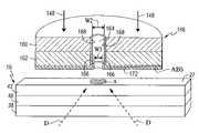
- FIG. 3is a partial schematic side view of a heat assisted magnetic recording head and a magnetic recording medium in accordance with the invention.
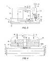
- FIG. 4is a partial sectional view of a multilayer EM radiation emission structure constructed in accordance with the invention.
- FIG. 5is an additional embodiment of a multilayer EM radiation emission structure constructed in accordance with the invention.
- the inventionprovides a heat assisted magnetic recording head, and more particularly a multilayer electromagnetic (EM) radiation emission structure for heat assisted magnetic recording.
- the inventionis particularly suitable for use with a magnetic disc drive storage system although it will be appreciated that the invention may also be used with other type storage systems, such as, for example, magneto-optical or optical storage systems.
- a recording headis generally defined as a head capable of performing read and/or write operations.
- Perpendicular magnetic recordingas used herein, generally refers to orienting magnetic domains within a magnetic storage medium substantially perpendicular to the direction of travel of the recording head and/or recording medium.
- FIG. 2is a pictorial representation of a disc drive 10 that can utilize a heat assisted magnetic recording head, which may be a perpendicular magnetic recording head, constructed in accordance with this invention.
- the disc drive 10includes a housing 12 (with the upper portion removed and the lower portion visible in this view) sized and configured to contain the various components of the disc drive.
- the disc drive 10includes a spindle motor 14 for rotating at least one magnetic storage medium 16 , which may be a perpendicular magnetic recording medium, within the housing.
- At least one arm 18is contained within the housing 12 , with each arm 18 having a first end 20 with a recording head or slider 22 , and a second end 24 pivotally mounted on a shaft by a bearing 26 .
- An actuator motor 28is located at the arm's second end 24 for pivoting the arm 18 to position the recording head 22 over a desired sector or track 27 of the disc 16 .
- the actuator motor 28is regulated by a controller, which is not shown in this view and is well known in the art.
- FIG. 3is a partially schematic side view of a heat assisted magnetic recording head 22 and a magnetic recording medium 16 .
- the recording head 22may include a writer section comprising a main write pole 30 and a return or opposing pole 32 that are magnetically coupled by a yoke or pedestal 35 . It will be appreciated that the recording head 22 may be constructed with a write pole 30 only and no return pole 32 or yoke 35 .
- a magnetization coil 33surrounds the yoke or pedestal 35 for energizing the recording head 22 .
- the recording head 22also may include a read head, not shown, which may be any conventional type read head as is generally known in the art.
- the recording medium 16is positioned adjacent to or under the recording head 22 .
- the recording medium 16includes a substrate 38 , which may be made of any suitable material such as ceramic glass or amorphous glass.
- a soft magnetic underlayer 40is deposited on the substrate 38 .
- the soft magnetic underlayer 40may be made of any suitable material such as, for example, alloys or multilayers having Co, Fe, Ni, Pd, Pt or Ru.
- a hard magnetic recording layer 42is deposited on the soft underlayer 40 , with the perpendicular oriented magnetic domains 44 contained in the hard layer 42 .
- Suitable hard magnetic materials for the hard magnetic recording layer 42may include at least one material selected from, for example, FePt or CoCrPt alloys having a relatively high anisotropy at ambient temperature.
- the recording head 22also includes means for providing a light source and a multilayer EM radiation emission structure 46 to heat the magnetic recording medium 16 proximate to where the write pole 30 applies the magnetic write field H to the recording medium 16 .
- the means for providing a light sourcemay include, for example, an optical waveguide schematically represented by reference number 50 .
- the optical waveguide 50acts in association with a light source 52 which transmits light via an optical fiber 54 that is in optical communication with the optical waveguide 50 .
- the light source 52may be, for example, a laser diode, or other suitable laser light sources.
- EM radiationis transmitted from the EM radiation emission structure 46 for heating the recording medium 16 , and particularly for heating a localized area “A” of the recording layer 42 .
- the optical waveguide 50may include a light transmissive material in optical communication with the light source 52 and optical fiber 54 , as is generally known.
- the light transmissive materialprovides for the described generation of a guided mode which propagates toward the EM radiation emission structure 46 .
- the light transmissive materialmay be formed, for example, from a material, such as SiO 2 , SiN or TiO 2 , as is generally known.
- the means for providing a light sourcemay include other structures or devices such as, for example, a solid immersion lens.
- the multilayer EM radiation emission structure 46is illustrated, for example, in the form of a generally circular optical antenna.
- the multilayer EM radiation emission structure of the present inventionmay be constructed in various shapes and configurations, such as, for example, a bow tie optical antenna or a C-shaped optical antenna structure.
- the EM radiation emission structure 46includes a conducting layer 60 and a protective layer 62 .
- the conducting layer 60is positioned for optical communication with the light energy 48 that propagates from the optical waveguide 50 , as described herein.
- the protective layer 62is formed adjacent the conducting layer 60 and positioned between the conducting layer 60 and the recording medium 16 so as to protect the conducting layer 60 from contact with the recording medium 16 .
- the conducting layer 60may comprise at least one material selected from the group consisting of Au, Ag, or Al.
- the conducting layer 60may have a thickness 60 t in the range of about 10 nm to about 1000 nm.
- the protective layer 62may comprise at least one material selected from the group consisting of Ta, Ti, W, Mo or Cr.
- the protective layer 62may have a thickness 62 t in the range of about 0.5 nm to about 100 nm.
- the EM radiation emission structure 46defines an aperture 64 that extends therethrough, and particularly extends through the conducting layer 60 and the protective layer 62 .
- the propagating light 48impinges upon the conducting layer 60 of the EM radiation emission structure 46 .
- the aperture 64may serve as a filter to filter out all of the light outside of the aperture width W 1 , or surface plasmons may be generated by the light 48 impinging upon the conducting layer 60 . If plasmons are generated, they may propagate along the surface of the layer 60 to the aperture 64 and enhance the amount of light passing therethrough.
- the aperture 64has a width W 1 in the range of about 1 nm to about 250 nm.
- the formation of the EM radiation emission structure 46 having the protective layer 62 between the conducting layer 60 and the recording medium 16is beneficial because, as stated, the conducting layer 60 is formed of a mechanically soft conducting material that is not well suited to withstand any possible start/stop and intermittent contact that may occur with the recording medium, as is typically existent in low flying magnetic disc recording systems.
- the protective layer 62better serves to protect the conducting layer 60 than other known techniques that are employed for protecting recording heads, and particularly the ABS thereof, from contact with the recording medium 16 .
- Such known techniquesinclude, for example, providing an overcoat material, such as a diamond-like carbon overcoat (DLC) on the ABS of a slider or a recording head 22 .
- DLCdiamond-like carbon overcoat
- An advantage of having the protective layer 62 as opposed to merely relying on the DLC overcoatis that the mechanically hard protective layer 62 adheres better to the conducting layer 60 as compared to the adhesion of the DLC overcoat to the conducting layer 60 .
- the material for forming the protective layer 62may be chosen such that the DLC overcoat adheres well thereto and the DLC overcoat more easily forms a thin uniform coating.
- the EM radiation emission structure 46may also include, if desired, a DLC overcoat applied to the ABS thereof, i.e., a DLC overcoat applied to the ABS of the protective layer 62 .
- the thin film growth modeis mainly governed by surface and interface free energies.
- the conducting layer 60is formed of Au (which has a relatively low surface free energy) and if it does not form a suitably strong bond with the C of the DLC overcoat, a thin continuous layer of DLC will not be possible.
- the protective layer 62is formed of Ta which may form bonds with Au, it may effectively coat the Au and then a thin DLC coating could be applied to the Ta protective layer 62 .
- the protective layer 62actually defines a portion of the aperture 64 . This means that the protective layer 62 can be made much thicker than the layer of DLC overcoat and, therefore, more reliable than the DLC overcoat.
- the protective layer 62can reduce the edge coupling of the plasmons to the medium 16 and since the plasmons would not propagate along the hard protective layer 62 , the thermal profile would be much sharper with reduced side heating.
- the EM radiation emission structure 146may include a conducting layer 160 and a protective layer 162 .
- the conducting layer 160 and the protective layer 162define an aperture 164 that extends therethrough.
- the EM radiation emission structure 146may include an additional conducting layer 166 that may be formed on at least a portion of a sidewall 168 of the aperture 164 and/or on at least a portion of the ABS of the EM radiation emission structure 146 .
- the additional conducting layer 166may comprise at least one material selected from the group consisting of Au, Ag, or Al.
- An advantage of having an additional conducting layer 166 , and particularly of having an additional conducting layer 166 formed on at least a portion of the sidewall 168 of the aperture 164 ,is that the width of the aperture 164 may be reduced to a width of W 2 to allow for the generation of an even smaller, intense hot spot “A” on the recording medium 16 .
- W 2may be in the range of about 1 nm to about 50 nm.
- the EM radiation emission structure 146may also include an additional protective layer 172 that may be formed on at least a portion of the additional conducting layer 166 .
- the protective layer 162may or may not be used in conjunction with the additional protective layer 172 .
- the additional protective layer 172may comprise at least one material selected from the group consisting of Ta, Ti, W, Mo or Cr.
- An advantage of providing the additional protective layer 172is that the width of the aperture 164 may be further reduced to the width W 3 to produce an even smaller, intense hot spot for heating the recording medium 16 .
- W 3may be in the range of about 1 nm to about 50 nm.
- the additional protective layermay be formed directly on at least a portion of the sidewall 168 of the aperture 164 or on the ABS of the heat emission structure 146 .
- the layer 162In the situation where surface plasmons are being generated, the layer 162 would need to be made of a material, such as Au, Ag, or Al, that would support propagation of these plasmons.
- the protective layer 172may or may not be used to further reduce the width of the aperture 164 .
- the protective layer 172would need to be constructed of a material, such as Ta, Ti, W, Mo, or Cr, that would stop the propagation of the plasmons and allow for the energy to be transmitted to the recording medium 16 to heat the localized area A thereof.
- the layer 162could be formed of any non-transparent material, such as Ta, Ti, W, Mo, Cr, Zr, Nb, Al, or Ag.
- the protective layer 172would then be needed to protect the layer 162 in the event that it was formed of a relatively soft material.
- the means for providing a light source and the EM radiation emission structures 46 and 146may be located adjacent to the write pole 30 .
- thiswould allow for heating of the recording medium 16 in close proximity to where the write pole 30 applies the magnetic write field H to the recording medium 16 .
- Italso provides for the ability to align the EM radiation emission structures 46 and 146 with the write pole 30 to maintain the heating application in the same track 27 of the medium 16 where the writing is taking place. Locating the EM radiation emission structures 46 and 146 adjacent to the write pole 30 provides for increased writing efficiency due to the write field H being applied immediately downtrack from where the recording medium 16 has been heated.
- the structures 46 and/or 146may be positioned in different locations relative to the write pole 30 for heating the medium 16 either before, after or at about the same time as the write field H is applied.
- the recording medium 16is passed under the recording head 22 .
- the recording medium 16may travel in either direction under the recording head 22 since the write pole 30 and the EM radiation emission structure 46 are located in close proximity.
- the light source 52transmits light energy via the optical fiber 54 to the optical waveguide 50 .
- the optical waveguide 50transmits the light energy to the EM radiation emission structure 46 or 146 for heating the recording medium 16 .
- a localized area A of the recording layer 42is heated to lower the coercivity thereof prior to the write pole 30 applying a magnetic write field H to the recording medium 16 .
- thisallows for a higher coercivity medium material to be used which limits the superparamagnetic instabilities that may occur with such recording media used for high recording densities.
- the magnetic write pole 30applies a magnetic write field to the medium 16 for storing magnetic data in the recording medium 16 .
- the write field His applied while the recording medium 16 remains at a sufficiently high temperature for lowering the coercivity of the recording medium 16 . This insures that the write pole 30 can provide a sufficient or strong enough magnetic write field to perform a write operation on the recording medium 16 .
- the inventionalso includes a method for making the multilayer EM radiation emission structures 46 and 146 .
- the methodincludes depositing the conducting layer 60 for optically communicating with the means for providing a light source as described herein.
- the methodalso includes depositing the protective layer 62 adjacent the conducting layer 60 such that the protective layer 62 is positioned for protecting the conducting layer 60 from contact that may occur with the recording medium 16 .
- the protective layer 62may be deposited so as to be in direct contact with the conducting layer 60 or an interlayer could be used therebetween to promote adhesion between the conducting layer 60 and the protective layer 62 .
- the depositing of the conducting layer 60 and the protective layer 62may be carried out using conventional deposition techniques such as, for example, sputtering or ion beam deposition.
- the methodalso includes forming the aperture 64 that extends through the conducting layer 60 and the protective layer 62 to allow the light energy to pass therethrough to heat the recording medium 16 .
- Formation of the aperture 64may include some additional post-deposition processing. For example, known techniques of an etching process or a lift-off process could be utilized in forming the aperture 64 .
- the method of making the EM radiation emission structure 146may include additional steps to deposit the additional conducting layer 166 and/or the additional protective layer 172 .
- the deposition of the additional conducting layer 166 and/or the additional protective layer 172may be carried out using a directional deposition technique such as, for example, ion beam deposition, evaporation, or collimated sputtering which would provide for sufficient film growth rate on the sidewall 168 of the aperture 164 .
- the directional deposition of the additional conducting layer 166 and/or the additional protective layer 172is applied, as indicated by arrows D at an angle with respect to the plane of the conducting layer 160 and the protective layer 162 .
- the angle of the deposition D and the angle at which the incoming material would make contact with the surfacecan be used to control how deep the conductive layer 166 and/or the protective layer 172 extends into the aperture 164 . This further enhances the ability to form the additional conducting layer 166 and/or the additional protective layer 172 on the sidewall 168 .
Landscapes
- Engineering & Computer Science (AREA)
- Chemical & Material Sciences (AREA)
- Nanotechnology (AREA)
- Manufacturing & Machinery (AREA)
- Physics & Mathematics (AREA)
- Mathematical Physics (AREA)
- Theoretical Computer Science (AREA)
- Crystallography & Structural Chemistry (AREA)
- Recording Or Reproducing By Magnetic Means (AREA)
- Magnetic Heads (AREA)
Abstract
Description
Claims (26)
Priority Applications (1)
| Application Number | Priority Date | Filing Date | Title |
|---|---|---|---|
| US11/286,720US7518815B2 (en) | 2002-04-18 | 2005-11-23 | Heat assisted magnetic recording head with multilayer electromagnetic radiation emission structure |
Applications Claiming Priority (3)
| Application Number | Priority Date | Filing Date | Title |
|---|---|---|---|
| US37350002P | 2002-04-18 | 2002-04-18 | |
| US10/226,805US20030198146A1 (en) | 2002-04-18 | 2002-08-23 | Heat assisted magnetic recording head with multilayer electromagnetic radiation emission structure |
| US11/286,720US7518815B2 (en) | 2002-04-18 | 2005-11-23 | Heat assisted magnetic recording head with multilayer electromagnetic radiation emission structure |
Related Parent Applications (1)
| Application Number | Title | Priority Date | Filing Date |
|---|---|---|---|
| US10/226,805ContinuationUS20030198146A1 (en) | 2002-04-18 | 2002-08-23 | Heat assisted magnetic recording head with multilayer electromagnetic radiation emission structure |
Publications (2)
| Publication Number | Publication Date |
|---|---|
| US20060083116A1 US20060083116A1 (en) | 2006-04-20 |
| US7518815B2true US7518815B2 (en) | 2009-04-14 |
Family
ID=29218448
Family Applications (2)
| Application Number | Title | Priority Date | Filing Date |
|---|---|---|---|
| US10/226,805AbandonedUS20030198146A1 (en) | 2002-04-18 | 2002-08-23 | Heat assisted magnetic recording head with multilayer electromagnetic radiation emission structure |
| US11/286,720Expired - LifetimeUS7518815B2 (en) | 2002-04-18 | 2005-11-23 | Heat assisted magnetic recording head with multilayer electromagnetic radiation emission structure |
Family Applications Before (1)
| Application Number | Title | Priority Date | Filing Date |
|---|---|---|---|
| US10/226,805AbandonedUS20030198146A1 (en) | 2002-04-18 | 2002-08-23 | Heat assisted magnetic recording head with multilayer electromagnetic radiation emission structure |
Country Status (1)
| Country | Link |
|---|---|
| US (2) | US20030198146A1 (en) |
Cited By (15)
| Publication number | Priority date | Publication date | Assignee | Title |
|---|---|---|---|---|
| US20070036040A1 (en)* | 2005-08-11 | 2007-02-15 | Seagate Technology Llc | Dual wire integrated WAMR/HAMR writing head |
| US20080055762A1 (en)* | 2006-08-31 | 2008-03-06 | Tdk Corporation | Thermally assisted magnetic head, head gimbal assembly, and hard disk drive |
| US20090207703A1 (en)* | 2002-11-01 | 2009-08-20 | Hitachi, Ltd. | Optical near-field generator and recording apparatus using the optical near-field generator |
| US20100073802A1 (en)* | 2008-09-25 | 2010-03-25 | Tdk Corporation | Thermally assisted magnetic head having an asymmetric plasmon antenna and manufacturing method thereof |
| US20100097901A1 (en)* | 2008-10-16 | 2010-04-22 | Seagate Technology Llc | Polarization conserving near field transducer for optical recording on magnetic media |
| US20100103553A1 (en)* | 2008-10-29 | 2010-04-29 | Tdk Corporation | Surface plasmon antenna with propagation edge and near-field light generating element |
| US8351151B2 (en) | 2010-11-02 | 2013-01-08 | Hitachi Global Storage Technologies Netherlands B.V. | Thermally assisted magnetic write head employing a near field transducer (NFT) having a diffusion barrier layer between the near field transducer and a magnetic lip |
| US20140334277A1 (en)* | 2013-05-08 | 2014-11-13 | Seagate Technology Llc | Light delivery apparatus |
| US8902720B1 (en) | 2014-04-17 | 2014-12-02 | HGST Netherlands B.V. | Heat-assisted magnetic recording (HAMR) write head with protective film for near-field transducer |
| US9036307B1 (en) | 2014-10-09 | 2015-05-19 | HGST Netherlands B.V. | Heat-assisted magnetic recording (HAMR) write head with recessed near-field transducer and optically transparent protective film |
| US20150269959A1 (en)* | 2014-03-24 | 2015-09-24 | Purdue Research Foundation | Near field transducer for heat assisted magnetic recording |
| US9852749B2 (en)* | 2015-06-16 | 2017-12-26 | Western Digital Technologies, Inc. | Near field transducer having an adhesion layer coupled thereto |
| WO2019050644A1 (en)* | 2017-09-05 | 2019-03-14 | Waymo Llc | Lidar with co-aligned transmit and receive paths |
| US10614850B1 (en)* | 2019-03-12 | 2020-04-07 | Seagate Technology Llc | Coating a near field transducer with a dielectric material from magnetic recording medium |
| US11041753B2 (en) | 2016-12-03 | 2021-06-22 | Waymo Llc | Light detection using an aperture |
Families Citing this family (36)
| Publication number | Priority date | Publication date | Assignee | Title |
|---|---|---|---|---|
| US7480214B2 (en)* | 2003-12-08 | 2009-01-20 | Seagate Technology Llc | Efficient waveguide coupler for data recording transducer |
| US7345840B2 (en)* | 2004-05-26 | 2008-03-18 | Seagate Technology Llc | Light delivery technique for heat assisted magnetic recording head |
| US7500255B2 (en)* | 2004-06-29 | 2009-03-03 | Seagate Technology Llc | Data writing with plasmon resonator |
| US7489597B2 (en)* | 2004-09-27 | 2009-02-10 | Sharp Kabushiki Kaisha | Electromagnetic field generating element, information recording/reproducing head, and information recording/reproducing apparatus |
| US7483229B2 (en)* | 2004-12-08 | 2009-01-27 | Seagate Technology Llc | Optical coupling to data recording transducer |
| US7251089B2 (en)* | 2005-01-07 | 2007-07-31 | Seagate Technology Llc | Storage medium with overcoat layer for enhanced heating |
| US20070058686A1 (en)* | 2005-08-16 | 2007-03-15 | Federico Capasso | Active optical antenna |
| KR100657971B1 (en)* | 2005-10-06 | 2006-12-14 | 삼성전자주식회사 | Optical Transmission Module and Thermal Auxiliary Magnetic Recording Head |
| KR100707209B1 (en)* | 2006-01-11 | 2007-04-13 | 삼성전자주식회사 | Thermal auxiliary magnetic recording head and its manufacturing method |
| US7649677B2 (en)* | 2006-04-04 | 2010-01-19 | Hitachi Global Storage Technologies Netherlands B.V. | Multi-ridged subwavelength aperture for optical transmission and thermally assisted magnetic recording |
| US7729085B2 (en)* | 2006-04-04 | 2010-06-01 | Hitachi Global Storage Technologies Netherlands B.V. | Thermally assisted recording of magnetic media using an optical resonant cavity |
| JP2008059645A (en)* | 2006-08-30 | 2008-03-13 | Hitachi Ltd | Recording head |
| US8223330B2 (en) | 2007-02-13 | 2012-07-17 | William Marsh Rice University | Nanostructures and lithographic method for producing highly sensitive substrates for surface-enhanced spectroscopy |
| JP4364912B2 (en)* | 2007-02-26 | 2009-11-18 | Tdk株式会社 | Thermally assisted magnetic head, head gimbal assembly, and hard disk drive |
| JP2009076166A (en)* | 2007-09-21 | 2009-04-09 | Sony Corp | Light-assisted magnetic head, light-assisted magnetic recording device and method |
| US8259539B1 (en) | 2008-12-17 | 2012-09-04 | Western Digital (Fremont), Llc | Integration of a vertical cavity surface emitting laser (VCSEL) on an energy-assisted magnetic recording (EAMR) head |
| US8164855B1 (en) | 2009-11-06 | 2012-04-24 | Western Digital (Fremont), Llc | Method and system for providing a write pole in an energy assisted magnetic recording disk drive |
| US8625941B1 (en) | 2010-05-20 | 2014-01-07 | Western Digital (Fremont), Llc | Broadband reflective waveguide metal gratings and their formation |
| US8310901B1 (en) | 2010-06-09 | 2012-11-13 | Western Digital (Fremont), Llc | Method and system for providing separate write and optical modules in an energy assisted magnetic recording disk drive |
| US8456964B1 (en) | 2010-11-16 | 2013-06-04 | Western Digital (Fremont), Llc | Energy assisted magnetic recording head having a reflector for improving efficiency of the light beam |
| US8325569B1 (en) | 2011-06-27 | 2012-12-04 | Western Digital (Fremont), Llc | EAMR head having improved optical coupling efficiency |
| US8787126B2 (en)* | 2011-10-10 | 2014-07-22 | Seagate Technology Llc | Waveguide with blocking layer |
| US8675455B1 (en) | 2012-02-17 | 2014-03-18 | Western Digital (Fremont), Llc | Systems and methods for controlling light phase difference in interferometric waveguides at near field transducers |
| US8670294B1 (en) | 2012-02-17 | 2014-03-11 | Western Digital (Fremont), Llc | Systems and methods for increasing media absorption efficiency using interferometric waveguides |
| US9792935B2 (en)* | 2012-12-21 | 2017-10-17 | Seagate Technology Llc | Magnetic devices with variable overcoats |
| US9286920B1 (en) | 2013-01-31 | 2016-03-15 | Western Digital (Fremont), Llc | Method for compensating for phase variations in an interferometric tapered waveguide in a heat assisted magnetic recording head |
| US9336814B1 (en) | 2013-03-12 | 2016-05-10 | Western Digital (Fremont), Llc | Inverse tapered waveguide for use in a heat assisted magnetic recording head |
| US9064527B1 (en) | 2013-04-12 | 2015-06-23 | Western Digital (Fremont), Llc | High order tapered waveguide for use in a heat assisted magnetic recording head |
| US9064528B1 (en) | 2013-05-17 | 2015-06-23 | Western Digital Technologies, Inc. | Interferometric waveguide usable in shingled heat assisted magnetic recording in the absence of a near-field transducer |
| US8830800B1 (en)* | 2013-06-21 | 2014-09-09 | Seagate Technology Llc | Magnetic devices including film structures |
| US8947985B1 (en) | 2013-07-16 | 2015-02-03 | Western Digital (Fremont), Llc | Heat assisted magnetic recording transducers having a recessed pole |
| US8923102B1 (en) | 2013-07-16 | 2014-12-30 | Western Digital (Fremont), Llc | Optical grating coupling for interferometric waveguides in heat assisted magnetic recording heads |
| US9142233B1 (en) | 2014-02-28 | 2015-09-22 | Western Digital (Fremont), Llc | Heat assisted magnetic recording writer having a recessed pole |
| US9190085B1 (en) | 2014-03-12 | 2015-11-17 | Western Digital (Fremont), Llc | Waveguide with reflective grating for localized energy intensity |
| US10049689B2 (en) | 2015-08-27 | 2018-08-14 | Seagate Technology Llc | Methods of forming magnetic devices with variable overcoats |
| US20170372734A1 (en)* | 2016-06-24 | 2017-12-28 | Symphonious Technologies, LLC | Magnetic recording head utilizing focused optical-thermal energy and a system and method of use |
Citations (24)
| Publication number | Priority date | Publication date | Assignee | Title |
|---|---|---|---|---|
| US5224068A (en) | 1990-01-10 | 1993-06-29 | Sharp Kabushiki Kaisha | Recording method for magneto-optic memory medium |
| US5674638A (en) | 1994-11-02 | 1997-10-07 | International Business Machines Corporation | Fluorinated diamond-like carbon protective coating for magnetic recording media devices |
| US5696372A (en) | 1996-07-31 | 1997-12-09 | Yale University | High efficiency near-field electromagnetic probe having a bowtie antenna structure |
| US5771216A (en) | 1990-01-31 | 1998-06-23 | Sony Corporation | Photomagnetic recording device and photomagnetic reproducing device |
| US5995474A (en) | 1993-02-17 | 1999-11-30 | Hitachi, Ltd. | Flying type optical head integrally formed with light source and photodetector and optical disk apparatus with the same |
| US6130864A (en) | 1999-03-04 | 2000-10-10 | Terastor Corporation | Method and apparatus for generating magnetic field for magneto-optic recording system |
| US6132875A (en) | 1993-09-12 | 2000-10-17 | Fujitsu Limited | Magnetic recording medium and magnetic head having carbon protective layers |
| US6192008B1 (en) | 1997-10-31 | 2001-02-20 | Lg Electronics, Inc. | Device and method for reproducing record information from magneto-optical recording medium |
| US6320841B1 (en) | 1998-10-07 | 2001-11-20 | Sony Corporation | Slider for optical head |
| US6388954B1 (en) | 1998-03-31 | 2002-05-14 | Hitachi Maxell, Ltd. | Magneto-optical recording medium having clock-marks on recording layer and apparatus for recording and reproducing same |
| US6396773B1 (en) | 1997-12-12 | 2002-05-28 | Seagate Technology Llc | Photo servo patterning on magneto-optical media |
| US6498776B1 (en) | 1999-02-01 | 2002-12-24 | Minolta Co., Ltd. | Near field light emitting element and optical head |
| US20030123334A1 (en) | 2001-12-27 | 2003-07-03 | Fujitsu Limited | Optical head and optical information processing apparatus |
| US6618330B1 (en) | 2000-09-07 | 2003-09-09 | Fujitsu Limited | Magneto-optical head and method of making coil for the same |
| US6633513B1 (en) | 1999-06-24 | 2003-10-14 | Samsung Electronics Co., Ltd. | Magneto-optical head for magneto-optical reading and writing system |
| US6704249B2 (en) | 2001-08-03 | 2004-03-09 | Fujitsu Limited | Magnetic head having an irregular surface for heat dissipation |
| US6714370B2 (en) | 2002-01-07 | 2004-03-30 | Seagate Technology Llc | Write head and method for recording information on a data storage medium |
| US6760278B2 (en) | 2001-12-11 | 2004-07-06 | Fujitsu Limited | Magnetic head and data recording and reproduction device |
| US6771589B2 (en)* | 2000-05-10 | 2004-08-03 | Fuji Xerox Co., Ltd. | Flying recording head having semiconductor laser formed by growing semiconductor crystal, and method of manufacturing same |
| US6781926B2 (en) | 2000-10-10 | 2004-08-24 | Hitachi Maxell, Limited | Magneto-optical head having heat sink layer |
| US6795380B2 (en) | 2001-03-29 | 2004-09-21 | Kabushiki Kaisha Toshiba | Optically-assisted magnetic recording head and optically-assisted magnetic recording apparatus |
| US6844983B2 (en) | 2002-12-31 | 2005-01-18 | Industrial Technology Research Institute | Near-field objective lens for an optical head |
| US20070081426A1 (en)* | 2005-10-12 | 2007-04-12 | Samsung Electronics Co., Ltd. | Near field light generating device and heat assisted magnetic recording head with the same |
| US20070081427A1 (en)* | 2005-10-06 | 2007-04-12 | Samsung Electronics Co., Ltd. | Light delivery module and heat-assisted magnet recording head employing the same |
Family Cites Families (1)
| Publication number | Priority date | Publication date | Assignee | Title |
|---|---|---|---|---|
| GB2380807B (en)* | 2000-08-04 | 2004-07-07 | Jr Joseph David Evankow | Apparatus for polarization-independent optical polarization scrambler and a method for use therein |
- 2002
- 2002-08-23USUS10/226,805patent/US20030198146A1/ennot_activeAbandoned
- 2005
- 2005-11-23USUS11/286,720patent/US7518815B2/ennot_activeExpired - Lifetime
Patent Citations (24)
| Publication number | Priority date | Publication date | Assignee | Title |
|---|---|---|---|---|
| US5224068A (en) | 1990-01-10 | 1993-06-29 | Sharp Kabushiki Kaisha | Recording method for magneto-optic memory medium |
| US5771216A (en) | 1990-01-31 | 1998-06-23 | Sony Corporation | Photomagnetic recording device and photomagnetic reproducing device |
| US5995474A (en) | 1993-02-17 | 1999-11-30 | Hitachi, Ltd. | Flying type optical head integrally formed with light source and photodetector and optical disk apparatus with the same |
| US6132875A (en) | 1993-09-12 | 2000-10-17 | Fujitsu Limited | Magnetic recording medium and magnetic head having carbon protective layers |
| US5674638A (en) | 1994-11-02 | 1997-10-07 | International Business Machines Corporation | Fluorinated diamond-like carbon protective coating for magnetic recording media devices |
| US5696372A (en) | 1996-07-31 | 1997-12-09 | Yale University | High efficiency near-field electromagnetic probe having a bowtie antenna structure |
| US6192008B1 (en) | 1997-10-31 | 2001-02-20 | Lg Electronics, Inc. | Device and method for reproducing record information from magneto-optical recording medium |
| US6396773B1 (en) | 1997-12-12 | 2002-05-28 | Seagate Technology Llc | Photo servo patterning on magneto-optical media |
| US6388954B1 (en) | 1998-03-31 | 2002-05-14 | Hitachi Maxell, Ltd. | Magneto-optical recording medium having clock-marks on recording layer and apparatus for recording and reproducing same |
| US6320841B1 (en) | 1998-10-07 | 2001-11-20 | Sony Corporation | Slider for optical head |
| US6498776B1 (en) | 1999-02-01 | 2002-12-24 | Minolta Co., Ltd. | Near field light emitting element and optical head |
| US6130864A (en) | 1999-03-04 | 2000-10-10 | Terastor Corporation | Method and apparatus for generating magnetic field for magneto-optic recording system |
| US6633513B1 (en) | 1999-06-24 | 2003-10-14 | Samsung Electronics Co., Ltd. | Magneto-optical head for magneto-optical reading and writing system |
| US6771589B2 (en)* | 2000-05-10 | 2004-08-03 | Fuji Xerox Co., Ltd. | Flying recording head having semiconductor laser formed by growing semiconductor crystal, and method of manufacturing same |
| US6618330B1 (en) | 2000-09-07 | 2003-09-09 | Fujitsu Limited | Magneto-optical head and method of making coil for the same |
| US6781926B2 (en) | 2000-10-10 | 2004-08-24 | Hitachi Maxell, Limited | Magneto-optical head having heat sink layer |
| US6795380B2 (en) | 2001-03-29 | 2004-09-21 | Kabushiki Kaisha Toshiba | Optically-assisted magnetic recording head and optically-assisted magnetic recording apparatus |
| US6704249B2 (en) | 2001-08-03 | 2004-03-09 | Fujitsu Limited | Magnetic head having an irregular surface for heat dissipation |
| US6760278B2 (en) | 2001-12-11 | 2004-07-06 | Fujitsu Limited | Magnetic head and data recording and reproduction device |
| US20030123334A1 (en) | 2001-12-27 | 2003-07-03 | Fujitsu Limited | Optical head and optical information processing apparatus |
| US6714370B2 (en) | 2002-01-07 | 2004-03-30 | Seagate Technology Llc | Write head and method for recording information on a data storage medium |
| US6844983B2 (en) | 2002-12-31 | 2005-01-18 | Industrial Technology Research Institute | Near-field objective lens for an optical head |
| US20070081427A1 (en)* | 2005-10-06 | 2007-04-12 | Samsung Electronics Co., Ltd. | Light delivery module and heat-assisted magnet recording head employing the same |
| US20070081426A1 (en)* | 2005-10-12 | 2007-04-12 | Samsung Electronics Co., Ltd. | Near field light generating device and heat assisted magnetic recording head with the same |
Non-Patent Citations (4)
| Title |
|---|
| R. D. Grober et al., "Optical Antenna: Towards A Unity Efficiency Near-Field Optical Probe", Appl. Phys. Lett., vol. 70, No. 11, Mar. 1997, pp. 1354-1356. |
| T. E. Schlesinger et al., "An Integrated Read/Write Head For Hybrid Recording", Jpn. J. Appl. Phys., vol. 41, Pt. 1, No. 3B, (2002), pp. 1821-1824. |
| X. Shi et al., "A Nano-Aperture With 1000X Power Throughput Enhancement For Very Small Aperture Laser System (VSAL)", Proceedings of SPIE, vol. 4342 (2002), pp. 320-327. |
| Y. Leviatan, "Study Of Near-Zone Fields Of A Small Aperture", J. Appl. Phys., vol. 60, No. 5, Sep. 1986, pp. 1577-1583. |
Cited By (26)
| Publication number | Priority date | Publication date | Assignee | Title |
|---|---|---|---|---|
| US20090207703A1 (en)* | 2002-11-01 | 2009-08-20 | Hitachi, Ltd. | Optical near-field generator and recording apparatus using the optical near-field generator |
| US7933169B2 (en)* | 2002-11-01 | 2011-04-26 | Hitachi, Ltd. | Optical head for near-field recording and reproducing device |
| US20070036040A1 (en)* | 2005-08-11 | 2007-02-15 | Seagate Technology Llc | Dual wire integrated WAMR/HAMR writing head |
| US7869309B2 (en)* | 2005-08-11 | 2011-01-11 | Seagate Technology Llc | Dual wire integrated WAMR/HAMR writing head |
| US20080055762A1 (en)* | 2006-08-31 | 2008-03-06 | Tdk Corporation | Thermally assisted magnetic head, head gimbal assembly, and hard disk drive |
| US7940486B2 (en)* | 2006-08-31 | 2011-05-10 | Tdk Corporation | Thermally assisted magnetic head, head gimbal assembly, and hard disk drive |
| US20100073802A1 (en)* | 2008-09-25 | 2010-03-25 | Tdk Corporation | Thermally assisted magnetic head having an asymmetric plasmon antenna and manufacturing method thereof |
| US7821732B2 (en)* | 2008-09-25 | 2010-10-26 | Tdk Corporation | Thermally assisted magnetic head having an asymmetric plasmon antenna and manufacturing method thereof |
| US20100097901A1 (en)* | 2008-10-16 | 2010-04-22 | Seagate Technology Llc | Polarization conserving near field transducer for optical recording on magnetic media |
| US8040760B2 (en)* | 2008-10-16 | 2011-10-18 | Seagate Technology Llc | Polarization near-field transducer having optical conductive blades |
| US20100103553A1 (en)* | 2008-10-29 | 2010-04-29 | Tdk Corporation | Surface plasmon antenna with propagation edge and near-field light generating element |
| US8000178B2 (en)* | 2008-10-29 | 2011-08-16 | Tdk Corporation | Near-field light generating element utilizing surface plasmon |
| US8351151B2 (en) | 2010-11-02 | 2013-01-08 | Hitachi Global Storage Technologies Netherlands B.V. | Thermally assisted magnetic write head employing a near field transducer (NFT) having a diffusion barrier layer between the near field transducer and a magnetic lip |
| US20140334277A1 (en)* | 2013-05-08 | 2014-11-13 | Seagate Technology Llc | Light delivery apparatus |
| US8971159B2 (en)* | 2013-05-08 | 2015-03-03 | Seagate Technology Llc | Light delivery apparatus |
| US20150269959A1 (en)* | 2014-03-24 | 2015-09-24 | Purdue Research Foundation | Near field transducer for heat assisted magnetic recording |
| US9437228B2 (en)* | 2014-03-24 | 2016-09-06 | Purdue Research Foundation | Near field transducer for heat assisted magnetic recording |
| US8902720B1 (en) | 2014-04-17 | 2014-12-02 | HGST Netherlands B.V. | Heat-assisted magnetic recording (HAMR) write head with protective film for near-field transducer |
| US9036307B1 (en) | 2014-10-09 | 2015-05-19 | HGST Netherlands B.V. | Heat-assisted magnetic recording (HAMR) write head with recessed near-field transducer and optically transparent protective film |
| US9852749B2 (en)* | 2015-06-16 | 2017-12-26 | Western Digital Technologies, Inc. | Near field transducer having an adhesion layer coupled thereto |
| US11041753B2 (en) | 2016-12-03 | 2021-06-22 | Waymo Llc | Light detection using an aperture |
| US12078530B2 (en) | 2016-12-03 | 2024-09-03 | Waymo Llc | Light detection using an aperture |
| WO2019050644A1 (en)* | 2017-09-05 | 2019-03-14 | Waymo Llc | Lidar with co-aligned transmit and receive paths |
| US10890650B2 (en) | 2017-09-05 | 2021-01-12 | Waymo Llc | LIDAR with co-aligned transmit and receive paths |
| US11802942B2 (en) | 2017-09-05 | 2023-10-31 | Waymo Llc | LIDAR with co-aligned transmit and receive paths |
| US10614850B1 (en)* | 2019-03-12 | 2020-04-07 | Seagate Technology Llc | Coating a near field transducer with a dielectric material from magnetic recording medium |
Also Published As
| Publication number | Publication date |
|---|---|
| US20030198146A1 (en) | 2003-10-23 |
| US20060083116A1 (en) | 2006-04-20 |
Similar Documents
| Publication | Publication Date | Title |
|---|---|---|
| US7518815B2 (en) | Heat assisted magnetic recording head with multilayer electromagnetic radiation emission structure | |
| US9047908B2 (en) | Heat-assisted magnetic recording (HAMR) head with diffusion barrier between waveguide core and write pole lip | |
| US10083713B1 (en) | Heat-assisted magnetic recording (HAMR) write head with protective multilayer film for near-field transducer | |
| US8405932B2 (en) | HAMR recording head having a sloped wall pole | |
| US11651791B2 (en) | Heat-assisted magnetic recording (HAMR) head with tapered main pole and heat sink material adjacent the pole | |
| US8351305B2 (en) | Notched pole design for HAMR recording | |
| US9036307B1 (en) | Heat-assisted magnetic recording (HAMR) write head with recessed near-field transducer and optically transparent protective film | |
| US8509039B1 (en) | Thermally-assisted recording (TAR) disk with low thermal-conductivity underlayer | |
| US7869162B2 (en) | Thin film structure with controlled lateral thermal spreading in the thin film | |
| US8619516B1 (en) | Thermally-assisted recording (TAR) head with conductive layer between the near-field transducer and the write pole | |
| JP6039951B2 (en) | Magnetic recording disk drive using single writing and rectangular optical waveguide for wide area heat assist | |
| US11437064B1 (en) | Heat-assisted magnetic recording (HAMR) medium with optical-coupling multilayer between the recording layer and heat-sink layer | |
| US10276202B1 (en) | Heat-assisted magnetic recording (HAMR) medium with rhodium or rhodium-based alloy heat-sink layer | |
| US11521648B2 (en) | Heat-assisted magnetic recording (HAMR) medium with multilayered underlayer for the recording layer | |
| US8830629B2 (en) | Thin film structure with controlled lateral thermal spreading in the thin film | |
| US10109309B1 (en) | Heat-assisted magnetic recording (HAMR) medium with heat-sink layer having anisotropic thermal conductivity | |
| US10650854B1 (en) | Heat-assisted magnetic recording (HAMR) medium with improved corrosion resistance | |
| US11127421B1 (en) | Heat-assisted magnetic recording (HAMR) write head with improved corrosion resistance and method for making the head | |
| US9824710B1 (en) | Heat-assisted magnetic recording (HAMR) medium with thermal barrier layer in multilayered heat-sink structure | |
| US10522176B1 (en) | Heat-assisted magnetic recording (HAMR) read/write head with reversed read head and write head | |
| US9601145B1 (en) | Heat-assisted magnetic recording (HAMR) disk with multiple continuous magnetic recording layers | |
| JP6050731B2 (en) | Thermally assisted recording (TAR) head with reflective layer for near-field transducer | |
| US11532329B1 (en) | Heat-assisted magnetic recording (HAMR) head with main pole having recess for plasmonic material | |
| CN114944169B (en) | Thermally assisted magnetic recording (HAMR) head with optical reflective shielding material adjacent to waveguide | |
| US20180005658A1 (en) | Anti-reflection data storage medium |
Legal Events
| Date | Code | Title | Description |
|---|---|---|---|
| STCF | Information on status: patent grant | Free format text:PATENTED CASE | |
| AS | Assignment | Owner name:WELLS FARGO BANK, NATIONAL ASSOCIATION, AS COLLATERAL AGENT AND SECOND PRIORITY REPRESENTATIVE, CALIFORNIA Free format text:SECURITY AGREEMENT;ASSIGNORS:MAXTOR CORPORATION;SEAGATE TECHNOLOGY LLC;SEAGATE TECHNOLOGY INTERNATIONAL;REEL/FRAME:022757/0017 Effective date:20090507 Owner name:JPMORGAN CHASE BANK, N.A., AS ADMINISTRATIVE AGENT AND FIRST PRIORITY REPRESENTATIVE, NEW YORK Free format text:SECURITY AGREEMENT;ASSIGNORS:MAXTOR CORPORATION;SEAGATE TECHNOLOGY LLC;SEAGATE TECHNOLOGY INTERNATIONAL;REEL/FRAME:022757/0017 Effective date:20090507 Owner name:JPMORGAN CHASE BANK, N.A., AS ADMINISTRATIVE AGENT Free format text:SECURITY AGREEMENT;ASSIGNORS:MAXTOR CORPORATION;SEAGATE TECHNOLOGY LLC;SEAGATE TECHNOLOGY INTERNATIONAL;REEL/FRAME:022757/0017 Effective date:20090507 Owner name:WELLS FARGO BANK, NATIONAL ASSOCIATION, AS COLLATE Free format text:SECURITY AGREEMENT;ASSIGNORS:MAXTOR CORPORATION;SEAGATE TECHNOLOGY LLC;SEAGATE TECHNOLOGY INTERNATIONAL;REEL/FRAME:022757/0017 Effective date:20090507 | |
| AS | Assignment | Owner name:SEAGATE TECHNOLOGY INTERNATIONAL, CALIFORNIA Free format text:RELEASE;ASSIGNOR:JPMORGAN CHASE BANK, N.A., AS ADMINISTRATIVE AGENT;REEL/FRAME:025662/0001 Effective date:20110114 Owner name:SEAGATE TECHNOLOGY LLC, CALIFORNIA Free format text:RELEASE;ASSIGNOR:JPMORGAN CHASE BANK, N.A., AS ADMINISTRATIVE AGENT;REEL/FRAME:025662/0001 Effective date:20110114 Owner name:SEAGATE TECHNOLOGY HDD HOLDINGS, CALIFORNIA Free format text:RELEASE;ASSIGNOR:JPMORGAN CHASE BANK, N.A., AS ADMINISTRATIVE AGENT;REEL/FRAME:025662/0001 Effective date:20110114 Owner name:MAXTOR CORPORATION, CALIFORNIA Free format text:RELEASE;ASSIGNOR:JPMORGAN CHASE BANK, N.A., AS ADMINISTRATIVE AGENT;REEL/FRAME:025662/0001 Effective date:20110114 | |
| AS | Assignment | Owner name:THE BANK OF NOVA SCOTIA, AS ADMINISTRATIVE AGENT, CANADA Free format text:SECURITY AGREEMENT;ASSIGNOR:SEAGATE TECHNOLOGY LLC;REEL/FRAME:026010/0350 Effective date:20110118 Owner name:THE BANK OF NOVA SCOTIA, AS ADMINISTRATIVE AGENT, Free format text:SECURITY AGREEMENT;ASSIGNOR:SEAGATE TECHNOLOGY LLC;REEL/FRAME:026010/0350 Effective date:20110118 | |
| FPAY | Fee payment | Year of fee payment:4 | |
| AS | Assignment | Owner name:SEAGATE TECHNOLOGY LLC, CALIFORNIA Free format text:TERMINATION AND RELEASE OF SECURITY INTEREST IN PATENT RIGHTS;ASSIGNOR:WELLS FARGO BANK, NATIONAL ASSOCIATION, AS COLLATERAL AGENT AND SECOND PRIORITY REPRESENTATIVE;REEL/FRAME:030833/0001 Effective date:20130312 Owner name:SEAGATE TECHNOLOGY INTERNATIONAL, CAYMAN ISLANDS Free format text:TERMINATION AND RELEASE OF SECURITY INTEREST IN PATENT RIGHTS;ASSIGNOR:WELLS FARGO BANK, NATIONAL ASSOCIATION, AS COLLATERAL AGENT AND SECOND PRIORITY REPRESENTATIVE;REEL/FRAME:030833/0001 Effective date:20130312 Owner name:SEAGATE TECHNOLOGY US HOLDINGS, INC., CALIFORNIA Free format text:TERMINATION AND RELEASE OF SECURITY INTEREST IN PATENT RIGHTS;ASSIGNOR:WELLS FARGO BANK, NATIONAL ASSOCIATION, AS COLLATERAL AGENT AND SECOND PRIORITY REPRESENTATIVE;REEL/FRAME:030833/0001 Effective date:20130312 Owner name:EVAULT INC. (F/K/A I365 INC.), CALIFORNIA Free format text:TERMINATION AND RELEASE OF SECURITY INTEREST IN PATENT RIGHTS;ASSIGNOR:WELLS FARGO BANK, NATIONAL ASSOCIATION, AS COLLATERAL AGENT AND SECOND PRIORITY REPRESENTATIVE;REEL/FRAME:030833/0001 Effective date:20130312 | |
| FPAY | Fee payment | Year of fee payment:8 | |
| FEPP | Fee payment procedure | Free format text:11.5 YR SURCHARGE- LATE PMT W/IN 6 MO, LARGE ENTITY (ORIGINAL EVENT CODE: M1556); ENTITY STATUS OF PATENT OWNER: LARGE ENTITY | |
| MAFP | Maintenance fee payment | Free format text:PAYMENT OF MAINTENANCE FEE, 12TH YEAR, LARGE ENTITY (ORIGINAL EVENT CODE: M1553); ENTITY STATUS OF PATENT OWNER: LARGE ENTITY Year of fee payment:12 | |
| AS | Assignment | Owner name:SEAGATE TECHNOLOGY PUBLIC LIMITED COMPANY, CALIFORNIA Free format text:RELEASE BY SECURED PARTY;ASSIGNOR:THE BANK OF NOVA SCOTIA;REEL/FRAME:072193/0001 Effective date:20250303 Owner name:SEAGATE TECHNOLOGY, CALIFORNIA Free format text:RELEASE BY SECURED PARTY;ASSIGNOR:THE BANK OF NOVA SCOTIA;REEL/FRAME:072193/0001 Effective date:20250303 Owner name:SEAGATE TECHNOLOGY HDD HOLDINGS, CALIFORNIA Free format text:RELEASE BY SECURED PARTY;ASSIGNOR:THE BANK OF NOVA SCOTIA;REEL/FRAME:072193/0001 Effective date:20250303 Owner name:I365 INC., CALIFORNIA Free format text:RELEASE BY SECURED PARTY;ASSIGNOR:THE BANK OF NOVA SCOTIA;REEL/FRAME:072193/0001 Effective date:20250303 Owner name:SEAGATE TECHNOLOGY LLC, CALIFORNIA Free format text:RELEASE BY SECURED PARTY;ASSIGNOR:THE BANK OF NOVA SCOTIA;REEL/FRAME:072193/0001 Effective date:20250303 Owner name:SEAGATE TECHNOLOGY INTERNATIONAL, CAYMAN ISLANDS Free format text:RELEASE BY SECURED PARTY;ASSIGNOR:THE BANK OF NOVA SCOTIA;REEL/FRAME:072193/0001 Effective date:20250303 Owner name:SEAGATE HDD CAYMAN, CAYMAN ISLANDS Free format text:RELEASE BY SECURED PARTY;ASSIGNOR:THE BANK OF NOVA SCOTIA;REEL/FRAME:072193/0001 Effective date:20250303 Owner name:SEAGATE TECHNOLOGY (US) HOLDINGS, INC., CALIFORNIA Free format text:RELEASE BY SECURED PARTY;ASSIGNOR:THE BANK OF NOVA SCOTIA;REEL/FRAME:072193/0001 Effective date:20250303 |