US7517608B2 - Inherently safe redox flow battery storage system - Google Patents
Inherently safe redox flow battery storage systemDownload PDFInfo
- Publication number
- US7517608B2 US7517608B2US11/716,120US71612007AUS7517608B2US 7517608 B2US7517608 B2US 7517608B2US 71612007 AUS71612007 AUS 71612007AUS 7517608 B2US7517608 B2US 7517608B2
- Authority
- US
- United States
- Prior art keywords
- negative
- positive
- solution
- line
- gas
- Prior art date
- Legal status (The legal status is an assumption and is not a legal conclusion. Google has not performed a legal analysis and makes no representation as to the accuracy of the status listed.)
- Active, expires
Links
Images


Classifications
- H—ELECTRICITY
- H01—ELECTRIC ELEMENTS
- H01M—PROCESSES OR MEANS, e.g. BATTERIES, FOR THE DIRECT CONVERSION OF CHEMICAL ENERGY INTO ELECTRICAL ENERGY
- H01M8/00—Fuel cells; Manufacture thereof
- H01M8/18—Regenerative fuel cells, e.g. redox flow batteries or secondary fuel cells
- H01M8/184—Regeneration by electrochemical means
- H01M8/188—Regeneration by electrochemical means by recharging of redox couples containing fluids; Redox flow type batteries
- Y—GENERAL TAGGING OF NEW TECHNOLOGICAL DEVELOPMENTS; GENERAL TAGGING OF CROSS-SECTIONAL TECHNOLOGIES SPANNING OVER SEVERAL SECTIONS OF THE IPC; TECHNICAL SUBJECTS COVERED BY FORMER USPC CROSS-REFERENCE ART COLLECTIONS [XRACs] AND DIGESTS
- Y02—TECHNOLOGIES OR APPLICATIONS FOR MITIGATION OR ADAPTATION AGAINST CLIMATE CHANGE
- Y02E—REDUCTION OF GREENHOUSE GAS [GHG] EMISSIONS, RELATED TO ENERGY GENERATION, TRANSMISSION OR DISTRIBUTION
- Y02E60/00—Enabling technologies; Technologies with a potential or indirect contribution to GHG emissions mitigation
- Y02E60/30—Hydrogen technology
- Y02E60/50—Fuel cells
Definitions
- the present disclosurerelates to battery storage systems, one example of which is a vanadium redox battery storage system with improved safety features.
- FIG. 1is a block diagram of an embodiment of a vanadium redox battery energy storage system
- FIG. 2is a block diagram of an embodiment of a vanadium redox battery with a negative electrolyte return line siphon;
- FIG. 3is a block diagram of an embodiment of a vanadium redox battery with a main negative electrolyte flow to educt positive gas;
- FIG. 4is a block diagram of an embodiment of a vanadium redox battery with a negative electrolyte kick-back line and eductor for absorption.
- connection torefers to any form of interaction between two or more entities, including mechanical, electrical, magnetic, electromagnetic, fluid, and thermal interaction. Two components may be coupled to each other even though they are not in direct contact with each other.
- the term “abutting”refers to items that are in direct physical contact with each other, although the items may not necessarily be attached together.
- Energy storage systemssuch as rechargeable batteries, are an essential requirement for remote power systems that are supplied by wind turbine generators or photovoltaic arrays. Energy storage systems are further needed to enable energy arbitrage for selling and buying power during off-peak conditions.
- VRB-ESSVanadium redox battery energy storage systems
- FIG. 1Vanadium redox battery energy storage systems
- a VRB-ESSmay include cells holding negative and positive solutions separated by a membrane.
- a VRB-ESSmay also rely on a pumping flow system to pass the negative and positive solutions through the cells.
- a VRB-ESSmay include any number of cells, depending on the quantity of electrical power to be stored, and may be limited only by geographic location, i.e., the size of the storage area.
- the VRB-ESScan be potentially hazardous because VRBs may generate both oxygen and hydrogen simultaneously. The hazard arises because oxygen may be produced from electrode reactions at the positive electrode, and hydrogen may be produced by the negative electrode and by reactions of the negative electrolyte in a tightly confined and at least partially shared space. Experimental measurements have found gas compositions in the ullage above the electrolyte within the explosive limits of an oxygen-hydrogen mixture.
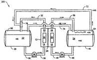
- FIG. 1is a block diagram of a vanadium redox battery energy storage system (“VRB-ESS” or “system”) 100 .
- System 100includes a plurality of cells 12 that may each have a negative compartment 14 with a negative electrode 16 and a positive compartment 18 with a positive electrode 20 .
- Suitable electrodesinclude any number of components known in the art and may include electrodes manufactured in accordance with the teachings of U.S. Pat. No. 5,665,212, which is hereby incorporated by reference.
- the negative compartment 14may include a solution 22 in electrical communication with the negative electrode 16 .
- the solution 22may be an electrolyte containing specified redox ions which are in a reduced state and are to be oxidized during the discharge process of the cell 12 , or are in an oxidized state and are to be reduced during the charging process of the cell 12 , or which are a mixture of these latter reduced ions and ions to be reduced.
- the charge-discharge redox reaction occurring at the negative electrode 16 in the solution 22may be represented by Equation 1.1: V 2+ V 3+ +e ⁇ Eq. 1.1
- the positive compartment 18contains a solution 24 in electrical communication with the positive electrode 20 .
- the solution 24may be an electrolyte containing specified redox ions which are in an oxidized state and are to be reduced during the discharge process of a cell 12 , or are in a reduced state and are to be oxidized during the charging process of the cell 12 , or which are a mixture of these oxidized ions and ions to be oxidized.
- the charge-discharge redox reaction occurring at the positive electrode 20 in the positive solution 24may be simplistically represented by Equation 1.2: V 4+ V 5+ +e ⁇ Eq. 1.2
- the solution 22 and the solution 24may be prepared in accordance with the teachings of U.S. Pat. Nos. 4,786,567, 6,143,443, 6,468,688, and 6,562,514, which are hereby incorporated by reference, or by other techniques known in the art.
- the solution 22is 1M to 6M H 2 SO 4 and includes a stabilizing agent in an amount typically in the range of from 0.1 to 20 wt %, and the solution 24 may also be 1M to 6M H 2 SO 4 .
- Each cell 12includes an ionically conducting membrane, or porous separator 26 disposed between the positive compartment 14 and the negative compartment 18 and in contact with the solution 24 and the solution 22 to provide ionic communication therebetween.
- Membrane 26serves as an ion exchange membrane and may include a carbon material which may or may not be purfluorinated.
- Membrane 26may be embodied as an anion membrane, a cation membrane or a porous diaphragm.
- the membrane 26 disposed between the negative solution 24 and the positive solution 22is designed to prevent the transport of water, vanadium and sulfate ions, typically some amount of water, vanadium and sulfate transport occurs. Consequently, after a period of time, cells 12 become imbalanced because water, vanadium, and sulfate cross over. Each cross over typically occurs in one direction (i.e., from the solution 24 to the solution 22 , or from the solution 22 to the solution 24 , depending on what type of membrane 26 is used). In order to balance system 100 , positive solution 24 and negative solution 22 may be mixed, which completely discharges the battery system 100 .
- Additional negative solution 22may be held in a negative reservoir 28 that is in fluid communication with a negative compartment 14 through a supply line 30 and a return line 32 .
- Reservoir 28may be embodied as a tank, bladder, or other container known in the art.
- the supply line 30may communicate with a pump 36 and a heat exchanger 38 .
- Pump 36enables fluid movement of the solution 22 through the reservoir 28 , the supply line 30 , the negative compartment 14 , and the return line 32 .
- Pump 36may have a variable speed to allow variance in the generated flow rate.
- the heat exchanger 38may transfer heat generated by resistive heating and chemical reactions from the solution 22 to a fluid or gas medium. Pump 36 and the heat exchanger 38 may be selected from any number of suitable devices known to those having skill in the art.
- the supply line 30may include one or more supply line valves 40 to control the volumetric flow of solution.
- the return line 32may also communicate with one or more return line valves 44 that control the return volumetric flow.
- additional catholyte solution 24may be held in catholyte reservoir 46 that is in fluid communication with the positive compartment 18 through the supply line 48 and the return line 50 .
- the supply line 48may communicate with pump 54 and heat exchanger 56 .
- Pump 54may be a variable speed pump 54 that enables flow of the solution 24 through the reservoir 46 , the supply line 48 , the positive compartment 18 , and the return line 50 .
- Supply line 48may also include a supply line valve 60
- the return line 50may include a return line valve 62 .
- a negative electrode 16 and a positive electrode 20are in electrical communication with a power source 64 and a load 66 .
- a power source switch 68may be disposed in series between power source 64 and each negative electrode 16 .
- a load switch 70may be disposed in series between load 66 and each negative electrode 16 .
- FIG. 1is provided for illustrative purposes only, as this disclosure may apply to any combination of cells forming a VRB-ESS 100 .
- a power source switch 68is closed, and a load switch 70 is opened.
- Pump 36pumps solution 22 through the negative compartment 14 , and the reservoir 28 via the supply line 30 and the return line 32 .
- pump 54pumps solution 24 through the positive compartment 18 and the reservoir 46 via the supply line 48 and the return line 50 .
- Each cell 12is charged by delivering electrical energy from a power source 64 to a negative electrode 16 and a positive electrode 20 .
- the electrical energyderives divalent vanadium ions in the solution 22 and quinvalent vanadium ions in the solution 24 .
- Electricityis drawn from each cell 12 by closing the load switch 70 and opening the power source switch 68 . This causes the load 66 , which is in electrical communication with the negative electrode 16 and the positive electrode 20 , to withdraw electrical energy.
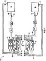
- FIGS. 2 through 4show embodiments of the disclosure as applied to a single VRB-ESS cell 12 , as shown in FIG. 1 and disclosed above. However, each embodiment may be applied to a plurality of cells 12 .
- a negative compartment 14has a negative solution 22 and a negative electrode 16 ; the negative compartment 14 is in fluid communication with a negative reservoir 28 . This is accomplished with a pump 36 pumping negative electrolyte solution 22 from the negative reservoir 28 through the negative compartment 14 and back through the return line 32 into the negative reservoir 28 .
- FIGS. 2 through 4do not include heat exchangers or valves as discussed in FIG. 1 in order to simplify the discussion, not to infer that heat exchangers and valves are not needed or desired.
- each reservoirmay have a varying amount of vent space at the top thereof where gases generated from the electrodes and solutions accumulate.
- the positive vent space 64 of the positive reservoir 46 and the negative vent space 66 of the negative reservoir 28are allowed to communicate for simplicity of operation and economy of construction. Such construction, however, allows the oxygen produced by the positive solution 24 in the positive reservoir 46 to mix with hydrogen produced by the negative solution 22 of the negative reservoir 28 , creating a potentially flammable gas mixture where positive vent space 64 and negative vent space 66 communicate.
- a feature of the VRB-ESS electrolytesis that the negative electrolyte, solution 22 , is an excellent oxygen scavenger.
- a mixed V2:V3 solution, or even a mixed V3:V4 solutionabsorbs oxygen rapidly and may reduce the oxygen level below the minimum oxygen concentration required for an explosion or flame propagation.
- the challengeis how to use the negative solution 22 in the negative reservoir 28 as a scavenger so that, at no point in the entire vent system, is the gas mixture explosive.
- Embodiments to remove oxygenmay use momentum associated with recirculating negative electrolyte ⁇ VE, to effect a local reduction in pressure in solution 22 (below the pressure in the +ve ullage), thus drawing oxygen-containing positive +VE gas through a +VE gas draw 72 and thereby scrubbing oxygen from the positive electrolyte vent space 64 .
- a corresponding volume of negative ⁇ VE gas(minus any absorbed oxygen) is returned through a balancing line 74 back into the positive vent space 64 .
- a continuous entrainment of positive +VE gas into the negative solution 22 flowcan be used to keep oxygen levels low or depleted below hazardous levels.
- FIG. 2is an embodiment 200 using a ⁇ VE electrolyte solution return line 32 siphon as an absorber, shown as applied to a single VRB cell 12 .
- Cell 12is configured so that the negative solution 22 , a fluid, “siphons” back into its reservoir 28 .
- the positive +VE gas draw 72 coming from the positive vent space 64may connect into the negative return line 32 .
- connection 76 in the return piping line 32and indeed at most points along the return line 32 , there is a lower pressure than the opposing vent space, in this case the positive vent space 64 .
- the negative solution 22 in the return line 32may draw gas from the positive vent space 64 , causing oxygen-containing positive +VE gas to pass through the +VE gas draw 72 to be scavenged by the negative solution 22 found in the negative reservoir 28 .
- system 300includes an eductor 78 , which both extracts and absorbs (or scavenges) oxygen from the positive +VE gas pulled off of the positive vent space 64 .
- Water jet eductorsutilize the kinetic energy of one liquid to cause the flow of another liquid or gas. Eductors normally consist of a converging nozzle, a body, and a diffuser. In operation, the pressure energy of the reactive motive liquid, here the negative solution 22 of the negative return line 32 , is converted to velocity energy by the converging nozzle.
- the eductor 78may be coupled to the negative return line 32 to allow negative solution 22 to pass through it, acting as the reactive motive liquid.
- the +VE gas draw 72may be connected into the body of the eductor 78 . The high velocity liquid flow of the negative solution 22 then entrains the positive +VE gas in the +VE gas draw 72 into the eductor 78 .
- Negative solution 22 in reservoir 28may scavenge any oxygen the eductor 78 may have failed to remove during the entrainment of +VE gas from the positive vent space 64 .
- the entire recirculation of the positive +VE gas stream, from the catholyte vent space 64 , through the +VE gas draw 72 , through the eductor 78 , and back through the balancing line 74takes place to feed the eductor 78 for oxygen removal.
- the pressure differential between the eductor 78 and the positive vent space 64may simply be an incidental aid to the drawing power of the eductor 78 .
- pressure differential inherent in the systemwill continue to help separate oxygen and hydrogen gases in communicated regions of vent spaces 64 and 66 .
- system 400employs an eductor 78 , but with a partial recirculation system.
- System 400includes the addition of a kick-back line 80 , which is a line split off of the negative supply line 30 and funneled back into the negative reservoir 28 .
- the eductor 78is then coupled into the kick-back line 80 with the +VE gas draw 72 connected into the body of the eductor 78 .
- the negative solution 22 of the kick-back line 80acts as the reactive motive liquid to entrain the positive +VE gas into the eductor 78 . Because only part of the negative solution 22 from supply line 30 is used as the reactive motive liquid, it is called a partial recirculation stream.
- the positive +VE gasis sucked into the eductor 78 , mixing with the negative solution 22 , which scavenges oxygen from the +VE gas before the mixture is pumped into the negative vent space 66 .
- System 400may be employed where reservoirs are common across multiple cells 12 (“tank mixing”), and where feeding negative return lines 32 into multiple eductors 78 is more difficult or expensive to manufacture.
Landscapes
- Life Sciences & Earth Sciences (AREA)
- Engineering & Computer Science (AREA)
- Manufacturing & Machinery (AREA)
- Sustainable Development (AREA)
- Sustainable Energy (AREA)
- Chemical & Material Sciences (AREA)
- Chemical Kinetics & Catalysis (AREA)
- Electrochemistry (AREA)
- General Chemical & Material Sciences (AREA)
- Fuel Cell (AREA)
Abstract
Description
V2+

V4+
Claims (10)
Priority Applications (12)
| Application Number | Priority Date | Filing Date | Title |
|---|---|---|---|
| US11/716,120US7517608B2 (en) | 2007-03-09 | 2007-03-09 | Inherently safe redox flow battery storage system |
| BRPI0721247-0ABRPI0721247A2 (en) | 2007-03-09 | 2007-06-18 | inherently safe redox battery flow storage system |
| PL07809668TPL2122718T3 (en) | 2007-03-09 | 2007-06-18 | Intrinsically safe storage system with redox flow-through accumulator |
| DK07809668.2TDK2122718T3 (en) | 2007-03-09 | 2007-06-18 | INCORRECTLY SAFE REDOX FLOW BATTERY STORAGE SYSTEM |
| PT07809668TPT2122718E (en) | 2007-03-09 | 2007-06-18 | INTRINSICALLY INSURED REDOX-FLOW BATTERY STORAGE SYSTEM |
| PCT/US2007/014277WO2008111946A1 (en) | 2007-03-09 | 2007-06-18 | Inherently safe redox flow battery storage system |
| EP07809668AEP2122718B1 (en) | 2007-03-09 | 2007-06-18 | Inherently safe redox flow battery storage system |
| CN200780050242XACN101584061B (en) | 2007-03-09 | 2007-06-18 | Inherently safe redox flow battery storage system |
| ES07809668TES2388635T3 (en) | 2007-03-09 | 2007-06-18 | Inherently safe redox flow battery storage system |
| AU2007348977AAU2007348977B2 (en) | 2007-03-09 | 2007-06-18 | Inherently safe redox flow battery storage system |
| TW096122629ATW200838022A (en) | 2007-03-09 | 2007-06-22 | Inherently safe redox flow battery storage system |
| CL200702992ACL2007002992A1 (en) | 2007-03-09 | 2007-10-18 | REDOX BATTERY STORAGE SYSTEM THAT INCLUDES CELL WITH POSITIVE AND NEGATIVE COMPARTMENTS, POSITIVE DEPOSIT WITH VENTILATION SPACE FOR POSITIVE GAS (A) THAT INCLUDES O2, ANOLITE DEPOSIT, RETURN LINE FOR NEGATIVE SOLUTION |
Applications Claiming Priority (1)
| Application Number | Priority Date | Filing Date | Title |
|---|---|---|---|
| US11/716,120US7517608B2 (en) | 2007-03-09 | 2007-03-09 | Inherently safe redox flow battery storage system |
Publications (2)
| Publication Number | Publication Date |
|---|---|
| US20080220318A1 US20080220318A1 (en) | 2008-09-11 |
| US7517608B2true US7517608B2 (en) | 2009-04-14 |
Family
ID=39741972
Family Applications (1)
| Application Number | Title | Priority Date | Filing Date |
|---|---|---|---|
| US11/716,120Active2027-06-07US7517608B2 (en) | 2007-03-09 | 2007-03-09 | Inherently safe redox flow battery storage system |
Country Status (12)
| Country | Link |
|---|---|
| US (1) | US7517608B2 (en) |
| EP (1) | EP2122718B1 (en) |
| CN (1) | CN101584061B (en) |
| AU (1) | AU2007348977B2 (en) |
| BR (1) | BRPI0721247A2 (en) |
| CL (1) | CL2007002992A1 (en) |
| DK (1) | DK2122718T3 (en) |
| ES (1) | ES2388635T3 (en) |
| PL (1) | PL2122718T3 (en) |
| PT (1) | PT2122718E (en) |
| TW (1) | TW200838022A (en) |
| WO (1) | WO2008111946A1 (en) |
Cited By (19)
| Publication number | Priority date | Publication date | Assignee | Title |
|---|---|---|---|---|
| US20100003545A1 (en)* | 2008-07-07 | 2010-01-07 | Enervault Corporation | Redox Flow Battery System for Distributed Energy Storage |
| US20110223450A1 (en)* | 2008-07-07 | 2011-09-15 | Enervault Corporation | Cascade Redox Flow Battery Systems |
| US8632903B2 (en)* | 2011-03-25 | 2014-01-21 | Sumitomo Electric Industries, Ltd. | Redox flow battery and method of operating the same |
| US8709629B2 (en) | 2010-12-22 | 2014-04-29 | Jd Holding Inc. | Systems and methods for redox flow battery scalable modular reactant storage |
| WO2014070243A1 (en)* | 2012-11-05 | 2014-05-08 | Battelle Memorial Institute | Composite separators and redox flow batteries based on porous separators |
| US8916281B2 (en) | 2011-03-29 | 2014-12-23 | Enervault Corporation | Rebalancing electrolytes in redox flow battery systems |
| US8980484B2 (en) | 2011-03-29 | 2015-03-17 | Enervault Corporation | Monitoring electrolyte concentrations in redox flow battery systems |
| WO2015095555A1 (en)* | 2013-12-19 | 2015-06-25 | Robert Bosch Gmbh | Hydrogen/bromine flow battery in which hydrogen is freely exchanged between two celi compartments |
| CN104900892A (en)* | 2014-03-03 | 2015-09-09 | 大连融科储能技术发展有限公司 | Flow battery negative electrode electrolyte sealing system and flow battery system |
| WO2015134260A1 (en)* | 2014-03-06 | 2015-09-11 | Energy Storage Systems, Inc. | Method and system to maintain electrolyte stability for all-iron redox flow batteries |
| US9269982B2 (en) | 2011-01-13 | 2016-02-23 | Imergy Power Systems, Inc. | Flow cell stack |
| US9806366B2 (en) | 2013-06-07 | 2017-10-31 | Ess Tech, Inc. | Method and system for rebalancing electrolytes in a redox flow battery system |
| US9853306B2 (en) | 2004-01-15 | 2017-12-26 | Jd Holding Inc. | System and method for optimizing efficiency and power output from a vanadium redox battery energy storage system |
| US9853454B2 (en) | 2011-12-20 | 2017-12-26 | Jd Holding Inc. | Vanadium redox battery energy storage system |
| US10003097B2 (en) | 2011-08-02 | 2018-06-19 | Vizn Energy Systems, Incorporated | Process for operating a redox flow battery system |
| US10141594B2 (en) | 2011-10-07 | 2018-11-27 | Vrb Energy Inc. | Systems and methods for assembling redox flow battery reactor cells |
| US10181615B2 (en) | 2013-06-07 | 2019-01-15 | Ess Tech, Inc. | Method and system for rebalancing electrolytes in a redox flow battery system |
| US10651492B2 (en) | 2010-06-22 | 2020-05-12 | Vrb Energy Inc. | Integrated system for electrochemical energy storage system |
| WO2023150643A1 (en)* | 2022-02-03 | 2023-08-10 | Ess Tech, Inc. | Electrolyte management for a rebalancing cell |
Families Citing this family (24)
| Publication number | Priority date | Publication date | Assignee | Title |
|---|---|---|---|---|
| CN101901937B (en)* | 2010-08-17 | 2012-07-04 | 天津久聚能源科技发展有限公司 | Cerium ion electrolyte using silver ion as anode catalyst and preparation method thereof |
| CN102244286B (en)* | 2011-06-07 | 2014-10-15 | 中国东方电气集团有限公司 | Flow battery system and repair device thereof |
| CN102306815A (en)* | 2011-08-24 | 2012-01-04 | 中国东方电气集团有限公司 | Liquid flow cell system |
| AT512184B1 (en)* | 2012-01-23 | 2013-06-15 | Cellstrom Gmbh | SYSTEM FOR ENERGY GENERATION BZW. STORAGE OF ELECTROCHEMICAL BASIS |
| US20130316199A1 (en)* | 2012-05-25 | 2013-11-28 | Deeya Energy, Inc. | Electrochemical balance in a vanadium flow battery |
| AT514391B1 (en)* | 2013-06-13 | 2015-10-15 | Cellstrom Gmbh | Redox flow battery and method of reactivation |
| CN103326049B (en)* | 2013-06-19 | 2016-03-30 | 大连融科储能技术发展有限公司 | A hydrogen discharge system for a liquid flow battery |
| WO2014207923A1 (en)* | 2013-06-28 | 2014-12-31 | 日新電機 株式会社 | Redox flow battery |
| US10326153B2 (en) | 2013-12-23 | 2019-06-18 | Robert Bosch Gmbh | System and method for returning material from the Br2 side of an H2/Br2 flow battery back after crossover |
| US20150188178A1 (en)* | 2013-12-27 | 2015-07-02 | Robert Bosch Gmbh | Safety System for a Flow Battery and Flow Battery System |
| US9722264B2 (en) | 2014-07-07 | 2017-08-01 | Unienergy Technologies, Llc | Gas management systems and methods in a redox flow battery |
| CN106229536B (en)* | 2016-08-31 | 2023-07-28 | 东方电气(成都)氢燃料电池科技有限公司 | Electrolyte balance device and flow battery having same |
| CA3045509A1 (en)* | 2016-12-16 | 2018-06-21 | Lockheed Martin Advanced Energy Storage, Llc | Flow batteries incorporating a nitroxide compound within an aqueous electrolyte solution |
| WO2018183301A1 (en)* | 2017-03-27 | 2018-10-04 | Danzi Angelo | An advanced electrolyte mixing method for all vanadium flow batteries |
| JP7121044B2 (en)* | 2017-04-28 | 2022-08-17 | イーエスエス テック インコーポレーテッド | Integrated hydrogen recycling system using pressurized multi-chamber tanks |
| US11081708B2 (en)* | 2017-11-28 | 2021-08-03 | Sumitomo Electric Industries, Ltd. | Redox flow battery |
| US20200343571A1 (en)* | 2017-12-27 | 2020-10-29 | Showa Denko K.K. | Redox flow battery |
| CN110858659B (en)* | 2018-08-24 | 2021-08-10 | 江苏泛宇能源有限公司 | Method for flow battery waste gas treatment and flow battery system |
| JP7310769B2 (en)* | 2020-09-23 | 2023-07-19 | トヨタ自動車株式会社 | fuel cell system |
| CN113130944B (en)* | 2021-03-18 | 2022-02-22 | 上海发电设备成套设计研究院有限责任公司 | Device and method for cleaning residual liquid of cell stack suitable for hydrochloric acid series flow battery |
| CN112909301A (en)* | 2021-03-26 | 2021-06-04 | 苏州辉美汽车科技有限公司 | Flow battery and charging regeneration circulating system thereof |
| JP7717503B2 (en)* | 2021-06-17 | 2025-08-04 | 三菱重工業株式会社 | Redox flow battery |
| US11923583B2 (en)* | 2021-11-08 | 2024-03-05 | Rtx Corporation | Condensation-based redox flow battery rebalancing |
| US20230387431A1 (en)* | 2022-05-25 | 2023-11-30 | Uop Llc | Filtration applications in a redox flow battery |
Citations (2)
| Publication number | Priority date | Publication date | Assignee | Title |
|---|---|---|---|---|
| US6475661B1 (en)* | 1998-01-28 | 2002-11-05 | Squirrel Holdings Ltd | Redox flow battery system and cell stack |
| US20050158615A1 (en) | 2002-02-14 | 2005-07-21 | Samuel John M.G. | Redox flow battery |
Family Cites Families (6)
| Publication number | Priority date | Publication date | Assignee | Title |
|---|---|---|---|---|
| US4786567A (en)* | 1986-02-11 | 1988-11-22 | Unisearch Limited | All-vanadium redox battery |
| WO1989005363A1 (en)* | 1987-12-10 | 1989-06-15 | Unisearch Limited | Vanadium compound dissolution processes |
| US5665212A (en)* | 1992-09-04 | 1997-09-09 | Unisearch Limited Acn 000 263 025 | Flexible, conducting plastic electrode and process for its preparation |
| MY125003A (en)* | 1993-11-17 | 2006-07-31 | Jd Holding Inc | Stabilized vanadium electrolyte solutions for all-vanadium redox cells and batteries |
| EP2320498B1 (en)* | 2005-01-28 | 2013-04-24 | Premium Power Corporation | Flow battery with electric potential neutralization |
| JP5050847B2 (en)* | 2005-05-31 | 2012-10-17 | パナソニック株式会社 | Secondary battery, power supply system using the same, and method of using the power supply system |
- 2007
- 2007-03-09USUS11/716,120patent/US7517608B2/enactiveActive
- 2007-06-18DKDK07809668.2Tpatent/DK2122718T3/enactive
- 2007-06-18PLPL07809668Tpatent/PL2122718T3/enunknown
- 2007-06-18AUAU2007348977Apatent/AU2007348977B2/ennot_activeCeased
- 2007-06-18PTPT07809668Tpatent/PT2122718E/enunknown
- 2007-06-18CNCN200780050242XApatent/CN101584061B/ennot_activeExpired - Fee Related
- 2007-06-18EPEP07809668Apatent/EP2122718B1/ennot_activeNot-in-force
- 2007-06-18WOPCT/US2007/014277patent/WO2008111946A1/ennot_activeCeased
- 2007-06-18BRBRPI0721247-0Apatent/BRPI0721247A2/ennot_activeIP Right Cessation
- 2007-06-18ESES07809668Tpatent/ES2388635T3/enactiveActive
- 2007-06-22TWTW096122629Apatent/TW200838022A/enunknown
- 2007-10-18CLCL200702992Apatent/CL2007002992A1/enunknown
Patent Citations (2)
| Publication number | Priority date | Publication date | Assignee | Title |
|---|---|---|---|---|
| US6475661B1 (en)* | 1998-01-28 | 2002-11-05 | Squirrel Holdings Ltd | Redox flow battery system and cell stack |
| US20050158615A1 (en) | 2002-02-14 | 2005-07-21 | Samuel John M.G. | Redox flow battery |
Non-Patent Citations (3)
| Title |
|---|
| International Search Report for PCT/US07/14277 filed Jun. 18, 2007, mailed on Aug. 18, 2008, 4 pgs. |
| Office Action for U.S. Appl. No. 11/234,778 from USPTO mailed Sep. 19, 2007, 16 pages. |
| Written Opinion of the International Searching Authority for PCT/US07/14277 filed Jun. 18, 2007, mailed on Aug. 18, 2008, 4 pgs. |
Cited By (35)
| Publication number | Priority date | Publication date | Assignee | Title |
|---|---|---|---|---|
| US9853306B2 (en) | 2004-01-15 | 2017-12-26 | Jd Holding Inc. | System and method for optimizing efficiency and power output from a vanadium redox battery energy storage system |
| US20100003545A1 (en)* | 2008-07-07 | 2010-01-07 | Enervault Corporation | Redox Flow Battery System for Distributed Energy Storage |
| US7820321B2 (en) | 2008-07-07 | 2010-10-26 | Enervault Corporation | Redox flow battery system for distributed energy storage |
| US20110045332A1 (en)* | 2008-07-07 | 2011-02-24 | Enervault Corporation | Redox Flow Battery System for Distributed Energy Storage |
| US20110117411A1 (en)* | 2008-07-07 | 2011-05-19 | Enervault Corporation | Redox Flow Battery System for Distributed Energy Storage |
| US20110223450A1 (en)* | 2008-07-07 | 2011-09-15 | Enervault Corporation | Cascade Redox Flow Battery Systems |
| US8785023B2 (en) | 2008-07-07 | 2014-07-22 | Enervault Corparation | Cascade redox flow battery systems |
| US8906529B2 (en) | 2008-07-07 | 2014-12-09 | Enervault Corporation | Redox flow battery system for distributed energy storage |
| US10651492B2 (en) | 2010-06-22 | 2020-05-12 | Vrb Energy Inc. | Integrated system for electrochemical energy storage system |
| US8709629B2 (en) | 2010-12-22 | 2014-04-29 | Jd Holding Inc. | Systems and methods for redox flow battery scalable modular reactant storage |
| US9269982B2 (en) | 2011-01-13 | 2016-02-23 | Imergy Power Systems, Inc. | Flow cell stack |
| US8632903B2 (en)* | 2011-03-25 | 2014-01-21 | Sumitomo Electric Industries, Ltd. | Redox flow battery and method of operating the same |
| US8980484B2 (en) | 2011-03-29 | 2015-03-17 | Enervault Corporation | Monitoring electrolyte concentrations in redox flow battery systems |
| US8916281B2 (en) | 2011-03-29 | 2014-12-23 | Enervault Corporation | Rebalancing electrolytes in redox flow battery systems |
| US10003097B2 (en) | 2011-08-02 | 2018-06-19 | Vizn Energy Systems, Incorporated | Process for operating a redox flow battery system |
| US10141594B2 (en) | 2011-10-07 | 2018-11-27 | Vrb Energy Inc. | Systems and methods for assembling redox flow battery reactor cells |
| US9853454B2 (en) | 2011-12-20 | 2017-12-26 | Jd Holding Inc. | Vanadium redox battery energy storage system |
| WO2014070243A1 (en)* | 2012-11-05 | 2014-05-08 | Battelle Memorial Institute | Composite separators and redox flow batteries based on porous separators |
| US9236620B2 (en) | 2012-11-05 | 2016-01-12 | Battelle Memorial Institute | Composite separators and redox flow batteries based on porous separators |
| US9806366B2 (en) | 2013-06-07 | 2017-10-31 | Ess Tech, Inc. | Method and system for rebalancing electrolytes in a redox flow battery system |
| US10923753B2 (en) | 2013-06-07 | 2021-02-16 | Ess Tech, Inc. | Method and system for rebalancing electrolytes in a redox flow battery system |
| US11888201B2 (en) | 2013-06-07 | 2024-01-30 | Ess Tech, Inc. | Methods and system for rebalancing electrolytes in a redox flow battery system |
| US12132241B2 (en) | 2013-06-07 | 2024-10-29 | Ess Tech, Inc. | Method and system for rebalancing electrolytes in a redox flow battery system |
| US10181615B2 (en) | 2013-06-07 | 2019-01-15 | Ess Tech, Inc. | Method and system for rebalancing electrolytes in a redox flow battery system |
| US10615442B2 (en) | 2013-06-07 | 2020-04-07 | Ess Tech, Inc. | Method and system for rebalancing electrolytes in a redox flow battery system |
| US11527771B2 (en) | 2013-06-07 | 2022-12-13 | Ess Tech, Inc. | Method and system for rebalancing electrolytes in a redox flow battery system |
| US11594749B2 (en) | 2013-12-19 | 2023-02-28 | Robert Bosch Gmbh | Hydrogen/bromine flow battery in which hydrogen is freely exchanged between two cell compartments |
| WO2015095555A1 (en)* | 2013-12-19 | 2015-06-25 | Robert Bosch Gmbh | Hydrogen/bromine flow battery in which hydrogen is freely exchanged between two celi compartments |
| CN104900892B (en)* | 2014-03-03 | 2017-10-17 | 大连融科储能技术发展有限公司 | Flow battery negative electrode electrolyte sealing system and flow battery system |
| CN104900892A (en)* | 2014-03-03 | 2015-09-09 | 大连融科储能技术发展有限公司 | Flow battery negative electrode electrolyte sealing system and flow battery system |
| AU2019203950B2 (en)* | 2014-03-06 | 2021-05-13 | Ess Tech, Inc | Method and system to maintain electrolyte stability for all-iron redox flow batteries |
| US10680268B2 (en) | 2014-03-06 | 2020-06-09 | Ess Tech, Inc. | Method and system to maintain electrolyte stability for all-iron redox flow batteries |
| US10230125B2 (en) | 2014-03-06 | 2019-03-12 | Ess Tech, Inc. | Method and system to maintain electrolyte stability for all-iron redox flow batteries |
| WO2015134260A1 (en)* | 2014-03-06 | 2015-09-11 | Energy Storage Systems, Inc. | Method and system to maintain electrolyte stability for all-iron redox flow batteries |
| WO2023150643A1 (en)* | 2022-02-03 | 2023-08-10 | Ess Tech, Inc. | Electrolyte management for a rebalancing cell |
Also Published As
| Publication number | Publication date |
|---|---|
| WO2008111946A1 (en) | 2008-09-18 |
| DK2122718T3 (en) | 2012-08-27 |
| US20080220318A1 (en) | 2008-09-11 |
| PL2122718T3 (en) | 2012-11-30 |
| EP2122718B1 (en) | 2012-06-06 |
| PT2122718E (en) | 2012-08-21 |
| EP2122718A1 (en) | 2009-11-25 |
| ES2388635T3 (en) | 2012-10-17 |
| AU2007348977A1 (en) | 2008-09-18 |
| TW200838022A (en) | 2008-09-16 |
| EP2122718A4 (en) | 2010-11-17 |
| BRPI0721247A2 (en) | 2013-01-29 |
| CL2007002992A1 (en) | 2008-02-01 |
| CN101584061A (en) | 2009-11-18 |
| AU2007348977B2 (en) | 2012-11-29 |
| CN101584061B (en) | 2011-12-07 |
Similar Documents
| Publication | Publication Date | Title |
|---|---|---|
| US7517608B2 (en) | Inherently safe redox flow battery storage system | |
| CN111244502B (en) | Integrated reversible fuel cell system and its pure gas circulation control system | |
| US20100092843A1 (en) | Venturi pumping system in a hydrogen gas circulation of a flow battery | |
| US20070072067A1 (en) | Vanadium redox battery cell stack | |
| KR20150021074A (en) | Electrochemical balance in a vanadium flow battery | |
| JP7149623B2 (en) | redox flow battery | |
| US20050164055A1 (en) | Fuel cell system and power generating method in fuel cell system | |
| CN113314733A (en) | Rebalanceable system of iron-chromium flow battery | |
| CN101300705B (en) | Water controller system having stable structure for direct methanol fuel cell | |
| JP2005197065A (en) | Fuel cell power generation method and fuel cell | |
| JP6629911B2 (en) | Redox flow battery | |
| KR20200041121A (en) | Redox flow battery | |
| JP2016051521A (en) | Fuel cell system | |
| US20200343571A1 (en) | Redox flow battery | |
| CN111834649A (en) | Rechargeable sodium-water gas fuel cell unit | |
| JP2007095400A (en) | Fuel cartridge | |
| KR100842229B1 (en) | Fuel Tanks for Fuel Cells | |
| CN210778821U (en) | Rechargeable sodium-water gas fuel cell unit | |
| AU2012365474B2 (en) | A liquid electrolyte fuel cell system | |
| JP2019186131A (en) | Fuel cell system | |
| US20190148804A1 (en) | Hybrid air-slurry flow cell battery | |
| JP5308044B2 (en) | Gas-liquid separator | |
| JP2006073214A (en) | Fuel cell | |
| JPH01102859A (en) | Electrolyte distribution method for electrolyte flow type batteries | |
| Giner et al. | Fuel Cells as Rechargeable Batteries |
Legal Events
| Date | Code | Title | Description |
|---|---|---|---|
| AS | Assignment | Owner name:VRB POWER SYSTEMS INC., CANADA Free format text:ASSIGNMENT OF ASSIGNORS INTEREST;ASSIGNORS:BRERETON, CLIVE;GENDERS, DAVID;LEPP, GARY;AND OTHERS;REEL/FRAME:019209/0869;SIGNING DATES FROM 20070308 TO 20070405 | |
| AS | Assignment | Owner name:JD HOLDING INC., CAYMAN ISLANDS Free format text:ASSIGNMENT OF ASSIGNORS INTEREST;ASSIGNOR:VRB POWER SYSTEMS INC.;REEL/FRAME:022368/0273 Effective date:20090129 Owner name:JD HOLDING INC.,CAYMAN ISLANDS Free format text:ASSIGNMENT OF ASSIGNORS INTEREST;ASSIGNOR:VRB POWER SYSTEMS INC.;REEL/FRAME:022368/0273 Effective date:20090129 | |
| STCF | Information on status: patent grant | Free format text:PATENTED CASE | |
| FPAY | Fee payment | Year of fee payment:4 | |
| REMI | Maintenance fee reminder mailed | ||
| FPAY | Fee payment | Year of fee payment:8 | |
| SULP | Surcharge for late payment | Year of fee payment:7 | |
| AS | Assignment | Owner name:VRB ENERGY INC., CAYMAN ISLANDS Free format text:CHANGE OF NAME;ASSIGNOR:JD HOLDING INC.;REEL/FRAME:046913/0407 Effective date:20180628 | |
| AS | Assignment | Owner name:VRB ENERGY INC., CAYMAN ISLANDS Free format text:RECORDATION WAS IN ERROR FOR U.S. APPL. NOS. 12/810,950 AND 13/934,046 AND THE CHANGE OF NAME SHOULD BE REMOVED;ASSIGNOR:JD HOLDING INC.;REEL/FRAME:048175/0806 Effective date:20180628 Owner name:VRB ENERGY INC., CAYMAN ISLANDS Free format text:CORRECTIVE ASSIGNMENT TO CORRECT APPLICATION NUMBERS 12/810,950 AND 13/934,046 PREVIOUSLY RECORD ON REEL 048175 FRAME 0806 HEREBY CONFIRMS CHANGE OF NAME;ASSIGNOR:JD HOLDING INC.;REEL/FRAME:048175/0806 Effective date:20180628 | |
| AS | Assignment | Owner name:VRB ENERY INC., CAYMAN ISLANDS Free format text:CORRECTIVE ASSIGNMENT TO CORRECT THE NATURE OF CONVEYANCE PREVIOUSLY RECORDED AT REEL: 048175 FRAME: 0806. ASSIGNOR(S) HEREBY CONFIRMS THE CHANGE OF NAME;ASSIGNOR:JD HOLING INC.;REEL/FRAME:048203/0459 Effective date:20180628 | |
| MAFP | Maintenance fee payment | Free format text:PAYMENT OF MAINTENANCE FEE, 12TH YR, SMALL ENTITY (ORIGINAL EVENT CODE: M2553); ENTITY STATUS OF PATENT OWNER: SMALL ENTITY Year of fee payment:12 |