US7517450B2 - Pre-assembled flow control structured and related media filtration system - Google Patents
Pre-assembled flow control structured and related media filtration systemDownload PDFInfo
- Publication number
- US7517450B2 US7517450B2US11/746,238US74623807AUS7517450B2US 7517450 B2US7517450 B2US 7517450B2US 74623807 AUS74623807 AUS 74623807AUS 7517450 B2US7517450 B2US 7517450B2
- Authority
- US
- United States
- Prior art keywords
- stormwater
- filter
- housing
- inlet
- outlet
- Prior art date
- Legal status (The legal status is an assumption and is not a legal conclusion. Google has not performed a legal analysis and makes no representation as to the accuracy of the status listed.)
- Active
Links
Images


Classifications
- B—PERFORMING OPERATIONS; TRANSPORTING
- B01—PHYSICAL OR CHEMICAL PROCESSES OR APPARATUS IN GENERAL
- B01D—SEPARATION
- B01D35/00—Filtering devices having features not specifically covered by groups B01D24/00 - B01D33/00, or for applications not specifically covered by groups B01D24/00 - B01D33/00; Auxiliary devices for filtration; Filter housing constructions
- B01D35/02—Filters adapted for location in special places, e.g. pipe-lines, pumps, stop-cocks
- B01D35/027—Filters adapted for location in special places, e.g. pipe-lines, pumps, stop-cocks rigidly mounted in or on tanks or reservoirs
- B01D35/0276—Filtering elements with a vertical rotation or symmetry axis mounted on tanks or reservoirs
- B—PERFORMING OPERATIONS; TRANSPORTING
- B01—PHYSICAL OR CHEMICAL PROCESSES OR APPARATUS IN GENERAL
- B01D—SEPARATION
- B01D29/00—Filters with filtering elements stationary during filtration, e.g. pressure or suction filters, not covered by groups B01D24/00 - B01D27/00; Filtering elements therefor
- B01D29/11—Filters with filtering elements stationary during filtration, e.g. pressure or suction filters, not covered by groups B01D24/00 - B01D27/00; Filtering elements therefor with bag, cage, hose, tube, sleeve or like filtering elements
- B01D29/13—Supported filter elements
- B01D29/15—Supported filter elements arranged for inward flow filtration
- C—CHEMISTRY; METALLURGY
- C02—TREATMENT OF WATER, WASTE WATER, SEWAGE, OR SLUDGE
- C02F—TREATMENT OF WATER, WASTE WATER, SEWAGE, OR SLUDGE
- C02F1/00—Treatment of water, waste water, or sewage
- C02F1/001—Processes for the treatment of water whereby the filtration technique is of importance
- C02F1/004—Processes for the treatment of water whereby the filtration technique is of importance using large scale industrial sized filters
- E—FIXED CONSTRUCTIONS
- E03—WATER SUPPLY; SEWERAGE
- E03F—SEWERS; CESSPOOLS
- E03F5/00—Sewerage structures
- E03F5/14—Devices for separating liquid or solid substances from sewage, e.g. sand or sludge traps, rakes or grates
- C—CHEMISTRY; METALLURGY
- C02—TREATMENT OF WATER, WASTE WATER, SEWAGE, OR SLUDGE
- C02F—TREATMENT OF WATER, WASTE WATER, SEWAGE, OR SLUDGE
- C02F2103/00—Nature of the water, waste water, sewage or sludge to be treated
- C02F2103/001—Runoff or storm water
- C—CHEMISTRY; METALLURGY
- C02—TREATMENT OF WATER, WASTE WATER, SEWAGE, OR SLUDGE
- C02F—TREATMENT OF WATER, WASTE WATER, SEWAGE, OR SLUDGE
- C02F2301/00—General aspects of water treatment
- C02F2301/04—Flow arrangements
- C02F2301/043—Treatment of partial or bypass streams
- Y—GENERAL TAGGING OF NEW TECHNOLOGICAL DEVELOPMENTS; GENERAL TAGGING OF CROSS-SECTIONAL TECHNOLOGIES SPANNING OVER SEVERAL SECTIONS OF THE IPC; TECHNICAL SUBJECTS COVERED BY FORMER USPC CROSS-REFERENCE ART COLLECTIONS [XRACs] AND DIGESTS
- Y10—TECHNICAL SUBJECTS COVERED BY FORMER USPC
- Y10T—TECHNICAL SUBJECTS COVERED BY FORMER US CLASSIFICATION
- Y10T137/00—Fluid handling
- Y10T137/402—Distribution systems involving geographic features
Definitions
- the present applicationrelates generally to systems for treating stormwater and more particularly to a pre-assembled flow control structure and related media filtration system.
- Stormwateris pure rainwater plus any particulate debris and dissolved materials that the rainwater may entrain as it traverses a surface.
- rain that falls on the roofs of buildingscollects on paved areas like driveways, roads, runways and sidewalks is typically diverted through a system of pipes, catch basins, etc. that is separate from the sewerage system.
- stormwaterhistorically has not been treated, but flowed directly from streets and gutters into natural bodies of water, e.g., rivers, lakes and the ocean.
- Stormwatercan therefore be a form of diffuse or non-point source pollution. It can entrain pollutants, such as garbage, sediment, organic matter, heavy metals, and organic toxins, and transport them into receiving natural bodies of water. As a consequence, natural bodies of water that receive stormwater may also receive the pollutants.
- pollutantssuch as garbage, sediment, organic matter, heavy metals, and organic toxins
- the amount of stormwater pollution entering into such receiving bodies of wateris related to the degree of urbanization in the surrounding area and the nature of the surrounding activities.
- Urbanizationresults in the covering of land with structures of various permeabilities, such as roadways, parking lots, and rooftops, which both generate large volumes of stormwater and accumulate pollutants. Since some of these surfaces do not allow rainfall to infiltrate, they allow the accumulated pollutants to be carried into stormwater drainage systems.
- a filter apparatus described in U.S. Pat. No. 6,027,639features a siphon-inducing mechanism.
- the filter apparatus of the '639 patentutilizes a sealed upper housing that includes a check valve for air evacuation within the housing. An induced siphon effect pulls stormwater through the filter until air is pulled through an air inlet along the lower perimeter of the housing, disrupting the siphon.
- a stormwater filtration systemincludes a stormwater containment structure including a concrete floor and a pre-assembled flow structure embedded in the concrete floor.
- the pre-assembled flow structureincludes an inlet compartment housing, an outlet compartment housing and at least one filter conduit positioned between the inlet compartment housing and the outlet compartment housing and in flow communication with the interior of the outlet compartment housing.
- At least one bypass conduitextends from the inlet compartment housing to the outlet compartment housing for delivering water from the interior of the inlet compartment housing to the interior of the outlet compartment housing.
- a plurality of filter unitsare connected to the filter conduit so that stormwater filtered by the filter units passes into the filter conduit and then to the interior of the outlet compartment housing.
- a flow assemblyfor use in forming a floor of a stormwater filtration chamber for containing multiple filter units.
- the flow assemblyincludes a first housing forming a stormwater inlet compartment, a second housing forming a stormwater outlet compartment and a plurality of filter conduits.
- Each filter conduithas a first end connected to the first housing in a manner that prevents stormwater from flowing from the inlet compartment into the first end and a second end connected to the second housing in a manner that permits stormwater to flow from the second end into the outlet compartment.
- a plurality of filter connection point structuresextend upwardly from the filter conduit.
- a plurality of bypass conduitshave a first end connected to the first housing in a manner that permits stormwater to flow from the inlet compartment into the first end and a second end connected to the second housing in a manner that permits stormwater to flow from the second end into the outlet compartment.
- a method of manufacturing a stormwater filtration chamberincludes producing a flow assembly having a first housing forming a stormwater inlet compartment and a second housing forming a stormwater outlet compartment.
- At least one filter conduithas a first end and a second end, where the first end is connected to the first housing in a manner that prevents stormwater from flowing from the inlet compartment into the first end and the second end is connected to the second housing in a manner that permits stormwater to flow from the second end into the outlet compartment.
- the filter conduitfurther includes a plurality of filter connection point structures extending therefrom. At least one bypass conduit having a first end and a second end is provided.
- the first end of the bypass conduitis connected to the first housing in a manner that permits stormwater to flow from the inlet compartment into the first end, and the second end is connected to the second housing in a manner that permits stormwater to flow from the second end into the outlet compartment.
- the flow assemblyis embedded in concrete to produce a floor for the filtration chamber.
- a stormwater treatment systemin a fourth aspect, includes a stormwater containment structure including a floor.
- a pre-assembled flow control structureforms at least part of the floor.
- the pre-assembled flow control structureincludes an inlet portion, an outlet portion and a treatment region extending between the inlet portion and the outlet portion.
- the treatment regionincludes a filter conduit for directing filtered stormwater toward the outlet portion and a bypass conduit for directing unfiltered stormwater from an inlet reservoir at the inlet portion toward the outlet portion.
- Filter cartridgesare connected to the filter conduit and in communication therewith so that filtered stormwater exiting the filter cartridges flows into the filter conduit and is directed toward the outlet portion.
- FIG. 1is a diagrammatic, section view of an embodiment of a stormwater treatment system including pre-assembled flow control structure in an initial, bypass configuration;
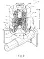
- FIG. 2is a diagrammatic section view of the stormwater treatment system of FIG. 1 with the pre-assembled flow control structure in a filtering configuration;
- FIG. 3is a perspective view of the pre-assembled flow control structure of FIG. 1 in isolation;
- FIG. 4is a perspective view of the pre-assembled flow control structure of FIG. 3 with filter assemblies connected thereto and being changed to its filtering configuration;
- FIGS. 5 and 6are perspective views of the pre-assembled flow control structure of FIGS. 3 and 4 in a different configuration
- FIG. 7is a perspective view of the flow control assembly of FIG. 3 incorporated into a floor of a containment structure
- FIG. 8is a section view of an embodiment of a filter assembly for use with the stormwater treatment system of FIG. 1 ;
- FIG. 9is a perspective view of another embodiment of a pre-assembled flow control structure.
- a stormwater treatment system 10includes a vault 12 having an access opening 14 at a top 16 of the vault through which access can be gained to an interior 24 of the vault (e.g., by removing cover 18 ) and a floor 20 that, in the illustrated embodiment, is formed of concrete.
- the stormwater treatment system 10further includes an inlet 26 through which stormwater enters the vault 12 and an outlet 28 through which stormwater exits the vault.
- a manifold of filter assemblies 22are located in the interior 24 of the vault 12 for use in filtering stormwater entering through the inlet.
- the filter assemblies 22are connected to and in communication with a pre-assembled flow control structure 30 that directs filtered stormwater toward the outlet 28 .
- the pre-assembled flow control structure 30includes an inlet region 32 , an outlet region 34 and a primary treatment region 36 extending between the inlet and outlet regions.
- the pre-assembled flow control structure 30is incorporated into the concrete of the floor 20 thereby being an integral part of the floor.
- the pre-assembled flow control structure 30 of FIG. 1is shown in an initial, bypass configuration where stormwater bypasses the filter assemblies 22 , for example, during a site construction phase.
- the pre-assembled flow control structure 30includes an inlet conduit 38 in communication with the inlet 26 .
- the inlet conduit 38includes a removable upper section 40 , 40 ′ that can be separated from a lower section 42 .
- the lower section 42 of the inlet conduit 38may be connected to an inlet reservoir 44 that receives stormwater from the inlet conduit.
- a filter conduit 46is connected to the inlet reservoir 44 at a first end and is connected to an outlet reservoir 48 at a second, opposite end.
- the outlet reservoir 48receives stormwater from the filter conduit 46 , which then flows out of the vault 12 through the outlet 28 .
- a overflow conduit 50is connected to the outlet reservoir 48 . In this initial, bypass configuration, the overflow conduit 50 may be closed so that stormwater cannot flow out of or into the overflow conduit.
- stormwaterenters through the inlet 26 , flows directly into the inlet conduit 38 and into the inlet reservoir 44 . From the inlet reservoir 44 , the stormwater enters the filter conduit 46 (or other conduit) and flows to the outlet reservoir 48 . The stormwater then exits through the outlet 28 from the outlet reservoir 48 .
- This initial bypass configurationallows for stormwater to bypass the filter conduits, for example, during a site construction phase when the amount of sediment and other particles in the stormwater can be relatively elevated. Additionally, bypass structure is located within the vault 12 as opposed to external of the vault, which can reduce cost as there may be no need for additional pipes and other structures and less concrete used.
- the pre-assembled flow control structureis shown in a filtering configuration.
- the upper section 40 , 40 ′ of the inlet conduit 38is removed and an energy dissipator structure 52 is connected to the inlet conduit.
- the energy dissipator structure 52prevents stormwater from entering the lower section 42 of the inlet conduit 38 and disperses the energy of the stormwater as it comes into contact with the dissipator structure.
- the overflow conduit 50is opened to allow stormwater to bypass the filter assemblies 22 when the water level reaches a bypass elevation within the vault 12 .
- stormwaterenters through the inlet 26 and falls onto the dissipator structure 52 .
- the dissipator structure 52disperses the energy of the stormwater as it falls and directs the stormwater toward the primary treatment region 36 of the pre-assembled flow control structure 30 .
- the stormwaterthen enters the filter assemblies 22 and is filtered as the stormwater moves through filter media 54 .
- the filtered stormwaterthen exits the filter assemblies 22 and enters the filter conduit 46 where the filtered stormwater is directed to the outlet reservoir 48 and outlet 28 .
- the stormwater level within the vault 12may rise to the bypass elevation. In these instances, some stormwater may flow into the overflow conduit 50 and into the outlet 28 , thereby bypassing the filter assemblies 22 .
- the pre-assembled flow control structure 30is shown in isolation, for example, prior to incorporating the pre-assembled flow control structure into concrete and connecting the filter assemblies 22 .
- the pre-assembled flow control structure 30includes an inlet reservoir housing 56 having the inlet reservoir 44 , an outlet reservoir housing 58 having the outlet reservoir 48 and conduits including the filter conduits 46 and bypass conduits 60 connecting the inlet reservoir housing and the outlet reservoir housing.
- the inlet conduit 38is connected to the inlet reservoir housing 56 at a side portion 62 , for example, to accommodate a vault inlet that is located thereby.
- the pre-assembled flow control structure 30is configured to accommodate different configurations by including multiple openable connection locations 64 and 66 .
- Each connecting location 64 , 66includes a removable cover 68 that, once removed, exposes an opening to the inlet reservoir 44 and allows for connection of the inlet conduit 38 to the corresponding connection location.
- the overflow conduit 50is connected to the outlet reservoir housing 58 at a side portion 70 to accommodate the vault outlet.
- the pre-assembled flow control structure 30is configured to accommodate different configurations by including multiple openable connection locations 72 and 74 that also include removable covers 76 . Once the removable covers 76 are removed, an opening is exposed to the outlet reservoir 48 that allows for connection of the bypass conduit thereto, for example, to accommodate a vault outlet located thereby.
- the inlet conduit 38 and the overflow conduit 50may not be part of the pre-assembled flow control structure 30 and may be connected to the inlet and outlet reservoir housings 56 and 58 after the pre-assembled flow control structure is embedded in concrete.
- the inlet reservoir housing 56 and the outlet reservoir housing 58each include detents 78 for providing increased strength.
- one or both of the inlet and outlet reservoir housings 56 and 58include deck stub mounting holes 80 a for connecting a filter assembly 22 thereto. Providing the inlet and/or outlet reservoir housings 56 , 58 with deck stub mounting holes 80 a can increase the number of filter assemblies that can be placed within the vault, which can increase the throughput of filtered stormwater through the treatment system.
- Each filter conduit 46includes deck stub mounts 80 b that extend vertically upward from an upper surface 82 of the filter conduit.
- the filter conduits (and the bypass conduits 60 )are rectangular in cross-section, however, they may be any other suitable shape such as circular in cross-section.
- the deck stub mounts 80 bare used to connect a filter assembly 22 thereto.
- the filter conduits 46are used to direct only filtered stormwater passing through the filter assemblies 22 to the outlet reservoir 48 with the pre-assembled flow control structure 30 in the filtering configuration.
- the filter conduitsmay direct unfiltered stormwater to the outlet reservoir 48 during the initial bypass configuration.
- none of the bypass conduits 60include the deck stub mounts 80 b .
- bypass conduits 60are used to direct stormwater to the outlet reservoir 48 only during the initial, bypass configuration. In other embodiments, the bypass conduits 60 may direct filtered stormwater to the outlet reservoir 48 with the pre-assembled flow control structure 30 in the filtering configuration.
- the pre-assembled flow control structure 30is shown with filter assemblies 22 connected thereto. Also, in FIG. 4 , the pre-assembled flow control structure 30 is shown being converted from its initial, bypass configuration to its filtering configuration by removing the upper section 40 ′ of the inlet conduit 38 and attaching the flow dissipator structure 52 . As noted above, the filter assemblies 22 are not confined only to the primary treatment region 36 , but may also be located in the inlet and outlet regions 32 and 34 . Use of the inlet conduit 38 , the overflow conduit 50 , inlet reservoir housing 56 and outlet reservoir housing 58 eliminates need for baffling structures, for example, to define a forebay and an overflow bay by dividing the vault into separate volumes.
- FIGS. 5 and 6illustrate a different pre-assembled flow control structure configuration where the inlet and overflow conduits 38 and 50 are at end locations 64 and 72 , respectively. Additionally, a height of the inlet conduit 38 and/or outlet conduit 50 is increased, for example, to accommodate taller filter assembly 22 heights, for example, as compared to the configuration of FIG. 4 . Increasing the height of the inlet conduit 38 can be accomplished, for example, through the addition of conduit sections 84 - 87 .
- the pre-assembled flow control structure 30may be formed by any suitable method.
- the inlet reservoir housing 56 , the outlet reservoir housing 58 and the conduits 46 , 60are formed separately and then connected together.
- the inlet and outlet reservoir housings 56 , 58may be molded from a suitable plastic material such as ABS and the conduits 46 , 60 may be molded or extruded from the same or a different plastic material such as PVC.
- the flow control structure 30is “pre-assembled” in that it can be fully assembled before it is incorporated into the concrete of the vault floor thereby being an integral part of the floor.
- the pre-assembled flow control structure 30is shown incorporated into the concrete 88 of the floor 20 (see also FIGS. 1 and 2 ) without the filter assemblies 22 connected thereto.
- the deck stub mounts 80 b and upper surfaces 90 and 92 of the inlet reservoir housing 56 and outlet reservoir housing 58 , respectively,are exposed at the surface of the floor 20 . This exposure allows for connection (and, in some instances, relocation) of the inlet conduit 38 , overflow conduit 50 and/or filter assemblies 22 to the pre-assembled flow control structure.
- the pre-assembled flow control structure 30is located within the vault and then the concrete is poured over the pre-assembled flow control structure as shown thereby forming the floor 20 of the vault. Then, the filter assemblies 22 are connected to the deck stub mounts 80 b.
- the filter assemblies 22are connected to the mounts 80 a and 80 b within the vault and then the structure is then transported to the site. This can provide more reliable installation of the cartridges prior to delivery to the site.
- a filter assembly 22includes a hood 100 connected to a perforated or mesh center tube 102 having a drainage space 104 extending therethrough using an inner drainage space cap 106 that engages an upward extending end of the center tube.
- Inner drainage space cap 106contains a mechanism (e.g., a one-way check valve) to promote the development of a siphon by permitting air to be expelled from beneath the hood 100 but preventing air from flowing back into the filter assembly 22 through the inner drainage space cap.
- Center tube 102is connected to a bottom pan 108 that forms a base for the filter assembly 22 .
- a permeable outer screen 110rests on the bottom pan 108 , the outer screen extending vertically upward from the bottom pan and defining an annular volume between the center tube 102 and the outer screen.
- Flow through the filter assemblyis controlled by a float valve assembly 112 that includes a buoyant float 114 , a float valve body 116 and a linkage 118 joining the buoyant float and the float valve body.
- the float valve assembly 112impedes or limits passage of stormwater from the filter assembly 22 when it is in its lowered position as illustrated.
- Filter media 54is located within the annular volume between the center tube 102 and the outer screen 110 .
- the filter mediahas a height of more than about 18 inches, such as about 27 inches or more.
- the filter assembly 22generally relies on hydraulic pressure to initially force water through the filter media and the filter assembly is therefore at least partially submerged in stormwater during normal operation. As stormwater enters the filter assembly, infiltrates radially inward through the outer screen 110 and filter media 54 , and into the drainage space, filtration occurs as the stormwater is strained through and comes into contact with the filter media.
- General operation of the filter assembly including siphonis similar to that described in pending U.S. Pat. Ser. No. 10/647,102, filed Aug.
- the filter media 54may be selected to efficiently remove contaminants by physical filtration. Additionally, the filter media may be selected to remove contaminants through mechanical action, chemical action, biological action, or by any suitable combination thereof.
- a screensuch as outer screen 110 is a satisfactory physical filter without the presence of additional filter media.
- the filter assemblymay be capable of high throughput, rapidly screening debris from large volumes of stormwater.
- the filterincludes outer screen 110 and one or more types of filter medium that is selected for finer filtration, for appropriate chemical reactivity, or appropriate biological activity. Mixtures of different media types are optionally used to provide advantageous combinations of filtering ability.
- the filter media 54may be selected to remove heavy metals, oils and greases, organic toxins, and other contaminants that stormwater typically accumulates when flowing over paved areas in residential or industrial communities before entry into a stormwater treatment system. Alternatively, or in addition, the filter media 54 is selected to remove total or dissolved phosphorous or nitrogen from stormwater. Selected media include, without limitation, organic compost, vermiculite, activated carbon, peat, zeolite, perlite, diatomaceous earth, clay minerals, commercial ion exchange resins, catalyst-infused resins, silica sand, iron-infused media, or mixtures of these.
- the filter media 54may be in the form of granules or pellets.
- the filter assembly 22optionally includes a cloth or paper filter, including pleated filters.
- a cloth or paper filtereither outside of or within the filter medium basket may be used to capture extremely fine particulates during filtration.
- outer screen 54is shown generally as a right circular cylinder in the illustrated embodiment, other configurations are contemplated.
- an outer screen with an undulating, wavelike shapecould be used to increase the filter surface area.
- a flow control structure 120is illustrated that includes many of the components described above, such as filter conduits 46 , outlet compartment housing 58 and overflow structure 50 , but does not include an inlet compartment housing.
- the flow control structure 120also includes flume spacers 122 used to maintain an alignment of the conduits. Accordingly, other embodiments are contemplated and modifications and changes could be made without departing from the scope of this application as expressed by any claims now included or hereafter added.
Landscapes
- Chemical & Material Sciences (AREA)
- Chemical Kinetics & Catalysis (AREA)
- Life Sciences & Earth Sciences (AREA)
- Engineering & Computer Science (AREA)
- Hydrology & Water Resources (AREA)
- Water Supply & Treatment (AREA)
- Health & Medical Sciences (AREA)
- Public Health (AREA)
- Environmental & Geological Engineering (AREA)
- Organic Chemistry (AREA)
- Revetment (AREA)
- Structure Of Emergency Protection For Nuclear Reactors (AREA)
Abstract
Description
Claims (32)
Priority Applications (6)
| Application Number | Priority Date | Filing Date | Title |
|---|---|---|---|
| US11/746,238US7517450B2 (en) | 2007-05-09 | 2007-05-09 | Pre-assembled flow control structured and related media filtration system |
| CA2686415ACA2686415C (en) | 2007-05-09 | 2008-04-24 | Pre-assembled flow control structure and related media filtration system |
| EP08746771AEP2175957B8 (en) | 2007-05-09 | 2008-04-24 | Pre-assembled flow control structure and related media filtration system |
| MX2009012058AMX2009012058A (en) | 2007-05-09 | 2008-04-24 | Pre-assembled flow control structure and related media filtration system. |
| PCT/US2008/061410WO2008140913A1 (en) | 2007-05-09 | 2008-04-24 | Pre-assembled flow control structure and related media filtration system |
| PL08746771TPL2175957T3 (en) | 2007-05-09 | 2008-04-24 | Pre-assembled flow control structure and related media filtration system |
Applications Claiming Priority (1)
| Application Number | Priority Date | Filing Date | Title |
|---|---|---|---|
| US11/746,238US7517450B2 (en) | 2007-05-09 | 2007-05-09 | Pre-assembled flow control structured and related media filtration system |
Publications (2)
| Publication Number | Publication Date |
|---|---|
| US20080277326A1 US20080277326A1 (en) | 2008-11-13 |
| US7517450B2true US7517450B2 (en) | 2009-04-14 |
Family
ID=39577936
Family Applications (1)
| Application Number | Title | Priority Date | Filing Date |
|---|---|---|---|
| US11/746,238ActiveUS7517450B2 (en) | 2007-05-09 | 2007-05-09 | Pre-assembled flow control structured and related media filtration system |
Country Status (6)
| Country | Link |
|---|---|
| US (1) | US7517450B2 (en) |
| EP (1) | EP2175957B8 (en) |
| CA (1) | CA2686415C (en) |
| MX (1) | MX2009012058A (en) |
| PL (1) | PL2175957T3 (en) |
| WO (1) | WO2008140913A1 (en) |
Cited By (12)
| Publication number | Priority date | Publication date | Assignee | Title |
|---|---|---|---|---|
| US20060016767A1 (en)* | 2004-07-23 | 2006-01-26 | I.S.C. Environmental, Inc. | Fluid filter system and related method |
| US20090045128A1 (en)* | 2007-08-15 | 2009-02-19 | Christopher Adam Murray | Filter For Removing Sediment From Water |
| US20100206790A1 (en)* | 2009-02-19 | 2010-08-19 | James Ferguson Holtz | Stormwater treatment system with flow distribution overflow/bypass tray |
| US20110127204A1 (en)* | 2008-05-09 | 2011-06-02 | Hydro International Plc | Stormwater Gully |
| USD643089S1 (en)* | 2010-09-03 | 2011-08-09 | General Foam Plastics Corporation | Filtration system |
| US8221618B2 (en)* | 2007-08-15 | 2012-07-17 | Monteco Ltd. | Filter for removing sediment from water |
| US8287726B2 (en) | 2007-08-15 | 2012-10-16 | Monteco Ltd | Filter for removing sediment from water |
| US20140042103A1 (en)* | 2012-08-08 | 2014-02-13 | Kristar Enterprises, Inc. | Storm Water Filtration System Using Box Culverts |
| US9352978B2 (en) | 2013-05-29 | 2016-05-31 | Gunderson Llc | Treatment of storm water |
| US9540799B2 (en) | 2009-04-08 | 2017-01-10 | Oldcastle Precast, Inc. | Modular storm water filtration system |
| US20220023778A1 (en)* | 2020-07-27 | 2022-01-27 | Pre-Con Products | Double-Filter Basket for StormWater Retention System Drain |
| US11420880B2 (en) | 2017-10-18 | 2022-08-23 | Oldcastle Infrastructure, Inc. | Stormwater filtration system with internal bypass pipe |
Families Citing this family (9)
| Publication number | Priority date | Publication date | Assignee | Title |
|---|---|---|---|---|
| US8298419B2 (en)* | 2010-03-25 | 2012-10-30 | Puradyn Filter Technologies, Inc. | Multi filter lubricant purification system |
| US7638066B1 (en)* | 2008-06-19 | 2009-12-29 | Contech Stormwater Solutions Inc. | Flow control structure and related media filtration system |
| AU2012204148B2 (en)* | 2010-03-25 | 2014-10-02 | Puradyn Filter Technologies Inc. | Multi filter lubricant purification system |
| US9604160B2 (en)* | 2013-12-31 | 2017-03-28 | Bio Clean Environmental Services, Inc | Partitioned water treatment systems with vertical filtration units |
| US20170348620A1 (en)* | 2016-06-01 | 2017-12-07 | Omnitek Partners Llc | Modular Contaminant Filtering System For Rain Water Run-Off, Emergency Spills, and Isolated Regular Discharge Flows |
| GB2570366B (en)* | 2018-01-26 | 2020-03-18 | Ne Innovations Ltd | Pod and dispensing method |
| AU2018430735B2 (en)* | 2018-07-04 | 2024-07-11 | Holcim (Australia) Pty Ltd | A water treatment device |
| US10882759B1 (en)* | 2019-11-14 | 2021-01-05 | Advanced Drainage Systems, Inc. | Systems and methods for stormwater management |
| WO2025029246A1 (en)* | 2023-07-28 | 2025-02-06 | Solidification Products International, Inc. | Mobile liquid contaminate separator |
Citations (16)
| Publication number | Priority date | Publication date | Assignee | Title |
|---|---|---|---|---|
| US272881A (en)* | 1883-02-27 | Apparatus for | ||
| US5433845A (en)* | 1994-06-03 | 1995-07-18 | Newberry Tanks & Equipment, Inc. | Flow control bypass basin apparatus |
| WO1997041068A1 (en) | 1996-04-30 | 1997-11-06 | Stormwater Treatment Llc | Apparatus and method for treating storm water runoff |
| US6077448A (en)* | 1996-10-07 | 2000-06-20 | Wilkinson Heavy Precast | Oil/grit interceptor |
| US6077423A (en) | 1997-09-22 | 2000-06-20 | Swaf, Inc. | Combination above grade automatic stormwater separation filtration system and method of separation and filtration |
| US6231758B1 (en) | 1998-02-18 | 2001-05-15 | Abtech Industries, Inc. | Curb-inlet storm drain systems for filtering trash and hydrocarbons |
| US6251269B1 (en) | 1999-03-18 | 2001-06-26 | Dennis J. Johnson | Modular filtration system having removable filter element |
| US6350374B1 (en) | 2000-01-19 | 2002-02-26 | Jensen Enterprises, Inc. | Stormwater treatment apparatus |
| US6524473B2 (en)* | 1998-04-01 | 2003-02-25 | J. Kelly Williamson | Gravitational separator and drainwater treatment system for use in a horizontal passageway |
| US6533941B2 (en) | 2001-08-14 | 2003-03-18 | George R. Butler | Flow through drain filter for a stormwater or wastewater catch basin |
| US20030094407A1 (en) | 2001-11-20 | 2003-05-22 | Stormwater Management, Inc. | Filter cartridge with regulated surface cleaning mechanism |
| US6638424B2 (en) | 2000-01-19 | 2003-10-28 | Jensen Enterprises | Stormwater treatment apparatus |
| US6793811B1 (en)* | 2002-04-10 | 2004-09-21 | Charles R. Fleischmann | Runoff drain filter with separately removable cartridges |
| WO2005012183A2 (en) | 2003-07-28 | 2005-02-10 | Cds Technologies, Inc. | Stormwater treatment system |
| US20060016767A1 (en)* | 2004-07-23 | 2006-01-26 | I.S.C. Environmental, Inc. | Fluid filter system and related method |
| US20060207922A1 (en) | 2005-03-21 | 2006-09-21 | Dussich George V A I | Storm water filtration system |
- 2007
- 2007-05-09USUS11/746,238patent/US7517450B2/enactiveActive
- 2008
- 2008-04-24CACA2686415Apatent/CA2686415C/enactiveActive
- 2008-04-24WOPCT/US2008/061410patent/WO2008140913A1/enactiveApplication Filing
- 2008-04-24PLPL08746771Tpatent/PL2175957T3/enunknown
- 2008-04-24EPEP08746771Apatent/EP2175957B8/enactiveActive
- 2008-04-24MXMX2009012058Apatent/MX2009012058A/enactiveIP Right Grant
Patent Citations (21)
| Publication number | Priority date | Publication date | Assignee | Title |
|---|---|---|---|---|
| US272881A (en)* | 1883-02-27 | Apparatus for | ||
| US5433845A (en)* | 1994-06-03 | 1995-07-18 | Newberry Tanks & Equipment, Inc. | Flow control bypass basin apparatus |
| WO1997041068A1 (en) | 1996-04-30 | 1997-11-06 | Stormwater Treatment Llc | Apparatus and method for treating storm water runoff |
| US5707527A (en)* | 1996-04-30 | 1998-01-13 | Stormwater Treatment Llc | Apparatus and method for treating storm water runoff |
| US6077448A (en)* | 1996-10-07 | 2000-06-20 | Wilkinson Heavy Precast | Oil/grit interceptor |
| US6077423A (en) | 1997-09-22 | 2000-06-20 | Swaf, Inc. | Combination above grade automatic stormwater separation filtration system and method of separation and filtration |
| US6171507B1 (en) | 1997-09-22 | 2001-01-09 | Swaf, Inc. | Combination above grade automatic method of stormwater separation and filtration |
| US6231758B1 (en) | 1998-02-18 | 2001-05-15 | Abtech Industries, Inc. | Curb-inlet storm drain systems for filtering trash and hydrocarbons |
| US6524473B2 (en)* | 1998-04-01 | 2003-02-25 | J. Kelly Williamson | Gravitational separator and drainwater treatment system for use in a horizontal passageway |
| US6251269B1 (en) | 1999-03-18 | 2001-06-26 | Dennis J. Johnson | Modular filtration system having removable filter element |
| US6350374B1 (en) | 2000-01-19 | 2002-02-26 | Jensen Enterprises, Inc. | Stormwater treatment apparatus |
| US6638424B2 (en) | 2000-01-19 | 2003-10-28 | Jensen Enterprises | Stormwater treatment apparatus |
| US7001527B2 (en) | 2000-01-19 | 2006-02-21 | Jensen Enterprises | Stormwater treatment apparatus and method |
| US6533941B2 (en) | 2001-08-14 | 2003-03-18 | George R. Butler | Flow through drain filter for a stormwater or wastewater catch basin |
| US20030094407A1 (en) | 2001-11-20 | 2003-05-22 | Stormwater Management, Inc. | Filter cartridge with regulated surface cleaning mechanism |
| US6649048B2 (en)* | 2001-11-20 | 2003-11-18 | Stormwater Management | Filter cartridge with regulated surface cleaning mechanism |
| US6793811B1 (en)* | 2002-04-10 | 2004-09-21 | Charles R. Fleischmann | Runoff drain filter with separately removable cartridges |
| WO2005012183A2 (en) | 2003-07-28 | 2005-02-10 | Cds Technologies, Inc. | Stormwater treatment system |
| US6998038B2 (en) | 2003-07-28 | 2006-02-14 | Cds Technologies, Inc. | Stormwater treatment system |
| US20060016767A1 (en)* | 2004-07-23 | 2006-01-26 | I.S.C. Environmental, Inc. | Fluid filter system and related method |
| US20060207922A1 (en) | 2005-03-21 | 2006-09-21 | Dussich George V A I | Storm water filtration system |
Non-Patent Citations (1)
| Title |
|---|
| PCT, International Search Report and Written Opinion issued regarding PCT/US2008/061410 (Jul. 21, 2008). |
Cited By (19)
| Publication number | Priority date | Publication date | Assignee | Title |
|---|---|---|---|---|
| US7799235B2 (en)* | 2004-07-23 | 2010-09-21 | Contech Stormwater Solutions, Inc. | Fluid filter system and related method |
| US20060016767A1 (en)* | 2004-07-23 | 2006-01-26 | I.S.C. Environmental, Inc. | Fluid filter system and related method |
| US20110062088A1 (en)* | 2004-07-23 | 2011-03-17 | Olson Norman L | Fluid filter system and related method |
| US8287726B2 (en) | 2007-08-15 | 2012-10-16 | Monteco Ltd | Filter for removing sediment from water |
| US20090045128A1 (en)* | 2007-08-15 | 2009-02-19 | Christopher Adam Murray | Filter For Removing Sediment From Water |
| US8123935B2 (en)* | 2007-08-15 | 2012-02-28 | Monteco Ltd. | Filter for removing sediment from water |
| US8221618B2 (en)* | 2007-08-15 | 2012-07-17 | Monteco Ltd. | Filter for removing sediment from water |
| US10626592B2 (en) | 2008-01-16 | 2020-04-21 | Contech Engineered Solutions LLC | Filter for removing sediment from water |
| US20110127204A1 (en)* | 2008-05-09 | 2011-06-02 | Hydro International Plc | Stormwater Gully |
| US8480887B2 (en)* | 2008-05-09 | 2013-07-09 | Hydro International Plc | Stormwater gully |
| US7833412B2 (en)* | 2009-02-19 | 2010-11-16 | Americast, Inc. | Stormwater treatment system with flow distribution overflow/bypass tray |
| US20100206790A1 (en)* | 2009-02-19 | 2010-08-19 | James Ferguson Holtz | Stormwater treatment system with flow distribution overflow/bypass tray |
| US9540799B2 (en) | 2009-04-08 | 2017-01-10 | Oldcastle Precast, Inc. | Modular storm water filtration system |
| USD643089S1 (en)* | 2010-09-03 | 2011-08-09 | General Foam Plastics Corporation | Filtration system |
| US20140042103A1 (en)* | 2012-08-08 | 2014-02-13 | Kristar Enterprises, Inc. | Storm Water Filtration System Using Box Culverts |
| US9352978B2 (en) | 2013-05-29 | 2016-05-31 | Gunderson Llc | Treatment of storm water |
| US11420880B2 (en) | 2017-10-18 | 2022-08-23 | Oldcastle Infrastructure, Inc. | Stormwater filtration system with internal bypass pipe |
| US20220023778A1 (en)* | 2020-07-27 | 2022-01-27 | Pre-Con Products | Double-Filter Basket for StormWater Retention System Drain |
| US11980835B2 (en)* | 2020-07-27 | 2024-05-14 | Foley Products Company, Llc | Double-filter basket for stormwater retention system drain |
Also Published As
| Publication number | Publication date |
|---|---|
| MX2009012058A (en) | 2010-01-25 |
| PL2175957T3 (en) | 2013-03-29 |
| EP2175957B8 (en) | 2012-11-21 |
| CA2686415A1 (en) | 2008-11-20 |
| US20080277326A1 (en) | 2008-11-13 |
| EP2175957B1 (en) | 2012-10-17 |
| CA2686415C (en) | 2015-11-10 |
| EP2175957A1 (en) | 2010-04-21 |
| WO2008140913A1 (en) | 2008-11-20 |
Similar Documents
| Publication | Publication Date | Title |
|---|---|---|
| US7517450B2 (en) | Pre-assembled flow control structured and related media filtration system | |
| US12281035B2 (en) | Horizontal flow biofilter system and method of use thereof | |
| US6649048B2 (en) | Filter cartridge with regulated surface cleaning mechanism | |
| US8658044B2 (en) | Stormwater filtration apparatus, system and method | |
| CA2686450C (en) | Stormwater filter assembly | |
| US8512555B1 (en) | Filter assembly, system and method | |
| KR100706269B1 (en) | Non-point pollutant purification device for early rainfall runoff | |
| US8940170B2 (en) | Triple-chambered wetland biofilter treatment system | |
| KR100854314B1 (en) | Initial excellent treatment facility | |
| US7820040B2 (en) | Water pollution trap and methods of use thereof | |
| KR20150114224A (en) | infiltration institution of rainwater in rainwater treatment | |
| KR100904081B1 (en) | Filtration channel for reducing non-point pollutants with bypass channel | |
| KR100814790B1 (en) | Filtration channel for reducing nonpoint pollutants | |
| KR100949388B1 (en) | Purification equipment for a city and draining system using thereof | |
| KR101888850B1 (en) | Apparatus for Treatment Rainwater Using Buoyancy Member | |
| US11926548B2 (en) | Flow control riser within a stormwater treatment system | |
| US20240246841A1 (en) | Flow control riser within a stormwater treatment system |
Legal Events
| Date | Code | Title | Description |
|---|---|---|---|
| AS | Assignment | Owner name:CONTECH STORMWATER SOLUTIONS, INC., OHIO Free format text:ASSIGNMENT OF ASSIGNORS INTEREST;ASSIGNORS:HERSEY, CHRISTOPHER S.;BYRNE, GREGORY W., JR.;ABERLE, DANIEL W.;REEL/FRAME:019309/0202 Effective date:20070502 | |
| STCF | Information on status: patent grant | Free format text:PATENTED CASE | |
| AS | Assignment | Owner name:WELLS FARGO BANK, N.A., NORTH CAROLINA Free format text:SECURITY AGREEMENT;ASSIGNORS:CONTECH CONSTRUCTION PRODUCTS, INC.;CONTECH BRIDGE SOLUTIONS INC.;CDS TECHNOLOGIES, INC.;AND OTHERS;REEL/FRAME:025026/0472 Effective date:20100720 | |
| AS | Assignment | Owner name:CONTECH STORMWATER SOLUTIONS LLC, OHIO Free format text:CENTIFICATE OF CONVERSION;ASSIGNOR:CONTECH STORMWATER SOLUTIONS INC.;REEL/FRAME:027650/0174 Effective date:20120125 | |
| AS | Assignment | Owner name:WELLS FARGO CAPITAL FINANCE, LLC, NEW YORK Free format text:SECURITY INTEREST;ASSIGNORS:CONTECH ENGINEERED SOLUTIONS LLC;CONTECH BRIDGE SOLUTIONS LLC;CONTECH STORMWATER SOLUTIONS LLC;AND OTHERS;REEL/FRAME:028014/0952 Effective date:20120207 | |
| AS | Assignment | Owner name:CONTECH ENGINEERED SOLUTIONS LLC, OHIO Free format text:MERGER;ASSIGNOR:CONECH STORMWATER SOLUTIONS LLC;REEL/FRAME:028735/0632 Effective date:20120628 | |
| FPAY | Fee payment | Year of fee payment:4 | |
| AS | Assignment | Owner name:GOLDMAN SACHS LENDING PARTNERS LLC, NEW YORK Free format text:NOTICE OF GRANT OF SECURITY INTEREST IN PATENTS;ASSIGNORS:KEYSTONE RETAINING WALL SYSTEMS LLC;CONTECH ENGINEERED SOLUTIONS LLC;IMBRIUM SYSTEMS LLC;REEL/FRAME:030634/0040 Effective date:20130613 | |
| AS | Assignment | Owner name:KEYSTONE RETAINING WALL SYSTEMS LLC (F/K/A KEYSTON Free format text:RELEASE BY SECURED PARTY;ASSIGNOR:WELLS FARGO BANK, NATIONAL ASSOCIATION;REEL/FRAME:030964/0588 Effective date:20130613 Owner name:CONTECH ENGINEERED SOLUTIONS LLC (F/K/A CONTECH CO Free format text:RELEASE BY SECURED PARTY;ASSIGNOR:WELLS FARGO BANK, NATIONAL ASSOCIATION;REEL/FRAME:030964/0588 Effective date:20130613 Owner name:CONTECH TRUCKING & LOGISTICS, LLC, OHIO Free format text:RELEASE BY SECURED PARTY;ASSIGNOR:WELLS FARGO BANK, NATIONAL ASSOCIATION;REEL/FRAME:030964/0588 Effective date:20130613 | |
| FPAY | Fee payment | Year of fee payment:8 | |
| AS | Assignment | Owner name:CONTECH TECHNOLOGIES, INC, GEORGIA Free format text:RELEASE BY SECURED PARTY;ASSIGNOR:GOLDMAN SACHS LENDING PARTNERS, LLC;REEL/FRAME:040741/0458 Effective date:20161115 | |
| AS | Assignment | Owner name:CONTECH ENGINEERED SOLUTIONS, LLC, GEORGIA Free format text:RELEASE BY SECURED PARTY;ASSIGNOR:GOLDMAN SACHS LENDING PARTNERS, LLC;REEL/FRAME:040796/0939 Effective date:20161115 Owner name:CONTECH STORMWATERSOLUTIONS, LLC, GEORGIA Free format text:RELEASE BY SECURED PARTY;ASSIGNOR:WELLS FARGO CAPITAL FINANCE, LLC;REEL/FRAME:040797/0514 Effective date:20161115 | |
| AS | Assignment | Owner name:WELLS FARGO BANK, NATIONAL ASSOCIATION, AS AGENT, Free format text:SECURITY INTEREST;ASSIGNOR:CONTECH ENGINEERED SOLUTIONS INC.;REEL/FRAME:040852/0262 Effective date:20161115 | |
| MAFP | Maintenance fee payment | Free format text:PAYMENT OF MAINTENANCE FEE, 12TH YEAR, LARGE ENTITY (ORIGINAL EVENT CODE: M1553); ENTITY STATUS OF PATENT OWNER: LARGE ENTITY Year of fee payment:12 | |
| AS | Assignment | Owner name:U.S. BANK TRUST COMPANY, NATIONAL ASSOCIATION, MINNESOTA Free format text:PATENT SECURITY AGREEMENT;ASSIGNORS:BEST BLOCK, LLC;CONTECH ENGINEERED SOLUTIONS LLC;CUSTOM BUILDING PRODUCTS, LLC;AND OTHERS;REEL/FRAME:070170/0919 Effective date:20250210 |