US7517350B2 - Convertible threaded compression device and method of use - Google Patents
Convertible threaded compression device and method of useDownload PDFInfo
- Publication number
- US7517350B2 US7517350B2US10/790,342US79034204AUS7517350B2US 7517350 B2US7517350 B2US 7517350B2US 79034204 AUS79034204 AUS 79034204AUS 7517350 B2US7517350 B2US 7517350B2
- Authority
- US
- United States
- Prior art keywords
- bone
- section
- fragment
- anchor
- compression
- Prior art date
- Legal status (The legal status is an assumption and is not a legal conclusion. Google has not performed a legal analysis and makes no representation as to the accuracy of the status listed.)
- Expired - Lifetime, expires
Links
- 230000006835compressionEffects0.000titleclaimsabstractdescription137
- 238000007906compressionMethods0.000titleclaimsabstractdescription137
- 238000000034methodMethods0.000titleclaimsdescription19
- 210000000988bone and boneAnatomy0.000claimsabstractdescription254
- 239000012634fragmentSubstances0.000claimsabstractdescription160
- 230000035515penetrationEffects0.000claimsabstractdescription9
- 230000002441reversible effectEffects0.000claimsdescription13
- 230000035876healingEffects0.000abstractdescription23
- 210000001519tissueAnatomy0.000abstractdescription19
- 238000010079rubber tappingMethods0.000description11
- 206010017076FractureDiseases0.000description9
- 239000011295pitchSubstances0.000description9
- 230000033001locomotionEffects0.000description8
- 208000010392Bone FracturesDiseases0.000description7
- 238000003780insertionMethods0.000description7
- 230000037431insertionEffects0.000description7
- 239000000463materialSubstances0.000description7
- 239000000758substrateSubstances0.000description7
- 230000006378damageEffects0.000description6
- 238000005553drillingMethods0.000description4
- 238000001356surgical procedureMethods0.000description4
- 230000008859changeEffects0.000description3
- 208000001970congenital sucrase-isomaltase deficiencyDiseases0.000description3
- 238000013461designMethods0.000description3
- 238000002513implantationMethods0.000description3
- 230000002829reductive effectEffects0.000description3
- 238000010008shearingMethods0.000description3
- 230000008685targetingEffects0.000description3
- 208000027418Wounds and injuryDiseases0.000description2
- 238000004873anchoringMethods0.000description2
- 230000003247decreasing effectEffects0.000description2
- 238000011065in-situ storageMethods0.000description2
- 208000014674injuryDiseases0.000description2
- 238000003825pressingMethods0.000description2
- 230000008439repair processEffects0.000description2
- 238000004904shorteningMethods0.000description2
- 208000011708Avulsion fractureDiseases0.000description1
- 206010061159Foot deformityDiseases0.000description1
- 208000000013Hammer Toe SyndromeDiseases0.000description1
- 229910001069Ti alloyInorganic materials0.000description1
- 239000013543active substanceSubstances0.000description1
- 230000004323axial lengthEffects0.000description1
- 238000005452bendingMethods0.000description1
- 230000008901benefitEffects0.000description1
- 230000008468bone growthEffects0.000description1
- 238000010276constructionMethods0.000description1
- 238000013270controlled releaseMethods0.000description1
- 238000012937correctionMethods0.000description1
- 230000001054cortical effectEffects0.000description1
- 230000007423decreaseEffects0.000description1
- 230000001419dependent effectEffects0.000description1
- 238000002224dissectionMethods0.000description1
- 230000002708enhancing effectEffects0.000description1
- 238000000605extractionMethods0.000description1
- 210000003414extremityAnatomy0.000description1
- 230000004927fusionEffects0.000description1
- 239000007943implantSubstances0.000description1
- 238000005259measurementMethods0.000description1
- 238000012986modificationMethods0.000description1
- 230000004048modificationEffects0.000description1
- 238000012544monitoring processMethods0.000description1
- 230000036961partial effectEffects0.000description1
- 230000000149penetrating effectEffects0.000description1
- 239000000843powderSubstances0.000description1
- 230000008569processEffects0.000description1
- 230000000717retained effectEffects0.000description1
- 231100000241scarToxicity0.000description1
- 230000035945sensitivityEffects0.000description1
- 210000004872soft tissueAnatomy0.000description1
- 239000010935stainless steelSubstances0.000description1
- 229910001220stainless steelInorganic materials0.000description1
- 230000000451tissue damageEffects0.000description1
- 231100000827tissue damageToxicity0.000description1
- 230000008733traumaEffects0.000description1
- 239000002023woodSubstances0.000description1
- 210000000707wristAnatomy0.000description1
Images


Classifications
- A—HUMAN NECESSITIES
- A61—MEDICAL OR VETERINARY SCIENCE; HYGIENE
- A61B—DIAGNOSIS; SURGERY; IDENTIFICATION
- A61B17/00—Surgical instruments, devices or methods
- A61B17/56—Surgical instruments or methods for treatment of bones or joints; Devices specially adapted therefor
- A61B17/58—Surgical instruments or methods for treatment of bones or joints; Devices specially adapted therefor for osteosynthesis, e.g. bone plates, screws or setting implements
- A61B17/68—Internal fixation devices, including fasteners and spinal fixators, even if a part thereof projects from the skin
- A61B17/84—Fasteners therefor or fasteners being internal fixation devices
- A61B17/86—Pins or screws or threaded wires; nuts therefor
- A61B17/8625—Shanks, i.e. parts contacting bone tissue
- A—HUMAN NECESSITIES
- A61—MEDICAL OR VETERINARY SCIENCE; HYGIENE
- A61B—DIAGNOSIS; SURGERY; IDENTIFICATION
- A61B17/00—Surgical instruments, devices or methods
- A61B17/56—Surgical instruments or methods for treatment of bones or joints; Devices specially adapted therefor
- A61B17/58—Surgical instruments or methods for treatment of bones or joints; Devices specially adapted therefor for osteosynthesis, e.g. bone plates, screws or setting implements
- A61B17/68—Internal fixation devices, including fasteners and spinal fixators, even if a part thereof projects from the skin
- A61B17/84—Fasteners therefor or fasteners being internal fixation devices
- A61B17/86—Pins or screws or threaded wires; nuts therefor
- A61B17/8605—Heads, i.e. proximal ends projecting from bone
- A—HUMAN NECESSITIES
- A61—MEDICAL OR VETERINARY SCIENCE; HYGIENE
- A61B—DIAGNOSIS; SURGERY; IDENTIFICATION
- A61B17/00—Surgical instruments, devices or methods
- A61B17/56—Surgical instruments or methods for treatment of bones or joints; Devices specially adapted therefor
- A61B17/58—Surgical instruments or methods for treatment of bones or joints; Devices specially adapted therefor for osteosynthesis, e.g. bone plates, screws or setting implements
- A61B17/68—Internal fixation devices, including fasteners and spinal fixators, even if a part thereof projects from the skin
- A61B17/84—Fasteners therefor or fasteners being internal fixation devices
- A61B17/86—Pins or screws or threaded wires; nuts therefor
- A61B17/8665—Nuts
- A—HUMAN NECESSITIES
- A61—MEDICAL OR VETERINARY SCIENCE; HYGIENE
- A61B—DIAGNOSIS; SURGERY; IDENTIFICATION
- A61B17/00—Surgical instruments, devices or methods
- A61B17/56—Surgical instruments or methods for treatment of bones or joints; Devices specially adapted therefor
- A61B17/58—Surgical instruments or methods for treatment of bones or joints; Devices specially adapted therefor for osteosynthesis, e.g. bone plates, screws or setting implements
- A61B17/68—Internal fixation devices, including fasteners and spinal fixators, even if a part thereof projects from the skin
- A61B17/84—Fasteners therefor or fasteners being internal fixation devices
- A61B17/846—Nails or pins, i.e. anchors without movable parts, holding by friction only, with or without structured surface
- A61B17/848—Kirschner wires, i.e. thin, long nails
Definitions
- the present applicationis directed to bone pins and wires, and, more specifically, to bone pins and wires used to attach a bone fragment to an anchor bone for a healing duration. Further, the present application is directed to bone screws which are used to attach a bone fragment to an anchor bone for a healing duration, and to a method of using such bone pins, wires and screws, which may involve manipulating the bone fragment relative to the anchor bone during the fixation surgery.
- Bone pins and wiresare characterized by having a relative small diameter, such as a diameter of 0.1 inches (2.5 mm) or less.
- Bone pins which are elongated wiresare commonly referred to as “Kirschner wires” or “K-wires”.
- K-wiresAn example of this is disclosed in U.S. Pat. No. 2,393,694 to Kirschner.
- the term “bone pin”is more commonly used for shorter structures, such as a length of 2 inches or less, while the term “K-wire” more commonly applies to longer structures, such as a length up to 12 inches, but there is no bright line definition clearly distinguishing between a “bone pin” and a “K-wire” based on length.
- the present applicationuses the term “bone wire” to refer to such a small diameter structure and including either a bone pin or a K-wire, regardless of length, but excluding, for instance, a larger diameter bone screw.
- the present applicationuses the term “bone screw” to refer to threaded bone fixation devices having a diameter greater than 0.1 inches (2.5 mm).
- Bone wireshave long been used in the orthopaedic arts for several different purposes. Bone wires are often used during surgery as a temporary guide in targeting and directing another more permanent device, such as a cannulated bone screw running over the bone wire, into a bone fragment or anchor bone. Bone wires have been implanted to anchor other devices, such as a bone plate, fixator or external splint device, to a fractured bone. Bone wires have also been used to secure many types of bone fragments to anchor bones, where the term bone “fragment” refers to any part of bone separated by a fracture, regardless of whether that fracture is partial or completely through the bone.
- Bone wirescommonly have a pointed tip, which may be further fabricated with a drill type structure such that rotation of the bone wire about its longitudinal axis helps to remove bone material from the hole into which the bone wire is advanced.
- the bone wiresmay or may not have fine threads to further assist in axially advancing the bone wire into its hole during rotation. While bone wires have been used for fragment fixation, design improvements are needed to have a small diameter bone wire structure which more easily places an appropriate compression force on the interface between the bone fragment and its anchor bone.
- Bone screwshave also long been used in the orthopaedic arts. Bone screws are typically used for permanent or semi-permanent fixation, either attaching a larger bone fragment to an anchor bone, or attaching a stress-supporting fixation device, such as a bone plate or intramedullary nail, to an anchor bone. Many different constructions of bone screw are known.
- the bone screwscan have specific thread designs, including self-tapping threads distally for insertion and self-tapping threads proximally for extraction.
- the bone screwscan have heads of specific designs, such as to induce rotation or pivoting of the bone screw upon advancement or retraction.
- Bone screwsare typically fabricated at a diameter to support the torque with which the bone screw will be advanced as well as the shear forces to which the bone screw will likely be subjected. Bone screws are typically selected at a length dependent upon the location and orientation of use, such that the entire bone screw during use will reside within the profile of the patient's tissue.
- the present inventionis a threaded wire or screw which can be used for connecting a fragment in compression to an anchor substrate, such as a bone fragment to an anchor bone for a healing duration.
- the compression devicehas a penetration section which is advanced into the fragment/substrate.
- the penetration sectionincludes a distal anchor section which threadingly engages the anchor substrate, and a fragment section which extends through but does not positively engage the fragment.
- the fragment sectionthus fits within the overbore created by advancing the distal anchor section through the fragment.
- the compression devicehas an exterior section which may extend substantially out of the fragment/substrate during use. In particular as applied to a bone fragment compression device, the bone exterior section has a length sufficient for percutaneous use.
- a compression engagement on a distal end of the exterior sectionprovides a compression shoulder. The shoulder makes substantial contact with an exterior surface of the fragment, biasing the fragment toward the anchor substrate with a controlled compression force.
- the length of the bone exterior sectionis sufficient that the surgeon can use the compression device in a novel and non-obvious method of attachment.
- the surgeoncan use the bone exterior section in a “joystick” operation to move the bone fragment and bias the bone fragment into position as desired against the anchor bone.
- the surgeoncan then percutaneously hold the bone exterior section in the desired alignment during advancement of the bone anchor section into the anchor bone. If desired, the bone exterior section can be clipped after the device has been fully advanced and anchored into the anchor bone.
- FIG. 1is a side view of a first embodiment of the invention.
- FIG. 2is a cross sectional view of the threads/nuts taken at area 2 of FIG. 1 .
- FIG. 3is a cross sectional view of the threads taken at area 3 of FIG. 1 .
- FIG. 4is a side view of the second embodiment of the invention.
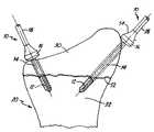
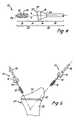
- FIG. 5is a side view of the second embodiment of the invention during implantation with a fractured bone.
- FIG. 6is a side view of the second embodiment of the invention after implantation.
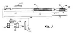
- FIG. 7is a side view assembly drawing of a third embodiment modified to permit reverse fixation.
- a preferred convertible threaded compression device or CTCD 10 of the present inventionincludes an anchor section 12 located distally of an intermediate fragment section 14 .
- a compression section 16is provided proximally of the intermediate fragment section 14
- a rotation section 18is provided proximally of the compression section 16 .
- the CTCD 10has many applications of connecting a fragment to an anchor substrate other than bone, the CTCD 10 has several features which make it particularly advantageous for orthopaedic applications, and the CTCD 10 will be generally described in its orthopaedic use.
- the anchor section 12 and the fragment section 14penetrate the bone 20 , while the compression section 16 and the rotation section 18 remain outside on the exterior of the bone 20 .
- the anchor section 12is shorter than the combined length of the bone exterior section 24 , i.e., the compression section 16 and the rotation section 18 . More preferably, the entire bone penetrating section 22 , i.e., the anchor section 12 and the fragment section 14 , are shorter in combined length than the combined length of the bone exterior section 24 , i.e., the compression section 16 and the rotation section 18 . Additionally, the preferred rotation section 18 makes up at least one third of the entire length of the CTCD 10 . More preferably, the rotation section 18 makes up 45% or more of the entire length of the CTCD 10 . Most preferred lengths for the anchor section 12 , the fragment section 14 , the compression section 16 and the rotation section 18 are provided below in Table I.
- the distal anchor section 12has a shaft portion 26 terminating in a drill tip 28 .
- the hole which is made in the fragment 30 and the anchor bone 32 for the CTCD 10is generally not pre-drilled, but rather is drilled by the drill tip 28 during advancement of the CTCD 10 through the fragment 30 and into the anchor bone 32 .
- the drill tip 28By using the drill tip 28 to drill the hole rather than pre-drilling, the duration of the insertion procedure is shortened, which is particularly important during surgical applications for minimizing both the trauma to the patient and the cost of the procedure.
- the holecan be pre-drilled in the fragment 30 and/or the anchor bone 32 , particularly for larger diameter CTCDs, but the pre-drilled hole is preferably the size of or smaller than the minor diameter of the distal anchor section 12 .
- the drill tip 28may be constructed in accordance with drill tip techniques used on current bone wires and bone screws, such as a three-sided sharp trocar. As known in the art, this drill tip 28 assists the CTCD 10 in drilling a hole through bone 20 , breaking up bone and removing bone powder and minute bone pieces from the hole during drilling.
- the shaft portion 26includes anchor threads 34 , which serve both to advance the CTCD 10 into the anchor bone 32 during rotation, and to anchor the CTCD 10 into the anchor bone 32 after implantation is completed.
- the shaft portion 26has a relatively short length suitable for anchoring in a desired anchor bone 32 .
- the shaft portion 26 of the distal anchor section 12may have a length in the range of about 5 to 10 mm for about a five to ten millimeter anchor.
- the CTCD 10is advanced through a fragment 30 and into an anchor bone 32 until the distal anchor section 12 is substantially entirely within the anchor bone 32 .
- the anchor threads 34are constructed with an appropriate width and pitch to suitably perform the advancing and anchoring functions in a CTCD 10 .
- the anchor threads 34have a minor diameter and a major diameter.
- the preferred anchor section 12has substantially cylindrical threads 34 .
- the anchor threads 34may be conical or otherwise increasing or changing in diameter as a function of axial location, but for purposes of this application, the “minor diameter” and “major diameter” of the anchor threads are selected at the axial location of their greatest value, for which most preferred dimensions are set forth below in Table 1.
- the anchor threads 34 in a preferred embodimenthave a pitch in the range of 0.5 to 1.0 mm per rotation.
- the anchor threads 34are preferably self-tapping on the distal side of the anchor section 12 , as commonly known in the screw thread art. Having the anchor threads 34 be self-tapping for insertion decreases the number of surgical steps and surgery time as compared to tapping with a separate tap, while providing a firmer attachment with less bone damage and requiring less drill force as compared to not tapping at all.
- the CTCD 10 of the present inventionis intended to be surgically implanted and left within the patient for a healing duration while the fragment 30 attaches and grows together to the anchor bone 32 .
- bone tissuemay grow back within the threads cut into the fragment 30 by the anchor threads 34 .
- the preferred threads 34are self-tapping on the proximal side as well. Having the threads 34 be self-tapping on the proximal side reduces the torque necessary for removal, decreasing the likelihood of shearing breakage of the CTCD 10 during removal and decreasing the likelihood of damage to the surrounding bone and surrounding tissue during removal.
- Having the threads 34 be self-tapping on the proximal sideis also quite important for reverse insertion, wherein the proximal side of the CTCD 10 enters the anchor bone 32 first and the CTCD 10 is then pulled back through the anchor bone 32 and bone fragment 30 .
- the preferred anchor threads 34have a thread form which is angled against pull-out.
- the angle of the thread formcan significantly increase the pull-out force which can be supported by the CTCD 10 , which can be very important especially if the anchor bone 32 is weak, damaged or overly porous.
- the fragment section 14has a diameter which is smaller than at least the major diameter of the anchor section 12 , and preferably no greater than the minor diameter of the anchor section 12 as well. Being smaller in diameter, the fragment section 14 does not interfere with the hole in the fragment 30 created by the anchor section 12 when the anchor section 12 was advanced through the fragment 30 .
- the fragment section 14may have smooth cylindrical profile, contrasted against the threaded anchor section 12 . Preferred diameters for the fragment section 14 are set forth below in Table I.
- the fragment section 14thus follows behind the minor diameter on the threaded anchor section 12 and does not substantially engage the bone of the fragment 30 .
- the CTCD 10 of the present inventioncan be thought of as having a reverse taper, with the proximal fragment section 14 of the CTCD 10 being narrower in diameter than the distal anchor section 12 .
- the reverse taperis particularly important for accurately imparting the proper compression force on the bone fragment 30 during healing.
- the CTCD 10may be cannulated.
- a cannulaassists in targeting the CTCD 10 by permitting the CTCD 10 to be placed over a targeting K-wire or bone pin.
- the length of the fragment section 14should approximately correspond with the length of the fragment 30 in the injured bone 20 . Obviously, the length of the fragment 30 depends upon the injury, and is not the same for all fractured bones.
- the CTCD 10may be provided as part of a kit which allows the surgeon to select the length of the fragment section 14 as desired for a particular fragment 30 .
- the kitmay include bone wires 10 with fragment section lengths which vary in 2 mm increments, i.e., lengths for the fragment section 14 of 2, 4, 6, 8, 10, 12, 14 and 16 mm.
- the length of the CTCD 10may be convertible by the surgeon as described below, and thus a single length of CRCD 10 may be used for a wide range of fractures, reducing inventory and cost required of the surgeon as well as eliminating any need for the surgeon to measure fragment length and eliminating any possibility that the surgeon could err in measurement or otherwise select the wrong length for the fragment section 14 .
- the compression section 16provides a compression engagement 36 which defines the proximal extent of the fragment section 14 .
- the purpose of the compression engagement 36is to place a compression force on an exterior surface of the bone fragment 30 , and thus externally bias the bone fragment 30 toward the anchor bone 32 .
- the compression engagement 36includes a shoulder 38 extending at a substantial angle to the wire axis for substantial contact with an exterior surface of the bone fragment 30 .
- the CTCD 10thus allows for compression via the compression engagement 36 after insertion through the skin and placement of the compression engagement 36 against the bone fragment 30 .
- the compression engagement 36is provided by one or more nuts 40 , 42 placed on a proximal threaded shaft section 44 .
- a preferred length for the proximal threaded shaft section 44is within the range of about 5 to 80 mm, such as about 15 mm.
- the preferred compression nut 40has a compression shoulder section 46 and a drive section 48 .
- the compression shoulder section 46is on the distal side of the nut 40 and has a cylindrical outer profile, such as an outer diameter of 4 mm, or with an outer diameter which is about 2 mm larger than the shaft diameter of the CTCD 10 .
- the compression shoulder section 46has an inside bore, which is large enough to fit over both the proximal threaded shaft section 44 and the fragment section 14 .
- the inside boremay be a smooth cylindrical hole of 1.85 mm diameter for use with a CTCD 10 having 1.5 mm shaft diameters.
- the length of the compression shoulder section 46may be designed as desired to correspond with the amount of adjustment and flexibility desired. If kits of bone wires 10 are provided with a 2 mm variance in length of fragment sections 14 , then the length of the compression shoulder section 46 may match this variance, i.e., extend axially for at least 2 mm.
- the threaded connection between the compression nut 40 and the proximal threaded shaft section 44provides infinite adjustability of the axial position of the compression nut 40 on the CTCD 10 . While other attachment methods may be alternatively used to provide axial adjustability of the compression shoulder section 46 relative to the CTCD 10 , a threaded attachment is a relatively low cost and reliable method to provide such adjustability.
- the drive section 48is on the proximal side of the compression nut 40 to enable the surgeon to rotationally advance the compression nut 40 with a standard tool.
- the drive section 48 of the compression nut 40may have a traditional hexagonal profile with a distance between opposing flats of about 3.45 mm.
- the drive section 48is internally threaded to mate with the external threads of the proximal threaded shaft section 44 , such as a threaded length of 4 mm.
- a lock nut 42may be further used to secure the compression nut 40 at a desired axial position, such as a lock nut 42 of 2 mm in length.
- the most preferred embodimentomits the lock nut 42 , reducing the steps required of the surgeon for proper fixation.
- the compression engagement 36is a tear-drop shoulder 50 .
- a tear drop shoulder 50could be placed on the proximal side of the compression nut 40 or lock nut 42 . More preferably and in contrast with the compression nut 40 , the tear-drop shoulder 50 is integrally formed or permanently affixed to the rest of the CTCD 10 .
- a distal shoulder surface 38is provided for contact with the exterior surface of the bone fragment 30 .
- the distal shoulder surface 38preferably has a curvature of large radius, for enhancing the likelihood of a smooth engagement with the exterior surface of the fragment 30 .
- the CTCD 10may be included as part of a kit with several different compression engagements 36 each having a different radius of curvature on the distal shoulder surface 38 , enabling the surgeon to pick the compression engagement 36 having a distal shoulder surface 38 which best matches the surface of the bone fragment 30 .
- the intentis to support the compression force with a broad surface to surface contact between the compression engagement 36 and the bone fragment 30 rather than at a point contact which could dig into and damage the bone fragment 30 .
- a washer 62(shown in FIG. 7 ) between the compression engagement 36 and the bone fragment.
- the washer 62can be selected at a size that changes the location and/or areal extent of the compression force place on the bone. If desired, the washer 62 can be selected to have a radius of curvature on its distal side to enable the surgeon to select the shape which best matches the surface of the bone fragment 30 .
- the washer 62can also be of a different material than the compression engagement 36 and the rest of the CTCD 10 , to provide additional compressibility, provide a controlled-release active agent to the wound site, etc. If desired, a collection of washers 62 may be provided to the surgeon in a kit to permit the surgeon to select the best washer 62 for the particular fracture being treated.
- the compression shoulder 38provides substantially all of the force pressing the bone fragment 30 into the anchor bone 32 during the healing duration.
- the present inventionpermits control of this compression force in either of two ways.
- the compression forcecan be selected by the surgeon by determining how far to rotationally advance the CTCD 10 into the anchor bone 32 , while the compression shoulder 38 remains at a constant longitudinal position relative to the CTCD 10 .
- supplying a compression force in this mannermay require the surgeon to positively rotate the compression nut 40 during rotation of the CTCD 10 .
- the tear-drop shoulder 50is integrally formed or permanently secured to the CTCD 10 , so the surgeon need not take any further steps other than rotating the CTCD 10 , and the compression shoulder 38 will always advance with the rotating CTCD 10 .
- the compression forcecan be selected by the surgeon after the CTCD 10 is fully advanced into the anchor bone 32 , by rotationally advancing the compression nut 40 relative to a stationary CTCD 10 .
- Thisallows the surgeon to customize the CTCD 10 as to the length between the tip 28 of the CTCD 10 and the compression shoulder 38 .
- supplying a compression force in this mannermay require the surgeon to positively hold the CTCD 10 in a non-rotating position during rotation of the compression nut 40 .
- the surgeoncan monitor the amount of compression force being applied in any of several different ways.
- the surgeonmay be able to visually (either directly or with the aid of scoping equipment) see advancement of the fragment 30 toward the anchor bone 32 .
- FIG. 5shows the fragment 30 separated from the anchor bone 32 by a slight gap 52
- FIG. 6shows the fragment 30 having been moved against the anchor bone 32 to completely close the gap 52 .
- the surgeonmay have the sensitivity to feel the change in torque associated with advancing the compression shoulder 38 against the fragment 30 , either by hand or with the aid of a monitoring tool such as a torque wrench. Such “feel” of the advancing torque requirements is relatively easy with the embodiments of FIGS.
- the amount of torque applied in advancing the compression shoulder 38can be controlled below a maximum threshold value. Either a drill having a controlled or set maximum torque can be used, or the rotational engagement structure (for instance, the flats of the compression nut 40 ) can be designed to shear off at a desired torque. In practice, all three methods may be used simultaneously.
- FIGS. 1-3 and 7can provide a further benefit, provided that a proximal threaded shaft section 44 which supports the compression nut 40 is made long enough and of small enough diameter. Namely, the proximal threaded shaft section 44 can be substantially longer than the desired amount of compression movement. Provided the proximal threaded shaft section 44 will fit within the overbore of the fragment 30 created by the anchor section 12 , the CTCD 10 may be advanced until a substantial portion of the proximal threaded shaft section 44 resides within the fragment 30 . The selectable length of the fragment section 14 is then not as critical. For instance, a preferred length for the proximal threaded shaft section 44 in the embodiment of FIGS.
- the preferred compression nut 40 together with the lock nut 42have an axial length of only 8 mm.
- the diameter of the proximal threaded shaft section 44permits it to fit within the overbore drilled by the anchor section 12 , then up to 7 mm of the proximal threaded shaft section 44 can be placed within the overbore in the fragment 30 .
- the compression nut 40can be advanced until at least the compression shoulder section 46 extends over the fragment section 14 , i.e., axially for 2 mm beyond the end of the proximal threaded shaft section 44 , for a total range of compression motion for the compression shoulder 38 of 9 mm.
- the kitneed only include fragment sections 14 with a length variance of the total range of compression motion, e.g, a kit with fragment sections 14 of 2, 11 and 20 mm would allow use on a fragment 30 of anywhere from 0 to 27 mm in thickness. If the length of the proximal threaded shaft section 44 was lengthened to 33 mm, then a single CTCD 10 with a fragment section 14 of 2 mm could be used on fragments 30 of 0 to 27 mm in thickness.
- the tradeoff for this flexibility in lengthlies in the strength of the CTCD 10 .
- the major diameter of the proximal threaded shaft section 44should be 1.5 mm or less to fit within the overbore in the fragment 30 to the same extent as the fragment section 14 fits within the overbore. If the thread depth is retained at at least 0.15 mm, and major diameter of 1.5 mm results in a minor diameter of no greater than 1.2 mm. However, the minor diameter must be strong enough to support the required torque to drive the anchor section 12 through the fragment 30 and through the anchor bone 32 . With current materials, a minor diameter of 1.2 mm over a 33 mm length results in a brittle, weak product, which is likely to break off during driving through the bone 20 or during use.
- the preferred embodiments of the CTCD 10retain a minimum diameter of at least 1.5 mm throughout.
- the major diameter of the proximal threaded shaft section 44is accordingly selected at 1.83 mm. This major diameter interferes with the minor diameter of 1.65 mm drilled by the “thin” anchor section 12 , and hence the CTCD 10 should be used without advancing any part of the proximal threaded shaft section 44 into the fragment bore.
- the compression nut 40only has 2 mm of axial advancement flexibility, and the CTCDs 10 are thus provided in kits of 2 mm variance in length of fragment sections 14 .
- the major diameter for the proximal threaded shaft section 44 of 1.83 mmdoes not interfere with the minor diameter of 1.85 mm drilled by the “thick” anchor section 12 .
- the proximal threaded shaft section 44can extend into the fragment bore drilled by the “thick” anchor section 12 , and the compression nut 40 in the preferred “thick” embodiment has a full 9 mm of axial advancement flexibility.
- the proximal threaded shaft section 44extend fully up to the anchor section 12 , and having little or no length of fragment section 14 .
- the smooth surface of the fragment section 14prevents bone ingrowth and makes the CTCD 10 more easily removed than simply having the entire length threaded.
- Workers skilled in the artwill appreciate that there is no medical purpose achieved by fully threading the fragment section 14 , because every bone fragment has some thickness.
- the preferred embodimentsall have a fragment section length of at least 2 mm. For purposes of this invention, if the CTCD 10 is threaded fully up to the anchor section 12 , the distal 2 mm of the machine thread form should be considered to be the fragment section 14 .
- the flexibility of compression movement provided by having the proximal threaded shaft section 44 fit within the overbore created by the anchor section 12needs should be understood within the context of the material with which the CTCD 10 is being used.
- the proximal threaded shaft section 44may fit within the overbore created by the anchor section 12 merely by having the major diameter of the proximal threaded shaft section 44 be less than the major diameter of the anchor section 12 (CSOD ⁇ AOD).
- the major diameter of the proximal threaded shaft section 44is greater than the minor diameter of the anchor section 12 , (i.e., CSOD>AID) such that there is some interference between the internal threads cut into the bone by the anchor section 12 and the threads of the proximal threaded shaft section 44 ), the bone fragment/proximal threaded shaft section interference may be sufficiently small due to the weakened nature of the bone that it can be overcome by the compression force.
- the minor diameter of the proximal threaded shaft section 44is also less than the minor diameter of the anchor section 12 (i.e., CSID ⁇ AID).
- the rotation section 18 of the CTCD 10extends substantially beyond the end of the compression section 16 . In many uses, the rotation section 18 will extend outside the patient's skin during the entire healing duration, which can greatly facilitate bone healing.
- the rotation section 18allows the CTCD 10 to be used in fixating the fracture with a fixator support structure as described in U.S. Pat. Nos. 6,058,748, 6,283,946, 6,652,524 and U.S. patent application Ser. Nos. 10/233,897 and 10/699,213, incorporated by reference, which can allow the proper amount of stress to be placed on the bone 20 during healing, substantially benefitting the healing process.
- the fixator support structureattaches to the rotation section 18 of the CTCD 10 .
- the placement of the compression shoulder 38 against the fragment 30also increases the fixation by reducing wire toggle, such as may occur during wrist motion.
- the rotation section 18allows the CTCD 10 to be rotated without interference with tissue adjacent the bone 20 , so the surrounding tissue is less damaged during surgery than occurred with prior art methods.
- the rotation section 18is cylindrical with a diameter of 1.5 mm, and extends for 100 to 150 mm.
- the length of the rotation section 18 relative to the length of the entire CTCD 10is a significant variable to ensure that the rotation section 18 can be used for its desired purpose, as is the length of the bone exterior section 24 relative to the length of the entire CTCD 10 .
- Table IIexpresses the ratios of length of rotation section 18 and length of the bone exterior section 24 relative to the length of the entire CTCD 10 for the preferred embodiments.
- the rotation section 18in each case makes up more than a third of the total length of the CTCD 10 , and more preferably 40% or more of the total length of the CTCD 10 .
- These length ratiosensure that a sufficient length of rotation section 18 is provided that the CTCD 10 can be percutaneously manipulated without substantial interference from the patient's tissue. Workers skilled in the art will appreciate that the same rotation section length ratios could be effectively achieved even if the entire length of the rotation section 18 was threaded identically with the compression section 16 .
- the bone exterior section 24in each case makes up more than a third of the total length of the CTCD 10 , and more preferably more than half of the total length of the CTCD 10 , and even more preferably more than 75% of the total length of the CTCD 10 .
- the present inventionincludes several features which are specifically directed to removal of the CTCD 10 after the healing duration.
- the CTCD 10 of the present inventionleaves a significant length exposed through the skin to grasp for removal without damaging tissue.
- the threads of the proximal threaded shaft section 44have a different pitch and a different shape than the anchor threads 34 .
- the proximal threaded shaft section 44may have a pitch of 0.4 mm per revolution, as compared to the preferred anchor thread pitch of 0.5 to 1.0 mm. Counterclockwise rotation of the CTCD 10 will cause the CTCD 10 to retract its anchor thread pitch, i.e., 0.5 to 1.0 mm per revolution.
- the nut(s) 40 , 42must retract with counterclockwise rotation of the CTCD 10 . That is, the nut(s) 40 , 42 could rotate with the rotating CTCD 10 , in which case the nut(s) 40 , 42 would retract at the anchor thread pitch, i.e., 0.5 to 1.0 mm per revolution.
- the nut(s) 40 , 42will still back out at the difference between pitches, i.e., 0.1 mm to 0.6 mm per revolution of the CTCD 10 .
- the compression nut 40rotates all of the way to the distal end of the proximal threaded shaft section 44 , the compression nut screw thread has a smaller inside diameter than the outside diameter of the fragment section 14 (at least at a proximal side of the fragment section 14 ), preventing the compression nut 40 from further advancing onto the fragment section 14 .
- the proximal threaded shaft section 44may have a thread form which is balanced in both proximal and distal directions, in contrast to the preferred anchor threads 34 which have a thread form which is angled against pull-out.
- the thread form for the proximal threaded shaft section 44may be angled oppositely to the thread form of the preferred anchor threads 34 , to better support the compression force placed on the compression nut 40 .
- the proximal surface 54 of the tear-drop shoulder 50assists in removal of the CTCD 10 through tissue which may grown around the bone exterior section 24 of the CTCD 10 during the healing duration.
- the proximal surface 54 of the tear-drop shapeis sloped for removal, with the slope angle being shallow near the axis of the CTCD 10 , becoming steeper at intermediate diameters, and then again becoming shallow near the maximum diameter of the tear-drop shoulder 50 . This shape helps to separate the overlying tissue with minimal damage to such surrounding tissue when the CTCD 10 is removed.
- the proximal surface of the compression nut 40 and/or the lock nut 42could alternatively be modified to provide a similar slope for assisting in separating overlying tissue during removal.
- CTCD 10 of the present inventionBecause of the various features of the CTCD 10 of the present invention which facilitate removal, removal of the CTCD 10 can be accomplished without requiring a separate incision to be made after the healing duration. Avoiding this additional incision greatly helps in healing the tissue over the fractured bone 20 , both in terms of the length of time required for full healing and in terms of avoiding the build-up of scar tissue.
- the CTCD 10is designed to permit forward fixation to the bone. In some embodiments, only forward fixation may be used, and the proximal end of the rotation section 18 may be squared off. Alternatively as shown in FIG. 7 , the CTCD 10 may be designed for reverse fixation, useful in such cases as correcting digit or extremity (e.g., toe) deformity. For reverse fixation, a pointed trocar tip 56 is provided on the proximal end of the rotation section 18 .
- the CTCD 10may be formed out of any surgically acceptable strong material, such as surgical acceptable stainless steel (such as 316 LVM, per ASTM F1350 or ASTM F138, electropolished and passivated) or a titanium alloy (such as TI-6AL-4V, per ASTM F136).
- surgical acceptable stainless steelsuch as 316 LVM, per ASTM F1350 or ASTM F138, electropolished and passivated
- titanium alloysuch as TI-6AL-4V, per ASTM F136.
- the CTCD 10might also be formed out of a bioresorpable material if a sufficiently strong bioresorbable material is selected, or if holes in the bone are pre-drilled and/or pre-tapped.
- CTCD 10 of the present inventionto repair a fractured bone
- Insertion of the CTCD 10is performed through a small incision with blunt dissection carried to the bone 20 .
- the CTCD 10is drilled through the fragment 30 , and the thicker diameter anchor threads 34 overbore a hole through the fragment 30 . Drilling through a sheath (not shown) helps protect surrounding tissue so that the threads 34 do not damage nearby soft tissue.
- the surgeonmay optionally use the CTCD 10 to manipulate the fragment 30 .
- the bone exterior section 24extends significantly beyond the patient's tissue.
- the surgeonmay grasp the bone exterior section 24 in a “joystick” fashion to reposition or bias the bone fragment 30 relative to the anchor bone 32 .
- This “joysticking” method of manipulating the bone fragment 30is particularly appropriate for larger diameter CTCDs 10 , which can support significant forces and moments applied to the bone fragment 30 without bending or breaking.
- the surgeonfurther screws the CTCD 10 such that the bone anchor section 12 advances into the anchor bone 32 with the fragment section 14 in the bone fragment 30 .
- the surgeoncan hold the bone exterior section 24 in a desired alignment while screwing into the anchor bone 32 .
- the thicker diameter anchor threads 34then reach the anchor bone 32 and pull the CTCD 10 axially forward. Once the narrower fragment section 14 of the CTCD 10 extends through the fragment 30 , the CTCD 10 is no longer in threaded engagement with the fragment 30 .
- the CTCD 10is preferably advanced until the anchor section 12 is fully within the anchor bone 32 . This places the fragment section 14 sufficiently forward that the fragment section 14 extends through the bone fragment 30 without threaded engagement with the bone fragment 30 .
- the CTCD shown in FIG. 7can be used for forward fixation with the procedure described for FIGS. 1-3 , or can be used for reverse fixation, in which case a modified procedure is used.
- the CTCD 10is introduced proximal end 56 first to the back side of the anchor bone 32 , and back driven through the anchor bone 32 in the direction shown by arrow 58 in FIG. 7 .
- the proximal end 56 of the CTCD 10is driven through the anchor bone 32 until the proximal end 56 of the CTCD 10 extends out of the fragment 30 .
- a drillcan be secured to the rotation section 18 of the CTCD 10 and driven in reverse direction and pulled back (in the direction shown by arrow 58 ) until the anchor threads 34 reverse cut through the anchor bone 32 .
- anchor threads 34preferably self-tapping on the proximal side of the anchor section 12
- the compression threads 44may also be self-tapping on the proximal side of the compression section 16 to assist in pulling through the anchor bone.
- the compression engagement 36In its fully advanced and final position, the compression engagement 36 is in substantial contact with an exterior surface of the bone fragment 30 to bias the bone fragment 30 toward the anchor bone 32 .
- the compression nut 40can be tightened with a wrench until the compression shoulder 38 engages the exterior surface of the fragment 30 .
- the surgeonmay advance the CTCD 10 by screwing the CTCD 10 forward until the anchor section 12 is fully seated in its final position within the anchor bone 32 , and then, with the CTCD 10 stationary, screw or otherwise move the compression engagement 36 axially on the elongated shaft to position the compression engagement 36 in an axial position to make contact with an exterior surface of the bone fragment 30 with the desired compression force.
- the surgeonmay select the desired axial placement of the compression nut 40 on the CTCD 10 and position the nut 40 in that position, and then advance the compression engagement 36 to the substantial contact position as part of advancing the anchor section 12 within the anchor bone 32 .
- the compression engagement 36is integrally attached on the CTCD 10 such as in the case of the preferred tear-drop shoulder 50 , then the compression engagement 36 is advanced to this substantial contact position merely by advancing the anchor section 12 within the anchor bone 32 .
- the CTCD 10may be used to axially move the fragment 30 toward the anchor bone 32 to reduce or eliminate the gap 52 prior to achieving the desired compression force
- the bone exterior section 24may be cut, sheared off or otherwise shortened proximal to the compression engagement 40 , 50 .
- Such a cutting or shearing actcan shorten the CTCD 10 so it no longer resides outside the patient's tissue during the healing duration. Shortening of the CTCD 10 after complete advancement into the anchor bone 32 is particularly appropriate for healing modalities wherein the primary purpose of the CTCD 10 was to enable “joysticking” of the bone fragment 30 , without any desired attachment of an external fixator.
- the clipping stepeffectively converts the CTCD 10 from a variable length device to a fixed length device.
- the compression nut 40cannot advance axially on the CTCD 10 because it is in tight contact with the bone.
- the compression nut 40cannot retract axially on the CTCD 10 because the deformed thread form at the cut prevents further rotation of the compression nut 40 .
- the CTCD 10is converted into a fixed length lag bolt at the exact length selected in situ within the fracture by the surgeon.
- the bone exterior section 24may include a section of reduced thickness (not shown) to facilitate the shortening act.
- the section of reduced thicknesscan be designed to withstand a set torque before shearing off, such that the surgeon drives the CTCD 10 forward into the anchor bone 32 until the compression engagement 36 resists further screwing with sufficient torque to shear off the proximal side of the bone exterior section 24 at the section of reduced thickness.
- pre-selecting the location of cuttingwill prevent the surgeon from selecting the exact length in situ as described above.
- the CTCD 10should include structure which will not be cut off which can transmit removal torque.
- the flats on compression nut 40may allow the surgeon to apply torque for removal of the CTCD 10 after the healing duration, and even after the major length of the bone exterior section 24 of the CTCD 10 has been cut off.
- the CTCD 10is simply removed from the bone 20 by counterclockwise rotation of the CTCD 10 , perhaps by applying reverse torque on the rotation section 18 .
- the sloped profileassist in separating tissue, causing as little additional tissue damage as possible.
- the present inventioncan be used on most types of fractures which have previously been treated by percutaneous pinning. Avulsion fractures of the hand and foot as well reconstruction procedures such as IP fusions and hammertoe correction are excellent applications.
- the joysticking treatment methodcan be applied to a wide variety of fractures, making the CTCD 10 easier to implant into a fracture than traditional bone screws.
- the CTCD 10has many fastener applications outside the orthopaedic arts, particularly when access to and/or movement of the fragment relative to the anchor substrate is limited, and also when predrilling is not advisable and/or possible.
- an excellent application of the CTCD 10would be to repair wood which is in the process of splitting, such as in furniture or cabinetry.
Landscapes
- Health & Medical Sciences (AREA)
- Orthopedic Medicine & Surgery (AREA)
- Surgery (AREA)
- Life Sciences & Earth Sciences (AREA)
- Heart & Thoracic Surgery (AREA)
- Nuclear Medicine, Radiotherapy & Molecular Imaging (AREA)
- Engineering & Computer Science (AREA)
- Biomedical Technology (AREA)
- Neurology (AREA)
- Medical Informatics (AREA)
- Molecular Biology (AREA)
- Animal Behavior & Ethology (AREA)
- General Health & Medical Sciences (AREA)
- Public Health (AREA)
- Veterinary Medicine (AREA)
- Surgical Instruments (AREA)
Abstract
Description
| TABLE I |
| PREFERRED EMBODIMENT DIMENSIONS |
| RSSD | RSL | CSOD | CSID | CSL | FSSD | FSL | AOD | AID | ATL | TTL |
| 1.5 | 136 | 1.8 | 1.6 | 15 | 1.5 | 5.5 | 2.5 | 1.8 | 2.5 | 1.5 |
| 1.5 | 126 | 1.8 | 1.6 | 15 | 1.5 | 10 | 2.5 | 1.8 | 8.4 | 2 |
| 1.5 | 91 | 1.8 | 1.6 | 40 | 1.5 | 20 | 2.5 | 1.8 | 8.4 | 2 |
| 1.5 | 119 | 1.8 | 1.6 | 40 | 1.5 | 20 | 2.5 | 1.8 | 8.4 | 2 |
| 1.9 | 118 | 2.3 | 2.0 | 40 | 1.9 | 20 | 3.2 | 2.3 | 8.5 | 2 |
| 1.9 | 78 | 2.3 | 2.0 | 80 | 1.9 | 20 | 3.2 | 2.3 | 8.5 | 2 |
| 2.1 | 118 | 2.6 | 2.2 | 40 | 2.1 | 20 | 3.5 | 2.6 | 9 | 2.5 |
| 2.1 | 78 | 2.6 | 2.2 | 80 | 2.1 | 20 | 3.5 | 2.6 | 9 | 2.5 |
| 2.4 | 117 | 2.9 | 2.5 | 40 | 2.4 | 20 | 4 | 2.9 | 9.5 | 2.5 |
| 2.4 | 77 | 2.9 | 2.5 | 80 | 2.4 | 20 | 4 | 2.9 | 9.5 | 2.5 |
| 2.5 | 116 | 3.1 | 2.7 | 40 | 2.5 | 20 | 4.2 | 3.1 | 10 | 3 |
| 2.5 | 76 | 3.1 | 2.7 | 80 | 2.5 | 20 | 4.2 | 3.1 | 10 | 3 |
| 2.7 | 116 | 3.3 | 2.9 | 40 | 2.7 | 20 | 4.5 | 3.3 | 10 | 3 |
| 2.7 | 76 | 3.3 | 2.9 | 80 | 2.7 | 20 | 4.5 | 3.3 | 10 | 3 |
| RSSD: Rotational Section Shaft Diameter | ||||||||||
| RSL: Rotational Section Length | ||||||||||
| CSOD: Compression Section Major Diameter | ||||||||||
| CSID: Compression Section Minor Diameter | ||||||||||
| CSL: Compression Section Length | ||||||||||
| FSSD: Fragment Section Shaft Diameter | ||||||||||
| FSL: Fragment Section Length | ||||||||||
| AOD: Anchor Major Diameter | ||||||||||
| AID: Anchor Minor Diameter | ||||||||||
| ATL: Anchor Thread Length | ||||||||||
| TTL: Trocar Tip Length | ||||||||||
| Dimensions are given in mm to two significant digits. | ||||||||||
| TABLE II |
| Rotation and Bone Exterior Section Length Ratios |
| RSSD | RSL | BESL | Total | RSLR | BESLR | ||
| 1.5 | 136 | 151 | 161 | 84% | 94% | ||
| 1.5 | 126 | 141 | 161 | 78% | 88% | ||
| 1.5 | 91 | 131 | 161 | 57% | 81% | ||
| 1.5 | 119 | 159 | 189 | 63% | 84% | ||
| 1.9 | 118 | 158 | 189 | 62% | 84% | ||
| 1.9 | 78 | 158 | 189 | 41% | 84% | ||
| 2.1 | 118 | 158 | 189 | 62% | 84% | ||
| 2.1 | 78 | 158 | 189 | 41% | 84% | ||
| 2.4 | 117 | 157 | 189 | 62% | 83% | ||
| 2.4 | 77 | 157 | 189 | 41% | 83% | ||
| 2.5 | 116 | 156 | 189 | 61% | 83% | ||
| 2.5 | 76 | 156 | 189 | 40% | 83% | ||
| 2.7 | 116 | 156 | 189 | 61% | 83% | ||
| 2.7 | 76 | 156 | 189 | 40% | 83% | ||
| RSSD: Rotational Section Shaft Diameter | |||||||
| RSL: Rotational Section Length | |||||||
| BESL: Bone Exterior Section Length | |||||||
| Total: Total Length of CTCD | |||||||
| RSLR: Rotational Section Length Ratio as percentage of Total Length | |||||||
| BESLR: Bone Exterior Section Length Ratio as percentage of Total Length | |||||||
Claims (1)
Priority Applications (1)
| Application Number | Priority Date | Filing Date | Title |
|---|---|---|---|
| US10/790,342US7517350B2 (en) | 2002-11-20 | 2004-03-01 | Convertible threaded compression device and method of use |
Applications Claiming Priority (3)
| Application Number | Priority Date | Filing Date | Title |
|---|---|---|---|
| US10/300,078US7641677B2 (en) | 2002-11-20 | 2002-11-20 | Compression bone fragment wire |
| US50356503P | 2003-09-17 | 2003-09-17 | |
| US10/790,342US7517350B2 (en) | 2002-11-20 | 2004-03-01 | Convertible threaded compression device and method of use |
Related Parent Applications (1)
| Application Number | Title | Priority Date | Filing Date |
|---|---|---|---|
| US10/300,078Continuation-In-PartUS7641677B2 (en) | 2002-11-20 | 2002-11-20 | Compression bone fragment wire |
Publications (2)
| Publication Number | Publication Date |
|---|---|
| US20040167519A1 US20040167519A1 (en) | 2004-08-26 |
| US7517350B2true US7517350B2 (en) | 2009-04-14 |
Family
ID=32871562
Family Applications (1)
| Application Number | Title | Priority Date | Filing Date |
|---|---|---|---|
| US10/790,342Expired - LifetimeUS7517350B2 (en) | 2002-11-20 | 2004-03-01 | Convertible threaded compression device and method of use |
Country Status (1)
| Country | Link |
|---|---|
| US (1) | US7517350B2 (en) |
Cited By (24)
| Publication number | Priority date | Publication date | Assignee | Title |
|---|---|---|---|---|
| US20130238036A1 (en)* | 2010-11-30 | 2013-09-12 | Genossis Llc | Bone Compression and Fixation Devices |
| US8764842B2 (en) | 2012-05-31 | 2014-07-01 | Michael Graham | Interphalangeal joint implant methods and apparatus |
| US8906075B2 (en) | 2010-07-14 | 2014-12-09 | DePuy Synthes Products, LLC | Methods and assemblies for aligning a bone fixation plate |
| CN104367378A (en)* | 2014-11-28 | 2015-02-25 | 王加利 | Minitype sleeve kirschner wire fixing device used for fixing fracture of metacarpal bone |
| US9027819B2 (en) | 2009-06-04 | 2015-05-12 | Rotation Medical, Inc. | Methods and apparatus having bowstring-like staple delivery to a target tissue |
| US9095444B2 (en) | 2009-07-24 | 2015-08-04 | Warsaw Orthopedic, Inc. | Implant with an interference fit fastener |
| RU2574114C2 (en)* | 2013-06-18 | 2016-02-10 | Валентин Георгиевич Виноградов | Tension rod for fixation of posterior structures of pelvic ring |
| US10231768B2 (en) | 2003-05-30 | 2019-03-19 | DePuy Synthes Products, Inc. | Methods for implanting bone plates |
| US10335211B2 (en) | 2004-01-26 | 2019-07-02 | DePuy Synthes Products, Inc. | Highly-versatile variable-angle bone plate system |
| US10342586B2 (en) | 2003-08-26 | 2019-07-09 | DePuy Synthes Products, Inc. | Bone plate |
| US10588679B2 (en) | 2014-11-01 | 2020-03-17 | Numagenesis, Llc | Compression fixation system |
| US10624686B2 (en) | 2016-09-08 | 2020-04-21 | DePuy Synthes Products, Inc. | Variable angel bone plate |
| US10772665B2 (en) | 2018-03-29 | 2020-09-15 | DePuy Synthes Products, Inc. | Locking structures for affixing bone anchors to a bone plate, and related systems and methods |
| US10820930B2 (en) | 2016-09-08 | 2020-11-03 | DePuy Synthes Products, Inc. | Variable angle bone plate |
| US10905476B2 (en) | 2016-09-08 | 2021-02-02 | DePuy Synthes Products, Inc. | Variable angle bone plate |
| US10925651B2 (en) | 2018-12-21 | 2021-02-23 | DePuy Synthes Products, Inc. | Implant having locking holes with collection cavity for shavings |
| US11013541B2 (en) | 2018-04-30 | 2021-05-25 | DePuy Synthes Products, Inc. | Threaded locking structures for affixing bone anchors to a bone plate, and related systems and methods |
| US11026727B2 (en) | 2018-03-20 | 2021-06-08 | DePuy Synthes Products, Inc. | Bone plate with form-fitting variable-angle locking hole |
| US11096732B2 (en)* | 2019-02-21 | 2021-08-24 | Glw, Inc. | Hybrid bone fixation wire |
| US11259851B2 (en) | 2003-08-26 | 2022-03-01 | DePuy Synthes Products, Inc. | Bone plate |
| US11291487B2 (en)* | 2018-12-21 | 2022-04-05 | Azurmeds Inc. | Screw fixation device, fixation kit and fixation method |
| US11291484B2 (en) | 2004-01-26 | 2022-04-05 | DePuy Synthes Products, Inc. | Highly-versatile variable-angle bone plate system |
| US11478289B2 (en) | 2018-05-04 | 2022-10-25 | Numagenesis, Llc | Compression fixation system |
| US12226135B1 (en) | 2024-02-13 | 2025-02-18 | Surgeon Design Center LLC. | Surgical guide wire engagement device |
Families Citing this family (36)
| Publication number | Priority date | Publication date | Assignee | Title |
|---|---|---|---|---|
| US7686811B2 (en)* | 2006-04-17 | 2010-03-30 | Zimmer Technology, Inc. | Surgical component fixation and method |
| US7981116B2 (en)* | 2007-05-25 | 2011-07-19 | Custom Spine, Inc. | Radiolucent screwdriver for orthopedic surgery |
| WO2010081029A1 (en) | 2009-01-08 | 2010-07-15 | Rotation Medical, Inc. | Implantable tendon protection systems and related kits and methods |
| US9179910B2 (en) | 2009-03-20 | 2015-11-10 | Rotation Medical, Inc. | Medical device delivery system and method |
| CA2763937C (en) | 2009-06-04 | 2017-05-23 | Rotation Medical, Inc. | Methods and apparatus for deploying sheet-like materials |
| US9198750B2 (en) | 2010-03-11 | 2015-12-01 | Rotation Medical, Inc. | Tendon repair implant and method of arthroscopic implantation |
| US9060789B2 (en)* | 2011-02-10 | 2015-06-23 | Robert B. Weinstein | Method and apparatus for preparing and fusion of small joints |
| US10952783B2 (en) | 2011-12-29 | 2021-03-23 | Rotation Medical, Inc. | Guidewire having a distal fixation member for delivering and positioning sheet-like materials in surgery |
| WO2012145059A1 (en) | 2011-02-15 | 2012-10-26 | Rotation Medical, Inc. | Methods and apparatus for fixing sheet-like materials to a target tissue |
| WO2012112565A2 (en) | 2011-02-15 | 2012-08-23 | Rotation Medical, Inc. | Methods and apparatus for delivering and positioning sheet-like materials |
| US9107661B2 (en) | 2011-12-19 | 2015-08-18 | Rotation Medical, Inc. | Fasteners and fastener delivery devices for affixing sheet-like materials to bone or tissue |
| EP2793712B1 (en) | 2011-12-19 | 2018-03-28 | Rotation Medical, Inc. | Fasteners for affixing sheet -like materials to bone or tissue |
| AU2012355433B2 (en) | 2011-12-19 | 2016-10-20 | Rotation Medical, Inc. | Apparatus and method for forming pilot holes in bone and delivering fasteners therein for retaining an implant |
| US9271726B2 (en) | 2011-12-19 | 2016-03-01 | Rotation Medical, Inc. | Fasteners and fastener delivery devices for affixing sheet-like materials to bone or tissue |
| WO2013101641A2 (en) | 2011-12-29 | 2013-07-04 | Rotation Medical, Inc. | Anatomical location markers and methods of use in positioning sheet-like materials during surgery |
| EP2797532B1 (en) | 2011-12-29 | 2016-04-06 | Rotation Medical, Inc. | Apparatus for delivering and positioning sheet-like materials in surgery |
| JP6495168B2 (en)* | 2012-07-25 | 2019-04-03 | オーソフィックス ソチエタ ア レスポンサビリタ リミタータ | Elongated pin for external modular fixation system for temporary and / or permanent fixation applications, and external modular fixation system |
| US10631994B2 (en) | 2012-10-12 | 2020-04-28 | Smith & Nephew, Inc. | Fusion Implant |
| US9770278B2 (en)* | 2014-01-17 | 2017-09-26 | Arthrex, Inc. | Dual tip guide wire |
| CA2945821C (en) | 2014-05-09 | 2018-09-04 | Rotation Medical, Inc. | Medical implant delivery system for sheet-like implant |
| US10064670B2 (en)* | 2014-05-12 | 2018-09-04 | DePuy Synthes Products, Inc. | Sacral fixation system |
| CA2949060A1 (en)* | 2014-05-12 | 2015-11-19 | DePuy Synthes Products, Inc. | Sacral fixation system |
| US10123796B2 (en) | 2014-11-04 | 2018-11-13 | Rotation Medical, Inc. | Medical implant delivery system and related methods |
| AU2015343273B2 (en) | 2014-11-04 | 2017-12-14 | Rotation Medical, Inc. | Medical implant delivery system and related methods |
| EP3215025B1 (en) | 2014-11-04 | 2020-12-23 | Rotation Medical, Inc. | Medical implant delivery system |
| CA2983341A1 (en) | 2015-05-06 | 2016-11-10 | Rotation Medical, Inc. | Medical implant delivery system and related methods |
| US10265156B2 (en) | 2015-06-15 | 2019-04-23 | Rotation Medical, Inc | Tendon repair implant and method of implantation |
| US10485595B2 (en) | 2015-07-13 | 2019-11-26 | IntraFuse, LLC | Flexible bone screw |
| US10499960B2 (en) | 2015-07-13 | 2019-12-10 | IntraFuse, LLC | Method of bone fixation |
| US10492838B2 (en) | 2015-07-13 | 2019-12-03 | IntraFuse, LLC | Flexible bone implant |
| US10154863B2 (en) | 2015-07-13 | 2018-12-18 | IntraFuse, LLC | Flexible bone screw |
| EP3397175B1 (en) | 2015-12-31 | 2021-11-24 | Rotation Medical, Inc. | Fastener delivery system |
| AU2016381936B2 (en) | 2015-12-31 | 2019-02-28 | Rotation Medical, Inc. | Medical implant delivery system and related methods |
| KR101672376B1 (en)* | 2016-03-08 | 2016-11-03 | 주식회사 에이알씨코리아 | Length adjustable osteosynthesis wire for bone fracture |
| WO2019113292A1 (en) | 2017-12-07 | 2019-06-13 | Rotation Medical, Inc. | Medical implant delivery system and related methods |
| WO2019168663A1 (en)* | 2018-03-02 | 2019-09-06 | Scot Hodkiewicz | Pin fastener with removeable drill bit for bone fixator |
Citations (52)
| Publication number | Priority date | Publication date | Assignee | Title |
|---|---|---|---|---|
| US2393694A (en) | 1945-04-10 | 1946-01-29 | Otto S Kirschner | Surgical apparatus |
| US2760488A (en)* | 1955-04-20 | 1956-08-28 | Robert B Pierce | Internal bone fixation apparatus |
| US4175555A (en) | 1977-02-24 | 1979-11-27 | Interfix Limited | Bone screw |
| US4450835A (en)* | 1981-02-20 | 1984-05-29 | Howmedica, Inc. | Method and system for inserting a surgical wire |
| US4456005A (en)* | 1982-09-30 | 1984-06-26 | Lichty Terry K | External compression bone fixation device |
| US4463753A (en) | 1980-01-04 | 1984-08-07 | Gustilo Ramon B | Compression bone screw |
| US4616638A (en)* | 1982-01-18 | 1986-10-14 | Richards Medical Company | Compression screw assembly |
| US4628921A (en) | 1983-10-03 | 1986-12-16 | Mauricio Rousso | Unilateral external fixation system for small bones |
| US4723541A (en) | 1986-05-19 | 1988-02-09 | Reese Hewitt W | Bone screw and method |
| US4854311A (en) | 1986-01-09 | 1989-08-08 | Acro Med Corporation | Bone screw |
| US4858601A (en) | 1988-05-27 | 1989-08-22 | Glisson Richard R | Adjustable compression bone screw |
| USRE33348E (en) | 1985-11-07 | 1990-09-25 | Zimmer, Inc. | Bone screw |
| US4964403A (en) | 1986-12-19 | 1990-10-23 | Huta Baildon Przedsiebiorstwo Panstwowe Katowice | Stabilizer for the treatment of the fracture of the neck and upper metaphysis of the femur |
| US5019079A (en) | 1989-11-20 | 1991-05-28 | Zimmer, Inc. | Bone screw |
| WO1992004875A1 (en) | 1990-09-24 | 1992-04-02 | David Mark Allison | Bone fixing device |
| US5122133A (en)* | 1990-10-26 | 1992-06-16 | Smith & Nephew Richards Inc. | Compression screw for a joint endoprosthesis |
| US5139500A (en) | 1989-05-08 | 1992-08-18 | Schwartz Nathan H | Bone attachment system |
| US5180382A (en) | 1990-12-19 | 1993-01-19 | Synthes (U.S.A.) | Bone screw |
| US5226766A (en) | 1990-11-27 | 1993-07-13 | Stuart Surgical | Bone screw with improved threads |
| US5242443A (en)* | 1991-08-15 | 1993-09-07 | Smith & Nephew Dyonics, Inc. | Percutaneous fixation of vertebrae |
| US5259398A (en) | 1989-10-26 | 1993-11-09 | Giuseppe Vrespa | Method for fixing prosthesis to bones |
| US5403136A (en) | 1991-06-25 | 1995-04-04 | Synthes (U.S.A.) | Threaded fastener especially for orthopaedic purposes |
| US5409486A (en) | 1993-04-16 | 1995-04-25 | Phoenix Surgical Products, Inc. | Double threaded arthrodesis screw |
| US5492442A (en) | 1990-11-27 | 1996-02-20 | National Medical Specialty, Inc. | Bone screw with improved threads |
| US5562672A (en) | 1993-01-21 | 1996-10-08 | Acumed, Inc. | Tapered bone screw with continuously varying pitch |
| US5562661A (en) | 1995-03-16 | 1996-10-08 | Alphatec Manufacturing Incorporated | Top tightening bone fixation apparatus |
| US5580352A (en) | 1990-06-06 | 1996-12-03 | Sekel; Ronald | Distal shaft with fast and slow screw threads |
| US5609595A (en) | 1993-03-25 | 1997-03-11 | Pennig; Dietmar | Fixation pin for small-bone fragments |
| US5653710A (en)* | 1993-11-23 | 1997-08-05 | Haerle; Anton | Osteosynthetic force transmitting member |
| US5709687A (en)* | 1994-03-16 | 1998-01-20 | Pennig; Dietmar | Fixation pin for small-bone fragments |
| US5871486A (en) | 1993-01-21 | 1999-02-16 | Acumed, Inc. | Variable pitch bone screw |
| US5957927A (en)* | 1998-02-24 | 1999-09-28 | Synthes (Usa) | Bone fixation device introducer |
| US5964768A (en) | 1993-01-21 | 1999-10-12 | Acumed, Inc. | Tapered bone screw with continuously varying pitch |
| US5968046A (en) | 1998-06-04 | 1999-10-19 | Smith & Nephew, Inc. | Provisional fixation pin |
| US5989255A (en)* | 1998-08-06 | 1999-11-23 | Smith & Nephew | Orthopaedic done screw apparatus |
| US6001101A (en) | 1994-07-05 | 1999-12-14 | Depuy France | Screw device with threaded head for permitting the coaptation of two bone fragments |
| US6030162A (en)* | 1998-12-18 | 2000-02-29 | Acumed, Inc. | Axial tension screw |
| WO2000040164A1 (en) | 1998-12-30 | 2000-07-13 | Depuy France | Self-compressive osteosynthesis screw for small bone surgery |
| US6099529A (en) | 1998-10-26 | 2000-08-08 | Musculoskeletal Transplant Foundation | Allograft bone fixation screw method and apparatus |
| US6129730A (en) | 1999-02-10 | 2000-10-10 | Depuy Acromed, Inc. | Bi-fed offset pitch bone screw |
| US6159210A (en) | 1997-01-14 | 2000-12-12 | Research Corporation Technologies, Inc. | Bone fixation pin with rotary cutting tip |
| US6162225A (en) | 1998-10-26 | 2000-12-19 | Musculoskeletal Transplant Foundation | Allograft bone fixation screw method and apparatus |
| US6238417B1 (en) | 1998-04-30 | 2001-05-29 | J. Dean Cole | Method for fixing at least two bone segments |
| US6261292B1 (en) | 1999-02-02 | 2001-07-17 | European Foot Platform | Threaded pin |
| US6306140B1 (en) | 2001-01-17 | 2001-10-23 | Synthes (Usa) | Bone screw |
| US6348053B1 (en) | 1996-11-12 | 2002-02-19 | Triage Medical, Inc. | Bone fixation device |
| US6388732B1 (en) | 1998-07-31 | 2002-05-14 | Burrell Professional Labs, Inc. | Method and apparatus for producing digital photographic prints |
| US20020143335A1 (en) | 2001-03-30 | 2002-10-03 | Von Hoffmann Gerard | Distal bone anchors for bone fixation with secondary compression |
| US20030158556A1 (en)* | 2002-02-15 | 2003-08-21 | John Stanley Taras | Distraction pin for fracture fixation |
| US6632224B2 (en) | 1996-11-12 | 2003-10-14 | Triage Medical, Inc. | Bone fixation system |
| US6648890B2 (en) | 1996-11-12 | 2003-11-18 | Triage Medical, Inc. | Bone fixation system with radially extendable anchor |
| US6685706B2 (en) | 2001-11-19 | 2004-02-03 | Triage Medical, Inc. | Proximal anchors for bone fixation system |
- 2004
- 2004-03-01USUS10/790,342patent/US7517350B2/ennot_activeExpired - Lifetime
Patent Citations (54)
| Publication number | Priority date | Publication date | Assignee | Title |
|---|---|---|---|---|
| US2393694A (en) | 1945-04-10 | 1946-01-29 | Otto S Kirschner | Surgical apparatus |
| US2760488A (en)* | 1955-04-20 | 1956-08-28 | Robert B Pierce | Internal bone fixation apparatus |
| US4175555A (en) | 1977-02-24 | 1979-11-27 | Interfix Limited | Bone screw |
| US4463753A (en) | 1980-01-04 | 1984-08-07 | Gustilo Ramon B | Compression bone screw |
| US4450835A (en)* | 1981-02-20 | 1984-05-29 | Howmedica, Inc. | Method and system for inserting a surgical wire |
| US4616638A (en)* | 1982-01-18 | 1986-10-14 | Richards Medical Company | Compression screw assembly |
| US4456005A (en)* | 1982-09-30 | 1984-06-26 | Lichty Terry K | External compression bone fixation device |
| US4628921A (en) | 1983-10-03 | 1986-12-16 | Mauricio Rousso | Unilateral external fixation system for small bones |
| USRE33348E (en) | 1985-11-07 | 1990-09-25 | Zimmer, Inc. | Bone screw |
| US4854311A (en) | 1986-01-09 | 1989-08-08 | Acro Med Corporation | Bone screw |
| US4723541A (en) | 1986-05-19 | 1988-02-09 | Reese Hewitt W | Bone screw and method |
| US4964403A (en) | 1986-12-19 | 1990-10-23 | Huta Baildon Przedsiebiorstwo Panstwowe Katowice | Stabilizer for the treatment of the fracture of the neck and upper metaphysis of the femur |
| US4858601A (en) | 1988-05-27 | 1989-08-22 | Glisson Richard R | Adjustable compression bone screw |
| US5139500A (en) | 1989-05-08 | 1992-08-18 | Schwartz Nathan H | Bone attachment system |
| US5259398A (en) | 1989-10-26 | 1993-11-09 | Giuseppe Vrespa | Method for fixing prosthesis to bones |
| US5019079A (en) | 1989-11-20 | 1991-05-28 | Zimmer, Inc. | Bone screw |
| US5580352A (en) | 1990-06-06 | 1996-12-03 | Sekel; Ronald | Distal shaft with fast and slow screw threads |
| US5417533A (en) | 1990-07-13 | 1995-05-23 | National Medical Specialty, Inc. | Bone screw with improved threads |
| WO1992004875A1 (en) | 1990-09-24 | 1992-04-02 | David Mark Allison | Bone fixing device |
| US5122133A (en)* | 1990-10-26 | 1992-06-16 | Smith & Nephew Richards Inc. | Compression screw for a joint endoprosthesis |
| US5226766A (en) | 1990-11-27 | 1993-07-13 | Stuart Surgical | Bone screw with improved threads |
| US5492442A (en) | 1990-11-27 | 1996-02-20 | National Medical Specialty, Inc. | Bone screw with improved threads |
| US5180382A (en) | 1990-12-19 | 1993-01-19 | Synthes (U.S.A.) | Bone screw |
| US5403136A (en) | 1991-06-25 | 1995-04-04 | Synthes (U.S.A.) | Threaded fastener especially for orthopaedic purposes |
| US5242443A (en)* | 1991-08-15 | 1993-09-07 | Smith & Nephew Dyonics, Inc. | Percutaneous fixation of vertebrae |
| US5562672A (en) | 1993-01-21 | 1996-10-08 | Acumed, Inc. | Tapered bone screw with continuously varying pitch |
| US5871486A (en) | 1993-01-21 | 1999-02-16 | Acumed, Inc. | Variable pitch bone screw |
| US5964768A (en) | 1993-01-21 | 1999-10-12 | Acumed, Inc. | Tapered bone screw with continuously varying pitch |
| US5609595A (en) | 1993-03-25 | 1997-03-11 | Pennig; Dietmar | Fixation pin for small-bone fragments |
| US5409486A (en) | 1993-04-16 | 1995-04-25 | Phoenix Surgical Products, Inc. | Double threaded arthrodesis screw |
| US5653710A (en)* | 1993-11-23 | 1997-08-05 | Haerle; Anton | Osteosynthetic force transmitting member |
| US5709687A (en)* | 1994-03-16 | 1998-01-20 | Pennig; Dietmar | Fixation pin for small-bone fragments |
| US6001101A (en) | 1994-07-05 | 1999-12-14 | Depuy France | Screw device with threaded head for permitting the coaptation of two bone fragments |
| US5562661A (en) | 1995-03-16 | 1996-10-08 | Alphatec Manufacturing Incorporated | Top tightening bone fixation apparatus |
| US6648890B2 (en) | 1996-11-12 | 2003-11-18 | Triage Medical, Inc. | Bone fixation system with radially extendable anchor |
| US6632224B2 (en) | 1996-11-12 | 2003-10-14 | Triage Medical, Inc. | Bone fixation system |
| US6348053B1 (en) | 1996-11-12 | 2002-02-19 | Triage Medical, Inc. | Bone fixation device |
| US6159210A (en) | 1997-01-14 | 2000-12-12 | Research Corporation Technologies, Inc. | Bone fixation pin with rotary cutting tip |
| US5957927A (en)* | 1998-02-24 | 1999-09-28 | Synthes (Usa) | Bone fixation device introducer |
| US6238417B1 (en) | 1998-04-30 | 2001-05-29 | J. Dean Cole | Method for fixing at least two bone segments |
| US5968046A (en) | 1998-06-04 | 1999-10-19 | Smith & Nephew, Inc. | Provisional fixation pin |
| US6388732B1 (en) | 1998-07-31 | 2002-05-14 | Burrell Professional Labs, Inc. | Method and apparatus for producing digital photographic prints |
| US5989255A (en)* | 1998-08-06 | 1999-11-23 | Smith & Nephew | Orthopaedic done screw apparatus |
| US6162225A (en) | 1998-10-26 | 2000-12-19 | Musculoskeletal Transplant Foundation | Allograft bone fixation screw method and apparatus |
| US6099529A (en) | 1998-10-26 | 2000-08-08 | Musculoskeletal Transplant Foundation | Allograft bone fixation screw method and apparatus |
| US6030162A (en)* | 1998-12-18 | 2000-02-29 | Acumed, Inc. | Axial tension screw |
| WO2000040164A1 (en) | 1998-12-30 | 2000-07-13 | Depuy France | Self-compressive osteosynthesis screw for small bone surgery |
| US6261292B1 (en) | 1999-02-02 | 2001-07-17 | European Foot Platform | Threaded pin |
| US6129730A (en) | 1999-02-10 | 2000-10-10 | Depuy Acromed, Inc. | Bi-fed offset pitch bone screw |
| US6306140B1 (en) | 2001-01-17 | 2001-10-23 | Synthes (Usa) | Bone screw |
| US20020143335A1 (en) | 2001-03-30 | 2002-10-03 | Von Hoffmann Gerard | Distal bone anchors for bone fixation with secondary compression |
| US6511481B2 (en)* | 2001-03-30 | 2003-01-28 | Triage Medical, Inc. | Method and apparatus for fixation of proximal femoral fractures |
| US6685706B2 (en) | 2001-11-19 | 2004-02-03 | Triage Medical, Inc. | Proximal anchors for bone fixation system |
| US20030158556A1 (en)* | 2002-02-15 | 2003-08-21 | John Stanley Taras | Distraction pin for fracture fixation |
Non-Patent Citations (9)
| Title |
|---|
| Beaumont Hospitals, "Athletes pinning their hopes on new procedure", www.beaumonthospitals.com, 2 pages. |
| Depuy/Johnson & Johnson Gateway, LLC, "Rockwood Clavicle Pin", www.jnjgateway.com, 2 pages. |
| Depuy/Johnson & Johnson Gateway, LLC, "Rockwood Clavicle Pin, Case X-Rays", www.jnjgateway.com, 2 pages. |
| Depuy/Johnson & Johnson Gateway, LLC, "Rockwood Clavicle Pin, Design Rationale", www.jnjgateway.com, 2 pages. |
| Depuy/Johnson & Johnson Gateway, LLC, "Rockwood Clavicle Pin, Post Operative Care", www.jnjgateway.com, 2 pages. |
| Depuy/Johnson & Johnson Gateway, LLC, "Rockwood Clavicle Pin, Surgical Technique", www.jnjgateway.com, 11 pages. |
| Depuy/Johnson & Johnson Gateway, LLC,, "Bone Screws and Pins, Essential Product Information", www.jnjgateway.com, 2 pages. |
| Fabory Catalog pp. 4-39, "Dowel Screws". |
| Wheeless, "IM Pin Fixation of Clavicle Frx", www.wheelessonline.com, 4 pages. |
Cited By (33)
| Publication number | Priority date | Publication date | Assignee | Title |
|---|---|---|---|---|
| US11419647B2 (en) | 2003-05-30 | 2022-08-23 | DePuy Synthes Products, Inc. | Bone plate |
| US10653466B2 (en) | 2003-05-30 | 2020-05-19 | DePuy Synthes Products, Inc. | Bone plate |
| US10231768B2 (en) | 2003-05-30 | 2019-03-19 | DePuy Synthes Products, Inc. | Methods for implanting bone plates |
| US11259851B2 (en) | 2003-08-26 | 2022-03-01 | DePuy Synthes Products, Inc. | Bone plate |
| US10342586B2 (en) | 2003-08-26 | 2019-07-09 | DePuy Synthes Products, Inc. | Bone plate |
| US11291484B2 (en) | 2004-01-26 | 2022-04-05 | DePuy Synthes Products, Inc. | Highly-versatile variable-angle bone plate system |
| US10335211B2 (en) | 2004-01-26 | 2019-07-02 | DePuy Synthes Products, Inc. | Highly-versatile variable-angle bone plate system |
| US10653415B2 (en) | 2009-06-04 | 2020-05-19 | Rotation Medical, Inc. | Methods and apparatus having bowstring-like staple delivery to a target tissue |
| US9931119B2 (en) | 2009-06-04 | 2018-04-03 | Rotation Medical, Inc. | Methods and apparatus having bowstring-like staple delivery to a target tissue |
| US9027819B2 (en) | 2009-06-04 | 2015-05-12 | Rotation Medical, Inc. | Methods and apparatus having bowstring-like staple delivery to a target tissue |
| US9095444B2 (en) | 2009-07-24 | 2015-08-04 | Warsaw Orthopedic, Inc. | Implant with an interference fit fastener |
| US9433453B2 (en) | 2009-07-24 | 2016-09-06 | Warsaw Orthopedic, Inc. | Implant with an interference fit fastener |
| US8906075B2 (en) | 2010-07-14 | 2014-12-09 | DePuy Synthes Products, LLC | Methods and assemblies for aligning a bone fixation plate |
| US9795412B2 (en)* | 2010-11-30 | 2017-10-24 | Genossis Llc | Bone compression and fixation devices |
| US10258380B2 (en) | 2010-11-30 | 2019-04-16 | Genossis Llc | Bone compression and fixation devices |
| US20130238036A1 (en)* | 2010-11-30 | 2013-09-12 | Genossis Llc | Bone Compression and Fixation Devices |
| US8764842B2 (en) | 2012-05-31 | 2014-07-01 | Michael Graham | Interphalangeal joint implant methods and apparatus |
| RU2574114C2 (en)* | 2013-06-18 | 2016-02-10 | Валентин Георгиевич Виноградов | Tension rod for fixation of posterior structures of pelvic ring |
| US10588679B2 (en) | 2014-11-01 | 2020-03-17 | Numagenesis, Llc | Compression fixation system |
| CN104367378A (en)* | 2014-11-28 | 2015-02-25 | 王加利 | Minitype sleeve kirschner wire fixing device used for fixing fracture of metacarpal bone |
| US10624686B2 (en) | 2016-09-08 | 2020-04-21 | DePuy Synthes Products, Inc. | Variable angel bone plate |
| US10820930B2 (en) | 2016-09-08 | 2020-11-03 | DePuy Synthes Products, Inc. | Variable angle bone plate |
| US10905476B2 (en) | 2016-09-08 | 2021-02-02 | DePuy Synthes Products, Inc. | Variable angle bone plate |
| US11529176B2 (en) | 2016-09-08 | 2022-12-20 | DePuy Synthes Products, Inc. | Variable angle bone plate |
| US11026727B2 (en) | 2018-03-20 | 2021-06-08 | DePuy Synthes Products, Inc. | Bone plate with form-fitting variable-angle locking hole |
| US10772665B2 (en) | 2018-03-29 | 2020-09-15 | DePuy Synthes Products, Inc. | Locking structures for affixing bone anchors to a bone plate, and related systems and methods |
| US11013541B2 (en) | 2018-04-30 | 2021-05-25 | DePuy Synthes Products, Inc. | Threaded locking structures for affixing bone anchors to a bone plate, and related systems and methods |
| US11478289B2 (en) | 2018-05-04 | 2022-10-25 | Numagenesis, Llc | Compression fixation system |
| US11291487B2 (en)* | 2018-12-21 | 2022-04-05 | Azurmeds Inc. | Screw fixation device, fixation kit and fixation method |
| US20220211421A1 (en)* | 2018-12-21 | 2022-07-07 | Azurmeds Inc. | Screw fixation method |
| US10925651B2 (en) | 2018-12-21 | 2021-02-23 | DePuy Synthes Products, Inc. | Implant having locking holes with collection cavity for shavings |
| US11096732B2 (en)* | 2019-02-21 | 2021-08-24 | Glw, Inc. | Hybrid bone fixation wire |
| US12226135B1 (en) | 2024-02-13 | 2025-02-18 | Surgeon Design Center LLC. | Surgical guide wire engagement device |
Also Published As
| Publication number | Publication date |
|---|---|
| US20040167519A1 (en) | 2004-08-26 |
Similar Documents
| Publication | Publication Date | Title |
|---|---|---|
| US7517350B2 (en) | Convertible threaded compression device and method of use | |
| US7641677B2 (en) | Compression bone fragment wire | |
| US10258380B2 (en) | Bone compression and fixation devices | |
| US7582107B2 (en) | Compression screw apparatuses, systems and methods | |
| US11638600B2 (en) | Implantable compression screws | |
| US20210022784A1 (en) | Method of installing self-drilling, self-tapping bone screw for bicortical purchase | |
| US20200093523A1 (en) | Method of bone fixation | |
| US20200078058A1 (en) | Flexible bone implant | |
| US4409974A (en) | Bone-fixating surgical implant device | |
| US5409486A (en) | Double threaded arthrodesis screw | |
| US9345522B2 (en) | Bone fixation screw and method | |
| US20130131678A1 (en) | Threaded elastic intramedullary nails devices and methods | |
| US20090131991A1 (en) | System and method for the fixation of bone fractures | |
| US20060036248A1 (en) | Fixation elements | |
| US11020159B2 (en) | Differential compression bone screw | |
| JPH05103795A (en) | Fastening screw for fixing biologically absorbing bone | |
| US11278335B2 (en) | Implantable compression screws | |
| US20090048575A1 (en) | Trocar with obturator having longitudinal through holes for guiding wires | |
| US10154863B2 (en) | Flexible bone screw | |
| US6004321A (en) | Cannulated screw retraction apparatus and method of retraction | |
| US12285196B2 (en) | Flexible bone implant | |
| US20220378482A1 (en) | Orthopedic bone tap and methods incorporating the same | |
| CN119454202A (en) | Orthopedic internal fixation screw, screw removal device and removal method | |
| GB2370619A (en) | Bone screw | |
| CN110742661A (en) | Butterfly bone block fixing system for assisting intramedullary needle |
Legal Events
| Date | Code | Title | Description |
|---|---|---|---|
| AS | Assignment | Owner name:MILLENNIUM MEDICAL TECHNOLOGIES, INC., NEW MEXICO Free format text:ASSIGNMENT OF ASSIGNORS INTEREST;ASSIGNORS:WEINER, LON S.;COULL, THOMAS;REEL/FRAME:015165/0251;SIGNING DATES FROM 20040218 TO 20040224 | |
| AS | Assignment | Owner name:ORTHOPEDIATRICS CORP., INDIANA Free format text:ASSIGNMENT OF ASSIGNORS INTEREST;ASSIGNOR:MILLENNIUM MEDICAL TECHNOLOGIES, INC.;REEL/FRAME:021520/0817 Effective date:20080724 | |
| STCF | Information on status: patent grant | Free format text:PATENTED CASE | |
| AS | Assignment | Owner name:WHITE SAND BEACH, LLC., NEW YORK Free format text:SECURITY AGREEMENT;ASSIGNOR:ORTHOPEDIATRICS CORP.;REEL/FRAME:025784/0727 Effective date:20101230 | |
| AS | Assignment | Owner name:ORTHOPEDIATRICS CORP., INDIANA Free format text:RELEASE BY SECURED PARTY;ASSIGNOR:WHITE SAND BEACH, LLC;REEL/FRAME:027023/0560 Effective date:20111005 | |
| AS | Assignment | Owner name:SQUADRON CAPITAL LLC, CONNECTICUT Free format text:SECURITY AGREEMENT;ASSIGNOR:ORTHOPEDIATRICS CORP.;REEL/FRAME:027166/0337 Effective date:20110930 | |
| FPAY | Fee payment | Year of fee payment:4 | |
| AS | Assignment | Owner name:SQUADRON CAPITAL LLC, CONNECTICUT Free format text:SECURITY AGREEMENT;ASSIGNOR:ORTHOPEDIATRICS CORP.;REEL/FRAME:031160/0695 Effective date:20130731 | |
| FPAY | Fee payment | Year of fee payment:8 | |
| MAFP | Maintenance fee payment | Free format text:PAYMENT OF MAINTENANCE FEE, 12TH YR, SMALL ENTITY (ORIGINAL EVENT CODE: M2553); ENTITY STATUS OF PATENT OWNER: SMALL ENTITY Year of fee payment:12 | |
| AS | Assignment | Owner name:ORTHOPEDIATRICS CORP., INDIANA Free format text:RELEASE BY SECURED PARTY;ASSIGNOR:SQUADRON CAPITAL LLC;REEL/FRAME:066378/0863 Effective date:20231229 | |
| AS | Assignment | Owner name:MIDCAP FUNDING IV TRUST, MARYLAND Free format text:SECURITY INTEREST;ASSIGNORS:ORTHOPEDIATRICS CORP.;ORTHOPEDIATRICS US DISTRIBUTION CORP.;VILEX IN TENNESSEE, INC.;AND OTHERS;REEL/FRAME:066600/0620 Effective date:20231229 | |
| AS | Assignment | Owner name:WILMINGTON TRUST, NATIONAL ASSOCIATION, AS AGENT, MINNESOTA Free format text:SECURITY INTEREST;ASSIGNORS:ORTHOPEDIATRICS CORP.;ORTHEX, LLC;MD ORTHOPAEDICS, INC.;AND OTHERS;REEL/FRAME:068591/0631 Effective date:20240812 Owner name:MEDTECH CONCEPTS LLC, INDIANA Free format text:RELEASE BY SECURED PARTY;ASSIGNOR:MIDCAP FUNDING IV TRUST;REEL/FRAME:068586/0861 Effective date:20240812 Owner name:ORTHOPEDIATRICS IOWA HOLDCO, INC., INDIANA Free format text:RELEASE BY SECURED PARTY;ASSIGNOR:MIDCAP FUNDING IV TRUST;REEL/FRAME:068586/0861 Effective date:20240812 Owner name:ORTHOPEDIATRICS US L.P., INDIANA Free format text:RELEASE BY SECURED PARTY;ASSIGNOR:MIDCAP FUNDING IV TRUST;REEL/FRAME:068586/0861 Effective date:20240812 Owner name:MD ORTHOPAEDICS, INC., IOWA Free format text:RELEASE BY SECURED PARTY;ASSIGNOR:MIDCAP FUNDING IV TRUST;REEL/FRAME:068586/0861 Effective date:20240812 Owner name:TELOS PARTNERS, LLC, INDIANA Free format text:RELEASE BY SECURED PARTY;ASSIGNOR:MIDCAP FUNDING IV TRUST;REEL/FRAME:068586/0861 Effective date:20240812 Owner name:ORTHEX, LLC, INDIANA Free format text:RELEASE BY SECURED PARTY;ASSIGNOR:MIDCAP FUNDING IV TRUST;REEL/FRAME:068586/0861 Effective date:20240812 Owner name:VILEX IN TENNESSEE, INC., INDIANA Free format text:RELEASE BY SECURED PARTY;ASSIGNOR:MIDCAP FUNDING IV TRUST;REEL/FRAME:068586/0861 Effective date:20240812 Owner name:ORTHOPEDIATRICS US DISTRIBUTION CORP., INDIANA Free format text:RELEASE BY SECURED PARTY;ASSIGNOR:MIDCAP FUNDING IV TRUST;REEL/FRAME:068586/0861 Effective date:20240812 Owner name:ORTHOPEDIATRICS CORP., INDIANA Free format text:RELEASE BY SECURED PARTY;ASSIGNOR:MIDCAP FUNDING IV TRUST;REEL/FRAME:068586/0861 Effective date:20240812 |