US7517348B2 - Devices and methods for performing procedures on a breast - Google Patents
Devices and methods for performing procedures on a breastDownload PDFInfo
- Publication number
- US7517348B2 US7517348B2US10/923,511US92351104AUS7517348B2US 7517348 B2US7517348 B2US 7517348B2US 92351104 AUS92351104 AUS 92351104AUS 7517348 B2US7517348 B2US 7517348B2
- Authority
- US
- United States
- Prior art keywords
- tissue
- cutting
- cutting element
- breast
- incision
- Prior art date
- Legal status (The legal status is an assumption and is not a legal conclusion. Google has not performed a legal analysis and makes no representation as to the accuracy of the status listed.)
- Expired - Fee Related, expires
Links
- 210000000481breastAnatomy0.000titleclaimsabstractdescription50
- 238000000034methodMethods0.000titleclaimsdescription41
- 238000005520cutting processMethods0.000claimsabstractdescription204
- 210000001519tissueAnatomy0.000description197
- 230000003902lesionEffects0.000description31
- 238000001574biopsyMethods0.000description19
- 238000002604ultrasonographyMethods0.000description19
- 239000003550markerSubstances0.000description17
- 210000004872soft tissueAnatomy0.000description7
- 230000003466anti-cipated effectEffects0.000description6
- 238000009607mammographyMethods0.000description6
- 238000013188needle biopsyMethods0.000description5
- 230000000149penetrating effectEffects0.000description4
- 230000035515penetrationEffects0.000description4
- 230000008901benefitEffects0.000description3
- 238000007796conventional methodMethods0.000description3
- 238000003745diagnosisMethods0.000description3
- 238000003384imaging methodMethods0.000description3
- 230000033001locomotionEffects0.000description3
- 239000003351stiffenerSubstances0.000description3
- 238000012800visualizationMethods0.000description3
- 206010071051Soft tissue massDiseases0.000description2
- 239000000853adhesiveSubstances0.000description2
- 230000001070adhesive effectEffects0.000description2
- 230000009286beneficial effectEffects0.000description2
- 230000000740bleeding effectEffects0.000description2
- 239000003795chemical substances by applicationSubstances0.000description2
- 238000004891communicationMethods0.000description2
- 230000008878couplingEffects0.000description2
- 238000010168coupling processMethods0.000description2
- 238000005859coupling reactionMethods0.000description2
- 238000002690local anesthesiaMethods0.000description2
- 238000005070samplingMethods0.000description2
- 206010006187Breast cancerDiseases0.000description1
- 208000026310Breast neoplasmDiseases0.000description1
- 208000004434CalcinosisDiseases0.000description1
- 102000009123FibrinHuman genes0.000description1
- 108010073385FibrinProteins0.000description1
- BWGVNKXGVNDBDI-UHFFFAOYSA-NFibrin monomerChemical compoundCNC(=O)CNC(=O)CNBWGVNKXGVNDBDI-UHFFFAOYSA-N0.000description1
- NNJVILVZKWQKPM-UHFFFAOYSA-NLidocaineChemical compoundCCN(CC)CC(=O)NC1=C(C)C=CC=C1CNNJVILVZKWQKPM-UHFFFAOYSA-N0.000description1
- 206010028980NeoplasmDiseases0.000description1
- 208000035965Postoperative ComplicationsDiseases0.000description1
- RTAQQCXQSZGOHL-UHFFFAOYSA-NTitaniumChemical compound[Ti]RTAQQCXQSZGOHL-UHFFFAOYSA-N0.000description1
- 230000009471actionEffects0.000description1
- 239000002390adhesive tapeSubstances0.000description1
- 238000004873anchoringMethods0.000description1
- 239000003242anti bacterial agentSubstances0.000description1
- 229940088710antibiotic agentDrugs0.000description1
- 230000015572biosynthetic processEffects0.000description1
- 201000011510cancerDiseases0.000description1
- 230000015271coagulationEffects0.000description1
- 238000005345coagulationMethods0.000description1
- 239000004020conductorSubstances0.000description1
- 238000012790confirmationMethods0.000description1
- 239000002537cosmeticSubstances0.000description1
- 230000003247decreasing effectEffects0.000description1
- 230000001419dependent effectEffects0.000description1
- 238000001514detection methodMethods0.000description1
- 229950003499fibrinDrugs0.000description1
- 238000010304firingMethods0.000description1
- 239000012530fluidSubstances0.000description1
- 239000007789gasSubstances0.000description1
- 238000002695general anesthesiaMethods0.000description1
- 206010020718hyperplasiaDiseases0.000description1
- 238000002347injectionMethods0.000description1
- 239000007924injectionSubstances0.000description1
- 238000003780insertionMethods0.000description1
- 230000037431insertionEffects0.000description1
- 238000013152interventional procedureMethods0.000description1
- 229960004194lidocaineDrugs0.000description1
- 230000004807localizationEffects0.000description1
- 230000007774longtermEffects0.000description1
- 230000036210malignancyEffects0.000description1
- 239000000203mixtureSubstances0.000description1
- 229920001778nylonPolymers0.000description1
- 239000013307optical fiberSubstances0.000description1
- 230000037361pathwayEffects0.000description1
- 230000002093peripheral effectEffects0.000description1
- 239000004033plasticSubstances0.000description1
- 230000008569processEffects0.000description1
- 238000012545processingMethods0.000description1
- 230000037390scarringEffects0.000description1
- 238000012216screeningMethods0.000description1
- 230000006641stabilisationEffects0.000description1
- 238000011105stabilizationMethods0.000description1
- 229910001220stainless steelInorganic materials0.000description1
- 230000004083survival effectEffects0.000description1
- 238000010408sweepingMethods0.000description1
- 230000008685targetingEffects0.000description1
- 238000002560therapeutic procedureMethods0.000description1
- 230000003685thermal hair damageEffects0.000description1
- 210000003813thumbAnatomy0.000description1
- 229910052719titaniumInorganic materials0.000description1
- 239000010936titaniumSubstances0.000description1
- 230000007704transitionEffects0.000description1
- 230000000007visual effectEffects0.000description1
Images


Classifications
- A—HUMAN NECESSITIES
- A61—MEDICAL OR VETERINARY SCIENCE; HYGIENE
- A61B—DIAGNOSIS; SURGERY; IDENTIFICATION
- A61B10/00—Instruments for taking body samples for diagnostic purposes; Other methods or instruments for diagnosis, e.g. for vaccination diagnosis, sex determination or ovulation-period determination; Throat striking implements
- A61B10/0041—Detection of breast cancer
- A—HUMAN NECESSITIES
- A61—MEDICAL OR VETERINARY SCIENCE; HYGIENE
- A61B—DIAGNOSIS; SURGERY; IDENTIFICATION
- A61B10/00—Instruments for taking body samples for diagnostic purposes; Other methods or instruments for diagnosis, e.g. for vaccination diagnosis, sex determination or ovulation-period determination; Throat striking implements
- A61B10/02—Instruments for taking cell samples or for biopsy
- A61B10/0233—Pointed or sharp biopsy instruments
- A61B10/0266—Pointed or sharp biopsy instruments means for severing sample
- A—HUMAN NECESSITIES
- A61—MEDICAL OR VETERINARY SCIENCE; HYGIENE
- A61B—DIAGNOSIS; SURGERY; IDENTIFICATION
- A61B10/00—Instruments for taking body samples for diagnostic purposes; Other methods or instruments for diagnosis, e.g. for vaccination diagnosis, sex determination or ovulation-period determination; Throat striking implements
- A61B10/02—Instruments for taking cell samples or for biopsy
- A61B10/04—Endoscopic instruments, e.g. catheter-type instruments
- A—HUMAN NECESSITIES
- A61—MEDICAL OR VETERINARY SCIENCE; HYGIENE
- A61B—DIAGNOSIS; SURGERY; IDENTIFICATION
- A61B17/00—Surgical instruments, devices or methods
- A61B17/32—Surgical cutting instruments
- A61B17/320016—Endoscopic cutting instruments, e.g. arthroscopes, resectoscopes
- A—HUMAN NECESSITIES
- A61—MEDICAL OR VETERINARY SCIENCE; HYGIENE
- A61B—DIAGNOSIS; SURGERY; IDENTIFICATION
- A61B17/00—Surgical instruments, devices or methods
- A61B17/32—Surgical cutting instruments
- A61B17/3205—Excision instruments
- A61B17/32056—Surgical snare instruments
- A—HUMAN NECESSITIES
- A61—MEDICAL OR VETERINARY SCIENCE; HYGIENE
- A61B—DIAGNOSIS; SURGERY; IDENTIFICATION
- A61B17/00—Surgical instruments, devices or methods
- A61B17/32—Surgical cutting instruments
- A61B17/3205—Excision instruments
- A61B17/3207—Atherectomy devices working by cutting or abrading; Similar devices specially adapted for non-vascular obstructions
- A61B17/320725—Atherectomy devices working by cutting or abrading; Similar devices specially adapted for non-vascular obstructions with radially expandable cutting or abrading elements
- A—HUMAN NECESSITIES
- A61—MEDICAL OR VETERINARY SCIENCE; HYGIENE
- A61B—DIAGNOSIS; SURGERY; IDENTIFICATION
- A61B17/00—Surgical instruments, devices or methods
- A61B17/34—Trocars; Puncturing needles
- A61B17/3476—Powered trocars, e.g. electrosurgical cutting, lasers, powered knives
- A—HUMAN NECESSITIES
- A61—MEDICAL OR VETERINARY SCIENCE; HYGIENE
- A61B—DIAGNOSIS; SURGERY; IDENTIFICATION
- A61B18/00—Surgical instruments, devices or methods for transferring non-mechanical forms of energy to or from the body
- A61B18/04—Surgical instruments, devices or methods for transferring non-mechanical forms of energy to or from the body by heating
- A61B18/12—Surgical instruments, devices or methods for transferring non-mechanical forms of energy to or from the body by heating by passing a current through the tissue to be heated, e.g. high-frequency current
- A61B18/14—Probes or electrodes therefor
- A61B18/1482—Probes or electrodes therefor having a long rigid shaft for accessing the inner body transcutaneously in minimal invasive surgery, e.g. laparoscopy
- A—HUMAN NECESSITIES
- A61—MEDICAL OR VETERINARY SCIENCE; HYGIENE
- A61B—DIAGNOSIS; SURGERY; IDENTIFICATION
- A61B90/00—Instruments, implements or accessories specially adapted for surgery or diagnosis and not covered by any of the groups A61B1/00 - A61B50/00, e.g. for luxation treatment or for protecting wound edges
- A61B90/39—Markers, e.g. radio-opaque or breast lesions markers
- A—HUMAN NECESSITIES
- A61—MEDICAL OR VETERINARY SCIENCE; HYGIENE
- A61B—DIAGNOSIS; SURGERY; IDENTIFICATION
- A61B10/00—Instruments for taking body samples for diagnostic purposes; Other methods or instruments for diagnosis, e.g. for vaccination diagnosis, sex determination or ovulation-period determination; Throat striking implements
- A61B10/02—Instruments for taking cell samples or for biopsy
- A61B10/0233—Pointed or sharp biopsy instruments
- A61B10/0283—Pointed or sharp biopsy instruments with vacuum aspiration, e.g. caused by retractable plunger or by connected syringe
- A—HUMAN NECESSITIES
- A61—MEDICAL OR VETERINARY SCIENCE; HYGIENE
- A61B—DIAGNOSIS; SURGERY; IDENTIFICATION
- A61B17/00—Surgical instruments, devices or methods
- A61B17/34—Trocars; Puncturing needles
- A61B17/3417—Details of tips or shafts, e.g. grooves, expandable, bendable; Multiple coaxial sliding cannulas, e.g. for dilating
- A61B17/3421—Cannulas
- A61B17/3439—Cannulas with means for changing the inner diameter of the cannula, e.g. expandable
- A—HUMAN NECESSITIES
- A61—MEDICAL OR VETERINARY SCIENCE; HYGIENE
- A61B—DIAGNOSIS; SURGERY; IDENTIFICATION
- A61B18/00—Surgical instruments, devices or methods for transferring non-mechanical forms of energy to or from the body
- A61B18/04—Surgical instruments, devices or methods for transferring non-mechanical forms of energy to or from the body by heating
- A61B18/12—Surgical instruments, devices or methods for transferring non-mechanical forms of energy to or from the body by heating by passing a current through the tissue to be heated, e.g. high-frequency current
- A61B18/14—Probes or electrodes therefor
- A61B18/148—Probes or electrodes therefor having a short, rigid shaft for accessing the inner body transcutaneously, e.g. for neurosurgery or arthroscopy
- A—HUMAN NECESSITIES
- A61—MEDICAL OR VETERINARY SCIENCE; HYGIENE
- A61B—DIAGNOSIS; SURGERY; IDENTIFICATION
- A61B17/00—Surgical instruments, devices or methods
- A61B2017/00681—Aspects not otherwise provided for
- A61B2017/00734—Aspects not otherwise provided for battery operated
- A—HUMAN NECESSITIES
- A61—MEDICAL OR VETERINARY SCIENCE; HYGIENE
- A61B—DIAGNOSIS; SURGERY; IDENTIFICATION
- A61B17/00—Surgical instruments, devices or methods
- A61B2017/00743—Type of operation; Specification of treatment sites
- A61B2017/00796—Breast surgery
- A61B2017/008—Removal of tumors
- A—HUMAN NECESSITIES
- A61—MEDICAL OR VETERINARY SCIENCE; HYGIENE
- A61B—DIAGNOSIS; SURGERY; IDENTIFICATION
- A61B17/00—Surgical instruments, devices or methods
- A61B17/22—Implements for squeezing-off ulcers or the like on inner organs of the body; Implements for scraping-out cavities of body organs, e.g. bones; for invasive removal or destruction of calculus using mechanical vibrations; for removing obstructions in blood vessels, not otherwise provided for
- A61B17/22031—Gripping instruments, e.g. forceps, for removing or smashing calculi
- A61B2017/22034—Gripping instruments, e.g. forceps, for removing or smashing calculi for gripping the obstruction or the tissue part from inside
- A—HUMAN NECESSITIES
- A61—MEDICAL OR VETERINARY SCIENCE; HYGIENE
- A61B—DIAGNOSIS; SURGERY; IDENTIFICATION
- A61B17/00—Surgical instruments, devices or methods
- A61B17/22—Implements for squeezing-off ulcers or the like on inner organs of the body; Implements for scraping-out cavities of body organs, e.g. bones; for invasive removal or destruction of calculus using mechanical vibrations; for removing obstructions in blood vessels, not otherwise provided for
- A61B2017/22038—Implements for squeezing-off ulcers or the like on inner organs of the body; Implements for scraping-out cavities of body organs, e.g. bones; for invasive removal or destruction of calculus using mechanical vibrations; for removing obstructions in blood vessels, not otherwise provided for with a guide wire
- A61B2017/22047—Means for immobilising the guide wire in the patient
- A—HUMAN NECESSITIES
- A61—MEDICAL OR VETERINARY SCIENCE; HYGIENE
- A61B—DIAGNOSIS; SURGERY; IDENTIFICATION
- A61B17/00—Surgical instruments, devices or methods
- A61B17/30—Surgical pincettes, i.e. surgical tweezers without pivotal connections
- A61B2017/306—Surgical pincettes, i.e. surgical tweezers without pivotal connections holding by means of suction
- A—HUMAN NECESSITIES
- A61—MEDICAL OR VETERINARY SCIENCE; HYGIENE
- A61B—DIAGNOSIS; SURGERY; IDENTIFICATION
- A61B17/00—Surgical instruments, devices or methods
- A61B17/34—Trocars; Puncturing needles
- A61B2017/348—Means for supporting the trocar against the body or retaining the trocar inside the body
- A61B2017/3482—Means for supporting the trocar against the body or retaining the trocar inside the body inside
- A61B2017/3484—Anchoring means, e.g. spreading-out umbrella-like structure
- A61B2017/3488—Fixation to inner organ or inner body tissue
- A—HUMAN NECESSITIES
- A61—MEDICAL OR VETERINARY SCIENCE; HYGIENE
- A61B—DIAGNOSIS; SURGERY; IDENTIFICATION
- A61B18/00—Surgical instruments, devices or methods for transferring non-mechanical forms of energy to or from the body
- A61B2018/00005—Cooling or heating of the probe or tissue immediately surrounding the probe
- A61B2018/00011—Cooling or heating of the probe or tissue immediately surrounding the probe with fluids
- A—HUMAN NECESSITIES
- A61—MEDICAL OR VETERINARY SCIENCE; HYGIENE
- A61B—DIAGNOSIS; SURGERY; IDENTIFICATION
- A61B18/00—Surgical instruments, devices or methods for transferring non-mechanical forms of energy to or from the body
- A61B18/04—Surgical instruments, devices or methods for transferring non-mechanical forms of energy to or from the body by heating
- A61B18/12—Surgical instruments, devices or methods for transferring non-mechanical forms of energy to or from the body by heating by passing a current through the tissue to be heated, e.g. high-frequency current
- A61B18/14—Probes or electrodes therefor
- A61B2018/1405—Electrodes having a specific shape
- A61B2018/1407—Loop
- A—HUMAN NECESSITIES
- A61—MEDICAL OR VETERINARY SCIENCE; HYGIENE
- A61B—DIAGNOSIS; SURGERY; IDENTIFICATION
- A61B18/00—Surgical instruments, devices or methods for transferring non-mechanical forms of energy to or from the body
- A61B18/04—Surgical instruments, devices or methods for transferring non-mechanical forms of energy to or from the body by heating
- A61B18/12—Surgical instruments, devices or methods for transferring non-mechanical forms of energy to or from the body by heating by passing a current through the tissue to be heated, e.g. high-frequency current
- A61B18/14—Probes or electrodes therefor
- A61B2018/1475—Electrodes retractable in or deployable from a housing
- A—HUMAN NECESSITIES
- A61—MEDICAL OR VETERINARY SCIENCE; HYGIENE
- A61B—DIAGNOSIS; SURGERY; IDENTIFICATION
- A61B90/00—Instruments, implements or accessories specially adapted for surgery or diagnosis and not covered by any of the groups A61B1/00 - A61B50/00, e.g. for luxation treatment or for protecting wound edges
- A61B90/36—Image-producing devices or illumination devices not otherwise provided for
- A61B90/37—Surgical systems with images on a monitor during operation
- A61B2090/378—Surgical systems with images on a monitor during operation using ultrasound
- A61B2090/3782—Surgical systems with images on a monitor during operation using ultrasound transmitter or receiver in catheter or minimal invasive instrument
- A—HUMAN NECESSITIES
- A61—MEDICAL OR VETERINARY SCIENCE; HYGIENE
- A61B—DIAGNOSIS; SURGERY; IDENTIFICATION
- A61B90/00—Instruments, implements or accessories specially adapted for surgery or diagnosis and not covered by any of the groups A61B1/00 - A61B50/00, e.g. for luxation treatment or for protecting wound edges
- A61B90/39—Markers, e.g. radio-opaque or breast lesions markers
- A61B2090/3904—Markers, e.g. radio-opaque or breast lesions markers specially adapted for marking specified tissue
- A61B2090/3908—Soft tissue, e.g. breast tissue
- A—HUMAN NECESSITIES
- A61—MEDICAL OR VETERINARY SCIENCE; HYGIENE
- A61B—DIAGNOSIS; SURGERY; IDENTIFICATION
- A61B2217/00—General characteristics of surgical instruments
- A61B2217/002—Auxiliary appliance
- A61B2217/005—Auxiliary appliance with suction drainage system
- A—HUMAN NECESSITIES
- A61—MEDICAL OR VETERINARY SCIENCE; HYGIENE
- A61B—DIAGNOSIS; SURGERY; IDENTIFICATION
- A61B2218/00—Details of surgical instruments, devices or methods for transferring non-mechanical forms of energy to or from the body
- A61B2218/001—Details of surgical instruments, devices or methods for transferring non-mechanical forms of energy to or from the body having means for irrigation and/or aspiration of substances to and/or from the surgical site
- A61B2218/002—Irrigation
- A—HUMAN NECESSITIES
- A61—MEDICAL OR VETERINARY SCIENCE; HYGIENE
- A61B—DIAGNOSIS; SURGERY; IDENTIFICATION
- A61B2218/00—Details of surgical instruments, devices or methods for transferring non-mechanical forms of energy to or from the body
- A61B2218/001—Details of surgical instruments, devices or methods for transferring non-mechanical forms of energy to or from the body having means for irrigation and/or aspiration of substances to and/or from the surgical site
- A61B2218/007—Aspiration
- A61B2218/008—Aspiration for smoke evacuation
- A—HUMAN NECESSITIES
- A61—MEDICAL OR VETERINARY SCIENCE; HYGIENE
- A61M—DEVICES FOR INTRODUCING MEDIA INTO, OR ONTO, THE BODY; DEVICES FOR TRANSDUCING BODY MEDIA OR FOR TAKING MEDIA FROM THE BODY; DEVICES FOR PRODUCING OR ENDING SLEEP OR STUPOR
- A61M1/00—Suction or pumping devices for medical purposes; Devices for carrying-off, for treatment of, or for carrying-over, body-liquids; Drainage systems
- A61M1/84—Drainage tubes; Aspiration tips
- A61M1/85—Drainage tubes; Aspiration tips with gas or fluid supply means, e.g. for supplying rinsing fluids or anticoagulants
Definitions
- Breast canceris a major threat and concern to women. Early detection and treatment of suspicious or cancerous lesions in the breast has been shown to improve long term survival of the patient. The trend is, therefore, to encourage women not only to perform monthly self-breast examination and obtain a yearly breast examination by a qualified physician, but also to undergo annual screening mammography commencing at age 40. Mammography is used to detect small, nonpalpable lesions which may appear opaque densities relative to normal breast parenchyma and fat or as clusters of microcalcifications. The conventional method for diagnosing, localizing and excising nonpalpable lesions detected by mammography generally involves a time-consuming, multi-step process.
- the patientgoes to the radiology department where the radiologist finds and localizes the lesion either using mammography or ultrasound guidance. Once localized, a radio-opaque wire is inserted into the breast. The distal end of the wire may include a small hook or loop. Ideally, this is placed adjacent to the suspicious area to be biopsied. The patient is then transported to the operating room.
- the surgeonmay then perform a needle-localized breast biopsy.
- the surgeonguided by the wire previously placed in the patient's breast, excises a mass of tissue around the distal end of the wire.
- the specimenis sent to the radiology department where a specimen radiograph is taken to confirm that the suspicious lesion is contained within the excised specimen.
- the surgeon, patient, anesthesiologist and operating room staffwait in the operating room for confirmation of that fact from the radiologist before the operation is completed.
- the suspicious lesionshould then be excised in toto with a small margin or rim of normal breast tissue on all sides.
- Another conventional techniquelocalizes the suspicious lesion using stereotactic digital mammography.
- the patientis placed prone on a special table that includes a hole to allow the breast to dangle therethrough.
- the breastis compressed between two mammography plates, which stabilizes the breast to be biopsied and allows the digital mammograms to be taken. At least two images are taken 30 degrees apart to obtain stereotactic views.
- the x, y and z coordinates targeting the lesionare calculated by a computer.
- the physicianthen aligns a special mechanical stage mounted under the table that places the biopsy device into the breast to obtain the sample or samples using fine needle aspiration, core needle biopsy, vacuum-assisted core needle biopsy or other suitable method.
- Fine needle aspirationuses a small gauge needle, usually 20 to 25 gauge, to aspirate a small sample of cells from the lesion or suspicious area.
- Core needle biopsyuses a larger size needle, usually 14 gauge to sample the lesion. Tissue architecture and histology are preserved with this method. Multiple penetrations of the core needle through the breast and into the lesion are required to obtain an adequate sampling of the lesion. Over 10 samples have been recommended by some.
- the vacuum-assisted breast biopsy systemis a larger semi-automated side-cutting device. It is usually 11 gauge in diameter and is more sophisticated than the core needle biopsy device. Multiple large samples can be obtained from the lesion without having to reinsert the needle each time. A vacuum is added to suck the tissue into the trough.
- the rapid firing action of the spring-loaded core needle deviceis replaced with an oscillating outer cannula that cuts the breast tissue off in the trough.
- the physiciancontrols the speed at which the outer cannula advances over the trough and can rotate the alignment of the trough in a clockwise fashion to obtain multiple samples.
- a fine needle aspirate, needle core biopsy or vacuum-assisted biopsyshows malignancy or a specific benign diagnosis of atypical hyperplasia
- the patientneeds to undergo another procedure, the traditional needle-localized breast biopsy, to fully excise the area with an adequate margin of normal breast tissue.
- the vacuum-assisted deviceremoves the whole targeted lesion. If this occurs, a small titanium clip should be placed in the biopsy field. This clip marks the area if a needle-localized breast biopsy is subsequently required for the previously mentioned reasons.
- Another method of biopsying the suspicious lesionutilizes a large end-cutting core device measuring 0.5 cm to 2.0 cm in diameter. This also uses the stereotactic table for stabilization and localization. After the lesion coordinates are calculated and local anesthesia instilled, an incision large enough is permit entry of the bore is made at the entry site with a scalpel. The breast tissue is cored down to and past the lesion. Once the specimen is retrieved, the patient is turned onto her back and the surgeon cauterizes bleeding vessels under direct vision. The incision, measuring 0.5 to larger than 2.0 cm is sutured closed.
- the newer conventional minimally invasive breast biopsy deviceshave improved in some ways the ability to diagnose mammographically detected nonpalpable lesions. These devices give the patient a choice as to how she wants the diagnosis to be made.
- a tissue cutting device having an elongate cutting elementis advanced adjacent to tissue to be removed.
- the cutting elementis then expanded and moved through the breast tissue to cut the breast tissue.
- the tissueis then removed using another device which may be introduced through a separate penetration in the breast.
- the tissue cutting devicemay also encapsulate the tissue in a tissue collection element.
- the tissue collection elementmay be releasable so that it can be removed through a separate incision.
- the collection element and removal elementmay engage one another with a mechanical or magnetic connection or may use suction to adhere the removal element to the collection element.
- the present inventionis also directed to a cutting device having a cutting element which bows outwardly when in the expanded position.
- the cutting elementmoves generally in a first plane when moving between the collapsed and expanded positions.
- the cutting devicemay also have an asymmetrical shaft with a first thickness and a second thickness relative to the central axis of the shaft.
- the first and second thicknesseslie in a second plane which is generally parallel to the first plane with the second thickness being at least 1.25 or even at least 1.5 times larger than the first thickness with the side of the shaft having the second thickness leading the cutting element during rotation.
- the shaftmay be at least 1.25 times thicker, or even at least 1.5 times thicker, on a leading side than on a trailing side as defined by the direction of rotation of the cutting element.
- the present inventionis also directed to a method of cutting tissue using a guide element.
- the guide elementguides introduction and advancement of the cutting device.
- the guide elementalso may indicate a cutting parameter such as an indication of a depth of penetration during the advancing step or one or more angular positions relative to the axis of rotation or longitudinal axis of the guide element.
- the guide elementmay also be secured to the tissue using a suitable anchor such as barbs, an adhesive strip or an inflatable element on the guide.
- the tissue cutting elementis marked at a first location corresponding to a position on the cutting element where an apex occurs when the cutting element is bowed outwardly.
- the markersuch as an ultrasound marker, helps the user to identify where the apex of the cutting element will be when the cutting element expands since the middle of the cutting element does not necessarily become the apex of the cutting element when expanded.
- a guide elementis introduced into the breast and is used to guide a device such as a tissue cutting device or a tissue removal device.
- the guide elementmay provide indications as to the area of the breast tissue to be removed.
- the guide elementmay have depth markers or may have the indicators described above which mark angular positions.
- the guide elementmay also constrain the cutting device with a longitudinal stop and one or more angular stops which prevent rotation beyond one or more angular positions.
- the cutting devicemay also have a collection element, such as a bag, which collects the severed tissue for removal.
- the present inventionis also directed to a method and device for removing tissue from a breast by excising the breast tissue using a tissue cutter extending through one incision and then removing the excised tissue through a separate incision.
- the removal devicemay be a vacuum device or other suitable device for grasping the tissue.
- the tissuemay be contained in a tissue collection element.
- the collection elementmay have a tether which is used to help retrieve the collection element and tissue.
- the cutting element and shaftmay cooperate to facilitate parting off the excised tissue to complete the cut.
- the cutting elementmoves generally in a first plane relative to the shaft when expanding.
- the shaftis preferably thicker on the leading side of the shaft, which leads the cutting element during rotation, than on the trailing side of the shaft.
- the thicker part of the shaftmay be within the first 90 degrees on the leading side so that the thicker part of the shaft lies just ahead of the cutting element during rotation.
- a guide memberis used to introduce and guide the cutting device.
- the guide membermay be fixed in position to hold the angular orientation or depth of penetration of the guide member to guide the cutting device.
- the guide membermay also have a window which further limits and defines the cutting procedure.
- the cutting devicemay also have ultrasound markers which are used to position and locate the device before and during the cutting procedure.
- a first marker on the cutting elementcorresponds to a position on the cutting element where an anticipated apex occurs when the cutting element is bowed outwardly.
- the guide membermay also have a marker corresponding to the anticipated longitudinal position of the apex of the cutting element so that the guide member may be positioned appropriately.
- FIG. 1shows a needle made in accordance with the present invention.
- FIG. 2shows a tissue removing device
- FIG. 3shows the needle introduced into a breast.
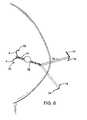
- FIG. 4shows a first anchor deployed within the breast.
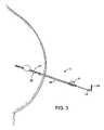
- FIG. 5shows a second anchor deployed within the breast.
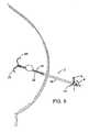
- FIG. 6shows a stiffener removed to provide a flexible proximal end.
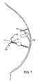
- FIG. 7shows the flexible, proximal portion taped to the breast.
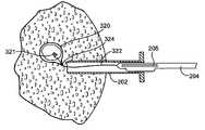
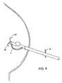
- FIG. 8shows a tissue removing device advanced over the needle and a cutting element deployed.
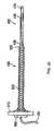
- FIG. 9is a perspective view of a combination introducer and suction sleeve, according to another embodiment of the present invention.
- FIG. 10is a side cross-sectional view of the combination introducer and suction sleeve of FIG. 9 .
- FIG. 11is a perspective view of the combination introducer and suction sleeve of FIG. 9 , with a trocar inserted therein.
- FIG. 12is a side cross-sectional view of the combination introducer and suction sleeve of FIG. 9 , illustrating exemplary structure with which the suction sleeve may attach to the interventional device.
- FIG. 13is a perspective cross-sectional view of the combination introducer and suction sleeve, attached to an exemplary interventional device
- FIG. 14is a perspective view of another embodiment of a suction sleeve according to the present invention, coupled to an exemplary interventional device.
- FIG. 15shows another guide element used to introduced a cutting device into the tissue.
- FIG. 16shows a piercing element removed from a lumen in the guide member.
- FIG. 17shows a cutting device introduced into the guide element.
- FIG. 18shows guide member retracted and anchored to the tissue with needles and an adhesive tape.
- FIG. 19shows a perspective view of another guide member having a window through which the cutting element extends when cutting the tissue.
- FIG. 20shows a tube which is cut to form a lip.
- FIG. 21is a cross-sectional view of FIG. 21 along line I-I.
- FIG. 22shows the tube of FIG. 21 covered with a shrink tube.
- FIG. 23is a cross-sectional view of FIG. 23 along line II-II with the addition of a cutting element shown in an expanded or bowed configuration.
- FIG. 24is a cross-sectional view of FIG. 23 along line III-III.
- FIG. 25shows another device for cutting or incising tissue.
- FIG. 26shows a removable core
- FIG. 27is a cross-sectional view of the device of FIG. 26 along line A-A.
- FIG. 28shows the removable core positioned within a sheath.
- FIG. 29shows the cutting or incising device positioned within the sheath.
- FIG. 30shows the cutting device positioned so that the cutting element will sweep around the tissue area being removed.
- FIG. 31shows a tissue removal device introduced through another incision.
- FIG. 32shows the tissue removal device attached to the tissue.
- FIGS. 33-35show use of the tissue cutting device to create a path for removing the tissue.
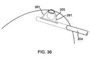
- FIG. 36shows the cutting device used to penetrate the tissue to create a tissue removal incision.
- FIG. 37shows the tissue contained within a tissue collection element having a tether which is coupled to the tissue cutter.
- FIG. 38shows the tissue cutter removed with the tether extending from the excised tissue.
- FIG. 39shows a side view of a tissue cutting device adjacent a tissue area to be removed.
- FIG. 40shows the cutting element beginning to sweep around the tissue area.
- FIG. 41shows the cutting element partially retracted to trap tissue between the cutting element and the shaft of the device.
- FIG. 42shows the tissue cutting device marking the tissue.
- a needle 2may be used to guide another medical device, such as a tissue cutting device 6 , when performing a procedure on the breast.
- a tissue cutting device 6Any suitable tissue cutting device may be used such as the devices disclosed in U.S. Pat. Nos. 6,440,147 and 6,022,362 which are also hereby incorporated by reference.
- the tissue cutting device 6has a cutting element 8 capable of assuming positions between collapsed and bowed positions. The tissue cutting device 6 is pivoted or rotated so that the cutting element 8 sweeps through and cuts the tissue along an arc.
- a tissue collection element 10may also be provided which collects the tissue being cut.
- the needle 2may also include a stiffener 4 which is used in the manner described in application Ser. No. 10/272,448, filed Oct. 16, 2002, which has been incorporated herein by reference.
- the needle 2may also have one or more indicators 14 to mark an angular position relative to the longitudinal axis 16 of the needle 2 .
- the indicator 14extends radially outward from the needle at a angle selected by the user.
- the indicator 14may also simply be a longitudinal stripe 18 or other marking on the shaft which indicates a particular angular orientation on the needle 2 .
- the indicator 14may provide information to the user regarding various parameters depending upon the procedure being performed. For example, when using the device 6 described above, the angular position, or positions, provides the user with the angular extent of the tissue to be removed.
- the indicators 14may be coupled to one more anchors 20 which are deployed to anchor the needle 2 .
- the anchor 20is preferably curved, such as J- or C-shaped, and extends radially to lie within the same angular orientation as the indicator 14 .
- An advantage of coupling the indicator 14 to the anchor 20is that anchor 20 itself provides information regarding the relative orientation or the needle 2 , anchor 20 and tissue area of interest. Thus, the anchor 20 itself may be one of the indicators 14 .
- the anchor 20 and indicator 14are preferably aligned at the same angular orientation, they may also be offset to account for the geometry of other devices used with the needle 2 .
- the indicators 14may also be independent of any anchoring elements.
- the needle 2may be placed in the breast and the indicators 14 could then be moved to selected angular position(s).
- the needle 2may also have depth markers 22 along the body.
- the anchor 20is preferably a stainless steel wire having a sharpened tip to pierce through the tissue. The orientation of the anchor 20 is partially guided by the geometry of the arc-shaped lumens (not shown) receiving the anchors 20 .
- the needle 2is introduced into the area of interest under suitable guidance such as ultrasound visualization. Once the needle 2 has been introduced in a desired or known orientation relative to the tissue area of interest, the entire needle 2 is rotated so that the first indicator 14 and marker 18 are aligned with a first angular position relative to the tissue area of interest. The first anchor 20 is then deployed into the tissue with the anchor 20 deployed at the selected angular orientation. The second indicator 14 is then rotated to a second selected angular orientation with respect to the area of interest.
- the second orientationis determined by visualizing the area of interest relative to the needle 2 and/or first anchor 20 to determine the appropriate location for the second anchor 20 .
- the second anchor 20is then deployed by advancing the anchor into the tissue.
- the needle 2 and anchors 20themselves provide visual landmarks for locating the area of interest.
- the markings on the needle 2 and the indicators 14also help to guide use of the tissue cutting device 6 as described herein.
- the stiffener 4is then removed to provide the flexible proximal portion.
- the flexible proximal portionmay be taped to the patient to prevent inadvertent contact as shown in FIG. 7 .
- the flexible conditionmay be maintained to provide the benefit described above such as the ability to pull from varying angles as compared to a conventional rigid needle.
- the tissue removal device 6may then be coupled to the needle 2 as shown in FIG. 8 and then advanced while being guided by the needle 2 .
- the needle 2may be introduced to a predetermined depth where the longitudinal stop 38 guides the depth of introduction of the tissue removal device. Of course, the needle 2 may be introduced deeper into the tissue with the user using the depth markings 40 on the needle 2 and/or tissue removal device 6 to determine the appropriate introduction depth for the tissue removal device 6 .
- the cutting element 8is then deployed to the bowed position and the cutting element 8 is swept through tissue to cut around the tissue area of interest.
- the tissueis then collected by the collection element 10 for removal.
- the device 6is then withdrawn and anchors 30 , which are described in more detail in application Ser. No. 10/272,448, filed Oct. 16, 2002, are retracted to permit withdrawal of the needle 2 as well.
- FIG. 9is a perspective view of a combination introducer and suction sleeve 902 .
- the sleeve 92may be used in the same manner as the guide members described herein and such uses is expressly incorporated here.
- FIG. 10is a side cross-sectional view thereof.
- the first external surface 904 of the combination introducer and suction sleeve 902may have a generally tapered or funnel shape, in that it defines a relatively narrow diameter distal end and a relatively wider proximal end. Such a generally funnel or tapered shape eases the introduction of the device 802 within tissue.
- the combination introducer and suction sleeve 902has a suction port 908 that opens to an internal lumen 916 defined by the internal surface 918 .
- the combination introducer and suction sleeve 902also includes a second external surface 912 that defines a tapered appearance. Defined within the first and/or second external surfaces 904 , 912 are a plurality of openings 906 that open to the internal lumen 916 . In FIGS. 9-11 , only the first external surface 904 defines such openings 906 , although the openings are not limited to this surface.
- the suction port 908is configured to couple with a vacuum line, as shown at 116 .
- the combination introducer and suction sleeve 902may further include structures to couple to one or more devices.
- Such coupling structure(s)may include, for example, a snap or interference fitting 914 and/or one or more O-rings, such as shown at 910 .
- FIG. 11is a perspective view of the combination introducer and suction sleeve of FIG. 9 , with a trocar 1102 inserted therein.
- the trocar 1102may be inserted into the combination introducer and suction sleeve 902 and the assembly may be packaged as a (preferably single use) unit.
- a physicianmay utilize the assembly as follows:
- An incision into tissueis made with a blade
- the trocar 1102may then be removed from the combination introducer and suction sleeve 902 and a desired (excisional RF, for example) device may then be inserted therethrough, with the shaft thereof disposed within and protruding from the internal lumen 916 ;
- the combination introducer and suction sleeve 902may then be pulled back until it contacts, snaps and/or otherwise locks onto the device, as shown at FIGS. 12 and 13 .
- FIGS. 12 and 13only the handle 102 of the device is shown, and the shaft 104 thereof is omitted for clarity of illustration. Examples of a tissue cutting device coupled to the combination introducer and suction sleeve 902 coupled thereto is shown in FIG. 14 ;
- a vacuum linesuch as shown at 116 , may then be attached to the suction port 908 ;
- the device with the combination introducer and suction sleeve 902 attached theretomay then be repositioned at, near, under or within the target lesion, as desired.
- This repositioningmay be carried out under ultrasound guidance, for example.
- the openings 906may aid with the ultrasound visualization.
- the combinationmay include other features and/or markings to increase the visibility thereof under various imaging modalities, and
- the physicianmay then continue with the intended procedure as per the instructions for use of the device utilized.
- the trocar 1102may be removed from the combination introducer and suction sleeve 902 and the desired RF device introduced and locked therein.
- the distal tip of the desired RF device protruding from the distal end of the combination introducer and suction sleeve 902may then be used to reach the intended biopsy site.
- a stopcockmay be attached to the suction port 908 instead of the suction line 116 and one or more beneficial agents (e.g., antibiotics, fibrin, lidocaine) may be delivered to a target site through the openings 906 .
- beneficial agentse.g., antibiotics, fibrin, lidocaine
- the present combination vacuum sleeve and suction sleeve 902may aid in positioning a biopsy or other interventional device where it is needed.
- interventional devicesthat include a rather bulky or high-drag distal end may be readily positioned at the intended site by means of the introducer functionality of the combination 902 .
- the combination 902is advantageous before the biopsy or other interventional procedure is started by easing the positioning of the biopsy instrument at or near the target site, it is also useful during the procedure itself, as it is effective in evacuating hot gasses and fluids from the biopsy cavity, thereby decreasing collateral tissue thermal damage.
- the same combinationmay then also be used to treat the cavity post-procedure by, for example, providing a ready-made pathway for the introduction of beneficial agents, compositions and/or cavity treatment devices to the cavity or lesion site.
- a guide member 202may be used to guide a cutting device 204 .
- the guide member 202may be any of the suitable guide members described herein including the needle 2 of FIGS. 1-8 or the introducer 902 of FIGS. 9-14 .
- the cutting device 204may be any of the cutting devices described herein or another suitable device such as those described in application Ser. No. 10/272,452, filed Oct. 16, 2002, which is hereby incorporated herein by reference.
- the cutting device 204has a cutting element 205 which bows outwardly when expanded.
- the guide member 202has a tubular body 206 and a removable penetrating element 208 having a sharp tip 210 for piercing tissue during introduction.
- the guide member 202also has a port 212 coupled to a vacuum source 214 for removing hot gasses generated during cutting.
- the penetrating element 208has a shaft 216 extending through a lumen 217 in the guide member 202 .
- the guide member 202may include one or more anchors 218 which holds the guide member 202 at the desired position.
- the anchor 218may simply be an adhesive strip 220 which the user peels away from the body and adheres to the skin.
- the anchor 218may also be another suitable anchor such as one or more needles 221 which are advanced into the tissue.
- the anchors 218help to resist movement of the guide member 202 so that the guide member 220 may be used to guide longitudinal and even rotational positioning of the cutting device 204 as explained herein.
- the anchor 218may also be a balloon 221 which is inflated to anchor the guide member.
- the guide member 202may include a stop 222 which prevents further advancement of the tissue cutting device 202 so that the device 204 remains in the same longitudinal position.
- the guide member 202may also include one or more angular indicators 224 which may be the anchors 218 .
- FIG. 19another guide member 202 A is shown which has a window 226 oriented in the desired direction of cutting. The window 226 guides the user by limiting and/or defining the cutting motion to help guide the cutting procedure.
- the use and structural features of the guide member 220 , indicators 224 , anchors 118 and stop 222may be the same or similar to those described in connection with FIGS. 1-8 .
- the cutting element 108preferably has an ultrasound marker 232 at an anticipated apex of the cutting element 108 when the cutting element 108 is expanded to help position the device.
- the apex 232does not necessarily correspond with the geometric middle of the cutting element 108 when the cutting element 108 is collapsed since only one end of the cutting element 108 may be moved to bow the cutting element 108 outward.
- the proximal end of the cutting element 108may be advanced distally to bow the cutting element 108 outward in which case the first marker 232 would appear to be closer to the proximal end when the cutting element 108 is collapsed.
- the cutting device 204may also include a second marker 234 and a third marker 236 which correspond to the ends of the cutting element 108 when the cutting element 108 is collapsed.
- the guide member 20may have a first marker 229 , corresponding to an anticipated apex 229 of the cutting element 108 , and a second marker 228 and a third marker 230 corresponding to the ends 228 , 230 of the cutting element 108 when collapsed.
- the guide member 202may help properly position the cutting device.
- any of the guide members or tissue cutting devices described herein, such as the needle 2may also have the ultrasound markers positioned in this manner.
- the cutting element and the guidemay be marked in any suitable manner.
- the cutting element or guidemay include a hollow area which would enhance the ultrasound signature.
- the markermay be designed to be easily visible when the cutting element 205 is powered at a level lower than the power level used during cutting.
- the cutting element 205may be designed to become more visible when an RF generator is switched to coagulation mode which has lower power than the cutting mode used when cutting tissue.
- the tissue cutting device 204may have a shaft 240 with an asymmetrical cross-sectional shape adjacent to the cutting element 205 to aid parting off the tissue when completing the cutting operation.
- the shaft 240is thicker in the direction in which the cutting element 205 expands as compared to the direction opposite cutter expansion. Stated another way, the shaft 240 may be thicker on a leading side 242 , which leads the cutting element when rotated in the direction of arrow 245 , than on an opposing or trailing side 244 .
- the shaft 240may also be thicker on the leading side in a direction substantially perpendicular to expansion of the cutting element 205 A (shown mounted to shaft 240 in the dotted-line position).
- Cutting element 205 Ais mounted to the shaft 240 in an orientation about 90 degrees from the orientation of the cutting element 205 .
- the cutting element 205 Amay be mounted to the shaft 240 in other orientations relative to the thicker part of the shaft such as any position between element 205 and element 205 A.
- the cutting element 205may be oriented and mounted on the shaft 240 in any manner which provides a thicker side within the first 90 degrees of the leading side compared to the shaft thickness in the 90 degrees trailing the cutting element 205 .
- the thicker part of the shaft 240is preferably at least 1.25 times, 1.50 times, or even 1.75 times thicker than the thinner part of the shaft 240 .
- the shaft 240may be formed in any suitable manner. Referring to FIGS. 20-24 , for example, a metallic tube 248 is cut to form a lip 250 which is bent outwardly to provide the thicker shaft section. The tube 248 is then covered with a shrink tube 252 and heated to bond the shrink tube 252 to the tube 248 . The shrink tube 252 covers the opening in the tube created by formation of the lip 252 . The shrink tube 252 also forms a beveled surface 254 which covers an opening 253 in the tube 248 created by the lip 250 .
- the guide member 202is introduced into the tissue to an appropriate depth relative to the tissue to be removed.
- the guide member 202may be used to help define and/or guide aspects of the cutting motion such as the depth of insertion and/or one or more angular positions indicating the angular extent of the targeted tissue.
- the ultrasound marker 229may be used to position the guide member 202 so that the anticipated apex of the cutting element 205 is positioned appropriately.
- the cutting window 226is positioned in the desired angular orientation which positions the tissue to be removed within the window 226 .
- the window 226may have an opening a bit larger than the anticipated requirement so that the window 226 guides, but not necessarily overly limits, the angular and longitudinal position of the cutting device 204 .
- the tissue penetrating element 208may be removed and the cutting device 204 is introduced into the guide member 202 .
- the guide member 202is then retracted a predetermined amount so that the guide member 202 is properly positioned to remove hot gases generated during RF cutting as described above.
- the guide memberdoes not, of course, need to be retracted.
- the cutting device 204is then used to cut around the tissue to be removed.
- the tissuemay be removed in a tissue collection element 10 (see FIG. 2 ).
- vacuum meansmay also be used to remove the tissue as now described and further described in application Ser. No. 10/796,328, filed Mar. 8, 2004, which has been incorporated herein by reference.
- the cutting device 204may be any suitable cutting device such as those described in application Ser. No. 10/272,452, filed Oct. 16, 2002.
- the core 400has an active element 440 configured to perform intra-tissue imaging and of relaying information back to a display device (shown in FIG. 30 ) via a communication channel, such as shown at reference numeral 460 .
- the communication channel 460may be wireless or may include, for example, optical fibers and/or electrical conductors.
- the active element 440may draw power from an internal battery (not shown) or from a power source, such as shown at reference numeral 480 .
- the active element 440may include an ultrasound transducer.
- the removable transducer core 400preferably includes a generally tubular shaft 430 .
- a proximal section 450is included near the proximal portion of the transducer core 400 .
- the excisional device 100 of FIG. 25includes an internal lumen 420 through which the removable transducer core 400 may be inserted.
- the excisional device 100is used once and disposed of, for safety and functional reasons.
- the removable transducer core 400may either be disposable or re-usable for a limited number of uses.
- a generally tubular member 110 of the excisional device 100includes a transducer window 410 .
- the proximal section 450 of the core 400preferably snaps into a locked configuration with the proximal end of the excisional device 100 .
- the active element 440 of the transducer core 400is aligned with and faces the transducer window 410 , to allow the active element 440 to image the lesion and the surrounding tissue therethrough.
- FIG. 26shows an embodiment of the removable core 400 according to the present invention.
- the removable core 400may advantageously be used independently of the excisional device 100 , the removable core 400 includes a distal tapered tip 470 , to allow it to easily penetrate soft tissue. Moreover, its thin profile allows the surgeon to insert the removable core 400 within soft tissue without, however, unduly damaging the tissue or making a large incision.
- the removable core 400allows the surgeon to precisely localize the lesion to be excised from within the tissue itself.
- the active element 440 of the removable core 400may include an ultrasound transducer and may be used alone or in addition to surface ultrasound to localize the lesion with a great degree of precision.
- FIG. 27shows a cross section of the embodiment of the excisional device 100 of FIG. 25 , taken along line AA′.
- the cutting tool 125is exposed through the transducer window 120 .
- the window 120may, as shown in FIG. 27 , include support guides 122 to support and guide the cutting tool 125 as it is outwardly extended and bowed.
- the tissue collection device 260for clarity, is not shown in either FIGS. 25 or 27 .
- the tubular member 110may include a recessed section 131 .
- the recessed sectionprovides space for the collected (e.g., bagged) tissue sample in the tissue collection device 260 when the excisional device is removed from the soft tissue mass.
- the collected tissue sample within the tissue collection device 260does not protrude from the generally smooth outer surface of the excisional device 100 upon retraction of the latter from the soft tissue mass from which the tissue sample is excised.
- the internal lumen 420allows the removable core 400 to slide therein and to properly position the active element 440 facing the transducer window 410 .
- FIG. 28shows the removable core 400 inserted within the expandable sheath 495 .
- the expandable sheath 495includes a proximal base section 510 .
- Attached to the proximal base section 510is a generally cylindrical expandable meshwork 500 of, for example, plastic or nylon fibers.
- the meshwork 500may be somewhat tapered at its distal end 520 , to provide a smooth transition between the expandable meshwork 500 and the removable core device 400 .
- the proximal section 450 of the core 400may snap-fit to the proximal base section 510 of the expandable sheath 495 , so as to be securely and removably attached thereto. As shown in FIG.
- the expandable meshwork 500expands just enough to accommodate the removable core 400 inserted therein.
- the expandable sheath 495 and removable core 400 assemblymay be inserted within the soft tissue together, to allow the surgeon to image the lesion prior to inserting the somewhat greater diameter excisional device 100 therein. Thereafter, the surgeon may retract the removable core 400 from the expandable sheath 495 , leaving the expandable sheath 495 in place within the soft tissue, such as the breast.
- FIG. 29shows another embodiment of a soft tissue excisional device assembly 600 according to the present invention.
- the removable core 400is inserted and secured within the excisional device 100 so that the active element 440 faces out of the transducer window 410 .
- the excisional device 100is removable from the expanded sheath 495 shown in FIG. 14 , while leaving the expanded sheath 495 in place within the soft tissue. In this manner, after retraction of the excisional device 100 from the sheath 495 , the sheath 495 remains in place within the soft tissue to allow other instruments to be inserted therethrough.
- the removable core 400may, after the excisional procedure proper, be re-inserted through the expanded sheath 495 to the excision site.
- the tissue collection device 260is not shown, for clarity but may be used in any manner described herein or in the applications or patents incorporated herein without departing from the scope of the invention.
- the excisional device 100is shown inserted within the expandable sheath 495 .
- the excisional device 100in FIG. 29 , is shown inserted within and past the distal end 520 of the meshwork 500 , so the distal portion of the excisional device 100 including the cutting element or tool 125 and the transducer window 410 extends therethrough.
- the meshwork 500in FIG. 30 , has expanded to accommodate the diameter of the excisional device 100 .
- the proximal portion of the excisional device 100may extend from the proximal base section of the expandable sheath 495 . This allows the push or turn knob 526 (a turn knob 526 shown in FIG. 29 ) to be manually accessible to the surgeon.
- a number of peripheral devicesmay be connected to the assembly 600 .
- a core power source 480which may be, for example, an electrical source for an ultrasound transducer, one or more data processing and display devices 550 on which the internal structure of the tissue imaged by the active element 440 of the core 400 may be displayed, suction means 490 , a cutting tool power source (a variable RF energy source, for example or any suitable RF power source found in most operating rooms), and/or other devices 590 .
- the suction device 490may provide a suction force to the window 120 through an internal lumen to facilitate cutting of the tissue by the cutting tool 125 . Any other suitable cutting or excisional device may be used in connection with the present invention such as those described in copending application Ser. No. 10/272,452, filed Oct. 16, 2002, which has been incorporated herein by reference.
- the vacuum meansmay be associated with the cutting tool 125 ( FIG. 25 ) or the cutting device 204 ( FIG. 17 ) or may be a separate removal device 300 as shown in FIG. 30 .
- the tissuemay also be removed through the same incision or a separate incision from the incision through which the cutting device 204 extends.
- the tissue removal device 300may have one or more suction ports 302 at a distal end 308 .
- the suction port 302is coupled to a lumen 304 which in turn is coupled to a vacuum source 306 .
- the suction port 302can be flared outwardly to enhance suction adherence and to help retract tissue away from the tissue being removed as shown in FIG. 32 .
- the end 308may have longitudinal slots (not shown) covered by an elastic cover 309 which permits the end 308 to flare outwardly in a manner similar to expandable trocars and cannulae as is known in the art.
- the end 308may be actuated with a thumb switch 310 or other suitable actuator.
- the tissue removal device 300may also directly grasp or pierce the tissue with piercing elements 311 , such as needles 313 , rather than relying on suction adherence.
- the tissue removal device 300may advance needles 312 into the tissue to anchor and grasp the tissue.
- the tissue removal device 300may be introduced through the same incision as the tissue cutting device 204 or may be introduced through a different incision.
- the usermay choose to introduce the cutting device 204 based primarily on the desired orientation of the cutting device 200 relative to the tissue area being removed.
- the usermay then choose the removal incision based on other factors such as proximity to the skin or for cosmetic considerations.
- the removal incisionmay be partially or completely created with the tissue cutting device 204 .
- the cutting element 205may be expanded and energized when the shaft is being withdrawn and/or advanced so that the cutting element 205 creates a tissue channel. This procedure may be repeated to create the desired channel such as an X- or Y-shaped channel.
- the cutting element 205may have a movable insulating sheath 260 which covers a portion of the cutting element 205 , such as the distal portion of the element 205 , to prevent inadvertent cutting of the tissue being removed when creating the tissue channel.
- a movable insulating sleeve 260is described in application Ser. No. 10/349,659, filed Jan. 23, 2003, which is hereby incorporated herein by reference.
- the cutting element 205may also be used to create a separate incision for removal of the tissue by cutting a channel directly from the area in which the tissue has been cut and extending outwardly from the severed portion.
- the cutting element 205is positioned so that further extension and bowing of the cutting element 205 will essentially create a path outwardly from the severed portion of the tissue. This procedure may be performed after severing the tissue in this area so that the cutting element 205 can be initially positioned without RF power.
- the ultrasound markers described herein, and in particular the marker near the apex of the cutting element 205 when expanded and bowed,are particularly useful in properly positioning the cutting element 205 at this time.
- the cutting element 205may then be powered with RF to partially or completely create the tissue channel. This procedure may be desirable when the cutting procedure causes the cutting element 205 to pass near the skin.
- the cutting device 204may also include a movable insulating sleeve 261 which covers part of the cutting element 205 , such as portions on the ends of the cutting element 205 , during this part of the procedure to reduce the excess lateral cutting during creation of the tissue channel.
- the tissueWhen removing the tissue, the tissue may be contained within a tissue collection element 320 released by the cutting device 204 when the tissue is severed or which is deployed by itself after excision of the tissue.
- the tissue collection element 320may simply trail the cutting element 205 similar to the patents and applications incorporated by reference herein in which the tissue collection element remains coupled to the device.
- FIG. 37shows the collection element 320 containing the tissue with a tether 322 extending from the tissue collection element 320 and being withdrawn as the cutting device 204 is removed.
- the tether 322may be used to guide advancement and engagement of the tissue removal device 300 .
- the tissue collection element 320may have a connector 324 which engages the removal device 300 with a suitable mechanical, magnetic or suction connection.
- the connector 324may be positioned at the end of the tether 322 so that engagement with the connector 324 is easily guided by the tether 322 .
- the tether 322may be particularly useful when removing the tissue through a separate incision since the tether 322 can be easily retrieved using a conventional suture snare or the like.
- the tether 322may also be used without the tissue collection element 320 by simply attaching the tether 320 to the tissue with a needle, screw 321 (see FIG. 37 ) or other suitable attachment feature.
- the tether 320may be delivered by the cutting device 204 or may be part of another device such as the tissue removal devices described herein.
- the tissue cutting device 204is shown and all features and aspects of the tissue cutting devices described herein are incorporated here.
- the tissue cutting device 204is shown sweeping around the tissue to be removed.
- the cutting element 205is then partially retracted so that only a small piece of tissue connects the tissue to be removed from the surrounding tissue as shown in FIG. 41 .
- the tissue cutting device 205may then be used to manipulate the tissue to assist or prepare the tissue for removal.
- the tissue cutting device 204may be designed to lock the cutting element 205 in the partially opened position of FIG. 41 to trap the tissue between the cutting element 205 and the shaft 240 so that the cutting device 204 may be used to manipulate the tissue.
- the tissuemay be manipulated while the tissue is being encapsulated in a tissue collection element or when the tissue is being engaged by any of the tissue removal devices described herein such as the device 300 .
- the cutting element 205is collapsed further to complete the cut.
- the tissue cutting device 204may also mark the tissue sample and/or the tissue surrounding the tissue sample as shown in FIG. 42 . Marking the tissue may assist in identifying the tissue for removal or to mark the tissue remaining in the body for subsequent therapy or treatment.
- the tissuemay be marked in any suitable manner such as those described in application Ser. No. 10/871,790, filed Jun. 17, 2004, which is incorporated herein by reference.
- the tissue cutting device 204may have one or more dye injection ports 330 to mark the tissue.
- the cutting devicemay also leave behind a marker, such as a spiral spring or coil as described above, to mark the tissue rather than marking the tissue with a dye or the like. It is understood that marking the tissue being removed and/or marking the tissue remaining in the body may be used in connection with any of the other features and aspects of the present invention including use with any of the tissue cutting or removal devices described herein.
Landscapes
- Health & Medical Sciences (AREA)
- Life Sciences & Earth Sciences (AREA)
- Surgery (AREA)
- Engineering & Computer Science (AREA)
- Veterinary Medicine (AREA)
- Heart & Thoracic Surgery (AREA)
- Medical Informatics (AREA)
- Molecular Biology (AREA)
- Biomedical Technology (AREA)
- Animal Behavior & Ethology (AREA)
- General Health & Medical Sciences (AREA)
- Public Health (AREA)
- Nuclear Medicine, Radiotherapy & Molecular Imaging (AREA)
- Pathology (AREA)
- Oncology (AREA)
- Radiology & Medical Imaging (AREA)
- Physics & Mathematics (AREA)
- Plasma & Fusion (AREA)
- Otolaryngology (AREA)
- Vascular Medicine (AREA)
- Oral & Maxillofacial Surgery (AREA)
- Orthopedic Medicine & Surgery (AREA)
- Surgical Instruments (AREA)
- Prostheses (AREA)
Abstract
Description
Claims (9)
Priority Applications (11)
| Application Number | Priority Date | Filing Date | Title |
|---|---|---|---|
| US10/923,511US7517348B2 (en) | 1998-09-03 | 2004-08-20 | Devices and methods for performing procedures on a breast |
| EP05858540AEP1793757A4 (en) | 2004-08-20 | 2005-08-19 | Devices and methods for performing procedures on a breast |
| JP2007536686AJP2008510596A (en) | 2004-08-20 | 2005-08-19 | APPARATUS AND METHOD FOR PERFORMING TREATMENTS ON THE BREAST (Related Application) This application is a co-pending application of application number 10 / 732,670 filed on December 9, 2003, Application No. 10 / 272,448, partly pending application, application No. 10 / 796,328, partly pending application, filed March 8, 2004, No. 10 / 796,328 is a partially pending application of application number 09 / 417,520 filed on Oct. 13, 1999 which is now US Pat. No. 6,423,081. This application number 09 / 417,520 is a divisional application of application number 09 / 146,743 filed on September 3, 1998, currently US Pat. No. 6,022,362. . The entirety of all the above related applications is hereby incorporated by reference. |
| CA002575835ACA2575835A1 (en) | 2004-08-20 | 2005-08-19 | Devices and methods for performing procedures on a breast |
| PCT/US2005/029503WO2007035177A2 (en) | 2004-08-20 | 2005-08-19 | Devices and methods for performing procedures on a breast |
| US11/740,847US20070203427A1 (en) | 1998-09-03 | 2007-04-26 | Devices and methods for performing procedures on a breast |
| US11/740,858US20070203428A1 (en) | 1998-09-03 | 2007-04-26 | Devices and methods for performing procedures on a breast |
| US11/740,855US20070197934A1 (en) | 1998-09-03 | 2007-04-26 | Devices and methods for performing procedures on a breast |
| US13/525,912US9521992B2 (en) | 2002-10-16 | 2012-06-18 | Devices and methods for performing procedures on a breast |
| US13/668,144US20130226028A1 (en) | 1998-09-03 | 2012-11-02 | Devices and methods for performing procedures on a breast |
| US13/895,303US20130253370A1 (en) | 2002-10-16 | 2013-05-15 | Devices and methods for performing procedures on a breast |
Applications Claiming Priority (6)
| Application Number | Priority Date | Filing Date | Title |
|---|---|---|---|
| US09/146,743US6022362A (en) | 1998-09-03 | 1998-09-03 | Excisional biopsy devices and methods |
| US09/417,520US6423081B1 (en) | 1998-09-03 | 1999-10-13 | Excisional biopsy devices and methods |
| US10/272,448US6936014B2 (en) | 2002-10-16 | 2002-10-16 | Devices and methods for performing procedures on a breast |
| US10/732,670US7329253B2 (en) | 2003-12-09 | 2003-12-09 | Suction sleeve and interventional devices having such a suction sleeve |
| US10/796,328US7303531B2 (en) | 1998-09-03 | 2004-03-08 | Excisional biopsy devices and methods |
| US10/923,511US7517348B2 (en) | 1998-09-03 | 2004-08-20 | Devices and methods for performing procedures on a breast |
Related Parent Applications (3)
| Application Number | Title | Priority Date | Filing Date |
|---|---|---|---|
| US10/272,448Continuation-In-PartUS6936014B2 (en) | 1998-09-03 | 2002-10-16 | Devices and methods for performing procedures on a breast |
| US10/732,670Continuation-In-PartUS7329253B2 (en) | 1998-09-03 | 2003-12-09 | Suction sleeve and interventional devices having such a suction sleeve |
| US10/796,328Continuation-In-PartUS7303531B2 (en) | 1998-09-03 | 2004-03-08 | Excisional biopsy devices and methods |
Related Child Applications (3)
| Application Number | Title | Priority Date | Filing Date |
|---|---|---|---|
| US11/740,858DivisionUS20070203428A1 (en) | 1998-09-03 | 2007-04-26 | Devices and methods for performing procedures on a breast |
| US11/740,855DivisionUS20070197934A1 (en) | 1998-09-03 | 2007-04-26 | Devices and methods for performing procedures on a breast |
| US11/740,847DivisionUS20070203427A1 (en) | 1998-09-03 | 2007-04-26 | Devices and methods for performing procedures on a breast |
Publications (2)
| Publication Number | Publication Date |
|---|---|
| US20050119652A1 US20050119652A1 (en) | 2005-06-02 |
| US7517348B2true US7517348B2 (en) | 2009-04-14 |
Family
ID=37889279
Family Applications (7)
| Application Number | Title | Priority Date | Filing Date |
|---|---|---|---|
| US10/923,511Expired - Fee RelatedUS7517348B2 (en) | 1998-09-03 | 2004-08-20 | Devices and methods for performing procedures on a breast |
| US11/740,855AbandonedUS20070197934A1 (en) | 1998-09-03 | 2007-04-26 | Devices and methods for performing procedures on a breast |
| US11/740,847AbandonedUS20070203427A1 (en) | 1998-09-03 | 2007-04-26 | Devices and methods for performing procedures on a breast |
| US11/740,858AbandonedUS20070203428A1 (en) | 1998-09-03 | 2007-04-26 | Devices and methods for performing procedures on a breast |
| US13/525,912Expired - Fee RelatedUS9521992B2 (en) | 2002-10-16 | 2012-06-18 | Devices and methods for performing procedures on a breast |
| US13/668,144AbandonedUS20130226028A1 (en) | 1998-09-03 | 2012-11-02 | Devices and methods for performing procedures on a breast |
| US13/895,303AbandonedUS20130253370A1 (en) | 2002-10-16 | 2013-05-15 | Devices and methods for performing procedures on a breast |
Family Applications After (6)
| Application Number | Title | Priority Date | Filing Date |
|---|---|---|---|
| US11/740,855AbandonedUS20070197934A1 (en) | 1998-09-03 | 2007-04-26 | Devices and methods for performing procedures on a breast |
| US11/740,847AbandonedUS20070203427A1 (en) | 1998-09-03 | 2007-04-26 | Devices and methods for performing procedures on a breast |
| US11/740,858AbandonedUS20070203428A1 (en) | 1998-09-03 | 2007-04-26 | Devices and methods for performing procedures on a breast |
| US13/525,912Expired - Fee RelatedUS9521992B2 (en) | 2002-10-16 | 2012-06-18 | Devices and methods for performing procedures on a breast |
| US13/668,144AbandonedUS20130226028A1 (en) | 1998-09-03 | 2012-11-02 | Devices and methods for performing procedures on a breast |
| US13/895,303AbandonedUS20130253370A1 (en) | 2002-10-16 | 2013-05-15 | Devices and methods for performing procedures on a breast |
Country Status (5)
| Country | Link |
|---|---|
| US (7) | US7517348B2 (en) |
| EP (1) | EP1793757A4 (en) |
| JP (1) | JP2008510596A (en) |
| CA (1) | CA2575835A1 (en) |
| WO (1) | WO2007035177A2 (en) |
Cited By (24)
| Publication number | Priority date | Publication date | Assignee | Title |
|---|---|---|---|---|
| US8162889B2 (en) | 2005-07-11 | 2012-04-24 | Covidien Ag | Safety reset key and needle assembly |
| US20120296239A1 (en)* | 2011-05-16 | 2012-11-22 | Tyco Healthcare Group Lp | Destruction of Vessel Walls for Energy-Based Vessel Sealing Enhancement |
| US8834417B2 (en) | 2005-06-06 | 2014-09-16 | Covidien Ag | Needle assembly with removable depth stop |
| US20150105627A1 (en)* | 2012-06-21 | 2015-04-16 | Olympus Corporation | Access port |
| US9053914B2 (en) | 2011-06-03 | 2015-06-09 | Micromass Uk Limited | Diathermy knife ionisation source |
| USRE46855E1 (en) | 2009-06-26 | 2018-05-22 | Orthovita, Inc. | K-wire and method for surgical procedures |
| USRE46872E1 (en) | 2009-06-26 | 2018-05-29 | Orthovita, Inc. | Guidewire and method for surgical procedures |
| US10149700B2 (en) | 2013-08-12 | 2018-12-11 | Jan R. Lau | 3 dimensional simultaneous multiple core biopsy or fiducial marker placement device and methods |
| US10777398B2 (en) | 2015-03-06 | 2020-09-15 | Micromass Uk Limited | Spectrometric analysis |
| US10777397B2 (en) | 2015-03-06 | 2020-09-15 | Micromass Uk Limited | Inlet instrumentation for ion analyser coupled to rapid evaporative ionisation mass spectrometry (“REIMS”) device |
| US10916415B2 (en) | 2015-03-06 | 2021-02-09 | Micromass Uk Limited | Liquid trap or separator for electrosurgical applications |
| US10978284B2 (en) | 2015-03-06 | 2021-04-13 | Micromass Uk Limited | Imaging guided ambient ionisation mass spectrometry |
| US11031222B2 (en) | 2015-03-06 | 2021-06-08 | Micromass Uk Limited | Chemically guided ambient ionisation mass spectrometry |
| US11031223B2 (en) | 2015-09-29 | 2021-06-08 | Micromass Uk Limited | Capacitively coupled REIMS technique and optically transparent counter electrode |
| US11037774B2 (en) | 2015-03-06 | 2021-06-15 | Micromass Uk Limited | Physically guided rapid evaporative ionisation mass spectrometry (“REIMS”) |
| US11139156B2 (en) | 2015-03-06 | 2021-10-05 | Micromass Uk Limited | In vivo endoscopic tissue identification tool |
| US11239066B2 (en) | 2015-03-06 | 2022-02-01 | Micromass Uk Limited | Cell population analysis |
| US11264223B2 (en) | 2015-03-06 | 2022-03-01 | Micromass Uk Limited | Rapid evaporative ionisation mass spectrometry (“REIMS”) and desorption electrospray ionisation mass spectrometry (“DESI-MS”) analysis of swabs and biopsy samples |
| US11270876B2 (en) | 2015-03-06 | 2022-03-08 | Micromass Uk Limited | Ionisation of gaseous samples |
| US11282688B2 (en) | 2015-03-06 | 2022-03-22 | Micromass Uk Limited | Spectrometric analysis of microbes |
| US11289320B2 (en) | 2015-03-06 | 2022-03-29 | Micromass Uk Limited | Tissue analysis by mass spectrometry or ion mobility spectrometry |
| US11342170B2 (en) | 2015-03-06 | 2022-05-24 | Micromass Uk Limited | Collision surface for improved ionisation |
| US11367605B2 (en) | 2015-03-06 | 2022-06-21 | Micromass Uk Limited | Ambient ionization mass spectrometry imaging platform for direct mapping from bulk tissue |
| US11454611B2 (en) | 2016-04-14 | 2022-09-27 | Micromass Uk Limited | Spectrometric analysis of plants |
Families Citing this family (44)
| Publication number | Priority date | Publication date | Assignee | Title |
|---|---|---|---|---|
| US6936014B2 (en)* | 2002-10-16 | 2005-08-30 | Rubicor Medical, Inc. | Devices and methods for performing procedures on a breast |
| US7041101B2 (en)* | 1999-12-27 | 2006-05-09 | Neothermia Corporation | Electrosurgical accessing of tissue with controlled collateral thermal phenomena |
| US8172770B2 (en)* | 2005-09-28 | 2012-05-08 | Suros Surgical Systems, Inc. | System and method for minimally invasive disease therapy |
| US7905857B2 (en) | 2005-07-11 | 2011-03-15 | Covidien Ag | Needle assembly including obturator with safety reset |
| US7850650B2 (en) | 2005-07-11 | 2010-12-14 | Covidien Ag | Needle safety shield with reset |
| US7731692B2 (en) | 2005-07-11 | 2010-06-08 | Covidien Ag | Device for shielding a sharp tip of a cannula and method of using the same |
| US10548659B2 (en) | 2006-01-17 | 2020-02-04 | Ulthera, Inc. | High pressure pre-burst for improved fluid delivery |
| US9486274B2 (en) | 2005-09-07 | 2016-11-08 | Ulthera, Inc. | Dissection handpiece and method for reducing the appearance of cellulite |
| US9011473B2 (en) | 2005-09-07 | 2015-04-21 | Ulthera, Inc. | Dissection handpiece and method for reducing the appearance of cellulite |
| US8518069B2 (en) | 2005-09-07 | 2013-08-27 | Cabochon Aesthetics, Inc. | Dissection handpiece and method for reducing the appearance of cellulite |
| US9358033B2 (en) | 2005-09-07 | 2016-06-07 | Ulthera, Inc. | Fluid-jet dissection system and method for reducing the appearance of cellulite |
| US7654735B2 (en) | 2005-11-03 | 2010-02-02 | Covidien Ag | Electronic thermometer |
| US8298243B2 (en) | 2007-07-30 | 2012-10-30 | Tyco Healthcare Group Lp | Combination wire electrode and tube electrode polypectomy device |
| US8439940B2 (en) | 2010-12-22 | 2013-05-14 | Cabochon Aesthetics, Inc. | Dissection handpiece with aspiration means for reducing the appearance of cellulite |
| US8357104B2 (en) | 2007-11-01 | 2013-01-22 | Coviden Lp | Active stylet safety shield |
| CA2713898C (en) | 2008-01-31 | 2017-05-02 | Tyco Healthcare Group, Lp | Polyp removal device and method of use |
| WO2010022060A1 (en) | 2008-08-19 | 2010-02-25 | Wilson-Cook Medical Inc. | Apparatus for removing lymph nodes or anchoring into tissue during a translumenal procedure |
| US9095328B2 (en) | 2008-12-12 | 2015-08-04 | Boston Scientific Scimed, Inc. | Endoscopes having multiple lumens for tissue acquisition and removal and related methods of use |
| USD621933S1 (en)* | 2009-03-23 | 2010-08-17 | Karl Storz Gmbh & Co. Kg | Medical instrument |
| USD622382S1 (en)* | 2009-04-03 | 2010-08-24 | Karl Storz Gmbh & Co. Kg | Dilatator |
| WO2011005971A1 (en)* | 2009-07-09 | 2011-01-13 | Cook Incorporated | Spring action medical device |
| US11096708B2 (en) | 2009-08-07 | 2021-08-24 | Ulthera, Inc. | Devices and methods for performing subcutaneous surgery |
| US9358064B2 (en) | 2009-08-07 | 2016-06-07 | Ulthera, Inc. | Handpiece and methods for performing subcutaneous surgery |
| US20110054459A1 (en)* | 2009-08-27 | 2011-03-03 | Vivant Medical, Inc. | Ecogenic Cooled Microwave Ablation Antenna |
| WO2011062736A1 (en)* | 2009-11-17 | 2011-05-26 | Cook Incorporated | Deflectable biopsy device |
| US20110125054A1 (en)* | 2009-11-25 | 2011-05-26 | Robert Clements | Device, system and method for multiple core biopsy |
| US9265913B2 (en)* | 2010-09-22 | 2016-02-23 | Vital 5, Llc | Catheter assembly |
| US8480710B2 (en)* | 2010-11-04 | 2013-07-09 | Covidien Lp | Wound closure device including suction step sleeve |
| WO2013005500A1 (en)* | 2011-07-06 | 2013-01-10 | オリンパスメディカルシステムズ株式会社 | Sampling device |
| WO2013046962A1 (en)* | 2011-09-27 | 2013-04-04 | テルモ株式会社 | Puncture device |
| WO2013101641A2 (en)* | 2011-12-29 | 2013-07-04 | Rotation Medical, Inc. | Anatomical location markers and methods of use in positioning sheet-like materials during surgery |
| CN102908181B (en)* | 2012-10-31 | 2015-02-04 | 裴元民 | Breast mass positioning needle |
| WO2014100349A1 (en) | 2012-12-19 | 2014-06-26 | Merit Medical Systems, Inc. | Biopsy device and method of use |
| EP3868304A1 (en) | 2013-01-18 | 2021-08-25 | Merit Medical Systems, Inc. | Biopsy device with transfer of kinetic energy to the needle assembly |
| EP2862533B1 (en)* | 2013-10-18 | 2019-09-18 | Erbe Elektromedizin GmbH | Adapter element, HF surgery instrument, adapter set and system |
| CN114366181B (en)* | 2013-12-13 | 2024-08-02 | 直观外科手术操作公司 | Telescopic biopsy needle |
| ES2746123T3 (en) | 2014-01-17 | 2020-03-04 | Merit Medical Systems Inc | Flush Cut Biopsy Needle Mount |
| US10813685B2 (en) | 2014-09-25 | 2020-10-27 | Covidien Lp | Single-handed operable surgical instrument including loop electrode with integrated pad electrode |
| FR3028407B1 (en)* | 2014-11-14 | 2020-10-02 | Clariance | SECURE GUIDANCE DEVICE |
| US10213091B2 (en)* | 2015-02-13 | 2019-02-26 | University Of Dammam | System, method, and apparatus for visualizing and identifying pathological tissue |
| DE102015012964B4 (en)* | 2015-10-08 | 2018-12-27 | Karl Storz Se & Co. Kg | Access system for endoscopic operations |
| US11197709B2 (en) | 2017-03-13 | 2021-12-14 | Medtronic Advanced Energy Llc | Electrosurgical system |
| EP3456379B1 (en)* | 2017-09-15 | 2020-03-11 | Sorin CRM SAS | Explantation assembly for retrieving intracorporeal autonomous capsules |
| CN111938790A (en)* | 2020-09-09 | 2020-11-17 | 高胜利 | Clinical drainage piercing depth that uses of antiskid formula intracardiac branch of academic or vocational study |
Citations (175)
| Publication number | Priority date | Publication date | Assignee | Title |
|---|---|---|---|---|
| US1813902A (en) | 1928-01-18 | 1931-07-14 | Liebel Flarsheim Co | Electrosurgical apparatus |
| US2816552A (en) | 1954-06-29 | 1957-12-17 | Roy D Hoffman | Teat bistoury with improved cutter blade adjusting means |
| US3320957A (en) | 1964-05-21 | 1967-05-23 | Sokolik Edward | Surgical instrument |
| GB1214707A (en) | 1968-04-18 | 1970-12-02 | Electronic & X Ray Applic Ltd | Improvements in or relating to ancillary apparatus for use with x-ray apparatus |
| DE1952844A1 (en) | 1969-10-14 | 1971-05-13 | Joachim Schlichting | Propulsion system for control purposes and spacecraft made up of several bodies that can be moved by impact and people in space |
| US3732858A (en) | 1968-09-16 | 1973-05-15 | Surgical Design Corp | Apparatus for removing blood clots, cataracts and other objects from the eye |
| US3749085A (en) | 1970-06-26 | 1973-07-31 | J Willson | Vascular tissue removing device |
| GB1331468A (en) | 1969-10-03 | 1973-09-26 | Bosch Gmbh Robert | Connection connecting electrical conductors |
| US3910279A (en) | 1973-06-20 | 1975-10-07 | Olympus Optical Co | Electrosurgical instrument |
| US3955578A (en) | 1974-12-23 | 1976-05-11 | Cook Inc. | Rotatable surgical snare |
| US3971950A (en) | 1975-04-14 | 1976-07-27 | Xerox Corporation | Independent compression and positioning device for use in mammography |
| DE2610111A1 (en) | 1976-03-11 | 1977-09-15 | Friedrich Guenter Schwarz | Body holder for X:ray examination - has housing permeable to X:rays over part of body and connected to fluid source |
| US4099518A (en) | 1976-05-10 | 1978-07-11 | Baylis Shelby M | Biopsy apparatus |
| US4130112A (en) | 1976-11-15 | 1978-12-19 | The United States Of America As Represented By The Administrator Of The National Aeronautics And Space Administration | Coupling apparatus for ultrasonic medical diagnostic system |
| FR2275226B3 (en) | 1974-05-30 | 1978-12-29 | Wolf Gmbh Richard | |
| US4245653A (en) | 1979-01-02 | 1981-01-20 | Kenneth Weaver | Method and apparatus for obtaining specimens of endometrial tissue |
| US4347850A (en) | 1980-03-19 | 1982-09-07 | Indianapolis Center For Advanced Research, Inc. | Direct water coupling device for ultrasound breast scanning in a supine position |
| US4347846A (en) | 1979-12-07 | 1982-09-07 | Porges | Surgical extractor |
| US4434799A (en) | 1982-03-02 | 1984-03-06 | Siemens Ag | Ultrasound apparatus for medical examinations |
| US4509368A (en) | 1981-06-22 | 1985-04-09 | The Commonwealth Of Australia | Ultrasound tomography |
| US4563768A (en) | 1983-07-11 | 1986-01-07 | University Of Virginia Alumni Patents Foundations | Mamographic device using localized compression cone |
| SU1235497A1 (en) | 1984-04-11 | 1986-06-07 | Ташкентский Ордена Трудового Красного Знамени Государственный Медицинский Институт | Arrangement for dissection of stenosis of tubular organs |
| JPS6129733B2 (en) | 1980-05-30 | 1986-07-09 | Tokyo Shibaura Electric Co | |
| US4611594A (en) | 1984-04-11 | 1986-09-16 | Northwestern University | Medical instrument for containment and removal of calculi |
| US4650466A (en) | 1985-11-01 | 1987-03-17 | Angiobrade Partners | Angioplasty device |
| US4691333A (en) | 1985-12-27 | 1987-09-01 | Gabriele Joseph M | Breast compression and needle localization apparatus |
| SU1355266A1 (en) | 1985-12-05 | 1987-11-30 | 3. Янгибаев | Arrangement for dissection of constrictions of tubular organs |
| GB2204496A (en) | 1987-05-15 | 1988-11-16 | Syntex Inc | Device for collecting biological material |
| US4829184A (en) | 1984-06-25 | 1989-05-09 | Nelson Robert S | Reflective, transmissive high resolution imaging apparatus |
| US4890611A (en) | 1988-04-05 | 1990-01-02 | Thomas J. Fogarty | Endarterectomy apparatus and method |
| US4903696A (en) | 1988-10-06 | 1990-02-27 | Everest Medical Corporation | Electrosurgical generator |
| US4966604A (en) | 1989-01-23 | 1990-10-30 | Interventional Technologies Inc. | Expandable atherectomy cutter with flexibly bowed blades |
| US5009660A (en) | 1989-09-15 | 1991-04-23 | Visx, Incorporated | Gas purging, eye fixation hand piece |
| US5056523A (en) | 1989-11-22 | 1991-10-15 | Board Of Regents, The University Of Texas System | Precision breast lesion localizer |
| US5071424A (en) | 1989-08-18 | 1991-12-10 | Evi Corporation | Catheter atherotome |
| US5083570A (en) | 1990-06-18 | 1992-01-28 | Mosby Richard A | Volumetric localization/biopsy/surgical device |
| US5100423A (en) | 1990-08-21 | 1992-03-31 | Medical Engineering & Development Institute, Inc. | Ablation catheter |
| DE4037387A1 (en) | 1990-11-22 | 1992-05-27 | Kari Dr Richter | Object imaging display for ultrasonic sonic scanning computer tomograph - superimposes echoes of primary radiation into summation image |
| US5147355A (en) | 1988-09-23 | 1992-09-15 | Brigham And Womens Hospital | Cryoablation catheter and method of performing cryoablation |
| US5152293A (en) | 1991-07-01 | 1992-10-06 | Northwestern University | Finger-mounted intraoperative imaging device |
| US5156610A (en) | 1989-08-18 | 1992-10-20 | Evi Corporation | Catheter atherotome |
| WO1992020291A1 (en) | 1991-05-24 | 1992-11-26 | Applied Medical Resources, Inc. | Articulating tissue cutter assembly |
| US5171321A (en) | 1992-03-09 | 1992-12-15 | Davis Joseph P | Nipple prosthesis and method of making the same |
| US5174296A (en) | 1990-03-29 | 1992-12-29 | Fujitsu Limited | Ultrasonic probe having a piezoelectrical element |
| US5176688A (en) | 1991-07-17 | 1993-01-05 | Perinchery Narayan | Stone extractor and method |
| US5181916A (en) | 1991-04-26 | 1993-01-26 | Sorenson Laboratories, Inc. | Surgical probe and smoke eliminator |
| US5192291A (en) | 1992-01-13 | 1993-03-09 | Interventional Technologies, Inc. | Rotationally expandable atherectomy cutter assembly |
| US5203773A (en) | 1991-10-18 | 1993-04-20 | United States Surgical Corporation | Tissue gripping apparatus for use with a cannula or trocar assembly |
| US5211651A (en) | 1989-08-18 | 1993-05-18 | Evi Corporation | Catheter atherotome |
| US5217479A (en) | 1991-02-14 | 1993-06-08 | Linvatec Corporation | Surgical cutting instrument |
| US5217451A (en) | 1991-05-24 | 1993-06-08 | Dexide, Inc. | Gear activated trocar assembly |
| US5224945A (en) | 1992-01-13 | 1993-07-06 | Interventional Technologies, Inc. | Compressible/expandable atherectomy cutter |
| US5224488A (en) | 1992-08-31 | 1993-07-06 | Neuffer Francis H | Biopsy needle with extendable cutting means |
| US5224944A (en) | 1991-01-07 | 1993-07-06 | Elliott Martin P | Aspiration tip for a cautery handpiece |
| US5234428A (en) | 1991-06-11 | 1993-08-10 | Kaufman David I | Disposable electrocautery/cutting instrument with integral continuous smoke evacuation |
| US5282484A (en) | 1989-08-18 | 1994-02-01 | Endovascular Instruments, Inc. | Method for performing a partial atherectomy |
| US5308321A (en) | 1992-05-05 | 1994-05-03 | Castro Donna J | Retainer assisted by vacuum expansion system |
| US5318565A (en) | 1992-11-12 | 1994-06-07 | Daniel B. Kuriloff | Suction cautery dissector |
| US5318576A (en) | 1992-12-16 | 1994-06-07 | Plassche Jr Walter M | Endovascular surgery systems |
| US5325860A (en) | 1991-11-08 | 1994-07-05 | Mayo Foundation For Medical Education And Research | Ultrasonic and interventional catheter and method |
| US5386447A (en) | 1992-09-23 | 1995-01-31 | Fischer Imaging Corporation | Mammographic screening and biopsy apparatus |
| WO1995002370A3 (en) | 1993-07-15 | 1995-03-09 | Aws Shakir Mustafa Salim | Tunnelling catheter |
| WO1995002371A3 (en) | 1993-07-15 | 1995-03-09 | Aws Shakir Mustafa Salim | Rectal and rectosigmoid cancer tunnelling umbrella |
| US5403311A (en) | 1993-03-29 | 1995-04-04 | Boston Scientific Corporation | Electro-coagulation and ablation and other electrotherapeutic treatments of body tissue |
| US5409497A (en) | 1991-03-11 | 1995-04-25 | Fischer Imaging Corporation | Orbital aiming device for mammo biopsy |
| US5415656A (en) | 1993-09-28 | 1995-05-16 | American Medical Systems, Inc. | Electrosurgical apparatus |
| US5417697A (en) | 1993-07-07 | 1995-05-23 | Wilk; Peter J. | Polyp retrieval assembly with cauterization loop and suction web |
| US5437280A (en) | 1993-09-20 | 1995-08-01 | Hussman; Karl L. | Magnetic resonance breast localizer |
| US5441510A (en) | 1993-09-01 | 1995-08-15 | Technology Development Center | Bi-axial cutter apparatus for catheter |
| WO1995021582A1 (en) | 1994-02-15 | 1995-08-17 | Hussman Karl L | Localizer |
| US5451789A (en) | 1993-07-19 | 1995-09-19 | Board Of Regents, The University Of Texas System | High performance positron camera |
| US5458597A (en) | 1993-11-08 | 1995-10-17 | Zomed International | Device for treating cancer and non-malignant tumors and methods |
| US5460602A (en) | 1989-01-23 | 1995-10-24 | Shapira; Nadiv | Smoke evacuator for smoke generating devices |
| US5527326A (en) | 1992-12-29 | 1996-06-18 | Thomas J. Fogarty | Vessel deposit shearing apparatus |
| US5554163A (en) | 1995-04-27 | 1996-09-10 | Shturman Cardiology Systems, Inc. | Atherectomy device |
| WO1996029946A1 (en) | 1995-03-24 | 1996-10-03 | Board Of Regents Of The University Of Nebraska | Apparatus for ablation of tissue masses |
| US5590166A (en) | 1995-12-28 | 1996-12-31 | Instrumentarium Corporation | Mammography unit |
| DE19528440A1 (en) | 1995-08-02 | 1997-02-06 | Harald Dr Med Kuebler | Surgical cutting instrument for tissue removal - has cutting device enclosed by tubular end section of instrument during insertion and curved transverse to its axial direction in working position |
| US5611803A (en) | 1994-12-22 | 1997-03-18 | Urohealth Systems, Inc. | Tissue segmentation device |
| US5630426A (en) | 1995-03-03 | 1997-05-20 | Neovision Corporation | Apparatus and method for characterization and treatment of tumors |
| US5632754A (en) | 1994-12-23 | 1997-05-27 | Devices For Vascular Intervention | Universal catheter with interchangeable work element |
| US5660185A (en) | 1995-04-13 | 1997-08-26 | Neovision Corporation | Image-guided biopsy apparatus with enhanced imaging and methods |
| US5662109A (en) | 1990-12-14 | 1997-09-02 | Hutson; William H. | Method and system for multi-dimensional imaging and analysis for early detection of diseased tissue |
| US5672172A (en) | 1994-06-23 | 1997-09-30 | Vros Corporation | Surgical instrument with ultrasound pulse generator |
| GB2311468A (en) | 1996-03-27 | 1997-10-01 | Valleylab Inc | Electrosurgical interstitial resector |
| US5683384A (en) | 1993-11-08 | 1997-11-04 | Zomed | Multiple antenna ablation apparatus |
| US5702405A (en) | 1994-11-30 | 1997-12-30 | Siemens Aktiengesellschaft | Stereotactic auxiliary attachment for a tomography apparatus for tomogram guided implementation of a biopsy |
| US5706327A (en) | 1996-02-09 | 1998-01-06 | Trex Medical Corporation | Method and apparatus for mammographic compression |
| US5709697A (en) | 1995-11-22 | 1998-01-20 | United States Surgical Corporation | Apparatus and method for removing tissue |
| US5722949A (en) | 1994-08-26 | 1998-03-03 | Sanese Medical Corporation | Fluid supply and suction apparatus and method |
| WO1998008441A1 (en) | 1996-08-29 | 1998-03-05 | Ethicon Endo-Surgery | Methods and devices for collection of soft tissue |
| EP0829232A2 (en) | 1996-08-29 | 1998-03-18 | City Of Hope | Minimally invasive biopsy device |
| US5741271A (en) | 1991-11-05 | 1998-04-21 | Nakao; Naomi L. | Surgical retrieval assembly and associated method |
| NL1004723C2 (en) | 1996-12-06 | 1998-06-09 | Ronald Willem De Haan | Diathermic loop provided with electrically conductive cutting wire |
| US5766191A (en) | 1992-04-07 | 1998-06-16 | Johns Hopkins University | Percutaneous mechanical fragmentation catheter system |
| US5776177A (en) | 1992-12-21 | 1998-07-07 | Macwhinnie; Virginia | C-shaped heat pack for thermal treatment of breast |
| US5794626A (en) | 1994-08-18 | 1998-08-18 | Kieturakis; Maciej J. | Excisional stereotactic apparatus |
| US5797907A (en) | 1989-11-06 | 1998-08-25 | Mectra Labs, Inc. | Electrocautery cutter |
| US5800484A (en) | 1995-08-15 | 1998-09-01 | Rita Medical Systems, Inc. | Multiple antenna ablation apparatus with expanded electrodes |
| US5800431A (en) | 1996-10-11 | 1998-09-01 | Brown; Robert H. | Electrosurgical tool with suction and cautery |
| US5805665A (en) | 1995-06-05 | 1998-09-08 | Nelson; Robert S. | Anthropomorphic mammography phantoms |
| US5810742A (en) | 1994-10-24 | 1998-09-22 | Transcan Research & Development Co., Ltd. | Tissue characterization based on impedance images and on impedance measurements |
| US5820552A (en) | 1996-07-12 | 1998-10-13 | United States Surgical Corporation | Sonography and biopsy apparatus |
| US5830214A (en) | 1994-11-08 | 1998-11-03 | Heartport, Inc. | Fluid-evacuating electrosurgical device |
| US5855554A (en) | 1997-03-17 | 1999-01-05 | General Electric Company | Image guided breast lesion localization device |
| WO1999001074A1 (en) | 1997-07-03 | 1999-01-14 | Neothermia Corporation | Methods and apparatus for therapeutic cauterization of predetermined volumes of biological tissue |
| US5860934A (en) | 1992-12-21 | 1999-01-19 | Artann Corporation | Method and device for mechanical imaging of breast |
| US5868673A (en) | 1995-03-28 | 1999-02-09 | Sonometrics Corporation | System for carrying out surgery, biopsy and ablation of a tumor or other physical anomaly |
| WO1999008647A1 (en) | 1997-08-13 | 1999-02-25 | Daniel Kaiser | Method and apparatus for tissue enlargement |
| US5876339A (en) | 1997-01-09 | 1999-03-02 | Lemire; Robert | Apparatus for optical breast imaging |
| US5879357A (en) | 1995-10-20 | 1999-03-09 | United States Surgical Corporation | Apparatus for marking tissue location |
| US5895399A (en) | 1996-07-17 | 1999-04-20 | Embol-X Inc. | Atherectomy device having trapping and excising means for removal of plaque from the aorta and other arteries |
| WO1999004704A3 (en) | 1997-07-24 | 1999-04-22 | James F Mcguckin Jr | Breast surgery method and apparatus |
| US5899865A (en) | 1988-12-21 | 1999-05-04 | Non-Invasive Technology, Inc. | Localization of abnormal breast tissue using time-resolved spectroscopy |
| US5902310A (en) | 1996-08-12 | 1999-05-11 | Ethicon Endo-Surgery, Inc. | Apparatus and method for marking tissue |
| US5913855A (en) | 1995-08-15 | 1999-06-22 | Rita Medical Systems, Inc. | Multiple antenna ablation apparatus and method |
| US5928164A (en) | 1994-03-24 | 1999-07-27 | Ethicon Endo-Surgery, Inc. | Apparatus for automated biopsy and collection of soft tissue |
| WO1999043262A1 (en) | 1998-02-27 | 1999-09-02 | Conway-Stuart Medical, Inc. | Method to electrosurgically treat esophageal sphincters |
| US5947964A (en) | 1995-03-03 | 1999-09-07 | Neothermia Corporation | Methods and apparatus for therapeutic cauterization of predetermined volumes of biological tissue |
| WO1999044506A1 (en) | 1998-03-03 | 1999-09-10 | Senorx, Inc. | Breast biopsy system and method |
| US5954655A (en) | 1995-04-17 | 1999-09-21 | Hussman; Karl L. | Method for localizing a lesion using an optical fiber |
| US5954670A (en) | 1994-10-05 | 1999-09-21 | Baker; Gary H. | Mandrel-guided tandem multiple channel biopsy guide device and method of use |
| WO1999053851A1 (en) | 1998-04-17 | 1999-10-28 | Wilk And Nakao Medical Technology, Incorporated | Surgical retrieval assembly and associated method |
| US5976129A (en) | 1991-10-18 | 1999-11-02 | Desai; Ashvin H. | Endoscopic surgical instrument |
| US5997509A (en) | 1998-03-06 | 1999-12-07 | Cornell Research Foundation, Inc. | Minimally invasive gene therapy delivery device and method |
| US5999836A (en) | 1995-06-06 | 1999-12-07 | Nelson; Robert S. | Enhanced high resolution breast imaging device and method utilizing non-ionizing radiation of narrow spectral bandwidth |
| US6015390A (en) | 1998-06-12 | 2000-01-18 | D. Krag Llc | System and method for stabilizing and removing tissue |
| US6022362A (en) | 1998-09-03 | 2000-02-08 | Rubicor Medical, Inc. | Excisional biopsy devices and methods |
| US6036708A (en) | 1998-08-13 | 2000-03-14 | Advanced Cardiovascular Systems, Inc. | Cutting stent with flexible tissue extractor |
| US6056700A (en) | 1998-10-13 | 2000-05-02 | Emx, Inc. | Biopsy marker assembly and method of use |
| US6063082A (en) | 1997-11-04 | 2000-05-16 | Scimed Life Systems, Inc. | Percutaneous myocardial revascularization basket delivery system and radiofrequency therapeutic device |
| US6068638A (en) | 1995-10-13 | 2000-05-30 | Transvascular, Inc. | Device, system and method for interstitial transvascular intervention |
| WO2000030531A1 (en) | 1998-11-20 | 2000-06-02 | Senorx Inc. | Tissue acquisition system and method of use |
| WO2000033743A1 (en) | 1998-12-09 | 2000-06-15 | Senorx, Inc. | Tissue specimen encapsulation device and method thereof |
| US6077231A (en) | 1996-06-14 | 2000-06-20 | United States Surgical Corporation | Apparatus and method for localizing and removing tissue |
| US6080149A (en) | 1998-01-09 | 2000-06-27 | Radiotherapeutics, Corporation | Method and apparatus for monitoring solid tissue heating |
| US6080151A (en) | 1997-07-21 | 2000-06-27 | Daig Corporation | Ablation catheter |
| US6096053A (en) | 1996-05-03 | 2000-08-01 | Scimed Life Systems, Inc. | Medical retrieval basket |
| WO2000044295A1 (en) | 1999-01-27 | 2000-08-03 | Senorx, Inc. | Tissue specimen isolating and damaging device and method |
| WO2000012009A8 (en) | 1998-09-01 | 2000-08-03 | Senorx Inc | Securing surgical instruments at target tissue sites |
| US6099534A (en) | 1997-10-01 | 2000-08-08 | Scimed Life Systems, Inc. | Releasable basket |
| WO2000016697A3 (en) | 1998-09-23 | 2000-08-10 | Senorx Inc | Electrosurgical biopsy device and method |
| US6110170A (en) | 1996-03-20 | 2000-08-29 | Cardiothoracic Systems, Inc. | Surgical instrument for facilitating the detachment of an artery and the like |
| WO2000010471A9 (en) | 1998-08-19 | 2000-11-23 | Genesis Medical Technologies I | Target tissue localization device and method |
| WO2000074561A1 (en) | 1999-06-04 | 2000-12-14 | Artemis Medical, Inc. | Tissue removal methods and apparatus |
| US6200313B1 (en) | 1994-03-31 | 2001-03-13 | Fuji Photo Optical Co., Ltd. | Puncture instrument for punctured high frequency treatments |
| US6221006B1 (en) | 1998-02-10 | 2001-04-24 | Artemis Medical Inc. | Entrapping apparatus and method for use |
| WO2001028445A1 (en) | 1999-10-15 | 2001-04-26 | Neothermia Corporation | Cutting tissue with electrosurgically deployed electrodes |
| WO2000045854A3 (en) | 1999-02-02 | 2001-04-26 | Senorx Inc | Preparations for time-limited marking of biopsy sites |
| WO2001028446A1 (en) | 1999-10-15 | 2001-04-26 | Neothermia Corporation | Cauterization of tissue with deployable electrodes |
| US6238393B1 (en) | 1998-07-07 | 2001-05-29 | Medtronic, Inc. | Method and apparatus for creating a bi-polar virtual electrode used for the ablation of tissue |
| US6238389B1 (en) | 1997-09-30 | 2001-05-29 | Boston Scientific Corporation | Deflectable interstitial ablation device |
| US6254591B1 (en) | 1999-06-01 | 2001-07-03 | Children's Medical Center Corporation | Scavenger suction device |
| US6258088B1 (en) | 1999-08-12 | 2001-07-10 | Robert H. Brown, M. D., Inc. | Switch for electrosurgical tool for performing cutting, coagulation, and suctioning |
| US6296639B1 (en)* | 1999-02-12 | 2001-10-02 | Novacept | Apparatuses and methods for interstitial tissue removal |
| US20010047169A1 (en) | 1997-07-24 | 2001-11-29 | Mcguckin James F. | Surgical biopsy device |
| US6325797B1 (en) | 1999-04-05 | 2001-12-04 | Medtronic, Inc. | Ablation catheter and method for isolating a pulmonary vein |
| US6383145B1 (en) | 1997-09-12 | 2002-05-07 | Imagyn Medical Technologies California, Inc. | Incisional breast biopsy device |
| US6405733B1 (en) | 2000-02-18 | 2002-06-18 | Thomas J. Fogarty | Device for accurately marking tissue |
| US6440147B1 (en) | 1998-09-03 | 2002-08-27 | Rubicor Medical, Inc. | Excisional biopsy devices and methods |
| US6447443B1 (en) | 2001-01-13 | 2002-09-10 | Medtronic, Inc. | Method for organ positioning and stabilization |
| US6471709B1 (en) | 1998-10-30 | 2002-10-29 | Vivant Medical, Inc. | Expandable ring percutaneous tissue removal device |
| US6530924B1 (en) | 2000-11-03 | 2003-03-11 | Alan G. Ellman | Electrosurgical tonsilar and adenoid electrode |
| US6547724B1 (en) | 1999-05-26 | 2003-04-15 | Scimed Life Systems, Inc. | Flexible sleeve slidingly transformable into a large suction sleeve |
| US6602204B2 (en) | 1998-02-10 | 2003-08-05 | Artemis Medical, Inc | Intraoperative tissue treatment methods |
| US6605047B2 (en) | 2001-09-10 | 2003-08-12 | Vivant Medical, Inc. | Biopsy marker delivery system |
| EP0908156B1 (en) | 1994-08-12 | 2003-11-12 | Rita Medical Systems, Inc. | Multiple electrode ablation apparatus |
| US6706039B2 (en) | 1998-07-07 | 2004-03-16 | Medtronic, Inc. | Method and apparatus for creating a bi-polar virtual electrode used for the ablation of tissue |
| US6712757B2 (en) | 2001-05-16 | 2004-03-30 | Stephen Becker | Endoscope sleeve and irrigation device |
| US6725862B2 (en) | 2001-08-24 | 2004-04-27 | Naum Klinberg | Tracheostomy tube apparatus for noninvasive suctioning |
| US20050027291A1 (en) | 2002-05-22 | 2005-02-03 | Rubicor Medical, Inc. | Methods and systems for in situ tissue marking and orientation stabilization |
| US20050124986A1 (en) | 2003-12-09 | 2005-06-09 | Rubicor Medical, Inc. | Suction sleeve and interventional devices having such a suction sleeve |
| US6936014B2 (en) | 2002-10-16 | 2005-08-30 | Rubicor Medical, Inc. | Devices and methods for performing procedures on a breast |
| US7044956B2 (en) | 2002-07-03 | 2006-05-16 | Rubicor Medical, Inc. | Methods and devices for cutting and collecting soft tissue |
| US7198626B2 (en) | 2000-12-07 | 2007-04-03 | Rubicor Medical, Inc. | Methods and devices for radiofrequency electrosurgery |
Family Cites Families (8)
| Publication number | Priority date | Publication date | Assignee | Title |
|---|---|---|---|---|
| US4393879A (en)* | 1980-04-11 | 1983-07-19 | Milex Products, Inc. | Tissue-collecting apparatus |
| US4903969A (en)* | 1988-11-01 | 1990-02-27 | George J. Chanos | Board game apparatus |
| US4986279A (en)* | 1989-03-01 | 1991-01-22 | National-Standard Company | Localization needle assembly with reinforced needle assembly |
| US5221269A (en)* | 1990-10-15 | 1993-06-22 | Cook Incorporated | Guide for localizing a nonpalpable breast lesion |
| US5385561A (en)* | 1994-01-18 | 1995-01-31 | Bard International, Inc. | Apparatus and method for injecting a viscous material into the tissue of a patient |
| US5795308A (en)* | 1995-03-09 | 1998-08-18 | Russin; Lincoln D. | Apparatus for coaxial breast biopsy |
| US20040006355A1 (en)* | 2002-07-03 | 2004-01-08 | Rubicor Medical, Inc. | Methods and devices for cutting and collecting soft tissue |
| US7122011B2 (en)* | 2003-06-18 | 2006-10-17 | Rubicor Medical, Inc. | Methods and devices for cutting and collecting soft tissue |
- 2004
- 2004-08-20USUS10/923,511patent/US7517348B2/ennot_activeExpired - Fee Related
- 2005
- 2005-08-19CACA002575835Apatent/CA2575835A1/ennot_activeAbandoned
- 2005-08-19WOPCT/US2005/029503patent/WO2007035177A2/enactiveApplication Filing
- 2005-08-19JPJP2007536686Apatent/JP2008510596A/enactivePending
- 2005-08-19EPEP05858540Apatent/EP1793757A4/ennot_activeWithdrawn
- 2007
- 2007-04-26USUS11/740,855patent/US20070197934A1/ennot_activeAbandoned
- 2007-04-26USUS11/740,847patent/US20070203427A1/ennot_activeAbandoned
- 2007-04-26USUS11/740,858patent/US20070203428A1/ennot_activeAbandoned
- 2012
- 2012-06-18USUS13/525,912patent/US9521992B2/ennot_activeExpired - Fee Related
- 2012-11-02USUS13/668,144patent/US20130226028A1/ennot_activeAbandoned
- 2013
- 2013-05-15USUS13/895,303patent/US20130253370A1/ennot_activeAbandoned
Patent Citations (195)
| Publication number | Priority date | Publication date | Assignee | Title |
|---|---|---|---|---|
| US1813902A (en) | 1928-01-18 | 1931-07-14 | Liebel Flarsheim Co | Electrosurgical apparatus |
| US2816552A (en) | 1954-06-29 | 1957-12-17 | Roy D Hoffman | Teat bistoury with improved cutter blade adjusting means |
| US3320957A (en) | 1964-05-21 | 1967-05-23 | Sokolik Edward | Surgical instrument |
| GB1214707A (en) | 1968-04-18 | 1970-12-02 | Electronic & X Ray Applic Ltd | Improvements in or relating to ancillary apparatus for use with x-ray apparatus |
| US3732858A (en) | 1968-09-16 | 1973-05-15 | Surgical Design Corp | Apparatus for removing blood clots, cataracts and other objects from the eye |
| GB1331468A (en) | 1969-10-03 | 1973-09-26 | Bosch Gmbh Robert | Connection connecting electrical conductors |
| DE1952844A1 (en) | 1969-10-14 | 1971-05-13 | Joachim Schlichting | Propulsion system for control purposes and spacecraft made up of several bodies that can be moved by impact and people in space |
| US3749085A (en) | 1970-06-26 | 1973-07-31 | J Willson | Vascular tissue removing device |
| US3910279A (en) | 1973-06-20 | 1975-10-07 | Olympus Optical Co | Electrosurgical instrument |
| FR2275226B3 (en) | 1974-05-30 | 1978-12-29 | Wolf Gmbh Richard | |
| US3955578A (en) | 1974-12-23 | 1976-05-11 | Cook Inc. | Rotatable surgical snare |
| US3971950A (en) | 1975-04-14 | 1976-07-27 | Xerox Corporation | Independent compression and positioning device for use in mammography |
| DE2610111A1 (en) | 1976-03-11 | 1977-09-15 | Friedrich Guenter Schwarz | Body holder for X:ray examination - has housing permeable to X:rays over part of body and connected to fluid source |
| US4099518A (en) | 1976-05-10 | 1978-07-11 | Baylis Shelby M | Biopsy apparatus |
| US4130112A (en) | 1976-11-15 | 1978-12-19 | The United States Of America As Represented By The Administrator Of The National Aeronautics And Space Administration | Coupling apparatus for ultrasonic medical diagnostic system |
| US4245653A (en) | 1979-01-02 | 1981-01-20 | Kenneth Weaver | Method and apparatus for obtaining specimens of endometrial tissue |
| US4347846A (en) | 1979-12-07 | 1982-09-07 | Porges | Surgical extractor |
| US4347850A (en) | 1980-03-19 | 1982-09-07 | Indianapolis Center For Advanced Research, Inc. | Direct water coupling device for ultrasound breast scanning in a supine position |
| JPS6129733B2 (en) | 1980-05-30 | 1986-07-09 | Tokyo Shibaura Electric Co | |
| US4509368A (en) | 1981-06-22 | 1985-04-09 | The Commonwealth Of Australia | Ultrasound tomography |
| US4434799A (en) | 1982-03-02 | 1984-03-06 | Siemens Ag | Ultrasound apparatus for medical examinations |
| US4563768A (en) | 1983-07-11 | 1986-01-07 | University Of Virginia Alumni Patents Foundations | Mamographic device using localized compression cone |
| SU1235497A1 (en) | 1984-04-11 | 1986-06-07 | Ташкентский Ордена Трудового Красного Знамени Государственный Медицинский Институт | Arrangement for dissection of stenosis of tubular organs |
| US4611594A (en) | 1984-04-11 | 1986-09-16 | Northwestern University | Medical instrument for containment and removal of calculi |
| US4829184A (en) | 1984-06-25 | 1989-05-09 | Nelson Robert S | Reflective, transmissive high resolution imaging apparatus |
| US4650466A (en) | 1985-11-01 | 1987-03-17 | Angiobrade Partners | Angioplasty device |
| SU1355266A1 (en) | 1985-12-05 | 1987-11-30 | 3. Янгибаев | Arrangement for dissection of constrictions of tubular organs |
| US4691333A (en) | 1985-12-27 | 1987-09-01 | Gabriele Joseph M | Breast compression and needle localization apparatus |
| GB2204496A (en) | 1987-05-15 | 1988-11-16 | Syntex Inc | Device for collecting biological material |
| US4890611A (en) | 1988-04-05 | 1990-01-02 | Thomas J. Fogarty | Endarterectomy apparatus and method |
| US5147355A (en) | 1988-09-23 | 1992-09-15 | Brigham And Womens Hospital | Cryoablation catheter and method of performing cryoablation |
| US4903696A (en) | 1988-10-06 | 1990-02-27 | Everest Medical Corporation | Electrosurgical generator |
| US5899865A (en) | 1988-12-21 | 1999-05-04 | Non-Invasive Technology, Inc. | Localization of abnormal breast tissue using time-resolved spectroscopy |
| US5460602A (en) | 1989-01-23 | 1995-10-24 | Shapira; Nadiv | Smoke evacuator for smoke generating devices |
| US4966604A (en) | 1989-01-23 | 1990-10-30 | Interventional Technologies Inc. | Expandable atherectomy cutter with flexibly bowed blades |
| US5156610A (en) | 1989-08-18 | 1992-10-20 | Evi Corporation | Catheter atherotome |
| US5211651A (en) | 1989-08-18 | 1993-05-18 | Evi Corporation | Catheter atherotome |
| US5071424A (en) | 1989-08-18 | 1991-12-10 | Evi Corporation | Catheter atherotome |
| US5282484A (en) | 1989-08-18 | 1994-02-01 | Endovascular Instruments, Inc. | Method for performing a partial atherectomy |
| US5009660A (en) | 1989-09-15 | 1991-04-23 | Visx, Incorporated | Gas purging, eye fixation hand piece |
| US5797907A (en) | 1989-11-06 | 1998-08-25 | Mectra Labs, Inc. | Electrocautery cutter |
| US5056523A (en) | 1989-11-22 | 1991-10-15 | Board Of Regents, The University Of Texas System | Precision breast lesion localizer |
| US5174296A (en) | 1990-03-29 | 1992-12-29 | Fujitsu Limited | Ultrasonic probe having a piezoelectrical element |
| US5083570A (en) | 1990-06-18 | 1992-01-28 | Mosby Richard A | Volumetric localization/biopsy/surgical device |
| US5100423A (en) | 1990-08-21 | 1992-03-31 | Medical Engineering & Development Institute, Inc. | Ablation catheter |
| EP0472368B1 (en) | 1990-08-21 | 1995-06-28 | Med Institute, Inc. | Ablation catheter |
| DE4037387A1 (en) | 1990-11-22 | 1992-05-27 | Kari Dr Richter | Object imaging display for ultrasonic sonic scanning computer tomograph - superimposes echoes of primary radiation into summation image |
| US5662109A (en) | 1990-12-14 | 1997-09-02 | Hutson; William H. | Method and system for multi-dimensional imaging and analysis for early detection of diseased tissue |
| US5224944A (en) | 1991-01-07 | 1993-07-06 | Elliott Martin P | Aspiration tip for a cautery handpiece |
| US5217479A (en) | 1991-02-14 | 1993-06-08 | Linvatec Corporation | Surgical cutting instrument |
| US5409497A (en) | 1991-03-11 | 1995-04-25 | Fischer Imaging Corporation | Orbital aiming device for mammo biopsy |
| US5181916A (en) | 1991-04-26 | 1993-01-26 | Sorenson Laboratories, Inc. | Surgical probe and smoke eliminator |
| WO1992020291A1 (en) | 1991-05-24 | 1992-11-26 | Applied Medical Resources, Inc. | Articulating tissue cutter assembly |
| US5217451A (en) | 1991-05-24 | 1993-06-08 | Dexide, Inc. | Gear activated trocar assembly |
| US5234428A (en) | 1991-06-11 | 1993-08-10 | Kaufman David I | Disposable electrocautery/cutting instrument with integral continuous smoke evacuation |
| US5152293A (en) | 1991-07-01 | 1992-10-06 | Northwestern University | Finger-mounted intraoperative imaging device |
| US5176688A (en) | 1991-07-17 | 1993-01-05 | Perinchery Narayan | Stone extractor and method |
| US5976129A (en) | 1991-10-18 | 1999-11-02 | Desai; Ashvin H. | Endoscopic surgical instrument |
| US5203773A (en) | 1991-10-18 | 1993-04-20 | United States Surgical Corporation | Tissue gripping apparatus for use with a cannula or trocar assembly |
| US5741271A (en) | 1991-11-05 | 1998-04-21 | Nakao; Naomi L. | Surgical retrieval assembly and associated method |
| US5325860A (en) | 1991-11-08 | 1994-07-05 | Mayo Foundation For Medical Education And Research | Ultrasonic and interventional catheter and method |
| US5224945A (en) | 1992-01-13 | 1993-07-06 | Interventional Technologies, Inc. | Compressible/expandable atherectomy cutter |
| US5192291A (en) | 1992-01-13 | 1993-03-09 | Interventional Technologies, Inc. | Rotationally expandable atherectomy cutter assembly |
| US5171321A (en) | 1992-03-09 | 1992-12-15 | Davis Joseph P | Nipple prosthesis and method of making the same |
| US5766191A (en) | 1992-04-07 | 1998-06-16 | Johns Hopkins University | Percutaneous mechanical fragmentation catheter system |
| US5308321A (en) | 1992-05-05 | 1994-05-03 | Castro Donna J | Retainer assisted by vacuum expansion system |
| US5224488A (en) | 1992-08-31 | 1993-07-06 | Neuffer Francis H | Biopsy needle with extendable cutting means |
| US5386447A (en) | 1992-09-23 | 1995-01-31 | Fischer Imaging Corporation | Mammographic screening and biopsy apparatus |
| US5318565A (en) | 1992-11-12 | 1994-06-07 | Daniel B. Kuriloff | Suction cautery dissector |
| US5318576A (en) | 1992-12-16 | 1994-06-07 | Plassche Jr Walter M | Endovascular surgery systems |
| US5860934A (en) | 1992-12-21 | 1999-01-19 | Artann Corporation | Method and device for mechanical imaging of breast |
| US5776177A (en) | 1992-12-21 | 1998-07-07 | Macwhinnie; Virginia | C-shaped heat pack for thermal treatment of breast |
| US5527326A (en) | 1992-12-29 | 1996-06-18 | Thomas J. Fogarty | Vessel deposit shearing apparatus |
| US5403311A (en) | 1993-03-29 | 1995-04-04 | Boston Scientific Corporation | Electro-coagulation and ablation and other electrotherapeutic treatments of body tissue |
| US5417697A (en) | 1993-07-07 | 1995-05-23 | Wilk; Peter J. | Polyp retrieval assembly with cauterization loop and suction web |
| WO1995002370A3 (en) | 1993-07-15 | 1995-03-09 | Aws Shakir Mustafa Salim | Tunnelling catheter |
| WO1995002371A3 (en) | 1993-07-15 | 1995-03-09 | Aws Shakir Mustafa Salim | Rectal and rectosigmoid cancer tunnelling umbrella |
| US5451789A (en) | 1993-07-19 | 1995-09-19 | Board Of Regents, The University Of Texas System | High performance positron camera |
| US5441510A (en) | 1993-09-01 | 1995-08-15 | Technology Development Center | Bi-axial cutter apparatus for catheter |
| US5437280A (en) | 1993-09-20 | 1995-08-01 | Hussman; Karl L. | Magnetic resonance breast localizer |
| US5590655A (en) | 1993-09-20 | 1997-01-07 | Hussman; Karl L. | Frameless laser guided stereotactic localization system |
| US5415656A (en) | 1993-09-28 | 1995-05-16 | American Medical Systems, Inc. | Electrosurgical apparatus |
| US5683384A (en) | 1993-11-08 | 1997-11-04 | Zomed | Multiple antenna ablation apparatus |
| US5458597A (en) | 1993-11-08 | 1995-10-17 | Zomed International | Device for treating cancer and non-malignant tumors and methods |
| WO1995021582A1 (en) | 1994-02-15 | 1995-08-17 | Hussman Karl L | Localizer |
| US5928164A (en) | 1994-03-24 | 1999-07-27 | Ethicon Endo-Surgery, Inc. | Apparatus for automated biopsy and collection of soft tissue |
| US6200313B1 (en) | 1994-03-31 | 2001-03-13 | Fuji Photo Optical Co., Ltd. | Puncture instrument for punctured high frequency treatments |
| US5672172A (en) | 1994-06-23 | 1997-09-30 | Vros Corporation | Surgical instrument with ultrasound pulse generator |
| EP0908156B1 (en) | 1994-08-12 | 2003-11-12 | Rita Medical Systems, Inc. | Multiple electrode ablation apparatus |
| US5794626A (en) | 1994-08-18 | 1998-08-18 | Kieturakis; Maciej J. | Excisional stereotactic apparatus |
| US6387056B1 (en) | 1994-08-18 | 2002-05-14 | Maciej J. Kieturakis | Excisional biopsy needle and method for use with image-directed technology |
| US5722949A (en) | 1994-08-26 | 1998-03-03 | Sanese Medical Corporation | Fluid supply and suction apparatus and method |
| US5954670A (en) | 1994-10-05 | 1999-09-21 | Baker; Gary H. | Mandrel-guided tandem multiple channel biopsy guide device and method of use |
| US5810742A (en) | 1994-10-24 | 1998-09-22 | Transcan Research & Development Co., Ltd. | Tissue characterization based on impedance images and on impedance measurements |
| US5830214A (en) | 1994-11-08 | 1998-11-03 | Heartport, Inc. | Fluid-evacuating electrosurgical device |
| US5702405A (en) | 1994-11-30 | 1997-12-30 | Siemens Aktiengesellschaft | Stereotactic auxiliary attachment for a tomography apparatus for tomogram guided implementation of a biopsy |
| US5611803A (en) | 1994-12-22 | 1997-03-18 | Urohealth Systems, Inc. | Tissue segmentation device |
| US5632754A (en) | 1994-12-23 | 1997-05-27 | Devices For Vascular Intervention | Universal catheter with interchangeable work element |
| US5947964A (en) | 1995-03-03 | 1999-09-07 | Neothermia Corporation | Methods and apparatus for therapeutic cauterization of predetermined volumes of biological tissue |
| US5928159A (en) | 1995-03-03 | 1999-07-27 | Neothermia Corporation | Apparatus and method for characterization and treatment of tumors |
| US5630426A (en) | 1995-03-03 | 1997-05-20 | Neovision Corporation | Apparatus and method for characterization and treatment of tumors |
| US6106524A (en) | 1995-03-03 | 2000-08-22 | Neothermia Corporation | Methods and apparatus for therapeutic cauterization of predetermined volumes of biological tissue |
| WO1996029946A1 (en) | 1995-03-24 | 1996-10-03 | Board Of Regents Of The University Of Nebraska | Apparatus for ablation of tissue masses |
| US5868673A (en) | 1995-03-28 | 1999-02-09 | Sonometrics Corporation | System for carrying out surgery, biopsy and ablation of a tumor or other physical anomaly |
| US5660185A (en) | 1995-04-13 | 1997-08-26 | Neovision Corporation | Image-guided biopsy apparatus with enhanced imaging and methods |
| US5954655A (en) | 1995-04-17 | 1999-09-21 | Hussman; Karl L. | Method for localizing a lesion using an optical fiber |
| US5554163A (en) | 1995-04-27 | 1996-09-10 | Shturman Cardiology Systems, Inc. | Atherectomy device |
| US5805665A (en) | 1995-06-05 | 1998-09-08 | Nelson; Robert S. | Anthropomorphic mammography phantoms |
| US5999836A (en) | 1995-06-06 | 1999-12-07 | Nelson; Robert S. | Enhanced high resolution breast imaging device and method utilizing non-ionizing radiation of narrow spectral bandwidth |
| DE19528440A1 (en) | 1995-08-02 | 1997-02-06 | Harald Dr Med Kuebler | Surgical cutting instrument for tissue removal - has cutting device enclosed by tubular end section of instrument during insertion and curved transverse to its axial direction in working position |
| US5913855A (en) | 1995-08-15 | 1999-06-22 | Rita Medical Systems, Inc. | Multiple antenna ablation apparatus and method |
| US5800484A (en) | 1995-08-15 | 1998-09-01 | Rita Medical Systems, Inc. | Multiple antenna ablation apparatus with expanded electrodes |
| US6068638A (en) | 1995-10-13 | 2000-05-30 | Transvascular, Inc. | Device, system and method for interstitial transvascular intervention |
| US5879357A (en) | 1995-10-20 | 1999-03-09 | United States Surgical Corporation | Apparatus for marking tissue location |
| US5709697A (en) | 1995-11-22 | 1998-01-20 | United States Surgical Corporation | Apparatus and method for removing tissue |
| US5590166A (en) | 1995-12-28 | 1996-12-31 | Instrumentarium Corporation | Mammography unit |
| US5706327A (en) | 1996-02-09 | 1998-01-06 | Trex Medical Corporation | Method and apparatus for mammographic compression |
| US6110170A (en) | 1996-03-20 | 2000-08-29 | Cardiothoracic Systems, Inc. | Surgical instrument for facilitating the detachment of an artery and the like |
| US6453906B1 (en) | 1996-03-20 | 2002-09-24 | Cardiothoracic Systems, Inc. | Method for facilitating the detachment of an artery and the like |
| DE19706751A1 (en) | 1996-03-27 | 1997-10-02 | Valleylab Inc | Electrosurgical device for removing tissue in body areas |
| GB2311468A (en) | 1996-03-27 | 1997-10-01 | Valleylab Inc | Electrosurgical interstitial resector |
| US6096053A (en) | 1996-05-03 | 2000-08-01 | Scimed Life Systems, Inc. | Medical retrieval basket |
| US6077231A (en) | 1996-06-14 | 2000-06-20 | United States Surgical Corporation | Apparatus and method for localizing and removing tissue |
| US5820552A (en) | 1996-07-12 | 1998-10-13 | United States Surgical Corporation | Sonography and biopsy apparatus |
| US5895399A (en) | 1996-07-17 | 1999-04-20 | Embol-X Inc. | Atherectomy device having trapping and excising means for removal of plaque from the aorta and other arteries |
| US5902310A (en) | 1996-08-12 | 1999-05-11 | Ethicon Endo-Surgery, Inc. | Apparatus and method for marking tissue |
| EP0829232A3 (en) | 1996-08-29 | 1998-03-25 | City Of Hope | Minimally invasive biopsy device |
| WO1998008441A1 (en) | 1996-08-29 | 1998-03-05 | Ethicon Endo-Surgery | Methods and devices for collection of soft tissue |
| US5810806A (en) | 1996-08-29 | 1998-09-22 | Ethicon Endo-Surgery | Methods and devices for collection of soft tissue |
| EP0829232A2 (en) | 1996-08-29 | 1998-03-18 | City Of Hope | Minimally invasive biopsy device |
| US5800431A (en) | 1996-10-11 | 1998-09-01 | Brown; Robert H. | Electrosurgical tool with suction and cautery |
| NL1004723C2 (en) | 1996-12-06 | 1998-06-09 | Ronald Willem De Haan | Diathermic loop provided with electrically conductive cutting wire |
| US5876339A (en) | 1997-01-09 | 1999-03-02 | Lemire; Robert | Apparatus for optical breast imaging |
| US5855554A (en) | 1997-03-17 | 1999-01-05 | General Electric Company | Image guided breast lesion localization device |
| WO1999001074A1 (en) | 1997-07-03 | 1999-01-14 | Neothermia Corporation | Methods and apparatus for therapeutic cauterization of predetermined volumes of biological tissue |
| US6080151A (en) | 1997-07-21 | 2000-06-27 | Daig Corporation | Ablation catheter |
| WO1999004704A3 (en) | 1997-07-24 | 1999-04-22 | James F Mcguckin Jr | Breast surgery method and apparatus |
| US6280450B1 (en) | 1997-07-24 | 2001-08-28 | Rex Medical, Lp | Breast surgery method and apparatus |
| US20010047169A1 (en) | 1997-07-24 | 2001-11-29 | Mcguckin James F. | Surgical biopsy device |
| WO1999008647A1 (en) | 1997-08-13 | 1999-02-25 | Daniel Kaiser | Method and apparatus for tissue enlargement |
| US6383145B1 (en) | 1997-09-12 | 2002-05-07 | Imagyn Medical Technologies California, Inc. | Incisional breast biopsy device |
| US6238389B1 (en) | 1997-09-30 | 2001-05-29 | Boston Scientific Corporation | Deflectable interstitial ablation device |
| US6099534A (en) | 1997-10-01 | 2000-08-08 | Scimed Life Systems, Inc. | Releasable basket |
| US6063082A (en) | 1997-11-04 | 2000-05-16 | Scimed Life Systems, Inc. | Percutaneous myocardial revascularization basket delivery system and radiofrequency therapeutic device |
| US6080149A (en) | 1998-01-09 | 2000-06-27 | Radiotherapeutics, Corporation | Method and apparatus for monitoring solid tissue heating |
| US6602204B2 (en) | 1998-02-10 | 2003-08-05 | Artemis Medical, Inc | Intraoperative tissue treatment methods |
| US6221006B1 (en) | 1998-02-10 | 2001-04-24 | Artemis Medical Inc. | Entrapping apparatus and method for use |
| WO1999043262A1 (en) | 1998-02-27 | 1999-09-02 | Conway-Stuart Medical, Inc. | Method to electrosurgically treat esophageal sphincters |
| US6331166B1 (en) | 1998-03-03 | 2001-12-18 | Senorx, Inc. | Breast biopsy system and method |
| WO1999044506A1 (en) | 1998-03-03 | 1999-09-10 | Senorx, Inc. | Breast biopsy system and method |
| US5997509A (en) | 1998-03-06 | 1999-12-07 | Cornell Research Foundation, Inc. | Minimally invasive gene therapy delivery device and method |
| US20020058885A1 (en) | 1998-04-08 | 2002-05-16 | Burbank Fred H. | Tissue specimen encapsulation device and method thereof |
| WO1999053851A1 (en) | 1998-04-17 | 1999-10-28 | Wilk And Nakao Medical Technology, Incorporated | Surgical retrieval assembly and associated method |
| US6015390A (en) | 1998-06-12 | 2000-01-18 | D. Krag Llc | System and method for stabilizing and removing tissue |
| US6238393B1 (en) | 1998-07-07 | 2001-05-29 | Medtronic, Inc. | Method and apparatus for creating a bi-polar virtual electrode used for the ablation of tissue |
| US6706039B2 (en) | 1998-07-07 | 2004-03-16 | Medtronic, Inc. | Method and apparatus for creating a bi-polar virtual electrode used for the ablation of tissue |
| US6036708A (en) | 1998-08-13 | 2000-03-14 | Advanced Cardiovascular Systems, Inc. | Cutting stent with flexible tissue extractor |
| WO2000010471A9 (en) | 1998-08-19 | 2000-11-23 | Genesis Medical Technologies I | Target tissue localization device and method |
| US6179860B1 (en) | 1998-08-19 | 2001-01-30 | Artemis Medical, Inc. | Target tissue localization device and method |
| WO2000012009A8 (en) | 1998-09-01 | 2000-08-03 | Senorx Inc | Securing surgical instruments at target tissue sites |
| US6689145B2 (en) | 1998-09-03 | 2004-02-10 | Rubicor Medical, Inc. | Excisional biopsy devices and methods |
| US6423081B1 (en) | 1998-09-03 | 2002-07-23 | Rubicor Medical, Inc. | Excisional biopsy devices and methods |
| US6702831B2 (en) | 1998-09-03 | 2004-03-09 | Rubicor Medical, Inc. | Excisional biopsy devices and methods |
| US6022362A (en) | 1998-09-03 | 2000-02-08 | Rubicor Medical, Inc. | Excisional biopsy devices and methods |
| EP0983749A2 (en) | 1998-09-03 | 2000-03-08 | Rubicor Medical, Inc. | Excisional biopsy devices and methods |
| US6440147B1 (en) | 1998-09-03 | 2002-08-27 | Rubicor Medical, Inc. | Excisional biopsy devices and methods |
| JP2000116657A (en) | 1998-09-03 | 2000-04-25 | Rubicor Medical Inc | Apparatus and method for dissection biopsy |
| WO2000016697A3 (en) | 1998-09-23 | 2000-08-10 | Senorx Inc | Electrosurgical biopsy device and method |
| US6056700A (en) | 1998-10-13 | 2000-05-02 | Emx, Inc. | Biopsy marker assembly and method of use |
| US6471709B1 (en) | 1998-10-30 | 2002-10-29 | Vivant Medical, Inc. | Expandable ring percutaneous tissue removal device |
| WO2000030531A1 (en) | 1998-11-20 | 2000-06-02 | Senorx Inc. | Tissue acquisition system and method of use |
| WO2000033743A1 (en) | 1998-12-09 | 2000-06-15 | Senorx, Inc. | Tissue specimen encapsulation device and method thereof |
| WO2000044295A1 (en) | 1999-01-27 | 2000-08-03 | Senorx, Inc. | Tissue specimen isolating and damaging device and method |
| WO2000045854A3 (en) | 1999-02-02 | 2001-04-26 | Senorx Inc | Preparations for time-limited marking of biopsy sites |
| US6296639B1 (en)* | 1999-02-12 | 2001-10-02 | Novacept | Apparatuses and methods for interstitial tissue removal |
| US6325797B1 (en) | 1999-04-05 | 2001-12-04 | Medtronic, Inc. | Ablation catheter and method for isolating a pulmonary vein |
| US6547724B1 (en) | 1999-05-26 | 2003-04-15 | Scimed Life Systems, Inc. | Flexible sleeve slidingly transformable into a large suction sleeve |
| US6254591B1 (en) | 1999-06-01 | 2001-07-03 | Children's Medical Center Corporation | Scavenger suction device |
| WO2000074561A1 (en) | 1999-06-04 | 2000-12-14 | Artemis Medical, Inc. | Tissue removal methods and apparatus |
| US6258088B1 (en) | 1999-08-12 | 2001-07-10 | Robert H. Brown, M. D., Inc. | Switch for electrosurgical tool for performing cutting, coagulation, and suctioning |
| US6514248B1 (en) | 1999-10-15 | 2003-02-04 | Neothermia Corporation | Accurate cutting about and into tissue volumes with electrosurgically deployed electrodes |
| WO2001028446A1 (en) | 1999-10-15 | 2001-04-26 | Neothermia Corporation | Cauterization of tissue with deployable electrodes |
| WO2001028445A1 (en) | 1999-10-15 | 2001-04-26 | Neothermia Corporation | Cutting tissue with electrosurgically deployed electrodes |
| US6287304B1 (en) | 1999-10-15 | 2001-09-11 | Neothermia Corporation | Interstitial cauterization of tissue volumes with electrosurgically deployed electrodes |
| US6405733B1 (en) | 2000-02-18 | 2002-06-18 | Thomas J. Fogarty | Device for accurately marking tissue |
| US6530924B1 (en) | 2000-11-03 | 2003-03-11 | Alan G. Ellman | Electrosurgical tonsilar and adenoid electrode |
| US7198626B2 (en) | 2000-12-07 | 2007-04-03 | Rubicor Medical, Inc. | Methods and devices for radiofrequency electrosurgery |
| US6447443B1 (en) | 2001-01-13 | 2002-09-10 | Medtronic, Inc. | Method for organ positioning and stabilization |
| US6712757B2 (en) | 2001-05-16 | 2004-03-30 | Stephen Becker | Endoscope sleeve and irrigation device |
| US6725862B2 (en) | 2001-08-24 | 2004-04-27 | Naum Klinberg | Tracheostomy tube apparatus for noninvasive suctioning |
| US6605047B2 (en) | 2001-09-10 | 2003-08-12 | Vivant Medical, Inc. | Biopsy marker delivery system |
| US20050027291A1 (en) | 2002-05-22 | 2005-02-03 | Rubicor Medical, Inc. | Methods and systems for in situ tissue marking and orientation stabilization |
| US7044956B2 (en) | 2002-07-03 | 2006-05-16 | Rubicor Medical, Inc. | Methods and devices for cutting and collecting soft tissue |
| US6936014B2 (en) | 2002-10-16 | 2005-08-30 | Rubicor Medical, Inc. | Devices and methods for performing procedures on a breast |
| US20050124986A1 (en) | 2003-12-09 | 2005-06-09 | Rubicor Medical, Inc. | Suction sleeve and interventional devices having such a suction sleeve |
Non-Patent Citations (24)
| Title |
|---|
| Examiner's Report dated Apr. 26, 2005, in New Zealand Application No. 526314. |
| Examiner's Report dated Jul. 11, 2006, in New Zealand Application No. 526314. |
| Examiner's Report dated Jun. 1, 2006, in Australian Application No. 2002225886. |
| Examiner's Report dated May 9, 2005, in Australian Application No. 2002225886. |
| Examiner's Report dated Oct. 11, 2006, in New Zealand Application No. 526314. |
| Final Office Action mailed Feb. 14, 2006 in Patent No. 7,198,626, issued Apr. 3, 2007. |
| Final Office Action mailed Feb. 20, 2007 in U.S. Appl. No. 10/732,670, filed Dec. 9, 2003. |
| Final Office Action mailed Nov. 4, 2004 in Patent No. 7,198,626, issued Apr. 3, 2007. |
| Final Office Action mailed Oct. 29, 2004 in Patent No. 7,044,956, issued May 16, 2006. |
| International Search Report mailed May 12, 2005 in International Application No. PCT/US03/20364. |
| International Search Report mailed May 22, 2006 in International Application No. PCT/US04/40436. |
| Office Action mailed Aug. 11, 2005 in Patent No. 7,044,956, issued May 16, 2006. |
| Office Action mailed Aug. 18, 2006 in U.S. Appl. No. 10/732,670, filed Dec. 9, 2003. |
| Office Action mailed Aug. 3, 2005 in Japanese National Phase Application No. 2002-547396. |
| Office Action mailed Dec. 17, 2003 in Patent No. 7,044,956, issued May 16, 2006. |
| Office Action mailed Jun. 6, 2005 in Patent No. 7,198,626, issued Apr. 3, 2007. |
| Office Action mailed Jun. 7, 2004 in Patent No. 7,198,626, issued Apr. 3, 2007. |
| Office Action mailed May 10, 2006 in U.S. Appl. No. 10/796,328, filed Mar. 8, 2004. |
| Office Action mailed May 16, 2000, in Patent No. 6,423,081, issued Jul. 23, 2002. |
| Office Action mailed Nov. 24, 2003 in Patent No. 6,936,014 B2, issued Aug. 30, 2005. |
| Office Action mailed Sep. 26, 2006 in Patent No. 7,198,626, issued Apr. 3, 2007. |
| Office Action mailed Sep. 7, 2004 in Patent No. 6,936,014 B2, issued Aug. 30, 2005. |
| Written Opinion mailed Feb. 1, 2006 in International Application No. PCT/US03/20364. |
| Written Opinion mailed May 22, 2006 in International Application No. PCT/US04/40436. |
Cited By (31)
| Publication number | Priority date | Publication date | Assignee | Title |
|---|---|---|---|---|
| US8834417B2 (en) | 2005-06-06 | 2014-09-16 | Covidien Ag | Needle assembly with removable depth stop |
| US8162889B2 (en) | 2005-07-11 | 2012-04-24 | Covidien Ag | Safety reset key and needle assembly |
| US8348894B2 (en) | 2005-07-11 | 2013-01-08 | Covidien Lp | Needle assembly including obturator with safety reset |
| USRE46872E1 (en) | 2009-06-26 | 2018-05-29 | Orthovita, Inc. | Guidewire and method for surgical procedures |
| USRE46855E1 (en) | 2009-06-26 | 2018-05-22 | Orthovita, Inc. | K-wire and method for surgical procedures |
| USRE47683E1 (en) | 2009-06-26 | 2019-11-05 | Orthovita, Inc. | K-wire and method for surgical procedures |
| USRE47682E1 (en) | 2009-06-26 | 2019-11-05 | Orthovita, Inc. | Guidewire and method for surgical procedures |
| US9265568B2 (en)* | 2011-05-16 | 2016-02-23 | Coviden Lp | Destruction of vessel walls for energy-based vessel sealing enhancement |
| US20120296239A1 (en)* | 2011-05-16 | 2012-11-22 | Tyco Healthcare Group Lp | Destruction of Vessel Walls for Energy-Based Vessel Sealing Enhancement |
| US9053914B2 (en) | 2011-06-03 | 2015-06-09 | Micromass Uk Limited | Diathermy knife ionisation source |
| US9947524B2 (en) | 2011-06-03 | 2018-04-17 | Micromass Uk Limited | Diathermy knife ionisation source |
| US20150105627A1 (en)* | 2012-06-21 | 2015-04-16 | Olympus Corporation | Access port |
| US10149700B2 (en) | 2013-08-12 | 2018-12-11 | Jan R. Lau | 3 dimensional simultaneous multiple core biopsy or fiducial marker placement device and methods |
| US10777397B2 (en) | 2015-03-06 | 2020-09-15 | Micromass Uk Limited | Inlet instrumentation for ion analyser coupled to rapid evaporative ionisation mass spectrometry (“REIMS”) device |
| US11289320B2 (en) | 2015-03-06 | 2022-03-29 | Micromass Uk Limited | Tissue analysis by mass spectrometry or ion mobility spectrometry |
| US10916415B2 (en) | 2015-03-06 | 2021-02-09 | Micromass Uk Limited | Liquid trap or separator for electrosurgical applications |
| US10978284B2 (en) | 2015-03-06 | 2021-04-13 | Micromass Uk Limited | Imaging guided ambient ionisation mass spectrometry |
| US11031222B2 (en) | 2015-03-06 | 2021-06-08 | Micromass Uk Limited | Chemically guided ambient ionisation mass spectrometry |
| US11367605B2 (en) | 2015-03-06 | 2022-06-21 | Micromass Uk Limited | Ambient ionization mass spectrometry imaging platform for direct mapping from bulk tissue |
| US11037774B2 (en) | 2015-03-06 | 2021-06-15 | Micromass Uk Limited | Physically guided rapid evaporative ionisation mass spectrometry (“REIMS”) |
| US11367606B2 (en) | 2015-03-06 | 2022-06-21 | Micromass Uk Limited | Rapid evaporative ionisation mass spectrometry (“REIMS”) and desorption electrospray ionisation mass spectrometry (“DESI-MS”) analysis of swabs and biopsy samples |
| US11139156B2 (en) | 2015-03-06 | 2021-10-05 | Micromass Uk Limited | In vivo endoscopic tissue identification tool |
| US11239066B2 (en) | 2015-03-06 | 2022-02-01 | Micromass Uk Limited | Cell population analysis |
| US11264223B2 (en) | 2015-03-06 | 2022-03-01 | Micromass Uk Limited | Rapid evaporative ionisation mass spectrometry (“REIMS”) and desorption electrospray ionisation mass spectrometry (“DESI-MS”) analysis of swabs and biopsy samples |
| US11270876B2 (en) | 2015-03-06 | 2022-03-08 | Micromass Uk Limited | Ionisation of gaseous samples |
| US11282688B2 (en) | 2015-03-06 | 2022-03-22 | Micromass Uk Limited | Spectrometric analysis of microbes |
| US10777398B2 (en) | 2015-03-06 | 2020-09-15 | Micromass Uk Limited | Spectrometric analysis |
| US11342170B2 (en) | 2015-03-06 | 2022-05-24 | Micromass Uk Limited | Collision surface for improved ionisation |
| US11133164B2 (en) | 2015-09-29 | 2021-09-28 | Micromass Uk Limited | Capacitively coupled REIMS technique and optically transparent counter electrode |
| US11031223B2 (en) | 2015-09-29 | 2021-06-08 | Micromass Uk Limited | Capacitively coupled REIMS technique and optically transparent counter electrode |
| US11454611B2 (en) | 2016-04-14 | 2022-09-27 | Micromass Uk Limited | Spectrometric analysis of plants |
Also Published As
| Publication number | Publication date |
|---|---|
| US20120259242A1 (en) | 2012-10-11 |
| EP1793757A4 (en) | 2010-02-24 |
| US20130226028A1 (en) | 2013-08-29 |
| WO2007035177A3 (en) | 2007-12-13 |
| US20070203427A1 (en) | 2007-08-30 |
| EP1793757A2 (en) | 2007-06-13 |
| US20070203428A1 (en) | 2007-08-30 |
| JP2008510596A (en) | 2008-04-10 |
| US20130253370A1 (en) | 2013-09-26 |
| CA2575835A1 (en) | 2006-02-20 |
| US9521992B2 (en) | 2016-12-20 |
| US20050119652A1 (en) | 2005-06-02 |
| WO2007035177A2 (en) | 2007-03-29 |
| US20070197934A1 (en) | 2007-08-23 |
Similar Documents
| Publication | Publication Date | Title |
|---|---|---|
| US7517348B2 (en) | Devices and methods for performing procedures on a breast | |
| US7438693B2 (en) | Devices and methods for performing procedures on a breast | |
| US5882316A (en) | Minimally invasive biopsy device | |
| CA2280792C (en) | Excisional biopsy devices and methods | |
| JP3679368B2 (en) | Incisional biopsy device and method | |
| US7377902B2 (en) | Biopsy anchor device with cutter | |
| EP1432360B1 (en) | Devices for tissue severing and removal | |
| US20060229650A1 (en) | Methods and devices for cutting and collecting soft tissue | |
| AU2001295188A1 (en) | Excisional biopsy devices and methods |
Legal Events
| Date | Code | Title | Description |
|---|---|---|---|
| AS | Assignment | Owner name:RUBICOR MEDICAL, INC., CALIFORNIA Free format text:ASSIGNMENT OF ASSIGNORS INTEREST;ASSIGNORS:VETTER, JAMES W.;DANIEL, SEAN C.;REEL/FRAME:015443/0162 Effective date:20041022 | |
| AS | Assignment | Owner name:DEMA, JOHN K., MARYLAND Free format text:INTELLECTUAL PROPERTY SECURITY AGREEMENT;ASSIGNOR:RUBICOR MEDICAL, INC.;REEL/FRAME:017166/0056 Effective date:20050106 | |
| AS | Assignment | Owner name:RUBICOR MEDICAL, INC., CALIFORNIA Free format text:RELEASE BY SECURED PARTY;ASSIGNOR:DEMA, JOHN K.;REEL/FRAME:018718/0291 Effective date:20060824 | |
| AS | Assignment | Owner name:COMERICA BANK, CALIFORNIA Free format text:SECURITY AGREEMENT;ASSIGNOR:RUBICOR MEDICAL, INC.;REEL/FRAME:020828/0811 Effective date:20080421 Owner name:OXFORD FINANCE CORPORATION, VIRGINIA Free format text:SECURITY AGREEMENT;ASSIGNOR:RUBICOR MEDICAL, INC.;REEL/FRAME:020828/0811 Effective date:20080421 Owner name:COMERICA BANK,CALIFORNIA Free format text:SECURITY AGREEMENT;ASSIGNOR:RUBICOR MEDICAL, INC.;REEL/FRAME:020828/0811 Effective date:20080421 Owner name:OXFORD FINANCE CORPORATION,VIRGINIA Free format text:SECURITY AGREEMENT;ASSIGNOR:RUBICOR MEDICAL, INC.;REEL/FRAME:020828/0811 Effective date:20080421 | |
| AS | Assignment | Owner name:HOLOGIC, INC., MASSACHUSETTS Free format text:SECURITY AGREEMENT;ASSIGNOR:RUBICOR MEDICAL, INC.;REEL/FRAME:020845/0034 Effective date:20080421 Owner name:HOLOGIC, INC.,MASSACHUSETTS Free format text:SECURITY AGREEMENT;ASSIGNOR:RUBICOR MEDICAL, INC.;REEL/FRAME:020845/0034 Effective date:20080421 | |
| AS | Assignment | Owner name:RUBICOR MEDICAL, LLC,CALIFORNIA Free format text:ASSIGNMENT OF ASSIGNORS INTEREST;ASSIGNOR:RM LIQUIDATING F/K/A RUBICOR MEDICAL, INC.;REEL/FRAME:024358/0197 Effective date:20100329 Owner name:RUBICOR MEDICAL, LLC, CALIFORNIA Free format text:ASSIGNMENT OF ASSIGNORS INTEREST;ASSIGNOR:RM LIQUIDATING F/K/A RUBICOR MEDICAL, INC.;REEL/FRAME:024358/0197 Effective date:20100329 | |
| FPAY | Fee payment | Year of fee payment:4 | |
| AS | Assignment | Owner name:ENCAPSULE MEDICAL, LLC, CALIFORNIA Free format text:MERGER;ASSIGNOR:RUBICOR MEDICAL, LLC;REEL/FRAME:029663/0773 Effective date:20120822 | |
| REMI | Maintenance fee reminder mailed | ||
| LAPS | Lapse for failure to pay maintenance fees | ||
| STCH | Information on status: patent discontinuation | Free format text:PATENT EXPIRED DUE TO NONPAYMENT OF MAINTENANCE FEES UNDER 37 CFR 1.362 | |
| FP | Lapsed due to failure to pay maintenance fee | Effective date:20170414 |