US7517346B2 - Radio frequency ablation system with integrated ultrasound imaging - Google Patents
Radio frequency ablation system with integrated ultrasound imagingDownload PDFInfo
- Publication number
- US7517346B2 US7517346B2US11/053,344US5334405AUS7517346B2US 7517346 B2US7517346 B2US 7517346B2US 5334405 AUS5334405 AUS 5334405AUS 7517346 B2US7517346 B2US 7517346B2
- Authority
- US
- United States
- Prior art keywords
- cannula
- probe
- electrode
- target tissue
- ablation
- Prior art date
- Legal status (The legal status is an assumption and is not a legal conclusion. Google has not performed a legal analysis and makes no representation as to the accuracy of the status listed.)
- Expired - Fee Related, expires
Links
Images


Classifications
- A—HUMAN NECESSITIES
- A61—MEDICAL OR VETERINARY SCIENCE; HYGIENE
- A61B—DIAGNOSIS; SURGERY; IDENTIFICATION
- A61B18/00—Surgical instruments, devices or methods for transferring non-mechanical forms of energy to or from the body
- A61B18/04—Surgical instruments, devices or methods for transferring non-mechanical forms of energy to or from the body by heating
- A61B18/12—Surgical instruments, devices or methods for transferring non-mechanical forms of energy to or from the body by heating by passing a current through the tissue to be heated, e.g. high-frequency current
- A61B18/14—Probes or electrodes therefor
- A61B18/1477—Needle-like probes
- A—HUMAN NECESSITIES
- A61—MEDICAL OR VETERINARY SCIENCE; HYGIENE
- A61B—DIAGNOSIS; SURGERY; IDENTIFICATION
- A61B18/00—Surgical instruments, devices or methods for transferring non-mechanical forms of energy to or from the body
- A61B18/04—Surgical instruments, devices or methods for transferring non-mechanical forms of energy to or from the body by heating
- A61B18/12—Surgical instruments, devices or methods for transferring non-mechanical forms of energy to or from the body by heating by passing a current through the tissue to be heated, e.g. high-frequency current
- A61B18/14—Probes or electrodes therefor
- A61B2018/1405—Electrodes having a specific shape
- A61B2018/1425—Needle
- A61B2018/143—Needle multiple needles
- A—HUMAN NECESSITIES
- A61—MEDICAL OR VETERINARY SCIENCE; HYGIENE
- A61B—DIAGNOSIS; SURGERY; IDENTIFICATION
- A61B18/00—Surgical instruments, devices or methods for transferring non-mechanical forms of energy to or from the body
- A61B18/04—Surgical instruments, devices or methods for transferring non-mechanical forms of energy to or from the body by heating
- A61B18/12—Surgical instruments, devices or methods for transferring non-mechanical forms of energy to or from the body by heating by passing a current through the tissue to be heated, e.g. high-frequency current
- A61B18/14—Probes or electrodes therefor
- A61B2018/1405—Electrodes having a specific shape
- A61B2018/1425—Needle
- A61B2018/1432—Needle curved
- A—HUMAN NECESSITIES
- A61—MEDICAL OR VETERINARY SCIENCE; HYGIENE
- A61B—DIAGNOSIS; SURGERY; IDENTIFICATION
- A61B90/00—Instruments, implements or accessories specially adapted for surgery or diagnosis and not covered by any of the groups A61B1/00 - A61B50/00, e.g. for luxation treatment or for protecting wound edges
- A61B90/36—Image-producing devices or illumination devices not otherwise provided for
- A61B90/37—Surgical systems with images on a monitor during operation
- A61B2090/378—Surgical systems with images on a monitor during operation using ultrasound
- A61B2090/3782—Surgical systems with images on a monitor during operation using ultrasound transmitter or receiver in catheter or minimal invasive instrument
Definitions
- Fibroids, tumors and other tissue massesare often treated by ablation.
- local ablation of the diseased tissueis carried out by inserting a therapeutic device into the tissue and carrying out therapeutic activity designed to destroy the diseased cells.
- electrical energymay be applied to the affected area by placing one or more electrodes into the affected tissue and discharging electric current therefrom to ablate the tissue.
- tissuemay be ablated cryogenically, by applying heat or chemically by injecting fluids with appropriate properties to the target tissue.
- Grasping devices and anchorsmay be used to immobilize the target tissue mass while an electrode is inserted thereinto, but these procedures add more complexity to the operation and may require additional incisions. The surgeon may also require assistance from additional personnel to carry out such procedures.
- RF ablation proceduresalso benefit from visualization methods used to correctly position the electrodes within the target tissue mass and to determine the effectiveness of treatment.
- a degree of visualizationmay be obtained by inserting the ablation device into the vicinity of the target tissue mass using an endoscopic instrument with a vision system.
- the field of view of these vision systemsis small and may be insufficient to properly perform and assess the effectiveness of the treatment.
- Conventional vision systemsmay also have difficulty in facilitating the positioning of the electrodes within the tissue, as the tissue itself obscures viewing of the electrodes.
- the present inventionis directed to a tissue ablation system comprising a first electrode assembly adapted for insertion into a target tissue mass within a body, the first electrode assembly including a first electrode coupled to a source of RF energy in combination with an ultrasound imaging probe movably coupled to the first electrode assembly for insertion with the first electrode assembly to a desired location relative to the target tissue mass, the probe being movable relative to the first electrode assembly between an insertion configuration in which a distal end of the probe covers a distal end of the first electrode assembly and a deployed configuration in which the distal end of the first electrode assembly is uncovered.
- the present inventionis further directed to a method of ablating target tissue within a body comprising placing a distal dome of an ultrasound imaging probe in overlying alignment with a first cannula of an RF ablation device and inserting the probe and the RF ablation device through a lumen of an insertion device to a desired location adjacent to a target tissue mass in combination with moving the distal dome away from a distal end of the first cannula to expose a distal end thereof, inserting the distal end of the first cannula into the target tissue mass to position a first electrode of the RF ablation device at a first desired location within the target tissue mass, obtaining an image of the target tissue mass and the first electrode via the probe and applying RF energy to the target tissue mass via the first electrode.
- FIG. 1is a perspective view showing an embodiment of the ablation device according to the present invention
- FIG. 2is a front view showing the ablation device of FIG. 1 ;
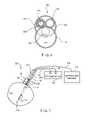
- FIG. 3is a perspective view of an ultrasound probe according to the present invention.
- FIG. 4is a perspective view of the ablation device of FIG. 1 , with an insertion device;
- FIG. 5is a perspective view of another embodiment of the ablation device according to the present invention.
- FIG. 6is a front view showing the ablation device of FIG. 5 ;
- FIG. 7is a perspective view of another embodiment of the ablation device according to the present invention.
- the present inventionmay be further understood with reference to the following description and the appended drawings, wherein like elements are referred to with the same reference numerals.
- the present inventionrelates to devices for treating tissue such as fibroids, tumors and other tissue masses by applying electric energy through electrodes inserted into a target tissue mass.
- the present inventionalso relates to devices used to ablate tissue to reshape an organ.
- energy delivery elements of the apparatus according to the present inventionare deployable from a single medical instrument.
- a single instrumentmay include two tined arrays or one tined array and one clamp which are placed on or within the target tissue mass to treat the target tissue.
- the instrumentmay include devices for grasping and holding in place the target tissue mass, minimizing the minimum number of incisions and medical personnel required to perform the procedure.
- the surgeonpunctures the target tissue mass with the device's needle and then deploys one or more RF tines into the tissue mass. An electric voltage is then applied to the tines to necrose the target tissue so that it is ablated. Lower levels of energy may be applied to achieve other therapeutic goals on the target tissue.
- these devicesare most effectively used on their own only by highly skilled individuals as it is difficult to properly place such devices within target tissue masses which tend to move when contacted. Even with skilled practitioners, multiple attempts may be required before a needle is correctly positioned.
- grasping devicessuch as tumor screws may be used in conjunction with these devices to immobilize and apply traction to the target tissue mass during insertion of the needle.
- thisrequires more time (or additional personnel) and may require multiple entry points through the skin, further increasing the complexity, time required for and discomfort associated with the procedure.
- the electrodesare not placed sufficiently close to a desired location within the target tissue mass, the targeted tissue may not be treated as desired as the range of RF ablation is limited.
- misplaced electrodesmay damage non targeted tissue in proximity to the target tissue mass.
- ultrasonic monitoring devicesmay be used to correctly place the electrodes in the target tissue, the quality of the images depends on the size of the probe's distal dome and there has been a trade-off between image quality and the invasiveness of the procedure.
- the size of ultrasound probes which have been employedhas been limited by the size of the working channels of the devices through which these probes have been inserted to the target tissue mass.
- FIG. 1shows an exemplary embodiment of a bipolar RF ablation system with an integrated ultrasound imaging probe, according to the invention.
- the systemis designed and configured so that it can be inserted into the patient's body through a small access port or channel, similar to a trocar.
- the systemcan be used to perform minimally invasive treatments, such as laparoscopically guided RF ablation of uterine fibroids.
- Other types of fibroids or abnormal tissuesmay also be treated with the exemplary system, particularly those formed in the lumens of hollow organs.
- target tissuesmay be reshaped by ablation or resection, and other therapeutic goals may be achieved by delivering selected amounts of energy to the target tissue.
- An RF ablation system 100comprises an RF portion having two cannulas 104 , 106 and an integrated imaging portion having an imaging device shaft 108 .
- the systemis configured to fit through a small port, through a trocar-like insertion device, or though the working channel of an endoscope to perform minimally invasive procedures.
- an exemplary systemmay fit through openings less than 10 mm in diameter and may more preferably fit through openings less than 5 mm in diameter.
- RF ablation cannulas 104 , 106are shown in a side by side configuration, extending along parallel axes.
- the cannulas 104 , 106are extendable side by side, independently from one another, so that the distal end of each cannula may be positioned at a different desired site within a target tissue mass 102 .
- a sharp distal end 114 of the RF cannula 104may be inserted and positioned at one end of the target tissue mass 102 just inside a surface thereof while the sharp distal end 116 of the RF cannula 106 is inserted further into the target tissue mass 102 to a location at the opposite end of the target tissue mass 102 .
- an ablation region of desired dimensionsmay be created by properly positioning the two distal ends 114 , 116 relative to one another.
- arrays of tines, or electrodesmay be deployed independently therefrom to better define the ablation region to be treated.
- a first array of tines 110may be deployed from an opening at the distal end 114 and a second array of tines 112 may be deployed from the second distal end 116 .
- the arrays 110 , 112are preferably shaped to define a size and shape of a region of the target tissue mass 102 to be ablated.
- Connections 118 , 120convey the RF energy from a generator 122 to each of the arrays 110 , 112 with the polarity of the energy provided to the array 110 being opposite that provided to the array 112 to create a bipolar ablation device.
- Connections 118 , 120may be electric wires, or other types of electric connections used conventionally in RF ablation probes.
- the configuration of the RF ablation systemmay be used to treat target tissues of different dimensions, simply by varying the relative positions of arrays 110 , 112 within the target tissue mass 102 .
- the systemalso allows for staged ablation of the target tissue mass 102 , thus enabling the operator to ablate a larger volume of tissue in one operation. For example, a first region of the target tissue mass 102 may be treated with the arrays 110 , 112 relatively close to one another. The arrays 110 , 112 may then be moved further apart, to treat a second, larger region of the target tissue mass 102 . The repositioning and treatment steps may be further repeated as needed to treat the entire target tissue mass 102 .
- the ultrasound visualization portion of the exemplary device shown in FIG. 1includes an ultrasound probe comprising a shaft 108 which is placed side by side with the two RF cannulas 104 , 106 .
- the RF cannulas 104 , 106can be moved longitudinally relative to the shaft 108 , but are attached thereto to form an integrated unit.
- the ultrasound probealso includes a dome 128 with a forward facing transducer 130 designed to be introduced into the body in the vicinity of the target tissue mass 102 .
- the shaft 108has a smaller diameter than the dome 128 , to reduce the cross sectional area of the device.
- the dome 128is mounted on the shaft 108 offset from an axis thereof. The assembly of the shaft 108 and the dome 128 can be rotated along the longitudinal axis, so that the dome 128 can be rotated toward and away from the RF cannulas 104 , 106 .
- the dome 128 containing the ultrasound sensor transducer 130is rotatable along the longitudinal axis of the shaft 108 . As depicted in greater detail in the front and perspective views shown in FIGS. 2 and 3 , the dome 128 rotates about the centerline axis x of the shaft 108 . Since the dome 128 is offset relative to the shaft 108 , and since the shaft 108 is generally aligned with the distal portions of cannulas 104 , 106 , it is possible to place the dome 128 in front of or beside the distal ends 114 , 116 thereof.
- FIG. 2shows the dome 128 in an operative position, to the side of the cannulas 104 , 106 .
- the dome 128is moved away from and does not interfere with the openings at the distal ends 114 , 116 so that deployment of the array of tines 110 , 112 from the cannulas 104 , 106 is unrestricted.
- the operative positionprovides the dome 128 with an unobstructed view of an operative field forward of the transducer 130 .
- the dome 128When the shaft 108 is rotated approximately 180 degrees in either direction from the orientation shown in FIG. 2 , the dome 128 is positioned in front of the openings 114 , 116 , in an insertion/removal configuration. This configuration facilitates passage of the dome 128 to and from the target tissue mass by reducing the profile of the entire device. When the dome 128 is placed in front of the cannulas 104 , 106 , the overall cross sectional area of the ablation system device 100 is reduced to a minimum.
- the cross sectional area of the device 100 in the insertion configurationmay be limited to the cross sectional area of the dome 128 with the width of the cannulas 104 , 106 and of the shaft 108 shadowed behind the width of the distal dome 128 .
- the size of the dome 128is the limiting factor which determines whether the RF ablation device 100 can pass through a particular insertion lumen.
- the profile dimensions of the cannulas 104 , 106 and of the shaft 108are all contained within the profile dimension of the distal dome 128 .
- the profile dimensioncorresponds to the maximum width of the device as seen from the front as the RF device is introduced into a lumen of an endoscope, trocar, or other insertion device.
- the width of the dome 128is at least as great as that of the rest of the device. The dome 128 can thus be selected to be as large as will fit through the insertion device.
- the dome 128is dimensioned to contain an ultrasound transducer capable of operating approximately in the 5 to 8 MHz frequency range. This frequency range is desirable because it provides higher resolution images of biological structures surrounding the transducer. Although ultrasonic transducers utilizing lower frequencies may obtain higher quality images these transducers also require larger dimension domes.
- An imaging station 126may be connected to the transducer 130 via an electric connection 124 which may include, for example, electric wires, a wireless connection, optical connections or other conventional means.
- the large dome 128is rotated in front of the cannulas 104 , 106 , so that the entire RF ablation system 100 can fit through a small passage, such as a working channel of an endoscope or of a trocar-like tube 150 .
- a small passagesuch as a working channel of an endoscope or of a trocar-like tube 150 .
- the dome 128is rotated away from the cannulas 104 , 106 to expose distal openings thereof so that the arrays of tines 110 , 112 may be deployed therefrom.
- FIG. 4shows an exemplary embodiment of the RF ablation system 100 in the deployed configuration, with arrays of tines 110 , 112 deployed and the dome 128 rotated away from cannulas 104 , 106 .
- the arrays of tines 110 , 112are retracted and the dome 128 is rotated back into the insertion/removal configuration and the device is withdrawn proximally through the tube 150 .
- FIGS. 5 and 6show an RF ablation system 200 according to a second exemplary embodiment of the invention.
- a visualization portion of the RF ablation system 200includes a shaft 108 and a dome 128 analogous to those described with reference to FIG. 1 .
- the dome 128is offset relative to the shaft 108 and can be rotated away from and toward two cannulas 202 , 204 between an insertion/removal configuration and a deployed configuration.
- the cannula 202is a dual lumen cannula including first and second lumens 220 , 222 through which arrays of tines 212 and 214 are deployed. As shown in FIG.
- the lumens 220 , 222are preferably concentric with each allowing passage of one of the two arrays of tines 212 , 214 .
- the lumens 220 , 222may be formed in a side-by-side or top-bottom arrangement.
- exit openings 208are formed at one or more selected locations along the length of the cannula 202 , so that the array of tines 212 may be deployed through the wall separating the lumens 220 , 222 at the selected locations relative to the location (e.g., opening 210 at the distal end of the cannula 202 ) from which the array of tines 214 is deployed.
- the system 200may further include a second cannula 204 through which a tissue anchoring device (e.g., a tissue screw 206 ) may be deployed.
- a tissue anchoring devicee.g., a tissue screw 206
- the cannula 204may be fixed or movable relative to the cannula 202 and the shaft 208 , depending on the requirements of the system.
- the cannula 204may be inserted through the tube 150 until its distal end is in a desired position adjacent to the target tissue mass 102 .
- the tissue anchoring element 206may then be deployed therefrom to retain the target tissue mass 102 in a desired position relative to the RF ablation system 200 (e.g., by grasping the target tissue mass 102 ) while the cannula 202 is inserted thereinto.
- the tubes forming the lumens 220 , 222may then be manipulated so that openings 208 , 210 are placed in desired positions relative to the target tissue mass 102 .
- the correct positioning of the arraysmay be ascertained using visualization provided by the ultrasound transducer 130 .
- the RF ablation proceduremay then take place as described above with visualization of the tissue providing feedback which the operator may use to determine when a desired degree of treatment of the target tissue mass 102 has been achieved.
- the cannulas 202 , 204are maintained in the withdrawn position, behind the dome 128 which is maintained in the insertion/removal configuration—i.e., with the dome 128 rotated to cover the cannulas 202 , 204 , minimizing the cross sectional profile of the device.
- the dome 128is rotated away from the cannulas 202 , 204 to the deployed configuration, the tissue anchoring device 206 is extended to grasp the target tissue mass 102 and the cannula 202 is extended into the target tissue mass 102 .
- the openings 208 , 210are located in desired positions within the target tissue mass 102 and the arrays of tines 212 , 214 are deployed for tissue ablation.
- the arrays of tines 212 , 214are retracted into the lumens 220 , 222 , respectively, the tissue grasping device 206 is withdrawn into the cannula 204 and the cannulas 202 and 204 are withdrawn into the tube 150 .
- the dome 128is rotated back into the insertion/removal configuration and the system 200 is withdrawn from the body via the tube 150 .
- FIG. 7shows another exemplary embodiment of an RF ablation system 300 according to the present invention.
- the ablation system 300is substantially similar to the prior embodiments in construction and operation except for the construction of the electrodes 210 , 212 .
- the system 300includes electrodes 210 , 212 formed as conductive bands around the first and second cannulas 104 , 106 , respectively.
- each of the electrodes 210 , 212may comprise one or more conductive bands which may be energized singularly or in any combinations desired.
Landscapes
- Health & Medical Sciences (AREA)
- Surgery (AREA)
- Engineering & Computer Science (AREA)
- Life Sciences & Earth Sciences (AREA)
- Biomedical Technology (AREA)
- Molecular Biology (AREA)
- Nuclear Medicine, Radiotherapy & Molecular Imaging (AREA)
- Plasma & Fusion (AREA)
- Physics & Mathematics (AREA)
- Heart & Thoracic Surgery (AREA)
- Medical Informatics (AREA)
- Otolaryngology (AREA)
- Animal Behavior & Ethology (AREA)
- General Health & Medical Sciences (AREA)
- Public Health (AREA)
- Veterinary Medicine (AREA)
- Surgical Instruments (AREA)
- Ultra Sonic Daignosis Equipment (AREA)
Abstract
Description
Claims (32)
Priority Applications (2)
| Application Number | Priority Date | Filing Date | Title |
|---|---|---|---|
| US11/053,344US7517346B2 (en) | 2005-02-08 | 2005-02-08 | Radio frequency ablation system with integrated ultrasound imaging |
| PCT/US2006/003879WO2006086233A1 (en) | 2005-02-08 | 2006-02-02 | Radio frequency ablation system with integrated ultrasound imaging |
Applications Claiming Priority (1)
| Application Number | Priority Date | Filing Date | Title |
|---|---|---|---|
| US11/053,344US7517346B2 (en) | 2005-02-08 | 2005-02-08 | Radio frequency ablation system with integrated ultrasound imaging |
Publications (2)
| Publication Number | Publication Date |
|---|---|
| US20060178665A1 US20060178665A1 (en) | 2006-08-10 |
| US7517346B2true US7517346B2 (en) | 2009-04-14 |
Family
ID=36481227
Family Applications (1)
| Application Number | Title | Priority Date | Filing Date |
|---|---|---|---|
| US11/053,344Expired - Fee RelatedUS7517346B2 (en) | 2005-02-08 | 2005-02-08 | Radio frequency ablation system with integrated ultrasound imaging |
Country Status (2)
| Country | Link |
|---|---|
| US (1) | US7517346B2 (en) |
| WO (1) | WO2006086233A1 (en) |
Cited By (33)
| Publication number | Priority date | Publication date | Assignee | Title |
|---|---|---|---|---|
| US20060189972A1 (en)* | 2005-02-02 | 2006-08-24 | Gynesonics, Inc. | Method and device for uterine fibroid treatment |
| US20070179380A1 (en)* | 2006-01-12 | 2007-08-02 | Gynesonics, Inc. | Interventional deployment and imaging system |
| US20070249939A1 (en)* | 2006-04-20 | 2007-10-25 | Gynesonics, Inc. | Rigid delivery systems having inclined ultrasound and curved needle |
| US20070249936A1 (en)* | 2006-04-20 | 2007-10-25 | Gynesonics, Inc. | Devices and methods for treatment of tissue |
| US20090287081A1 (en)* | 2008-04-29 | 2009-11-19 | Gynesonics , Inc | Submucosal fibroid ablation for the treatment of menorrhagia |
| US20100056926A1 (en)* | 2008-08-26 | 2010-03-04 | Gynesonics, Inc. | Ablation device with articulated imaging transducer |
| US8206300B2 (en) | 2008-08-26 | 2012-06-26 | Gynesonics, Inc. | Ablation device with articulated imaging transducer |
| US8262574B2 (en) | 2009-02-27 | 2012-09-11 | Gynesonics, Inc. | Needle and tine deployment mechanism |
| US20130079765A1 (en)* | 2010-01-29 | 2013-03-28 | Vivant Medical, Inc. | System and Method for Performing an Electrosurgical Procedure Using an Ablation Device with an Integrated Imaging Device |
| US20130178738A1 (en)* | 2012-01-10 | 2013-07-11 | Hologic, Inc. | System and Method for Tissue Ablation in a Body Cavity |
| US8514067B2 (en) | 2011-08-16 | 2013-08-20 | Elwha Llc | Systematic distillation of status data relating to regimen compliance |
| US9333031B2 (en) | 2013-04-08 | 2016-05-10 | Apama Medical, Inc. | Visualization inside an expandable medical device |
| US9610006B2 (en) | 2008-11-11 | 2017-04-04 | Shifamed Holdings, Llc | Minimally invasive visualization systems |
| US9655677B2 (en) | 2010-05-12 | 2017-05-23 | Shifamed Holdings, Llc | Ablation catheters including a balloon and electrodes |
| US9795442B2 (en) | 2008-11-11 | 2017-10-24 | Shifamed Holdings, Llc | Ablation catheters |
| US9861336B2 (en) | 2012-09-07 | 2018-01-09 | Gynesonics, Inc. | Methods and systems for controlled deployment of needle structures in tissue |
| WO2018089523A1 (en)* | 2016-11-11 | 2018-05-17 | Gynesonics, Inc. | Controlled treatment of tissue and dynamic interaction with, and comparison of, tissue and/or treatment data |
| US10058342B2 (en) | 2006-01-12 | 2018-08-28 | Gynesonics, Inc. | Devices and methods for treatment of tissue |
| US10098694B2 (en) | 2013-04-08 | 2018-10-16 | Apama Medical, Inc. | Tissue ablation and monitoring thereof |
| US10349824B2 (en) | 2013-04-08 | 2019-07-16 | Apama Medical, Inc. | Tissue mapping and visualization systems |
| US10595819B2 (en) | 2006-04-20 | 2020-03-24 | Gynesonics, Inc. | Ablation device with articulated imaging transducer |
| US10716618B2 (en) | 2010-05-21 | 2020-07-21 | Stratus Medical, LLC | Systems and methods for tissue ablation |
| US10736693B2 (en) | 2015-11-16 | 2020-08-11 | Apama Medical, Inc. | Energy delivery devices |
| US10736688B2 (en) | 2009-11-05 | 2020-08-11 | Stratus Medical, LLC | Methods and systems for spinal radio frequency neurotomy |
| US10925511B2 (en) | 2014-07-24 | 2021-02-23 | Cardiosolv Ablation Technologies, Inc. | System and method for cardiac ablation |
| US11096760B2 (en) | 2007-10-12 | 2021-08-24 | Gynesonics, Inc. | Methods and systems for controlled deployment of needles in tissue |
| US11219483B2 (en) | 2016-11-14 | 2022-01-11 | Gynesonics Inc. | Methods and systems for real-time planning and monitoring of ablation needle deployment in tissue |
| US11259825B2 (en) | 2006-01-12 | 2022-03-01 | Gynesonics, Inc. | Devices and methods for treatment of tissue |
| US11547471B2 (en) | 2019-03-27 | 2023-01-10 | Gyrus Acmi, Inc. | Device with loop electrodes for treatment of menorrhagia |
| US11612431B2 (en) | 2017-05-04 | 2023-03-28 | Gynesonics, Inc. | Methods for monitoring ablation progress with doppler ultrasound |
| US11944372B2 (en) | 2018-10-23 | 2024-04-02 | Boston Scientific Scimed, Inc. | Ablation probe system with center working channel |
| US12114919B2 (en) | 2018-10-24 | 2024-10-15 | Boston Scientific Scimed, Inc. | Movable electrodes for controlled irreversible electroporation ablative volumes |
| US12350097B2 (en) | 2020-01-07 | 2025-07-08 | Covidien Lp | Devices, systems, and methods for trans-vaginal, ultrasound-guided hysteroscopic surgical procedures |
Families Citing this family (16)
| Publication number | Priority date | Publication date | Assignee | Title |
|---|---|---|---|---|
| GB0504988D0 (en)* | 2005-03-10 | 2005-04-20 | Emcision Ltd | Device and method for the treatment of diseased tissue such as tumors |
| US20070161905A1 (en)* | 2006-01-12 | 2007-07-12 | Gynesonics, Inc. | Intrauterine ultrasound and method for use |
| EP2316505B1 (en) | 2006-03-14 | 2017-01-18 | University Of Southern California | Mems device for delivery of therapeutic agents |
| CN100459950C (en)* | 2006-11-30 | 2009-02-11 | 上海交通大学 | Image-guided water-cooled radiofrequency ablation tumor treatment all-in-one machine |
| WO2009086112A2 (en) | 2007-12-20 | 2009-07-09 | University Of Southern California | Apparatus and methods for delivering therapeutic agents |
| US8486278B2 (en) | 2008-05-08 | 2013-07-16 | Minipumps, Llc | Drug-delivery pumps and methods of manufacture |
| WO2013140353A2 (en)* | 2012-03-23 | 2013-09-26 | Koninklijke Philips N.V. | Imaging system for imaging a periodically moving object |
| WO2015058096A1 (en) | 2013-10-18 | 2015-04-23 | Ziva Medical, Inc. | Methods and systems for the treatment of polycystic ovary syndrome |
| ES2964948T3 (en) | 2015-03-31 | 2024-04-10 | May Health Us Inc | Methods and systems for the manipulation of ovarian tissues |
| JP2018075322A (en)* | 2016-11-12 | 2018-05-17 | 株式会社クレイツ | Ultrasonic/minute-current combined apparatus for skin care |
| US11564736B2 (en) | 2019-01-25 | 2023-01-31 | May Health Sas | Systems and methods for applying energy to ovarian tissue |
| US11602388B2 (en)* | 2019-08-21 | 2023-03-14 | Veran Medical Technologies, Inc. | Ablation monitoring system and method |
| DE102020124443A1 (en)* | 2019-09-26 | 2021-04-01 | Gyrus Acmi, Inc. D/B/A Olympus Surgical Technologies America | DEVICES, SYSTEMS AND METHODS FOR TRANSPORTING AIDS THROUGH A NARROW PASSAGE IN A BODY |
| CN114504378A (en)* | 2022-01-04 | 2022-05-17 | 南京航空航天大学 | Microwave ablation therapeutic apparatus integrating ultrasonic image guidance |
| US12369971B2 (en)* | 2022-07-15 | 2025-07-29 | Varian Medical Systems, Inc. | Systems and methods for imaging in connection with thermal ablation treatments |
| CN120360672B (en)* | 2025-06-27 | 2025-09-16 | 海杰亚(北京)医疗器械有限公司 | Transmission mechanism of ablation needle and ablation needle |
Citations (8)
| Publication number | Priority date | Publication date | Assignee | Title |
|---|---|---|---|---|
| WO1998044857A1 (en) | 1997-04-09 | 1998-10-15 | Goldberg S Nahum | Method and system for performing trans-rectal radiofrequency urethral enlargement |
| US5967984A (en) | 1995-06-30 | 1999-10-19 | Boston Scientific Corporation | Ultrasound imaging catheter with a cutting element |
| US6198974B1 (en)* | 1998-08-14 | 2001-03-06 | Cordis Webster, Inc. | Bi-directional steerable catheter |
| US20020002349A1 (en) | 1996-10-11 | 2002-01-03 | Transvascular, Inc. | Systems and methods for delivering drugs to selected locations within the body |
| US6692494B1 (en) | 1999-08-05 | 2004-02-17 | Broncus Technologies, Inc. | Methods and devices for creating collateral channels in the lungs |
| US6704605B2 (en)* | 2002-01-31 | 2004-03-09 | Cardiac Pacemakers, Inc. | Medical electrode assembly |
| US6764488B1 (en) | 1998-12-08 | 2004-07-20 | Vascular Control Systems, Inc. | Devices and methods for occlusion of the uterine arteries |
| US7195629B2 (en)* | 2000-09-15 | 2007-03-27 | Boston Scientific Scimed, Inc. | Methods and systems for focused bipolar tissue ablation |
- 2005
- 2005-02-08USUS11/053,344patent/US7517346B2/ennot_activeExpired - Fee Related
- 2006
- 2006-02-02WOPCT/US2006/003879patent/WO2006086233A1/enactiveApplication Filing
Patent Citations (8)
| Publication number | Priority date | Publication date | Assignee | Title |
|---|---|---|---|---|
| US5967984A (en) | 1995-06-30 | 1999-10-19 | Boston Scientific Corporation | Ultrasound imaging catheter with a cutting element |
| US20020002349A1 (en) | 1996-10-11 | 2002-01-03 | Transvascular, Inc. | Systems and methods for delivering drugs to selected locations within the body |
| WO1998044857A1 (en) | 1997-04-09 | 1998-10-15 | Goldberg S Nahum | Method and system for performing trans-rectal radiofrequency urethral enlargement |
| US6198974B1 (en)* | 1998-08-14 | 2001-03-06 | Cordis Webster, Inc. | Bi-directional steerable catheter |
| US6764488B1 (en) | 1998-12-08 | 2004-07-20 | Vascular Control Systems, Inc. | Devices and methods for occlusion of the uterine arteries |
| US6692494B1 (en) | 1999-08-05 | 2004-02-17 | Broncus Technologies, Inc. | Methods and devices for creating collateral channels in the lungs |
| US7195629B2 (en)* | 2000-09-15 | 2007-03-27 | Boston Scientific Scimed, Inc. | Methods and systems for focused bipolar tissue ablation |
| US6704605B2 (en)* | 2002-01-31 | 2004-03-09 | Cardiac Pacemakers, Inc. | Medical electrode assembly |
Cited By (78)
| Publication number | Priority date | Publication date | Assignee | Title |
|---|---|---|---|---|
| US20110087100A1 (en)* | 2005-02-02 | 2011-04-14 | Gynesonics, Inc. | Method and device for uterine fibroid treatment |
| US10182862B2 (en) | 2005-02-02 | 2019-01-22 | Gynesonics, Inc. | Method and device for uterine fibroid treatment |
| US11419668B2 (en) | 2005-02-02 | 2022-08-23 | Gynesonics, Inc. | Method and device for uterine fibroid treatment |
| US9987080B2 (en) | 2005-02-02 | 2018-06-05 | Gynesonics, Inc. | Method and device for uterine fibroid treatment |
| US9808310B2 (en) | 2005-02-02 | 2017-11-07 | Gynesonics, Inc. | Method and device for uterine fibroid treatment |
| US20060189972A1 (en)* | 2005-02-02 | 2006-08-24 | Gynesonics, Inc. | Method and device for uterine fibroid treatment |
| US11950837B2 (en) | 2005-02-02 | 2024-04-09 | Gynesonics, Inc. | Method and device for uterine fibroid treatment |
| US12414813B2 (en) | 2005-02-02 | 2025-09-16 | Gynesonics, Inc. | Method and device for uterine fibroid treatment |
| US7918795B2 (en) | 2005-02-02 | 2011-04-05 | Gynesonics, Inc. | Method and device for uterine fibroid treatment |
| US9357977B2 (en) | 2006-01-12 | 2016-06-07 | Gynesonics, Inc. | Interventional deployment and imaging system |
| US11259825B2 (en) | 2006-01-12 | 2022-03-01 | Gynesonics, Inc. | Devices and methods for treatment of tissue |
| US10058342B2 (en) | 2006-01-12 | 2018-08-28 | Gynesonics, Inc. | Devices and methods for treatment of tissue |
| US20070179380A1 (en)* | 2006-01-12 | 2007-08-02 | Gynesonics, Inc. | Interventional deployment and imaging system |
| US9517047B2 (en) | 2006-01-12 | 2016-12-13 | Gynesonics, Inc. | Interventional deployment and imaging system |
| US8506485B2 (en) | 2006-04-20 | 2013-08-13 | Gynesonics, Inc | Devices and methods for treatment of tissue |
| US7874986B2 (en) | 2006-04-20 | 2011-01-25 | Gynesonics, Inc. | Methods and devices for visualization and ablation of tissue |
| US10610197B2 (en) | 2006-04-20 | 2020-04-07 | Gynesonics, Inc. | Ablation device with articulated imaging transducer |
| US7815571B2 (en) | 2006-04-20 | 2010-10-19 | Gynesonics, Inc. | Rigid delivery systems having inclined ultrasound and needle |
| US20070249936A1 (en)* | 2006-04-20 | 2007-10-25 | Gynesonics, Inc. | Devices and methods for treatment of tissue |
| US20070249939A1 (en)* | 2006-04-20 | 2007-10-25 | Gynesonics, Inc. | Rigid delivery systems having inclined ultrasound and curved needle |
| US10595819B2 (en) | 2006-04-20 | 2020-03-24 | Gynesonics, Inc. | Ablation device with articulated imaging transducer |
| US12048583B2 (en) | 2006-04-20 | 2024-07-30 | Gynesonics, Inc. | Ablation device with articulated imaging transducer |
| US11826207B2 (en) | 2007-10-12 | 2023-11-28 | Gynesonics, Inc | Methods and systems for controlled deployment of needles in tissue |
| US11096761B2 (en) | 2007-10-12 | 2021-08-24 | Gynesonics, Inc. | Methods and systems for controlled deployment of needles in tissue |
| US11096760B2 (en) | 2007-10-12 | 2021-08-24 | Gynesonics, Inc. | Methods and systems for controlled deployment of needles in tissue |
| US11925512B2 (en) | 2007-10-12 | 2024-03-12 | Gynesonics, Inc. | Methods and systems for controlled deployment of needles in tissue |
| US20090287081A1 (en)* | 2008-04-29 | 2009-11-19 | Gynesonics , Inc | Submucosal fibroid ablation for the treatment of menorrhagia |
| US8206300B2 (en) | 2008-08-26 | 2012-06-26 | Gynesonics, Inc. | Ablation device with articulated imaging transducer |
| US20100056926A1 (en)* | 2008-08-26 | 2010-03-04 | Gynesonics, Inc. | Ablation device with articulated imaging transducer |
| US10251700B2 (en) | 2008-11-11 | 2019-04-09 | Shifamed Holdings, Llc | Ablation catheters |
| US9717557B2 (en) | 2008-11-11 | 2017-08-01 | Apama Medical, Inc. | Cardiac ablation catheters and methods of use thereof |
| US11744639B2 (en) | 2008-11-11 | 2023-09-05 | Shifamed Holdings Llc | Ablation catheters |
| US9795442B2 (en) | 2008-11-11 | 2017-10-24 | Shifamed Holdings, Llc | Ablation catheters |
| US9610006B2 (en) | 2008-11-11 | 2017-04-04 | Shifamed Holdings, Llc | Minimally invasive visualization systems |
| US10321951B2 (en) | 2009-02-27 | 2019-06-18 | Gynesonics, Inc. | Needle and tine deployment mechanism |
| US11564735B2 (en) | 2009-02-27 | 2023-01-31 | Gynesonics, Inc. | Needle and fine deployment mechanism |
| US11992258B2 (en) | 2009-02-27 | 2024-05-28 | Gynesonics, Inc. | Needle and tine deployment mechanism |
| US8262574B2 (en) | 2009-02-27 | 2012-09-11 | Gynesonics, Inc. | Needle and tine deployment mechanism |
| US11806070B2 (en) | 2009-11-05 | 2023-11-07 | Stratus Medical, LLC | Methods and systems for spinal radio frequency neurotomy |
| US10925664B2 (en) | 2009-11-05 | 2021-02-23 | Stratus Medical, LLC | Methods for radio frequency neurotomy |
| US10736688B2 (en) | 2009-11-05 | 2020-08-11 | Stratus Medical, LLC | Methods and systems for spinal radio frequency neurotomy |
| US9713497B2 (en)* | 2010-01-29 | 2017-07-25 | Covidien Lp | System and method for performing an electrosurgical procedure using an ablation device with an integrated imaging device |
| US9308045B2 (en)* | 2010-01-29 | 2016-04-12 | Covidien Lp | System and method for performing an electrosurgical procedure using an ablation device with an integrated imaging device |
| US20130079765A1 (en)* | 2010-01-29 | 2013-03-28 | Vivant Medical, Inc. | System and Method for Performing an Electrosurgical Procedure Using an Ablation Device with an Integrated Imaging Device |
| US9655677B2 (en) | 2010-05-12 | 2017-05-23 | Shifamed Holdings, Llc | Ablation catheters including a balloon and electrodes |
| US10716618B2 (en) | 2010-05-21 | 2020-07-21 | Stratus Medical, LLC | Systems and methods for tissue ablation |
| US10966782B2 (en) | 2010-05-21 | 2021-04-06 | Stratus Medical, LLC | Needles and systems for radiofrequency neurotomy |
| US8816814B2 (en) | 2011-08-16 | 2014-08-26 | Elwha Llc | Systematic distillation of status data responsive to whether or not a wireless signal has been received and relating to regimen compliance |
| US9770189B2 (en) | 2011-08-16 | 2017-09-26 | Elwha Llc | Systematic distillation of status data relating to regimen compliance |
| US8514067B2 (en) | 2011-08-16 | 2013-08-20 | Elwha Llc | Systematic distillation of status data relating to regimen compliance |
| US8599009B2 (en) | 2011-08-16 | 2013-12-03 | Elwha Llc | Systematic distillation of status data relating to regimen compliance |
| US8723640B2 (en) | 2011-08-16 | 2014-05-13 | Elwha Llc | Distillation of status data relating to regimen compliance responsive to the presence and absence of wireless signals relating to one or more threshold frequencies |
| US20130178738A1 (en)* | 2012-01-10 | 2013-07-11 | Hologic, Inc. | System and Method for Tissue Ablation in a Body Cavity |
| US8814796B2 (en)* | 2012-01-10 | 2014-08-26 | Hologic, Inc. | System and method for tissue ablation in a body cavity |
| US9861336B2 (en) | 2012-09-07 | 2018-01-09 | Gynesonics, Inc. | Methods and systems for controlled deployment of needle structures in tissue |
| US11890134B2 (en) | 2012-09-07 | 2024-02-06 | Gynesonics, Inc. | Methods and systems for controlled deployment of needle structures in tissue |
| US12383224B2 (en) | 2012-09-07 | 2025-08-12 | Gynesonics, Inc. | Methods and systems for controlled deployment of needle structures in tissue |
| US10856838B2 (en) | 2012-09-07 | 2020-12-08 | Gynesonics, Inc. | Methods and systems for controlled deployment of needle structures in tissue |
| US11583243B2 (en) | 2012-09-07 | 2023-02-21 | Gynesonics, Inc. | Methods and systems for controlled deployment of needle structures in tissue |
| US11439298B2 (en) | 2013-04-08 | 2022-09-13 | Boston Scientific Scimed, Inc. | Surface mapping and visualizing ablation system |
| US10349824B2 (en) | 2013-04-08 | 2019-07-16 | Apama Medical, Inc. | Tissue mapping and visualization systems |
| US11684415B2 (en) | 2013-04-08 | 2023-06-27 | Boston Scientific Scimed, Inc. | Tissue ablation and monitoring thereof |
| US10098694B2 (en) | 2013-04-08 | 2018-10-16 | Apama Medical, Inc. | Tissue ablation and monitoring thereof |
| US9333031B2 (en) | 2013-04-08 | 2016-05-10 | Apama Medical, Inc. | Visualization inside an expandable medical device |
| US10925511B2 (en) | 2014-07-24 | 2021-02-23 | Cardiosolv Ablation Technologies, Inc. | System and method for cardiac ablation |
| US11839459B2 (en) | 2014-07-24 | 2023-12-12 | Cardiosolv Ablation Technologies, Inc. | System and method for cardiac ablation |
| US10736693B2 (en) | 2015-11-16 | 2020-08-11 | Apama Medical, Inc. | Energy delivery devices |
| US11419682B2 (en) | 2016-11-11 | 2022-08-23 | Gynesonics, Inc. | Controlled treatment of tissue and dynamic interaction with, and comparison of, tissue and/or treatment data |
| WO2018089523A1 (en)* | 2016-11-11 | 2018-05-17 | Gynesonics, Inc. | Controlled treatment of tissue and dynamic interaction with, and comparison of, tissue and/or treatment data |
| US12239382B2 (en) | 2016-11-11 | 2025-03-04 | Gynesonics, Inc. | Controlled treatment of tissue and dynamic interaction with, and comparison of, tissue and/or treatment data |
| US10993770B2 (en) | 2016-11-11 | 2021-05-04 | Gynesonics, Inc. | Controlled treatment of tissue and dynamic interaction with, and comparison of, tissue and/or treatment data |
| US11219483B2 (en) | 2016-11-14 | 2022-01-11 | Gynesonics Inc. | Methods and systems for real-time planning and monitoring of ablation needle deployment in tissue |
| US11612431B2 (en) | 2017-05-04 | 2023-03-28 | Gynesonics, Inc. | Methods for monitoring ablation progress with doppler ultrasound |
| US12408977B2 (en) | 2017-05-04 | 2025-09-09 | Gynesonics, Inc. | Methods for monitoring ablation progress with doppler ultrasound |
| US11944372B2 (en) | 2018-10-23 | 2024-04-02 | Boston Scientific Scimed, Inc. | Ablation probe system with center working channel |
| US12114919B2 (en) | 2018-10-24 | 2024-10-15 | Boston Scientific Scimed, Inc. | Movable electrodes for controlled irreversible electroporation ablative volumes |
| US11547471B2 (en) | 2019-03-27 | 2023-01-10 | Gyrus Acmi, Inc. | Device with loop electrodes for treatment of menorrhagia |
| US12350097B2 (en) | 2020-01-07 | 2025-07-08 | Covidien Lp | Devices, systems, and methods for trans-vaginal, ultrasound-guided hysteroscopic surgical procedures |
Also Published As
| Publication number | Publication date |
|---|---|
| US20060178665A1 (en) | 2006-08-10 |
| WO2006086233A1 (en) | 2006-08-17 |
Similar Documents
| Publication | Publication Date | Title |
|---|---|---|
| US7517346B2 (en) | Radio frequency ablation system with integrated ultrasound imaging | |
| US12329412B2 (en) | Systems for accessing nerves within bone | |
| US20040254572A1 (en) | Self anchoring radio frequency ablation array | |
| US10779882B2 (en) | Electrical ablation devices | |
| US8506485B2 (en) | Devices and methods for treatment of tissue | |
| US10058342B2 (en) | Devices and methods for treatment of tissue | |
| US20080200911A1 (en) | Electrical ablation apparatus, system, and method | |
| WO2011161474A1 (en) | Enhanced ablation apparatus | |
| US11259825B2 (en) | Devices and methods for treatment of tissue | |
| GB2590139A (en) | Apparatuses, systems, and methods for conveying implements through a narrow passage in a body | |
| HK40012611A (en) | Systems and for navigating an instrument through bone |
Legal Events
| Date | Code | Title | Description |
|---|---|---|---|
| AS | Assignment | Owner name:BOSTON SCIENTIFIC SCIMED, INC., MINNESOTA Free format text:CHANGE OF NAME;ASSIGNOR:SCIMED LIFE SYSTEMS, INC.;REEL/FRAME:016270/0405 Effective date:20041222 Owner name:SCIMED LIFE SYSTEMS, INC., MINNESOTA Free format text:ASSIGNMENT OF ASSIGNORS INTEREST;ASSIGNORS:SLOAN, TODD;OSTROVSKY, ISAAC;MCINTYRE, JON T.;REEL/FRAME:016270/0757;SIGNING DATES FROM 20050113 TO 20050128 | |
| FEPP | Fee payment procedure | Free format text:PAYOR NUMBER ASSIGNED (ORIGINAL EVENT CODE: ASPN); ENTITY STATUS OF PATENT OWNER: LARGE ENTITY | |
| STCF | Information on status: patent grant | Free format text:PATENTED CASE | |
| FPAY | Fee payment | Year of fee payment:4 | |
| FPAY | Fee payment | Year of fee payment:8 | |
| FEPP | Fee payment procedure | Free format text:MAINTENANCE FEE REMINDER MAILED (ORIGINAL EVENT CODE: REM.); ENTITY STATUS OF PATENT OWNER: LARGE ENTITY | |
| LAPS | Lapse for failure to pay maintenance fees | Free format text:PATENT EXPIRED FOR FAILURE TO PAY MAINTENANCE FEES (ORIGINAL EVENT CODE: EXP.); ENTITY STATUS OF PATENT OWNER: LARGE ENTITY | |
| STCH | Information on status: patent discontinuation | Free format text:PATENT EXPIRED DUE TO NONPAYMENT OF MAINTENANCE FEES UNDER 37 CFR 1.362 | |
| FP | Lapsed due to failure to pay maintenance fee | Effective date:20210414 |