US7517303B2 - Upper body exercise and flywheel enhanced dual deck treadmills - Google Patents
Upper body exercise and flywheel enhanced dual deck treadmillsDownload PDFInfo
- Publication number
- US7517303B2 US7517303B2US11/065,746US6574605AUS7517303B2US 7517303 B2US7517303 B2US 7517303B2US 6574605 AUS6574605 AUS 6574605AUS 7517303 B2US7517303 B2US 7517303B2
- Authority
- US
- United States
- Prior art keywords
- treadle
- exercise device
- exercise
- assembly
- user
- Prior art date
- Legal status (The legal status is an assumption and is not a legal conclusion. Google has not performed a legal analysis and makes no representation as to the accuracy of the status listed.)
- Expired - Fee Related
Links
- 230000009977dual effectEffects0.000titledescription16
- 230000035939shockEffects0.000description28
- 230000000712assemblyEffects0.000description25
- 238000000429assemblyMethods0.000description25
- 210000002683footAnatomy0.000description21
- 210000002414legAnatomy0.000description14
- 238000000034methodMethods0.000description8
- 230000008878couplingEffects0.000description7
- 238000010168coupling processMethods0.000description7
- 238000005859coupling reactionMethods0.000description7
- 235000014676Phragmites communisNutrition0.000description6
- 230000008901benefitEffects0.000description6
- 239000012530fluidSubstances0.000description6
- 238000005266castingMethods0.000description5
- 230000009194climbingEffects0.000description5
- 230000007407health benefitEffects0.000description4
- 230000001681protective effectEffects0.000description4
- NJPPVKZQTLUDBO-UHFFFAOYSA-NnovaluronChemical compoundC1=C(Cl)C(OC(F)(F)C(OC(F)(F)F)F)=CC=C1NC(=O)NC(=O)C1=C(F)C=CC=C1FNJPPVKZQTLUDBO-UHFFFAOYSA-N0.000description3
- 238000005516engineering processMethods0.000description2
- 210000003127kneeAnatomy0.000description2
- 238000003825pressingMethods0.000description2
- 210000001015abdomenAnatomy0.000description1
- 230000009471actionEffects0.000description1
- WYTGDNHDOZPMIW-RCBQFDQVSA-NalstonineNatural productsC1=CC2=C3C=CC=CC3=NC2=C2N1C[C@H]1[C@H](C)OC=C(C(=O)OC)[C@H]1C2WYTGDNHDOZPMIW-RCBQFDQVSA-N0.000description1
- 210000003423ankleAnatomy0.000description1
- 230000010036cardiovascular benefitEffects0.000description1
- 230000008859changeEffects0.000description1
- 239000011248coating agentSubstances0.000description1
- 238000000576coating methodMethods0.000description1
- 230000006835compressionEffects0.000description1
- 238000007906compressionMethods0.000description1
- 230000002526effect on cardiovascular systemEffects0.000description1
- 238000010894electron beam technologyMethods0.000description1
- 230000002708enhancing effectEffects0.000description1
- 239000000835fiberSubstances0.000description1
- 239000002783friction materialSubstances0.000description1
- 238000010348incorporationMethods0.000description1
- 230000003993interactionEffects0.000description1
- 238000004519manufacturing processMethods0.000description1
- 239000000463materialSubstances0.000description1
- 210000003205muscleAnatomy0.000description1
- 230000010355oscillationEffects0.000description1
- 239000003973paintSubstances0.000description1
- 229920000728polyesterPolymers0.000description1
- 239000002861polymer materialSubstances0.000description1
- 229920001296polysiloxanePolymers0.000description1
- 230000000284resting effectEffects0.000description1
- 238000005096rolling processMethods0.000description1
- 239000004576sandSubstances0.000description1
- 239000007787solidSubstances0.000description1
- 239000000725suspensionSubstances0.000description1
- 230000001360synchronised effectEffects0.000description1
- 230000007704transitionEffects0.000description1
Images


Classifications
- A—HUMAN NECESSITIES
- A63—SPORTS; GAMES; AMUSEMENTS
- A63B—APPARATUS FOR PHYSICAL TRAINING, GYMNASTICS, SWIMMING, CLIMBING, OR FENCING; BALL GAMES; TRAINING EQUIPMENT
- A63B22/00—Exercising apparatus specially adapted for conditioning the cardio-vascular system, for training agility or co-ordination of movements
- A63B22/02—Exercising apparatus specially adapted for conditioning the cardio-vascular system, for training agility or co-ordination of movements with movable endless bands, e.g. treadmills
- A63B22/0235—Exercising apparatus specially adapted for conditioning the cardio-vascular system, for training agility or co-ordination of movements with movable endless bands, e.g. treadmills driven by a motor
- A—HUMAN NECESSITIES
- A63—SPORTS; GAMES; AMUSEMENTS
- A63B—APPARATUS FOR PHYSICAL TRAINING, GYMNASTICS, SWIMMING, CLIMBING, OR FENCING; BALL GAMES; TRAINING EQUIPMENT
- A63B21/00—Exercising apparatus for developing or strengthening the muscles or joints of the body by working against a counterforce, with or without measuring devices
- A63B21/15—Arrangements for force transmissions
- A63B21/151—Using flexible elements for reciprocating movements, e.g. ropes or chains
- A63B21/154—Using flexible elements for reciprocating movements, e.g. ropes or chains using special pulley-assemblies
- A—HUMAN NECESSITIES
- A63—SPORTS; GAMES; AMUSEMENTS
- A63B—APPARATUS FOR PHYSICAL TRAINING, GYMNASTICS, SWIMMING, CLIMBING, OR FENCING; BALL GAMES; TRAINING EQUIPMENT
- A63B21/00—Exercising apparatus for developing or strengthening the muscles or joints of the body by working against a counterforce, with or without measuring devices
- A63B21/40—Interfaces with the user related to strength training; Details thereof
- A63B21/4027—Specific exercise interfaces
- A63B21/4033—Handles, pedals, bars or platforms
- A63B21/4035—Handles, pedals, bars or platforms for operation by hand
- A—HUMAN NECESSITIES
- A63—SPORTS; GAMES; AMUSEMENTS
- A63B—APPARATUS FOR PHYSICAL TRAINING, GYMNASTICS, SWIMMING, CLIMBING, OR FENCING; BALL GAMES; TRAINING EQUIPMENT
- A63B22/00—Exercising apparatus specially adapted for conditioning the cardio-vascular system, for training agility or co-ordination of movements
- A63B22/0002—Exercising apparatus specially adapted for conditioning the cardio-vascular system, for training agility or co-ordination of movements involving an exercising of arms
- A63B22/0005—Exercising apparatus specially adapted for conditioning the cardio-vascular system, for training agility or co-ordination of movements involving an exercising of arms with particular movement of the arms provided by handles moving otherwise than pivoting about a horizontal axis parallel to the body-symmetrical-plane
- A—HUMAN NECESSITIES
- A63—SPORTS; GAMES; AMUSEMENTS
- A63B—APPARATUS FOR PHYSICAL TRAINING, GYMNASTICS, SWIMMING, CLIMBING, OR FENCING; BALL GAMES; TRAINING EQUIPMENT
- A63B22/00—Exercising apparatus specially adapted for conditioning the cardio-vascular system, for training agility or co-ordination of movements
- A63B22/0002—Exercising apparatus specially adapted for conditioning the cardio-vascular system, for training agility or co-ordination of movements involving an exercising of arms
- A63B22/001—Exercising apparatus specially adapted for conditioning the cardio-vascular system, for training agility or co-ordination of movements involving an exercising of arms by simultaneously exercising arms and legs, e.g. diagonally in anti-phase
- A63B22/0012—Exercising apparatus specially adapted for conditioning the cardio-vascular system, for training agility or co-ordination of movements involving an exercising of arms by simultaneously exercising arms and legs, e.g. diagonally in anti-phase the exercises for arms and legs being functionally independent
- A—HUMAN NECESSITIES
- A63—SPORTS; GAMES; AMUSEMENTS
- A63B—APPARATUS FOR PHYSICAL TRAINING, GYMNASTICS, SWIMMING, CLIMBING, OR FENCING; BALL GAMES; TRAINING EQUIPMENT
- A63B22/00—Exercising apparatus specially adapted for conditioning the cardio-vascular system, for training agility or co-ordination of movements
- A63B22/0048—Exercising apparatus specially adapted for conditioning the cardio-vascular system, for training agility or co-ordination of movements with cantilevered support elements pivoting about an axis
- A63B22/0056—Exercising apparatus specially adapted for conditioning the cardio-vascular system, for training agility or co-ordination of movements with cantilevered support elements pivoting about an axis the pivoting movement being in a vertical plane, e.g. steppers with a horizontal axis
- A—HUMAN NECESSITIES
- A63—SPORTS; GAMES; AMUSEMENTS
- A63B—APPARATUS FOR PHYSICAL TRAINING, GYMNASTICS, SWIMMING, CLIMBING, OR FENCING; BALL GAMES; TRAINING EQUIPMENT
- A63B22/00—Exercising apparatus specially adapted for conditioning the cardio-vascular system, for training agility or co-ordination of movements
- A63B22/02—Exercising apparatus specially adapted for conditioning the cardio-vascular system, for training agility or co-ordination of movements with movable endless bands, e.g. treadmills
- A63B22/0235—Exercising apparatus specially adapted for conditioning the cardio-vascular system, for training agility or co-ordination of movements with movable endless bands, e.g. treadmills driven by a motor
- A63B22/0242—Exercising apparatus specially adapted for conditioning the cardio-vascular system, for training agility or co-ordination of movements with movable endless bands, e.g. treadmills driven by a motor with speed variation
- A63B22/025—Exercising apparatus specially adapted for conditioning the cardio-vascular system, for training agility or co-ordination of movements with movable endless bands, e.g. treadmills driven by a motor with speed variation electrically, e.g. D.C. motors with variable speed control
- A—HUMAN NECESSITIES
- A63—SPORTS; GAMES; AMUSEMENTS
- A63B—APPARATUS FOR PHYSICAL TRAINING, GYMNASTICS, SWIMMING, CLIMBING, OR FENCING; BALL GAMES; TRAINING EQUIPMENT
- A63B22/00—Exercising apparatus specially adapted for conditioning the cardio-vascular system, for training agility or co-ordination of movements
- A63B22/02—Exercising apparatus specially adapted for conditioning the cardio-vascular system, for training agility or co-ordination of movements with movable endless bands, e.g. treadmills
- A63B22/0292—Exercising apparatus specially adapted for conditioning the cardio-vascular system, for training agility or co-ordination of movements with movable endless bands, e.g. treadmills separate for each leg, e.g. dual deck
- A—HUMAN NECESSITIES
- A63—SPORTS; GAMES; AMUSEMENTS
- A63B—APPARATUS FOR PHYSICAL TRAINING, GYMNASTICS, SWIMMING, CLIMBING, OR FENCING; BALL GAMES; TRAINING EQUIPMENT
- A63B23/00—Exercising apparatus specially adapted for particular parts of the body
- A63B23/035—Exercising apparatus specially adapted for particular parts of the body for limbs, i.e. upper or lower limbs, e.g. simultaneously
- A63B23/03516—For both arms together or both legs together; Aspects related to the co-ordination between right and left side limbs of a user
- A63B23/03533—With separate means driven by each limb, i.e. performing different movements
- A63B23/03541—Moving independently from each other
- A—HUMAN NECESSITIES
- A63—SPORTS; GAMES; AMUSEMENTS
- A63B—APPARATUS FOR PHYSICAL TRAINING, GYMNASTICS, SWIMMING, CLIMBING, OR FENCING; BALL GAMES; TRAINING EQUIPMENT
- A63B23/00—Exercising apparatus specially adapted for particular parts of the body
- A63B23/035—Exercising apparatus specially adapted for particular parts of the body for limbs, i.e. upper or lower limbs, e.g. simultaneously
- A63B23/03575—Apparatus used for exercising upper and lower limbs simultaneously
- A63B23/03583—Upper and lower limbs acting simultaneously on the same operating rigid member
- A—HUMAN NECESSITIES
- A63—SPORTS; GAMES; AMUSEMENTS
- A63B—APPARATUS FOR PHYSICAL TRAINING, GYMNASTICS, SWIMMING, CLIMBING, OR FENCING; BALL GAMES; TRAINING EQUIPMENT
- A63B23/00—Exercising apparatus specially adapted for particular parts of the body
- A63B23/035—Exercising apparatus specially adapted for particular parts of the body for limbs, i.e. upper or lower limbs, e.g. simultaneously
- A63B23/03575—Apparatus used for exercising upper and lower limbs simultaneously
- A63B23/03591—Upper and lower limb moving in phase, i.e. right foot moving in the same direction as the right hand
- A—HUMAN NECESSITIES
- A63—SPORTS; GAMES; AMUSEMENTS
- A63B—APPARATUS FOR PHYSICAL TRAINING, GYMNASTICS, SWIMMING, CLIMBING, OR FENCING; BALL GAMES; TRAINING EQUIPMENT
- A63B23/00—Exercising apparatus specially adapted for particular parts of the body
- A63B23/035—Exercising apparatus specially adapted for particular parts of the body for limbs, i.e. upper or lower limbs, e.g. simultaneously
- A63B23/12—Exercising apparatus specially adapted for particular parts of the body for limbs, i.e. upper or lower limbs, e.g. simultaneously for upper limbs or related muscles, e.g. chest, upper back or shoulder muscles
- A—HUMAN NECESSITIES
- A63—SPORTS; GAMES; AMUSEMENTS
- A63B—APPARATUS FOR PHYSICAL TRAINING, GYMNASTICS, SWIMMING, CLIMBING, OR FENCING; BALL GAMES; TRAINING EQUIPMENT
- A63B22/00—Exercising apparatus specially adapted for conditioning the cardio-vascular system, for training agility or co-ordination of movements
- A63B22/0025—Particular aspects relating to the orientation of movement paths of the limbs relative to the body; Relative relationship between the movements of the limbs
- A63B2022/0041—Particular aspects relating to the orientation of movement paths of the limbs relative to the body; Relative relationship between the movements of the limbs one hand moving independently from the other hand, i.e. there is no link between the movements of the hands
- A—HUMAN NECESSITIES
- A63—SPORTS; GAMES; AMUSEMENTS
- A63B—APPARATUS FOR PHYSICAL TRAINING, GYMNASTICS, SWIMMING, CLIMBING, OR FENCING; BALL GAMES; TRAINING EQUIPMENT
- A63B22/00—Exercising apparatus specially adapted for conditioning the cardio-vascular system, for training agility or co-ordination of movements
- A63B22/06—Exercising apparatus specially adapted for conditioning the cardio-vascular system, for training agility or co-ordination of movements with support elements performing a rotating cycling movement, i.e. a closed path movement
- A63B22/0664—Exercising apparatus specially adapted for conditioning the cardio-vascular system, for training agility or co-ordination of movements with support elements performing a rotating cycling movement, i.e. a closed path movement performing an elliptic movement
- A63B2022/067—Exercising apparatus specially adapted for conditioning the cardio-vascular system, for training agility or co-ordination of movements with support elements performing a rotating cycling movement, i.e. a closed path movement performing an elliptic movement with crank and handles being on opposite sides of the exercising apparatus with respect to the frontal body-plane of the user, e.g. the crank is behind and handles are in front of the user
- A—HUMAN NECESSITIES
- A63—SPORTS; GAMES; AMUSEMENTS
- A63B—APPARATUS FOR PHYSICAL TRAINING, GYMNASTICS, SWIMMING, CLIMBING, OR FENCING; BALL GAMES; TRAINING EQUIPMENT
- A63B21/00—Exercising apparatus for developing or strengthening the muscles or joints of the body by working against a counterforce, with or without measuring devices
- A63B21/02—Exercising apparatus for developing or strengthening the muscles or joints of the body by working against a counterforce, with or without measuring devices using resilient force-resisters
- A63B21/026—Bars; Tubes; Leaf springs
- A—HUMAN NECESSITIES
- A63—SPORTS; GAMES; AMUSEMENTS
- A63B—APPARATUS FOR PHYSICAL TRAINING, GYMNASTICS, SWIMMING, CLIMBING, OR FENCING; BALL GAMES; TRAINING EQUIPMENT
- A63B21/00—Exercising apparatus for developing or strengthening the muscles or joints of the body by working against a counterforce, with or without measuring devices
- A63B21/02—Exercising apparatus for developing or strengthening the muscles or joints of the body by working against a counterforce, with or without measuring devices using resilient force-resisters
- A63B21/045—Exercising apparatus for developing or strengthening the muscles or joints of the body by working against a counterforce, with or without measuring devices using resilient force-resisters having torsion or bending or flexion element
- A—HUMAN NECESSITIES
- A63—SPORTS; GAMES; AMUSEMENTS
- A63B—APPARATUS FOR PHYSICAL TRAINING, GYMNASTICS, SWIMMING, CLIMBING, OR FENCING; BALL GAMES; TRAINING EQUIPMENT
- A63B21/00—Exercising apparatus for developing or strengthening the muscles or joints of the body by working against a counterforce, with or without measuring devices
- A63B21/22—Resisting devices with rotary bodies
- A63B21/225—Resisting devices with rotary bodies with flywheels
- A—HUMAN NECESSITIES
- A63—SPORTS; GAMES; AMUSEMENTS
- A63B—APPARATUS FOR PHYSICAL TRAINING, GYMNASTICS, SWIMMING, CLIMBING, OR FENCING; BALL GAMES; TRAINING EQUIPMENT
- A63B22/00—Exercising apparatus specially adapted for conditioning the cardio-vascular system, for training agility or co-ordination of movements
- A63B22/02—Exercising apparatus specially adapted for conditioning the cardio-vascular system, for training agility or co-ordination of movements with movable endless bands, e.g. treadmills
- A63B22/0285—Physical characteristics of the belt, e.g. material, surface, indicia
- A—HUMAN NECESSITIES
- A63—SPORTS; GAMES; AMUSEMENTS
- A63B—APPARATUS FOR PHYSICAL TRAINING, GYMNASTICS, SWIMMING, CLIMBING, OR FENCING; BALL GAMES; TRAINING EQUIPMENT
- A63B22/00—Exercising apparatus specially adapted for conditioning the cardio-vascular system, for training agility or co-ordination of movements
- A63B22/06—Exercising apparatus specially adapted for conditioning the cardio-vascular system, for training agility or co-ordination of movements with support elements performing a rotating cycling movement, i.e. a closed path movement
- A63B22/0664—Exercising apparatus specially adapted for conditioning the cardio-vascular system, for training agility or co-ordination of movements with support elements performing a rotating cycling movement, i.e. a closed path movement performing an elliptic movement
- A—HUMAN NECESSITIES
- A63—SPORTS; GAMES; AMUSEMENTS
- A63B—APPARATUS FOR PHYSICAL TRAINING, GYMNASTICS, SWIMMING, CLIMBING, OR FENCING; BALL GAMES; TRAINING EQUIPMENT
- A63B23/00—Exercising apparatus specially adapted for particular parts of the body
- A63B23/035—Exercising apparatus specially adapted for particular parts of the body for limbs, i.e. upper or lower limbs, e.g. simultaneously
- A63B23/03516—For both arms together or both legs together; Aspects related to the co-ordination between right and left side limbs of a user
- A63B23/03533—With separate means driven by each limb, i.e. performing different movements
- A—HUMAN NECESSITIES
- A63—SPORTS; GAMES; AMUSEMENTS
- A63B—APPARATUS FOR PHYSICAL TRAINING, GYMNASTICS, SWIMMING, CLIMBING, OR FENCING; BALL GAMES; TRAINING EQUIPMENT
- A63B23/00—Exercising apparatus specially adapted for particular parts of the body
- A63B23/035—Exercising apparatus specially adapted for particular parts of the body for limbs, i.e. upper or lower limbs, e.g. simultaneously
- A63B23/12—Exercising apparatus specially adapted for particular parts of the body for limbs, i.e. upper or lower limbs, e.g. simultaneously for upper limbs or related muscles, e.g. chest, upper back or shoulder muscles
- A63B23/1209—Involving a bending of elbow and shoulder joints simultaneously
Definitions
- the present applicationis a non-provisional utility application claiming priority to U.S. Provisional Patent Application No. 60/548,787 titled “Hydraulic Resistance, Arm Exercise and Non-Motorized Dual Deck Treadmills” filed Feb. 26, 2004, U.S. Provisional Patent Application No. 60/548,265 titled “Exercise Device with Treadles (Commercial)” filed on Feb. 26, 2004, U.S. Provisional Patent Application No. 60/548,786 titled “Control System and Method for an Exercise Apparatus” filed on Feb. 26, 2004, and U.S. Provisional Patent Application No. 60/548,811 titled “Dual Treadmill Exercise Device having a Single Rear Roller” filed on Feb. 26, 2004, all of which are hereby incorporated by reference herein.
- the present inventiongenerally involves the field of exercise devices, and more particularly involves an exercise device including interconnected treadles with moving surfaces provided thereon, and arm exercise and non-motorized embodiments thereof.
- a conventional treadmilltypically includes a continuous belt providing a moving surface that a user may walk, jog, or run on.
- a conventional stair climbing machinetypically includes a pair of links adapted to pivot up and down providing a pair of surfaces or pedals that a user may stand on and press up and down to simulate walking up a flight of stairs.
- Various embodiments and aspects of the present inventioninvolve an exercise machine that provides side-by-side moving surfaces that are pivotally supported at one end and adapted to pivot up and down at an opposite end.
- two pivotal moving surfacesare provided in a manner that provides some or all of the exercise benefits of using a treadmill with some or all of the exercise benefits of using a stair climbing machine.
- An exercise machine conforming to aspects of the present inventionprovides additional health benefits that are not recognized by a treadmill or a stair climbing machine alone.
- an exercise devicein one aspect of the present invention, includes a frame structure; a first treadle assembly supporting a first moving surface, a second treadle assembly supporting a second moving surface, and an upper body exercise assembly operably associated with the exercise device.
- the first treadle assemblyis pivotally coupled with the frame structure, and the second treadle assembly is pivotally coupled with the frame structure.
- an exercise devicein another form, includes a frame structure, a first treadle assembly having a first endless belt in rotatable engagement with a first roller, a second treadle assembly having a second endless belt in rotatable engagement with a second roller, and a flywheel operably coupled with the first endless belt and the second endless belt.
- FIG. 1is an isometric view of one embodiment of an exercise device, in accordance with aspects of the present invention
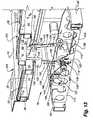
- FIG. 2is an isometric view of the exercise device shown in FIG. 1 with decorative and protective side panels removed to better illustrate various components of the exercise device;
- FIG. 3is a left side view of the exercise device shown in FIG. 2 ;
- FIG. 3Ais a partial isometric view of the front area of a treadle assembly
- FIG. 4is a right side view of the exercise device shown in FIG. 2 ;
- FIG. 5is top view of the exercise device shown in FIG. 2 ;
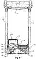
- FIG. 6is a front view of the exercise device shown in FIG. 2 ;
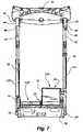
- FIG. 7is a rear view of the exercise device shown in FIG. 2 ;
- FIG. 8is a bottom view of the exercise device shown in FIG. 2 ;
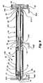
- FIG. 9is a section view taken along line 9 - 9 of FIG. 5 ;
- FIG. 10is a partial cut away isometric view of the exercise device shown in FIG. 2 , the view illustrating the rocker arm orientated in a position corresponding with the left treadle in about the lowest position and the right treadle in about the highest position;
- FIG. 11is a partial cut away isometric view of the exercise device shown in FIG. 2 , the view illustrating the rocker arm orientated in a position corresponding with the left treadle in a position higher than in FIG. 10 and the right treadle in a position lower than in FIG. 10 ;
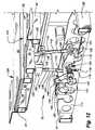
- FIG. 12is a partial cut away isometric view of the exercise device shown in FIG. 2 , the view illustrating the rocker arm orientated in a position corresponding with the left treadle about parallel with the right treadle;
- FIG. 13is a partial cut away isometric view of the exercise device shown in FIG. 2 , the view illustrating the rocker arm orientated in a position corresponding with the left treadle in a position higher than in FIG. 12 and the right treadle in a position lower than in FIG. 12 ;
- FIG. 14is a partial cut away isometric view of the exercise device shown in FIG. 2 , the view illustrating the rocker arm orientated in a position corresponding with the left treadle in a position higher than in FIG. 13 and the right treadle in a position lower than in FIG. 13 ;
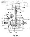
- FIG. 15is a left side view of one embodiment of a rocker arm type interconnection structure, in accordance with aspects of the present invention.
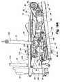
- FIG. 16Ais an isometric view of the exercise device shown in FIG. 2 , the exercise device with the left treadle in about the lowest position and the right treadle in about the highest position;
- FIG. 16Bis a left side view of the exercise device in the orientation shown in FIG. 16A and with a representative user;
- FIG. 17Ais an isometric view of the exercise device shown in FIG. 2 , the exercise device with the left treadle higher than shown in FIG. 16A , and the right treadle lower than shown in FIG. 16A ;
- FIG. 17Bis a left side view of the exercise device in the orientation shown in FIG. 17A and with a representative user;
- FIG. 18Ais an isometric view of the exercise device shown in FIG. 2 , the exercise device with the left and right treadle about parallel and collectively at about a 10% grade;
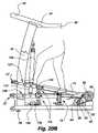
- FIG. 18Bis a left side view of the exercise device in the orientation shown in FIG. 18A and with a representative user;
- FIG. 19Ais an isometric view of the exercise device shown in FIG. 2 , the exercise device with the left treadle higher than shown in FIG. 18A , and the right treadle lower than as shown in FIG. 18A ;
- FIG. 19Bis a left side view of the exercise device in the orientation shown in FIG. 19A and with a representative user;
- FIG. 20Ais an isometric view of the exercise device shown in FIG. 2 , the exercise device with the left treadle in about its highest position and the right treadle in about its lowest position;
- FIG. 20Bis a left side view of the exercise device in the orientation shown in FIG. 20A and with a representative user;
- FIG. 21is an isometric view of an alternative exercise device employing a single rear roller supported in virtual pivot arrangement
- FIG. 22is an isometric view of the single rear roller supported in virtual pivot arrangement
- FIG. 23is an isometric view of the single rear roller supported in virtual pivot arrangement, with belts removed to show additional features
- FIG. 24is a side view of a first embodiment of an exercise device employing an upper body exercise assembly
- FIG. 25is a side view of a second embodiment of an exercise device employing an upper body exercise assembly
- FIG. 26is a side view of a third embodiment of an exercise device employing an upper body exercise assembly
- FIG. 27is a side view of a fourth embodiment of an exercise device employing an upper body exercise assembly
- FIG. 28is a side view of a fifth embodiment of an exercise device employing an upper body exercise assembly
- FIG. 29is a side view of a sixth embodiment of an exercise device employing an upper body exercise assembly
- FIG. 30is a side view of a seventh embodiment of an exercise device employing an upper body exercise assembly
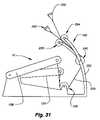
- FIG. 31is a side view of a eighth embodiment of an exercise device employing an upper body exercise assembly
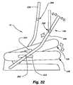
- FIG. 32is a side view of a ninth embodiment of an exercise device employing an upper body exercise assembly
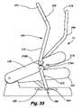
- FIG. 33is a side view of a tenth embodiment of an exercise device employing an upper body exercise assembly
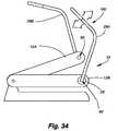
- FIG. 34is a side view of an eleventh embodiment of an exercise device employing an upper body exercise assembly
- FIG. 35is a side view of a twelfth embodiment of an exercise device employing an upper body exercise assembly
- FIG. 36is a side view of a thirteenth embodiment of an exercise device employing an upper body exercise assembly
- FIG. 37is a side view of a fourteenth embodiment of an exercise device employing an upper body exercise assembly
- FIG. 38is a side view of a first embodiment of an exercise device employing a flywheel operably coupled with tread belts supported on each treadle assembly;
- FIG. 39is a side view of a second embodiment of an exercise device employing a flywheel operably coupled with tread belts supported on each treadle assembly;
- FIG. 40is a side view of a third embodiment of an exercise device employing a flywheel operably coupled with tread belts supported on each treadle assembly;
- FIG. 41is a side view of a fourth embodiment of an exercise device employing a flywheel operably coupled with tread belts supported on each treadle assembly;
- FIGS. 41A , 41 B, and 41 Care a top view, right side view, and left side view, respectively, of a pulley arrangement for coupling the flywheel of FIG. 41 with the tread belts;
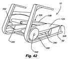
- FIG. 42is a side view of a fifth embodiment of an exercise device employing one or more flywheels operably coupled with tread belts supported on each treadle assembly;
- FIG. 43is a side view of a sixth embodiment of an exercise device employing one or more flywheels operably coupled with tread belts supported on each treadle assembly;
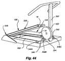
- FIG. 44is a side view of a seventh embodiment of an exercise device employing a flywheel operably coupled with tread belts supported on each treadle assembly;
- FIG. 45is a side view of an eighth embodiment of an exercise device employing a flywheel operably coupled with tread belts supported on each treadle assembly;
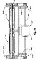
- FIG. 46is a section view of a motor assembly coupled with rear rollers.
- An exercise device 10 conforming to the present inventionmay be configured to provide a user with a walking-type exercise, a stepping-type exercise or a climbing-like exercise that is a combination of both walking and stepping.
- the exercise devicegenerally includes two treadmill-like assemblies 12 (referred to herein as a “treadle” or a “treadle assembly”) pivotally connected with a frame 14 so that the treadles may pivot up and down about an axis 16 .
- the axismay be a physical axis (axle) or may be a virtual axis defined by assemblies of components that pivotally support each treadle.
- each treadleincludes a tread belt 18 that provides a moving surface like a treadmill.
- the tread beltis supported, in one example, by a front roller and a rear roller.
- the rear rollermay be common to both treadles or each treadle may include a distinct rear roller.
- the rear roller(s)may be supported on the frame or treadle, and may share an axis of rotation with the treadles or may have a unique axis of rotation forward, rearward, above an/or below the pivot axis of the treadles.
- a userwill walk, jog, or run on the treadles and the treadles will reciprocate about the treadle pivot axis.
- the treadlesare interconnected so that upward movement of one treadle is accompanied by downward movement of the other treadle.
- the combination of the moving surface of the tread belts and the coordinated and interconnected reciprocation of the treadlesprovides an exercise that is similar to climbing on a loose surface, such as walking, jogging, or running up a sand dune where each upward and forward foot movement is accompanied by the foot slipping backward and downward.
- Extraordinary cardiovascular and other health benefitsare achieved by such a climbing-like exercise.
- the extraordinary health benefitsare achieved in a low impact manner.
- FIGS. 1-23provides a general structural framework for various other embodiments discussed with reference to FIGS. 24-47 . Further detail concerning other structural frameworks for the various embodiments discussed herein are provided in the various related applications incorporated by reference herein. Aspects of the present invention involve various structures that may be employed to provide an upper body exercise component to the embodiments discussed with reference to FIGS. 1-23 as well as the various embodiments incorporated by reference herein. Aspects of the present invention also involve various structures that may be employed to replace or accompany the motor or motors used to drive the tread belts. Finally, aspects of the present invention involve various combinations of the upper body exercise structures, non-motorized structures, and resistance structures, as well as the numerous combinations of possible embodiments described in the related applications incorporated by reference herein.
- FIG. 1is an isometric view of one example of an exercise device conforming to aspects of the present invention.
- the embodiment of the exercise device illustrated in FIG. 1includes protective and decorative panels 20 , which in some instances obscure the view of some components of the exercise device.
- FIG. 2is an isometric view the exercise device illustrated in FIG. 1 with the protective and decorative panels removed to better illustrate all of the components of the device. Views of the exercise device shown in FIGS. 3-8 , and others, in most instances, do not include the protective and decorative panels.
- the exercise deviceincludes a first treadle assembly 12 A and a second treadle assembly 12 B, each having a front portion 22 and a rear portion 24 .
- the rear portions of the treadle assemblies 12are pivotally supported at the rear of the exercise device 10 .
- the front portions 22 of the treadle assembliesare supported above the frame 14 , and are configured to reciprocate in a generally up and down manner during use. It is also possible to pivotally support the treadles at the front of the exercise device, and support the rear of the treadle assemblies above the frame.
- the treadle assembliesalso each support an endless belt or “tread belt” that rotates over a deck 26 and about front 28 and rear 30 rollers to provide either a forward or rearward moving surface.
- a usermay perform exercise on the device facing toward the front of the treadle assemblies (referred to herein as “forward facing use”) or may perform exercise on the device facing toward the rear of the treadle assemblies (referred to herein as “rearward facing use”).
- forward facing usethe user may walk, jog, run, and/or step on the exercise device in a manner where each of the user's feet contact one of the treadle assemblies.
- forward facing usethe user's left foot will typically only contact the left treadle assembly 12 A and the user's right foot will typically only contact the right treadle assembly 12 B.
- rearward facing usethe user's left foot will typically only contact the right treadle assembly 12 B and the user's right foot will typically only contact the left treadle assembly 12 A.
- An exercise device conforming to aspects of the inventionmay be configured to only provide a striding motion or to only provide a stepping motion.
- the treadle assembliesare configured to not reciprocate and the endless belts 18 configured to rotate.
- the term “striding motion”is meant to refer to any typical human striding motion such as walking, jogging and running.
- the treadle assembliesare configured to reciprocate and the endless belts are configured to not rotate about the rollers.
- stepping motionis meant to refer to any typical stepping motion, such as when a human walks up stairs, uses a conventional stepper exercise device, walks up a hill, etc.
- each treadle assemblyis pivotally supported at the rear of the exercise device.
- the front of each treadle assemblyis supported above the front portion of the exercise device so that the treadle assemblies may pivot upward and downward.
- the associated treadle assembly 12 A, 12 B(including the belts) will pivot downwardly.
- the treadle assemblies 12are interconnected such that downward or upward movement of one treadle assembly will cause a respective upward or downward movement of the other treadle assembly.
- the associated treadle assemblywill pivot downwardly while the other treadle assembly will pivot upwardly.
- FIG. 2is a partial cutaway isometric view of the embodiment of the exercise device 10 shown in FIG. 1 .
- the tread beltis removed to show the underlying belt platform or “deck” 26 and the front roller 28 and the rear roller 30 .
- the belt platform of the left treadleis partially cut away to show the underlying treadle frame components.
- the exercise deviceincludes the underlying main frame 14 .
- the frameprovides the general structural support for the moving components and other components of the exercise device.
- the frameincludes a left side member 32 , a right side member 34 and a plurality of cross members 36 interconnecting the left side and right side members to provide a unitary base structure.
- the framemay be set directly on the floor or a may be supported on adjustable legs, cushions, bumpers, or combinations thereof.
- adjustable legs 38are provided at the bottom front left and front right corners of the frame.
- a left upright 40is connected with the forward end region of the left side member 32 .
- a right upright 42is connected with the forward end region of the right side member 34 .
- the uprightsextend generally upwardly from the frame, with a slight rearward sweep.
- Handles 44extend transversely to the top of each upright in a generally T-shaped orientation with the upright.
- the top of the Tis the handle and the downwardly extending portion of the T is the upright.
- the handlesare arranged generally in the same plane as the respective underlying side members 32 , 34 .
- the handlesdefine a first section 46 connected with the uprights, and a second rearwardly section 48 extending angularly oriented with respect to the first section.
- the handleis adapted for the user to grasp during use of the exercise device.
- a console 50is supported between the first sections of the handles.
- the consoleincludes one or more cup holders, an exercise display, and one or more depressions adapted to hold keys, a cell phone, or other personal items.
- the consoleis best
- each treadle assemblyincludes a treadle frame 52 having a left member 54 , a right member 56 , and a plurality of treadle cross members 58 extending between the left and right members.
- the outside longitudinal members 54 , 56 of each treadleare pivotally coupled to the rear axis (axle) 16 by radial ball bearings 59 .
- each front roller 28is adjustably connected with the front of each treadle frame.
- the front rollerincludes an axle 60 extending outwardly from both ends of the roller.
- the outwardly extending ends of the axleeach define a threaded aperture, 62 and are supported in a channel 64 defined in the forward end of the left 54 and right 56 treadle frame side members.
- the channeldefines a forwardly opening end 66 .
- a plate 68 defining a threaded apertureis secured to the front end of the left and right members so that the centerline of the aperture 70 is in alignment with the forward opening end 66 of the channel 64 .
- a boltis threaded into the threaded aperture and in engagement with the corresponding threaded aperture in the end of the roller axle 60 supported in the channel.
- a springis located between the closed rear portion of the channel and the pivot axle to bias the pivot axle forwardly.
- the belt decks 26are located on the top of each treadle frame 52 .
- the deckmay be bolted to the treadle frame, may be secured to the frame in combination with a deck cushioning or deck suspension system, or may be loosely mounted on the treadle frame.
- Each belt deckis located between the respective front 28 and rear 30 rollers of each treadle assembly 12 A, 12 B.
- the belt decksare dimensioned to provide a landing platform for most or all of the upper run of the tread belts 18 .
- each treadle assemblyis pivotally supported at the rear of the frame, and the front of each treadle assembly is supported above the frame by one or more dampening elements 76 , an interconnection member 78 , or a combination thereof, so that each treadle assembly 12 may pivot up and down with respect to the lower frame.
- FIG. 7is a rear view of the embodiment of the exercise device shown in FIG. 2 .
- FIG. 9is a section view of the rear roller assembly taken along line 9 - 9 of FIG. 5 . Referring to FIGS. 5 , 7 , 9 and others, each treadle assembly is pivotally supported above a rear cross member 80 of the main frame 14 .
- a drive shaft 82is rotatably supported above the rear cross member by a left 84 A, middle 84 B, and right 84 C drive bracket.
- Corresponding radial bearings 81 A, 81 B and 81 Crotatably support the axle in the brackets.
- the drive shaftrotatably supports each rear roller.
- the left and right rear rollersare rotatably supported about a common drive axis 82 , which is also the common rear pivot axis 16 of the treadles 12 , in one example.
- Each roller 30is supported on the axle 82 by a pair of collars 83 .
- the collarsare secured to the axle by a key 85 that fits in a channel 87 , 89 in the collar and in the axle.
- the collaris further secured to the axle by a set screw 91 supported in the collar. The set screw is tightened against the key.
- a pulley 86is secured to a portion of the drive shaft 82 . As shown in FIGS. 2 , 3 , 9 and others, in one particular implementation, the drive pulley 86 is secured to the left end region of the drive shaft. However, the drive pulley may be secured to the right end region, or somewhere along the length of the drive shaft between the left and right end regions.
- a motor 88is secured to a bottom plate 90 (best shown in the bottom view of FIG. 8 ) that extends between the right 56 and left 54 side members.
- a motor shaft 92extends outwardly from the left side of the motor. The motor is mounted so that the motor shaft is generally parallel to the drive shaft 82 .
- a flywheel 94is secured to the outwardly extending end region of the motor shaft.
- a drive belt 96is connected between the drive shaft pulley and a motor pulley 98 connected with the motor shaft. Accordingly, the motor is arranged to cause rotation of the drive shaft and both rear rollers 30 .
- a belt speed sensor 100is operably associated with the tread belt 18 to monitor the speed of the tread belt.
- the belt speed sensoris implemented with a reed switch 102 including a magnet 104 and a pick-up 106 .
- the reed switchis operably associated with the drive pulley to produce a belt speed signal.
- the magnetis imbedded in or connected with the drive pulley 86
- the pick-upis connected with the main frame 14 in an orientation to produce an output pulse each time the magnet rotates past the pick-up.
- Both the left and right rear rollers 30are secured to the drive shaft 82 .
- rotation of the drive shaftcauses the left and right rear rollers and also the associated endless belts 18 to rotate at, or nearly at, the same pace.
- independent drive shafts for each rollerthat would be powered by separate motors, with a common motor control. In such an instance, motor speed would be coordinated by the controller to cause the tread belts to rotate at or nearly at the same pace.
- the motor or motorsmay be configured or commanded through user control to drive the endless belts in a forward direction (i.e., from the left side perspective, counterclockwise about the front and rear rollers) or configured to drive the endless belts in a rearward direction (i.e., from the left side perspective, clockwise about the front and rear rollers).
- the tread belt 18slides over the deck 26 with a particular kinetic friction dependant on various factors including the material of the belt and deck and the downward force on the belt.
- the beltmay slightly bind on the deck when the user steps on the belt and increases the kinetic friction between the belt and deck.
- the flywheel 94 secured to the motor shafthas an angular momentum force component that helps to overcome the increased kinetic friction and help provide uniform tread belt movement.
- the deckis a 3 ⁇ 8′′ thick medium density fiber based (or “MDF”) with an electron beam low friction cured paint coating.
- the beltis a polyester weave base with a PVC top.
- the beltmay further incorporate a low friction material, such as low friction silicone.
- Resistance elementoperably connected with the treadles.
- resistance elementis meant to include any type of device, structure, member, assembly, and configuration that resists the vertical movement, such as the pivotal movement of the treadles.
- the resistance provided by the resistance elementmay be constant, variable, and/or adjustable.
- the resistancemay be a function of load, of time, of heat, or of other factors.
- Such a resistance elementmay provide other functions, such as dampening the downward, upward, or both movement of the treadles.
- the resistance elementmay also impart a return force on the treadles such that if the treadle is in a lower position, the resistance element will impart a return force to move the treadle upward, or if the treadle is in an upper position, the resistance element will impart a return force to move the treadle downward.
- shockor “dampening element” is sometimes used herein to refer to a resistance element, or to a spring (return force) element, or a dampening element that may or may not include a spring (return) force.
- a resistance element 76extends between each treadle assembly 12 and the frame 14 to support the front of the treadle assemblies and to resist the downward movement of each treadle.
- the resistance element or elementsmay be arranged at various locations between treadle frame and the main frame.
- the resistance elementsinclude a first 108 and a second 110 shock.
- the shockboth resists and dampens the movement of the treadles. More particularly, the first or left shock 108 extends between the left or outer frame member 54 of the left treadle assembly and the left upright frame member 40 .
- the second shock 110extends between the right or outer frame member 56 of the right treadle assembly and the right upright frame member 42 .
- the shocksextend between the outer frame members of each treadle assembly and a portion of the frame below the treadle assembly. In another alternative, the shocks may be connected to the front of the treadles between the inner and outer treadle frame members.
- the shock( 108 , 110 ) is a fluid-type or air-type dampening device and is not combined internally or externally with a return spring.
- the shockdampens and resists the downward force of the footfall to provide cushioning for the user's foot, leg and various leg joints such as the ankle and knee.
- the resistance devicemay also be adjusted to decrease or increase the downward stroke length of a treadle.
- the shockmay be provided with a user adjustable dampening collar, which when rotated causes the dampening force of the shock to either increase or decrease to fit any particular user's needs.
- the shockincludes a cylinder filled with hydraulic fluid.
- a piston rodextends outwardly from the cylinder.
- a pistonis connected with the piston rod.
- the pistondefines at least one orifice through which hydraulic fluid may flow, and also includes a check valve.
- the pistonsubdivides the cylinder into two fluid filled chambers.
- the pistoneither moves up or down in the cylinder.
- the fluidflows through the orifice at a rate governed partially by the number of orifices and the size of the orifices.
- the fluidflows through the check valve.
- the collaris operably connected with a plate associated with the orifice or orifices.
- the dampening resistance collaris connected with a tapered plunger directed into an orifice between the hydraulic chambers of the shock.
- the depth of the plungerwill govern, in part, the resistance of the shock.
- the return spring shown in FIG. 4 of the '587 patentis removed.
- shockmay be used in an exercise device conforming to the present invention.
- the shockmay be used with the spring 252 shown in FIG. 10 of the '527 patent.
- the springprovides a return force that moves or returns the treadles upward after they are pressed downward.
- the spring 252is removed.
- the shockonly provides a resistance and does not provide a return force.
- the shockmay be arranged to provide a resistance in the range of 47 KgF to 103 KgF. Alternative resistance elements are discussed in more detail below.
- FIGS. 10-14are partial isometric views of the exercise device particularly illustrating the treadle interconnection structure 78 .
- Each of FIGS. 10-14show the interconnection structure in a different position.
- FIG. 15is a side view of the treadle interconnection structure in the same position as is shown in FIG. 12 .
- FIGS. 16 (A,B)- 20 (A,B)are isometric views of the exercise device corresponding with the views shown in FIGS. 10-14 .
- the interconnection structureincludes a rocker or “teeter” arm assembly 112 pivotally supported on a rocker cross member 114 extending between the left 32 and right 34 side members of the frame.
- the rocker arm assemblyis operably connected with each treadle assembly 12 .
- the rocker cross memberdefines a U-shaped cross section.
- Each upstanding portion of the Udefines a key way 116 .
- the top of the key waydefines a pivot aperture 118 .
- the rocker armincludes a rocker or interconnect pivot axle 120 that is supported in and extends between each pivot aperture to pivotally support the rocker arm.
- the key wayprovides a way for the interconnect structure to be moved between a “shipping” position and a “use” position.
- the left and right outer portions of the rocker arminclude a first or left lower pivot pin 122 and a second or right lower pivot pin 124 , respectively.
- a generally L-shaped bracket 126 supporting a first upper pivot pin 128extends downwardly from the inner or right side member 56 of the left treadle 12 A so that the upper pivot pin is supported generally parallel, below, and outwardly of the inner side member.
- a second generally L-shaped bracket 132 supporting a second upper pivot pin 130extends downwardly from the inner or left side tube 54 of the right treadle assembly 12 B so that the upper pivot pin is supported generally parallel, below, and outwardly of the inner side member.
- a first rod 134is connected between the left upper 128 and lower 122 pivot pins.
- a second rod 136is connected between the right upper 130 and lower 124 pivot pins.
- the rodscouple the treadles to the rocker arm.
- each rod ( 134 , 136 )defines a turnbuckle with an adjustable length.
- the tumbucklesare connected in a ball joint 138 configuration with the upper and lower pivot pins.
- a turnbuckledefines an upper and a lower threaded sleeve 140 .
- Each threaded sleevedefines a circular cavity with opposing ends to support a pivot ball.
- the pivot pinsare supported in the pivot balls.
- a roddefines opposing threaded ends 142 , each supported in a corresponding threaded sleeve.
- the treadle assemblies 12may be locked-out so as to not pivot about the rear axis 16 .
- the belts 18 of the treadle assembliescollectively provide an effectively single non-pivoting treadmill-like striding surface.
- the level of the two treadlesmay be precisely aligned so that the two treadles belts, in combination, provide parallel striding surfaces in the lock-out position.
- the interconnection structure 78(e.g., the rocker arm assembly) interconnects the left treadle with the right treadle in such a manner that when one treadle, (e.g., the left treadle) is pivoted about the rear pivot axis 16 downwardly then upwardly, the other treadle (e.g., the right treadle) is pivoted upwardly then downwardly, respectively, about the rear pivot axis in coordination.
- the two treadlesare interconnected in a manner to provide a stepping motion where the downward movement of one treadle is accompanied by the upward movement of the other treadle and vice versa.
- the rocker arm 112pivots or teeters about the rocker axis 120 .
- FIGS. 10-14 and 16 (A,B)- 20 (A,B), the climbing-like exercise provided by the motion of the exercise device 10is described in more detail.
- a representative user(hereinafter the “user”) is shown in forward facing use in FIGS. 16B-20B .
- the useris walking forward and the device is configured for climbing-type use, i.e., so the treadles reciprocate.
- the foot motion shownis representative of only one user.
- the treadles 12may not move between the upper-most and lower-most position, but rather points in between.
- the usermay have a shorter or longer stride than that shown.
- a usermay walk backward, or may face backward, or may face backward and walk backward.
- FIGS. 10 and 16Athe left treadle 12 A is in a lower position and the right treadle 12 B is in an upper position.
- the left side of the rocker arm 112is pivoted downwardly and the right side of the rocker arm is pivoted upwardly.
- FIG. 16Bthe user is shown with his right foot forward and on the front portion of the right tread belt.
- the user's left legwill be extended downwardly and rearwardly with the majority of the user's weight on the left treadle.
- the user's right legwill be bent at the knee and extended forwardly so that the user's right foot is beginning to press down on the right treadle.
- FIGS. 11 , 17 A, and 17 Bshow the orientation of the device 10 and the user in a position after that shown in FIGS. 10 , 16 A, and 16 B.
- the right treadle 12 Bis being pressed downwardly, which, via the rocker interconnection structure 78 , causes the left treadle 12 A to begin to rise.
- the user's right foothas moved rearwardly and downwardly from the position shown in FIG. 16B .
- the user's left foothas moved rearwardly and upwardly from the position shown in FIG. 16B .
- FIGS. 12 , 18 A, and 18 Bshow the right treadle 12 B about midway through its upward stroke, and the left treadle 12 A about midway through its downward stroke.
- the treadle assembliesare nearly at the same level above the frame 14 and the endless belts 18 are also at the same level.
- FIG. 18Bthe user's right foot and leg have moved rearwardly and downwardly from the position shown in FIG. 17B .
- the user's left foothas moved rearwardly and upwardly from the position shown in FIG. 16B .
- the userhas begun to lift the left foot from the left tread belt in taking a forward stride; thus, the left heel is lifted and the user has rolled onto the ball of the left foot.
- more weightwill now be on the right treadle than the left treadle.
- the right treadle 12 Bcontinues it downward movement and the left treadle 12 A continues its upward movement to the orientation of the device as shown in FIGS. 13 , 19 A, and 19 B.
- the left treadleis higher than the right treadle, and the rocker arm 112 is pivoted about the rocker pivot axis 120 such that its right side is lower than its left side.
- the user's right legcontinues to move rearward and downward. The user has lifted the right leg off the left treadle and is moving it forward.
- the userwill step down with his left foot on the front portion of the treadle belt. All of the user's weight is on the right treadle until the user places his left foot on the left treadle. The user continues to provide a downward force on the right treadle forcing the left treadle up.
- FIGS. 14 , 20 A, and 20 Billustrate the right treadle 12 B in about its lowest position, and show the left treadle 12 A in about its highest position.
- the userhas stepped down on the front 22 of the left treadle and has begun pressing downward with the left leg.
- the useris also beginning to lift the right leg.
- the downward force on the left treadlewill be transferred through the interconnection structure 78 to the right treadle to cause the right treadle to begin to rise.
- FIGS. 16 (A,B)- 20 (A,B)represent half a cycle of the reciprocating motion of the treadles, i.e., the movement of the left treadle from a lower position to an upper position and the movement of the right treadle from an upper position to a lower position.
- a complete climbing-type exercise cycleis represented by the movement of one treadle from some position and back to the same position in a manner that includes a full upward stroke of the treadle (from the lower position to the upper position) and a full downward stroke of the treadle (from the upper position to the lower position).
- a step cycle referenced from the lower position of the left treadle(the upper position of the right treadle) will include the movement of the left treadle upward from the lower position to the upper position and then downward back to its lower position.
- a step cycle referenced from the mid-point position of the left treadle(see FIG. 18 ) will include the upward movement of the treadle to the upper position, the downward movement from the upper position, past the mid-point position and to the lower position, and the upward movement back to the mid-point position.
- the order of upward and downward treadle movementsdoes not matter.
- the upward movementmay be followed by the downward movement or the downward movement may be followed by the upward movement.
- the exercise deviceincludes a step sensor 144 , which provides an output pulse corresponding with each downward stroke of each treadle.
- the step sensoris implemented with a second reed switch 146 including a magnet 148 and a pick-up 150 .
- the magnetis connected to the end of a bracket 152 that extends upwardly from the rocker arm 112 .
- the bracketorients the magnet so that it swings back and forth past the pick-up, which is mounted on a bracket 157 connected with the rocker cross member 114 .
- the reed switch 146triggers an output pulse each time the magnet 148 passes the pick-up 150 .
- the reed switchtransmits an output pulse when the right treadle 12 B is moving downward, which corresponds with the magnet passing downwardly past the pick-up, and the reed switch also transmits an output pulse when the left treadle 12 A is moving upward, which corresponds with the movement to the magnet upwardly past the pick-up.
- the output pulsesare used to monitor the oscillation and stroke count of the treadles as they move up and down during use. With additional sensors arranged generally vertically, it is also possible to determine the depth or vertical stroke dimension.
- the output pulsesalone or in combination with the belt speed signal, may be used to provide an exercise frequency display and may be used in various exercise related calculations, such as in determining the user's calorie burn rate.
- each treadleincludes a bottom-out assembly 154 .
- the bottom-out assemblyincludes a generally V-shaped bracket 156 interconnected between the inside and outside members of the treadle frame.
- the vertex region of the V-shaped bracketis oriented downwardly and generally defines a flat mounting surface 158 .
- a block 160is fixed to the lower downwardly facing portion of the mounting surface.
- a bumper 164may be fixed to the cross member 162 to cushion the treadle should it bottom out.
- the blockis fabricated with a hard, non-flexible, plastic.
- the blockmay also be fabricated with a solid or flexible resilient polymer material. In a flexible resilient form, the block will provide some cushioning to enhance the cushioning provided by the bumper, or provide cushions when a bumper is not used, should the block bottom-out on the lock-out cross member during use.
- the exercise device 10may be configured in a “lock-out” position where the treadle assemblies do not pivot upward and downward.
- the treadle assembliesare pivotally fixed so that the tread belts are parallel and at about a 10% grade with respect to the rear of the exercise device.
- the userin a forward facing use, the user may simulate striding uphill, and in a rearward facing use the user may simulate striding downhill.
- FIGS. 21-23illustrate an alternative implementation of an exercise device 10 .
- each treadle12 A, 12 B includes a tread belt 18 that provides a moving surface like a treadmill.
- Each tread beltis supported by a front roller and a rear roller.
- the rear roller 166is common to both treadles.
- the rear rollermay be supported on the frame or treadle, and may share an axis of rotation with the treadles or may have a unique axis of rotation forward, rearward, above an/or below the pivot axis of the treadles.
- opposing end portions of the rear rollerare rotatably supported at the rear end of the frame.
- the outer members 54 , 56 of the left 12 A and right 12 B treadles, respectively,are rotatably supported by the outer end portions of the rear roller.
- inner members 56 , 54 of the left 12 A and right 12 B treadles, respectively,are not coupled with the rear roller, but instead, are coupled with the frame through an inner support structure that defines a virtual pivot 168 .
- the inner support structureincludes brackets 170 , 172 extending rearward from the inner sides 56 , 54 of the treadles, which are movingly coupled with at least one stud connected with the rear end of the frame.
- the inner support structurethus allows each treadle to be positioned more closely to one another along the inner sides than a comparable exercise device having two separate rear rollers.
- the inner support structurealso allows the inner sides of each treadle to move about a central pivot of the rear end of each treadle as if it was supported at the central pivot even though the inner support structure is not located directly at the location of the pivot motion.
- each treadle assembly 12is pivotally supported above a rear support structure 174 of the main frame 14 .
- the rear support structureincludes a rear drive casting 176 supported by a rear frame support 178 .
- drive bracketsextending upward from the rear drive casting rotatably support opposing end portions of the rear roller 166 .
- An inner support structure 168 pivotally supporting the insides of the treadle framesincludes a mounting block 180 extending upwardly from the rear drive casting between opposing end portions thereof. As described in more detail below, the mounting block supports the inside longitudinal members 54 , 56 of the treadle frames 52 .
- axle ends 182 A, 182 B of the rear roller 166are rotatably supported above the rear drive casting 176 by the left drive bracket 84 A and the right drive bracket 84 B.
- Corresponding radial bearings 81 A and 81 Brotatably support the axle ends in the brackets.
- the right and left drive bracketsare bolted to a pair of flanges 184 extending upward from opposing end portions of the rear drive casting.
- the inner support structure 168acts to support the inside longitudinal members 56 , 54 of the treadles 12 A, 12 B, respectively. More particularly, the inner support structure includes inner brackets 170 , 172 extending from the treadle frame members 56 , 54 slidingly coupled with studs 186 A, 186 B extending from opposite sides of the mounting block 180 . Inner brackets connected with the treadle frames are slidingly coupled with the studs on the mounting block and act to support the inside longitudinal members of the treadle frames. The inner brackets include a curved portion extending downwardly and rearwardly from the rear ends of the inside longitudinal members 54 , 56 .
- the curved portions of the inner bracketseach define at least one slot 188 A, 188 B therein which are slidingly supported by the studs 186 A, 186 B extending from the mounting block.
- the studs on the mounting blockglide through the slots and thereby support inside longitudinal member of the treadle frame.
- the interaction of the curved portions of the inner brackets and the studsdefines the virtual pivot having a pivot center in common with the rear pivot axis.
- FIGS. 24-37illustrate various exercise devices including an upper body exercise (arms, chest, back, shoulders, etc.) feature or features, in addition to the lower body exercise provided by the exercise devices shown in FIGS. 1-23 .
- FIGS. 24-37 discussed in detail beloware based upon the exercise devices discussed with reference to FIGS. 1-23 above. Many features of the exercise device, not directly relevant to the upper body features, are not included in the drawings. It should be recognized, however, that any implementation of an exercise device with upper body features would include some arrangement of some, many, or all of the features not shown in FIGS. 24-37 , but shown in FIGS. 1-23 .
- the term “upper body exercise” structure, assembly, or the likeis meant to refer to any assembly of components that a user grasps with his or her hands, or otherwise engages with a portion of his or her upper body, to exercise any portion of his or her upper body, including arm, chest, back, trunk, abdomen, etc.
- the term “resistance member”is meant to refer to any type of resistance member, assembly, resistance element defined herein, or structure that imparts a force that a user acts on or against when actuating or acting on an upper body exercise structure.
- resistance membersinclude, but are not limited to, the treadles, a resistance element or structure acting directly or indirectly on the treadles, shocks, flexible resilient members, such as Power Rod technology, weight stack assemblies, SpiralFlex type packs or an assembly thereof, flexible and resilient cabling, and the like.
- FIG. 24depicts a first embodiment of a dual-deck exercise device 10 employing an upper body exercise structure 190 .
- handlebars 192are affixed to each treadle ( 12 A, 12 B) by first and second uprights ( 194 , 196 ).
- the uprightsmay be of varying lengths and configurations. Further, one, three, or more uprights may be used to secure each handlebar to respective treadles.
- the uprightsare coupled with the left treadle frame member 54 (left treadle) and the right treadle frame member 56 (right treadle).
- the handlebaris slightly curved.
- the handlebarmay be any shape.
- the uprights ( 40 , 42 ) and the handlebars 44 and console 50 of FIGS. 1-20are not present.
- the consolein one example, is located atop a pillar extending upwardly from the front region of the frame and forward the treadles, such as shown in FIG. 25 .
- the joinder between uprights and treadleis fixed, rather than pivotal.
- the left treadle 12 Ais an upper pivotal orientation
- the right treadle 12 Bis in a lower pivotal orientation.
- Each handlebaroscillates with the pivotal motion of the associated treadle.
- the handle 192is also pivoted upwardly.
- the handle 192By grasping the handle 192 and pressing down to push the treadle down or pulling up to pull the treadle up, the user may achieve upper body exercise to accompany lower body and cardiovascular benefits.
- the useris acting against one or all of the forces from the treadle interconnection, treadle movement, treadle resistance structure, etc.
- FIG. 25depicts a second embodiment of a dual-deck exercise device 10 employing an upper body exercise structure 190 .
- the embodiment of FIG. 25is similar in function to the embodiment of FIG. 24 .
- handles 192extends upwardly and forwardly from the outside rear of each treadle.
- Each handlemay include one or more uprights 194 attaching the handle to the treadle at a second point.
- the exercise device of FIG. 25includes an upright or pillar 198 extending upward from the front of the frame. The pillar supports the console 20 .
- FIG. 26depicts a third embodiment of a dual-deck exercise device 10 employing an upper body exercise structure 190 .
- uprights( 202 , 204 ) extend upwardly adjacent the rear outside of each treadle.
- a cross member 206extends between the top of each upright.
- a handle 208is pivotally coupled with the front region of the cross member. The handle extends forwardly from the cross member generally above and parallel with the outside edge of the associated treadle. As such, during use, the handles are generally positioned to either side of the user.
- the handlebars 208are hingedly attached to the treadles ( 12 A, 12 B) by a variety of hinge joints and fixed-length members 210 .
- the upward pivotal movement of a treadleis associated with a downward pivoting of the associated handle.
- the downward movement of a treadleis associated with the upward pivoting of the associated handle.
- a user presses downward on the handleit acts to pull upward, via the linkage assemblies 210 , on the associated treadle.
- a user pulls upward on a handleit acts to push downward, via the linkage assemblies, on the associated treadle.
- Each hinge assembly 210includes a first member 212 coupled with the outside member ( 56 , 54 ) of each treadle assembly.
- the first memberextends upward and generally perpendicular the treadle assembly.
- a second member 214is pivotally coupled with the first member.
- the second memberextends generally rearward the first member.
- a third member 216is pivotally coupled with the second member, distal the pivotal connection with the first member.
- the third memberis also pivotally coupled with the handle 208 .
- the handleincludes a downwardly extending section 218 below the handle's pivotal connection with the cross member 206 .
- the third memberis pivotally coupled with the downwardly extending section.
- the membersextend or contract around the hinge joints as a treadle raises and/or a handlebar lowers in order to maintain the operative connection between the two elements. Further, the members and hinge joints may be configured to permit the handlebar to move either towards or away from the treadle as the treadle moves upwardly or downwardly.
- Downward force on the handle 208acts to rotate the downwardly extending section 218 rearward.
- the rearward movement of the downward section of the handlepushes both the third 216 and second 214 members rearwardly, which imparts an upward and rearward force on the first members 212 .
- the forces on the first members 212act to impart an upward force on the respective treadle.
- the upward or downward forces on the treadleacts to impart a downward or upward force, respectively, on the handles.
- FIG. 27depicts a fourth embodiment of a dual-deck exercise device 10 employing an upper body exercise structure 190 .
- the upper body exercise structureincludes a cable 220 coupled with a flexible resilient resistance member 222 or members. Pulling on the cable causes the resistance member to bend.
- a flexible resilient memberthat may be employed is the Bowflex Power Rod®.
- Resistance members, such as a Power Rod®are similar to the resistance rods disclosed in U.S. Pat. No. 4,620,704, titled “Universal Exercising Machine,” filed on Apr. 27, 1984, and U.S. Pat. No. 4,725,057, titled “Universal Exercising Machine,” filed on Nov. 3, 1986, both of which are hereby incorporated by reference herein.
- Embodiments conforming to aspects of the inventionmay employ one or more resistance members 222 to either side of the user.
- the resistance membersextend rearwardly from a frame section 224 at the front of the exercise device.
- the rodsare arranged to the outer sides of each treadle, and are generally parallel with the side of the treadle. It is possible to orient the resistance members in other ways, such as vertically or laterally (like wings), etc., in order to provide a different upper body type exercise. For example, in an embodiment with the power rods oriented vertically to the front of the user, such as in FIG. 28 , the user would exercise different muscles than with the power rods located below the user.
- resistance membersare shown to each side of the respective treadles; however, any number of resistance members may be employed.
- the resistance memberscan have varying diameters and lengths.
- a usercan connect a desired number of resistance rods with a hook connected with an end of the cable. Sufficient force applied to the resistance cable (resistance member) will cause the resistance rods connected thereto to bend, which imparts resistance against the cable force. Because the rods are resilient, when the force is lessened or removed from the resistance cable, the connected resistance rods will tend to be biased to return to a substantially straight orientation.
- handle structures 226extend in a generally arcuate configuration between the front of the device and the rear of the device, at each side of the user. Additionally, a bar 228 extends rearward from an area near the upper apex area of the arcs formed by the handles. A pulley 230 is coupled to the handle structure. The pulley may be connected to any stable surface of the exercise device. Additionally, other structures may be added to the exercise device to support the pulley in different orientations, or to support multiple pulleys the cable is routed through the pulley, with one end of the cable including the hook or other fastening means to connect to the underlying resistance members 222 and the other end of the cable including a handle 232 .
- the usergrasps one or both of the handles, and pulls to actuate and bend the resistance member 222 .
- the resistance member 222In use, the user grasps one or both of the handles, and pulls to actuate and bend the resistance member 222 .
- differing amounts of forcewill be required to bend the member or members.
- FIG. 28depicts an embodiment of a dual deck exercise device including an upper body exercise component 190 similar to that shown in FIG. 27 , but with the flexible resilient resistance members 222 located vertically and to the front of the exercise device 10 and with a differently arranged handle structure.
- a cable 220 and pulley arrangement to the outside of each treadleis employed.
- a pulley 230is supported on an upright 234 that extends upwardly from the frame and to the outside of the right treadle 128 .
- the upright pulleymay include a second pulley 236 that captures the cable so that the cable may be pulled in a variety of directions employing an upper body exercise assembly without disengaging from the pulleys.
- a second pulley 238is supported on the frame below and slightly forward of the front of the right treadle.
- a set of resistance members 222in this case a set of resilient flexible members, such as a Power Rod®, extend upward from the frame in front of the treadles.
- the cable 220is routed through the pulleys ( 230 , 238 ), with one end having a hook to connect with one or more resistance members, and the other end having a handle 232 .
- forceis transferred by way of the cable to bend the one or ore resistance members.
- the resistance memberstraightens into its original shape.
- the number of pulleys and the positioning of the pulley(s)may be arranged to provide any number of different upper body exercises.
- the pulley ( 230 , 236 )may be movably connected with the upright 234 or frame to allow for adjustment of the upper body exercise.
- FIG. 29depicts an embodiment of a dual deck exercise device 10 similar to that shown in FIGS. 27 and 28 , but with the flexible resilient resistance structures 222 arranged generally vertically and to the rear of the exercise device.
- PowerRod® technologymay be used for the resistance structures.
- a cable 220is routed around the pulley.
- the cableincludes a hook or other fastening device for attaching to the resistance members.
- the opposite end of the cableincludes a handle 232 . The user grasps the handle pulls to impart a force on the resistance member(s). As such, the user may obtain an upper body exercise.
- FIG. 30depicts another embodiment of a dual-deck device 10 employing an upper body exercise assembly 190 including resistive elements and a pulley system.
- This embodimentcouples the resistive elements 222 (e.g. PowerRod®) to the treadles, rather than handlebars.
- the resistive membermay be characterized as a “resistance element” as that term is defined above.
- the resistance members 222are vertically oriented and coupled with the frame to the front of the treadles.
- a first pulley 240is coupled to the frame slightly forward and below the right set of resistance members.
- a second pulley 242is arranged on a pedestal 244 rearward the resistance members, and forward the right treadle.
- a cable 220is routed from the top of the resistance member(s) through the pulleys and to the front or side of the respective treadle.
- Each treadleis coupled in the same way to same basic arrangement of a pulley, cable, and resistance element configuration. Downward movement or force of the treadles acts to bend the respective resistance members, and as such is resisted.
- the rodsare resilient, when the force is lessened or removed from the resistance cable, the connected resistance rods will tend to be biased to return to a substantially straight orientation. As such, upward movement of the treadles is assisted by the resistance members.
- the resistance membersperform both a treadle pivot resistance function as well as a treadle return function.
- the resistive elementexerts force against a downward treadle motion, forcing the user to work harder to lower the treadle and enhancing a lower-body workout.
- multiple resistive elementsmay be employed.
- handles 246may be pivotally coupled with the resistance members so that the user may pull back on the resistance members 222 or resist the forward pull on the resistance members. In such an embodiment, adequate clearance between the pedestal pulleys and respective resistance members would be required.
- FIG. 31depicts another embodiment of a dual-deck exercise device 10 employing an upper body exercise structure 190 .
- the upper body exercise structureincludes cables 220 routed through pulley arrangements and connected with each treadle. Each cable is fitted with a handle 232 at an end opposite the connection with the treadle. A pulling force on the cable acts to pivot the treadles downwardly. Further, upward pivotal movement of the treadles causes a pulling motion on the cable.
- a first pair of pulleys 248is located below the front of each treadle, with one pulley below the left treadle and one below the right treadle.
- a second pair of pulleys 250each pulley aligned with the respective lower pulleys, are coupled with an upstanding frame member 252 located to the front of the treadles.
- a third set of pulleys 254each pulley being aligned with the lower respective pulleys 254 , is located at the top of the upstanding member.
- the sets of pulleysguide a corresponding set of cables 220 between the bottom or each treadle to a location in front of a user on the device.
- the third set of pulleysmay include a set of cable retaining pulleys 256 (shown in dash) immediately below the upper third pulleys. Arranged in this manner, a cable is coupled with the lower framework of each treadle. The cables are routed through a corresponding set of pulleys. Handles are coupled to ends of the pulleys extending from the third set of pulleys.
- the usermay grasp the handles and pull on the cables, which will impart a downward force on the associated treadles.
- the usermay grasp the handle and resist the pull on the cable caused by the downward movement of the treadles.
- FIG. 32depicts yet another embodiment of a dual-deck exercise device 10 employing an upper body exercise structure 190 .
- the upper body exercise structureincludes a first 258 and second 260 handle pivotally coupled with the frame below the rear of each respective treadle.
- the handlesextend upwardly and forwardly to the outside of the respective treadle.
- Each handlemay be attached to a treadle by a pin 262 extending through the handle and resting in a slot 264 defined in a side member of each treadle.
- the handlesare pivotally supported at one location.
- each handlemoves through an arcuate path with both a vertical and horizontal component. The vertical component acts on the slot or is acted on by the slot.
- the handlesmay include a lock pivot 266 located between the free end of the handle and the pin-and-slot arrangement.
- the lock pivotpermits the upper portion of the handle to occupy a variety of positions.
- the upper portion of the handlemay be pivoted through approximately a ninety degree angle, in one example, with respect to the portion of the handle extending downwardly from the lock pivot.
- the upper handle portionmay be frozen at any angle within this range of motion, although alternate embodiments may only permit the upper handle portion to occupy discrete positions within the range.
- the usergrasps the handle ( 258 , 260 ) and presses or pulls to impart a back-and-forth movement to the handles.
- a forceis exerted between the treadles ( 12 A, 12 B) and the handles.
- the exercise resistance at the handlescan also be a function of the type of resistance element coupled with the treadles.
- Various resistance elements or structures configured to impart a resistance force on the pivotal movement of the treadlesare discussed herein and in the various applications incorporated by reference herein.
- FIG. 33depicts a tenth embodiment of a dual-deck exercise device 10 having an upper body exercise structure 190 .
- the upper body exercise structureincludes handles 268 that the user may grasp and either push or pull for upper body exercise.
- the handlesinclude an upper 270 and lower segment 272 joined by toothed gears 274 .
- the upper segmentis pivotally coupled with the outside frame of each respective treadle.
- the upper end of the upper segmentincludes a gripping region 276 .
- the lower end of the upper segment, below the pivotdefines an arcuate toothed surface 278 (i.e., a gear).
- the lower segment 272may include a pin-and-slot arrangement 280 similar to that described above with respect to FIG. 32 .
- the slot 282is defined in a sidewall of the device frame.
- the lower end of the lower segment of the handleincludes an axle 284 arranged in the slot.
- the lower end of the lower segmentmoves back-and-forth in the slot.
- the upper end of the lower segmentis pivotally coupled with the treadle below the pivot for the upper segment. Further, the upper end of the lower segment, above the pivot, defines an arcuate toothed surface 278 A arranged to engage the corresponding gear of the upper segment.
- the lower segments 272move back-and-forth in the slot 280 .
- the back-and-forth motion of the lower end of the lower segmentis accompanied by a rotational movement of the gear 278 A above the pivot.
- Rotational movement of the lower segment gearimparts a corresponding rotational movement of the upper segment gear 278 B.
- the rotational movement of the lower gearpivots the handles 268 back and forth.
- the usermay perform upper body exercise by grasping the handles and pushing or pulling to resist or impart a force on the treadles.
- FIG. 34depicts another embodiment of a dual-deck exercise device 10 employing an upper body exercise feature 190 .
- the upper body structureincludes handles 286 coupled with the outside front of each treadle ( 12 A, 12 B).
- the handlesmay be fixed or pivotally coupled with the treadles. In a pivotally coupling, the pivotal movement may be restricted to a discrete back-and-forth range.
- the pivotal arrangementmay include a resistance member, such as a torsion spring, a shock pivotally coupled between the handle and frame, etc.
- the handlesmay be coupled with the front rollers 28 by way of a one-way bearing or ratchet-and-pawl assembly. As such, the handles may be employed to power or assist treadle belt motion (or vice versa).
- FIG. 35depicts yet another embodiment of a dual deck exercise device 10 employing an upper body exercise structure 190 .
- a generally L-shaped handle member 288is pivotally coupled to the rear of the exercise device.
- the handleincludes a generally vertically oriented section 290 , which is pivotally coupled with the frame.
- a generally horizontally oriented section 292extends forwardly from the upper end of the vertically oriented section.
- the horizontally oriented sections of each handleare positioned above and to the outside of the respective treadle.
- Springs, shocks, or other resistance type members 294may be attached to the vertical section of each handle.
- the resistance structuresresist pivotal movement, either forward, backward, or both, of the vertical section of the respective handles.
- the userpresses downward or pulls upward on the horizontal section of the handle.
- the upward or downward force on the horizontal sectionstranslate to pivotal movement of the vertical sections 290 , which is resisted by the resistance structures 294 .
- FIG. 36depicts yet another dual-deck exercise device 10 embodiment employing an upper body exercise structure 190 .
- the upper body exercise structureincludes exercise handle structures 296 pivotally coupled with a fixed handle structure 298 to either side of the treadles ( 12 A, 12 B). With respect to the right fixed handle structure, it includes two vertical members 300 coupled with the rear portion of the frame. A generally horizontally beam 302 extends between the vertical members and forwardly therefrom. The beam angles upwardly from the rear, and is positioned above and to the outside of the respective treadle.
- the exercise handle 296is generally L-shaped, and is pivotally coupled with the beam at the intersection of the two lengths of the L. The longer length 304 extends forward form the pivot. The shorter length 306 extends downward from the pivot.
- a shock 308is coupled between the short length and the fixed handle structure. As such, the user performs upper body exercise by pushing downward or pulling upward on the long length of the exercise handle, which is resisted by the shock.
- FIG. 37depicts an alternative dual-deck exercise device 10 providing an upper body exercise 190 , again using handles 310 .
- each handleis generally L-shaped, with an elongate length 312 extending upward from a pivotal connection 314 to the frame.
- the pivotal connection for each handleis forward the front of each respective treadle ( 12 A, 12 B).
- the shorter length 316 of the handleextends rearwardly from the pivotal connection.
- a wheel 318protrudes from the rearwardly extending sections 316 .
- Each wheelis arranged below a respective treadle.
- the wheelis adapted to engage the underside of the treadles, and roll back and forth thereon.
- the bottom of the treadlesmay be fitted with an appropriate plate 320 or channel. Downward movement of the treadle causes the wheel 318 to roll backward, which causes the vertical handle section 312 to move rearwardly. Further, forward force on the handle imparts an upward force on the treadle, by way of the wheel.
- FIGS. 38-45illustrate various embodiments of an exercise device employing one or more flywheels to impart rotational momentum to the tread belts. These embodiments may be used with a motor or without a motor. As such, the flywheel may add or enhance movement of the tread belts.
- FIG. 38is an isometric view of a dual deck exercise device 10 having a flywheel 322 coupled with the rear axle 82 .
- the rear axleextends outwardly from either the left or right roller 30 , and also beyond the respective drive bracket 84 A or 84 C.
- the flywheelis coupled with the outwardly extending section of axle.
- FIGS. 39 and 40illustrate an alternative dual deck exercise device having a flywheel 322 coupled with the rear axle 82 to impart a drive force on the tread belts.
- the FIGS. 39 and 40 embodimentfunctions in the same manner as FIG. 38 .
- the flywheelis covered in a shroud 324 that shields the user from inadvertently contacting the flywheel while it is rotating.
- FIG. 41is an isometric view of a dual deck exercise device 10 having a flywheel 322 rotationally supported on the frame below the treadles. The flywheel is oriented to rotate in a generally horizontal plane.
- FIGS. 41A , 41 B, and 41 Cillustrate one example of a pulley arrangement for coupling the flywheel 322 to the rear axle 82 and thereby imparting angular momentum to the tread belts during use.
- FIG. 41Ais a top view of the pulley arrangement
- FIG. 41Bis a right side view of the right side pulleys
- FIG. 41Cis a left side view of the left side pulleys.
- Axle pulleys( 326 , 328 ) are coupled at the outside end regions of the rear axle.
- the pulleysmay be coupled to the axle in generally same manner as the drive pulley 86 .
- a pair of cable routing pulleys( 330 , 332 ) are located forwardly of each axle pulley. The cable routing pulleys are positioned in a plane perpendicular to the plane of the axle pulleys.
- a pulley 334is also located at the top of the flywheel 322 and is coupled with a flywheel axle 336 .
- the cable (or belt) 338is routed in a serpentine manner around all of the pulleys so that it couples the rotation of the flywheel 322 with rotation of the rear axle 82 , and hence rotation of the treads 18 .
- the cableextends rearwardly from the flywheel pulley 334 to the top right routing pulley 330 A. From the top right routing pulley, the cable extends over and around the right axle pulley 326 . The cable extends from the bottom of the right axle pulley to and around the lower right rotating pulley 330 B. From the lower right routing pulley the cable extends to the bottom left routing pulley 332 B.
- the cableis routed under the left axle pulley 328 , around and to the top left routing pulley 332 A. From the top left routing pulley the cable extends back to the flywheel axle pulley 334 . With this routing, when a user begins to walk forward on the tread belts, force is imparted to the rear rollers and rear drive axle 82 . Through the cable and pulley arrangement, the flywheel 322 begins to rotate in a clockwise direction. Once sufficient angular momentum is established, tread belt rotation will be driven to some extent by the flywheel, subject to user input, and whether or not a motor is also coupled with the axle.
- FIGS. 42 and 43depict further embodiments of a dual deck exercise device employing a flywheel 332 to assist in tread rotation.
- flywheelsare rotationally supported at the front of the exercise device to either side of the treadles.
- Each flywheelrotates in a vertical plane.
- Axle pulleys( 326 , 328 ), like those shown in FIG. 42A , are coupled with both outer ends of the drive axle 82 .
- a belt 340is secured between the left axle pulley 328 and a left flywheel pulley 342 .
- the beltmay be directly coupled, or may be routed under a third pulley (not shown) rearward of the flywheel 332 .
- the third pulleyis arranged to drop the belt into a lower profile orientation.
- the right side cableis routed in the same manner as the left.
- the flywheels of FIG. 43have smaller diameter than the flywheels of FIG. 42 , but have a greater thickness than the flywheel of FIG. 42 . Further, the flywheels of FIG. 43 are supported on a common axle 344 ; thus, it would be possible to rotate both flywheels with only one axle pulley 328 and a cable 340 connecting the axle pulley to one of the flywheel pulleys 342 .
- the flywheels of FIG. 42 and 43are operably coupled with the tread belts of each treadle.
- the rear roller or rollersbegin to rotate, which causes the flywheels 322 to begin rotating by way of the cable/pulley arrangement coupling the rear axle 82 to the flywheels.
- the angular momentum generated by the rotating flywheels 372is coupled back to the treads in the same way, to cause the treads to rotate.
- FIG. 44illustrates another alternative arrangement for coupling a flywheel 332 to the treads 18 .
- axle pulleys326 , 328
- An intermediate axle 346is arranged at the front of the frame, below the treads ( 12 A, 12 B).
- Flywheel pulleys( 348 A, B, C) are coupled to each end of the intermediate axle 346 , and at a mid region of the intermediate axle.
- Belts 350are secured between each axle pulley and the respective flywheel pulley.
- the flywheel 322is rotationally supported in a vertical orientation at a front post 352 .
- the flywheel pulley 348 B at the mid region of the intermediate axleis coupled with the flywheel by way of a third belt 354 .
- FIG. 45illustrates another alternative arrangement for coupling a flywheel 322 to the treads 18 .
- the flywheelis rotationally supported in horizontal plane below the treadles.
- axle pulleys( 326 , 328 ) are coupled at each end of the rear axle 82 .
- an intermediate axle 346is provided between the outer frame members, just forward the rear axle.
- Flywheel pulleys( 348 A, B, C) are provided at either end of the intermediate axle, and at a mid region of the axle.
- the outer flywheel pulleysmay be either inside or outside the frame member to align with the axle pulleys.
- Belts 350couple the axle pulleys with the flywheel pulleys.
- a belt 354which may be partially twisted, couples the middle flywheel pulley 348 B with the flywheel 322 .
- rearward belt movementwhich accompanies forward striding, causes the flywheel to rotate clockwise. If the belt between the middle pulley and the flywheel pulley is twisted in the opposite manner, then the flywheel will rotate counter-clockwise.
- the angular momentum from the flywheelcan impart driving force to the tread belts.
- FIG. 46is a schematic of a roller drive system 356 for use on a dual-treadle exercise device using a single motor 358 to turn the rear rollers.
- the use of a single motor to turn two rear rollerseliminates the need to synchronize two motors and lowers the associated manufacturing costs and complexity.
- each treadle assembly ( 12 A, 12 B)includes a separate rear roller rotatably supported on the frame.
- a motor shaft 360runs through the motor and has a drive pulley ( 362 A, 362 B) connected with opposing end portions.
- Each drive pulley ( 362 A, 362 B)is coupled to a respective slave pulley ( 364 A, 364 B) through belts ( 366 A, 366 B).
- Each slave pulleyis connected with or operably associated with a rear roller on each treadle.
- the slave pulleycan be connected directly with the rear roller inside the frame structure, or to the axle 82 end extending outside the frame structure, or in some other manner.
- the drive pulleysactuate the belt, which in turn rotates the slave pulleys to rotate the two separate rear rollers.
- the rear rollersin turn then drive the continuous belt on each treadle.
Landscapes
- Health & Medical Sciences (AREA)
- General Health & Medical Sciences (AREA)
- Physical Education & Sports Medicine (AREA)
- Cardiology (AREA)
- Vascular Medicine (AREA)
- Orthopedic Medicine & Surgery (AREA)
- Life Sciences & Earth Sciences (AREA)
- Biophysics (AREA)
- Rehabilitation Tools (AREA)
Abstract
Description
Claims (5)
Priority Applications (10)
| Application Number | Priority Date | Filing Date | Title |
|---|---|---|---|
| US11/065,746US7517303B2 (en) | 2003-02-28 | 2005-02-25 | Upper body exercise and flywheel enhanced dual deck treadmills |
| CN2005800133002ACN1953787B (en) | 2004-02-26 | 2005-02-28 | Workout Upper Body & Flywheel Enhanced Bikes |
| EP05724323AEP1722869A4 (en) | 2004-02-26 | 2005-02-28 | DOUBLE EXERCISE MACHINE IMPROVED PLATFORM WITH FLYWHEEL AND BODY EXERCISE |
| TW101135263ATW201309363A (en) | 2004-02-26 | 2005-03-01 | Upper body exercise and flywheel enhanced dual deck treadmills |
| TW094106056ATW200536580A (en) | 2004-02-26 | 2005-03-01 | Upper body exercise and flywheel enhanced dual deck treadmills |
| TW100132986ATWI367119B (en) | 2004-02-26 | 2005-03-01 | Upper body exercise and flywheel enhanced dual deck treadmills |
| US12/404,534US7811209B2 (en) | 2003-02-28 | 2009-03-16 | Upper body exchange and flywheel enhanced dual deck treadmills |
| US12/902,884US8147385B2 (en) | 2003-02-28 | 2010-10-12 | Upper body exercise and flywheel enhanced dual deck treadmills |
| US13/438,618US8734299B2 (en) | 2003-02-28 | 2012-04-03 | Upper body exercise and flywheel enhanced dual deck treadmills |
| US14/282,492US9308415B2 (en) | 2003-02-28 | 2014-05-20 | Upper body exercise and flywheel enhanced dual deck treadmills |
Applications Claiming Priority (11)
| Application Number | Priority Date | Filing Date | Title |
|---|---|---|---|
| US45078903P | 2003-02-28 | 2003-02-28 | |
| US45110403P | 2003-02-28 | 2003-02-28 | |
| US45089003P | 2003-02-28 | 2003-02-28 | |
| US54826504P | 2004-02-26 | 2004-02-26 | |
| US54878704P | 2004-02-26 | 2004-02-26 | |
| US54881104P | 2004-02-26 | 2004-02-26 | |
| US54878604P | 2004-02-26 | 2004-02-26 | |
| US10/789,294US7553260B2 (en) | 2003-02-28 | 2004-02-26 | Exercise device with treadles |
| US10/789,182US7621850B2 (en) | 2003-02-28 | 2004-02-26 | Dual deck exercise device |
| US10/789,579US7618346B2 (en) | 2003-02-28 | 2004-02-26 | System and method for controlling an exercise apparatus |
| US11/065,746US7517303B2 (en) | 2003-02-28 | 2005-02-25 | Upper body exercise and flywheel enhanced dual deck treadmills |
Related Parent Applications (3)
| Application Number | Title | Priority Date | Filing Date |
|---|---|---|---|
| US10/789,579Continuation-In-PartUS7618346B2 (en) | 2003-02-28 | 2004-02-26 | System and method for controlling an exercise apparatus |
| US10/789,182Continuation-In-PartUS7621850B2 (en) | 2003-02-28 | 2004-02-26 | Dual deck exercise device |
| US10/789,294Continuation-In-PartUS7553260B2 (en) | 2003-02-28 | 2004-02-26 | Exercise device with treadles |
Related Child Applications (1)
| Application Number | Title | Priority Date | Filing Date |
|---|---|---|---|
| US12/404,534DivisionUS7811209B2 (en) | 2003-02-28 | 2009-03-16 | Upper body exchange and flywheel enhanced dual deck treadmills |
Publications (2)
| Publication Number | Publication Date |
|---|---|
| US20050209059A1 US20050209059A1 (en) | 2005-09-22 |
| US7517303B2true US7517303B2 (en) | 2009-04-14 |
Family
ID=41466693
Family Applications (5)
| Application Number | Title | Priority Date | Filing Date |
|---|---|---|---|
| US11/065,746Expired - Fee RelatedUS7517303B2 (en) | 2003-02-28 | 2005-02-25 | Upper body exercise and flywheel enhanced dual deck treadmills |
| US12/404,534Expired - Fee RelatedUS7811209B2 (en) | 2003-02-28 | 2009-03-16 | Upper body exchange and flywheel enhanced dual deck treadmills |
| US12/902,884Expired - Fee RelatedUS8147385B2 (en) | 2003-02-28 | 2010-10-12 | Upper body exercise and flywheel enhanced dual deck treadmills |
| US13/438,618Expired - Fee RelatedUS8734299B2 (en) | 2003-02-28 | 2012-04-03 | Upper body exercise and flywheel enhanced dual deck treadmills |
| US14/282,492Expired - Fee RelatedUS9308415B2 (en) | 2003-02-28 | 2014-05-20 | Upper body exercise and flywheel enhanced dual deck treadmills |
Family Applications After (4)
| Application Number | Title | Priority Date | Filing Date |
|---|---|---|---|
| US12/404,534Expired - Fee RelatedUS7811209B2 (en) | 2003-02-28 | 2009-03-16 | Upper body exchange and flywheel enhanced dual deck treadmills |
| US12/902,884Expired - Fee RelatedUS8147385B2 (en) | 2003-02-28 | 2010-10-12 | Upper body exercise and flywheel enhanced dual deck treadmills |
| US13/438,618Expired - Fee RelatedUS8734299B2 (en) | 2003-02-28 | 2012-04-03 | Upper body exercise and flywheel enhanced dual deck treadmills |
| US14/282,492Expired - Fee RelatedUS9308415B2 (en) | 2003-02-28 | 2014-05-20 | Upper body exercise and flywheel enhanced dual deck treadmills |
Country Status (1)
| Country | Link |
|---|---|
| US (5) | US7517303B2 (en) |
Cited By (36)
| Publication number | Priority date | Publication date | Assignee | Title |
|---|---|---|---|---|
| US20090176626A1 (en)* | 2003-02-28 | 2009-07-09 | Nautilus, Inc. | Upper body exercise and flywheel enhanced dual deck treadmills |
| US20090264260A1 (en)* | 2003-02-28 | 2009-10-22 | Nautilus, Inc. | Exercise device with treadles |
| US20100062904A1 (en)* | 2003-02-28 | 2010-03-11 | Nautilus, Inc. | System and method for controlling an exercise apparatus |
| US20100075812A1 (en)* | 2003-02-28 | 2010-03-25 | Nautilus, Inc. | Dual deck exercise device |
| USD624975S1 (en) | 2009-01-29 | 2010-10-05 | Nautilus, Inc. | Exercise apparatus |
| US8272996B2 (en) | 2007-03-30 | 2012-09-25 | Nautilus, Inc. | Device and method for limiting travel in an exercise device, and an exercise device including such a limiting device |
| US8597161B2 (en) | 2010-08-10 | 2013-12-03 | Nautilus, Inc. | Motorless treadmill stepper exercise device |
| US10105567B1 (en)* | 2017-04-24 | 2018-10-23 | Larry D. Miller Trust | Arc center drive elliptical exercise device |
| US10188890B2 (en) | 2013-12-26 | 2019-01-29 | Icon Health & Fitness, Inc. | Magnetic resistance mechanism in a cable machine |
| US10252109B2 (en) | 2016-05-13 | 2019-04-09 | Icon Health & Fitness, Inc. | Weight platform treadmill |
| US10258828B2 (en) | 2015-01-16 | 2019-04-16 | Icon Health & Fitness, Inc. | Controls for an exercise device |
| US10272317B2 (en) | 2016-03-18 | 2019-04-30 | Icon Health & Fitness, Inc. | Lighted pace feature in a treadmill |
| US10279212B2 (en) | 2013-03-14 | 2019-05-07 | Icon Health & Fitness, Inc. | Strength training apparatus with flywheel and related methods |
| US10293211B2 (en) | 2016-03-18 | 2019-05-21 | Icon Health & Fitness, Inc. | Coordinated weight selection |
| US10343017B2 (en) | 2016-11-01 | 2019-07-09 | Icon Health & Fitness, Inc. | Distance sensor for console positioning |
| US10369449B2 (en) | 2016-09-02 | 2019-08-06 | True Fitness Technology, Inc. | Braking systems for exercise machines |
| US10376736B2 (en) | 2016-10-12 | 2019-08-13 | Icon Health & Fitness, Inc. | Cooling an exercise device during a dive motor runway condition |
| US10426989B2 (en) | 2014-06-09 | 2019-10-01 | Icon Health & Fitness, Inc. | Cable system incorporated into a treadmill |
| US10433612B2 (en) | 2014-03-10 | 2019-10-08 | Icon Health & Fitness, Inc. | Pressure sensor to quantify work |
| US10441844B2 (en) | 2016-07-01 | 2019-10-15 | Icon Health & Fitness, Inc. | Cooling systems and methods for exercise equipment |
| US10441840B2 (en) | 2016-03-18 | 2019-10-15 | Icon Health & Fitness, Inc. | Collapsible strength exercise machine |
| US10449416B2 (en) | 2015-08-26 | 2019-10-22 | Icon Health & Fitness, Inc. | Strength exercise mechanisms |
| US10471299B2 (en) | 2016-07-01 | 2019-11-12 | Icon Health & Fitness, Inc. | Systems and methods for cooling internal exercise equipment components |
| US10493349B2 (en) | 2016-03-18 | 2019-12-03 | Icon Health & Fitness, Inc. | Display on exercise device |
| US10500473B2 (en) | 2016-10-10 | 2019-12-10 | Icon Health & Fitness, Inc. | Console positioning |
| US10543395B2 (en) | 2016-12-05 | 2020-01-28 | Icon Health & Fitness, Inc. | Offsetting treadmill deck weight during operation |
| US10561894B2 (en) | 2016-03-18 | 2020-02-18 | Icon Health & Fitness, Inc. | Treadmill with removable supports |
| US10625137B2 (en) | 2016-03-18 | 2020-04-21 | Icon Health & Fitness, Inc. | Coordinated displays in an exercise device |
| US10625114B2 (en) | 2016-11-01 | 2020-04-21 | Icon Health & Fitness, Inc. | Elliptical and stationary bicycle apparatus including row functionality |
| US10661114B2 (en) | 2016-11-01 | 2020-05-26 | Icon Health & Fitness, Inc. | Body weight lift mechanism on treadmill |
| US10729965B2 (en) | 2017-12-22 | 2020-08-04 | Icon Health & Fitness, Inc. | Audible belt guide in a treadmill |
| US10940360B2 (en) | 2015-08-26 | 2021-03-09 | Icon Health & Fitness, Inc. | Strength exercise mechanisms |
| US10953305B2 (en) | 2015-08-26 | 2021-03-23 | Icon Health & Fitness, Inc. | Strength exercise mechanisms |
| US11123602B2 (en) | 2017-01-03 | 2021-09-21 | True Fitness Technology, Inc. | Mechanical braking system for exercise machines |
| US11338188B2 (en) | 2018-01-18 | 2022-05-24 | True Fitness Technology, Inc. | Braking mechanism for a self-powered treadmill |
| US11451108B2 (en) | 2017-08-16 | 2022-09-20 | Ifit Inc. | Systems and methods for axial impact resistance in electric motors |
Families Citing this family (59)
| Publication number | Priority date | Publication date | Assignee | Title |
|---|---|---|---|---|
| US6689019B2 (en) | 2001-03-30 | 2004-02-10 | Nautilus, Inc. | Exercise machine |
| US6461279B1 (en) | 2001-07-25 | 2002-10-08 | Hai Pin Kuo | Treadmill having dual treads for stepping exercises |
| US7815549B2 (en)* | 2003-02-28 | 2010-10-19 | Nautilus, Inc. | Control system and method for an exercise apparatus |
| US7704191B2 (en)* | 2003-02-28 | 2010-04-27 | Nautilus, Inc. | Dual treadmill exercise device having a single rear roller |
| US7244217B2 (en) | 2003-06-06 | 2007-07-17 | Rodgers Jr Robert E | Exercise apparatus that allows user varied stride length |
| US7169089B2 (en) | 2003-06-06 | 2007-01-30 | Rodgers Jr Robert E | Compact variable path exercise apparatus with a relatively long cam surface |
| US7172531B2 (en) | 2003-06-06 | 2007-02-06 | Rodgers Jr Robert E | Variable stride exercise apparatus |
| US7169088B2 (en) | 2003-06-06 | 2007-01-30 | Rodgers Jr Robert E | Compact variable path exercise apparatus |
| US7201705B2 (en) | 2003-06-06 | 2007-04-10 | Rodgers Jr Robert E | Exercise apparatus with a variable stride system |
| US7214168B2 (en) | 2003-06-06 | 2007-05-08 | Rodgers Jr Robert E | Variable path exercise apparatus |
| US7785235B2 (en) | 2003-06-23 | 2010-08-31 | Nautilus, Inc. | Variable stride exercise device |
| US7736278B2 (en)* | 2003-06-23 | 2010-06-15 | Nautilus, Inc. | Releasable connection mechanism for variable stride exercise devices |
| US7462134B2 (en) | 2003-06-23 | 2008-12-09 | Nautilus, Inc. | Variable stride exercise device |
| US7097593B2 (en) | 2003-08-11 | 2006-08-29 | Nautilus, Inc. | Combination of treadmill and stair climbing machine |
| US7645214B2 (en) | 2004-02-26 | 2010-01-12 | Nautilus, Inc. | Exercise device with treadles |
| US7740563B2 (en)* | 2004-08-11 | 2010-06-22 | Icon Ip, Inc. | Elliptical exercise machine with integrated anaerobic exercise system |
| US7766797B2 (en) | 2004-08-11 | 2010-08-03 | Icon Ip, Inc. | Breakaway or folding elliptical exercise machine |
| US7575537B2 (en)* | 2007-11-06 | 2009-08-18 | Fitness Tools, Llc | Dual direction exercise treadmill for simulating a dragging or pulling action with a user adjustable constant static weight resistance |
| WO2007131181A2 (en) | 2006-05-05 | 2007-11-15 | Nautilus, Inc. | Resistance system for an exercise device |
| US20070281831A1 (en)* | 2006-05-31 | 2007-12-06 | Kenton Bicycle Group (Taiwan) Ltd. | Treadmill having vibration damping function for its handlebars |
| US7524272B2 (en)* | 2006-06-12 | 2009-04-28 | Johnson Health Tech Co., Ltd. | Exercise machine with semi-dependent retraction system |
| US7717828B2 (en) | 2006-08-02 | 2010-05-18 | Icon Ip, Inc. | Exercise device with pivoting assembly |
| US7658698B2 (en) | 2006-08-02 | 2010-02-09 | Icon Ip, Inc. | Variable stride exercise device with ramp |
| US7736279B2 (en) | 2007-02-20 | 2010-06-15 | Icon Ip, Inc. | One-step foldable elliptical exercise machine |
| US7674205B2 (en) | 2007-05-08 | 2010-03-09 | Icon Ip, Inc. | Elliptical exercise machine with adjustable foot motion |
| US7618350B2 (en) | 2007-06-04 | 2009-11-17 | Icon Ip, Inc. | Elliptical exercise machine with adjustable ramp |
| WO2010107632A1 (en) | 2009-03-17 | 2010-09-23 | Woodway Usa, Inc. | Power generating manually operated treadmill |
| US9044630B1 (en)* | 2011-05-16 | 2015-06-02 | David L. Lampert | Range of motion machine and method and adjustable crank |
| ITMI20111221A1 (en)* | 2011-06-30 | 2012-12-31 | Andrea Frigerio | CONVERTIBLE GINNICA MACHINE FOR USE IN DIFFERENT MODE |
| US9047423B2 (en)* | 2012-01-12 | 2015-06-02 | International Business Machines Corporation | Monte-Carlo planning using contextual information |
| US9227101B2 (en) | 2012-01-13 | 2016-01-05 | Anthony Maguire | Endless belt multi-function training system |
| CA2942001A1 (en)* | 2013-03-14 | 2014-10-02 | Alex Formerly Known As Astilean Aurel ASTILEAN | Leg-powered treadmill |
| CN105764579B (en)* | 2013-09-11 | 2017-12-08 | 赛百斯国际健身器材有限公司 | exercise equipment |
| US20150069738A1 (en)* | 2013-09-12 | 2015-03-12 | Tiffany Knight | Exercise stroller |
| CN106061563B (en)* | 2014-01-30 | 2017-12-15 | 爱康保健健身有限公司 | Low profile collapsible treadmill |
| CA2965573A1 (en) | 2014-10-23 | 2016-04-28 | Corepact, Llc | Cordless treadmill |
| US9457224B2 (en) | 2014-11-11 | 2016-10-04 | Cybex International, Inc. | Exercise apparatus |
| US9937376B2 (en) | 2015-02-24 | 2018-04-10 | Icon Health & Fitness, Inc. | Entrapped roller of an elliptical |
| US9937377B2 (en) | 2015-02-24 | 2018-04-10 | Icon Health & Fitness, Inc. | Central resistance mechanism in an elliptical |
| US9937378B2 (en) | 2015-02-24 | 2018-04-10 | Icon Health & Fitness, Inc. | Lateral roller support in an elliptical |
| WO2017062504A1 (en) | 2015-10-06 | 2017-04-13 | Woodway Usa, Inc. | Manual treadmill and methods of operating the same |
| USD795973S1 (en)* | 2016-01-22 | 2017-08-29 | Nautilus, Inc. | Handle for exercise machine |
| USD795974S1 (en)* | 2016-01-22 | 2017-08-29 | Nautilus, Inc. | Handle |
| USD795975S1 (en)* | 2016-01-22 | 2017-08-29 | Nautilus, Inc. | Handle |
| CA3029593C (en) | 2016-07-01 | 2022-08-09 | Woodway Usa, Inc. | Motorized treadmill with motor braking mechanism and methods of operating same |
| TWI672164B (en)* | 2016-12-05 | 2019-09-21 | 美商愛康運動與健康公司 | Tread belt locking mechanism |
| USD930089S1 (en) | 2019-03-12 | 2021-09-07 | Woodway Usa, Inc. | Treadmill |
| US11576352B2 (en) | 2019-11-21 | 2023-02-14 | Lg Electronics Inc. | Treadmill having sterilizer |
| US11691046B2 (en) | 2019-11-21 | 2023-07-04 | Lg Electronics Inc. | Treadmill having two belts |
| US11576351B2 (en) | 2019-11-21 | 2023-02-14 | Lg Electronics Inc. | Treadmill |
| US11412709B2 (en) | 2019-11-21 | 2022-08-16 | Lg Electronics Inc. | Treadmill having deodorizer |
| US11503808B2 (en) | 2019-11-22 | 2022-11-22 | Lg Electronics Inc. | Control method for treadmill based on sensors |
| US11510394B2 (en) | 2019-11-22 | 2022-11-29 | Lg Electronics Inc. | Portable and storable treadmill having handle |
| US11503807B2 (en) | 2019-11-21 | 2022-11-22 | Lg Electronics Inc. | Treadmill having fragrance assembly |
| US11565146B2 (en)* | 2019-11-21 | 2023-01-31 | Lg Electronics Inc. | Treadmill having adjustable inclination |
| US11559041B2 (en) | 2019-11-22 | 2023-01-24 | Lg Electronics Inc. | Treadmill having sensors |
| US20210153473A1 (en)* | 2019-11-22 | 2021-05-27 | Lg Electronics Inc. | Treadmill having adjustable tension |
| US11510395B2 (en) | 2019-11-22 | 2022-11-29 | Lg Electronics Inc. | Control method for treadmill |
| CN115382165B (en)* | 2022-08-18 | 2023-06-20 | 江苏护理职业学院 | Fixed walking exerciser capable of adjusting resistance |
Citations (215)
| Publication number | Priority date | Publication date | Assignee | Title |
|---|---|---|---|---|
| US219439A (en) | 1879-09-09 | Improvement in passive-motion walking-machines | ||
| US326247A (en) | 1885-02-16 | 1885-09-15 | Exercising-machine | |
| US964898A (en) | 1910-03-17 | 1910-07-19 | Theodor Buedingen | Movement-cure apparatus. |
| US1824406A (en) | 1930-02-10 | 1931-09-22 | Ira M Petersime | Folding walker |
| US2117957A (en) | 1937-03-05 | 1938-05-17 | Harry C Ritter | Exercising device |
| US2315485A (en) | 1941-05-31 | 1943-04-06 | Jones Edward Le Roy | Exercising device |
| US2374730A (en) | 1942-06-06 | 1945-05-01 | De Forest B Catlin | Apparatus for treatment of the feet |
| US2380221A (en) | 1942-12-12 | 1945-07-10 | Eastman Kodak Co | Metal belt guiding mechanism |
| US2425860A (en) | 1945-09-22 | 1947-08-19 | Raymond A Brady | Conveyor |
| US2434760A (en) | 1945-02-12 | 1948-01-20 | Standard Conveyor Co | Conveyor |
| US2847114A (en) | 1956-03-01 | 1958-08-12 | United States Steel Corp | Belt conveyor |
| US2969060A (en) | 1959-07-13 | 1961-01-24 | Howard F Swanda | Exercising machine |
| US2969768A (en) | 1958-11-17 | 1961-01-31 | Frank L Grant | Animal exerciser and trainer |
| US3295847A (en) | 1964-07-07 | 1967-01-03 | Sr Albert R Matt | Exercising device |
| US3316898A (en) | 1964-10-23 | 1967-05-02 | James W Brown | Rehabilitation and exercise apparatus |
| US3511500A (en) | 1967-04-14 | 1970-05-12 | Michael J Dunn | Constant resistance exercise device |
| US3525522A (en) | 1968-09-04 | 1970-08-25 | Kenneth R Piller | Friction type foot exercising device |
| US3529474A (en) | 1968-12-05 | 1970-09-22 | Albert M Olson | Cardiac exerciser |
| US3559986A (en) | 1968-06-06 | 1971-02-02 | Harry C Ehrmantraut | Rollably mounted dollies for leg exercises |
| US3642279A (en) | 1970-02-11 | 1972-02-15 | John W Cutter | Treadmill jogger |
| US3659845A (en) | 1970-04-10 | 1972-05-02 | Quinton Instr | Exercise treadmill and belt support apparatus |
| US3689066A (en) | 1970-09-04 | 1972-09-05 | Oscar M Hagen | Treadmill exercising device with yieldable belt support |
| US3703284A (en) | 1970-12-31 | 1972-11-21 | Del Mar Eng Lab | Diagnostic and therapeutic exercise treadmill |
| US3711812A (en) | 1971-11-29 | 1973-01-16 | Del Mar Eng Lab | Drive and control system for diagnostic and therapeutic exercise treadmill |
| US3731917A (en) | 1971-02-25 | 1973-05-08 | Townsend Engineering Co | Treadmill exercising device |
| US3747924A (en) | 1971-08-30 | 1973-07-24 | E Champoux | Out-of-phase pedals oscillated exercising device |
| US3756595A (en) | 1971-04-23 | 1973-09-04 | G Hague | Leg exercising device for simulating ice skating |
| US3770267A (en) | 1972-03-08 | 1973-11-06 | Carthy M Mc | Exercising machine having plural exercising implements thereon |
| US3792860A (en) | 1972-10-17 | 1974-02-19 | A Selnes | Pivotal platform training apparatus with selectively connectible components |
| US3814420A (en) | 1973-04-09 | 1974-06-04 | J Encke | Exercise device |
| US4204673A (en) | 1978-12-14 | 1980-05-27 | Speer John Sr | Dual-tread exerciser |
| DE2919494A1 (en) | 1979-05-15 | 1980-11-20 | Kuemmerlin | Training appts. with tread crank - has tread plates linked to each crank web in axis-parallel manner, and supported at other end by rollers |
| US4344616A (en) | 1980-08-05 | 1982-08-17 | Ralph Ogden | Exercise treadmill |
| US4563001A (en) | 1983-12-16 | 1986-01-07 | Juris Terauds | Portable exercising device |
| US4600187A (en) | 1985-06-28 | 1986-07-15 | Schenker Bruce R | Step exerciser |
| US4659077A (en) | 1985-09-30 | 1987-04-21 | Fitness Quest, Inc. | Exercise device |
| US4679787A (en) | 1985-02-14 | 1987-07-14 | The Stouffer Corporation | Combined exercise station and sleeping bed |
| US4684121A (en) | 1986-11-05 | 1987-08-04 | Nestegard Sander C | Multiple exercise unit |
| US4685666A (en) | 1984-08-27 | 1987-08-11 | Decloux Richard J | Climbing simulation exercise device |
| US4733858A (en) | 1986-05-23 | 1988-03-29 | Lan Chuang S | Multi-purpose exerciser |
| US4750735A (en) | 1986-10-09 | 1988-06-14 | M & R Industries, Inc. | Adjustable hydraulic load-resisting mechanisms for exercise machines |
| US4786050A (en) | 1986-11-06 | 1988-11-22 | Geschwender Robert C | Exercise machine |
| US4813667A (en) | 1986-05-08 | 1989-03-21 | Weslo, Inc. | Multipurpose exerciser |
| US4830362A (en) | 1988-04-13 | 1989-05-16 | Bull John W | Full body, shock-free aerobic and anaerobic exercising machine for use in the standing position |
| US4838543A (en) | 1988-10-28 | 1989-06-13 | Precor Incorporated | Low impact exercise equipment |
| USD303557S (en) | 1986-08-26 | 1989-09-19 | Tunturipyora Oy | Treadmill |
| EP0334608A2 (en) | 1988-03-24 | 1989-09-27 | R. Clayton Lee | Treadmill with trampoline-like surface |
| US4900013A (en) | 1988-01-27 | 1990-02-13 | Rodgers Jr Robert E | Exercise apparatus |
| US4923193A (en) | 1988-09-30 | 1990-05-08 | Bioform Engineering, Inc. | Upper and lower body exerciser |
| US4938473A (en) | 1988-03-24 | 1990-07-03 | Clayton Lee R | Treadmill with trampoline-like surface |
| US4940233A (en) | 1988-02-19 | 1990-07-10 | John Bull | Aerobic conditioning apparatus |
| US4958830A (en) | 1988-11-25 | 1990-09-25 | Huggins Jack D | Exercise apparatus |
| US4989858A (en) | 1990-01-29 | 1991-02-05 | Cardio-Fit, Inc. | Apparatus for exercising both arms and legs |
| US4989857A (en) | 1990-06-12 | 1991-02-05 | Kuo Hai Pin | Stairclimber with a safety speed changing device |
| US5000443A (en) | 1987-09-08 | 1991-03-19 | Weslo, Inc. | Striding exerciser |
| EP0417970A1 (en) | 1989-09-15 | 1991-03-20 | Ronald Sibbring | Exercise device |
| US5013031A (en) | 1990-04-17 | 1991-05-07 | Bull John W | Exercise apparatus |
| US5026046A (en) | 1990-01-10 | 1991-06-25 | Decloux Richard J | Adjustable auxiliary hydraulic fluid accumulator control for hydraulically-phased stair climbing exercise apparatus |
| US5039088A (en) | 1990-04-26 | 1991-08-13 | Shifferaw Tessema D | Exercise machine |
| US5040786A (en) | 1990-05-08 | 1991-08-20 | Jou W K | Rehabilitation device |
| DE4100066A1 (en) | 1990-01-10 | 1991-09-05 | Precor Inc | EXERCISE RUNNER |
| US5048821A (en) | 1990-11-23 | 1991-09-17 | Kuo Liang Wang | Stepping exerciser step plates link motion mechanism |
| US5054770A (en)* | 1988-04-13 | 1991-10-08 | Bull John W | Shock-free aerobic and anaerobic exercising machine for use in the standing position |
| US5058882A (en) | 1990-02-20 | 1991-10-22 | Proform Fitness Products, Inc. | Stepper exerciser |
| USD321388S (en) | 1989-11-06 | 1991-11-05 | Proform Fitness Products, Inc. | Stepping exercise machine |
| US5062626A (en) | 1990-02-20 | 1991-11-05 | Proform Fitness Products, Inc. | Treadmill speed adjustment |
| US5062627A (en) | 1991-01-23 | 1991-11-05 | Proform Fitness Products, Inc. | Reciprocator for a stepper exercise machine |
| US5071115A (en) | 1990-11-19 | 1991-12-10 | Welch Robert M | Exercise device for simulating walking and stair climbing |
| US5072928A (en) | 1987-11-25 | 1991-12-17 | Stearns Mcgee Incorporated | Treadmill |
| US5090690A (en) | 1991-09-10 | 1992-02-25 | Kelvin Huang | Exercise mechanism |
| US5110117A (en)* | 1990-02-27 | 1992-05-05 | Glen Henson | Treadmill with pivoting handles |
| US5114389A (en) | 1989-06-23 | 1992-05-19 | Brentham Jerry D | Stair climber exercise device |
| USD326491S (en) | 1990-01-31 | 1992-05-26 | Dalebout William T | Stepping exercise machine |
| US5129872A (en) | 1991-03-15 | 1992-07-14 | Precor Incorporated | Exercise apparatus |
| US5129873A (en) | 1990-07-30 | 1992-07-14 | Precor Incorporated | Exercise apparatus |
| US5135447A (en) | 1988-10-21 | 1992-08-04 | Life Fitness | Exercise apparatus for simulating stair climbing |
| USD328770S (en) | 1990-07-30 | 1992-08-18 | Precor Incorporated | Climbing exerciser |
| US5139470A (en) | 1992-01-15 | 1992-08-18 | Tarrassa Wang | Exerciser having a resistance adjustment mechanism |
| US5139255A (en) | 1990-09-10 | 1992-08-18 | Sollami Phillip A | Exercise machine |
| US5141479A (en) | 1990-08-03 | 1992-08-25 | General Electric Company | Drive arrangement for a treadmill |
| US5145481A (en) | 1990-07-10 | 1992-09-08 | Fitness Master, Inc. | Ski exercise machine |
| US5149084A (en) | 1990-02-20 | 1992-09-22 | Proform Fitness Products, Inc. | Exercise machine with motivational display |
| US5163888A (en) | 1992-02-25 | 1992-11-17 | Stearns Kenneth W | Exercise apparatus |
| US5180353A (en) | 1991-02-07 | 1993-01-19 | Csa, Inc. | Hydraulic resistive apparatus for exercise equipment |
| US5183448A (en) | 1991-07-26 | 1993-02-02 | Greenmaster Industrial Corp. | Foot training machine |
| US5183449A (en) | 1990-10-03 | 1993-02-02 | Decloux Richard J | Die cast system for control of stair climbing exercise device |
| US5188577A (en) | 1992-07-13 | 1993-02-23 | Young Gary B | Apparatus for total body exercise |
| US5190505A (en) | 1989-11-06 | 1993-03-02 | Proform Fitness Products, Inc. | Stepper exerciser |
| US5192257A (en) | 1991-07-10 | 1993-03-09 | Fittraxx, Inc. | Exercise apparatus |
| US5199932A (en) | 1992-10-01 | 1993-04-06 | Liao Nien Yuan | Gymnastic apparatus providing animation of cliff climbing |
| US5199934A (en) | 1992-08-12 | 1993-04-06 | Lin Pin F | Simple type pedaling exerciser |
| US5207622A (en) | 1992-09-16 | 1993-05-04 | William T. Wilkinson | Universally adaptable adjustable arm exercise device to supplement leg exercising |
| US5230677A (en) | 1993-01-08 | 1993-07-27 | Chi Wu H | Magnetic adjusting device of a ski simulator |
| US5232421A (en) | 1992-07-29 | 1993-08-03 | Jin-Liang Chen | Stepper |
| US5236407A (en) | 1992-11-19 | 1993-08-17 | Lee Wang Industry Ltd. | Hydraulic exerciser |
| US5246410A (en) | 1992-12-14 | 1993-09-21 | Luxqueen Sporting Goods Mfg., Co. | Gymnastic pedaling apparatus |
| US5263910A (en) | 1993-01-26 | 1993-11-23 | Yang Li Hsiang | Stepping exerciser |
| US5267923A (en) | 1991-07-24 | 1993-12-07 | Gary Piaget | Reciprocating bellows operated exercise machine |
| US5277677A (en) | 1992-05-29 | 1994-01-11 | Juris Terauds | Stepping exercise machine |
| US5282776A (en)* | 1992-09-30 | 1994-02-01 | Proform Fitness Products, Inc. | Upper body exerciser |
| USD344557S (en) | 1993-05-25 | 1994-02-22 | Proform Fitness Products, Inc. | Treadmill |
| US5290204A (en) | 1992-11-30 | 1994-03-01 | Michael Lee | Compact pedaling sporting apparatus |
| US5290211A (en) | 1992-10-29 | 1994-03-01 | Stearns Technologies, Inc. | Exercise device |
| US5299993A (en) | 1992-12-01 | 1994-04-05 | Pacific Fitness Corporation | Articulated lower body exerciser |
| US5304105A (en) | 1993-03-22 | 1994-04-19 | Hsieh Kuo C | Exercise stair device |
| US5318490A (en) | 1991-03-15 | 1994-06-07 | Precor Incorporated | Exercise apparatus |
| US5320588A (en) | 1992-07-23 | 1994-06-14 | Precor Incorporated | Independent action exercise apparatus with adjustably mounted linear resistance devices |
| US5322491A (en) | 1992-06-23 | 1994-06-21 | Precor Incorporated | Exercise apparatus with reciprocating levers coupled by resilient linkage for semi-dependent action |
| USD348493S (en) | 1993-04-08 | 1994-07-05 | Proform Fitness Products, Inc. | Combined handle and console unit for an exercise machine |
| USD348494S (en) | 1993-04-08 | 1994-07-05 | Proform Fitness Products, Inc. | Treadmill base |
| US5336143A (en) | 1993-09-13 | 1994-08-09 | Wu Hong Chi | Mechanism of a stepping device |
| US5336141A (en) | 1992-09-25 | 1994-08-09 | Vittone Larry W | Exercise machine for simulating perambulatory movement |
| US5336146A (en)* | 1993-12-15 | 1994-08-09 | Piaget Gary D | Treadmill with dual reciprocating treads |
| US5336142A (en) | 1993-02-04 | 1994-08-09 | Proform Fitness Products, Inc. | Stepper with adjustable resistance mechanism |
| US5338271A (en) | 1993-08-17 | 1994-08-16 | Greenmaster Industrial Corporation | Exerciser device for simulating mountain climbing and running |
| US5338273A (en) | 1993-01-27 | 1994-08-16 | Roadmaster Corporation | Quick change mechanism for synchronous/asynchronous exercise machine |
| US5344371A (en) | 1993-10-12 | 1994-09-06 | Greenmaster Industrial Corp. | Exerciser for simulating mountain climbing and running movements |
| US5372560A (en) | 1993-11-24 | 1994-12-13 | Chang; John | Multi-functional sporting equipment |
| US5374227A (en) | 1993-01-19 | 1994-12-20 | Nautilus Acquisition Corporation | Stair stepping exercise apparatus |
| US5411454A (en) | 1994-07-26 | 1995-05-02 | Chang; John | Pedal for sporting equipment |
| USRE34959E (en) | 1986-08-04 | 1995-05-30 | Stairmaster Sports/Medical Products, Inc. | Stair-climbing exercise apparatus |
| US5423729A (en) | 1994-08-01 | 1995-06-13 | Eschenbach; Paul W. | Collapsible exercise machine with arm exercise |
| US5431612A (en) | 1994-06-24 | 1995-07-11 | Nordictrack, Inc. | Treadmill exercise apparatus with one-way clutch |
| USD360915S (en) | 1994-05-27 | 1995-08-01 | Nordictrack, Inc. | Exercise treadmill |
| US5441467A (en) | 1994-06-29 | 1995-08-15 | Stevens; Clive G. | Two-pivotal-section handle assembly for an exerciser |
| US5460586A (en)* | 1992-09-16 | 1995-10-24 | William T. Wilkinson | Universal adaptable adjustable arm exercise device to supplement leg exercising |
| US5476430A (en) | 1994-10-28 | 1995-12-19 | Lumex, Inc. | Exercise treadmill with variable response to foot impact induced speed variation |
| US5492517A (en) | 1992-05-01 | 1996-02-20 | Nordictrack, Inc. | Exercise device |
| US5518473A (en) | 1995-03-20 | 1996-05-21 | Miller; Larry | Exercise device |
| US5518470A (en) | 1995-08-15 | 1996-05-21 | Piaget; Gary D. | Aerobic exercise apparatus with pivoting foot treadles and handlebar |
| US5529555A (en) | 1995-06-06 | 1996-06-25 | Ccs, Llc | Crank assembly for an exercising device |
| US5538489A (en) | 1993-12-17 | 1996-07-23 | Magid; Sidney H. | Walker apparatus with left and right foot belts |
| USD373805S (en) | 1995-07-24 | 1996-09-17 | Stairmaster Sports/Medical Products, L.P. | Exercise apparatus |
| US5575740A (en) | 1993-09-30 | 1996-11-19 | Piaget; Gary D. | Striding exerciser with upwardly curved tracks |
| US5595554A (en) | 1994-04-01 | 1997-01-21 | Maresh; Joseph D. | Roto stepper exercise machine |
| US5595556A (en) | 1992-09-30 | 1997-01-21 | Icon Health & Fitness, Inc. | Treadmill with upper body system |
| US5616103A (en) | 1995-08-03 | 1997-04-01 | Lee; Kuo-Ron | Jogger exerciser |
| US5626539A (en) | 1996-01-19 | 1997-05-06 | Piaget; Gary D. | Treadmill apparatus with dual spring-loaded treads |
| US5645512A (en) | 1996-07-29 | 1997-07-08 | Yu; Hui-Nan | Step exercising machine |
| US5658223A (en) | 1990-06-21 | 1997-08-19 | Pacific Fitness Corporation | Recumbent leg exerciser |
| US5658227A (en) | 1995-09-12 | 1997-08-19 | Stearns Technologies, Inc. | Exercise device |
| US5662557A (en) | 1996-01-30 | 1997-09-02 | Icon Health & Fitness, Inc. | Reorienting treadmill with latch |
| US5665033A (en) | 1994-10-21 | 1997-09-09 | Dennis D. Palmer | Ski simulating exercise machine |
| US5669856A (en) | 1996-07-16 | 1997-09-23 | Liu; Chien-Hsing | Exerciser |
| US5676624A (en) | 1996-01-30 | 1997-10-14 | Icon Health & Fitness, Inc. | Portable reorienting treadmill |
| US5683333A (en) | 1995-01-25 | 1997-11-04 | Ccs, Llc | Stationary exercise apparatus |
| US5709632A (en) | 1996-09-27 | 1998-01-20 | Precor Incorporated | Curved deck treadmill |
| USD392006S (en) | 1996-05-06 | 1998-03-10 | Icon Health & Fitness, Inc. | Striding exerciser |
| US5733227A (en) | 1997-06-04 | 1998-03-31 | Lee; Kuo-Lung | Step exerciser |
| USD393297S (en) | 1997-01-30 | 1998-04-07 | Stamina Products Inc. | Foldable treadmill |
| US5735773A (en) | 1996-08-05 | 1998-04-07 | Vittone; Larry W. | Cross-training exercise apparatus |
| US5741205A (en) | 1995-12-07 | 1998-04-21 | Life Fitness | Exercise apparatus pedal mechanism |
| US5749807A (en) | 1993-01-19 | 1998-05-12 | Nautilus Acquisition Corporation | Exercise apparatus and associated method including rheological fluid brake |
| US5759136A (en) | 1997-07-17 | 1998-06-02 | Chen; Paul | Exerciser having movable foot supports |
| US5762587A (en) | 1995-02-01 | 1998-06-09 | Icon Health & Fitness, Inc. | Exercise machine with adjustable-resistance, hydraulic cylinder |
| US5769760A (en) | 1997-07-22 | 1998-06-23 | Lin; Michael | Stationary exercise device |
| US5779599A (en) | 1997-08-19 | 1998-07-14 | Chen; Paul | Stationary exerciser |
| US5779598A (en) | 1997-08-18 | 1998-07-14 | Stamina Products, Inc. | Pedal-type exerciser |
| US5788610A (en) | 1996-09-09 | 1998-08-04 | Eschenbach; Paul William | Elliptical exercise machine with arm exercise |
| US5792029A (en) | 1996-02-21 | 1998-08-11 | Gordon; Trace | Foot skate climbing simulation exercise apparatus and method |
| US5803872A (en) | 1997-10-06 | 1998-09-08 | Chang; Shao Ying | Step exerciser |
| US5803880A (en) | 1995-12-12 | 1998-09-08 | Allen; Temple W. | Stepper/climber exerciser |
| US5803874A (en) | 1992-09-16 | 1998-09-08 | Wilkinson; William T. | Universally adaptable adjustable arm exercise device to supplement leg exercising |
| US5848954A (en) | 1997-04-15 | 1998-12-15 | Stearns; Kenneth W. | Exercise methods and apparatus |
| US5857941A (en) | 1997-04-15 | 1999-01-12 | Maresh; Joseph D. | Exercise methods and apparatus |
| US5879271A (en) | 1997-04-15 | 1999-03-09 | Stearns; Kenneth W. | Exercise method and apparatus |
| US5899833A (en) | 1996-06-17 | 1999-05-04 | Brunswick Corporation | Orbital stepping exercise apparatus |
| US5947872A (en) | 1996-06-17 | 1999-09-07 | Brunswick Corporation | Cross training exercise apparatus |
| US5967944A (en) | 1996-08-05 | 1999-10-19 | Vittone; Larry W. | Cross-training exercise apparatus |
| US6019710A (en) | 1998-01-06 | 2000-02-01 | Icon Health & Fitness, Inc. | Exercising device with elliptical movement |
| WO2000006256A1 (en) | 1998-07-27 | 2000-02-10 | William Edward James | Automatically variable stride walk-run-stepper pedal exerciser |
| US6024676A (en) | 1997-06-09 | 2000-02-15 | Eschenbach; Paul William | Compact cross trainer exercise apparatus |
| USD421779S (en) | 1996-11-01 | 2000-03-21 | Piaget Gary D | Treadmill-type exercise apparatus |
| US6149551A (en) | 1998-05-12 | 2000-11-21 | Epix, Inc. | Foldable elliptical exercise machine |
| US6152859A (en) | 1997-10-07 | 2000-11-28 | Stearns; Kenneth W. | Exercise methods and apparatus |
| US6183398B1 (en) | 1998-07-23 | 2001-02-06 | Unisen, Inc. | Exercise trainer with a stride multiplier |
| US6258012B1 (en) | 1998-09-18 | 2001-07-10 | Shinichiro Yoshimura | Fitness machine |
| WO2001058534A1 (en) | 2000-02-09 | 2001-08-16 | Millennial Fitness, Llc | Lightweight, clear-path, equilibrated treadmill |
| US20010016542A1 (en) | 1999-12-14 | 2001-08-23 | Shinichiro Yoshimura | Composite fitness machine |
| US6340340B1 (en) | 1997-04-15 | 2002-01-22 | Kenneth W. Stearns | Exercise method and apparatus |
| US6416444B1 (en) | 2000-01-20 | 2002-07-09 | Jung Soo Lim | Treadmill having a walking belt whose running speed is automatically adjusted |
| CN2510102Y (en) | 2001-10-22 | 2002-09-11 | 郭海滨 | Improved running and step exercising machine |
| US6461279B1 (en) | 2001-07-25 | 2002-10-08 | Hai Pin Kuo | Treadmill having dual treads for stepping exercises |
| US6482132B2 (en) | 1996-09-09 | 2002-11-19 | Paul William Eschenbach | Compact elliptical exercise apparatus |
| US20030096677A1 (en) | 2001-11-20 | 2003-05-22 | Inray Fitness Products Corp. | Oval orbit exercise bike |
| US6626802B1 (en) | 1999-12-22 | 2003-09-30 | Robert E. Rodgers, Jr. | Stationary type of exercise apparatus that enables movement of the user's feet in a reciprocating motion |
| US6629909B1 (en) | 1997-04-24 | 2003-10-07 | Kenneth W. Stearns | Elliptical exercise methods and apparatus |
| US6648800B2 (en) | 2001-04-16 | 2003-11-18 | Kenneth W. Stearns | Exercise apparatus with elliptical foot motion |
| US6689020B2 (en) | 1999-11-05 | 2004-02-10 | Kenneth W. Stearns | Exercise apparatus with elliptical foot motion |
| US20040058784A1 (en) | 2001-07-11 | 2004-03-25 | Roberts Robert E. | Stationary type of exercise apparatus that enables movement of the user's feet in a reciprocating motion |
| US20040192514A1 (en) | 2003-02-28 | 2004-09-30 | Nautilus, Inc. | Exercise device with treadles |
| US20040214693A1 (en) | 2003-02-28 | 2004-10-28 | Nautilus, Inc. | Dual deck exercise device |
| US6811517B1 (en) | 2003-08-05 | 2004-11-02 | Paul William Eschenbach | Polestrider exercise apparatus with dual treads |
| US6811519B2 (en) | 2003-03-27 | 2004-11-02 | Hai Pin Kuo | Dual treadmill having adjustable resistance |
| TWM249682U (en) | 2004-01-20 | 2004-11-11 | Alilife Technological Co Ltd | Improved structure of treadmill |
| US20040224825A1 (en) | 2001-11-13 | 2004-11-11 | Cybex International, Inc. | Cross trainer exercise apparatus |
| WO2004108225A1 (en) | 2003-06-06 | 2004-12-16 | Rodgers Robert E Jr | Variable stride exercise apparatus |
| US6835166B1 (en) | 2003-08-01 | 2004-12-28 | Kenneth W. Stearns | Exercise apparatus with elliptical foot motion |
| US6837829B2 (en) | 2003-05-20 | 2005-01-04 | Paul William Eschenbach | Climber crosstrainer exercise apparatus |
| US6849034B2 (en) | 2003-05-23 | 2005-02-01 | Paul William Eschenbach | Turnabout climber exercise apparatus |
| CN2675190Y (en) | 2004-02-05 | 2005-02-02 | 爱力美工业股份有限公司 | Walking machine with improved structure |
| US6923745B2 (en) | 1999-05-14 | 2005-08-02 | Kenneth W. Stearns | Exercise methods and apparatus |
| US20050209060A1 (en) | 2004-02-26 | 2005-09-22 | Nautilus, Inc. | Exercise device with treadles |
| US20050233864A1 (en) | 2003-02-28 | 2005-10-20 | Smith Bradley J | Dual treadmill exercise device having a single rear roller |
| US7022049B2 (en) | 1996-06-17 | 2006-04-04 | Brunswick Corporation | Cross training exercise apparatus |
| US7033306B2 (en) | 2002-10-09 | 2006-04-25 | Jase Graber | Spontaneous symmetrical weight shifting device |
| USD527060S1 (en) | 2004-03-22 | 2006-08-22 | Nautilus, Inc. | Exercise device with treadles |
| US7097593B2 (en) | 2003-08-11 | 2006-08-29 | Nautilus, Inc. | Combination of treadmill and stair climbing machine |
| USD534973S1 (en) | 2003-02-28 | 2007-01-09 | Nautilus, Inc. | Exercise device with treadles |
| US7169088B2 (en) | 2003-06-06 | 2007-01-30 | Rodgers Jr Robert E | Compact variable path exercise apparatus |
| US7169089B2 (en) | 2003-06-06 | 2007-01-30 | Rodgers Jr Robert E | Compact variable path exercise apparatus with a relatively long cam surface |
| US7179202B2 (en) | 2002-07-26 | 2007-02-20 | Unisen Inc. | Maintenance facilitating exercise machine console |
| US7201705B2 (en) | 2003-06-06 | 2007-04-10 | Rodgers Jr Robert E | Exercise apparatus with a variable stride system |
| US7214168B2 (en) | 2003-06-06 | 2007-05-08 | Rodgers Jr Robert E | Variable path exercise apparatus |
| US7244217B2 (en) | 2003-06-06 | 2007-07-17 | Rodgers Jr Robert E | Exercise apparatus that allows user varied stride length |
Family Cites Families (83)
| Publication number | Priority date | Publication date | Assignee | Title |
|---|---|---|---|---|
| US2037492A (en) | 1930-02-03 | 1936-04-14 | Albert W Arnold | Valve for pneumatic engines |
| US2538980A (en) | 1947-05-23 | 1951-01-23 | North American Aviation Inc | Closure operator and lock |
| US3464601A (en) | 1965-10-24 | 1969-09-02 | Ferdinand Christensen | Method of and machine for automatically continuously making ribbon bows |
| US3437180A (en) | 1967-06-27 | 1969-04-08 | Universal Railway Devices Co | Two-way automatic brake adjuster |
| US3512619A (en) | 1968-05-31 | 1970-05-19 | Cardwell Westinghouse Co | Two way automatic brake adjuster |
| US3844431A (en)* | 1973-05-18 | 1974-10-29 | B Crawford | Unloader mechanism for a handtruck |
| DE2408052C3 (en) | 1974-02-20 | 1978-04-13 | Suspa-Federungstechnik Fritz Bauer & Soehne Ohg, 8503 Altdorf | Length-adjustable gas spring |
| US4061460A (en)* | 1976-07-06 | 1977-12-06 | John George | Pedal powered potter's wheel |
| DE3011404C2 (en) | 1980-03-25 | 1985-07-11 | Hermann Josef 5521 Ferschweiler Becker | Strength sports training device for training human muscle strength |
| US4429871A (en) | 1981-11-12 | 1984-02-07 | Amf Incorporated | Hydraulic exerciser |
| SU1265113A1 (en) | 1984-07-12 | 1986-10-23 | Одесское Специальное Конструкторско-Технологическое Бюро Продовольственного Машиностроения | Conveyer |
| JPS6176130A (en) | 1984-09-25 | 1986-04-18 | 株式会社 シルバ−メデイカル | Optimum motion load apparatus |
| US4533136A (en)* | 1984-10-09 | 1985-08-06 | Precor Incorporated | Pedal-operated, stationary exercise device |
| US4592544A (en)* | 1984-10-09 | 1986-06-03 | Precor Incorporated | Pedal-operated, stationary exercise device |
| US4673177A (en)* | 1985-11-12 | 1987-06-16 | Excelsior Fitness Equipment Co. | Resistance freewheel mechanism |
| US4796881A (en) | 1986-05-08 | 1989-01-10 | Weslo, Inc. | Multipurpose exercising apparatus |
| US5622527A (en) | 1986-05-08 | 1997-04-22 | Proform Fitness Products, Inc. | Independent action stepper |
| US4743011A (en)* | 1986-07-07 | 1988-05-10 | Calvin Coffey | Exercise rowing machine |
| US4798377A (en)* | 1987-11-16 | 1989-01-17 | White James P | Bicycle handle bar grip with exercise |
| US5192255B1 (en) | 1988-10-12 | 1995-01-31 | Citicorp North America Inc | Adjustable incline system for exercise equipment |
| US4938474A (en)* | 1988-12-23 | 1990-07-03 | Laguna Tectrix, Inc. | Exercise apparatus and method which simulate stair climbing |
| US5092581A (en)* | 1990-07-02 | 1992-03-03 | Michael Koz | Rowing exercise apparatus |
| US5114390A (en) | 1990-11-09 | 1992-05-19 | Tribelhorn Jr Victor E | Sheep treadmill |
| US5238462A (en) | 1991-02-20 | 1993-08-24 | Life Fitness | Stair climbing exercise apparatus utilizing drive belts |
| US5162029A (en) | 1992-01-31 | 1992-11-10 | G. David Schine | Apparatus for teaching downhill skiing on a simulated ski slope |
| US5226866A (en) | 1992-05-01 | 1993-07-13 | Nordictrack, Inc. | Trimodal exercise apparatus |
| US5318488A (en)* | 1992-10-26 | 1994-06-07 | Michael Anthony Babcock | Waterskiing simulator |
| US5423728A (en) | 1992-10-30 | 1995-06-13 | Mad Dogg Athletics, Inc. | Stationary exercise bicycle |
| US6168552B1 (en)* | 1992-11-04 | 2001-01-02 | Paul William Eschenbach | Selective lift elliptical exercise apparatus |
| US5372564A (en) | 1993-05-05 | 1994-12-13 | Spirito; Pamela J. | Exercise device for exercising the leg abductor, upper arm and postural muscle groups |
| US5895339A (en)* | 1995-06-30 | 1999-04-20 | Maresh; Joseph D. | Elliptical exercise methods and apparatus |
| US6974404B1 (en) | 1996-01-30 | 2005-12-13 | Icon Ip, Inc. | Reorienting treadmill |
| US5733228A (en) | 1996-05-28 | 1998-03-31 | Stevens; Clive Graham | Folding treadmill exercise device |
| US6422976B1 (en)* | 1996-09-09 | 2002-07-23 | Paul William Eschenbach | Compact elliptical exercise machine with arm exercise |
| US6436007B1 (en)* | 1996-09-09 | 2002-08-20 | Paul William Eschenbach | Elliptical exercise machine with adjustment |
| US5803871A (en) | 1997-04-24 | 1998-09-08 | Stearns; Kenneth W. | Exercise methods and apparatus |
| US6113518A (en) | 1997-04-26 | 2000-09-05 | Maresh; Joseph D. | Exercise methods and apparatus with flexible rocker link |
| US6422977B1 (en)* | 1997-06-09 | 2002-07-23 | Paul William Eschenbach | Compact elliptical exercise machine with adjustment |
| US6440042B2 (en)* | 1997-06-09 | 2002-08-27 | Paul William Eschenbach | Pathfinder elliptical exercise machine |
| US5976083A (en) | 1997-07-30 | 1999-11-02 | Living Systems, Inc. | Portable aerobic fitness monitor for walking and running |
| US6846273B1 (en)* | 1997-10-17 | 2005-01-25 | Kenneth W. Stearns | Exercise methods and apparatus |
| US5993359A (en)* | 1997-10-21 | 1999-11-30 | Eschenbach; Paul William | Variable stroke elliptical exercise apparatus |
| US6030320A (en)* | 1998-01-12 | 2000-02-29 | Stearns; Kenneth W. | Collapsible exercise apparatus |
| DE29802816U1 (en)* | 1998-02-18 | 1998-04-23 | Chen, Chao-Chuan, Wu Feng, Taichung | Exercise device |
| US5951449A (en) | 1998-03-12 | 1999-09-14 | Oppriecht; Clair E. | Exercise device |
| US6648801B2 (en)* | 1998-04-22 | 2003-11-18 | Kenneth W. Stearns | Exercise apparatus with elliptical foot motion |
| US6261209B1 (en) | 1998-05-29 | 2001-07-17 | Fitness Quest, Inc. | Folding exercise treadmill with front inclination |
| TW381497U (en) | 1999-02-26 | 2000-02-01 | Jang Geng Jang | Structure of electric jogging machine with collapsible connecting rod and lifting mechanism |
| TW367860U (en) | 1999-02-26 | 1999-08-21 | Jang Shian Di | Structure for electric treadmill with taking-up control panel |
| US6042512A (en)* | 1999-07-27 | 2000-03-28 | Eschenbach; Paul William | Variable lift cross trainer exercise apparatus |
| US6210305B1 (en)* | 1999-07-27 | 2001-04-03 | Paul William Eschenbach | Variable lift exercise apparatus with curved guide |
| US6090014A (en)* | 1999-08-09 | 2000-07-18 | Eschenbach; Paul William | Adjustable cross trainer exercise apparatus |
| US6648802B2 (en)* | 2000-01-04 | 2003-11-18 | John Scott Ware | Variable pitch stationary exercise bicycle |
| US6554749B2 (en) | 2000-02-09 | 2003-04-29 | Pate Pierce & Baird, P.C. | Lightweight, clear-path, equilibrated treadmill |
| DE20005640U1 (en) | 2000-03-25 | 2000-06-21 | Wang, Wei-Chen, Taipeh/T'ai-pei | Double lane running exercise machine |
| TW472593U (en) | 2001-03-07 | 2002-01-11 | Greenmaster Ind Corp | Structure of running machine with a low exercise load |
| US6689019B2 (en) | 2001-03-30 | 2004-02-10 | Nautilus, Inc. | Exercise machine |
| TW515306U (en) | 2001-08-23 | 2002-12-21 | Hai-Bin Guo | Structure improvement of exercise machine for running and climbing stairs |
| US6544147B1 (en) | 2001-11-28 | 2003-04-08 | Leao Wang | Rocker arm for an electric treadmill |
| US7455626B2 (en) | 2001-12-31 | 2008-11-25 | Nautilus, Inc. | Treadmill |
| TW542735B (en) | 2002-10-14 | 2003-07-21 | Taiwan Bicycle Ind R&D Center | Treadmill load testing and real-time monitoring method and system |
| TW547102U (en) | 2002-11-20 | 2003-08-11 | Jung-Jr Gau | Jogging treadmill |
| US6872168B2 (en) | 2003-01-27 | 2005-03-29 | Leao Wang | Shock absorption structure for a treadmill |
| US7815549B2 (en) | 2003-02-28 | 2010-10-19 | Nautilus, Inc. | Control system and method for an exercise apparatus |
| US7517303B2 (en)* | 2003-02-28 | 2009-04-14 | Nautilus, Inc. | Upper body exercise and flywheel enhanced dual deck treadmills |
| US7618346B2 (en) | 2003-02-28 | 2009-11-17 | Nautilus, Inc. | System and method for controlling an exercise apparatus |
| TW569789U (en) | 2003-03-10 | 2004-01-01 | Wei-Min Liang | Modularized transmission control interface for sport equipment |
| US7462134B2 (en) | 2003-06-23 | 2008-12-09 | Nautilus, Inc. | Variable stride exercise device |
| US7785235B2 (en) | 2003-06-23 | 2010-08-31 | Nautilus, Inc. | Variable stride exercise device |
| US7736278B2 (en) | 2003-06-23 | 2010-06-15 | Nautilus, Inc. | Releasable connection mechanism for variable stride exercise devices |
| US7270625B2 (en)* | 2003-11-18 | 2007-09-18 | Miller Larry D | Arm motion assembly for exercise device |
| US6893383B1 (en) | 2004-02-17 | 2005-05-17 | Alilife Industrial Co., Ltd. | Stepper |
| US7306546B2 (en) | 2004-05-03 | 2007-12-11 | P & F Brother Industrial Corporation | Linkage structure of a treadmill |
| US7175568B2 (en)* | 2005-07-14 | 2007-02-13 | Paul William Eschenbach | Elliptical exercise apparatus with articulating track |
| US7494454B2 (en)* | 2006-05-18 | 2009-02-24 | Todd Sheets | Abdominator: abdomen and obliques exercise machine |
| US20090029831A1 (en) | 2007-03-30 | 2009-01-29 | Nautilus, Inc. | Device and method for limiting travel in an exercise device, and an exercise device including such a limiting device |
| US20080274860A1 (en)* | 2007-05-01 | 2008-11-06 | Sunny Lee | Exercising machine with adjustable stride length and height |
| CA2729935A1 (en)* | 2007-05-11 | 2008-11-20 | Michael D'eredita | Simulated rowing machine |
| USD624975S1 (en) | 2009-01-29 | 2010-10-05 | Nautilus, Inc. | Exercise apparatus |
| US7862484B1 (en)* | 2009-11-03 | 2011-01-04 | Coffey Calvin T | Folding exercise rowing machine |
| US9017223B2 (en)* | 2010-05-05 | 2015-04-28 | Paul William Eschenbach | Selective stride elliptical exercise apparatus |
| US7887466B1 (en) | 2010-06-09 | 2011-02-15 | Paul Chen | Treadmill having ventilating fan device |
| US20130035212A1 (en)* | 2011-08-01 | 2013-02-07 | Jin Chen Chuang | Stationary exercise device |
- 2005
- 2005-02-25USUS11/065,746patent/US7517303B2/ennot_activeExpired - Fee Related
- 2009
- 2009-03-16USUS12/404,534patent/US7811209B2/ennot_activeExpired - Fee Related
- 2010
- 2010-10-12USUS12/902,884patent/US8147385B2/ennot_activeExpired - Fee Related
- 2012
- 2012-04-03USUS13/438,618patent/US8734299B2/ennot_activeExpired - Fee Related
- 2014
- 2014-05-20USUS14/282,492patent/US9308415B2/ennot_activeExpired - Fee Related
Patent Citations (224)
| Publication number | Priority date | Publication date | Assignee | Title |
|---|---|---|---|---|
| US219439A (en) | 1879-09-09 | Improvement in passive-motion walking-machines | ||
| US326247A (en) | 1885-02-16 | 1885-09-15 | Exercising-machine | |
| US964898A (en) | 1910-03-17 | 1910-07-19 | Theodor Buedingen | Movement-cure apparatus. |
| US1824406A (en) | 1930-02-10 | 1931-09-22 | Ira M Petersime | Folding walker |
| US2117957A (en) | 1937-03-05 | 1938-05-17 | Harry C Ritter | Exercising device |
| US2315485A (en) | 1941-05-31 | 1943-04-06 | Jones Edward Le Roy | Exercising device |
| US2374730A (en) | 1942-06-06 | 1945-05-01 | De Forest B Catlin | Apparatus for treatment of the feet |
| US2380221A (en) | 1942-12-12 | 1945-07-10 | Eastman Kodak Co | Metal belt guiding mechanism |
| US2434760A (en) | 1945-02-12 | 1948-01-20 | Standard Conveyor Co | Conveyor |
| US2425860A (en) | 1945-09-22 | 1947-08-19 | Raymond A Brady | Conveyor |
| US2847114A (en) | 1956-03-01 | 1958-08-12 | United States Steel Corp | Belt conveyor |
| US2969768A (en) | 1958-11-17 | 1961-01-31 | Frank L Grant | Animal exerciser and trainer |
| US2969060A (en) | 1959-07-13 | 1961-01-24 | Howard F Swanda | Exercising machine |
| US3295847A (en) | 1964-07-07 | 1967-01-03 | Sr Albert R Matt | Exercising device |
| US3316898A (en) | 1964-10-23 | 1967-05-02 | James W Brown | Rehabilitation and exercise apparatus |
| US3511500A (en) | 1967-04-14 | 1970-05-12 | Michael J Dunn | Constant resistance exercise device |
| US3559986A (en) | 1968-06-06 | 1971-02-02 | Harry C Ehrmantraut | Rollably mounted dollies for leg exercises |
| US3525522A (en) | 1968-09-04 | 1970-08-25 | Kenneth R Piller | Friction type foot exercising device |
| US3529474A (en) | 1968-12-05 | 1970-09-22 | Albert M Olson | Cardiac exerciser |
| US3642279A (en) | 1970-02-11 | 1972-02-15 | John W Cutter | Treadmill jogger |
| US3659845A (en) | 1970-04-10 | 1972-05-02 | Quinton Instr | Exercise treadmill and belt support apparatus |
| US3689066A (en) | 1970-09-04 | 1972-09-05 | Oscar M Hagen | Treadmill exercising device with yieldable belt support |
| US3703284A (en) | 1970-12-31 | 1972-11-21 | Del Mar Eng Lab | Diagnostic and therapeutic exercise treadmill |
| US3731917A (en) | 1971-02-25 | 1973-05-08 | Townsend Engineering Co | Treadmill exercising device |
| US3756595A (en) | 1971-04-23 | 1973-09-04 | G Hague | Leg exercising device for simulating ice skating |
| US3747924A (en) | 1971-08-30 | 1973-07-24 | E Champoux | Out-of-phase pedals oscillated exercising device |
| US3711812A (en) | 1971-11-29 | 1973-01-16 | Del Mar Eng Lab | Drive and control system for diagnostic and therapeutic exercise treadmill |
| US3770267A (en) | 1972-03-08 | 1973-11-06 | Carthy M Mc | Exercising machine having plural exercising implements thereon |
| US3792860A (en) | 1972-10-17 | 1974-02-19 | A Selnes | Pivotal platform training apparatus with selectively connectible components |
| US3814420A (en) | 1973-04-09 | 1974-06-04 | J Encke | Exercise device |
| US4204673A (en) | 1978-12-14 | 1980-05-27 | Speer John Sr | Dual-tread exerciser |
| DE2919494A1 (en) | 1979-05-15 | 1980-11-20 | Kuemmerlin | Training appts. with tread crank - has tread plates linked to each crank web in axis-parallel manner, and supported at other end by rollers |
| US4344616A (en) | 1980-08-05 | 1982-08-17 | Ralph Ogden | Exercise treadmill |
| US4563001A (en) | 1983-12-16 | 1986-01-07 | Juris Terauds | Portable exercising device |
| US4685666A (en) | 1984-08-27 | 1987-08-11 | Decloux Richard J | Climbing simulation exercise device |
| US4679787A (en) | 1985-02-14 | 1987-07-14 | The Stouffer Corporation | Combined exercise station and sleeping bed |
| US4600187A (en) | 1985-06-28 | 1986-07-15 | Schenker Bruce R | Step exerciser |
| US4659077A (en) | 1985-09-30 | 1987-04-21 | Fitness Quest, Inc. | Exercise device |
| US4813667A (en) | 1986-05-08 | 1989-03-21 | Weslo, Inc. | Multipurpose exerciser |
| US4733858A (en) | 1986-05-23 | 1988-03-29 | Lan Chuang S | Multi-purpose exerciser |
| USRE34959E (en) | 1986-08-04 | 1995-05-30 | Stairmaster Sports/Medical Products, Inc. | Stair-climbing exercise apparatus |
| USD303557S (en) | 1986-08-26 | 1989-09-19 | Tunturipyora Oy | Treadmill |
| US4750735A (en) | 1986-10-09 | 1988-06-14 | M & R Industries, Inc. | Adjustable hydraulic load-resisting mechanisms for exercise machines |
| US4684121A (en) | 1986-11-05 | 1987-08-04 | Nestegard Sander C | Multiple exercise unit |
| US4786050A (en) | 1986-11-06 | 1988-11-22 | Geschwender Robert C | Exercise machine |
| US5000443A (en) | 1987-09-08 | 1991-03-19 | Weslo, Inc. | Striding exerciser |
| US5072928A (en) | 1987-11-25 | 1991-12-17 | Stearns Mcgee Incorporated | Treadmill |
| US4900013A (en) | 1988-01-27 | 1990-02-13 | Rodgers Jr Robert E | Exercise apparatus |
| US4940233A (en) | 1988-02-19 | 1990-07-10 | John Bull | Aerobic conditioning apparatus |
| EP0334608A2 (en) | 1988-03-24 | 1989-09-27 | R. Clayton Lee | Treadmill with trampoline-like surface |
| US4938473A (en) | 1988-03-24 | 1990-07-03 | Clayton Lee R | Treadmill with trampoline-like surface |
| US4830362A (en) | 1988-04-13 | 1989-05-16 | Bull John W | Full body, shock-free aerobic and anaerobic exercising machine for use in the standing position |
| US5054770A (en)* | 1988-04-13 | 1991-10-08 | Bull John W | Shock-free aerobic and anaerobic exercising machine for use in the standing position |
| US5054770B1 (en)* | 1988-04-13 | 1995-07-18 | John W Bull | Shock-free aerobic and anaerobic exercising machine for use in the standing position |
| US4923193A (en) | 1988-09-30 | 1990-05-08 | Bioform Engineering, Inc. | Upper and lower body exerciser |
| US5135447A (en) | 1988-10-21 | 1992-08-04 | Life Fitness | Exercise apparatus for simulating stair climbing |
| US4838543A (en) | 1988-10-28 | 1989-06-13 | Precor Incorporated | Low impact exercise equipment |
| US4958830A (en) | 1988-11-25 | 1990-09-25 | Huggins Jack D | Exercise apparatus |
| US5114389A (en) | 1989-06-23 | 1992-05-19 | Brentham Jerry D | Stair climber exercise device |
| EP0417970A1 (en) | 1989-09-15 | 1991-03-20 | Ronald Sibbring | Exercise device |
| US5190505A (en) | 1989-11-06 | 1993-03-02 | Proform Fitness Products, Inc. | Stepper exerciser |
| USD321388S (en) | 1989-11-06 | 1991-11-05 | Proform Fitness Products, Inc. | Stepping exercise machine |
| US5026046A (en) | 1990-01-10 | 1991-06-25 | Decloux Richard J | Adjustable auxiliary hydraulic fluid accumulator control for hydraulically-phased stair climbing exercise apparatus |
| DE4100066A1 (en) | 1990-01-10 | 1991-09-05 | Precor Inc | EXERCISE RUNNER |
| US4989858A (en) | 1990-01-29 | 1991-02-05 | Cardio-Fit, Inc. | Apparatus for exercising both arms and legs |
| USD326491S (en) | 1990-01-31 | 1992-05-26 | Dalebout William T | Stepping exercise machine |
| US5058882A (en) | 1990-02-20 | 1991-10-22 | Proform Fitness Products, Inc. | Stepper exerciser |
| US5149084A (en) | 1990-02-20 | 1992-09-22 | Proform Fitness Products, Inc. | Exercise machine with motivational display |
| US5062626A (en) | 1990-02-20 | 1991-11-05 | Proform Fitness Products, Inc. | Treadmill speed adjustment |
| US5110117A (en)* | 1990-02-27 | 1992-05-05 | Glen Henson | Treadmill with pivoting handles |
| US5013031A (en) | 1990-04-17 | 1991-05-07 | Bull John W | Exercise apparatus |
| US5039088A (en) | 1990-04-26 | 1991-08-13 | Shifferaw Tessema D | Exercise machine |
| US5040786A (en) | 1990-05-08 | 1991-08-20 | Jou W K | Rehabilitation device |
| US4989857A (en) | 1990-06-12 | 1991-02-05 | Kuo Hai Pin | Stairclimber with a safety speed changing device |
| US5658223A (en) | 1990-06-21 | 1997-08-19 | Pacific Fitness Corporation | Recumbent leg exerciser |
| US5145481A (en) | 1990-07-10 | 1992-09-08 | Fitness Master, Inc. | Ski exercise machine |
| US5129873A (en) | 1990-07-30 | 1992-07-14 | Precor Incorporated | Exercise apparatus |
| USD328770S (en) | 1990-07-30 | 1992-08-18 | Precor Incorporated | Climbing exerciser |
| US5141479A (en) | 1990-08-03 | 1992-08-25 | General Electric Company | Drive arrangement for a treadmill |
| US5139255A (en) | 1990-09-10 | 1992-08-18 | Sollami Phillip A | Exercise machine |
| US5183449A (en) | 1990-10-03 | 1993-02-02 | Decloux Richard J | Die cast system for control of stair climbing exercise device |
| US5071115A (en) | 1990-11-19 | 1991-12-10 | Welch Robert M | Exercise device for simulating walking and stair climbing |
| US5048821A (en) | 1990-11-23 | 1991-09-17 | Kuo Liang Wang | Stepping exerciser step plates link motion mechanism |
| US5062627A (en) | 1991-01-23 | 1991-11-05 | Proform Fitness Products, Inc. | Reciprocator for a stepper exercise machine |
| US5180353A (en) | 1991-02-07 | 1993-01-19 | Csa, Inc. | Hydraulic resistive apparatus for exercise equipment |
| US5318490A (en) | 1991-03-15 | 1994-06-07 | Precor Incorporated | Exercise apparatus |
| US5129872A (en) | 1991-03-15 | 1992-07-14 | Precor Incorporated | Exercise apparatus |
| US5192257A (en) | 1991-07-10 | 1993-03-09 | Fittraxx, Inc. | Exercise apparatus |
| US5267923A (en) | 1991-07-24 | 1993-12-07 | Gary Piaget | Reciprocating bellows operated exercise machine |
| US5183448A (en) | 1991-07-26 | 1993-02-02 | Greenmaster Industrial Corp. | Foot training machine |
| US5090690A (en) | 1991-09-10 | 1992-02-25 | Kelvin Huang | Exercise mechanism |
| US5139470A (en) | 1992-01-15 | 1992-08-18 | Tarrassa Wang | Exerciser having a resistance adjustment mechanism |
| US5163888A (en) | 1992-02-25 | 1992-11-17 | Stearns Kenneth W | Exercise apparatus |
| US5492517A (en) | 1992-05-01 | 1996-02-20 | Nordictrack, Inc. | Exercise device |
| US5277677A (en) | 1992-05-29 | 1994-01-11 | Juris Terauds | Stepping exercise machine |
| US5322491A (en) | 1992-06-23 | 1994-06-21 | Precor Incorporated | Exercise apparatus with reciprocating levers coupled by resilient linkage for semi-dependent action |
| US5188577A (en) | 1992-07-13 | 1993-02-23 | Young Gary B | Apparatus for total body exercise |
| US5320588A (en) | 1992-07-23 | 1994-06-14 | Precor Incorporated | Independent action exercise apparatus with adjustably mounted linear resistance devices |
| US5232421A (en) | 1992-07-29 | 1993-08-03 | Jin-Liang Chen | Stepper |
| US5199934A (en) | 1992-08-12 | 1993-04-06 | Lin Pin F | Simple type pedaling exerciser |
| US5207622A (en) | 1992-09-16 | 1993-05-04 | William T. Wilkinson | Universally adaptable adjustable arm exercise device to supplement leg exercising |
| US5803874A (en) | 1992-09-16 | 1998-09-08 | Wilkinson; William T. | Universally adaptable adjustable arm exercise device to supplement leg exercising |
| US5460586A (en)* | 1992-09-16 | 1995-10-24 | William T. Wilkinson | Universal adaptable adjustable arm exercise device to supplement leg exercising |
| US5336141A (en) | 1992-09-25 | 1994-08-09 | Vittone Larry W | Exercise machine for simulating perambulatory movement |
| US5282776A (en)* | 1992-09-30 | 1994-02-01 | Proform Fitness Products, Inc. | Upper body exerciser |
| US5595556A (en) | 1992-09-30 | 1997-01-21 | Icon Health & Fitness, Inc. | Treadmill with upper body system |
| US5199932A (en) | 1992-10-01 | 1993-04-06 | Liao Nien Yuan | Gymnastic apparatus providing animation of cliff climbing |
| US5290211A (en) | 1992-10-29 | 1994-03-01 | Stearns Technologies, Inc. | Exercise device |
| US5401226A (en) | 1992-10-29 | 1995-03-28 | Stearns Technologies, Inc. | Exercise device |
| US5236407A (en) | 1992-11-19 | 1993-08-17 | Lee Wang Industry Ltd. | Hydraulic exerciser |
| US5290204A (en) | 1992-11-30 | 1994-03-01 | Michael Lee | Compact pedaling sporting apparatus |
| US5299993A (en) | 1992-12-01 | 1994-04-05 | Pacific Fitness Corporation | Articulated lower body exerciser |
| US5246410A (en) | 1992-12-14 | 1993-09-21 | Luxqueen Sporting Goods Mfg., Co. | Gymnastic pedaling apparatus |
| US5230677A (en) | 1993-01-08 | 1993-07-27 | Chi Wu H | Magnetic adjusting device of a ski simulator |
| US5749807A (en) | 1993-01-19 | 1998-05-12 | Nautilus Acquisition Corporation | Exercise apparatus and associated method including rheological fluid brake |
| US5374227A (en) | 1993-01-19 | 1994-12-20 | Nautilus Acquisition Corporation | Stair stepping exercise apparatus |
| US5263910A (en) | 1993-01-26 | 1993-11-23 | Yang Li Hsiang | Stepping exerciser |
| US5338273A (en) | 1993-01-27 | 1994-08-16 | Roadmaster Corporation | Quick change mechanism for synchronous/asynchronous exercise machine |
| US5336142A (en) | 1993-02-04 | 1994-08-09 | Proform Fitness Products, Inc. | Stepper with adjustable resistance mechanism |
| US5304105A (en) | 1993-03-22 | 1994-04-19 | Hsieh Kuo C | Exercise stair device |
| USD348493S (en) | 1993-04-08 | 1994-07-05 | Proform Fitness Products, Inc. | Combined handle and console unit for an exercise machine |
| USD348494S (en) | 1993-04-08 | 1994-07-05 | Proform Fitness Products, Inc. | Treadmill base |
| USD344557S (en) | 1993-05-25 | 1994-02-22 | Proform Fitness Products, Inc. | Treadmill |
| US5338271A (en) | 1993-08-17 | 1994-08-16 | Greenmaster Industrial Corporation | Exerciser device for simulating mountain climbing and running |
| US5336143A (en) | 1993-09-13 | 1994-08-09 | Wu Hong Chi | Mechanism of a stepping device |
| US5833584A (en) | 1993-09-30 | 1998-11-10 | Fitness Master, Inc. | Striding exerciser with upwardly curved tracks |
| US5575740A (en) | 1993-09-30 | 1996-11-19 | Piaget; Gary D. | Striding exerciser with upwardly curved tracks |
| US5344371A (en) | 1993-10-12 | 1994-09-06 | Greenmaster Industrial Corp. | Exerciser for simulating mountain climbing and running movements |
| US5372560A (en) | 1993-11-24 | 1994-12-13 | Chang; John | Multi-functional sporting equipment |
| US5336146A (en)* | 1993-12-15 | 1994-08-09 | Piaget Gary D | Treadmill with dual reciprocating treads |
| WO1995016502A1 (en) | 1993-12-15 | 1995-06-22 | Piaget Gary D | Treadmill with dual reciprocating treads |
| US5538489A (en) | 1993-12-17 | 1996-07-23 | Magid; Sidney H. | Walker apparatus with left and right foot belts |
| US5595554A (en) | 1994-04-01 | 1997-01-21 | Maresh; Joseph D. | Roto stepper exercise machine |
| USD360915S (en) | 1994-05-27 | 1995-08-01 | Nordictrack, Inc. | Exercise treadmill |
| US5431612A (en) | 1994-06-24 | 1995-07-11 | Nordictrack, Inc. | Treadmill exercise apparatus with one-way clutch |
| US5441467A (en) | 1994-06-29 | 1995-08-15 | Stevens; Clive G. | Two-pivotal-section handle assembly for an exerciser |
| US5411454A (en) | 1994-07-26 | 1995-05-02 | Chang; John | Pedal for sporting equipment |
| US5423729A (en) | 1994-08-01 | 1995-06-13 | Eschenbach; Paul W. | Collapsible exercise machine with arm exercise |
| US5665033A (en) | 1994-10-21 | 1997-09-09 | Dennis D. Palmer | Ski simulating exercise machine |
| US5476430A (en) | 1994-10-28 | 1995-12-19 | Lumex, Inc. | Exercise treadmill with variable response to foot impact induced speed variation |
| US5683333A (en) | 1995-01-25 | 1997-11-04 | Ccs, Llc | Stationary exercise apparatus |
| US5762587A (en) | 1995-02-01 | 1998-06-09 | Icon Health & Fitness, Inc. | Exercise machine with adjustable-resistance, hydraulic cylinder |
| US5518473A (en) | 1995-03-20 | 1996-05-21 | Miller; Larry | Exercise device |
| US5529555A (en) | 1995-06-06 | 1996-06-25 | Ccs, Llc | Crank assembly for an exercising device |
| USD373805S (en) | 1995-07-24 | 1996-09-17 | Stairmaster Sports/Medical Products, L.P. | Exercise apparatus |
| US5616103A (en) | 1995-08-03 | 1997-04-01 | Lee; Kuo-Ron | Jogger exerciser |
| US5518470A (en) | 1995-08-15 | 1996-05-21 | Piaget; Gary D. | Aerobic exercise apparatus with pivoting foot treadles and handlebar |
| US5658227A (en) | 1995-09-12 | 1997-08-19 | Stearns Technologies, Inc. | Exercise device |
| US5741205A (en) | 1995-12-07 | 1998-04-21 | Life Fitness | Exercise apparatus pedal mechanism |
| US5803880A (en) | 1995-12-12 | 1998-09-08 | Allen; Temple W. | Stepper/climber exerciser |
| US5626539A (en) | 1996-01-19 | 1997-05-06 | Piaget; Gary D. | Treadmill apparatus with dual spring-loaded treads |
| US5676624A (en) | 1996-01-30 | 1997-10-14 | Icon Health & Fitness, Inc. | Portable reorienting treadmill |
| US5662557A (en) | 1996-01-30 | 1997-09-02 | Icon Health & Fitness, Inc. | Reorienting treadmill with latch |
| US5792029A (en) | 1996-02-21 | 1998-08-11 | Gordon; Trace | Foot skate climbing simulation exercise apparatus and method |
| USD392006S (en) | 1996-05-06 | 1998-03-10 | Icon Health & Fitness, Inc. | Striding exerciser |
| US5947872A (en) | 1996-06-17 | 1999-09-07 | Brunswick Corporation | Cross training exercise apparatus |
| US7022049B2 (en) | 1996-06-17 | 2006-04-04 | Brunswick Corporation | Cross training exercise apparatus |
| US5899833A (en) | 1996-06-17 | 1999-05-04 | Brunswick Corporation | Orbital stepping exercise apparatus |
| US5669856A (en) | 1996-07-16 | 1997-09-23 | Liu; Chien-Hsing | Exerciser |
| US5645512A (en) | 1996-07-29 | 1997-07-08 | Yu; Hui-Nan | Step exercising machine |
| US5735773A (en) | 1996-08-05 | 1998-04-07 | Vittone; Larry W. | Cross-training exercise apparatus |
| US5967944A (en) | 1996-08-05 | 1999-10-19 | Vittone; Larry W. | Cross-training exercise apparatus |
| US6482132B2 (en) | 1996-09-09 | 2002-11-19 | Paul William Eschenbach | Compact elliptical exercise apparatus |
| US5788610A (en) | 1996-09-09 | 1998-08-04 | Eschenbach; Paul William | Elliptical exercise machine with arm exercise |
| US5709632A (en) | 1996-09-27 | 1998-01-20 | Precor Incorporated | Curved deck treadmill |
| USD421779S (en) | 1996-11-01 | 2000-03-21 | Piaget Gary D | Treadmill-type exercise apparatus |
| USD393297S (en) | 1997-01-30 | 1998-04-07 | Stamina Products Inc. | Foldable treadmill |
| US5857941A (en) | 1997-04-15 | 1999-01-12 | Maresh; Joseph D. | Exercise methods and apparatus |
| US5848954A (en) | 1997-04-15 | 1998-12-15 | Stearns; Kenneth W. | Exercise methods and apparatus |
| US5879271A (en) | 1997-04-15 | 1999-03-09 | Stearns; Kenneth W. | Exercise method and apparatus |
| US6340340B1 (en) | 1997-04-15 | 2002-01-22 | Kenneth W. Stearns | Exercise method and apparatus |
| US6783481B2 (en) | 1997-04-15 | 2004-08-31 | Kenneth W. Stearns | Exercise method and apparatus |
| US6629909B1 (en) | 1997-04-24 | 2003-10-07 | Kenneth W. Stearns | Elliptical exercise methods and apparatus |
| US5733227A (en) | 1997-06-04 | 1998-03-31 | Lee; Kuo-Lung | Step exerciser |
| US6024676A (en) | 1997-06-09 | 2000-02-15 | Eschenbach; Paul William | Compact cross trainer exercise apparatus |
| US5759136A (en) | 1997-07-17 | 1998-06-02 | Chen; Paul | Exerciser having movable foot supports |
| US5769760A (en) | 1997-07-22 | 1998-06-23 | Lin; Michael | Stationary exercise device |
| US5779598A (en) | 1997-08-18 | 1998-07-14 | Stamina Products, Inc. | Pedal-type exerciser |
| US5779599A (en) | 1997-08-19 | 1998-07-14 | Chen; Paul | Stationary exerciser |
| US5803872A (en) | 1997-10-06 | 1998-09-08 | Chang; Shao Ying | Step exerciser |
| US6152859A (en) | 1997-10-07 | 2000-11-28 | Stearns; Kenneth W. | Exercise methods and apparatus |
| US7201704B2 (en) | 1997-10-07 | 2007-04-10 | Stearns Kenneth W | Exercise methods and apparatus |
| US6019710A (en) | 1998-01-06 | 2000-02-01 | Icon Health & Fitness, Inc. | Exercising device with elliptical movement |
| US6149551A (en) | 1998-05-12 | 2000-11-21 | Epix, Inc. | Foldable elliptical exercise machine |
| US6183398B1 (en) | 1998-07-23 | 2001-02-06 | Unisen, Inc. | Exercise trainer with a stride multiplier |
| WO2000006256A1 (en) | 1998-07-27 | 2000-02-10 | William Edward James | Automatically variable stride walk-run-stepper pedal exerciser |
| US6258012B1 (en) | 1998-09-18 | 2001-07-10 | Shinichiro Yoshimura | Fitness machine |
| US6923745B2 (en) | 1999-05-14 | 2005-08-02 | Kenneth W. Stearns | Exercise methods and apparatus |
| US6689020B2 (en) | 1999-11-05 | 2004-02-10 | Kenneth W. Stearns | Exercise apparatus with elliptical foot motion |
| US20010016542A1 (en) | 1999-12-14 | 2001-08-23 | Shinichiro Yoshimura | Composite fitness machine |
| US6626802B1 (en) | 1999-12-22 | 2003-09-30 | Robert E. Rodgers, Jr. | Stationary type of exercise apparatus that enables movement of the user's feet in a reciprocating motion |
| US6416444B1 (en) | 2000-01-20 | 2002-07-09 | Jung Soo Lim | Treadmill having a walking belt whose running speed is automatically adjusted |
| WO2001058534A1 (en) | 2000-02-09 | 2001-08-16 | Millennial Fitness, Llc | Lightweight, clear-path, equilibrated treadmill |
| US6648800B2 (en) | 2001-04-16 | 2003-11-18 | Kenneth W. Stearns | Exercise apparatus with elliptical foot motion |
| US20040058784A1 (en) | 2001-07-11 | 2004-03-25 | Roberts Robert E. | Stationary type of exercise apparatus that enables movement of the user's feet in a reciprocating motion |
| US6461279B1 (en) | 2001-07-25 | 2002-10-08 | Hai Pin Kuo | Treadmill having dual treads for stepping exercises |
| CN2510102Y (en) | 2001-10-22 | 2002-09-11 | 郭海滨 | Improved running and step exercising machine |
| US20040224825A1 (en) | 2001-11-13 | 2004-11-11 | Cybex International, Inc. | Cross trainer exercise apparatus |
| US20030096677A1 (en) | 2001-11-20 | 2003-05-22 | Inray Fitness Products Corp. | Oval orbit exercise bike |
| US7179202B2 (en) | 2002-07-26 | 2007-02-20 | Unisen Inc. | Maintenance facilitating exercise machine console |
| US7033306B2 (en) | 2002-10-09 | 2006-04-25 | Jase Graber | Spontaneous symmetrical weight shifting device |
| USD534973S1 (en) | 2003-02-28 | 2007-01-09 | Nautilus, Inc. | Exercise device with treadles |
| US20050233864A1 (en) | 2003-02-28 | 2005-10-20 | Smith Bradley J | Dual treadmill exercise device having a single rear roller |
| US20040214693A1 (en) | 2003-02-28 | 2004-10-28 | Nautilus, Inc. | Dual deck exercise device |
| US20040192514A1 (en) | 2003-02-28 | 2004-09-30 | Nautilus, Inc. | Exercise device with treadles |
| US6811519B2 (en) | 2003-03-27 | 2004-11-02 | Hai Pin Kuo | Dual treadmill having adjustable resistance |
| US6837829B2 (en) | 2003-05-20 | 2005-01-04 | Paul William Eschenbach | Climber crosstrainer exercise apparatus |
| US6849034B2 (en) | 2003-05-23 | 2005-02-01 | Paul William Eschenbach | Turnabout climber exercise apparatus |
| US7169088B2 (en) | 2003-06-06 | 2007-01-30 | Rodgers Jr Robert E | Compact variable path exercise apparatus |
| US7179201B2 (en) | 2003-06-06 | 2007-02-20 | Rodgers Jr Robert E | Variable stride exercise apparatus |
| US7244217B2 (en) | 2003-06-06 | 2007-07-17 | Rodgers Jr Robert E | Exercise apparatus that allows user varied stride length |
| US7214168B2 (en) | 2003-06-06 | 2007-05-08 | Rodgers Jr Robert E | Variable path exercise apparatus |
| US7201705B2 (en) | 2003-06-06 | 2007-04-10 | Rodgers Jr Robert E | Exercise apparatus with a variable stride system |
| US7172531B2 (en) | 2003-06-06 | 2007-02-06 | Rodgers Jr Robert E | Variable stride exercise apparatus |
| WO2004108224A1 (en) | 2003-06-06 | 2004-12-16 | Rodgers Robert E Jr | Variable stride exercise apparatus |
| WO2004108225A1 (en) | 2003-06-06 | 2004-12-16 | Rodgers Robert E Jr | Variable stride exercise apparatus |
| US7169089B2 (en) | 2003-06-06 | 2007-01-30 | Rodgers Jr Robert E | Compact variable path exercise apparatus with a relatively long cam surface |
| US6835166B1 (en) | 2003-08-01 | 2004-12-28 | Kenneth W. Stearns | Exercise apparatus with elliptical foot motion |
| US6811517B1 (en) | 2003-08-05 | 2004-11-02 | Paul William Eschenbach | Polestrider exercise apparatus with dual treads |
| US7097593B2 (en) | 2003-08-11 | 2006-08-29 | Nautilus, Inc. | Combination of treadmill and stair climbing machine |
| TWM249682U (en) | 2004-01-20 | 2004-11-11 | Alilife Technological Co Ltd | Improved structure of treadmill |
| CN2675190Y (en) | 2004-02-05 | 2005-02-02 | 爱力美工业股份有限公司 | Walking machine with improved structure |
| US20050209060A1 (en) | 2004-02-26 | 2005-09-22 | Nautilus, Inc. | Exercise device with treadles |
| USD527060S1 (en) | 2004-03-22 | 2006-08-22 | Nautilus, Inc. | Exercise device with treadles |
Non-Patent Citations (1)
| Title |
|---|
| "Nautilus Home Health & Fitness Catalog", Nautilus, Inc., pp. 1-56 (2004). |
Cited By (57)
| Publication number | Priority date | Publication date | Assignee | Title |
|---|---|---|---|---|
| US8734300B2 (en) | 2003-02-28 | 2014-05-27 | Nautilus, Inc. | Dual deck exercise device |
| US8734299B2 (en)* | 2003-02-28 | 2014-05-27 | Nautilus, Inc. | Upper body exercise and flywheel enhanced dual deck treadmills |
| US20100062904A1 (en)* | 2003-02-28 | 2010-03-11 | Nautilus, Inc. | System and method for controlling an exercise apparatus |
| US20100075812A1 (en)* | 2003-02-28 | 2010-03-25 | Nautilus, Inc. | Dual deck exercise device |
| US20090176626A1 (en)* | 2003-02-28 | 2009-07-09 | Nautilus, Inc. | Upper body exercise and flywheel enhanced dual deck treadmills |
| US7811209B2 (en) | 2003-02-28 | 2010-10-12 | Nautilus, Inc. | Upper body exchange and flywheel enhanced dual deck treadmills |
| US20110034303A1 (en)* | 2003-02-28 | 2011-02-10 | Nautilus, Inc. | Upper body exercise and flywheel enhanced dual deck treadmills |
| US7967730B2 (en) | 2003-02-28 | 2011-06-28 | Nautilus, Inc. | System and method for controlling an exercise apparatus |
| US8002674B2 (en) | 2003-02-28 | 2011-08-23 | Nautilus, Inc. | Dual deck exercise device |
| US20110312472A1 (en)* | 2003-02-28 | 2011-12-22 | Nautilus, Inc. | Dual deck exercise device |
| US8113994B2 (en)* | 2003-02-28 | 2012-02-14 | Nautilus, Inc. | Exercise device with treadles |
| US8147385B2 (en) | 2003-02-28 | 2012-04-03 | Nautilus, Inc. | Upper body exercise and flywheel enhanced dual deck treadmills |
| US20120142501A1 (en)* | 2003-02-28 | 2012-06-07 | Nautilus, Inc. | Exercise device with treadles |
| US20120190509A1 (en)* | 2003-02-28 | 2012-07-26 | Nautilus, Inc. | Upper body exercise and flywheel enhanced dual deck treadmills |
| US20090264260A1 (en)* | 2003-02-28 | 2009-10-22 | Nautilus, Inc. | Exercise device with treadles |
| US9440107B2 (en) | 2003-02-28 | 2016-09-13 | Nautilus, Inc. | Exercise device with treadles |
| US9072932B2 (en) | 2003-02-28 | 2015-07-07 | Nautilus, Inc. | Exercise device with treadles |
| US9352187B2 (en) | 2003-02-28 | 2016-05-31 | Nautilus, Inc. | Dual deck exercise device |
| US9308415B2 (en) | 2003-02-28 | 2016-04-12 | Nautilus, Inc. | Upper body exercise and flywheel enhanced dual deck treadmills |
| US8696524B2 (en) | 2003-02-28 | 2014-04-15 | Nautilus, Inc. | Dual deck exercise device |
| US8439807B2 (en)* | 2003-02-28 | 2013-05-14 | Nautilus, Inc. | Exercise device with treadles |
| US8550962B2 (en)* | 2003-02-28 | 2013-10-08 | Nautilus, Inc. | Dual deck exercise device |
| US8663071B2 (en) | 2007-03-30 | 2014-03-04 | Nautilus, Inc. | Device and method for limiting travel in an exercise device, and an exercise device including such a limiting device |
| US8272996B2 (en) | 2007-03-30 | 2012-09-25 | Nautilus, Inc. | Device and method for limiting travel in an exercise device, and an exercise device including such a limiting device |
| USD624975S1 (en) | 2009-01-29 | 2010-10-05 | Nautilus, Inc. | Exercise apparatus |
| US8597161B2 (en) | 2010-08-10 | 2013-12-03 | Nautilus, Inc. | Motorless treadmill stepper exercise device |
| US10279212B2 (en) | 2013-03-14 | 2019-05-07 | Icon Health & Fitness, Inc. | Strength training apparatus with flywheel and related methods |
| US10188890B2 (en) | 2013-12-26 | 2019-01-29 | Icon Health & Fitness, Inc. | Magnetic resistance mechanism in a cable machine |
| US10433612B2 (en) | 2014-03-10 | 2019-10-08 | Icon Health & Fitness, Inc. | Pressure sensor to quantify work |
| US10426989B2 (en) | 2014-06-09 | 2019-10-01 | Icon Health & Fitness, Inc. | Cable system incorporated into a treadmill |
| US10258828B2 (en) | 2015-01-16 | 2019-04-16 | Icon Health & Fitness, Inc. | Controls for an exercise device |
| US10449416B2 (en) | 2015-08-26 | 2019-10-22 | Icon Health & Fitness, Inc. | Strength exercise mechanisms |
| US10953305B2 (en) | 2015-08-26 | 2021-03-23 | Icon Health & Fitness, Inc. | Strength exercise mechanisms |
| US10940360B2 (en) | 2015-08-26 | 2021-03-09 | Icon Health & Fitness, Inc. | Strength exercise mechanisms |
| US10293211B2 (en) | 2016-03-18 | 2019-05-21 | Icon Health & Fitness, Inc. | Coordinated weight selection |
| US10625137B2 (en) | 2016-03-18 | 2020-04-21 | Icon Health & Fitness, Inc. | Coordinated displays in an exercise device |
| US10561894B2 (en) | 2016-03-18 | 2020-02-18 | Icon Health & Fitness, Inc. | Treadmill with removable supports |
| US10272317B2 (en) | 2016-03-18 | 2019-04-30 | Icon Health & Fitness, Inc. | Lighted pace feature in a treadmill |
| US10493349B2 (en) | 2016-03-18 | 2019-12-03 | Icon Health & Fitness, Inc. | Display on exercise device |
| US10441840B2 (en) | 2016-03-18 | 2019-10-15 | Icon Health & Fitness, Inc. | Collapsible strength exercise machine |
| US10252109B2 (en) | 2016-05-13 | 2019-04-09 | Icon Health & Fitness, Inc. | Weight platform treadmill |
| US10471299B2 (en) | 2016-07-01 | 2019-11-12 | Icon Health & Fitness, Inc. | Systems and methods for cooling internal exercise equipment components |
| US10441844B2 (en) | 2016-07-01 | 2019-10-15 | Icon Health & Fitness, Inc. | Cooling systems and methods for exercise equipment |
| US10369449B2 (en) | 2016-09-02 | 2019-08-06 | True Fitness Technology, Inc. | Braking systems for exercise machines |
| US11065526B2 (en) | 2016-09-02 | 2021-07-20 | True Fitness Technology, Inc. | Braking systems for exercise machines |
| US10500473B2 (en) | 2016-10-10 | 2019-12-10 | Icon Health & Fitness, Inc. | Console positioning |
| US10376736B2 (en) | 2016-10-12 | 2019-08-13 | Icon Health & Fitness, Inc. | Cooling an exercise device during a dive motor runway condition |
| US10625114B2 (en) | 2016-11-01 | 2020-04-21 | Icon Health & Fitness, Inc. | Elliptical and stationary bicycle apparatus including row functionality |
| US10661114B2 (en) | 2016-11-01 | 2020-05-26 | Icon Health & Fitness, Inc. | Body weight lift mechanism on treadmill |
| US10343017B2 (en) | 2016-11-01 | 2019-07-09 | Icon Health & Fitness, Inc. | Distance sensor for console positioning |
| US10543395B2 (en) | 2016-12-05 | 2020-01-28 | Icon Health & Fitness, Inc. | Offsetting treadmill deck weight during operation |
| US11123602B2 (en) | 2017-01-03 | 2021-09-21 | True Fitness Technology, Inc. | Mechanical braking system for exercise machines |
| US12168163B2 (en) | 2017-01-03 | 2024-12-17 | True Fitness Technology, Inc. | Mechanical braking system for exercise machines |
| US10105567B1 (en)* | 2017-04-24 | 2018-10-23 | Larry D. Miller Trust | Arc center drive elliptical exercise device |
| US11451108B2 (en) | 2017-08-16 | 2022-09-20 | Ifit Inc. | Systems and methods for axial impact resistance in electric motors |
| US10729965B2 (en) | 2017-12-22 | 2020-08-04 | Icon Health & Fitness, Inc. | Audible belt guide in a treadmill |
| US11338188B2 (en) | 2018-01-18 | 2022-05-24 | True Fitness Technology, Inc. | Braking mechanism for a self-powered treadmill |
Also Published As
| Publication number | Publication date |
|---|---|
| US20090176626A1 (en) | 2009-07-09 |
| US7811209B2 (en) | 2010-10-12 |
| US20120190509A1 (en) | 2012-07-26 |
| US9308415B2 (en) | 2016-04-12 |
| US8734299B2 (en) | 2014-05-27 |
| US20050209059A1 (en) | 2005-09-22 |
| US20110034303A1 (en) | 2011-02-10 |
| US20140256513A1 (en) | 2014-09-11 |
| US8147385B2 (en) | 2012-04-03 |
Similar Documents
| Publication | Publication Date | Title |
|---|---|---|
| US7517303B2 (en) | Upper body exercise and flywheel enhanced dual deck treadmills | |
| US7704191B2 (en) | Dual treadmill exercise device having a single rear roller | |
| US9440107B2 (en) | Exercise device with treadles | |
| US7833134B2 (en) | Exercise device | |
| US7645214B2 (en) | Exercise device with treadles | |
| US5279529A (en) | Programmed pedal platform exercise apparatus | |
| US7815551B2 (en) | Seated exercise apparatus | |
| US5957814A (en) | Orbital exercise apparatus with arm exercise | |
| US7824313B2 (en) | Exercise device for cross training | |
| USRE42699E1 (en) | Spontaneous symmetrical weight shifting device | |
| US20080070758A1 (en) | Resistance system for an exercise device | |
| EP1722869A2 (en) | Upper body exercise and flywheel enhanced dual deck treadmills | |
| WO2005082114A2 (en) | Upper body exercise and flywheel enhanced dual deck treadmills |
Legal Events
| Date | Code | Title | Description |
|---|---|---|---|
| AS | Assignment | Owner name:NAUTILUS, INC., WASHINGTON Free format text:ASSIGNMENT OF ASSIGNORS INTEREST;ASSIGNORS:CRAWFORD, DOUGLAS A.;LULL, ANDREW P.;REEL/FRAME:016278/0001;SIGNING DATES FROM 20050509 TO 20050510 | |
| AS | Assignment | Owner name:BANK OF AMERICA, N.A., AS ADMINISTRATIVE AGENT, WA Free format text:NOTICE OF GRANT OF SECURITY INTEREST;ASSIGNOR:NAUTILUS, INC.;REEL/FRAME:020098/0682 Effective date:20071005 Owner name:BANK OF AMERICA, N.A., AS ADMINISTRATIVE AGENT,WAS Free format text:NOTICE OF GRANT OF SECURITY INTEREST;ASSIGNOR:NAUTILUS, INC.;REEL/FRAME:020098/0682 Effective date:20071005 | |
| AS | Assignment | Owner name:BANK OF AMERICA, N.A., CALIFORNIA Free format text:SECURITY AGREEMENT;ASSIGNORS:NAUTILUS, INC.;DASHAMERICA, INC.;REEL/FRAME:020525/0445 Effective date:20080116 Owner name:BANK OF AMERICA, N.A.,CALIFORNIA Free format text:SECURITY AGREEMENT;ASSIGNORS:NAUTILUS, INC.;DASHAMERICA, INC.;REEL/FRAME:020525/0445 Effective date:20080116 | |
| AS | Assignment | Owner name:NAUTILUS, INC., WASHINGTON Free format text:ASSIGNMENT OF ASSIGNORS INTEREST;ASSIGNORS:PIAGET, GARY D.;WARNER, PATRICK A.;CHRISTOPHER, BRENT;REEL/FRAME:021509/0443;SIGNING DATES FROM 20080902 TO 20080905 | |
| FEPP | Fee payment procedure | Free format text:PAYOR NUMBER ASSIGNED (ORIGINAL EVENT CODE: ASPN); ENTITY STATUS OF PATENT OWNER: LARGE ENTITY | |
| CC | Certificate of correction | ||
| AS | Assignment | Owner name:NAUTILUS, INC.,WASHINGTON Free format text:RELEASE BY SECURED PARTY;ASSIGNOR:BANK OF AMERICA, N.A.;REEL/FRAME:023882/0981 Effective date:20091229 Owner name:DASHAMERICA, INC.,COLORADO Free format text:RELEASE BY SECURED PARTY;ASSIGNOR:BANK OF AMERICA, N.A.;REEL/FRAME:023882/0981 Effective date:20091229 Owner name:NAUTILUS, INC.,WASHINGTON Free format text:RELEASE BY SECURED PARTY;ASSIGNOR:BANK OF AMERICA, N.A.;REEL/FRAME:023892/0032 Effective date:20100126 Owner name:NAUTILUS, INC., WASHINGTON Free format text:RELEASE BY SECURED PARTY;ASSIGNOR:BANK OF AMERICA, N.A.;REEL/FRAME:023882/0981 Effective date:20091229 Owner name:DASHAMERICA, INC., COLORADO Free format text:RELEASE BY SECURED PARTY;ASSIGNOR:BANK OF AMERICA, N.A.;REEL/FRAME:023882/0981 Effective date:20091229 Owner name:NAUTILUS, INC., WASHINGTON Free format text:RELEASE BY SECURED PARTY;ASSIGNOR:BANK OF AMERICA, N.A.;REEL/FRAME:023892/0032 Effective date:20100126 | |
| AS | Assignment | Owner name:BANK OF THE WEST,OREGON Free format text:SECURITY AGREEMENT;ASSIGNOR:NAUTILUS, INC.;REEL/FRAME:024103/0691 Effective date:20100305 Owner name:BANK OF THE WEST, OREGON Free format text:SECURITY AGREEMENT;ASSIGNOR:NAUTILUS, INC.;REEL/FRAME:024103/0691 Effective date:20100305 | |
| FEPP | Fee payment procedure | Free format text:PAT HOLDER CLAIMS SMALL ENTITY STATUS, ENTITY STATUS SET TO SMALL (ORIGINAL EVENT CODE: LTOS); ENTITY STATUS OF PATENT OWNER: LARGE ENTITY | |
| REFU | Refund | Free format text:REFUND - PAYMENT OF MAINTENANCE FEE, 4TH YEAR, LARGE ENTITY (ORIGINAL EVENT CODE: R1551); ENTITY STATUS OF PATENT OWNER: LARGE ENTITY | |
| FPAY | Fee payment | Year of fee payment:4 | |
| FEPP | Fee payment procedure | Free format text:PAT HOLDER NO LONGER CLAIMS SMALL ENTITY STATUS, ENTITY STATUS SET TO UNDISCOUNTED (ORIGINAL EVENT CODE: STOL); ENTITY STATUS OF PATENT OWNER: LARGE ENTITY | |
| AS | Assignment | Owner name:NAUTILUS, INC., WASHINGTON Free format text:RELEASE BY SECURED PARTY;ASSIGNOR:BANK OF THE WEST;REEL/FRAME:037231/0613 Effective date:20151130 | |
| REMI | Maintenance fee reminder mailed | ||
| LAPS | Lapse for failure to pay maintenance fees | ||
| STCH | Information on status: patent discontinuation | Free format text:PATENT EXPIRED DUE TO NONPAYMENT OF MAINTENANCE FEES UNDER 37 CFR 1.362 | |
| FP | Lapsed due to failure to pay maintenance fee | Effective date:20170414 | |
| AS | Assignment | Owner name:BOWFLEX INC., WASHINGTON Free format text:CHANGE OF NAME;ASSIGNOR:NAUTILUS, INC.;REEL/FRAME:065820/0610 Effective date:20231017 |