US7517250B2 - Impedance mating interface for electrical connectors - Google Patents
Impedance mating interface for electrical connectorsDownload PDFInfo
- Publication number
- US7517250B2 US7517250B2US10/946,874US94687404AUS7517250B2US 7517250 B2US7517250 B2US 7517250B2US 94687404 AUS94687404 AUS 94687404AUS 7517250 B2US7517250 B2US 7517250B2
- Authority
- US
- United States
- Prior art keywords
- contact
- contacts
- electrical connector
- connector
- mating end
- Prior art date
- Legal status (The legal status is an assumption and is not a legal conclusion. Google has not performed a legal analysis and makes no representation as to the accuracy of the status listed.)
- Expired - Lifetime
Links
- 230000013011matingEffects0.000titleclaimsabstractdescription50
- 239000004020conductorSubstances0.000claimsdescription5
- 230000001154acute effectEffects0.000claims6
- 230000000295complement effectEffects0.000description5
- 230000011664signalingEffects0.000description5
- 230000008859changeEffects0.000description4
- 238000010168coupling processMethods0.000description4
- 238000005859coupling reactionMethods0.000description4
- 230000008901benefitEffects0.000description3
- 230000008878couplingEffects0.000description3
- 239000003989dielectric materialSubstances0.000description3
- 230000000712assemblyEffects0.000description2
- 238000000429assemblyMethods0.000description2
- 230000003247decreasing effectEffects0.000description2
- 230000006872improvementEffects0.000description2
- 230000009467reductionEffects0.000description2
- 230000015556catabolic processEffects0.000description1
- 238000006731degradation reactionMethods0.000description1
- 230000000694effectsEffects0.000description1
- 239000000463materialSubstances0.000description1
- 239000002184metalSubstances0.000description1
- 230000004048modificationEffects0.000description1
- 238000012986modificationMethods0.000description1
- 230000000644propagated effectEffects0.000description1
Images


Classifications
- H—ELECTRICITY
- H01—ELECTRIC ELEMENTS
- H01R—ELECTRICALLY-CONDUCTIVE CONNECTIONS; STRUCTURAL ASSOCIATIONS OF A PLURALITY OF MUTUALLY-INSULATED ELECTRICAL CONNECTING ELEMENTS; COUPLING DEVICES; CURRENT COLLECTORS
- H01R12/00—Structural associations of a plurality of mutually-insulated electrical connecting elements, specially adapted for printed circuits, e.g. printed circuit boards [PCB], flat or ribbon cables, or like generally planar structures, e.g. terminal strips, terminal blocks; Coupling devices specially adapted for printed circuits, flat or ribbon cables, or like generally planar structures; Terminals specially adapted for contact with, or insertion into, printed circuits, flat or ribbon cables, or like generally planar structures
- H01R12/70—Coupling devices
- H01R12/71—Coupling devices for rigid printing circuits or like structures
- H01R12/72—Coupling devices for rigid printing circuits or like structures coupling with the edge of the rigid printed circuits or like structures
- H01R12/722—Coupling devices for rigid printing circuits or like structures coupling with the edge of the rigid printed circuits or like structures coupling devices mounted on the edge of the printed circuits
- H01R12/725—Coupling devices for rigid printing circuits or like structures coupling with the edge of the rigid printed circuits or like structures coupling devices mounted on the edge of the printed circuits containing contact members presenting a contact carrying strip, e.g. edge-like strip
- H—ELECTRICITY
- H01—ELECTRIC ELEMENTS
- H01R—ELECTRICALLY-CONDUCTIVE CONNECTIONS; STRUCTURAL ASSOCIATIONS OF A PLURALITY OF MUTUALLY-INSULATED ELECTRICAL CONNECTING ELEMENTS; COUPLING DEVICES; CURRENT COLLECTORS
- H01R13/00—Details of coupling devices of the kinds covered by groups H01R12/70 or H01R24/00 - H01R33/00
- H01R13/46—Bases; Cases
- H01R13/514—Bases; Cases composed as a modular blocks or assembly, i.e. composed of co-operating parts provided with contact members or holding contact members between them
- H—ELECTRICITY
- H01—ELECTRIC ELEMENTS
- H01R—ELECTRICALLY-CONDUCTIVE CONNECTIONS; STRUCTURAL ASSOCIATIONS OF A PLURALITY OF MUTUALLY-INSULATED ELECTRICAL CONNECTING ELEMENTS; COUPLING DEVICES; CURRENT COLLECTORS
- H01R13/00—Details of coupling devices of the kinds covered by groups H01R12/70 or H01R24/00 - H01R33/00
- H01R13/646—Details of coupling devices of the kinds covered by groups H01R12/70 or H01R24/00 - H01R33/00 specially adapted for high-frequency, e.g. structures providing an impedance match or phase match
- H01R13/6461—Means for preventing cross-talk
- H01R13/6471—Means for preventing cross-talk by special arrangement of ground and signal conductors, e.g. GSGS [Ground-Signal-Ground-Signal]
- H—ELECTRICITY
- H01—ELECTRIC ELEMENTS
- H01R—ELECTRICALLY-CONDUCTIVE CONNECTIONS; STRUCTURAL ASSOCIATIONS OF A PLURALITY OF MUTUALLY-INSULATED ELECTRICAL CONNECTING ELEMENTS; COUPLING DEVICES; CURRENT COLLECTORS
- H01R13/00—Details of coupling devices of the kinds covered by groups H01R12/70 or H01R24/00 - H01R33/00
- H01R13/646—Details of coupling devices of the kinds covered by groups H01R12/70 or H01R24/00 - H01R33/00 specially adapted for high-frequency, e.g. structures providing an impedance match or phase match
- H01R13/6473—Impedance matching
- H01R13/6474—Impedance matching by variation of conductive properties, e.g. by dimension variations
- H—ELECTRICITY
- H01—ELECTRIC ELEMENTS
- H01R—ELECTRICALLY-CONDUCTIVE CONNECTIONS; STRUCTURAL ASSOCIATIONS OF A PLURALITY OF MUTUALLY-INSULATED ELECTRICAL CONNECTING ELEMENTS; COUPLING DEVICES; CURRENT COLLECTORS
- H01R13/00—Details of coupling devices of the kinds covered by groups H01R12/70 or H01R24/00 - H01R33/00
- H01R13/646—Details of coupling devices of the kinds covered by groups H01R12/70 or H01R24/00 - H01R33/00 specially adapted for high-frequency, e.g. structures providing an impedance match or phase match
- H01R13/6473—Impedance matching
- H01R13/6477—Impedance matching by variation of dielectric properties
- H—ELECTRICITY
- H01—ELECTRIC ELEMENTS
- H01R—ELECTRICALLY-CONDUCTIVE CONNECTIONS; STRUCTURAL ASSOCIATIONS OF A PLURALITY OF MUTUALLY-INSULATED ELECTRICAL CONNECTING ELEMENTS; COUPLING DEVICES; CURRENT COLLECTORS
- H01R13/00—Details of coupling devices of the kinds covered by groups H01R12/70 or H01R24/00 - H01R33/00
- H01R13/648—Protective earth or shield arrangements on coupling devices, e.g. anti-static shielding
- H01R13/658—High frequency shielding arrangements, e.g. against EMI [Electro-Magnetic Interference] or EMP [Electro-Magnetic Pulse]
- H01R13/6581—Shield structure
- H01R13/6585—Shielding material individually surrounding or interposed between mutually spaced contacts
Definitions
- the inventionrelates to electrical connectors. More particularly, the invention relates to improved impedance interfaces for electrical connectors.
- FIG. 1AA side view of an example embodiment of an electrical connector is shown in FIG. 1A .
- the mating interface areais designated generally with the reference I and refers to the mating interface between the header connector H and the receptacle connector R.
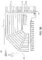
- FIG. 1Billustrates the impedance drop in the mating interface area.
- FIG. 1Bis a reflection plot of differential impedance as a function of signal propagation time through a selected differential signal pair within a connector as shown in FIG. 1A .
- Differential impedancewas measured at various times as the signal propagated through a first test board, a receptacle connector (such as described in detail below) and associated receptacle vias, the interface between the header connector and the receptacle connector, a header connector (such as described in detail below) and associated header vias, and a second test board.
- Differential impedancewas measured for a 40 ps rise time from 10%-90% of voltage level.
- the differential impedanceis about 100 ohms throughout most of the signal path.
- the nominal standardof approximately 100 ⁇
- an impedanceof about 93/94 ⁇ .
- the data shown in the plot of FIG. 1Bis within acceptable standards (because the drop is within ⁇ 8 ⁇ of the nominal impedance), there is room for improvement.
- the inventionprovides for improved performance by adjusting impedance in the mating interface area. Such an improvement may be realized by moving and/or rotating the contacts in or out of alignment. Impedance may be minimized (and capacitance maximized) by aligning the edges of the contacts. Lowering capacitance, by moving the contacts out of alignment, for example, increases impedance.
- the inventionprovides an approach for adjusting impedance, in a controlled manner, to a target impedance level.
- the inventionprovides for improved data flow through high-speed (e.g., >10 Gb/s) connectors.
- FIG. 1Ais a side view of a typical electrical connector.
- FIG. 1Bis a reflection plot of differential impedance as a function of signal propagation time.
- FIGS. 2A and 2Bdepict example embodiments of a header connector.
- FIGS. 3A and 3Bare side views of example embodiments of an insert molded leadframe assembly (IMLA).
- IMLAinsert molded leadframe assembly
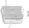
- FIGS. 4A and 4Bdepict an example embodiment of a receptacle connector.
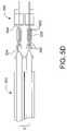
- FIGS. 5A-Ddepict engaged blade and receptacle contacts in a connector system.
- FIG. 6depicts a cross-sectional view of a contact configuration for known connectors, such as the connector shown in FIGS. 5A-5D .
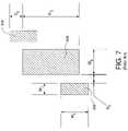
- FIG. 7is a cross-sectional view of a blade contact engaged in a receptacle contact.
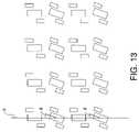
- FIGS. 8-13depict example contact configurations according to the invention for adjusting impedance characteristics of an electrical connector.
- FIGS. 2A and 2Bdepict example embodiments of a header connector.
- the header connector 200may include a plurality of insert molded leadframe assemblies (IMLAs) 202 .
- FIGS. 3A and 3Bare side views of example embodiments of an IMLA 202 according to the invention.
- An IMLA 202includes a contact set 206 of electrically conductive contacts 204 , and an IMLA frame 208 through which the contacts 204 at least partially extend.
- An IMLA 202may be used, without modification, for single-ended signaling, differential signaling, or a combination of single-ended signaling and differential signaling.
- Each contact 204may be selectively designated as a ground contact, a single-ended signal conductor, or one of a differential signal pair of signal conductors.
- the contacts designated Gmay be ground contacts, the terminal ends of which may be extended beyond the terminal ends of the other contacts. Thus, the ground contacts G may mate with complementary receptacle contacts before any of the signal contacts mates.
- the IMLAsare arranged such that contact sets 206 form contact columns, though it should be understood that the IMLAs could be arranged such that the contact sets are contact rows.
- the header connector 200is depicted with 150 contacts (i.e., 10 IMLAs with 15 contacts per IMLA), it should be understood that an IMLA may include any desired number of contacts and a connector may include any number of IMLAs. For example, IMLAs having 12 or 9 electrical contacts are also contemplated. A connector according to the invention, therefore, may include any number of contacts.
- the header connector 200includes an electrically insulating IMLA frame 208 through which the contacts extend.
- each IMLA frame 208is made of a dielectric material such as a plastic.
- the IMLA frame 208is constructed from as little material as possible. Otherwise, the connector is air-filled. That is, the contacts may be insulated from one another using air as a second dielectric. The use of air provides for a decrease in crosstalk and for a low-weight connector (as compared to a connector that uses a heavier dielectric material throughout).
- the contacts 204include terminal ends 210 for engagement with a circuit board.
- the terminal endsare compliant terminal ends, though it should be understood that the terminals ends could be press-fit or any surface-mount or through-mount terminal ends.
- the contactsalso include mating ends 212 for engagement with complementary receptacle contacts (described below in connection with FIGS. 4A and 4B ).
- FIG. 2Aa housing 214 A is preferred.
- the housing 214 Aincludes first and second walls 218 A.
- FIG. 2Bdepicts a header connector with a housing 214 B that includes a first pair of end walls 216 B and a second pair of walls 218 B.
- the header connectormay be devoid of any internal shielding. That is, the header connector may be devoid of any shield plates, for example, between adjacent contact sets. A connector according to the invention may be devoid of such internal shielding even for high-speed, high-frequency, fast rise-time signaling.
- header connector 200 depicted in FIGS. 2A and 2Bis shown as a right-angle connector, it should be understood that a connector according to the invention may be any style connector, such as a mezzanine connector, for example. That is, an appropriate header connector may be designed according to the principles of the invention for any type connector.
- FIGS. 4A and 4Bdepict an example embodiment of a receptacle connector 220 .
- the receptacle connector 220includes a plurality of receptacle contacts 224 , each of which is adapted to receive a respective mating end 212 .
- the receptacle contacts 224are in an arrangement that is complementary to the arrangement of the mating ends 212 .
- the mating ends 212may be received by the receptacle contacts 224 upon mating of the assemblies.
- the receptacle contacts 224are arranged to form contact sets 226 .
- the receptacle connector 220is depicted with 150 contacts (i.e., 15 contacts per column), it should be understood that a connector according to the invention may include any number of contacts.
- Each receptacle contact 224has a mating end 230 , for receiving a mating end 212 of a complementary header contact 204 , and a terminal end 232 for engagement with a circuit board.
- the terminal ends 232are compliant terminal ends, though it should be understood that the terminals ends could be press-fit, balls, or any surface-mount or through-mount terminal ends.
- a housing 234is also preferably provided to position and retain the IMLAs relative to one another.
- the receptacle connectormay also be devoid of any internal shielding. That is, the receptacle connector may be devoid of any shield plates, for example, between adjacent contact sets.
- FIGS. 5A-Ddepict engaged blade and receptacle contacts in a connector system.
- FIG. 5Ais a side view of a mated connector system including engaged blade contacts 504 and receptacle contacts 524 .
- the connector systemmay include a header connector 500 that includes one or more blade contacts 504 , and a receptacle connector 520 that includes one or more receptacle contacts 524 .
- FIG. 5Bis a partial, detailed view of the connector system shown in FIG. 5A .
- Each of a plurality of blade contacts 504may engage a respective one of a plurality of receptacle contacts 524 .
- blade contacts 504may be disposed along, and extend through, an IMLA in the header connector 500 .
- Receptacle contacts 524may be disposed along, and extend through, an IMLA in the receptacle connector 520 .
- Contacts 504may extend through respective air regions 508 and be separated from one another in the air region 508 by a distance D.
- FIG. 5Cis a partial top view of engaged blade and receptacle contacts in adjacent IMLAs.
- FIG. 5Dis a partial detail view of the engaged blade and receptacle contacts shown in FIG. 5C .
- Either or both of the contactsmay be signal contacts or ground contacts, and the pair of contacts may form a differential signal pair.
- Either or both of the contactsmay be single-ended signal conductors.
- Each blade contact 504extends through a respective IMLA 506 . Contacts 504 in adjacent IMLAs may be separated from one another by a distance D′. Blade contacts 504 may be received in respective receptacle contacts 524 to provide electrical connection between the blade contacts 504 and respective receptacle contacts 524 . As shown, a terminal portion 836 of blade contact 504 may be received by a pair of beam portions 839 of a receptacle contact 524 . Each beam portion 839 may include a contact interface portion 841 that makes electrical contact with the terminal portion 836 of the blade contact 504 . Preferably, the beam portions 839 are sized and shaped to provide contact between the blades 836 and the contact interfaces 841 over a combined surface area that is sufficient to maintain the electrical characteristics of the connector during mating and unmating of the connector.
- FIG. 6depicts a cross-sectional view of a contact configuration for known connectors, such as the connector shown in FIGS. 5A-5D .
- terminal blades 836 of the blade contactsare received into beam portions 839 of the receptacle contacts.
- the contact configuration shown in FIG. 6allows the edge-coupled aspect ratio to be maintained in the mating region. That is, the aspect ratio of column pitch to gap width may be chosen to limit cross talk in the connector exists in the contact region as well, and thereby limits cross talk in the mating region. Also, because the cross-section of the unmated blade contact is nearly the same as the combined cross-section of the mated contacts, the impedance profile can be maintained even if the connector is partially unmated.
- the combined cross-section of the mated contactsincludes no more than one or two thickness of metal (the thicknesses of the blade and the contact interface), rather than three thicknesses as would be typical in prior art connectors.
- mating or unmatingresults in a significant change in cross-section, and therefore, a significant change in impedance (which may cause significant degradation of electrical performance if the connector is not properly and completely mated).
- the contact cross-sectiondoes not change dramatically as the connector is unmated, the connector can provide nearly the same electrical characteristics when partially unmated (e.g., unmated by about 1-2 mm) as it does when fully mated.
- the contactsare arranged in contact columns set a distance d 1 apart.
- the column pitchi.e., distance between adjacent contact columns
- d 2the distance between the contact centers of adjacent contacts in a given row
- d 2the distance between the contact centers of adjacent contacts in a given column
- d 1 and d 2may be any appropriate distance.
- the differential impedance for the contact configuration of FIG. 6may be approximately 109.0 ⁇ .
- FIG. 7is a detailed cross-sectional view of a blade contact 836 engaged in a receptacle contact 841 in a configuration as depicted in FIG. 6 .
- the width W 2 and height H 2 of terminal blade 836may be approximately 2.1 mm and 4.5 mm, respectively.
- the width W 1 and height H 1 of contact interfaces 841may be approximately 1.14 mm and 2.47 mm, respectively.
- the spacing S 1 between contact interfaces 841 and terminal blade 836may be approximately 0.65 mm.
- Contact interfaces 841are offset from terminal blade 836 by a distance S 2 , which may be approximately 0.77 mm, for example.
- a contact configuration such as that depicted in FIG. 8increases the impedance characteristics of such a connector by approximately 6.0 ⁇ . That is, the differential impedance of a connector with a contact configuration as shown in FIG. 8 (with contact dimensions that are approximately the same as those shown in FIG. 7 ) is approximately 115.0 ⁇ .
- Such a contact configurationhelps elevate the impedance in the header/receptacle interface area of the connector by interrupting the edge coupling between adjacent contacts.
- FIG. 8depicts a contact configuration wherein adjacent contacts in a contact set are staggered relative to one another.
- the contact setextends generally along a first direction (e.g., a contact column).
- Adjacent contactsare staggered relative to one another in a second direction relative to the centerline a of the contact set (i.e., in a direction perpendicular to the direction along which the contact set extends).
- the contact rowsmay be staggered relative to one another by an offset o 1 , with each contact center being offset from the centerline a by about o 1 /2.
- Impedance dropmay be minimized by aligning the edges of the contacts, that is, staggering the contacts by an offset equal to the contact thickness t.
- tmay be approximately 2.1 mm.
- the contactsare arranged such that each contact column is disposed in a respective IMLA. Accordingly, the contacts may be made to jog away from a contact column centerline a (which may or may not be collinear with the centerline of the IMLA).
- the contactsare “misaligned,” as shown in FIG. 8 , only in the mating interface region. That is, the contacts preferably extend through the connector such that the terminal ends that mate with a board or another connector are not misaligned.
- FIG. 9depicts a contact configuration wherein adjacent contacts 900 a and 900 b in a contact set are twisted or rotated in the mating interface region. Twisting or rotating the contact in the mating interface region may reduce differential impedance of a connector. Such reduction may be desirable when matching impedance of a device to a connector to prevent signal reflection, a problem that may be magnified at higher data rates.
- the contact setextends generally along a first direction (e.g., along centerline a, such that centerline a extends through a center of each contact, as shown), thus forming a contact column, for example, as shown, or a contact row.
- Each contact 900 a and 900 bmay be rotated or twisted relative to the centerline a of the contact set such that, in the mating interface region, it forms a respective angle ⁇ with the contact column centerline a.
- the angle ⁇may be approximately 10°.
- the angle ⁇may be any non-zero and non-180 degree angle. Impedance may be reduced by rotating each contact 900 a and 900 b , as shown, such that adjacent contacts 900 a and 900 b are rotated in opposing directions and all contacts 900 a and 900 b form the same (absolute) angle with the centerline.
- the differential impedance in a connector with such a configurationmay be approximately 108.7 ⁇ , or 0.3 ⁇ less than a connector in which the contacts are not rotated, such as shown in FIG. 6 . It should be understood, however, that the angle to which the contacts 900 a and 900 b are rotated may be chosen to achieve a desired impedance level. Further, though the angles depicted in FIG. 9 are the same for all contacts 900 a and 900 b , it should be understood that the angles could be chosen independently for each contact 900 a and 900 b.
- the contactsare arranged such that each contact column is disposed in a respective IMLA.
- the contactsare rotated or twisted only in the mating interface region. That is, the contacts preferably extend through the connector such that the terminal ends that mate with a board or another connector are not rotated.
- FIG. 10depicts a contact configuration wherein adjacent contacts in a contact set are twisted or rotated in the mating interface region.
- each set of contacts depicted in FIG. 10is shown twisted or rotated in the same direction relative to the centerline a of the contact set.
- Such a configurationmay lower impedance more than the configuration of FIG. 9 , offering an alternative way that connector impedance may be fine-tuned to match an impedance of a device.
- each contact setextends generally along a first direction (e.g., along centerline a, as shown), thus forming a contact column, for example, as shown, or a contact row.
- Each contactmay be rotated or twisted such that it forms a respective angle ⁇ with the contact column centerline a in the mating interface region.
- the angle ⁇may be approximately 10°.
- the differential impedance in a connector with such a configurationmay be approximately 104.2 ⁇ , or 4.8 ⁇ less than in a connector in which the contacts are not rotated, as shown in FIG. 6 , and approximately 4.5 ⁇ less than a connector in which adjacent contacts are rotated in opposing directions, as shown in FIG. 9 .
- the angle to which the contacts are rotatedmay be chosen to achieve a desired impedance level. Further, though the angles depicted in FIG. 10 are the same for all contacts, it should be understood that the angles could be chosen independently for each contact. Also, though the contacts in adjacent contact columns are depicted as being rotated in opposite directions relative to their respective centerlines, it should be understood that adjacent contact sets may be rotated in the same or different directions relative to their respective centerlines a.
- FIG. 11depicts a contact configuration wherein adjacent contacts within a set are rotated in opposite directions and are staggered relative to one another.
- Each contact setmay extend generally along a first direction (e.g., along centerline a, as shown), thus forming a contact column, for example, as shown, or a contact row.
- adjacent contactsmay be staggered relative to one another in a second direction (e.g., in the direction perpendicular to the direction along which the contact set extends).
- adjacent contactsmay be staggered relative to one another by an offset o 1 .
- the offset o 1may be equal to the contact thickness t, which may be approximately 2.1 mm, for example.
- each contactmay be rotated or twisted in the mating interface region such that it forms a respective angle ⁇ with the contact column centerline.
- Adjacent contactsmay be rotated in opposing directions, and all contacts form the same (absolute) angle with the centerline, which may be 10°, for example.
- the differential impedance in a connector with such a configurationmay be approximately 114.8 ⁇ .
- FIG. 12depicts a contact configuration in which the contacts have been both rotated and staggered relative to one another.
- Each contact setmay extend generally along a first direction (e.g., along centerline a, as shown), thus forming a contact column, for example, as shown, or a contact row.
- Adjacent contacts within a columnmay be rotated in the same direction relative to the centerline a of their respective columns.
- adjacent contactsmay be staggered relative to one another in a second direction (e.g., in the direction perpendicular to the direction along which the contact set extends).
- contact rowsmay be staggered relative to one another by an offset o 1 , which may be, for example, equal to the contact thickness t.
- contact thickness tmay be approximately 2.1 mm.
- Each contactmay also be rotated or twisted such that it forms a respective angle with the contact column centerline in the mating interface region.
- the angle of rotation ⁇may be approximately 10°.
- the differential impedance in the connectormay vary between contact pairs.
- contact pair Amay have a differential impedance of 110.8 ⁇
- contact pair Bmay have a differential impedance of 118.3 ⁇ .
- the varying impedance between contact pairsmay be attributable to the orientation of the contacts in the contact pairs.
- the twisting of the contactsmay reduce the effects of the offset because the contacts largely remain edge-coupled. That is, edges e of the contacts in contact pair A remain facing each other.
- edges f of the contacts of contact pair Bmay be such that edge coupling is limited.
- the twisting of the contacts in addition to the offsetmay reduce the edge coupling more than would be the case if staggering the contacts without twisting.
- alternating contacts in a columnmay be rotated to form an angle of ⁇ with a centerline a of the contact column.
- the remaining contacts in the columnmay be positioned at 0° to the centerline a.
- the inventionprovides an approach for adjusting impedance and capacitance, in a controlled manner, to a target level.
Landscapes
- Details Of Connecting Devices For Male And Female Coupling (AREA)
- Coupling Device And Connection With Printed Circuit (AREA)
Abstract
Description
Claims (16)
Priority Applications (3)
| Application Number | Priority Date | Filing Date | Title |
|---|---|---|---|
| US10/946,874US7517250B2 (en) | 2003-09-26 | 2004-09-22 | Impedance mating interface for electrical connectors |
| US11/229,778US7524209B2 (en) | 2003-09-26 | 2005-09-19 | Impedance mating interface for electrical connectors |
| US12/420,439US7837504B2 (en) | 2003-09-26 | 2009-04-08 | Impedance mating interface for electrical connectors |
Applications Claiming Priority (2)
| Application Number | Priority Date | Filing Date | Title |
|---|---|---|---|
| US50642703P | 2003-09-26 | 2003-09-26 | |
| US10/946,874US7517250B2 (en) | 2003-09-26 | 2004-09-22 | Impedance mating interface for electrical connectors |
Related Child Applications (1)
| Application Number | Title | Priority Date | Filing Date |
|---|---|---|---|
| US11/229,778Continuation-In-PartUS7524209B2 (en) | 2003-09-26 | 2005-09-19 | Impedance mating interface for electrical connectors |
Publications (2)
| Publication Number | Publication Date |
|---|---|
| US20050148239A1 US20050148239A1 (en) | 2005-07-07 |
| US7517250B2true US7517250B2 (en) | 2009-04-14 |
Family
ID=34393152
Family Applications (1)
| Application Number | Title | Priority Date | Filing Date |
|---|---|---|---|
| US10/946,874Expired - LifetimeUS7517250B2 (en) | 2003-09-26 | 2004-09-22 | Impedance mating interface for electrical connectors |
Country Status (2)
| Country | Link |
|---|---|
| US (1) | US7517250B2 (en) |
| WO (1) | WO2005031922A2 (en) |
Cited By (5)
| Publication number | Priority date | Publication date | Assignee | Title |
|---|---|---|---|---|
| US20100197149A1 (en)* | 2009-02-02 | 2010-08-05 | Tyco Electronics Corporation | High density connector assembly |
| US20140111960A1 (en)* | 2012-10-23 | 2014-04-24 | Tyco Electronics Corporation | Leadframe module for an electrical connector |
| US8727791B2 (en)* | 2008-01-17 | 2014-05-20 | Amphenol Corporation | Electrical connector assembly |
| US8784116B2 (en) | 2011-04-04 | 2014-07-22 | Fci Americas Technology Llc | Electrical connector |
| US9017114B2 (en) | 2009-09-09 | 2015-04-28 | Amphenol Corporation | Mating contacts for high speed electrical connectors |
Families Citing this family (33)
| Publication number | Priority date | Publication date | Assignee | Title |
|---|---|---|---|---|
| US7524209B2 (en)* | 2003-09-26 | 2009-04-28 | Fci Americas Technology, Inc. | Impedance mating interface for electrical connectors |
| US7137832B2 (en)* | 2004-06-10 | 2006-11-21 | Samtec Incorporated | Array connector having improved electrical characteristics and increased signal pins with decreased ground pins |
| US7108556B2 (en) | 2004-07-01 | 2006-09-19 | Amphenol Corporation | Midplane especially applicable to an orthogonal architecture electronic system |
| US8444436B1 (en) | 2004-07-01 | 2013-05-21 | Amphenol Corporation | Midplane especially applicable to an orthogonal architecture electronic system |
| US7094102B2 (en)* | 2004-07-01 | 2006-08-22 | Amphenol Corporation | Differential electrical connector assembly |
| US20090291593A1 (en) | 2005-06-30 | 2009-11-26 | Prescott Atkinson | High frequency broadside-coupled electrical connector |
| US7914304B2 (en)* | 2005-06-30 | 2011-03-29 | Amphenol Corporation | Electrical connector with conductors having diverging portions |
| US7331802B2 (en)* | 2005-11-02 | 2008-02-19 | Tyco Electronics Corporation | Orthogonal connector |
| US7497736B2 (en)* | 2006-12-19 | 2009-03-03 | Fci Americas Technology, Inc. | Shieldless, high-speed, low-cross-talk electrical connector |
| US8764464B2 (en) | 2008-02-29 | 2014-07-01 | Fci Americas Technology Llc | Cross talk reduction for high speed electrical connectors |
| US7758385B2 (en)* | 2008-03-07 | 2010-07-20 | Tyco Electronics Corporation | Orthogonal electrical connector and assembly |
| US7988456B2 (en)* | 2009-01-14 | 2011-08-02 | Tyco Electronics Corporation | Orthogonal connector system |
| US9277649B2 (en) | 2009-02-26 | 2016-03-01 | Fci Americas Technology Llc | Cross talk reduction for high-speed electrical connectors |
| US8079847B2 (en)* | 2009-06-01 | 2011-12-20 | Tyco Electronics Corporation | Orthogonal connector system with power connection |
| US8267721B2 (en) | 2009-10-28 | 2012-09-18 | Fci Americas Technology Llc | Electrical connector having ground plates and ground coupling bar |
| US8616919B2 (en) | 2009-11-13 | 2013-12-31 | Fci Americas Technology Llc | Attachment system for electrical connector |
| CN107069274B (en) | 2010-05-07 | 2020-08-18 | 安费诺有限公司 | High performance cable connector |
| US8734187B2 (en) | 2010-06-28 | 2014-05-27 | Fci | Electrical connector with ground plates |
| TWM449270U (en) | 2010-12-21 | 2013-03-21 | Framatome Connectors Int | Electrical assembly |
| WO2012106554A2 (en) | 2011-02-02 | 2012-08-09 | Amphenol Corporation | Mezzanine connector |
| US9240644B2 (en) | 2012-08-22 | 2016-01-19 | Amphenol Corporation | High-frequency electrical connector |
| CN115411547A (en) | 2014-01-22 | 2022-11-29 | 安费诺有限公司 | Electrical connector, subassembly, module, cable assembly, electrical assembly and circuit board |
| CN108701922B (en) | 2015-07-07 | 2020-02-14 | Afci亚洲私人有限公司 | Electrical connector |
| CN110632717A (en)* | 2015-09-10 | 2019-12-31 | 申泰公司 | Rack mount equipment with high heat dissipation modules and transceiver sockets with increased cooling |
| CN112151987B (en) | 2016-08-23 | 2022-12-30 | 安费诺有限公司 | Configurable high performance connector |
| CN208862209U (en) | 2018-09-26 | 2019-05-14 | 安费诺东亚电子科技(深圳)有限公司 | A connector and its applied PCB board |
| JP7039435B2 (en)* | 2018-10-05 | 2022-03-22 | モレックス エルエルシー | Connector assembly |
| CN111585098B (en) | 2019-02-19 | 2025-08-19 | 安费诺有限公司 | High-speed connector |
| TWI887339B (en) | 2020-01-27 | 2025-06-21 | 美商Fci美國有限責任公司 | High speed, high density direct mate orthogonal connector |
| WO2021154702A1 (en) | 2020-01-27 | 2021-08-05 | Fci Usa Llc | High speed connector |
| CN215816516U (en) | 2020-09-22 | 2022-02-11 | 安费诺商用电子产品(成都)有限公司 | Electrical connector |
| CN213636403U (en) | 2020-09-25 | 2021-07-06 | 安费诺商用电子产品(成都)有限公司 | Electrical connector |
| CN215266741U (en) | 2021-08-13 | 2021-12-21 | 安费诺商用电子产品(成都)有限公司 | High-performance card connector meeting high-bandwidth transmission |
Citations (134)
| Publication number | Priority date | Publication date | Assignee | Title |
|---|---|---|---|---|
| US3286220A (en) | 1964-06-10 | 1966-11-15 | Amp Inc | Electrical connector means |
| US3538486A (en) | 1967-05-25 | 1970-11-03 | Amp Inc | Connector device with clamping contact means |
| US3669054A (en) | 1970-03-23 | 1972-06-13 | Amp Inc | Method of manufacturing electrical terminals |
| US3748633A (en) | 1972-01-24 | 1973-07-24 | Amp Inc | Square post connector |
| US4076362A (en) | 1976-02-20 | 1978-02-28 | Japan Aviation Electronics Industry Ltd. | Contact driver |
| US4159861A (en) | 1977-12-30 | 1979-07-03 | International Telephone And Telegraph Corporation | Zero insertion force connector |
| US4260212A (en) | 1979-03-20 | 1981-04-07 | Amp Incorporated | Method of producing insulated terminals |
| US4288139A (en) | 1979-03-06 | 1981-09-08 | Amp Incorporated | Trifurcated card edge terminal |
| US4383724A (en) | 1980-06-03 | 1983-05-17 | E. I. Du Pont De Nemours And Company | Bridge connector for electrically connecting two pins |
| US4402563A (en) | 1981-05-26 | 1983-09-06 | Aries Electronics, Inc. | Zero insertion force connector |
| US4560222A (en) | 1984-05-17 | 1985-12-24 | Molex Incorporated | Drawer connector |
| US4717360A (en) | 1986-03-17 | 1988-01-05 | Zenith Electronics Corporation | Modular electrical connector |
| EP0273683A2 (en) | 1986-12-26 | 1988-07-06 | Fujitsu Limited | An electrical connector |
| US4776803A (en) | 1986-11-26 | 1988-10-11 | Minnesota Mining And Manufacturing Company | Integrally molded card edge cable termination assembly, contact, machine and method |
| US4867713A (en) | 1987-02-24 | 1989-09-19 | Kabushiki Kaisha Toshiba | Electrical connector |
| US4907990A (en) | 1988-10-07 | 1990-03-13 | Molex Incorporated | Elastically supported dual cantilever beam pin-receiving electrical contact |
| US4913664A (en) | 1988-11-25 | 1990-04-03 | Molex Incorporated | Miniature circular DIN connector |
| US4973271A (en) | 1989-01-30 | 1990-11-27 | Yazaki Corporation | Low insertion-force terminal |
| US5066236A (en) | 1989-10-10 | 1991-11-19 | Amp Incorporated | Impedance matched backplane connector |
| US5077893A (en) | 1989-09-26 | 1992-01-07 | Molex Incorporated | Method for forming electrical terminal |
| US5163849A (en) | 1991-08-27 | 1992-11-17 | Amp Incorporated | Lead frame and electrical connector |
| US5174770A (en)* | 1990-11-15 | 1992-12-29 | Amp Incorporated | Multicontact connector for signal transmission |
| US5192231A (en) | 1990-06-19 | 1993-03-09 | Echelon Corporation | Power line communications coupler |
| US5238414A (en) | 1991-07-24 | 1993-08-24 | Hirose Electric Co., Ltd. | High-speed transmission electrical connector |
| US5254012A (en) | 1992-08-21 | 1993-10-19 | Industrial Technology Research Institute | Zero insertion force socket |
| US5274918A (en) | 1993-04-15 | 1994-01-04 | The Whitaker Corporation | Method for producing contact shorting bar insert for modular jack assembly |
| US5277624A (en) | 1991-12-23 | 1994-01-11 | Souriau Et Cie | Modular electrical-connection element |
| US5286212A (en) | 1992-03-09 | 1994-02-15 | The Whitaker Corporation | Shielded back plane connector |
| US5302135A (en) | 1993-02-09 | 1994-04-12 | Lee Feng Jui | Electrical plug |
| JPH06236788A (en) | 1993-01-12 | 1994-08-23 | Japan Aviation Electron Ind Ltd | Socket |
| US5342211A (en) | 1992-03-09 | 1994-08-30 | The Whitaker Corporation | Shielded back plane connector |
| US5356301A (en) | 1991-12-23 | 1994-10-18 | Framatome Connectors International | Modular electrical-connection element |
| US5357050A (en) | 1992-11-20 | 1994-10-18 | Ast Research, Inc. | Apparatus and method to reduce electromagnetic emissions in a multi-layer circuit board |
| US5356300A (en) | 1993-09-16 | 1994-10-18 | The Whitaker Corporation | Blind mating guides with ground contacts |
| US5431578A (en) | 1994-03-02 | 1995-07-11 | Abrams Electronics, Inc. | Compression mating electrical connector |
| JPH07114958B2 (en) | 1990-01-19 | 1995-12-13 | 住友金属鉱山株式会社 | High temperature combustion catalyst carrier |
| US5475922A (en) | 1992-12-18 | 1995-12-19 | Fujitsu Ltd. | Method of assembling a connector using frangible contact parts |
| US5558542A (en) | 1995-09-08 | 1996-09-24 | Molex Incorporated | Electrical connector with improved terminal-receiving passage means |
| US5586914A (en) | 1995-05-19 | 1996-12-24 | The Whitaker Corporation | Electrical connector and an associated method for compensating for crosstalk between a plurality of conductors |
| US5590463A (en) | 1995-07-18 | 1997-01-07 | Elco Corporation | Circuit board connectors |
| US5609502A (en) | 1995-03-31 | 1997-03-11 | The Whitaker Corporation | Contact retention system |
| US5713746A (en) | 1994-02-08 | 1998-02-03 | Berg Technology, Inc. | Electrical connector |
| US5730609A (en) | 1995-04-28 | 1998-03-24 | Molex Incorporated | High performance card edge connector |
| US5741161A (en) | 1996-01-04 | 1998-04-21 | Pcd Inc. | Electrical connection system with discrete wire interconnections |
| US5741144A (en) | 1995-06-12 | 1998-04-21 | Berg Technology, Inc. | Low cross and impedance controlled electric connector |
| US5795191A (en) | 1996-09-11 | 1998-08-18 | Preputnick; George | Connector assembly with shielded modules and method of making same |
| US5817973A (en) | 1995-06-12 | 1998-10-06 | Berg Technology, Inc. | Low cross talk and impedance controlled electrical cable assembly |
| US5853797A (en) | 1995-11-20 | 1998-12-29 | Lucent Technologies, Inc. | Method of providing corrosion protection |
| US5908333A (en) | 1997-07-21 | 1999-06-01 | Rambus, Inc. | Connector with integral transmission line bus |
| US5925274A (en) | 1996-07-11 | 1999-07-20 | Mckinney; Duane M. | Electrical range power override timer unit |
| US5961355A (en)* | 1997-12-17 | 1999-10-05 | Berg Technology, Inc. | High density interstitial connector system |
| US5967844A (en) | 1995-04-04 | 1999-10-19 | Berg Technology, Inc. | Electrically enhanced modular connector for printed wiring board |
| US5971817A (en) | 1995-09-27 | 1999-10-26 | Siemens Aktiengesellschaft | Contact spring for a plug-in connector |
| US5980321A (en) | 1997-02-07 | 1999-11-09 | Teradyne, Inc. | High speed, high density electrical connector |
| US5993259A (en) | 1997-02-07 | 1999-11-30 | Teradyne, Inc. | High speed, high density electrical connector |
| JP2000003744A (en) | 1998-06-15 | 2000-01-07 | Honda Tsushin Kogyo Co Ltd | Printed circuit board connector |
| JP2000003746A (en) | 1998-06-15 | 2000-01-07 | Honda Tsushin Kogyo Co Ltd | Printed circuit board connector |
| JP2000003745A (en) | 1998-06-15 | 2000-01-07 | Honda Tsushin Kogyo Co Ltd | Printed circuit board connector |
| JP2000003743A (en) | 1998-06-15 | 2000-01-07 | Honda Tsushin Kogyo Co Ltd | Printed circuit board connector |
| US6050862A (en) | 1997-05-20 | 2000-04-18 | Yazaki Corporation | Female terminal with flexible contact area having inclined free edge portion |
| US6068520A (en) | 1997-03-13 | 2000-05-30 | Berg Technology, Inc. | Low profile double deck connector with improved cross talk isolation |
| US6116926A (en) | 1999-04-21 | 2000-09-12 | Berg Technology, Inc. | Connector for electrical isolation in a condensed area |
| US6116965A (en) | 1998-02-27 | 2000-09-12 | Lucent Technologies Inc. | Low crosstalk connector configuration |
| US6123554A (en) | 1999-05-28 | 2000-09-26 | Berg Technology, Inc. | Connector cover with board stiffener |
| US6125535A (en) | 1998-12-31 | 2000-10-03 | Hon Hai Precision Ind. Co., Ltd. | Method for insert molding a contact module |
| US6129592A (en) | 1997-11-04 | 2000-10-10 | The Whitaker Corporation | Connector assembly having terminal modules |
| US6139336A (en) | 1996-11-14 | 2000-10-31 | Berg Technology, Inc. | High density connector having a ball type of contact surface |
| US6146157A (en) | 1997-07-08 | 2000-11-14 | Framatome Connectors International | Connector assembly for printed circuit boards |
| US6171115B1 (en) | 2000-02-03 | 2001-01-09 | Tyco Electronics Corporation | Electrical connector having circuit boards and keying for different types of circuit boards |
| US6171149B1 (en) | 1998-12-28 | 2001-01-09 | Berg Technology, Inc. | High speed connector and method of making same |
| US6190213B1 (en) | 1998-01-07 | 2001-02-20 | Amphenol-Tuchel Electronics Gmbh | Contact element support in particular for a thin smart card connector |
| US6212755B1 (en) | 1997-09-19 | 2001-04-10 | Murata Manufacturing Co., Ltd. | Method for manufacturing insert-resin-molded product |
| US6220896B1 (en) | 1999-05-13 | 2001-04-24 | Berg Technology, Inc. | Shielded header |
| US6219913B1 (en) | 1997-01-13 | 2001-04-24 | Sumitomo Wiring Systems, Ltd. | Connector producing method and a connector produced by insert molding |
| WO2001029931A1 (en) | 1999-10-18 | 2001-04-26 | Erni Elektroapparate Gmbh | Shielded plug-in connector |
| US6227882B1 (en) | 1997-10-01 | 2001-05-08 | Berg Technology, Inc. | Connector for electrical isolation in a condensed area |
| WO2001039332A1 (en) | 1999-11-24 | 2001-05-31 | Teradyne, Inc. | Differential signal electrical connectors |
| US6267604B1 (en) | 2000-02-03 | 2001-07-31 | Tyco Electronics Corporation | Electrical connector including a housing that holds parallel circuit boards |
| US6269539B1 (en) | 1996-06-25 | 2001-08-07 | Fujitsu Takamisawa Component Limited | Fabrication method of connector having internal switch |
| US6280209B1 (en) | 1999-07-16 | 2001-08-28 | Molex Incorporated | Connector with improved performance characteristics |
| US6293827B1 (en) | 2000-02-03 | 2001-09-25 | Teradyne, Inc. | Differential signal electrical connector |
| US6319075B1 (en) | 1998-04-17 | 2001-11-20 | Fci Americas Technology, Inc. | Power connector |
| US6328602B1 (en) | 1999-06-17 | 2001-12-11 | Nec Corporation | Connector with less crosstalk |
| US6343955B2 (en) | 2000-03-29 | 2002-02-05 | Berg Technology, Inc. | Electrical connector with grounding system |
| US6347952B1 (en) | 1999-10-01 | 2002-02-19 | Sumitomo Wiring Systems, Ltd. | Connector with locking member and audible indication of complete locking |
| US6350134B1 (en) | 2000-07-25 | 2002-02-26 | Tyco Electronics Corporation | Electrical connector having triad contact groups arranged in an alternating inverted sequence |
| US6354877B1 (en) | 1996-08-20 | 2002-03-12 | Fci Americas Technology, Inc. | High speed modular electrical connector and receptacle for use therein |
| US6358061B1 (en) | 1999-11-09 | 2002-03-19 | Molex Incorporated | High-speed connector with shorting capability |
| US6361366B1 (en) | 1997-08-20 | 2002-03-26 | Fci Americas Technology, Inc. | High speed modular electrical connector and receptacle for use therein |
| US6363607B1 (en) | 1998-12-24 | 2002-04-02 | Hon Hai Precision Ind. Co., Ltd. | Method for manufacturing a high density connector |
| US6371773B1 (en)* | 2000-03-23 | 2002-04-16 | Ohio Associated Enterprises, Inc. | High density interconnect system and method |
| US6375478B1 (en) | 1999-06-18 | 2002-04-23 | Nec Corporation | Connector well fit with printed circuit board |
| US6386914B1 (en) | 2001-03-26 | 2002-05-14 | Amphenol Corporation | Electrical connector having mixed grounded and non-grounded contacts |
| US6409543B1 (en) | 2001-01-25 | 2002-06-25 | Teradyne, Inc. | Connector molding method and shielded waferized connector made therefrom |
| US20020106930A1 (en) | 2001-02-05 | 2002-08-08 | Harting Kgaa | Contact assembly for a plug connector, in particular for a PCB plug connector |
| US6431914B1 (en) | 2001-06-04 | 2002-08-13 | Hon Hai Precision Ind. Co., Ltd. | Grounding scheme for a high speed backplane connector system |
| US6435914B1 (en) | 2001-06-27 | 2002-08-20 | Hon Hai Precision Ind. Co., Ltd. | Electrical connector having improved shielding means |
| US6461202B2 (en) | 2001-01-30 | 2002-10-08 | Tyco Electronics Corporation | Terminal module having open side for enhanced electrical performance |
| US6482038B2 (en) | 2001-02-23 | 2002-11-19 | Fci Americas Technology, Inc. | Header assembly for mounting to a circuit substrate |
| US6485330B1 (en) | 1998-05-15 | 2002-11-26 | Fci Americas Technology, Inc. | Shroud retention wafer |
| US6506081B2 (en) | 2001-05-31 | 2003-01-14 | Tyco Electronics Corporation | Floatable connector assembly with a staggered overlapping contact pattern |
| US6520803B1 (en) | 2002-01-22 | 2003-02-18 | Fci Americas Technology, Inc. | Connection of shields in an electrical connector |
| US6527587B1 (en) | 1999-04-29 | 2003-03-04 | Fci Americas Technology, Inc. | Header assembly for mounting to a circuit substrate and having ground shields therewithin |
| US6537111B2 (en) | 2000-05-31 | 2003-03-25 | Wabco Gmbh And Co. Ohg | Electric contact plug with deformable attributes |
| US6540559B1 (en) | 2001-09-28 | 2003-04-01 | Tyco Electronics Corporation | Connector with staggered contact pattern |
| US6547066B2 (en) | 2001-08-31 | 2003-04-15 | Labelwhiz.Com, Inc. | Compact disk storage systems |
| US6572410B1 (en) | 2002-02-20 | 2003-06-03 | Fci Americas Technology, Inc. | Connection header and shield |
| US20030143894A1 (en) | 2002-01-28 | 2003-07-31 | Kline Richard S. | Connector assembly interface for L-shaped ground shields and differential contact pairs |
| US6652318B1 (en) | 2002-05-24 | 2003-11-25 | Fci Americas Technology, Inc. | Cross-talk canceling technique for high speed electrical connectors |
| US20030220021A1 (en) | 2002-05-22 | 2003-11-27 | Whiteman Robert Neil | High speed electrical connector |
| US6672907B2 (en)* | 2000-05-02 | 2004-01-06 | Fci Americas Technology, Inc. | Connector |
| US6692272B2 (en) | 2001-11-14 | 2004-02-17 | Fci Americas Technology, Inc. | High speed electrical connector |
| US6695627B2 (en) | 2001-08-02 | 2004-02-24 | Fci Americas Technnology, Inc. | Profiled header ground pin |
| US6762067B1 (en) | 2000-01-18 | 2004-07-13 | Fairchild Semiconductor Corporation | Method of packaging a plurality of devices utilizing a plurality of lead frames coupled together by rails |
| US6764341B2 (en)* | 2001-05-25 | 2004-07-20 | Erni Elektroapparate Gmbh | Plug connector that can be turned by 90° |
| US6805278B1 (en) | 1999-10-19 | 2004-10-19 | Fci America Technology, Inc. | Self-centering connector with hold down |
| US6808399B2 (en) | 2002-12-02 | 2004-10-26 | Tyco Electronics Corporation | Electrical connector with wafers having split ground planes |
| US6824391B2 (en) | 2000-02-03 | 2004-11-30 | Tyco Electronics Corporation | Electrical connector having customizable circuit board wafers |
| US20050009402A1 (en) | 2003-07-11 | 2005-01-13 | Chih-Ming Chien | Electrical connector with double mating interfaces for electronic components |
| US6848944B2 (en) | 2001-11-12 | 2005-02-01 | Fci Americas Technology, Inc. | Connector for high-speed communications |
| US6852567B1 (en) | 1999-05-31 | 2005-02-08 | Infineon Technologies A.G. | Method of assembling a semiconductor device package |
| EP1148587B1 (en) | 1996-07-17 | 2005-04-13 | Minnesota Mining And Manufacturing Company | Electrical interconnection system and device |
| US6890214B2 (en) | 2002-08-21 | 2005-05-10 | Tyco Electronics Corporation | Multi-sequenced contacts from single lead frame |
| US6932649B1 (en) | 2004-03-19 | 2005-08-23 | Tyco Electronics Corporation | Active wafer for improved gigabit signal recovery, in a serial point-to-point architecture |
| US6945796B2 (en) | 1999-07-16 | 2005-09-20 | Molex Incorporated | Impedance-tuned connector |
| US6953351B2 (en) | 2002-06-21 | 2005-10-11 | Molex Incorporated | High-density, impedance-tuned connector having modular construction |
| US6976886B2 (en) | 2001-11-14 | 2005-12-20 | Fci Americas Technology, Inc. | Cross talk reduction and impedance-matching for high speed electrical connectors |
| US20060014433A1 (en) | 2004-07-14 | 2006-01-19 | Consoli John J | Electrical connector with ESD protection |
| US6994569B2 (en) | 2001-11-14 | 2006-02-07 | Fci America Technology, Inc. | Electrical connectors having contacts that may be selectively designated as either signal or ground contacts |
| US20060046526A1 (en) | 2004-08-31 | 2006-03-02 | Minich Steven E | Contact protector for electrical connectors |
| WO2006031296A2 (en) | 2004-09-14 | 2006-03-23 | Fci Americas Technology, Inc. | Ball grid array connector |
| US7097506B2 (en) | 2002-10-15 | 2006-08-29 | Japan Aviation Electronics Industry Limited | Contact module in which mounting of contacts is simplified |
| US20060192274A1 (en) | 2004-11-12 | 2006-08-31 | Chippac, Inc | Semiconductor package having double layer leadframe |
| US7131870B2 (en) | 2005-02-07 | 2006-11-07 | Tyco Electronics Corporation | Electrical connector |
Family Cites Families (1)
| Publication number | Priority date | Publication date | Assignee | Title |
|---|---|---|---|---|
| US6530790B1 (en)* | 1998-11-24 | 2003-03-11 | Teradyne, Inc. | Electrical connector |
- 2004
- 2004-09-22WOPCT/US2004/030925patent/WO2005031922A2/enactiveApplication Filing
- 2004-09-22USUS10/946,874patent/US7517250B2/ennot_activeExpired - Lifetime
Patent Citations (149)
| Publication number | Priority date | Publication date | Assignee | Title |
|---|---|---|---|---|
| US3286220A (en) | 1964-06-10 | 1966-11-15 | Amp Inc | Electrical connector means |
| US3538486A (en) | 1967-05-25 | 1970-11-03 | Amp Inc | Connector device with clamping contact means |
| US3669054A (en) | 1970-03-23 | 1972-06-13 | Amp Inc | Method of manufacturing electrical terminals |
| US3748633A (en) | 1972-01-24 | 1973-07-24 | Amp Inc | Square post connector |
| US4076362A (en) | 1976-02-20 | 1978-02-28 | Japan Aviation Electronics Industry Ltd. | Contact driver |
| US4159861A (en) | 1977-12-30 | 1979-07-03 | International Telephone And Telegraph Corporation | Zero insertion force connector |
| US4288139A (en) | 1979-03-06 | 1981-09-08 | Amp Incorporated | Trifurcated card edge terminal |
| US4260212A (en) | 1979-03-20 | 1981-04-07 | Amp Incorporated | Method of producing insulated terminals |
| US4383724A (en) | 1980-06-03 | 1983-05-17 | E. I. Du Pont De Nemours And Company | Bridge connector for electrically connecting two pins |
| US4402563A (en) | 1981-05-26 | 1983-09-06 | Aries Electronics, Inc. | Zero insertion force connector |
| US4560222A (en) | 1984-05-17 | 1985-12-24 | Molex Incorporated | Drawer connector |
| US4717360A (en) | 1986-03-17 | 1988-01-05 | Zenith Electronics Corporation | Modular electrical connector |
| US4776803A (en) | 1986-11-26 | 1988-10-11 | Minnesota Mining And Manufacturing Company | Integrally molded card edge cable termination assembly, contact, machine and method |
| EP0273683A2 (en) | 1986-12-26 | 1988-07-06 | Fujitsu Limited | An electrical connector |
| US4815987A (en) | 1986-12-26 | 1989-03-28 | Fujitsu Limited | Electrical connector |
| US4867713A (en) | 1987-02-24 | 1989-09-19 | Kabushiki Kaisha Toshiba | Electrical connector |
| US4907990A (en) | 1988-10-07 | 1990-03-13 | Molex Incorporated | Elastically supported dual cantilever beam pin-receiving electrical contact |
| US4913664A (en) | 1988-11-25 | 1990-04-03 | Molex Incorporated | Miniature circular DIN connector |
| US4973271A (en) | 1989-01-30 | 1990-11-27 | Yazaki Corporation | Low insertion-force terminal |
| US5077893A (en) | 1989-09-26 | 1992-01-07 | Molex Incorporated | Method for forming electrical terminal |
| US5066236A (en) | 1989-10-10 | 1991-11-19 | Amp Incorporated | Impedance matched backplane connector |
| JPH07114958B2 (en) | 1990-01-19 | 1995-12-13 | 住友金属鉱山株式会社 | High temperature combustion catalyst carrier |
| US5192231A (en) | 1990-06-19 | 1993-03-09 | Echelon Corporation | Power line communications coupler |
| US5174770A (en)* | 1990-11-15 | 1992-12-29 | Amp Incorporated | Multicontact connector for signal transmission |
| US5238414A (en) | 1991-07-24 | 1993-08-24 | Hirose Electric Co., Ltd. | High-speed transmission electrical connector |
| US5163849A (en) | 1991-08-27 | 1992-11-17 | Amp Incorporated | Lead frame and electrical connector |
| US5277624A (en) | 1991-12-23 | 1994-01-11 | Souriau Et Cie | Modular electrical-connection element |
| US5356301A (en) | 1991-12-23 | 1994-10-18 | Framatome Connectors International | Modular electrical-connection element |
| US5286212A (en) | 1992-03-09 | 1994-02-15 | The Whitaker Corporation | Shielded back plane connector |
| US5342211A (en) | 1992-03-09 | 1994-08-30 | The Whitaker Corporation | Shielded back plane connector |
| US5254012A (en) | 1992-08-21 | 1993-10-19 | Industrial Technology Research Institute | Zero insertion force socket |
| US5357050A (en) | 1992-11-20 | 1994-10-18 | Ast Research, Inc. | Apparatus and method to reduce electromagnetic emissions in a multi-layer circuit board |
| US5475922A (en) | 1992-12-18 | 1995-12-19 | Fujitsu Ltd. | Method of assembling a connector using frangible contact parts |
| JPH06236788A (en) | 1993-01-12 | 1994-08-23 | Japan Aviation Electron Ind Ltd | Socket |
| US5302135A (en) | 1993-02-09 | 1994-04-12 | Lee Feng Jui | Electrical plug |
| US5274918A (en) | 1993-04-15 | 1994-01-04 | The Whitaker Corporation | Method for producing contact shorting bar insert for modular jack assembly |
| US5356300A (en) | 1993-09-16 | 1994-10-18 | The Whitaker Corporation | Blind mating guides with ground contacts |
| US5713746A (en) | 1994-02-08 | 1998-02-03 | Berg Technology, Inc. | Electrical connector |
| US5431578A (en) | 1994-03-02 | 1995-07-11 | Abrams Electronics, Inc. | Compression mating electrical connector |
| US5609502A (en) | 1995-03-31 | 1997-03-11 | The Whitaker Corporation | Contact retention system |
| US5967844A (en) | 1995-04-04 | 1999-10-19 | Berg Technology, Inc. | Electrically enhanced modular connector for printed wiring board |
| US6322393B1 (en) | 1995-04-04 | 2001-11-27 | Fci Americas Technology, Inc. | Electrically enhanced modular connector for printed wiring board |
| US5730609A (en) | 1995-04-28 | 1998-03-24 | Molex Incorporated | High performance card edge connector |
| US5586914A (en) | 1995-05-19 | 1996-12-24 | The Whitaker Corporation | Electrical connector and an associated method for compensating for crosstalk between a plurality of conductors |
| US6146203A (en) | 1995-06-12 | 2000-11-14 | Berg Technology, Inc. | Low cross talk and impedance controlled electrical connector |
| US5741144A (en) | 1995-06-12 | 1998-04-21 | Berg Technology, Inc. | Low cross and impedance controlled electric connector |
| US5817973A (en) | 1995-06-12 | 1998-10-06 | Berg Technology, Inc. | Low cross talk and impedance controlled electrical cable assembly |
| US5590463A (en) | 1995-07-18 | 1997-01-07 | Elco Corporation | Circuit board connectors |
| US5558542A (en) | 1995-09-08 | 1996-09-24 | Molex Incorporated | Electrical connector with improved terminal-receiving passage means |
| US5971817A (en) | 1995-09-27 | 1999-10-26 | Siemens Aktiengesellschaft | Contact spring for a plug-in connector |
| US5853797A (en) | 1995-11-20 | 1998-12-29 | Lucent Technologies, Inc. | Method of providing corrosion protection |
| US5741161A (en) | 1996-01-04 | 1998-04-21 | Pcd Inc. | Electrical connection system with discrete wire interconnections |
| US6269539B1 (en) | 1996-06-25 | 2001-08-07 | Fujitsu Takamisawa Component Limited | Fabrication method of connector having internal switch |
| US5925274A (en) | 1996-07-11 | 1999-07-20 | Mckinney; Duane M. | Electrical range power override timer unit |
| EP1148587B1 (en) | 1996-07-17 | 2005-04-13 | Minnesota Mining And Manufacturing Company | Electrical interconnection system and device |
| US6354877B1 (en) | 1996-08-20 | 2002-03-12 | Fci Americas Technology, Inc. | High speed modular electrical connector and receptacle for use therein |
| US5795191A (en) | 1996-09-11 | 1998-08-18 | Preputnick; George | Connector assembly with shielded modules and method of making same |
| US6139336A (en) | 1996-11-14 | 2000-10-31 | Berg Technology, Inc. | High density connector having a ball type of contact surface |
| US6219913B1 (en) | 1997-01-13 | 2001-04-24 | Sumitomo Wiring Systems, Ltd. | Connector producing method and a connector produced by insert molding |
| US5993259A (en) | 1997-02-07 | 1999-11-30 | Teradyne, Inc. | High speed, high density electrical connector |
| US6379188B1 (en) | 1997-02-07 | 2002-04-30 | Teradyne, Inc. | Differential signal electrical connectors |
| US6554647B1 (en) | 1997-02-07 | 2003-04-29 | Teradyne, Inc. | Differential signal electrical connectors |
| US5980321A (en) | 1997-02-07 | 1999-11-09 | Teradyne, Inc. | High speed, high density electrical connector |
| US6068520A (en) | 1997-03-13 | 2000-05-30 | Berg Technology, Inc. | Low profile double deck connector with improved cross talk isolation |
| US6851974B2 (en) | 1997-05-15 | 2005-02-08 | Fci Americas Technology, Inc. | Shroud retention wafer |
| US6050862A (en) | 1997-05-20 | 2000-04-18 | Yazaki Corporation | Female terminal with flexible contact area having inclined free edge portion |
| EP0891016B1 (en) | 1997-07-08 | 2002-10-09 | Framatome Connectors International | Connector assembly for printed circuit boards |
| US6146157A (en) | 1997-07-08 | 2000-11-14 | Framatome Connectors International | Connector assembly for printed circuit boards |
| US5908333A (en) | 1997-07-21 | 1999-06-01 | Rambus, Inc. | Connector with integral transmission line bus |
| US6361366B1 (en) | 1997-08-20 | 2002-03-26 | Fci Americas Technology, Inc. | High speed modular electrical connector and receptacle for use therein |
| US6212755B1 (en) | 1997-09-19 | 2001-04-10 | Murata Manufacturing Co., Ltd. | Method for manufacturing insert-resin-molded product |
| US6227882B1 (en) | 1997-10-01 | 2001-05-08 | Berg Technology, Inc. | Connector for electrical isolation in a condensed area |
| US6129592A (en) | 1997-11-04 | 2000-10-10 | The Whitaker Corporation | Connector assembly having terminal modules |
| US5961355A (en)* | 1997-12-17 | 1999-10-05 | Berg Technology, Inc. | High density interstitial connector system |
| US6190213B1 (en) | 1998-01-07 | 2001-02-20 | Amphenol-Tuchel Electronics Gmbh | Contact element support in particular for a thin smart card connector |
| US6116965A (en) | 1998-02-27 | 2000-09-12 | Lucent Technologies Inc. | Low crosstalk connector configuration |
| US6319075B1 (en) | 1998-04-17 | 2001-11-20 | Fci Americas Technology, Inc. | Power connector |
| US6485330B1 (en) | 1998-05-15 | 2002-11-26 | Fci Americas Technology, Inc. | Shroud retention wafer |
| JP2000003746A (en) | 1998-06-15 | 2000-01-07 | Honda Tsushin Kogyo Co Ltd | Printed circuit board connector |
| JP2000003743A (en) | 1998-06-15 | 2000-01-07 | Honda Tsushin Kogyo Co Ltd | Printed circuit board connector |
| JP2000003744A (en) | 1998-06-15 | 2000-01-07 | Honda Tsushin Kogyo Co Ltd | Printed circuit board connector |
| JP2000003745A (en) | 1998-06-15 | 2000-01-07 | Honda Tsushin Kogyo Co Ltd | Printed circuit board connector |
| US6363607B1 (en) | 1998-12-24 | 2002-04-02 | Hon Hai Precision Ind. Co., Ltd. | Method for manufacturing a high density connector |
| US6171149B1 (en) | 1998-12-28 | 2001-01-09 | Berg Technology, Inc. | High speed connector and method of making same |
| US6125535A (en) | 1998-12-31 | 2000-10-03 | Hon Hai Precision Ind. Co., Ltd. | Method for insert molding a contact module |
| US6322379B1 (en) | 1999-04-21 | 2001-11-27 | Fci Americas Technology, Inc. | Connector for electrical isolation in a condensed area |
| US6116926A (en) | 1999-04-21 | 2000-09-12 | Berg Technology, Inc. | Connector for electrical isolation in a condensed area |
| US6527587B1 (en) | 1999-04-29 | 2003-03-04 | Fci Americas Technology, Inc. | Header assembly for mounting to a circuit substrate and having ground shields therewithin |
| US6220896B1 (en) | 1999-05-13 | 2001-04-24 | Berg Technology, Inc. | Shielded header |
| US6471548B2 (en) | 1999-05-13 | 2002-10-29 | Fci Americas Technology, Inc. | Shielded header |
| US6123554A (en) | 1999-05-28 | 2000-09-26 | Berg Technology, Inc. | Connector cover with board stiffener |
| US6852567B1 (en) | 1999-05-31 | 2005-02-08 | Infineon Technologies A.G. | Method of assembling a semiconductor device package |
| US6328602B1 (en) | 1999-06-17 | 2001-12-11 | Nec Corporation | Connector with less crosstalk |
| US6375478B1 (en) | 1999-06-18 | 2002-04-23 | Nec Corporation | Connector well fit with printed circuit board |
| US6945796B2 (en) | 1999-07-16 | 2005-09-20 | Molex Incorporated | Impedance-tuned connector |
| US6280209B1 (en) | 1999-07-16 | 2001-08-28 | Molex Incorporated | Connector with improved performance characteristics |
| US6347952B1 (en) | 1999-10-01 | 2002-02-19 | Sumitomo Wiring Systems, Ltd. | Connector with locking member and audible indication of complete locking |
| WO2001029931A1 (en) | 1999-10-18 | 2001-04-26 | Erni Elektroapparate Gmbh | Shielded plug-in connector |
| US6805278B1 (en) | 1999-10-19 | 2004-10-19 | Fci America Technology, Inc. | Self-centering connector with hold down |
| US6358061B1 (en) | 1999-11-09 | 2002-03-19 | Molex Incorporated | High-speed connector with shorting capability |
| WO2001039332A1 (en) | 1999-11-24 | 2001-05-31 | Teradyne, Inc. | Differential signal electrical connectors |
| US6762067B1 (en) | 2000-01-18 | 2004-07-13 | Fairchild Semiconductor Corporation | Method of packaging a plurality of devices utilizing a plurality of lead frames coupled together by rails |
| US6293827B1 (en) | 2000-02-03 | 2001-09-25 | Teradyne, Inc. | Differential signal electrical connector |
| US6171115B1 (en) | 2000-02-03 | 2001-01-09 | Tyco Electronics Corporation | Electrical connector having circuit boards and keying for different types of circuit boards |
| US6267604B1 (en) | 2000-02-03 | 2001-07-31 | Tyco Electronics Corporation | Electrical connector including a housing that holds parallel circuit boards |
| US6824391B2 (en) | 2000-02-03 | 2004-11-30 | Tyco Electronics Corporation | Electrical connector having customizable circuit board wafers |
| US6371773B1 (en)* | 2000-03-23 | 2002-04-16 | Ohio Associated Enterprises, Inc. | High density interconnect system and method |
| US6364710B1 (en) | 2000-03-29 | 2002-04-02 | Berg Technology, Inc. | Electrical connector with grounding system |
| US6343955B2 (en) | 2000-03-29 | 2002-02-05 | Berg Technology, Inc. | Electrical connector with grounding system |
| US6672907B2 (en)* | 2000-05-02 | 2004-01-06 | Fci Americas Technology, Inc. | Connector |
| US6537111B2 (en) | 2000-05-31 | 2003-03-25 | Wabco Gmbh And Co. Ohg | Electric contact plug with deformable attributes |
| US6350134B1 (en) | 2000-07-25 | 2002-02-26 | Tyco Electronics Corporation | Electrical connector having triad contact groups arranged in an alternating inverted sequence |
| US6409543B1 (en) | 2001-01-25 | 2002-06-25 | Teradyne, Inc. | Connector molding method and shielded waferized connector made therefrom |
| US6461202B2 (en) | 2001-01-30 | 2002-10-08 | Tyco Electronics Corporation | Terminal module having open side for enhanced electrical performance |
| US20020106930A1 (en) | 2001-02-05 | 2002-08-08 | Harting Kgaa | Contact assembly for a plug connector, in particular for a PCB plug connector |
| US6776649B2 (en) | 2001-02-05 | 2004-08-17 | Harting Kgaa | Contact assembly for a plug connector, in particular for a PCB plug connector |
| US6482038B2 (en) | 2001-02-23 | 2002-11-19 | Fci Americas Technology, Inc. | Header assembly for mounting to a circuit substrate |
| US6386914B1 (en) | 2001-03-26 | 2002-05-14 | Amphenol Corporation | Electrical connector having mixed grounded and non-grounded contacts |
| US6764341B2 (en)* | 2001-05-25 | 2004-07-20 | Erni Elektroapparate Gmbh | Plug connector that can be turned by 90° |
| US6506081B2 (en) | 2001-05-31 | 2003-01-14 | Tyco Electronics Corporation | Floatable connector assembly with a staggered overlapping contact pattern |
| US6431914B1 (en) | 2001-06-04 | 2002-08-13 | Hon Hai Precision Ind. Co., Ltd. | Grounding scheme for a high speed backplane connector system |
| US6435914B1 (en) | 2001-06-27 | 2002-08-20 | Hon Hai Precision Ind. Co., Ltd. | Electrical connector having improved shielding means |
| US6695627B2 (en) | 2001-08-02 | 2004-02-24 | Fci Americas Technnology, Inc. | Profiled header ground pin |
| US6547066B2 (en) | 2001-08-31 | 2003-04-15 | Labelwhiz.Com, Inc. | Compact disk storage systems |
| US6540559B1 (en) | 2001-09-28 | 2003-04-01 | Tyco Electronics Corporation | Connector with staggered contact pattern |
| US20050118869A1 (en) | 2001-11-12 | 2005-06-02 | Fci Americas Technology, Inc. | Connector for high-speed communications |
| US6848944B2 (en) | 2001-11-12 | 2005-02-01 | Fci Americas Technology, Inc. | Connector for high-speed communications |
| US6692272B2 (en) | 2001-11-14 | 2004-02-17 | Fci Americas Technology, Inc. | High speed electrical connector |
| US6994569B2 (en) | 2001-11-14 | 2006-02-07 | Fci America Technology, Inc. | Electrical connectors having contacts that may be selectively designated as either signal or ground contacts |
| US7118391B2 (en) | 2001-11-14 | 2006-10-10 | Fci Americas Technology, Inc. | Electrical connectors having contacts that may be selectively designated as either signal or ground contacts |
| US6976886B2 (en) | 2001-11-14 | 2005-12-20 | Fci Americas Technology, Inc. | Cross talk reduction and impedance-matching for high speed electrical connectors |
| US6520803B1 (en) | 2002-01-22 | 2003-02-18 | Fci Americas Technology, Inc. | Connection of shields in an electrical connector |
| US20030143894A1 (en) | 2002-01-28 | 2003-07-31 | Kline Richard S. | Connector assembly interface for L-shaped ground shields and differential contact pairs |
| US6572410B1 (en) | 2002-02-20 | 2003-06-03 | Fci Americas Technology, Inc. | Connection header and shield |
| US6913490B2 (en) | 2002-05-22 | 2005-07-05 | Tyco Electronics Corporation | High speed electrical connector |
| US20030220021A1 (en) | 2002-05-22 | 2003-11-27 | Whiteman Robert Neil | High speed electrical connector |
| US6652318B1 (en) | 2002-05-24 | 2003-11-25 | Fci Americas Technology, Inc. | Cross-talk canceling technique for high speed electrical connectors |
| US6953351B2 (en) | 2002-06-21 | 2005-10-11 | Molex Incorporated | High-density, impedance-tuned connector having modular construction |
| US6890214B2 (en) | 2002-08-21 | 2005-05-10 | Tyco Electronics Corporation | Multi-sequenced contacts from single lead frame |
| US7097506B2 (en) | 2002-10-15 | 2006-08-29 | Japan Aviation Electronics Industry Limited | Contact module in which mounting of contacts is simplified |
| US6808399B2 (en) | 2002-12-02 | 2004-10-26 | Tyco Electronics Corporation | Electrical connector with wafers having split ground planes |
| US6969280B2 (en) | 2003-07-11 | 2005-11-29 | Hon Hai Precision Ind. Co., Ltd. | Electrical connector with double mating interfaces for electronic components |
| US20050009402A1 (en) | 2003-07-11 | 2005-01-13 | Chih-Ming Chien | Electrical connector with double mating interfaces for electronic components |
| US6932649B1 (en) | 2004-03-19 | 2005-08-23 | Tyco Electronics Corporation | Active wafer for improved gigabit signal recovery, in a serial point-to-point architecture |
| US20060014433A1 (en) | 2004-07-14 | 2006-01-19 | Consoli John J | Electrical connector with ESD protection |
| US20060046526A1 (en) | 2004-08-31 | 2006-03-02 | Minich Steven E | Contact protector for electrical connectors |
| WO2006031296A2 (en) | 2004-09-14 | 2006-03-23 | Fci Americas Technology, Inc. | Ball grid array connector |
| US20060192274A1 (en) | 2004-11-12 | 2006-08-31 | Chippac, Inc | Semiconductor package having double layer leadframe |
| US7131870B2 (en) | 2005-02-07 | 2006-11-07 | Tyco Electronics Corporation | Electrical connector |
Non-Patent Citations (45)
| Title |
|---|
| "B.? Bandwidth and Rise Time Budgets", Module 1-8. Fiber Optic Telecommunications (E-XVI-2a), http://cord.org/step-online/st1-8/st18exvi2a.htm, 3 pages. |
| "FCI's Airmax VS(R) Connector System Honored at DesignCon", 2005, Heilind Electronics, Inc., http://www.heilind.com/products/fci/airmax-vs-design.asp, 1 page. |
| "Lucent Technologies' Bell Labs and FCI Demonstrate 25gb/S Data Transmission over Electrical Backplane Connectors", Feb. 1, 2005, http://www.lucnet.com/press/0205/050201.bla.html, 4 pages. |
| "PCB-Mounted Receptacle Assemblies, 2.00 mm(0.079in) Centerlines, Right-Angle Solder-to-Board Signal Receptacle", Metral(TM), Berg Electronics, 10-6-10-7. |
| "Tyco Electronics, Z-Dok and Connector",Tyco Electronics, Jun. 23, 2003, http://2dok.tyco.elcetronics.com, 15 pages. |
| "FCI's Airmax VS® Connector System Honored at DesignCon", 2005, Heilind Electronics, Inc., http://www.heilind.com/products/fci/airmax-vs-design.asp, 1 page. |
| "PCB-Mounted Receptacle Assemblies, 2.00 mm(0.079in) Centerlines, Right-Angle Solder-to-Board Signal Receptacle", Metral™, Berg Electronics, 10-6-10-7. |
| 4.0 UHD Connector: Differential Signal Crosstalk, Reflections, 1998, p. 8-9. |
| AMP Z-Pack 2mm HM Connector, 2mm Centerline, Eight-Row, Right-Angle Applications, Electrical Performance Report, EPR 889065, Issued Sep. 1998, 59 pages. |
| AMP Z-Pack 2mm HM Interconnection System, 1992 and 1994 (C) by AMP Incorporated, 6 pages. |
| AMP Z-Pack 2mm HM Interconnection System, 1992 and 1994 © by AMP Incorporated, 6 pages. |
| AMP Z-Pack HM-Zd Performance at Gigabit Speeds, Tyco Electronics, Report #20GC014, Rev.B., May 4, 2001, 30 pages. |
| Amphenol TCS (ATCS): VHDM Connector, http://www.teradyne.com/prods/tcs/products/connectors/backplane/vhdm/index.html, 2 pages. |
| Amphenol TCS (ATCS):HDM(R) Stacker Signal Integrity, http://www.teradyne.com/prods/tcs/products/connectors/merzzanine/hdm-stacker/signintegr, 3 pages. |
| Amphenol TCS (ATCS):HDM® Stacker Signal Integrity, http://www.teradyne.com/prods/tcs/products/connectors/merzzanine/hdm—stacker/signintegr, 3 pages. |
| Amphenol TCS(ATCS): VHDM L-Series Connector, http://www.teradyne.com/prods/tcs/products/connectors/backplane/vhdm-1-series/index.html, 2006, 4 pages. |
| Backplane Products Overview Page, http://www.molex.com/cgi-bin/bv/molex/super-family/super-family.jsp?BV-Session ID+@, 2005-2006 (C) Molex, 4 pages. |
| Backplane Products Overview Page, http://www.molex.com/cgi-bin/bv/molex/super—family/super—family.jsp?BV—Session ID+@, 2005-2006 © Molex, 4 pages. |
| Communications, Data, Consumer Division Mezzanine High-Speed High-Density Connectors Gig-Array(R) and Meg-Array(R) electrical. Performance Data, 10 pages FCI Corporation. |
| Communications, Data, Consumer Division Mezzanine High-Speed High-Density Connectors Gig-Array® and Meg-Array® electrical. Performance Data, 10 pages FCI Corporation. |
| Framatome Connector Specification, 1 page. |
| Fusi, M.A. et al., "Differential Signal Transmission through Backplanes and Connectors", Electronic Packaging and Production, Mar. 1996, 27-31. |
| Gig-Array (R) High Speed Mezzanine Connectors 15-40 mm Board to Board, Jun. 5, 2006, 1 page. |
| Gig-Array ® High Speed Mezzanine Connectors 15-40 mm Board to Board, Jun. 5, 2006, 1 page. |
| Goel, R.P. et al., "AMP Z-Pack Interconnect System", 1990, AMP Incorporated, 9 pages. |
| HDM Separable Interface Detail, Molex(R), 3 pages. |
| HDM Separable Interface Detail, Molex®, 3 pages. |
| HDM(R) HDM Plus(R) Connectors, http://www.teradyne.com/prods/tcs/products/connectors/backplane/hdm/index.html, 2006, 1 page. |
| HDM/HDM plus, 2mm Backplane Interconnection System, Teradyne Connection Systems, (C) 1993, 22 pages. |
| HDM/HDM plus, 2mm Backplane Interconnection System, Teradyne Connection Systems, © 1993, 22 pages. |
| HDM® HDM Plus® Connectors, http://www.teradyne.com/prods/tcs/products/connectors/backplane/hdm/index.html, 2006, 1 page. |
| Hult, B., "FCI's Problem Solving Approach Changes Market, The FCI Electronics AirMax VS(R)", ConnectorSupplier,com, Http://www.connectorsupplier.com/tech-updates-FCI-Airmax-archive.htm, 2006, 4 pages. |
| Hult, B., "FCI's Problem Solving Approach Changes Market, The FCI Electronics AirMax VS®", ConnectorSupplier,com, Http://www.connectorsupplier.com/tech—updates—FCI-Airmax—archive.htm, 2006, 4 pages. |
| Metral(R) 2mm High-Speed Connectors, 1000, 2000, 3000 Series, Electrical Performance Data for Differential Applications, FCI Framatome Group, 2 pages. |
| Metral(TM) "Speed and Density Extensions", FCI, Jun. 3, 1999, 25 pages. |
| Metral® 2mm High-Speed Connectors, 1000, 2000, 3000 Series, Electrical Performance Data for Differential Applications, FCI Framatome Group, 2 pages. |
| Metral™ "Speed and Density Extensions", FCI, Jun. 3, 1999, 25 pages. |
| Millipacs Connector Type A Specification, 1 page. |
| Nadolny, J. et al., "Optimizing Connector Selection for Gigabit Signal Speeds", ECN(TM), Sep. 1, 2000, http://www.ecnmag.com/article/CA45245, 6 pages. |
| Nadolny, J. et al., "Optimizing Connector Selection for Gigabit Signal Speeds", ECN™, Sep. 1, 2000, http://www.ecnmag.com/article/CA45245, 6 pages. |
| Tyco Electronics, "Champ Z-Dok Connector System",Catalog # 1309281, Issued Jan. 2002, 3 pages. |
| Tyco Electronics/AMP, "Z-Dok and Z-Dok and Connectors", Application Specification # 114-13068, Aug. 30, 2005, Revision A, 16 pages. |
| VHDM Daughterboard Connectors Feature press-fit Terminations and a Non-Stubbing Seperable Interface, (R) Teradyne, Inc. Connections Systems Division, Oct. 8, 1997, 46 pages. |
| VHDM Daughterboard Connectors Feature press-fit Terminations and a Non-Stubbing Seperable Interface, ® Teradyne, Inc. Connections Systems Division, Oct. 8, 1997, 46 pages. |
| VHDM High-Speed Differential (VHDM HSD), http://www.teradyne.com/prods/bps/vhdm/hsd.html. 6 pages. |
Cited By (11)
| Publication number | Priority date | Publication date | Assignee | Title |
|---|---|---|---|---|
| US8727791B2 (en)* | 2008-01-17 | 2014-05-20 | Amphenol Corporation | Electrical connector assembly |
| US9190745B2 (en) | 2008-01-17 | 2015-11-17 | Amphenol Corporation | Electrical connector assembly |
| US9564696B2 (en) | 2008-01-17 | 2017-02-07 | Amphenol Corporation | Electrical connector assembly |
| US20100197149A1 (en)* | 2009-02-02 | 2010-08-05 | Tyco Electronics Corporation | High density connector assembly |
| US7883366B2 (en)* | 2009-02-02 | 2011-02-08 | Tyco Electronics Corporation | High density connector assembly |
| US9017114B2 (en) | 2009-09-09 | 2015-04-28 | Amphenol Corporation | Mating contacts for high speed electrical connectors |
| US9780493B2 (en) | 2009-09-09 | 2017-10-03 | Amphenol Corporation | Mating contacts for high speed electrical connectors |
| US8784116B2 (en) | 2011-04-04 | 2014-07-22 | Fci Americas Technology Llc | Electrical connector |
| US9300103B2 (en) | 2011-04-04 | 2016-03-29 | Fci Americas Technology Llc | Electrical connector |
| US20140111960A1 (en)* | 2012-10-23 | 2014-04-24 | Tyco Electronics Corporation | Leadframe module for an electrical connector |
| US9093800B2 (en)* | 2012-10-23 | 2015-07-28 | Tyco Electronics Corporation | Leadframe module for an electrical connector |
Also Published As
| Publication number | Publication date |
|---|---|
| WO2005031922A2 (en) | 2005-04-07 |
| WO2005031922A3 (en) | 2005-10-20 |
| US20050148239A1 (en) | 2005-07-07 |
| WO2005031922A8 (en) | 2006-07-27 |
Similar Documents
| Publication | Publication Date | Title |
|---|---|---|
| US7517250B2 (en) | Impedance mating interface for electrical connectors | |
| US7524209B2 (en) | Impedance mating interface for electrical connectors | |
| US6988902B2 (en) | Cross-talk reduction in high speed electrical connectors | |
| US7118391B2 (en) | Electrical connectors having contacts that may be selectively designated as either signal or ground contacts | |
| US6652318B1 (en) | Cross-talk canceling technique for high speed electrical connectors | |
| US7811100B2 (en) | Electrical connector system having a continuous ground at the mating interface thereof | |
| US9004943B2 (en) | Electrical connector having electrically insulative housing and commoned ground contacts | |
| US20070190825A1 (en) | High-density, low-noise, high-speed mezzanine connector | |
| US20060245137A1 (en) | Backplane connectors |
Legal Events
| Date | Code | Title | Description |
|---|---|---|---|
| AS | Assignment | Owner name:FCI AMERICAS TECHNOLOGY, INC., NEVADA Free format text:ASSIGNMENT OF ASSIGNORS INTEREST;ASSIGNORS:HULL, GREGORY A.;SMITH, STEPHEN B.;REEL/FRAME:015742/0188;SIGNING DATES FROM 20050124 TO 20050127 | |
| AS | Assignment | Owner name:BANC OF AMERICA SECURITIES LIMITED, AS SECURITY AG Free format text:SECURITY AGREEMENT;ASSIGNOR:FCI AMERICAS TECHNOLOGY, INC.;REEL/FRAME:017400/0192 Effective date:20060331 | |
| FEPP | Fee payment procedure | Free format text:PAYOR NUMBER ASSIGNED (ORIGINAL EVENT CODE: ASPN); ENTITY STATUS OF PATENT OWNER: LARGE ENTITY | |
| STCF | Information on status: patent grant | Free format text:PATENTED CASE | |
| CC | Certificate of correction | ||
| AS | Assignment | Owner name:FCI AMERICAS TECHNOLOGY LLC, NEVADA Free format text:CONVERSION TO LLC;ASSIGNOR:FCI AMERICAS TECHNOLOGY, INC.;REEL/FRAME:025957/0432 Effective date:20090930 | |
| FPAY | Fee payment | Year of fee payment:4 | |
| AS | Assignment | Owner name:FCI AMERICAS TECHNOLOGY LLC (F/K/A FCI AMERICAS TE Free format text:RELEASE OF PATENT SECURITY INTEREST AT REEL/FRAME NO. 17400/0192;ASSIGNOR:BANC OF AMERICA SECURITIES LIMITED;REEL/FRAME:029377/0632 Effective date:20121026 | |
| AS | Assignment | Owner name:WILMINGTON TRUST (LONDON) LIMITED, UNITED KINGDOM Free format text:SECURITY AGREEMENT;ASSIGNOR:FCI AMERICAS TECHNOLOGY LLC;REEL/FRAME:031896/0696 Effective date:20131227 | |
| AS | Assignment | Owner name:FCI AMERICAS TECHNOLOGY LLC, NEVADA Free format text:RELEASE BY SECURED PARTY;ASSIGNOR:WILMINGTON TRUST (LONDON) LIMITED;REEL/FRAME:037484/0169 Effective date:20160108 | |
| FPAY | Fee payment | Year of fee payment:8 | |
| MAFP | Maintenance fee payment | Free format text:PAYMENT OF MAINTENANCE FEE, 12TH YEAR, LARGE ENTITY (ORIGINAL EVENT CODE: M1553); ENTITY STATUS OF PATENT OWNER: LARGE ENTITY Year of fee payment:12 |