US7516845B2 - Medical device package with deformable projections - Google Patents
Medical device package with deformable projectionsDownload PDFInfo
- Publication number
- US7516845B2 US7516845B2US10/816,002US81600204AUS7516845B2US 7516845 B2US7516845 B2US 7516845B2US 81600204 AUS81600204 AUS 81600204AUS 7516845 B2US7516845 B2US 7516845B2
- Authority
- US
- United States
- Prior art keywords
- medical device
- chamber
- device package
- package
- connector
- Prior art date
- Legal status (The legal status is an assumption and is not a legal conclusion. Google has not performed a legal analysis and makes no representation as to the accuracy of the status listed.)
- Active, expires
Links
Images


Classifications
- A—HUMAN NECESSITIES
- A61—MEDICAL OR VETERINARY SCIENCE; HYGIENE
- A61B—DIAGNOSIS; SURGERY; IDENTIFICATION
- A61B50/00—Containers, covers, furniture or holders specially adapted for surgical or diagnostic appliances or instruments, e.g. sterile covers
- A61B50/30—Containers specially adapted for packaging, protecting, dispensing, collecting or disposing of surgical or diagnostic appliances or instruments
- A61B50/3001—Containers specially adapted for packaging, protecting, dispensing, collecting or disposing of surgical or diagnostic appliances or instruments for sharps
- G—PHYSICS
- G01—MEASURING; TESTING
- G01B—MEASURING LENGTH, THICKNESS OR SIMILAR LINEAR DIMENSIONS; MEASURING ANGLES; MEASURING AREAS; MEASURING IRREGULARITIES OF SURFACES OR CONTOURS
- G01B21/00—Measuring arrangements or details thereof, where the measuring technique is not covered by the other groups of this subclass, unspecified or not relevant
- G01B21/20—Measuring arrangements or details thereof, where the measuring technique is not covered by the other groups of this subclass, unspecified or not relevant for measuring contours or curvatures, e.g. determining profile
- G—PHYSICS
- G01—MEASURING; TESTING
- G01B—MEASURING LENGTH, THICKNESS OR SIMILAR LINEAR DIMENSIONS; MEASURING ANGLES; MEASURING AREAS; MEASURING IRREGULARITIES OF SURFACES OR CONTOURS
- G01B5/00—Measuring arrangements characterised by the use of mechanical techniques
- G01B5/0002—Arrangements for supporting, fixing or guiding the measuring instrument or the object to be measured
- G—PHYSICS
- G01—MEASURING; TESTING
- G01B—MEASURING LENGTH, THICKNESS OR SIMILAR LINEAR DIMENSIONS; MEASURING ANGLES; MEASURING AREAS; MEASURING IRREGULARITIES OF SURFACES OR CONTOURS
- G01B5/00—Measuring arrangements characterised by the use of mechanical techniques
- G01B5/20—Measuring arrangements characterised by the use of mechanical techniques for measuring contours or curvatures
- A—HUMAN NECESSITIES
- A61—MEDICAL OR VETERINARY SCIENCE; HYGIENE
- A61B—DIAGNOSIS; SURGERY; IDENTIFICATION
- A61B50/00—Containers, covers, furniture or holders specially adapted for surgical or diagnostic appliances or instruments, e.g. sterile covers
- A61B50/30—Containers specially adapted for packaging, protecting, dispensing, collecting or disposing of surgical or diagnostic appliances or instruments
- A61B2050/3008—Containers specially adapted for packaging, protecting, dispensing, collecting or disposing of surgical or diagnostic appliances or instruments having multiple compartments
- Y—GENERAL TAGGING OF NEW TECHNOLOGICAL DEVELOPMENTS; GENERAL TAGGING OF CROSS-SECTIONAL TECHNOLOGIES SPANNING OVER SEVERAL SECTIONS OF THE IPC; TECHNICAL SUBJECTS COVERED BY FORMER USPC CROSS-REFERENCE ART COLLECTIONS [XRACs] AND DIGESTS
- Y10—TECHNICAL SUBJECTS COVERED BY FORMER USPC
- Y10T—TECHNICAL SUBJECTS COVERED BY FORMER US CLASSIFICATION
- Y10T29/00—Metal working
- Y10T29/49—Method of mechanical manufacture
- Y10T29/49826—Assembling or joining
Definitions
- the present inventionrelates, in general, to medical device packages and, in particular, to medical device packages for receiving, and removably retaining, a medical device.
- a variety of medical devicesrequire packaging to, for example, protect the medical device from damage prior to use and to maintain sterility of the medical device.
- a dermal tissue penetration membere.g., a lancet or micro-needle
- the associated packageshould provide for an uncomplicated deployment of the dermal tissue penetration member during use, while also providing for protection of a user from inadvertent contact with the dermal tissue penetration member prior and subsequent to use.
- the packagingshould provide humidity resistance for the test strip during storage.
- Single-use (i.e., disposable) integrated medical devicesare illustrative of the above requirements in that they require a medical device package that maintains sterility and protects the single-use integrated medical device contained therein from damage prior to use.
- Such medical device packagesshould also provide humidity resistance and UV protection for a test strip of single-use integrated medical devices prior to use.
- the medical device packageshould provide for deployment of a dermal tissue penetration member of such a single-use integrated medical device during use, as well as for disabling (i.e., preventing subsequent use) and safely discarding the single-use integrated medical device following use.
- Medical device packages according to embodiments of the present inventionprovide a sterility barrier and/or for protection of a medical device enclosed therein, while also providing for an uncomplicated deployment of the medical device during use. Medical device packages according to embodiments of the present invention also protect a user from accidental contact with the medical device and serve to disable the medical device following use. Furthermore, embodiments of medical device packages according to the present invention can be manufactured in a cost effective manner.
- a medical device packageincludes a body with at least one chamber defined therein and at least one deformable projection within the chamber.
- the at least one deformable projectionis configured to deform resiliently upon contact with a medical device during insertion of the medical device at least partially within the chamber. Such a resilient deformation results in the medical device being securely, yet removably, retained within the chamber.
- the deformable projection(s)securely holds a medical device in a predetermined orientation and location such that the medical device can be easily deployed (e.g., extracted) from the chamber.
- the combination of body and deformable projectionsprovide a medical device package that protects a medical device contained therein from damage during insertion, containment and extraction of the medical device.
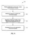
- a method for extracting a medical device from a medical device packageincludes providing a medical device package, with a medical device contained therein, and a connector.
- the provided medical device packageincludes a body with at least one chamber defined therein.
- the medical device packagealso includes at least one deformable projection within the chamber(s), with the deformable projection(s) being configured to deform resiliently upon contact with a medical device during insertion of the medical device at least partially within the chamber and, thereby, removably retain the medical device at least partially within the chamber.
- the methodalso includes the steps of inserting at least a portion of the connector into the chamber, engaging the medical device with the connector, and extracting the engaged medical device from the chamber of the medical device package with the connector.
- the connectorcan be employed to resiliently deform the deformable projection(s) either during engagement between the medical device and connector or subsequent to such engagement and prior to extraction of the engaged medical device.
- FIG. 1is a simplified cross-sectional side view of a medical device package according to an exemplary embodiment of the present invention
- FIG. 2is a simplified cross-sectional side view of the medical device package of FIG. 1 containing a medical device;
- FIG. 3is a simplified exploded perspective view of the body, proximal end cap member and distal end cap member of the medical device of FIG. 1 ;
- FIG. 4is a simplified exploded perspective view of portions of the body and proximal cap member of the medical device package of FIG. 1 , with dashed lines indicating features that are not visible in the perspective view of FIG. 4 ;
- FIG. 5is a simplified perspective view of a medical device that can be contained within exemplary embodiments of medical device packages according to the present invention
- FIG. 6Ais a simplified cross-sectional top view (as viewed along line A-A′ in FIG. 1 .) of the medical device package of FIG. 1 ;
- FIGS. 6B through 6Eare simplified cross-sectional top views of medical device packages according to various exemplary embodiments of the present invention, with each of FIGS. 6B through 6E depicting alternative deformable projection configurations;
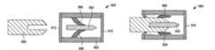
- FIG. 7Ais a simplified cross-sectional side view of a medical device package according to another embodiment of the present invention.
- FIG. 7Bis a simplified cross-sectional side view of the medical device package of FIG. 7A containing a medical device;
- FIG. 8Ais a simplified cross-sectional side view of a medical device package according to yet another embodiment of the present invention.
- FIG. 8Bis a simplified cross-sectional side view of the medical device package of FIG. 8A containing a medical device;
- FIG. 9Ais a simplified cross-sectional side view of a medical device package according to still another embodiment of the present invention.
- FIG. 9Bis a simplified cross-sectional side view of the medical device package of FIG. 9A containing a medical device
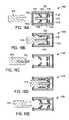
- FIGS. 10A through 10Care simplified cross-sectional side views of a medical device package depicting various deformable projection configurations
- FIG. 11is a flow chart illustrating a sequence of steps in a process for extracting a medical device from a medical device package according to an embodiment of the present invention
- FIGS. 12A through 12Care schematic, cross-sectional side views depicting various stages of the process of FIG. 11 ;
- FIG. 13is a flow chart illustrating a sequence of steps in a process for extracting a medical device from a medical device package that includes a frangible deformable projection according to another embodiment of the present invention
- FIGS. 14A through 14Care schematic, cross-sectional views depicting various stages of the process of FIG. 13 ;
- FIG. 15is a flow chart illustrating a sequence of steps in a process for extracting a medical device from a medical device package and subsequently disabling the medical device according to an embodiment of the present invention
- FIGS. 16A through 16Eare schematic, cross-sectional side views depicting various stages of the process of FIG. 15 ;
- FIG. 17is a simplified perspective view of a medical device package that includes a plurality of chambers according to a further embodiment of the present invention.
- FIGS. 18A and 18Bare simplified cross-sectional top views (along line B-B′ of FIG. 17 ) of a portion of the medical device package of FIG. 17 without ( FIG. 18A ) and with ( FIG. 18B ) medical devices retained therein; and
- FIG. 19is a simplified perspective view of an exemplary embodiment of a medical device package according to the present invention.
- FIGS. 1-4are simplified depictions of a medical device package 100 according to an exemplary embodiment of the present invention.
- FIG. 5is a simplified depiction of a medical device 500 that can be contained within medical device package 100 .
- FIG. 6Ais a simplified top cross-sectional view of medical device package 100 .
- medical device package 100is configured to securely, yet removably, contain a medical device (such as medical device 500 ), as depicted in FIG. 2 .
- medical device package 100includes a body 102 with a chamber 104 defined therein. Body 102 has a proximal end 106 and a distal end 108 .
- medical device package 100includes first and second deformable projections 110 and 112 , respectively, that are disposed within chamber 104 .
- medical device package 100also includes a proximal cap member 114 and a distal cap member 116 .
- first and second deformable projections 110 and 112are configured to deform resiliently upon contact with medical device 500 during insertion of medical device 500 into chamber 104 and, thereby, removably retain medical device 500 within chamber 104 .
- FIG. 2depicts medical device 500 as being completely inserted in chamber 104
- medical device packages according to embodiments of the present inventioncould be configured such that a medical device is only partially inserted with a chamber and removably retained partially within the chamber.
- body 102includes a rim 118 defining a proximal end aperture 120 (as shown in FIGS. 3 and 4 ), opposing first and second inner walls 122 and 124 , and opposing third and fourth inner walls 126 and 128 .
- First, second, third and fourth inner walls 122 , 124 , 126 , and 128define chamber 104 .
- First deformable projection 110is attached to first inner wall 122 of body 102 .
- Second deformable projection 112is attached to second inner wall 124 of body 102 .
- first and second deformable projections 110 and 112each form an angle ⁇ with first and second inner walls 122 and 124 , respectively.
- Angle ⁇can be any suitable angle, but angle ⁇ is typically less than 90 degrees, for example, in the range of from 20 degrees to 80 degrees. Lesser ⁇ angles may result in deformable projections that retain medical devices with a relatively weaker retaining force in comparison to deformable projections with greater a angles. However, deformable projections with lesser ⁇ angles may be more robust in terms of being able to retain medical devices with a wider range of sizes than deformable projections with greater ⁇ angles.
- Medical device package 100is configured to receive, and to securely and removably retain, a medical device (e.g., medical device 500 of FIG. 5 ), at least partially therein, as illustrated in FIG. 2 for a circumstance that the medical device is completely within the medical device package.
- medical device 500is shown securely and removably retained between deformable projections 110 and 112 in chamber 104 .
- Deformable projections 110 and 112have been resiliently deformed, and angle ⁇ decreased, by the presence of medical device 500 in medical device package 100 .
- Angle ⁇enables first and second deformable projections 110 and 112 to beneficially act as guides when medical device 500 is inserted into chamber 104 .
- First and second deformable projections 110 and 112can, therefore, minimize the risk of damage to medical device 500 as it is loaded (i.e., inserted) into chamber 104 .
- FIG. 5is a perspective view of medical device 500 that can, as previously noted, be securely and removably contained within medical device package 100 .
- Medical device 500includes a test strip 504 and a dermal tissue penetration member 502 and, therefore, can be considered an integrated medical device.
- Test strip 504has a reaction area (not shown) and electrical contacts 506 that terminate on a distal end 510 of medical device 500 .
- Electrical contacts 506are made of any suitable conductive material, such as carbon.
- Dermal tissue penetration member 502includes a lancet 520 adapted to pierce a user's skin and draw blood into the reaction area of test strip 504 .
- Further descriptions of integrated medical devices that can be contained within embodiments of medical device packages according to the present inventionare in International Application No. PCT/GB01/05634 (published as WO 02/49507 on Jun. 27, 2002) and U.S. patent application Ser. No. 10/143,399, both of which are fully incorporated herein by reference.
- dermal tissue penetration member 502can be fabricated, for example, by a progressive die-stamping technique, as disclosed in the aforementioned International Application No. PCT/GB01/05634 (published as WO 02/49507 on Jun. 27, 2002) and U.S. patent application Ser. No. 10/143,399.
- rim 118includes sufficient surface area to enable proximal cap member 114 to be adhered to rim 118 by processes known to those skilled in the art, including, but not limited to, heat sealing processes. In this manner, proximal cap member 114 , along with distal cap member 116 and body 102 of medical device package 100 , provides a sterility barrier and ambient humidity protection for a medical device contained within the chamber of the medical device package.
- Body 102can be formed of any suitable material known to those of skill in the art including, for example, rigid plastic materials such as high density polyethylene (HDPE), polystyrene, polycarbonate and polyester. Such rigid plastic materials are impervious to puncturing and to air and/or air-borne bacteria and, therefore, provide a sterility barrier and a puncture-resistant protective barrier. It can be particularly beneficial in terms of humidity protection for body 102 to be formed of, or include, a layer of a desiccant-loaded high-density polyethylene (e.g., 2AP desiccant-loaded high-density polyethylene, commercially available from Airsec of France). Furthermore, carbon black can combined with a rigid material (e.g., a combination of carbon black and HDPE) to provide enhanced light protection capabilities to the body.
- rigid plastic materialssuch as high density polyethylene (HDPE), polystyrene, polycarbonate and polyester.
- HDPEhigh density polyethylene
- polystyrenepolystyrene
- Proximal cap member 114is configured to cover proximal end aperture 120 once a medical device has been received in chamber 104 .
- Proximal cap member 114(as well as distal cap member 116 ) can be, for example, a breachable film such as breachable metallic foil.
- Other suitable materials for proximal cap member 114 and/or distal cap member 116include paper, polymer and Tyvek. Those skilled in the art will also recognize that proximal cap member 114 and/or distal cap member 116 can alternatively be rigid and/or re-closable.
- First and second deformable projections 110 and 112can be formed of resiliently and/or permanently deformable materials including, for example, polystyrene, polycarbonate, and polyester or elastomeric materials including silicone, Teflon, latex or other types of rubber.
- the use of a deformable material for the deformable projectionsis beneficial in that damage to a medical device during insertion, containment and removal is minimized.
- the deformable projectionscan be optionally coated with a material that reduces the likelihood of damage to a medical device and improves the frictional grip between first and second deformable projections 110 and 112 and a medical device.
- first and second deformable projections 110 and 112each include a projection surface 110 a and 112 a , respectively.
- Projection surfaces 110 a and 112 acan, for example, be smoothly curved with no sharp edges to reduce the likelihood of damage to a medical device.
- each of projection surfaces 110 a and 112 acan be optionally configured to contact a medical device (e.g., medical device 500 ) at more than one location so that the medical device is restricted from potentially damaging rotation, pivoting or sliding during storage or transit.
- Projection surfaces 110 a and 112 aalso serve to guide a medical device away from first and second inner walls 122 and 124 during loading of the medical device into package 100 , thereby preventing damage to the medical device due to collision with the first and second inner walls 122 and 124 .
- FIG. 2is a cross-sectional view of medical device package 100 with medical device 500 retained therein prior to use of medical device 500 (i.e., prior to extraction of medical device 500 from the medical device package 100 for use).
- medical device 500is disposed between first and second deformable projections 110 and 112 and is positioned substantially parallel to first and second walls 122 and 124 .
- Medical device 500is securely retained within cavity 104 via a frictional interaction with first and second deformable projections 110 and 112 (e.g., a combination of the coefficient of friction between the deformable projections and a retained medical device and a retaining force [e.g., a “squeezing” force] provided by the resilient nature of the deformable projections).
- Lancet 520is retained within chamber 104 and, thus, protected from inadvertent damage.
- FIGS. 6B through 6Edepict alternative exemplary configurations of deformable projections within a medical device package according to the present invention.
- FIG. 6Bdepicts a configuration 200 wherein a medical device package body 202 has a chamber 204 therein and the medical device package body 202 includes four deformable projections 206 , 208 , 210 and 212 .
- FIG. 6Cdepicts a configuration 220 wherein a body 222 of a medical device package has a chamber 224 therein and the body 222 includes five staggered deformable projections 226 , 228 , 230 , 232 and 234 .
- the deformable projections of FIG. 6Care staggered in that deformable projections 226 and 228 are not in an opposing relationship with any of deformable projections 230 , 232 and 234 .
- FIG. 6Ddepicts a configuration 240 wherein a medical device package body 242 has a chamber 244 therein and the medical device package body 242 includes six deformable projections 246 , 248 , 250 , 252 , 254 and 256 .
- FIG. 6Edepicts a configuration 260 wherein a medical device package body 262 has a chamber 264 therein and medical device package body 262 includes three staggered deformable projections 266 , 268 and 270 .
- the deformable projectionshave been configured to securely and removably retain a medical device without any significant or deleterious deformation of the medical device.
- the deformable projectionsserve to prevent significant movement of a medical device within the medical device package, thus avoiding mechanical damage to the medical device.
- medical device package 300includes a body 302 , with a chamber 304 defined therein, and a distal cap member 306 .
- Medical device package 300includes first and second deformable projections 310 and 312 , respectively, that are disposed within chamber 304 .
- First and second deformable projections 310 and 312have a curved shape (with no sharp edges) that aids in preventing damage to a medical device during insertion, storage and removal from medical device package 300 .
- first and second deformable projections 310 and 312flex to securely and removably retain medical device 500 (see FIG. 7B ).
- the use of curved deformable projectionsfacilitates insertion and extraction of a medical device by providing for the medical device to easily slide over these deformable projections.
- medical device package 320includes a body 322 , with a chamber 324 defined therein, and a distal cap member 326 .
- Medical device package 320also includes first and second deformable projections 330 and 332 , respectively, disposed within chamber 324 .
- first and second deformable projections 330 and 332move longitudinally toward distal cap member 326 such that the distance L 1 of FIG. 8A is increased to distance L 2 of FIG. 8B .
- L 1can range, for example, from half to two-thirds the length of body 322 .
- L 2can be, for example, 25% to 50% greater than L 1 and in the range of from two-thirds to three-fourths the length of body 322 .
- each of first and second deformable projections 330 and 332contact body 322 at two points in order to enhance the physical stability of medical device retained within medical device package 320 .
- medical device package 340includes a body 342 , with a chamber 344 defined therein, and a distal cap member 346 .
- Medical device package 340also includes first and second deformable projections 350 and 352 , respectively, disposed within chamber 344 . As depicted in FIGS. 9A and 9B , each of first and second deformable projections 350 and 352 is configured and attached to body 342 to form a looped (e.g., roughly U-shaped) configuration.
- first and second deformable projections 350 and 352flatten such that relatively large areas of contact are made with medical device 500 , facilitating the secure retention of the medical device within medical device package 340 .
- the first and second deformable projectionscould be configured such that each provides multiple points of contact with the medical device.
- FIGS. 10A through 10Cshow various configurations of deformable projections within a medical device package according to the present invention.
- a medical devicei.e., medical device 500 of FIG. 5
- FIGS. 10A through 10Cshow various configurations of deformable projections within a medical device package according to the present invention.
- a medical devicei.e., medical device 500 of FIG. 5
- FIGS. 10A through 10Cshow various configurations of deformable projections within a medical device package according to the present invention.
- a medical devicei.e., medical device 500 of FIG. 5
- FIG. 10Adepicts a configuration 400 wherein a medical device package body 402 , with a chamber 404 therein, includes an elevation 406 and a deformable projection 408 .
- the combination of deformable projection 408 and elevation 406provides a relatively large area of contact between medical device 500 and elevation 406 , thereby restricting movement of, and alleviating risk of damage to, medical device 500 .
- Elevation 406can be formed, for example, of either a rigid or a deformable material. In the circumstance that elevation 406 is formed of a rigid material, the position of a medical device within configuration 400 is accurately controlled since the medical device is retained against the rigid elevation by deformable projection 408 .
- FIG. 10Bdepicts a configuration 420 wherein a medical device package body 422 , with a chamber 424 therein, includes a single deformable projection 426 .
- a medical devicei.e., medical device 500
- the flat surface contact of the medical device package body 422helps ensure that medical device 500 is securely and removably retained.
- FIG. 10Cdepicts a configuration 440 wherein a medical device package body 442 , with a chamber 444 therein, includes four deformable projections 446 , 448 , 450 and 452 .
- the use of multiple deformable projectionsbeneficially provides multiple contact surfaces to hold a medical device securely and to prevent damage to the medical device.
- FIG. 12CFurther aspects of various embodiments of medical device packages according to the present invention are described hereafter in relation to various processes for removing (i.e., extracting) a medical device from a medical device package.
- removal of medical device 500can be accomplished using a connector 600 (see, for example, FIG. 12C described further below).
- Connector 600is shaped and sized, and otherwise configured and adapted, to extract (i.e., remove) a medical device (e.g., medical device 500 of FIG. 5 ) from medical device packages according to exemplary embodiments of the present invention.
- connector 600can advantageously be used to mechanically and/or manually manipulate such a medical device once the medical device has been extracted from the medical device package.
- connector 600can be used to transfer a medical device from a medical device package to a metering system.
- connector 600may be a component (either a removable component or a permanently integrated component) of a metering system (e.g., an analytical meter configured to determine analyte concentrations in biological fluid samples).
- a metering systeme.g., an analytical meter configured to determine analyte concentrations in biological fluid samples.
- connector 600can be combined with medical device packages to form a kit as described in co-pending U.S. patent application Ser. No. 10/666,154, which is hereby incorporated in full by reference.
- FIGS. 11 and 12 A- 12 Cdepict a process 700 for removing a medical device (i.e., medical device 500 of FIG. 5 ) from medical device package 100 of FIGS. 1-4 .
- Process 700includes first providing a medical device contained within medical device package 100 and a connector 600 , as set forth in step 710 of FIG. 11 and depicted in FIG. 12A .
- connector 600is inserted into chamber 104 of medical device package 100 (see step 720 of FIG. 11 ) by breaching proximal cap member 114 .
- Connector 600is then engaged with medical device 500 .
- connector 600causes first and second deformable projections 110 and 112 to deform (see step 730 of FIG. 11 and the depiction of FIG. 12B ).
- Connector 600 and engaged medical device 500are then extracted from chamber 104 of medical device package 100 , as set forth in step 740 of FIG. 11 and shown in FIG. 12C .
- FIG. 12Cillustrates a circumstance where connector 600 and medical device 500 are extracted through proximal cap member 114 (which had been previously breached in step 720 ).
- connector 600could be used to extract engaged medical device 500 by pushing medical device 500 through distal cap member 116 (if distal cap member 116 is formed of a breachable material such as a metallic foil).
- the distal cap membercan be removed prior to extraction of the medical device in order to avoid potential damage to the medical device during breaching of the distal cap member.
- the force required for connector 600 to engage with the medical device in step 730is, for example, approximately 2N.
- the deformable projectionsreversibly bend (i.e., deform) away from the medical device toward the body of the medical device package.
- Each of the steps of process 700can be performed, for example, either manually by a user and/or with the aid of a mechanical and/or electrical device.
- FIGS. 13 and 14 A- 14 Cdepict a process 800 for removing a medical device (i.e., medical device 500 of FIG. 5 ) from a medical device package 900 according to an exemplary embodiment of the present invention.
- Process 800includes first providing a medical device contained within medical device package 900 and a connector 600 , as set forth in step 810 of FIG. 13 and depicted in FIG. 14A .
- Medical device package 900includes a body 902 with a chamber 904 defined therein. Medical device package 900 also includes first and second frangible deformable projections 906 and 908 , respectively, a distal cap member 910 and a proximal cap member 912 . First and second frangible deformable projections 906 and 908 are configured to deform resiliently upon contact with a medical device during insertion of the medical device at least partially within the chamber. Thereafter, first and second frangible deformable projections 906 and 908 removably retain the medical device within chamber 904 . Furthermore, first and second frangible deformable projections 906 and 908 are also adapted to break upon a predetermined deformation (as described below with respect to step 830 and FIGS. 14B and 14C ).
- connector 600is inserted into chamber 904 of medical device package 900 (see step 820 of FIG. 13 ) by breaching proximal cap member 912 .
- Connector 600is then engaged with medical device 500 .
- connector 600deforms first and second frangible deformable projections 906 and 908 to a predetermined point at which first and second frangible deformable projections 906 and 908 break free (either partially or fully) of body 902 , as set forth in step 830 of FIG. 13 and depicted in FIG. 14B .
- Connector 600 and engaged medical device 500are then extracted from chamber 904 of medical device package 900 , as set forth in step 840 of FIG. 13 and shown in FIG. 14C .
- FIG. 15is a flow chart illustrating a sequence of steps in a process 1000 for extracting a medical device from a medical device package 1100 for use and subsequently disabling the medical device after use according to an exemplary embodiment of the present invention.
- process 1000includes first providing a medical device 510 contained within medical device package 1100 and a connector 610 , as set forth in step 1010 of FIG. 15 and depicted in FIG. 16A .
- Medical device package 1100includes a body 1102 with a chamber 1104 defined therein. Medical device package 1100 also includes first and second deformable projections 1106 and 1108 , respectively, a distal cap member 1110 and a proximal cap member 1112 . First and second deformable projections 1106 and 1108 are configured to deform resiliently upon contact with a medical device during insertion of the medical device at least partially within the chamber. Thereafter, first and second deformable projections 1106 and 1108 removably retain the medical device within chamber 1104 .
- Medical device package 1100also includes first and second frangible projections 1114 and 1116 (disposed within chamber 1104 ), respectively, and first and second rigid projections 1118 and 1120 (also disposed within chamber 1104 ), respectively.
- First and second frangible projections 1114 and 1116are adapted to break upon a predetermined deformation (as described below with respect to FIG. 16D and step 1050 of FIG. 15 ).
- first and second frangible projections 1114 and 1116are also adapted to (i) serve as a stop mechanism during the initial insertion of an unused medical device into medical device package 1100 such that the unused medical device does not become engaged with first and second rigid projections 1118 and 1120 and (ii) serve as a stop mechanism during engagement between a connector and a medical device.
- first and second rigid projections 1118 and 1120are intended to engage (e.g., snap fit) into recesses 520 on medical device 510 upon re-insertion of a medical device 510 into package 1100 after use.
- proximal cap member 1112is breached (e.g., ruptured) with connector 610 , or alternatively is manually opened or removed, and at least a portion of the connector inserted into chamber 1104 .
- the medical device 510is then engaged by the connector 610 , as set forth in step 1030 of FIG. 15 and depicted in FIG. 16B .
- the first and second deformable projections 1106 and 1108reversibly bend away from the medical device 510 and toward body 1102 .
- step 1040 of FIG. 15the connector and engaged medical device are extracted from chamber 1104 for use and the first and second deformable projections 1106 and 1108 bend back away from the body, as illustrated in FIG. 16C .
- step 1050the connector and engaged medical device are inserted back into chamber 1104 such that first and second frangible projections 1114 and 1116 are broken and first and second rigid projections 1118 and 1120 engage with medical device 510 such that medical device 510 is prevented from being re-extracted from chamber 1104 , thereby disabling the medical device from reuse (see FIG. 16D ).
- the connector 610is then disengaged from the medical device 510 and withdrawn from medical device package 1100 , as set forth in step 1060 and as shown in FIG. 16E .
- the medical device 510is disabled by virtue of the medical device breaking first and second frangible projections 1114 and 1116 and subsequently being engaged (e.g., snap-fit or lodged) into first and second rigid projections 1118 and 1120 such that the force required to remove the medical device 510 from the chamber is greater than the force required to disengage theconnector 610 from the medical device 510 . Therefore, an attempt to re-extract the medical device with the connector would be unsuccessful since the connector would become disengaged from the medical device before sufficient force could be applied to extract the lodged medical device.
- the force required to insert the medical device into the medical device package and disable the medical deviceis, for example, approximately 7N.
- disablement of the medical deviceis a result of the medical device being engaged (e.g., snap fit) with the first and second rigid projections such that it cannot be re-extracted using the connector.
- Processes according to embodiments of the present inventioncan be performed manually and/or automatically. Furthermore, such processes can be, for example, performed by an integrated device that combines an analytical meter and a connector in a configuration that provides for (i) a medical device to be extracted from a medical device package; (ii) a sample (e.g., a whole blood sample) to be obtained from a user and (iii) an analytical result (e.g., blood glucose concentration of the whole blood sample) to be determined, all by a single operation of the integrated device.
- Mechanical motionsmay be incorporated into a lancet cocking action, new test strip deployment and/or ejection.
- FIGS. 17 , 18 A and 18 Bdepict a medical device package 1200 according to an exemplary embodiment of the present invention with FIG. 18B illustrating a medical device (i.e., medical device 500 of FIG. 5 ) contained within the medical device package 1200 .
- Medical device package 1200includes a body 1202 with a plurality of chambers 1204 defined therein. Although, for the purpose of explanation only, twelve chambers are depicted in the embodiment of FIG. 17 , medical device package can have any suitable number of chambers.
- Each of the plurality of chambershas a first and second deformable projection 1206 and 1208 , respectively, disposed therein, as shown in FIGS. 18A and 18B .
- Chambers 1204 of medical device package 1200are configured in a regular array consisting of two rows (labeled L in FIG. 17 ) of six chambers each.
- medical device package 1200is depicted, for the purpose of explanation only, as including chambers configured in two rows, medical device packages according to embodiments of the present invention can include chambers configured in any suitable arrangement including, for example, a single row, a plurality of rows or any other suitable geometric configuration.
- medical device package 1200includes a plurality of chambers (e.g., 12 chambers), medical device package 1200 can contain an equal plurality of medical devices with one medical device being contained in each chamber.
- the regular array configuration of the chambers of medical device package 1200facilitates integration into an analytical measurement system kit that includes (i) a compact measuring system, (ii) a medical device package (e.g., medical device package 1200 , and (iii) medical devices.
- deformable projections in medical device package 1200enables reliable removal of medical devices contained in chambers 1204 without deleterious canting of the medical device as it is dispensed from chamber.
- distance D 1represents the distance between first and second deformable projections 1206 and 1208 when a medical device has not been inserted into chamber 1204 .
- D 1can be any suitable distance, for example a distance in the range from about 0.1 millimeters to 5 millimeters and typically from about 0.25 to 0.5 millimeters. In general, distance D 1 is sufficient to accommodate a medical device without damaging the medical device but sufficiently small to provide a secure fit when holding a medical device.
- the distance (or gap) between deformable projectionse.g., distance D 1 in FIG. 18A and gap G in FIG.
- the deformable projections 1can also be zero or be a “negative” distance (i.e., the deformable projections can overlap one another) for medical device packages wherein the deformable projections are in a staggered configuration (e.g., the deformable projection configuration of FIG. 6E ).
- Distance D 2(see FIG. 18B ) represents the distance between first and second deformable projections 1206 and 1208 when a medical device has been inserted into chamber 1204 .
- Distance D 2is the thickness of medical device 500 .
- Typical, but non-limiting, D 2 distancesare in the range from about 0.1 millimeters to 5 millimeters.
- Medical device package 1200can be formed, for example, as a unitary whole from molded plastic or can be assembled from multiple single-chamber medical device packages.
- FIG. 19illustrates a medical device package 2200 with a body 2202 and a plurality of chambers 2204 defined in body 2202 .
- Chambers 2204are arranged in a stacked regular radial array that is symmetrical about a plane that perpendicularly bisects longitudinal axis C-C′ of medical device package 2200 .
- Such symmetryis advantageous in affording leeway for the orientation of medical device package 2200 during insertion into an analysis instrument.
- Medical device package 2200also includes a plurality of deformable projections 2206 disposed within each of the plurality of chambers 2204 .
- medical device package 2200is depicted, for the purpose of explanation only, as including a plurality of deformable projections 2206 on top and bottom inner surface of the chambers 2204 , medical device packages according to embodiments of the present invention can include a plurality of deformable projections 2206 in any suitable arrangement and locations within chambers 2204 .
- medical device package 2200has a central cylindrically-shaped aperture 2208 .
- Aperture 2208extends through medical device package 2200 and is configured such that an analysis instrument (not shown) can employ aperture 2208 to mechanically secure medical device package 2200 during use.
- Medical device package 2200is beneficially constructed of molded plastic or other material that is impervious to air and/or air-borne bacteria, to provide a sterile-protective and puncture-resistant barrier.
- Suitable materialsinclude, but are not limited to, polystyrene, polyethylene, polycarbonate and polyester.
- the deformable projection(s)securely retain(s) a medical device within the medical device package's chamber with insignificant deformation of the medical device. It is also noted that the orientation of a medical device within embodiments of medical device packages according to the present invention can vary from the orientation depicted in the figures.
- embodiments of medical device packages according to the present inventioncan be secondarily packaged for single use in, for example, a vial configured for dispensing the medical device packages.
- the secondary packagemay be constructed of material containing desiccant or may contain separately packaged desiccant for maintaining contents moisture free.
- Such medical devicesinclude, but are not limited to, integrated medical devices that include a combination of a test strip and a lancet, examples of which are described in the aforementioned International Application No. PCT/GB01/05634 (published as WO 02/49507 on Jun. 27, 2002) and U.S. patent application Ser. No. 10/143,399, both of which are fully incorporated herein by reference.
- test stripsmay have, but are not limited to, an electrochemical or photometric configuration. For illustrative purposes only, medical devices in various figures of the present disclosure were depicted as having an electrochemical configuration.
- medical device packages according to embodiments of the present inventioncan be employed with medical device adapted for the measurement of, for example, glucose, ketones, glycated albumin, coagulation parameters and cholesterol of a sample.
- medical device packages according to the present inventionmay be contained within a combined sample collection and metering system designed for in-situ testing. Examples of such systems designed for in-situ testing are disclosed in International Patent Application No. PCT/US01/07169 (published as WO 01/64105 A1 on Sep. 7, 2001) and International Patent Application No. PCT/GB02/03772 (published as WO 03/015627 A1 on Feb. 27, 2003), each of which is fully incorporated herein by reference.
Landscapes
- Health & Medical Sciences (AREA)
- Life Sciences & Earth Sciences (AREA)
- Surgery (AREA)
- General Physics & Mathematics (AREA)
- Physics & Mathematics (AREA)
- Heart & Thoracic Surgery (AREA)
- Engineering & Computer Science (AREA)
- Biomedical Technology (AREA)
- Nuclear Medicine, Radiotherapy & Molecular Imaging (AREA)
- Medical Informatics (AREA)
- Molecular Biology (AREA)
- Animal Behavior & Ethology (AREA)
- General Health & Medical Sciences (AREA)
- Public Health (AREA)
- Veterinary Medicine (AREA)
- Packages (AREA)
- Infusion, Injection, And Reservoir Apparatuses (AREA)
- Measurement Of The Respiration, Hearing Ability, Form, And Blood Characteristics Of Living Organisms (AREA)
Abstract
Description
Claims (4)
Priority Applications (12)
| Application Number | Priority Date | Filing Date | Title |
|---|---|---|---|
| US10/816,002US7516845B2 (en) | 2004-03-31 | 2004-03-31 | Medical device package with deformable projections |
| CA002502127ACA2502127A1 (en) | 2004-03-31 | 2005-03-22 | Medical device package with deformable projections |
| AU2005201232AAU2005201232A1 (en) | 2004-03-31 | 2005-03-22 | Medical device package with deformable projections |
| TW094109912ATW200538361A (en) | 2004-03-31 | 2005-03-30 | Medical device package with deformable projections |
| NO20051598ANO20051598L (en) | 2004-03-31 | 2005-03-30 | Medical device gasket with deformable projections. |
| SG200501992ASG115820A1 (en) | 2004-03-31 | 2005-03-30 | Medical device package with deformable projections |
| KR1020050026386AKR20060044991A (en) | 2004-03-31 | 2005-03-30 | Medical device package with deformable protrusions |
| RU2005109225/14ARU2005109225A (en) | 2004-03-31 | 2005-03-30 | PACKING OF MEDICAL DEVICE WITH DEFORMABLE ACCESSORIES |
| JP2005099362AJP2005288171A (en) | 2004-03-31 | 2005-03-30 | Medical device package with deformable protrusion |
| MXPA05003370AMXPA05003370A (en) | 2004-03-31 | 2005-03-30 | Medical device package with deformable projections. |
| CNA200510062971XACN1683218A (en) | 2004-03-31 | 2005-03-31 | Medical device packaging with deformable protrusions |
| EP05252014AEP1582169A3 (en) | 2004-03-31 | 2005-03-31 | Medical device package with deformable retaining projections |
Applications Claiming Priority (1)
| Application Number | Priority Date | Filing Date | Title |
|---|---|---|---|
| US10/816,002US7516845B2 (en) | 2004-03-31 | 2004-03-31 | Medical device package with deformable projections |
Publications (2)
| Publication Number | Publication Date |
|---|---|
| US20050218024A1 US20050218024A1 (en) | 2005-10-06 |
| US7516845B2true US7516845B2 (en) | 2009-04-14 |
Family
ID=34887753
Family Applications (1)
| Application Number | Title | Priority Date | Filing Date |
|---|---|---|---|
| US10/816,002Active2026-10-16US7516845B2 (en) | 2004-03-31 | 2004-03-31 | Medical device package with deformable projections |
Country Status (12)
| Country | Link |
|---|---|
| US (1) | US7516845B2 (en) |
| EP (1) | EP1582169A3 (en) |
| JP (1) | JP2005288171A (en) |
| KR (1) | KR20060044991A (en) |
| CN (1) | CN1683218A (en) |
| AU (1) | AU2005201232A1 (en) |
| CA (1) | CA2502127A1 (en) |
| MX (1) | MXPA05003370A (en) |
| NO (1) | NO20051598L (en) |
| RU (1) | RU2005109225A (en) |
| SG (1) | SG115820A1 (en) |
| TW (1) | TW200538361A (en) |
Cited By (10)
| Publication number | Priority date | Publication date | Assignee | Title |
|---|---|---|---|---|
| US20110288596A1 (en)* | 2009-02-26 | 2011-11-24 | Medartis Ag | Support and Mounting for Surgical Objects |
| US8486717B2 (en) | 2011-01-18 | 2013-07-16 | Symbolics, Llc | Lateral flow assays using two dimensional features |
| US20160213908A1 (en)* | 2013-09-30 | 2016-07-28 | Georgia Tech Research Corporation | Microneedle Patches, Systems, and Methods |
| US9599615B2 (en) | 2013-03-13 | 2017-03-21 | Symbolics, Llc | Lateral flow assays using two dimensional test and control signal readout patterns |
| US9874556B2 (en) | 2012-07-18 | 2018-01-23 | Symbolics, Llc | Lateral flow assays using two dimensional features |
| US20180356390A1 (en)* | 2015-12-08 | 2018-12-13 | Roche Diabetes Care, Inc. | Test Element Retention Dividers |
| US10828478B2 (en) | 2014-04-24 | 2020-11-10 | Georgia Tech Research Corporation | Microneedles and methods of manufacture thereof |
| US11395711B2 (en) | 2019-06-05 | 2022-07-26 | Stryker European Operations Limited | Packaging systems and methods for mounting a tool on a surgical device using the same |
| US11690680B2 (en) | 2019-03-19 | 2023-07-04 | Mako Surgical Corp. | Trackable protective packaging for tools and methods for calibrating tool installation using the same |
| US12161489B2 (en) | 2017-04-12 | 2024-12-10 | Mako Surgical Corp. | Packaging systems and methods for mounting a tool on a surgical device |
Families Citing this family (79)
| Publication number | Priority date | Publication date | Assignee | Title |
|---|---|---|---|---|
| US6036924A (en) | 1997-12-04 | 2000-03-14 | Hewlett-Packard Company | Cassette of lancet cartridges for sampling blood |
| US6391005B1 (en) | 1998-03-30 | 2002-05-21 | Agilent Technologies, Inc. | Apparatus and method for penetration with shaft having a sensor for sensing penetration depth |
| DE10057832C1 (en) | 2000-11-21 | 2002-02-21 | Hartmann Paul Ag | Blood analysis device has syringe mounted in casing, annular mounting carrying needles mounted behind test strip and being swiveled so that needle can be pushed through strip and aperture in casing to take blood sample |
| US8641644B2 (en) | 2000-11-21 | 2014-02-04 | Sanofi-Aventis Deutschland Gmbh | Blood testing apparatus having a rotatable cartridge with multiple lancing elements and testing means |
| US7041068B2 (en) | 2001-06-12 | 2006-05-09 | Pelikan Technologies, Inc. | Sampling module device and method |
| US7344507B2 (en) | 2002-04-19 | 2008-03-18 | Pelikan Technologies, Inc. | Method and apparatus for lancet actuation |
| JP4272051B2 (en) | 2001-06-12 | 2009-06-03 | ペリカン テクノロジーズ インコーポレイテッド | Blood sampling apparatus and method |
| US9226699B2 (en) | 2002-04-19 | 2016-01-05 | Sanofi-Aventis Deutschland Gmbh | Body fluid sampling module with a continuous compression tissue interface surface |
| EP1395185B1 (en) | 2001-06-12 | 2010-10-27 | Pelikan Technologies Inc. | Electric lancet actuator |
| JP4209767B2 (en) | 2001-06-12 | 2009-01-14 | ペリカン テクノロジーズ インコーポレイテッド | Self-optimized cutting instrument with adaptive means for temporary changes in skin properties |
| US7981056B2 (en) | 2002-04-19 | 2011-07-19 | Pelikan Technologies, Inc. | Methods and apparatus for lancet actuation |
| WO2002101359A2 (en) | 2001-06-12 | 2002-12-19 | Pelikan Technologies, Inc. | Integrated blood sampling analysis system with multi-use sampling module |
| US9795747B2 (en) | 2010-06-02 | 2017-10-24 | Sanofi-Aventis Deutschland Gmbh | Methods and apparatus for lancet actuation |
| AU2002344825A1 (en) | 2001-06-12 | 2002-12-23 | Pelikan Technologies, Inc. | Method and apparatus for improving success rate of blood yield from a fingerstick |
| US8337419B2 (en) | 2002-04-19 | 2012-12-25 | Sanofi-Aventis Deutschland Gmbh | Tissue penetration device |
| US7749174B2 (en) | 2001-06-12 | 2010-07-06 | Pelikan Technologies, Inc. | Method and apparatus for lancet launching device intergrated onto a blood-sampling cartridge |
| US9427532B2 (en) | 2001-06-12 | 2016-08-30 | Sanofi-Aventis Deutschland Gmbh | Tissue penetration device |
| US7344894B2 (en) | 2001-10-16 | 2008-03-18 | Agilent Technologies, Inc. | Thermal regulation of fluidic samples within a diagnostic cartridge |
| JP4256786B2 (en)* | 2002-02-12 | 2009-04-22 | アークレイ株式会社 | measuring device |
| US7524293B2 (en) | 2002-04-19 | 2009-04-28 | Pelikan Technologies, Inc. | Method and apparatus for penetrating tissue |
| US7229458B2 (en) | 2002-04-19 | 2007-06-12 | Pelikan Technologies, Inc. | Method and apparatus for penetrating tissue |
| US7491178B2 (en) | 2002-04-19 | 2009-02-17 | Pelikan Technologies, Inc. | Method and apparatus for penetrating tissue |
| US7141058B2 (en) | 2002-04-19 | 2006-11-28 | Pelikan Technologies, Inc. | Method and apparatus for a body fluid sampling device using illumination |
| US8267870B2 (en) | 2002-04-19 | 2012-09-18 | Sanofi-Aventis Deutschland Gmbh | Method and apparatus for body fluid sampling with hybrid actuation |
| US7582099B2 (en) | 2002-04-19 | 2009-09-01 | Pelikan Technologies, Inc | Method and apparatus for penetrating tissue |
| US9795334B2 (en) | 2002-04-19 | 2017-10-24 | Sanofi-Aventis Deutschland Gmbh | Method and apparatus for penetrating tissue |
| US7232451B2 (en) | 2002-04-19 | 2007-06-19 | Pelikan Technologies, Inc. | Method and apparatus for penetrating tissue |
| US7331931B2 (en) | 2002-04-19 | 2008-02-19 | Pelikan Technologies, Inc. | Method and apparatus for penetrating tissue |
| US7976476B2 (en) | 2002-04-19 | 2011-07-12 | Pelikan Technologies, Inc. | Device and method for variable speed lancet |
| US7563232B2 (en) | 2002-04-19 | 2009-07-21 | Pelikan Technologies, Inc. | Method and apparatus for penetrating tissue |
| US7481776B2 (en) | 2002-04-19 | 2009-01-27 | Pelikan Technologies, Inc. | Method and apparatus for penetrating tissue |
| US7674232B2 (en) | 2002-04-19 | 2010-03-09 | Pelikan Technologies, Inc. | Method and apparatus for penetrating tissue |
| US7297122B2 (en) | 2002-04-19 | 2007-11-20 | Pelikan Technologies, Inc. | Method and apparatus for penetrating tissue |
| US9248267B2 (en) | 2002-04-19 | 2016-02-02 | Sanofi-Aventis Deustchland Gmbh | Tissue penetration device |
| US8784335B2 (en) | 2002-04-19 | 2014-07-22 | Sanofi-Aventis Deutschland Gmbh | Body fluid sampling device with a capacitive sensor |
| US7717863B2 (en) | 2002-04-19 | 2010-05-18 | Pelikan Technologies, Inc. | Method and apparatus for penetrating tissue |
| US8221334B2 (en) | 2002-04-19 | 2012-07-17 | Sanofi-Aventis Deutschland Gmbh | Method and apparatus for penetrating tissue |
| US7410468B2 (en) | 2002-04-19 | 2008-08-12 | Pelikan Technologies, Inc. | Method and apparatus for penetrating tissue |
| US7648468B2 (en) | 2002-04-19 | 2010-01-19 | Pelikon Technologies, Inc. | Method and apparatus for penetrating tissue |
| US7547287B2 (en) | 2002-04-19 | 2009-06-16 | Pelikan Technologies, Inc. | Method and apparatus for penetrating tissue |
| US7708701B2 (en) | 2002-04-19 | 2010-05-04 | Pelikan Technologies, Inc. | Method and apparatus for a multi-use body fluid sampling device |
| US7909778B2 (en) | 2002-04-19 | 2011-03-22 | Pelikan Technologies, Inc. | Method and apparatus for penetrating tissue |
| US8702624B2 (en) | 2006-09-29 | 2014-04-22 | Sanofi-Aventis Deutschland Gmbh | Analyte measurement device with a single shot actuator |
| US7291117B2 (en) | 2002-04-19 | 2007-11-06 | Pelikan Technologies, Inc. | Method and apparatus for penetrating tissue |
| US7892183B2 (en) | 2002-04-19 | 2011-02-22 | Pelikan Technologies, Inc. | Method and apparatus for body fluid sampling and analyte sensing |
| US7371247B2 (en) | 2002-04-19 | 2008-05-13 | Pelikan Technologies, Inc | Method and apparatus for penetrating tissue |
| US7901362B2 (en) | 2002-04-19 | 2011-03-08 | Pelikan Technologies, Inc. | Method and apparatus for penetrating tissue |
| US7374544B2 (en) | 2002-04-19 | 2008-05-20 | Pelikan Technologies, Inc. | Method and apparatus for penetrating tissue |
| US9314194B2 (en) | 2002-04-19 | 2016-04-19 | Sanofi-Aventis Deutschland Gmbh | Tissue penetration device |
| US8579831B2 (en) | 2002-04-19 | 2013-11-12 | Sanofi-Aventis Deutschland Gmbh | Method and apparatus for penetrating tissue |
| US8574895B2 (en) | 2002-12-30 | 2013-11-05 | Sanofi-Aventis Deutschland Gmbh | Method and apparatus using optical techniques to measure analyte levels |
| US7850621B2 (en) | 2003-06-06 | 2010-12-14 | Pelikan Technologies, Inc. | Method and apparatus for body fluid sampling and analyte sensing |
| WO2006001797A1 (en) | 2004-06-14 | 2006-01-05 | Pelikan Technologies, Inc. | Low pain penetrating |
| EP1635700B1 (en) | 2003-06-13 | 2016-03-09 | Sanofi-Aventis Deutschland GmbH | Apparatus for a point of care device |
| US8282576B2 (en) | 2003-09-29 | 2012-10-09 | Sanofi-Aventis Deutschland Gmbh | Method and apparatus for an improved sample capture device |
| EP1680014A4 (en) | 2003-10-14 | 2009-01-21 | Pelikan Technologies Inc | METHOD AND DEVICE FOR A VARIABLE USER INTERFACE |
| US8668656B2 (en) | 2003-12-31 | 2014-03-11 | Sanofi-Aventis Deutschland Gmbh | Method and apparatus for improving fluidic flow and sample capture |
| US7822454B1 (en) | 2005-01-03 | 2010-10-26 | Pelikan Technologies, Inc. | Fluid sampling device with improved analyte detecting member configuration |
| WO2006011062A2 (en) | 2004-05-20 | 2006-02-02 | Albatros Technologies Gmbh & Co. Kg | Printable hydrogel for biosensors |
| WO2005120365A1 (en) | 2004-06-03 | 2005-12-22 | Pelikan Technologies, Inc. | Method and apparatus for a fluid sampling device |
| US8652831B2 (en) | 2004-12-30 | 2014-02-18 | Sanofi-Aventis Deutschland Gmbh | Method and apparatus for analyte measurement test time |
| JP4576628B2 (en)* | 2005-07-13 | 2010-11-10 | 独立行政法人産業技術総合研究所 | Needle integrated biosensor |
| CN101107173B (en)* | 2006-02-10 | 2010-12-01 | 库尔蒂建筑机械有限公司 | Blank, box, device and method for packaging elongated articles |
| ES2886332T3 (en)* | 2007-08-22 | 2021-12-17 | Medartis Holding Ag | Support to house surgical material |
| EP2265324B1 (en) | 2008-04-11 | 2015-01-28 | Sanofi-Aventis Deutschland GmbH | Integrated analyte measurement system |
| US7775357B2 (en)* | 2008-04-14 | 2010-08-17 | Asp Rights Management Pty Limited | Syringe disposal device |
| CA2967105C (en)* | 2008-05-15 | 2019-07-02 | Csp Technologies, Inc. | Vial with non-round seal |
| US9375169B2 (en) | 2009-01-30 | 2016-06-28 | Sanofi-Aventis Deutschland Gmbh | Cam drive for managing disposable penetrating member actions with a single motor and motor and control system |
| US20110077512A1 (en)* | 2009-06-16 | 2011-03-31 | Dept. Of Veterans Affairs | Biopsy marker composition and method of use |
| US20120238906A1 (en)* | 2009-07-16 | 2012-09-20 | Trustees Of Boston University | Labeled skin lesion biopsy punch and uses thereof |
| US8965476B2 (en) | 2010-04-16 | 2015-02-24 | Sanofi-Aventis Deutschland Gmbh | Tissue penetration device |
| GB201013267D0 (en) | 2010-08-06 | 2010-09-22 | Enigma Diagnostics Ltd | Vessel and process for production thereof |
| EP2463030A1 (en)* | 2010-12-08 | 2012-06-13 | F. Hoffmann-La Roche AG | Storage assembly for providing reagent carriers for being processed in an analyzing system |
| US9914126B2 (en)* | 2011-11-28 | 2018-03-13 | Roche Diabetes Care, Inc. | Storage container for biosensor test elements |
| DE102013019452B4 (en)* | 2013-11-21 | 2019-05-29 | Rose Plastic Ag | Single packaging for elongated objects |
| US11123049B2 (en)* | 2014-05-06 | 2021-09-21 | Wk Holdings, Inc. | System for collecting biomaterial in a vessel |
| WO2016060467A2 (en)* | 2014-10-14 | 2016-04-21 | 메디칸(주) | Valve and method for coupling same |
| GB201721385D0 (en)* | 2017-12-20 | 2018-01-31 | Diagnostics For The Real World Ltd | Device for sample analysis |
| US11807729B2 (en) | 2021-04-14 | 2023-11-07 | Goex Corporation | Polyethylene terephthalate-polyethylene naphthalate copolymer extruded sheet suitable for medical device packaging |
Citations (31)
| Publication number | Priority date | Publication date | Assignee | Title |
|---|---|---|---|---|
| US4180162A (en)* | 1978-12-04 | 1979-12-25 | Magney Herbert C | Combination dispenser-disposal cartridge for a surgical blade |
| US4294355A (en) | 1979-12-06 | 1981-10-13 | Ethicon, Inc. | Cartridge for hemostatic clips |
| US4395807A (en)* | 1981-08-05 | 1983-08-02 | Instranetics, Inc. | Surgical blade remover |
| US4845923A (en)* | 1987-08-06 | 1989-07-11 | Donovan Dennis M | Contaminated sharp object disposal method |
| US4985034A (en)* | 1989-06-01 | 1991-01-15 | Board Of Regents, The University Of Texas System | Safety surgical blade, handle and shield |
| US5046611A (en) | 1990-10-22 | 1991-09-10 | Edward Weck Incorporated | Hemostatic clip cartridge |
| US5230428A (en)* | 1990-06-15 | 1993-07-27 | Mcshane Jerry M | Apparatus for the disposal of contaminated needles |
| US5363958A (en) | 1993-04-14 | 1994-11-15 | Devon Industries, Inc. | Blade arming cartridge |
| US5720924A (en) | 1993-04-23 | 1998-02-24 | Boehringer Mannheim Gmbh | Storage system for test elements |
| US5875532A (en) | 1995-08-31 | 1999-03-02 | Alford D. Musgrave | Surgical instrument blade injector and mounting method |
| WO1999062697A1 (en) | 1998-06-04 | 1999-12-09 | Capitol Specialty Plastics, Inc. | Desiccant blended in a thermoplastic |
| WO2000013986A1 (en) | 1998-09-04 | 2000-03-16 | Gaplast Gmbh | Container |
| EP0824480B1 (en) | 1995-04-19 | 2001-01-17 | Capitol Vial, Inc. | Desiccant material included in a closed container |
| US6217701B1 (en) | 1996-09-19 | 2001-04-17 | United Catalysts Inc. | Desiccant composition |
| WO2001026782A1 (en) | 1999-10-08 | 2001-04-19 | Stanhope Products Company | Dye wafer retention in a desiccant container |
| US6247604B1 (en) | 1994-03-17 | 2001-06-19 | Smithkline Beecham P.L.C. | Desiccant-containing stopper |
| EP1118552A2 (en) | 1995-04-19 | 2001-07-25 | Capitol Vial, Inc. | Desiccant material included in a closed container |
| EP1118858A2 (en) | 2000-01-12 | 2001-07-25 | Pfizer Limited | Assay method |
| US6273941B1 (en) | 1998-12-01 | 2001-08-14 | Tycom (Us) Inc. | Desiccant package having a controllable permeation rate for high reliability applications |
| WO2001064105A1 (en) | 2000-03-02 | 2001-09-07 | Inverness Medical Technology, Inc. | Combined lancet and electrochemical analyte-testing apparatus |
| WO2001087731A2 (en) | 2000-05-15 | 2001-11-22 | Glaxo Group Limited | Aerosol mdi overcap containing desiccant |
| US6324896B1 (en) | 1999-09-28 | 2001-12-04 | Fuji-Kagaku Kenkyujo Co., Ltd. | Desiccant pack with humidity sensor and method of manufacturing the same |
| US20020014305A1 (en) | 1996-09-19 | 2002-02-07 | Sud-Chemie Inc. | Desiccant composition |
| US20020017472A1 (en) | 1999-01-30 | 2002-02-14 | Aesculap Ag & Co. Kg | Cartridge for receiving clips |
| US6378702B1 (en) | 1997-12-13 | 2002-04-30 | Roche Diagnostics Gmbh | Test element storage container |
| WO2002049507A1 (en) | 2000-12-19 | 2002-06-27 | Inverness Medical Limited | Analyte measurement |
| US6497845B1 (en) | 1998-04-24 | 2002-12-24 | Roche Diagnostics Gmbh | Storage container for analytical devices |
| US20030036200A1 (en) | 2001-08-20 | 2003-02-20 | Charlton Steven C. | Packaging system for test sensors |
| WO2003015627A2 (en) | 2001-08-16 | 2003-02-27 | Inverness Medical Limited | In-situ adapter for an analyte testing device |
| EP1288251A2 (en) | 2001-08-08 | 2003-03-05 | Eastman Kodak Company | Improved desiccants and desiccant packages for highly moisture-sensitive electronic devices |
| US6531197B2 (en) | 1999-04-26 | 2003-03-11 | Illinois Tool Works | Desiccant barrier container |
Family Cites Families (1)
| Publication number | Priority date | Publication date | Assignee | Title |
|---|---|---|---|---|
| US5636958A (en)* | 1995-02-10 | 1997-06-10 | Nestech Machine Systems, Inc. | Slitter for tamper-evident closures |
- 2004
- 2004-03-31USUS10/816,002patent/US7516845B2/enactiveActive
- 2005
- 2005-03-22CACA002502127Apatent/CA2502127A1/ennot_activeAbandoned
- 2005-03-22AUAU2005201232Apatent/AU2005201232A1/ennot_activeAbandoned
- 2005-03-30JPJP2005099362Apatent/JP2005288171A/ennot_activeAbandoned
- 2005-03-30NONO20051598Apatent/NO20051598L/ennot_activeApplication Discontinuation
- 2005-03-30RURU2005109225/14Apatent/RU2005109225A/ennot_activeApplication Discontinuation
- 2005-03-30SGSG200501992Apatent/SG115820A1/enunknown
- 2005-03-30KRKR1020050026386Apatent/KR20060044991A/ennot_activeWithdrawn
- 2005-03-30TWTW094109912Apatent/TW200538361A/enunknown
- 2005-03-30MXMXPA05003370Apatent/MXPA05003370A/ennot_activeApplication Discontinuation
- 2005-03-31CNCNA200510062971XApatent/CN1683218A/enactivePending
- 2005-03-31EPEP05252014Apatent/EP1582169A3/ennot_activeWithdrawn
Patent Citations (33)
| Publication number | Priority date | Publication date | Assignee | Title |
|---|---|---|---|---|
| US4180162A (en)* | 1978-12-04 | 1979-12-25 | Magney Herbert C | Combination dispenser-disposal cartridge for a surgical blade |
| US4294355A (en) | 1979-12-06 | 1981-10-13 | Ethicon, Inc. | Cartridge for hemostatic clips |
| US4395807A (en)* | 1981-08-05 | 1983-08-02 | Instranetics, Inc. | Surgical blade remover |
| US4845923A (en)* | 1987-08-06 | 1989-07-11 | Donovan Dennis M | Contaminated sharp object disposal method |
| US4985034A (en)* | 1989-06-01 | 1991-01-15 | Board Of Regents, The University Of Texas System | Safety surgical blade, handle and shield |
| US5230428A (en)* | 1990-06-15 | 1993-07-27 | Mcshane Jerry M | Apparatus for the disposal of contaminated needles |
| US5046611A (en) | 1990-10-22 | 1991-09-10 | Edward Weck Incorporated | Hemostatic clip cartridge |
| US5363958A (en) | 1993-04-14 | 1994-11-15 | Devon Industries, Inc. | Blade arming cartridge |
| US5720924A (en) | 1993-04-23 | 1998-02-24 | Boehringer Mannheim Gmbh | Storage system for test elements |
| US5863800A (en) | 1993-04-23 | 1999-01-26 | Boehringer Mannheim Gmbh | Storage system for test elements |
| US6247604B1 (en) | 1994-03-17 | 2001-06-19 | Smithkline Beecham P.L.C. | Desiccant-containing stopper |
| EP0824480B1 (en) | 1995-04-19 | 2001-01-17 | Capitol Vial, Inc. | Desiccant material included in a closed container |
| EP1118552A2 (en) | 1995-04-19 | 2001-07-25 | Capitol Vial, Inc. | Desiccant material included in a closed container |
| US5875532A (en) | 1995-08-31 | 1999-03-02 | Alford D. Musgrave | Surgical instrument blade injector and mounting method |
| US6217701B1 (en) | 1996-09-19 | 2001-04-17 | United Catalysts Inc. | Desiccant composition |
| US20020014305A1 (en) | 1996-09-19 | 2002-02-07 | Sud-Chemie Inc. | Desiccant composition |
| US6378702B1 (en) | 1997-12-13 | 2002-04-30 | Roche Diagnostics Gmbh | Test element storage container |
| US6497845B1 (en) | 1998-04-24 | 2002-12-24 | Roche Diagnostics Gmbh | Storage container for analytical devices |
| WO1999062697A1 (en) | 1998-06-04 | 1999-12-09 | Capitol Specialty Plastics, Inc. | Desiccant blended in a thermoplastic |
| WO2000013986A1 (en) | 1998-09-04 | 2000-03-16 | Gaplast Gmbh | Container |
| US6273941B1 (en) | 1998-12-01 | 2001-08-14 | Tycom (Us) Inc. | Desiccant package having a controllable permeation rate for high reliability applications |
| US20020017472A1 (en) | 1999-01-30 | 2002-02-14 | Aesculap Ag & Co. Kg | Cartridge for receiving clips |
| US6531197B2 (en) | 1999-04-26 | 2003-03-11 | Illinois Tool Works | Desiccant barrier container |
| US6324896B1 (en) | 1999-09-28 | 2001-12-04 | Fuji-Kagaku Kenkyujo Co., Ltd. | Desiccant pack with humidity sensor and method of manufacturing the same |
| WO2001026782A1 (en) | 1999-10-08 | 2001-04-19 | Stanhope Products Company | Dye wafer retention in a desiccant container |
| EP1118858A2 (en) | 2000-01-12 | 2001-07-25 | Pfizer Limited | Assay method |
| WO2001064105A1 (en) | 2000-03-02 | 2001-09-07 | Inverness Medical Technology, Inc. | Combined lancet and electrochemical analyte-testing apparatus |
| WO2001087731A2 (en) | 2000-05-15 | 2001-11-22 | Glaxo Group Limited | Aerosol mdi overcap containing desiccant |
| WO2002049507A1 (en) | 2000-12-19 | 2002-06-27 | Inverness Medical Limited | Analyte measurement |
| EP1288251A2 (en) | 2001-08-08 | 2003-03-05 | Eastman Kodak Company | Improved desiccants and desiccant packages for highly moisture-sensitive electronic devices |
| WO2003015627A2 (en) | 2001-08-16 | 2003-02-27 | Inverness Medical Limited | In-situ adapter for an analyte testing device |
| US20030036200A1 (en) | 2001-08-20 | 2003-02-20 | Charlton Steven C. | Packaging system for test sensors |
| EP1285695A2 (en) | 2001-08-20 | 2003-02-26 | Bayer Corporation | Packaging system for test sensors |
Non-Patent Citations (1)
| Title |
|---|
| Letter dated Mar. 18, 2008 from Becerril, Coca & Becerril, Mexico, re Mexican Application No. PA/A/2005/003370. |
Cited By (24)
| Publication number | Priority date | Publication date | Assignee | Title |
|---|---|---|---|---|
| US20110288596A1 (en)* | 2009-02-26 | 2011-11-24 | Medartis Ag | Support and Mounting for Surgical Objects |
| US8821556B2 (en)* | 2009-02-26 | 2014-09-02 | Medartis Ag | Support and mounting for surgical objects |
| US8486717B2 (en) | 2011-01-18 | 2013-07-16 | Symbolics, Llc | Lateral flow assays using two dimensional features |
| US11016090B2 (en) | 2011-01-18 | 2021-05-25 | Symbolics, Llc | Lateral flow assays using two dimensional features |
| US9874576B2 (en) | 2011-01-18 | 2018-01-23 | Symbolics, Llc | Lateral flow assays using two dimensional features |
| US9851366B2 (en) | 2011-01-18 | 2017-12-26 | Symbolics, Llc | Lateral flow assays using two dimensional features |
| US9874556B2 (en) | 2012-07-18 | 2018-01-23 | Symbolics, Llc | Lateral flow assays using two dimensional features |
| US9599615B2 (en) | 2013-03-13 | 2017-03-21 | Symbolics, Llc | Lateral flow assays using two dimensional test and control signal readout patterns |
| US11590330B2 (en) | 2013-09-30 | 2023-02-28 | Georgia Tech Research Corporation | Microneedle patches and methods |
| US10265511B2 (en)* | 2013-09-30 | 2019-04-23 | Georgia Tech Research Corporation | Microneedle patches, systems, and methods |
| US20160213908A1 (en)* | 2013-09-30 | 2016-07-28 | Georgia Tech Research Corporation | Microneedle Patches, Systems, and Methods |
| US12403292B2 (en) | 2014-04-24 | 2025-09-02 | Georgia Tech Research Corporation | Microneedles and methods of manufacture thereof |
| US10828478B2 (en) | 2014-04-24 | 2020-11-10 | Georgia Tech Research Corporation | Microneedles and methods of manufacture thereof |
| US11724079B2 (en) | 2014-04-24 | 2023-08-15 | Georgia Tech Research Corporation | Microneedles and methods of manufacture thereof |
| US10976303B2 (en)* | 2015-12-08 | 2021-04-13 | Roche Diabetes Care, Inc. | Test element retention dividers |
| US20210239677A1 (en)* | 2015-12-08 | 2021-08-05 | Roche Diabetes Care, Inc. | Test Element Retention Dividers |
| US11835511B2 (en)* | 2015-12-08 | 2023-12-05 | Roche Diabetes Care, Inc. | Test element retention dividers |
| US20180356390A1 (en)* | 2015-12-08 | 2018-12-13 | Roche Diabetes Care, Inc. | Test Element Retention Dividers |
| US12161489B2 (en) | 2017-04-12 | 2024-12-10 | Mako Surgical Corp. | Packaging systems and methods for mounting a tool on a surgical device |
| US11690680B2 (en) | 2019-03-19 | 2023-07-04 | Mako Surgical Corp. | Trackable protective packaging for tools and methods for calibrating tool installation using the same |
| US12408990B2 (en) | 2019-03-19 | 2025-09-09 | Mako Surgical Corp. | Trackable protective packaging for tools and methods for calibrating tool installation using the same |
| US11395711B2 (en) | 2019-06-05 | 2022-07-26 | Stryker European Operations Limited | Packaging systems and methods for mounting a tool on a surgical device using the same |
| US11602405B2 (en) | 2019-06-05 | 2023-03-14 | Stryker European Operations Limited | Packaging systems and methods for mounting a tool on a surgical device using the same |
| US11850080B2 (en) | 2019-06-05 | 2023-12-26 | Stryker European Operations Limited | Packaging systems and methods for mounting a tool on a surgical device using the same |
Also Published As
| Publication number | Publication date |
|---|---|
| EP1582169A3 (en) | 2005-10-19 |
| NO20051598L (en) | 2005-10-03 |
| JP2005288171A (en) | 2005-10-20 |
| CN1683218A (en) | 2005-10-19 |
| RU2005109225A (en) | 2006-10-10 |
| CA2502127A1 (en) | 2005-09-30 |
| NO20051598D0 (en) | 2005-03-30 |
| TW200538361A (en) | 2005-12-01 |
| SG115820A1 (en) | 2005-10-28 |
| AU2005201232A1 (en) | 2005-10-20 |
| US20050218024A1 (en) | 2005-10-06 |
| KR20060044991A (en) | 2006-05-16 |
| MXPA05003370A (en) | 2005-12-05 |
| EP1582169A2 (en) | 2005-10-05 |
Similar Documents
| Publication | Publication Date | Title |
|---|---|---|
| US7516845B2 (en) | Medical device package with deformable projections | |
| CA2481873C (en) | Medical device package, kit and associated methods | |
| JP5199398B2 (en) | Capillary action collection device and container assembly | |
| JP4503023B2 (en) | Fluid transfer holder device | |
| EP2986223B1 (en) | Blood sampling transfer device | |
| US20050284110A1 (en) | Method of packaging integrated biosensors | |
| HU221173B1 (en) | Storage container for two or more analytical device and set for containing of analitical devices | |
| US20220354393A1 (en) | Pedestal for sensor assembly packaging and sensor introducer removal | |
| EP1612143A1 (en) | Apparatus for the packaging of medical devices including integrated lancets | |
| HK1081422A (en) | Medical device package with deformable retaining projections | |
| HK1074987B (en) | Medical device package, kit and associated methods | |
| US20100042130A1 (en) | Lancet and packaging therefor | |
| HK1245404A1 (en) | Test strip container with strip retainer and methods of manufacturing and utilization thereof | |
| US20030072686A1 (en) | Systems for performing multiple diagnostic tests | |
| HK1173709A (en) | Test strip container with strip retainer and methods of manufacturing and utilization thereof | |
| ZA200402590B (en) | Systems and methods for performing multiple diagnostic tests |
Legal Events
| Date | Code | Title | Description |
|---|---|---|---|
| AS | Assignment | Owner name:INVERNESS MEDICAL LIMITED, UNITED KINGDOM Free format text:ASSIGNMENT OF ASSIGNORS INTEREST;ASSIGNORS:LANG, DAVID K.;SANSOM, GORDON GEORGE;PUGH, JERRY;AND OTHERS;REEL/FRAME:015181/0191 Effective date:20040331 | |
| AS | Assignment | Owner name:INVERNESS MEDICAL LIMITED, UNITED KINGDOM Free format text:ASSIGNMENT OF ASSIGNORS INTEREST;ASSIGNOR:ELDIN, GREGORY JEAN PAUL;REEL/FRAME:015566/0465 Effective date:20040802 | |
| STCF | Information on status: patent grant | Free format text:PATENTED CASE | |
| FPAY | Fee payment | Year of fee payment:4 | |
| FPAY | Fee payment | Year of fee payment:8 | |
| AS | Assignment | Owner name:LIFESCAN SCOTLAND LIMITED, UNITED KINGDOM Free format text:CHANGE OF NAME;ASSIGNOR:INVERNESS MEDICAL LIMITED;REEL/FRAME:041855/0217 Effective date:20040727 | |
| AS | Assignment | Owner name:BANK OF AMERICA, N.A., AS COLLATERAL AGENT, NORTH CAROLINA Free format text:SECURITY AGREEMENT;ASSIGNOR:LIFESCAN IP HOLDINGS, LLC;REEL/FRAME:047179/0150 Effective date:20181001 Owner name:BANK OF AMERICA, N.A., AS COLLATERAL AGENT, NORTH Free format text:SECURITY AGREEMENT;ASSIGNOR:LIFESCAN IP HOLDINGS, LLC;REEL/FRAME:047179/0150 Effective date:20181001 | |
| AS | Assignment | Owner name:BANK OF AMERICA, N.A., AS COLLATERAL AGENT, NORTH CAROLINA Free format text:SECURITY AGREEMENT;ASSIGNOR:LIFESCAN IP HOLDINGS, LLC;REEL/FRAME:047186/0836 Effective date:20181001 Owner name:BANK OF AMERICA, N.A., AS COLLATERAL AGENT, NORTH Free format text:SECURITY AGREEMENT;ASSIGNOR:LIFESCAN IP HOLDINGS, LLC;REEL/FRAME:047186/0836 Effective date:20181001 | |
| AS | Assignment | Owner name:CILAG GMBH INTERNATIONAL, SWITZERLAND Free format text:ASSIGNMENT OF ASSIGNORS INTEREST;ASSIGNOR:LIFESCAN SCOTLAND LTD.;REEL/FRAME:050839/0634 Effective date:20181001 Owner name:LIFESCAN IP HOLDINGS, LLC, CALIFORNIA Free format text:ASSIGNMENT OF ASSIGNORS INTEREST;ASSIGNOR:CILAG GMBH INTERNATIONAL;REEL/FRAME:050840/0006 Effective date:20181001 | |
| MAFP | Maintenance fee payment | Free format text:PAYMENT OF MAINTENANCE FEE, 12TH YEAR, LARGE ENTITY (ORIGINAL EVENT CODE: M1553); ENTITY STATUS OF PATENT OWNER: LARGE ENTITY Year of fee payment:12 | |
| AS | Assignment | Owner name:CILAG GMBH INTERNATIONAL, SWITZERLAND Free format text:CORRECTIVE ASSIGNMENT TO CORRECT THE DELETING PROPERTY NUMBER 6990849, 7169116, 7351770, 7462265,7468125, 7572356, 8093903, 8486245, 8066866 AND ADD 10431140 PREVIOUSLY RECORDED AT REEL: 050839 FRAME: 0634. ASSIGNOR(S) HEREBY CONFIRMS THE ASSIGNMENT;ASSIGNOR:LIFESCAN SCOTLAND LTD.;REEL/FRAME:064656/0141 Effective date:20181001 | |
| AS | Assignment | Owner name:BANK OF AMERICA, N.A., NORTH CAROLINA Free format text:FIRST LIEN PATENT SECURITY AGREEMENT;ASSIGNOR:LIFESCAN IP HOLDINGS, LLC;REEL/FRAME:063712/0430 Effective date:20230519 | |
| AS | Assignment | Owner name:BANK OF AMERICA, N.A., NORTH CAROLINA Free format text:SECOND LIEN PATENT SECURITY AGREEMENT;ASSIGNOR:LIFESCAN IP HOLDINGS, LLC;REEL/FRAME:063740/0080 Effective date:20230519 | |
| AS | Assignment | Owner name:JOHNSON & JOHNSON CONSUMER INC., NEW JERSEY Free format text:RELEASE OF SECOND LIEN PATENT SECURITY AGREEMENT RECORDED OCT. 3, 2018, REEL/FRAME 047186/0836;ASSIGNOR:BANK OF AMERICA, N.A.;REEL/FRAME:064206/0176 Effective date:20230627 Owner name:JANSSEN BIOTECH, INC., PENNSYLVANIA Free format text:RELEASE OF SECOND LIEN PATENT SECURITY AGREEMENT RECORDED OCT. 3, 2018, REEL/FRAME 047186/0836;ASSIGNOR:BANK OF AMERICA, N.A.;REEL/FRAME:064206/0176 Effective date:20230627 Owner name:LIFESCAN IP HOLDINGS, LLC, CALIFORNIA Free format text:RELEASE OF SECOND LIEN PATENT SECURITY AGREEMENT RECORDED OCT. 3, 2018, REEL/FRAME 047186/0836;ASSIGNOR:BANK OF AMERICA, N.A.;REEL/FRAME:064206/0176 Effective date:20230627 | |
| AS | Assignment | Owner name:WILMINGTON SAVINGS FUND SOCIETY, FSB, AS SUCCESSOR AGENT, DELAWARE Free format text:TRANSFER OF SECURITY AGREEMENT RECORDED AT REEL 063740, FRAME 0080;ASSIGNOR:BANK OF AMERICA, N.A., AS RESIGNING AGENT;REEL/FRAME:069340/0243 Effective date:20241108 |