US7516348B1 - Selective power management of disk drives during semi-idle time in order to save power and increase drive life span - Google Patents
Selective power management of disk drives during semi-idle time in order to save power and increase drive life spanDownload PDFInfo
- Publication number
- US7516348B1 US7516348B1US11/361,907US36190706AUS7516348B1US 7516348 B1US7516348 B1US 7516348B1US 36190706 AUS36190706 AUS 36190706AUS 7516348 B1US7516348 B1US 7516348B1
- Authority
- US
- United States
- Prior art keywords
- spun
- devices
- storage devices
- spun down
- group
- Prior art date
- Legal status (The legal status is an assumption and is not a legal conclusion. Google has not performed a legal analysis and makes no representation as to the accuracy of the status listed.)
- Active, expires
Links
Images


Classifications
- G—PHYSICS
- G06—COMPUTING OR CALCULATING; COUNTING
- G06F—ELECTRIC DIGITAL DATA PROCESSING
- G06F1/00—Details not covered by groups G06F3/00 - G06F13/00 and G06F21/00
- G06F1/26—Power supply means, e.g. regulation thereof
- G06F1/32—Means for saving power
- G06F1/3203—Power management, i.e. event-based initiation of a power-saving mode
- G06F1/3234—Power saving characterised by the action undertaken
- G06F1/325—Power saving in peripheral device
- G06F1/3268—Power saving in hard disk drive
- G—PHYSICS
- G06—COMPUTING OR CALCULATING; COUNTING
- G06F—ELECTRIC DIGITAL DATA PROCESSING
- G06F1/00—Details not covered by groups G06F3/00 - G06F13/00 and G06F21/00
- G06F1/26—Power supply means, e.g. regulation thereof
- G06F1/32—Means for saving power
- G06F1/3203—Power management, i.e. event-based initiation of a power-saving mode
- G06F1/3234—Power saving characterised by the action undertaken
- G06F1/3287—Power saving characterised by the action undertaken by switching off individual functional units in the computer system
- G—PHYSICS
- G06—COMPUTING OR CALCULATING; COUNTING
- G06F—ELECTRIC DIGITAL DATA PROCESSING
- G06F3/00—Input arrangements for transferring data to be processed into a form capable of being handled by the computer; Output arrangements for transferring data from processing unit to output unit, e.g. interface arrangements
- G06F3/06—Digital input from, or digital output to, record carriers, e.g. RAID, emulated record carriers or networked record carriers
- G06F3/0601—Interfaces specially adapted for storage systems
- G06F3/0602—Interfaces specially adapted for storage systems specifically adapted to achieve a particular effect
- G06F3/0614—Improving the reliability of storage systems
- G06F3/0616—Improving the reliability of storage systems in relation to life time, e.g. increasing Mean Time Between Failures [MTBF]
- G—PHYSICS
- G06—COMPUTING OR CALCULATING; COUNTING
- G06F—ELECTRIC DIGITAL DATA PROCESSING
- G06F3/00—Input arrangements for transferring data to be processed into a form capable of being handled by the computer; Output arrangements for transferring data from processing unit to output unit, e.g. interface arrangements
- G06F3/06—Digital input from, or digital output to, record carriers, e.g. RAID, emulated record carriers or networked record carriers
- G06F3/0601—Interfaces specially adapted for storage systems
- G06F3/0602—Interfaces specially adapted for storage systems specifically adapted to achieve a particular effect
- G06F3/0625—Power saving in storage systems
- G—PHYSICS
- G06—COMPUTING OR CALCULATING; COUNTING
- G06F—ELECTRIC DIGITAL DATA PROCESSING
- G06F3/00—Input arrangements for transferring data to be processed into a form capable of being handled by the computer; Output arrangements for transferring data from processing unit to output unit, e.g. interface arrangements
- G06F3/06—Digital input from, or digital output to, record carriers, e.g. RAID, emulated record carriers or networked record carriers
- G06F3/0601—Interfaces specially adapted for storage systems
- G06F3/0628—Interfaces specially adapted for storage systems making use of a particular technique
- G06F3/0629—Configuration or reconfiguration of storage systems
- G06F3/0634—Configuration or reconfiguration of storage systems by changing the state or mode of one or more devices
- G—PHYSICS
- G06—COMPUTING OR CALCULATING; COUNTING
- G06F—ELECTRIC DIGITAL DATA PROCESSING
- G06F3/00—Input arrangements for transferring data to be processed into a form capable of being handled by the computer; Output arrangements for transferring data from processing unit to output unit, e.g. interface arrangements
- G06F3/06—Digital input from, or digital output to, record carriers, e.g. RAID, emulated record carriers or networked record carriers
- G06F3/0601—Interfaces specially adapted for storage systems
- G06F3/0668—Interfaces specially adapted for storage systems adopting a particular infrastructure
- G06F3/0671—In-line storage system
- G06F3/0683—Plurality of storage devices
- G06F3/0689—Disk arrays, e.g. RAID, JBOD
- Y—GENERAL TAGGING OF NEW TECHNOLOGICAL DEVELOPMENTS; GENERAL TAGGING OF CROSS-SECTIONAL TECHNOLOGIES SPANNING OVER SEVERAL SECTIONS OF THE IPC; TECHNICAL SUBJECTS COVERED BY FORMER USPC CROSS-REFERENCE ART COLLECTIONS [XRACs] AND DIGESTS
- Y02—TECHNOLOGIES OR APPLICATIONS FOR MITIGATION OR ADAPTATION AGAINST CLIMATE CHANGE
- Y02D—CLIMATE CHANGE MITIGATION TECHNOLOGIES IN INFORMATION AND COMMUNICATION TECHNOLOGIES [ICT], I.E. INFORMATION AND COMMUNICATION TECHNOLOGIES AIMING AT THE REDUCTION OF THEIR OWN ENERGY USE
- Y02D10/00—Energy efficient computing, e.g. low power processors, power management or thermal management
Definitions
- the present inventionrelates generally to the field of storage systems, and particularly to power management of disk drives in storage arrays.
- RAID arrayredundant array of independent disks
- RAID groupsdata is distributed across groups of disks (“RAID groups”) in a manner consistent with the RAID level implemented, from full mirroring to parity protection.
- RAID arraysinclude many, even thousands, of disks.
- inexpensive disk drives of the sort used in personal computersare often employed in RAID arrays.
- Such disksare not typically designed to work at a high duty cycle. Rather, these disks are designed to be spun down during periods of non-use. For instance, when a personal computer sits idle, the disk drive spins down and “sleeps” until a user re-engages the computer.
- disk drivesWhen such disk drives are employed in RAID arrays, they often remain spun up and active indefinitely. This can cause the disk drives to fail sooner than they would if used in the environment for which they were originally designed.
- keeping all the disk drives in the RAID array spun up all the timeuses relatively high power. It would be advantageous to use disk drives in RAID arrays in a manner that would extend the life of the disk drives and conserve power while offering adequate service to the customer.
- the redundancy provided in storage arraysis used to extend the life of disk drives and conserve power in a manner transparent to hosts or applications using the array.
- a storage array embodying the inventionincludes groups of storage devices. For each group, data and redundant information is distributed across y storage devices to provide m levels of redundancy. The redundant information is usable to reconstruct the data in the event of a device failure.
- Each groupmay have different values for y and m.
- “spun down devices”are provided by spinning down a set of one or more of up to m of the y storage devices. Meanwhile, data transfers to and from the groups of storage devices are serviced in accordance with the redundancy and recovery algorithm employed for the group.
- the spun down disksmay be spun down for a predetermined period of time. In this case, after the predetermined time, the currently spun down disks are spun up, and new spun down devices are provided by spinning down another set of one or more of up to m of the y storage devices.
- spun down devicesare spun up in accordance with a policy.
- the policymay indicate for example that the one or more of the spun down devices should be spun up in the event of a failure of a device.
- the policymay also indicate for example that the one or more of the spun down devices should be spun up in the event that a write threshold has been exceeded, or a rebuild threshold has been exceeded, or a performance service level is not being met.
- FIG. 1is a representation of one type of network in which the invention can be implemented.
- the storage area network shownincludes storage arrays and hosts coupled together via a switch.
- FIG. 2is a more detailed representation of one of the storage arrays of FIG. 1 , showing RAID groups.
- FIG. 3is a flow diagram representing the operation of the array controller in accordance with one embodiment of the invention.
- FIG. 4is a representation of the storage array of FIG. 2 further including a cache.
- FIG. 5is a flow diagram representing the write caching operation of the array controller during power save mode.
- FIG. 6is a representation of the storage array of FIG. 4 during power save mode, showing some disks spun down.
- FIG. 7is a representation of a generalized storage array in which each group of disk drives includes n data disks and m redundant disks.
- FIG. 8is a flow diagram of a generalized process for operating the array controller in accordance with an embodiment of the invention.
- FIG. 9is a representation of the storage array of FIG. 7 to which the process of FIG. 8 is applied, showing multiple disks per group spun down.
- FIG. 10is a flow diagram of a process for operating the array controller in accordance with another embodiment of the invention.
- FIG. 11is a representation of the storage array of FIG. 7 to which the process of FIG. 10 is applied.
- FIG. 12is a flow diagram of a process for operating the array controller in accordance with a generalized embodiment of the invention.
- FIG. 13is a representation of the storage array of FIG. 7 to which the process of FIG. 12 is applied.
- FIG. 14is another representation of the storage array of FIG. 7 to which the process of FIG. 12 is applied.
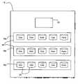
- FIG. 1there is shown a functional block diagram of an exemplary storage system 10 in which the invention can be implemented.
- the storage system 10includes one or more hosts 12 coupled to one or more storage arrays 14 .
- the storage arrays 14are shown coupled to each host 12 via a switch 16 ; however, the switch 16 may or may not be present.
- Each array 14includes groups 18 of storage devices 20 .
- the storage devices employed in the embodiments herein describedare disk drives, though the invention applies to all types of storage devices in all types of storage systems.
- the inventioncan be employed in file-based networks or block-level networks as well as the storage area network shown in FIG. 1 .
- each group 18Sufficient redundancy is provided in each group 18 to ensure that data can continue to be read from and written to the group 18 even after a limited number of disk drive failures.
- groups 18are found for example in RAID (“Redundant Array of Independent Disks”) arrays.
- RAIDRedundant Array of Independent Disks
- a group of y disksincludes m levels of redundancy, meaning that up to m failures can occur across the y disks with no loss of ability to transfer data to and from the group.
- a RAID level 4 groupconsists of data disks and one parity disk. The parity disk is used to store parity across the group, so that if one disk in the group fails, data transfers can continue to and from the group.
- y disks in a RAID level 4 arrayinclude one level of redundancy.
- data and redundant informationcan be distributed in a striped manner across all the y disks, and that the invention applies equally to such configurations.
- the redundant informationmay include parity, CRCs, ECC, or any other sort of error detection/correction information across the group. In this case, up to two disk failures can occur with no loss of ability to transfer data to and from the group.
- a disk “failure” as used hereinincludes any situation in which a read operation does not result in fully valid read data, or a write operation cannot be entirely completed.
- Such failuresinclude but are not limited to entire disk failures, or failures limited to a particular disk sector or disk location, or transient failures that prevent a particular read or write operation from validly completing. Some such failures are repairable.
- the disk(s)are selectively rebuilt—that is, the areas of the disk(s) on which the failures occurred are rebuilt as is known in the art in accordance with the redundancy protocol employed (e.g. RAID level 4 or RAID level 6), returning the group to full m level redundancy. For example, a failure occurring in one disk sector on a disk requires rebuilding of only the portion of the sector of the disk. If an entire failed disk is replaced, the new disk must be completely rebuilt.
- RAID algorithmsare important to implement in order to protect the data against disk failures.
- the inventiontakes advantage of the redundancy provided by a RAID group to save power and extend drive life.
- the inventiontakes notice of the fact that not all disks in a RAID group are required to be spun up in order to perform data transfers.
- RAID groupscan suffer failures of a number of drives equal to the number of levels of redundancy with no loss of ability to transfer data to and from the RAID group. For example, in a RAID level 4 group, data transfers can continue after one drive failure occurs. In a RAID level 6 group, data transfers can continue after two drive failures occur.
- Some RAID groups 18sit idle or are subject to minimal write activity at certain times; for example, during backup operations when the RAID group is the source of the backup, or during decision support system (DSS) or data mining operations. The invention realizes that during such times, data transfer operations can occur successfully without full RAID redundancy; thus, not all the drives in all the RAID groups need be spun up.
- DSSdecision support system
- the inventionis first described as it applies to a simple RAID level 4 array including RAID 4+1 groups. It is then described as it applies in the more general case of a RAID group including y disks incorporating m levels of redundancy.
- FIG. 2there is shown an example of a RAID level 4 array.
- the array 14is shown to include an array controller 22 and multiple RAID groups 18 of disk drives 20 , herein shown as three RAID 4+1 groups 18 a , 18 b and 18 c .
- Each group 18 of disks 20includes four data disks and one parity disk. Whenever data is written to a group 18 , parity is calculated across the data and written to the parity disk. In the event of a disk 20 failure in the group 18 , the parity information can be used to recover all the data previously written to the group 18 . When a failed data disk is recovered, the data disk is rebuilt as required.
- the storage array 14enters a power save mode during which, for each RAID group 18 , one disk drive 20 in the RAID group 18 is spun down for a period of time. Data transfer operations are performed by accessing the remaining drives in the RAID group 18 . After the period of time expires, the disk 20 is spun back up and rebuilt where required, and another disk 20 in the group is spun down. This cycle continues until it is necessary to have all disks 20 in the array spun up, at which time the power save mode is disabled.
- Appropriate times for performing the spin down operationsinclude for example array or group idle time, and time during which only backup or archiving operations are occurring on a source array or group. The times can be set by a user, or automatically detected by the array 14 .
- FIG. 3The process by which this embodiment of the invention operates is shown in detail in FIG. 3 .
- the process of FIG. 3is preferably executed by the array controller 22 for each RAID group 18 in the array 14 . That is, the array controller 22 preferably employs one instance of the process of FIG. 3 for each RAID group 18 a, b , and c .
- the array controller 22employs a timer t.
- the timer tmeasures the amount of time a disk 20 should remain spun down, and can vary based on design requirements. In one embodiment, a reasonable time t is about 8 hours.
- the controller 22monitors to detect whether a “power save mode” has been entered (step 32 ).
- Power save modemay be entered for all RAID groups 18 , or separately for one or more RAID groups 18 .
- the power save modeis preferably entered during periods of low or no data write activity.
- the array controller 22can determine whether to enter power save mode. For instance, when a backup or archiving process is launched for a source array 14 , it is likely that one or more RAID groups 18 are not otherwise being used, therefore power save mode may be entered in response to the start of the backup process. Alternatively, if no write activity is detected for a certain minimum amount of time, for example 30 minutes, power save mode could be entered, and then disabled if substantial write activity occurs.
- step 34Once power save mode is initially entered for a given RAID group 18 (step 32 ), the timer t is reset (step 34 ). A first disk in then spun down (step 36 ). Power save mode is checked again (step 38 ), and if it is still enabled, then the array controller 22 checks to see if a policy spinup is indicated. If a policy spinup is indicated, the array controller 22 proceeds to spin up the disk (step 42 ). If writes to the group have occurred, the array controller 22 rebuilds the disk as needed. If power save mode is still enabled (step 32 ), then the next disk 20 is spun down (steps 34 , 36 ). This process repeats so that each disk 20 in the group 18 is successively spun down and then later spun back up, until power save mode is disabled in accordance with a spin up policy.
- the spin up policy of step 40is applied to determine whether to spin up the spun down disk 20 .
- the spin up policycan consider many different factors in this determination. For example, the policy can cause the disk to spin up after writes to the disk are detected, or after a certain threshold of writes has been exceeded, or after a backup process is terminated, or after a disk failure has occurred.
- the spin up policycould also cause the disk to spin up if a rebuild threshold has been exceeded. That is, if a disk suffers multiple errors to the point where a threshold number of rebuild operations is exceeded, the spun down disk might be spun up.
- the spin up policycould cause the disk to spin up if an I/O performance service level is not being met.
- a timer tis associated with each spun down disk.
- FIG. 3is one of many ways in which the general process of the invention can be implemented.
- One skilled in the artwill understand that modifications can be made to optimize design considerations. For example, one might choose to spin down the same disk every time power save mode is entered, rather than starting with the next one in line.
- write operations occurring during power save modeare cached.
- RAID arrayssuch as array 14 include caches for caching data before writing it to the disk drives.
- Cache datais typically stored in a non-volatile memory, or in volatile memory in a system with sufficient battery power to write all data back to disk before shutting down. Therefore, any data written during a power interruption is not at risk of being lost.
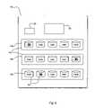
- FIG. 4the array 14 of FIG. 2 is shown now further including a cache 50 .
- the array controller 22operates to support this functionality is shown in FIG. 5 .
- step 52If power save mode is enabled (step 52 ), and then a write operation occurs (step 54 ), the write is cached (step 56 ). Write caching continues until power save mode is disabled (step 58 ). When write caching is used, one of the policies by which power save mode is disabled monitors the write rate to the RAID group 18 , or monitors the fullness of the cache 50 . If the cache 50 is close to full, power save mode is disabled. When power save mode is disabled, the group 18 is updated by writing the cached data to the disks in the group (step 60 ).
- FIG. 6there is shown a representation of the array 14 of FIG. 4 during power save mode.
- each RAID group 18one of the disks 20 is spun down, as indicated by an “X”. Note that, though the controller 18 operates on the RAID groups 18 one disk 20 at a time in order, the operations on the RAID groups 18 do not necessarily occur synchronously, so different disks 20 in each group 18 may be spun down at the same time. Furthermore, disks 20 in each group 18 may be spun down sequentially or in any desired order as design requirements dictate.
- each group of y disksmay have a different value of m; that is, one group of y disks may have two levels of redundancy while another group of y disk has one.
- the redundant informationis spread across all y disks, as in a RAID level 5 implementation. In other cases, certain disks in a group store data while others store redundant information.
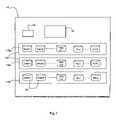
- FIG. 7there is shown a storage array 14 including groups 118 of disk drives 20 .
- Each group 118includes y disk drives.
- the y disk drivesinclude n data storage devices and m redundant storage devices, that is, m levels of redundancy are employed across the y disks.
- Each group 118has its own value of n and m.
- a group 118 a in FIG. 7is shown to include data disks Data( 1 )—Data(n 1 ), and redundant disks R( 1 )-R(m 1 ). In this case, data transfers can be performed successfully to the group 118 a in light of up to and including m 1 disk drive failures.
- a group 118 b in FIG. 7is shown to include data disks Data( 1 )-Data(n 2 ), and redundant disks R( 1 )-R(m 2 ).
- data transferscan be performed successfully to the group 118 a in light of up to and including m 2 disk drive failures.
- One example of such an array 14is a RAID level 6 array including several RAID 4+2 groups.
- the invention as applied to the general casecan be embodied in several ways, depending upon the level of failure protection required.
- FIG. 8there is shown a flow diagram of one embodiment of the invention.
- This embodimentgeneralizes the case of FIG. 3 by spinning down m disks 20 during power save mode.
- any two data or redundant drivescan be spun down without loss of data transfer functionality.
- the process of FIG. 8is instantiated separately for each group in the array, and thus it is understood that m may be different for each group.
- the processstarts by setting the value m to the number of levels of redundancy for the group (step 120 ).
- a timer tis reset (step 124 ) and m disks are spun down (step 126 ).
- the spin up policydoes not indicate that the m disks should be spun up (step 128 )
- the m disks 20remain spun down.
- writescan be performed during the process of FIG. 8 , but they will not be performed redundantly. So, the caching process of FIG. 5 can be employed in addition to the embodiment of FIG. 8 as previously described. If writes are cached, then at step 132 , the m disks are updated after being spun up.
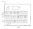
- FIG. 9a RAID level 6 array 14 is shown as the process of FIG. 8 is applied.
- Each RAID 4+2 group 24is shown as having two disks spun down. Again, the groups are operated upon independently.
- m levels of redundancyare provided during normal operation; that is, data transfers are completed successfully in light of up to any m disk failures.
- power save modeat least a single level of redundancy is provided.
- step 158the drives 20 remain spun down.
- FIG. 11a RAID level 6 array 14 is shown as the process of FIG. 10 is applied.
- Each RAID 4+2 group 118is shown as having one disk 20 spun down, leaving one redundant disk 20 per group 118 . Again, the groups are operated upon independently.
- each disk drive in each groupis separately controlled and responsive to its own spin-down timer and spin up policy decision.
- each RAID group 118may consist of a group of y disks including one or more standby spare disks that can be brought on-line to replace a failed disk in the group.
- the number of levels of redundancy availabletakes into account the number of invoked, fully rebuilt, spun-up, accessible spare disks available (hereinafter “spares”), and the number of currently failed disks in each group 118 .
- each group in a systemhas m levels of redundancy where m may differ for each group.
- Each groupmay consist of a different number of drives, and the groups may implement different RAID levels.
- each groupmay have a different value of m.
- Each groupmay include one or more stand-by spares, and each group may include one or more failed disks at any time.
- a number of disks p less than or equal to the value of m plus the number of spares minus the number of failed disksis chosen to represent the number of disks in a group that will be spun down (step 172 ).
- the controller 22then executes the process of FIG. 12 for each group; that is, if an array contains six groups of disk drives, then six instantiations of the process of FIG. 12 are executed.
- the value of mis set to the number of levels of redundancy for the group (step 170 ). Then, power save mode is monitored (step 172 ). When in power save mode, a number of current disk failures q in the group, and the number of stand-by spares r invoked for the group (step 174 ) are used to determine a value of p (step 176 ), wherein p is less than or equal to m ⁇ q+r. The value p is the maximum number of disks that will be spun down during power save mode for the current values of q and r. (step 172 ).
- step 178If power save mode is enabled, and fewer than p disks are not spun down (step 178 ), then one of the disks “n” is chosen to be spun down (step 180 ).
- a timer t_n, specific to the disk n,is set to 0 (step 182 ), and the disk n is spun down (step 183 ).
- step 184If a policy spin up is indicated (step 184 ), then one of the spun down disks is spun up (step 186 ) and the process returns to step 172 . If a policy spin up is not indicated, then the process returns to step 172 . From step 172 , q and p will again be evaluated in case either value has changed; thus, the value of p is dynamic.
- a policy spin upmay result in the spinning up of one or more disks at step 186 , depending on the particular policy invoked. For example, if p disks are spun down and a disk failure occurs, one disk may be spun up. If a write threshold is exceeded, all disks might be spun up. Furthermore, each of the p disks has its own spin down timer t_n, and each timer t_n may have a different timeout value spindown_time_n. If any timers t_n reach their timeout value spindown_time_n, a policy spin up is recognized at step 184 and that disk is spun up.
- the policy spin up decision at step 184can differ for each instantiation of the process of FIG. 132 .
- the spin up policy for the groupcan choose to spin up a disk based on a threshold number of failures.
- the policycan indicate which of the p disks to spin up based, for example, on how much rebuild might be required to bring a given disk back online. In this case, one or more disks would be spun up in accordance with the policy, while the others would remain spun down.
- FIG. 13there is shown an array 14 embodying the process of FIG. 12 .
- p3.
- p2.
- p1.
- FIG. 14there is shown another arrangement of an array 14 embodying the process of FIG. 12 .
- a single disk 20can be shared between multiple RAID groups.
- a single disk 20can be partitioned so that a first part of the disk 20 is associated with a RAID level 4 group, while a second part of the disk 20 is associated with a RAID level 6 group.
- the number of disks p to spin downmust take the various RAID levels into account, to ensure that the lowest level of redundancy is not compromised.
- Power savingsis achieved by spinning down disks 20 in the array 14 .
- the larger the array 14the greater the power savings.
- the lifetime of the drivecould be increased, leading to higher reliability and fewer repair calls.
Landscapes
- Engineering & Computer Science (AREA)
- Theoretical Computer Science (AREA)
- General Engineering & Computer Science (AREA)
- Physics & Mathematics (AREA)
- General Physics & Mathematics (AREA)
- Human Computer Interaction (AREA)
- Computer Hardware Design (AREA)
- Computing Systems (AREA)
- Techniques For Improving Reliability Of Storages (AREA)
Abstract
Description
Claims (25)
Priority Applications (1)
| Application Number | Priority Date | Filing Date | Title |
|---|---|---|---|
| US11/361,907US7516348B1 (en) | 2006-02-24 | 2006-02-24 | Selective power management of disk drives during semi-idle time in order to save power and increase drive life span |
Applications Claiming Priority (1)
| Application Number | Priority Date | Filing Date | Title |
|---|---|---|---|
| US11/361,907US7516348B1 (en) | 2006-02-24 | 2006-02-24 | Selective power management of disk drives during semi-idle time in order to save power and increase drive life span |
Publications (1)
| Publication Number | Publication Date |
|---|---|
| US7516348B1true US7516348B1 (en) | 2009-04-07 |
Family
ID=40512845
Family Applications (1)
| Application Number | Title | Priority Date | Filing Date |
|---|---|---|---|
| US11/361,907Active2027-03-19US7516348B1 (en) | 2006-02-24 | 2006-02-24 | Selective power management of disk drives during semi-idle time in order to save power and increase drive life span |
Country Status (1)
| Country | Link |
|---|---|
| US (1) | US7516348B1 (en) |
Cited By (55)
| Publication number | Priority date | Publication date | Assignee | Title |
|---|---|---|---|---|
| US20080007860A1 (en)* | 2006-07-04 | 2008-01-10 | Nec Corporation | Disk array control apparatus and method |
| US20080259710A1 (en)* | 2007-04-18 | 2008-10-23 | Dell Products L.P. | System and method for power management of storage resources |
| US20090083483A1 (en)* | 2007-09-24 | 2009-03-26 | International Business Machines Corporation | Power Conservation In A RAID Array |
| US20090100216A1 (en)* | 2007-10-12 | 2009-04-16 | Chunqi Han | Power saving optimization for disk drives with external cache |
| US20090125730A1 (en)* | 2007-11-08 | 2009-05-14 | International Business Machines Corporation | Managing Power Consumption In A Computer |
| US20090132842A1 (en)* | 2007-11-15 | 2009-05-21 | International Business Machines Corporation | Managing Computer Power Consumption In A Computer Equipment Rack |
| US20090138219A1 (en)* | 2007-11-28 | 2009-05-28 | International Business Machines Corporation | Estimating power consumption of computing components configured in a computing system |
| US20090177837A1 (en)* | 2008-01-03 | 2009-07-09 | Hitachi, Ltd. | Methods and apparatus for managing hdd's spin-down and spin-up in tiered storage systems |
| US20090217067A1 (en)* | 2008-02-27 | 2009-08-27 | Dell Products L.P. | Systems and Methods for Reducing Power Consumption in a Redundant Storage Array |
| US20090249104A1 (en)* | 2008-03-28 | 2009-10-01 | Hitachi, Ltd. | Storage system |
| US20090313431A1 (en)* | 2008-06-13 | 2009-12-17 | Hajime Takasugi | Disk Array Recording Apparatus and Recording Control Method Thereof |
| US20100083010A1 (en)* | 2008-10-01 | 2010-04-01 | International Business Machines Corporation | Power Management For Clusters Of Computers |
| US20100100664A1 (en)* | 2008-10-21 | 2010-04-22 | Hitachi, Ltd. | Storage system |
| US20100121892A1 (en)* | 2008-11-07 | 2010-05-13 | Hitachi, Ltd. | Storage system and management method of file system using the storage system |
| US20100118019A1 (en)* | 2008-11-12 | 2010-05-13 | International Business Machines Corporation | Dynamically Managing Power Consumption Of A Computer With Graphics Adapter Configurations |
| US20100174940A1 (en)* | 2009-01-07 | 2010-07-08 | Canon Kabushiki Kaisha | Information processing apparatus, method for controlling the information processing apparatus, and storage medium |
| US20110035605A1 (en)* | 2009-08-04 | 2011-02-10 | Mckean Brian | Method for optimizing performance and power usage in an archival storage system by utilizing massive array of independent disks (MAID) techniques and controlled replication under scalable hashing (CRUSH) |
| US20110252194A1 (en)* | 2008-11-17 | 2011-10-13 | Hitachi, Ltd | Storage control apparatus and storage control method |
| US8103884B2 (en) | 2008-06-25 | 2012-01-24 | International Business Machines Corporation | Managing power consumption of a computer |
| US20120140355A1 (en)* | 2010-12-07 | 2012-06-07 | International Business Machine Corporation | Reliability-Aware Disk Power Management |
| US20120250179A1 (en)* | 2011-03-30 | 2012-10-04 | Fujitsu Limited | Storage system, storage control apparatus, and storage control method |
| US8285747B1 (en)* | 2006-03-14 | 2012-10-09 | Netapp, Inc. | Incorporation of client storage into a storage system |
| US20150198995A1 (en)* | 2007-08-28 | 2015-07-16 | Commvault Systems, Inc. | Power management of data processing resources, such as power adaptive management of data storage operations |
| US9541978B2 (en) | 2014-06-13 | 2017-01-10 | Seagate Technology Llc | Redundancies for reconstruction in mass data storage systems |
| US20170192685A1 (en)* | 2016-01-06 | 2017-07-06 | HGST Netherlands B.V. | Variable-RPM Hard Disk Drive Control |
| US9720606B2 (en) | 2010-10-26 | 2017-08-01 | Avago Technologies General Ip (Singapore) Pte. Ltd. | Methods and structure for online migration of data in storage systems comprising a plurality of storage devices |
| US10075527B2 (en) | 2012-03-30 | 2018-09-11 | Commvault Systems, Inc. | Information management of data associated with multiple cloud services |
| US10289326B2 (en) | 2015-09-14 | 2019-05-14 | HGST Netherlands, B.V. | Optimized data layout for object store system |
| US10387273B2 (en) | 2016-09-16 | 2019-08-20 | Oracle International Corporation | Hierarchical fault tolerance in system storage |
| US10467172B2 (en) | 2016-06-01 | 2019-11-05 | Seagate Technology Llc | Interconnect for shared control electronics |
| US10705932B2 (en) | 2017-10-27 | 2020-07-07 | EMC IP Holding Company LLC | Method, device and computer program product for managing a storage system |
| US10891198B2 (en) | 2018-07-30 | 2021-01-12 | Commvault Systems, Inc. | Storing data to cloud libraries in cloud native formats |
| US11074138B2 (en) | 2017-03-29 | 2021-07-27 | Commvault Systems, Inc. | Multi-streaming backup operations for mailboxes |
| US11099944B2 (en) | 2012-12-28 | 2021-08-24 | Commvault Systems, Inc. | Storing metadata at a cloud-based data recovery center for disaster recovery testing and recovery of backup data stored remotely from the cloud-based data recovery center |
| US11108858B2 (en) | 2017-03-28 | 2021-08-31 | Commvault Systems, Inc. | Archiving mail servers via a simple mail transfer protocol (SMTP) server |
| US11221939B2 (en) | 2017-03-31 | 2022-01-11 | Commvault Systems, Inc. | Managing data from internet of things devices in a vehicle |
| US11269734B2 (en) | 2019-06-17 | 2022-03-08 | Commvault Systems, Inc. | Data storage management system for multi-cloud protection, recovery, and migration of databases-as-a-service and/or serverless database management systems |
| US11294786B2 (en) | 2017-03-31 | 2022-04-05 | Commvault Systems, Inc. | Management of internet of things devices |
| US11308035B2 (en) | 2009-06-30 | 2022-04-19 | Commvault Systems, Inc. | Data object store and server for a cloud storage environment, including data deduplication and data management across multiple cloud storage sites |
| US11314687B2 (en) | 2020-09-24 | 2022-04-26 | Commvault Systems, Inc. | Container data mover for migrating data between distributed data storage systems integrated with application orchestrators |
| US11314618B2 (en) | 2017-03-31 | 2022-04-26 | Commvault Systems, Inc. | Management of internet of things devices |
| US11321188B2 (en) | 2020-03-02 | 2022-05-03 | Commvault Systems, Inc. | Platform-agnostic containerized application data protection |
| US11366723B2 (en) | 2019-04-30 | 2022-06-21 | Commvault Systems, Inc. | Data storage management system for holistic protection and migration of serverless applications across multi-cloud computing environments |
| US11422900B2 (en) | 2020-03-02 | 2022-08-23 | Commvault Systems, Inc. | Platform-agnostic containerized application data protection |
| US11442768B2 (en) | 2020-03-12 | 2022-09-13 | Commvault Systems, Inc. | Cross-hypervisor live recovery of virtual machines |
| US11467753B2 (en) | 2020-02-14 | 2022-10-11 | Commvault Systems, Inc. | On-demand restore of virtual machine data |
| US11467863B2 (en) | 2019-01-30 | 2022-10-11 | Commvault Systems, Inc. | Cross-hypervisor live mount of backed up virtual machine data |
| US11500669B2 (en) | 2020-05-15 | 2022-11-15 | Commvault Systems, Inc. | Live recovery of virtual machines in a public cloud computing environment |
| US11561866B2 (en) | 2019-07-10 | 2023-01-24 | Commvault Systems, Inc. | Preparing containerized applications for backup using a backup services container and a backup services container-orchestration pod |
| US11604706B2 (en) | 2021-02-02 | 2023-03-14 | Commvault Systems, Inc. | Back up and restore related data on different cloud storage tiers |
| US12032855B2 (en) | 2021-08-06 | 2024-07-09 | Commvault Systems, Inc. | Using an application orchestrator computing environment for automatically scaled deployment of data protection resources needed for data in a production cluster distinct from the application orchestrator or in another application orchestrator computing environment |
| US12093546B2 (en) | 2021-03-02 | 2024-09-17 | Seagate Technology Llc | Operating multiple storage devices using NVM interface |
| US12130708B2 (en) | 2020-07-10 | 2024-10-29 | Commvault Systems, Inc. | Cloud-based air-gapped data storage management system |
| US12135618B2 (en) | 2022-07-11 | 2024-11-05 | Commvault Systems, Inc. | Protecting configuration data in a clustered container system |
| US12380006B2 (en) | 2020-09-22 | 2025-08-05 | Commvault Systems, Inc. | Anti-entropy-based metadata recovery in a strongly consistent distributed data storage system |
Citations (8)
| Publication number | Priority date | Publication date | Assignee | Title |
|---|---|---|---|---|
| US5423046A (en)* | 1992-12-17 | 1995-06-06 | International Business Machines Corporation | High capacity data storage system using disk array |
| US20020199129A1 (en)* | 2001-06-21 | 2002-12-26 | International Business Machines Corp. | Data storage on a computer disk array |
| US20050154962A1 (en) | 2003-12-30 | 2005-07-14 | Grover Andrew S. | Method and system to spin up a hard disk prior to a hard disk data exchange request |
| US6959399B2 (en) | 2001-09-24 | 2005-10-25 | International Business Machines Corporation | Selective automated power cycling of faulty disk in intelligent disk array enclosure for error recovery |
| US6961815B2 (en) | 2002-12-05 | 2005-11-01 | International Business Machines Corporation | Multiple disk data storage system for reducing power consumption |
| US7035972B2 (en) | 2002-09-03 | 2006-04-25 | Copan Systems, Inc. | Method and apparatus for power-efficient high-capacity scalable storage system |
| US7234074B2 (en) | 2003-12-17 | 2007-06-19 | International Business Machines Corporation | Multiple disk data storage system for reducing power consumption |
| US7380088B2 (en)* | 2005-02-04 | 2008-05-27 | Dot Hill Systems Corp. | Storage device method and apparatus |
- 2006
- 2006-02-24USUS11/361,907patent/US7516348B1/enactiveActive
Patent Citations (8)
| Publication number | Priority date | Publication date | Assignee | Title |
|---|---|---|---|---|
| US5423046A (en)* | 1992-12-17 | 1995-06-06 | International Business Machines Corporation | High capacity data storage system using disk array |
| US20020199129A1 (en)* | 2001-06-21 | 2002-12-26 | International Business Machines Corp. | Data storage on a computer disk array |
| US6959399B2 (en) | 2001-09-24 | 2005-10-25 | International Business Machines Corporation | Selective automated power cycling of faulty disk in intelligent disk array enclosure for error recovery |
| US7035972B2 (en) | 2002-09-03 | 2006-04-25 | Copan Systems, Inc. | Method and apparatus for power-efficient high-capacity scalable storage system |
| US6961815B2 (en) | 2002-12-05 | 2005-11-01 | International Business Machines Corporation | Multiple disk data storage system for reducing power consumption |
| US7234074B2 (en) | 2003-12-17 | 2007-06-19 | International Business Machines Corporation | Multiple disk data storage system for reducing power consumption |
| US20050154962A1 (en) | 2003-12-30 | 2005-07-14 | Grover Andrew S. | Method and system to spin up a hard disk prior to a hard disk data exchange request |
| US7380088B2 (en)* | 2005-02-04 | 2008-05-27 | Dot Hill Systems Corp. | Storage device method and apparatus |
Cited By (102)
| Publication number | Priority date | Publication date | Assignee | Title |
|---|---|---|---|---|
| US8285747B1 (en)* | 2006-03-14 | 2012-10-09 | Netapp, Inc. | Incorporation of client storage into a storage system |
| US20080007860A1 (en)* | 2006-07-04 | 2008-01-10 | Nec Corporation | Disk array control apparatus and method |
| US20080259710A1 (en)* | 2007-04-18 | 2008-10-23 | Dell Products L.P. | System and method for power management of storage resources |
| US8707076B2 (en)* | 2007-04-18 | 2014-04-22 | Dell Products L.P. | System and method for power management of storage resources |
| US8959375B2 (en) | 2007-04-18 | 2015-02-17 | Dell Products L.P. | System and method for power management of storage resources |
| US10379598B2 (en)* | 2007-08-28 | 2019-08-13 | Commvault Systems, Inc. | Power management of data processing resources, such as power adaptive management of data storage operations |
| US20150198995A1 (en)* | 2007-08-28 | 2015-07-16 | Commvault Systems, Inc. | Power management of data processing resources, such as power adaptive management of data storage operations |
| US20090083483A1 (en)* | 2007-09-24 | 2009-03-26 | International Business Machines Corporation | Power Conservation In A RAID Array |
| US20090100216A1 (en)* | 2007-10-12 | 2009-04-16 | Chunqi Han | Power saving optimization for disk drives with external cache |
| US8495276B2 (en)* | 2007-10-12 | 2013-07-23 | HGST Netherlands B.V. | Power saving optimization for disk drives with external cache |
| US20090125730A1 (en)* | 2007-11-08 | 2009-05-14 | International Business Machines Corporation | Managing Power Consumption In A Computer |
| US8166326B2 (en) | 2007-11-08 | 2012-04-24 | International Business Machines Corporation | Managing power consumption in a computer |
| US20090132842A1 (en)* | 2007-11-15 | 2009-05-21 | International Business Machines Corporation | Managing Computer Power Consumption In A Computer Equipment Rack |
| US20090138219A1 (en)* | 2007-11-28 | 2009-05-28 | International Business Machines Corporation | Estimating power consumption of computing components configured in a computing system |
| US8041521B2 (en) | 2007-11-28 | 2011-10-18 | International Business Machines Corporation | Estimating power consumption of computing components configured in a computing system |
| US20090177837A1 (en)* | 2008-01-03 | 2009-07-09 | Hitachi, Ltd. | Methods and apparatus for managing hdd's spin-down and spin-up in tiered storage systems |
| US8140754B2 (en)* | 2008-01-03 | 2012-03-20 | Hitachi, Ltd. | Methods and apparatus for managing HDD's spin-down and spin-up in tiered storage systems |
| US20090217067A1 (en)* | 2008-02-27 | 2009-08-27 | Dell Products L.P. | Systems and Methods for Reducing Power Consumption in a Redundant Storage Array |
| US20090249104A1 (en)* | 2008-03-28 | 2009-10-01 | Hitachi, Ltd. | Storage system |
| US8032775B2 (en)* | 2008-03-28 | 2011-10-04 | Hitachi, Ltd. | Storage system |
| US20090313431A1 (en)* | 2008-06-13 | 2009-12-17 | Hajime Takasugi | Disk Array Recording Apparatus and Recording Control Method Thereof |
| US8103884B2 (en) | 2008-06-25 | 2012-01-24 | International Business Machines Corporation | Managing power consumption of a computer |
| US20100083010A1 (en)* | 2008-10-01 | 2010-04-01 | International Business Machines Corporation | Power Management For Clusters Of Computers |
| US8041976B2 (en) | 2008-10-01 | 2011-10-18 | International Business Machines Corporation | Power management for clusters of computers |
| US20100100664A1 (en)* | 2008-10-21 | 2010-04-22 | Hitachi, Ltd. | Storage system |
| JP2010102369A (en)* | 2008-10-21 | 2010-05-06 | Hitachi Ltd | Storage system |
| US20100121892A1 (en)* | 2008-11-07 | 2010-05-13 | Hitachi, Ltd. | Storage system and management method of file system using the storage system |
| US8667030B2 (en)* | 2008-11-07 | 2014-03-04 | Hitachi, Ltd. | Storage system and management method of file system using the storage system |
| US8514215B2 (en) | 2008-11-12 | 2013-08-20 | International Business Machines Corporation | Dynamically managing power consumption of a computer with graphics adapter configurations |
| US20100118019A1 (en)* | 2008-11-12 | 2010-05-13 | International Business Machines Corporation | Dynamically Managing Power Consumption Of A Computer With Graphics Adapter Configurations |
| US20110252194A1 (en)* | 2008-11-17 | 2011-10-13 | Hitachi, Ltd | Storage control apparatus and storage control method |
| US8285928B2 (en)* | 2008-11-17 | 2012-10-09 | Hitachi, Ltd. | Storage control apparatus and storage control method for recovering data in a failed storage device of a RAID sysytem |
| US8312313B2 (en)* | 2009-01-07 | 2012-11-13 | Canon Kabushiki Kaisha | Information processing apparatus, method for controlling the information processing apparatus, and storage medium |
| US20100174940A1 (en)* | 2009-01-07 | 2010-07-08 | Canon Kabushiki Kaisha | Information processing apparatus, method for controlling the information processing apparatus, and storage medium |
| US11907168B2 (en) | 2009-06-30 | 2024-02-20 | Commvault Systems, Inc. | Data object store and server for a cloud storage environment, including data deduplication and data management across multiple cloud storage sites |
| US12321592B2 (en) | 2009-06-30 | 2025-06-03 | Commvault Systems, Inc. | Data object store and server for a cloud storage environment |
| US11308035B2 (en) | 2009-06-30 | 2022-04-19 | Commvault Systems, Inc. | Data object store and server for a cloud storage environment, including data deduplication and data management across multiple cloud storage sites |
| US20110035605A1 (en)* | 2009-08-04 | 2011-02-10 | Mckean Brian | Method for optimizing performance and power usage in an archival storage system by utilizing massive array of independent disks (MAID) techniques and controlled replication under scalable hashing (CRUSH) |
| US8201001B2 (en)* | 2009-08-04 | 2012-06-12 | Lsi Corporation | Method for optimizing performance and power usage in an archival storage system by utilizing massive array of independent disks (MAID) techniques and controlled replication under scalable hashing (CRUSH) |
| US9720606B2 (en) | 2010-10-26 | 2017-08-01 | Avago Technologies General Ip (Singapore) Pte. Ltd. | Methods and structure for online migration of data in storage systems comprising a plurality of storage devices |
| CN102566737B (en)* | 2010-12-07 | 2014-12-17 | 国际商业机器公司 | Method and system for reliability-aware disk power management |
| US8677162B2 (en)* | 2010-12-07 | 2014-03-18 | International Business Machines Corporation | Reliability-aware disk power management |
| CN102566737A (en)* | 2010-12-07 | 2012-07-11 | 国际商业机器公司 | Method and system for reliability-aware disk power management |
| US20120140355A1 (en)* | 2010-12-07 | 2012-06-07 | International Business Machine Corporation | Reliability-Aware Disk Power Management |
| US8634156B2 (en)* | 2011-03-30 | 2014-01-21 | Fujitsu Limited | Storage system, storage control apparatus, and storage control method |
| US20120250179A1 (en)* | 2011-03-30 | 2012-10-04 | Fujitsu Limited | Storage system, storage control apparatus, and storage control method |
| US10264074B2 (en) | 2012-03-30 | 2019-04-16 | Commvault Systems, Inc. | Information management of data associated with multiple cloud services |
| US10999373B2 (en) | 2012-03-30 | 2021-05-04 | Commvault Systems, Inc. | Information management of data associated with multiple cloud services |
| US10075527B2 (en) | 2012-03-30 | 2018-09-11 | Commvault Systems, Inc. | Information management of data associated with multiple cloud services |
| US11956310B2 (en) | 2012-03-30 | 2024-04-09 | Commvault Systems, Inc. | Information management of data associated with multiple cloud services |
| US10547684B2 (en) | 2012-03-30 | 2020-01-28 | Commvault Systems, Inc. | Information management of data associated with multiple cloud services |
| US11099944B2 (en) | 2012-12-28 | 2021-08-24 | Commvault Systems, Inc. | Storing metadata at a cloud-based data recovery center for disaster recovery testing and recovery of backup data stored remotely from the cloud-based data recovery center |
| US9541978B2 (en) | 2014-06-13 | 2017-01-10 | Seagate Technology Llc | Redundancies for reconstruction in mass data storage systems |
| US10152105B2 (en) | 2014-06-13 | 2018-12-11 | Seagate Technology Llc | Common controller operating multiple storage drives |
| US9939865B2 (en) | 2014-06-13 | 2018-04-10 | Seagate Technology Llc | Selective storage resource powering for data transfer management |
| US9880602B2 (en) | 2014-06-13 | 2018-01-30 | Seagate Technology Llc | Power characteristics in a system of disparate storage drives |
| US9965011B2 (en) | 2014-06-13 | 2018-05-08 | Seagate Technology Llc | Controller interface for operation of multiple storage drives |
| US9874915B2 (en) | 2014-06-13 | 2018-01-23 | Seagate Technology Llc | Extended file attributes for redundant data storage |
| US10289326B2 (en) | 2015-09-14 | 2019-05-14 | HGST Netherlands, B.V. | Optimized data layout for object store system |
| US20170192685A1 (en)* | 2016-01-06 | 2017-07-06 | HGST Netherlands B.V. | Variable-RPM Hard Disk Drive Control |
| US10073625B2 (en)* | 2016-01-06 | 2018-09-11 | HGST Netherlands B.V. | Variable-RPM hard disk drive control |
| US10467172B2 (en) | 2016-06-01 | 2019-11-05 | Seagate Technology Llc | Interconnect for shared control electronics |
| US10387273B2 (en) | 2016-09-16 | 2019-08-20 | Oracle International Corporation | Hierarchical fault tolerance in system storage |
| US11108858B2 (en) | 2017-03-28 | 2021-08-31 | Commvault Systems, Inc. | Archiving mail servers via a simple mail transfer protocol (SMTP) server |
| US11074138B2 (en) | 2017-03-29 | 2021-07-27 | Commvault Systems, Inc. | Multi-streaming backup operations for mailboxes |
| US11221939B2 (en) | 2017-03-31 | 2022-01-11 | Commvault Systems, Inc. | Managing data from internet of things devices in a vehicle |
| US12316490B2 (en) | 2017-03-31 | 2025-05-27 | Commvault Systems, Inc. | Managing data from internet of things (IoT) devices |
| US11314618B2 (en) | 2017-03-31 | 2022-04-26 | Commvault Systems, Inc. | Management of internet of things devices |
| US11294786B2 (en) | 2017-03-31 | 2022-04-05 | Commvault Systems, Inc. | Management of internet of things devices |
| US11853191B2 (en) | 2017-03-31 | 2023-12-26 | Commvault Systems, Inc. | Management of internet of things devices |
| US11704223B2 (en) | 2017-03-31 | 2023-07-18 | Commvault Systems, Inc. | Managing data from internet of things (IoT) devices in a vehicle |
| US10705932B2 (en) | 2017-10-27 | 2020-07-07 | EMC IP Holding Company LLC | Method, device and computer program product for managing a storage system |
| US10891198B2 (en) | 2018-07-30 | 2021-01-12 | Commvault Systems, Inc. | Storing data to cloud libraries in cloud native formats |
| US11467863B2 (en) | 2019-01-30 | 2022-10-11 | Commvault Systems, Inc. | Cross-hypervisor live mount of backed up virtual machine data |
| US11947990B2 (en) | 2019-01-30 | 2024-04-02 | Commvault Systems, Inc. | Cross-hypervisor live-mount of backed up virtual machine data |
| US11366723B2 (en) | 2019-04-30 | 2022-06-21 | Commvault Systems, Inc. | Data storage management system for holistic protection and migration of serverless applications across multi-cloud computing environments |
| US11494273B2 (en) | 2019-04-30 | 2022-11-08 | Commvault Systems, Inc. | Holistically protecting serverless applications across one or more cloud computing environments |
| US11829256B2 (en) | 2019-04-30 | 2023-11-28 | Commvault Systems, Inc. | Data storage management system for holistic protection of cloud-based serverless applications in single cloud and across multi-cloud computing environments |
| US12197293B2 (en) | 2019-04-30 | 2025-01-14 | Commvault Systems, Inc. | Holistic protection of cloud-based serverless applications |
| US11269734B2 (en) | 2019-06-17 | 2022-03-08 | Commvault Systems, Inc. | Data storage management system for multi-cloud protection, recovery, and migration of databases-as-a-service and/or serverless database management systems |
| US11461184B2 (en) | 2019-06-17 | 2022-10-04 | Commvault Systems, Inc. | Data storage management system for protecting cloud-based data including on-demand protection, recovery, and migration of databases-as-a-service and/or serverless database management systems |
| US11989101B2 (en) | 2019-06-17 | 2024-05-21 | Commvault Systems, Inc. | Data storage management system for multi-cloud protection, recovery, and migration of databases-as-a-service (DBAAS) and/or serverless database management systems (DBMS) |
| US11561866B2 (en) | 2019-07-10 | 2023-01-24 | Commvault Systems, Inc. | Preparing containerized applications for backup using a backup services container and a backup services container-orchestration pod |
| US12007854B2 (en) | 2019-07-10 | 2024-06-11 | Commvault Systems, Inc. | Backup of containerized applications using a backup services container and a backup services container-orchestration pod |
| US11467753B2 (en) | 2020-02-14 | 2022-10-11 | Commvault Systems, Inc. | On-demand restore of virtual machine data |
| US11714568B2 (en) | 2020-02-14 | 2023-08-01 | Commvault Systems, Inc. | On-demand restore of virtual machine data |
| US11422900B2 (en) | 2020-03-02 | 2022-08-23 | Commvault Systems, Inc. | Platform-agnostic containerized application data protection |
| US11321188B2 (en) | 2020-03-02 | 2022-05-03 | Commvault Systems, Inc. | Platform-agnostic containerized application data protection |
| US11442768B2 (en) | 2020-03-12 | 2022-09-13 | Commvault Systems, Inc. | Cross-hypervisor live recovery of virtual machines |
| US11748143B2 (en) | 2020-05-15 | 2023-09-05 | Commvault Systems, Inc. | Live mount of virtual machines in a public cloud computing environment |
| US12086624B2 (en) | 2020-05-15 | 2024-09-10 | Commvault Systems, Inc. | Live recovery of virtual machines in a public cloud computing environment based on temporary live mount |
| US11500669B2 (en) | 2020-05-15 | 2022-11-15 | Commvault Systems, Inc. | Live recovery of virtual machines in a public cloud computing environment |
| US12130708B2 (en) | 2020-07-10 | 2024-10-29 | Commvault Systems, Inc. | Cloud-based air-gapped data storage management system |
| US12380006B2 (en) | 2020-09-22 | 2025-08-05 | Commvault Systems, Inc. | Anti-entropy-based metadata recovery in a strongly consistent distributed data storage system |
| US12007940B2 (en) | 2020-09-24 | 2024-06-11 | Commvault Systems, Inc. | Container data mover for migrating data between distributed data storage systems integrated with application orchestrators |
| US11314687B2 (en) | 2020-09-24 | 2022-04-26 | Commvault Systems, Inc. | Container data mover for migrating data between distributed data storage systems integrated with application orchestrators |
| US12367177B2 (en) | 2020-09-24 | 2025-07-22 | Commvault Systems, Inc. | Migrating data between data storage systems integrated with application orchestrators |
| US11604706B2 (en) | 2021-02-02 | 2023-03-14 | Commvault Systems, Inc. | Back up and restore related data on different cloud storage tiers |
| US12339747B2 (en) | 2021-02-02 | 2025-06-24 | Commvault Systems, Inc. | Back up and restore related data on different cloud storage tiers |
| US12093546B2 (en) | 2021-03-02 | 2024-09-17 | Seagate Technology Llc | Operating multiple storage devices using NVM interface |
| US12032855B2 (en) | 2021-08-06 | 2024-07-09 | Commvault Systems, Inc. | Using an application orchestrator computing environment for automatically scaled deployment of data protection resources needed for data in a production cluster distinct from the application orchestrator or in another application orchestrator computing environment |
| US12135618B2 (en) | 2022-07-11 | 2024-11-05 | Commvault Systems, Inc. | Protecting configuration data in a clustered container system |
Similar Documents
| Publication | Publication Date | Title |
|---|---|---|
| US7516348B1 (en) | Selective power management of disk drives during semi-idle time in order to save power and increase drive life span | |
| US7543178B2 (en) | Low cost RAID with seamless disk failure recovery | |
| US7434097B2 (en) | Method and apparatus for efficient fault-tolerant disk drive replacement in raid storage systems | |
| JP5768587B2 (en) | Storage system, storage control device, and storage control method | |
| US5655150A (en) | Recording device having alternative recording units operated in three different conditions depending on activities in maintenance diagnosis mechanism and recording sections | |
| US8392752B2 (en) | Selective recovery and aggregation technique for two storage apparatuses of a raid | |
| JP3078972B2 (en) | Disk array device | |
| US8464094B2 (en) | Disk array system and control method thereof | |
| JP5887757B2 (en) | Storage system, storage control device, and storage control method | |
| US7739544B2 (en) | Disk array system and rebuild method thereof | |
| US20060075283A1 (en) | Method and apparatus for just in time RAID spare drive pool management | |
| US7805633B2 (en) | Optimized reconstruction and copyback methodology for a disconnected drive in the presence of a global hot spare disk | |
| JP2004118837A (en) | Method for storing data in fault tolerance storage sub-system, the storage sub-system and data formation management program for the system | |
| US20040250017A1 (en) | Method and apparatus for selecting among multiple data reconstruction techniques | |
| US7721143B2 (en) | Method for reducing rebuild time on a RAID device | |
| JP2010015195A (en) | Storage controller and storage control method | |
| US10210062B2 (en) | Data storage system comprising an array of drives | |
| US7426655B2 (en) | System and method of enhancing storage array read performance using a spare storage array | |
| US20060090098A1 (en) | Proactive data reliability in a power-managed storage system | |
| US20070088990A1 (en) | System and method for reduction of rebuild time in raid systems through implementation of striped hot spare drives | |
| CN109032513B (en) | RAID (redundant array of independent disks) architecture based on SSD (solid State disk) and HDD (hard disk drive) and backup and reconstruction methods thereof | |
| US7310745B2 (en) | Efficient media scan operations for storage systems | |
| US20050210318A1 (en) | System and method for drive recovery following a drive failure | |
| JP4698710B2 (en) | Storage system and power saving method thereof | |
| US20100180131A1 (en) | Power management mechanism for data storage environment |
Legal Events
| Date | Code | Title | Description |
|---|---|---|---|
| AS | Assignment | Owner name:EMC CORPORATION, MASSACHUSETTS Free format text:ASSIGNMENT OF ASSIGNORS INTEREST;ASSIGNOR:OFER, ADI;REEL/FRAME:017616/0589 Effective date:20060221 | |
| STCF | Information on status: patent grant | Free format text:PATENTED CASE | |
| FEPP | Fee payment procedure | Free format text:PAYOR NUMBER ASSIGNED (ORIGINAL EVENT CODE: ASPN); ENTITY STATUS OF PATENT OWNER: LARGE ENTITY | |
| FPAY | Fee payment | Year of fee payment:4 | |
| AS | Assignment | Owner name:CREDIT SUISSE AG, CAYMAN ISLANDS BRANCH, AS COLLATERAL AGENT, NORTH CAROLINA Free format text:SECURITY AGREEMENT;ASSIGNORS:ASAP SOFTWARE EXPRESS, INC.;AVENTAIL LLC;CREDANT TECHNOLOGIES, INC.;AND OTHERS;REEL/FRAME:040134/0001 Effective date:20160907 Owner name:THE BANK OF NEW YORK MELLON TRUST COMPANY, N.A., AS NOTES COLLATERAL AGENT, TEXAS Free format text:SECURITY AGREEMENT;ASSIGNORS:ASAP SOFTWARE EXPRESS, INC.;AVENTAIL LLC;CREDANT TECHNOLOGIES, INC.;AND OTHERS;REEL/FRAME:040136/0001 Effective date:20160907 Owner name:CREDIT SUISSE AG, CAYMAN ISLANDS BRANCH, AS COLLAT Free format text:SECURITY AGREEMENT;ASSIGNORS:ASAP SOFTWARE EXPRESS, INC.;AVENTAIL LLC;CREDANT TECHNOLOGIES, INC.;AND OTHERS;REEL/FRAME:040134/0001 Effective date:20160907 Owner name:THE BANK OF NEW YORK MELLON TRUST COMPANY, N.A., A Free format text:SECURITY AGREEMENT;ASSIGNORS:ASAP SOFTWARE EXPRESS, INC.;AVENTAIL LLC;CREDANT TECHNOLOGIES, INC.;AND OTHERS;REEL/FRAME:040136/0001 Effective date:20160907 | |
| AS | Assignment | Owner name:EMC IP HOLDING COMPANY LLC, MASSACHUSETTS Free format text:ASSIGNMENT OF ASSIGNORS INTEREST;ASSIGNOR:EMC CORPORATION;REEL/FRAME:040203/0001 Effective date:20160906 | |
| FPAY | Fee payment | Year of fee payment:8 | |
| AS | Assignment | Owner name:THE BANK OF NEW YORK MELLON TRUST COMPANY, N.A., T Free format text:SECURITY AGREEMENT;ASSIGNORS:CREDANT TECHNOLOGIES, INC.;DELL INTERNATIONAL L.L.C.;DELL MARKETING L.P.;AND OTHERS;REEL/FRAME:049452/0223 Effective date:20190320 Owner name:THE BANK OF NEW YORK MELLON TRUST COMPANY, N.A., TEXAS Free format text:SECURITY AGREEMENT;ASSIGNORS:CREDANT TECHNOLOGIES, INC.;DELL INTERNATIONAL L.L.C.;DELL MARKETING L.P.;AND OTHERS;REEL/FRAME:049452/0223 Effective date:20190320 | |
| AS | Assignment | Owner name:THE BANK OF NEW YORK MELLON TRUST COMPANY, N.A., TEXAS Free format text:SECURITY AGREEMENT;ASSIGNORS:CREDANT TECHNOLOGIES INC.;DELL INTERNATIONAL L.L.C.;DELL MARKETING L.P.;AND OTHERS;REEL/FRAME:053546/0001 Effective date:20200409 | |
| MAFP | Maintenance fee payment | Free format text:PAYMENT OF MAINTENANCE FEE, 12TH YEAR, LARGE ENTITY (ORIGINAL EVENT CODE: M1553); ENTITY STATUS OF PATENT OWNER: LARGE ENTITY Year of fee payment:12 | |
| AS | Assignment | Owner name:WYSE TECHNOLOGY L.L.C., CALIFORNIA Free format text:RELEASE BY SECURED PARTY;ASSIGNOR:CREDIT SUISSE AG, CAYMAN ISLANDS BRANCH;REEL/FRAME:058216/0001 Effective date:20211101 Owner name:SCALEIO LLC, MASSACHUSETTS Free format text:RELEASE BY SECURED PARTY;ASSIGNOR:CREDIT SUISSE AG, CAYMAN ISLANDS BRANCH;REEL/FRAME:058216/0001 Effective date:20211101 Owner name:MOZY, INC., WASHINGTON Free format text:RELEASE BY SECURED PARTY;ASSIGNOR:CREDIT SUISSE AG, CAYMAN ISLANDS BRANCH;REEL/FRAME:058216/0001 Effective date:20211101 Owner name:MAGINATICS LLC, CALIFORNIA Free format text:RELEASE BY SECURED PARTY;ASSIGNOR:CREDIT SUISSE AG, CAYMAN ISLANDS BRANCH;REEL/FRAME:058216/0001 Effective date:20211101 Owner name:FORCE10 NETWORKS, INC., CALIFORNIA Free format text:RELEASE BY SECURED PARTY;ASSIGNOR:CREDIT SUISSE AG, CAYMAN ISLANDS BRANCH;REEL/FRAME:058216/0001 Effective date:20211101 Owner name:EMC IP HOLDING COMPANY LLC, TEXAS Free format text:RELEASE BY SECURED PARTY;ASSIGNOR:CREDIT SUISSE AG, CAYMAN ISLANDS BRANCH;REEL/FRAME:058216/0001 Effective date:20211101 Owner name:EMC CORPORATION, MASSACHUSETTS Free format text:RELEASE BY SECURED PARTY;ASSIGNOR:CREDIT SUISSE AG, CAYMAN ISLANDS BRANCH;REEL/FRAME:058216/0001 Effective date:20211101 Owner name:DELL SYSTEMS CORPORATION, TEXAS Free format text:RELEASE BY SECURED PARTY;ASSIGNOR:CREDIT SUISSE AG, CAYMAN ISLANDS BRANCH;REEL/FRAME:058216/0001 Effective date:20211101 Owner name:DELL SOFTWARE INC., CALIFORNIA Free format text:RELEASE BY SECURED PARTY;ASSIGNOR:CREDIT SUISSE AG, CAYMAN ISLANDS BRANCH;REEL/FRAME:058216/0001 Effective date:20211101 Owner name:DELL PRODUCTS L.P., TEXAS Free format text:RELEASE BY SECURED PARTY;ASSIGNOR:CREDIT SUISSE AG, CAYMAN ISLANDS BRANCH;REEL/FRAME:058216/0001 Effective date:20211101 Owner name:DELL MARKETING L.P., TEXAS Free format text:RELEASE BY SECURED PARTY;ASSIGNOR:CREDIT SUISSE AG, CAYMAN ISLANDS BRANCH;REEL/FRAME:058216/0001 Effective date:20211101 Owner name:DELL INTERNATIONAL, L.L.C., TEXAS Free format text:RELEASE BY SECURED PARTY;ASSIGNOR:CREDIT SUISSE AG, CAYMAN ISLANDS BRANCH;REEL/FRAME:058216/0001 Effective date:20211101 Owner name:DELL USA L.P., TEXAS Free format text:RELEASE BY SECURED PARTY;ASSIGNOR:CREDIT SUISSE AG, CAYMAN ISLANDS BRANCH;REEL/FRAME:058216/0001 Effective date:20211101 Owner name:CREDANT TECHNOLOGIES, INC., TEXAS Free format text:RELEASE BY SECURED PARTY;ASSIGNOR:CREDIT SUISSE AG, CAYMAN ISLANDS BRANCH;REEL/FRAME:058216/0001 Effective date:20211101 Owner name:AVENTAIL LLC, CALIFORNIA Free format text:RELEASE BY SECURED PARTY;ASSIGNOR:CREDIT SUISSE AG, CAYMAN ISLANDS BRANCH;REEL/FRAME:058216/0001 Effective date:20211101 Owner name:ASAP SOFTWARE EXPRESS, INC., ILLINOIS Free format text:RELEASE BY SECURED PARTY;ASSIGNOR:CREDIT SUISSE AG, CAYMAN ISLANDS BRANCH;REEL/FRAME:058216/0001 Effective date:20211101 | |
| AS | Assignment | Owner name:SCALEIO LLC, MASSACHUSETTS Free format text:RELEASE OF SECURITY INTEREST IN PATENTS PREVIOUSLY RECORDED AT REEL/FRAME (040136/0001);ASSIGNOR:THE BANK OF NEW YORK MELLON TRUST COMPANY, N.A., AS NOTES COLLATERAL AGENT;REEL/FRAME:061324/0001 Effective date:20220329 Owner name:EMC IP HOLDING COMPANY LLC (ON BEHALF OF ITSELF AND AS SUCCESSOR-IN-INTEREST TO MOZY, INC.), TEXAS Free format text:RELEASE OF SECURITY INTEREST IN PATENTS PREVIOUSLY RECORDED AT REEL/FRAME (040136/0001);ASSIGNOR:THE BANK OF NEW YORK MELLON TRUST COMPANY, N.A., AS NOTES COLLATERAL AGENT;REEL/FRAME:061324/0001 Effective date:20220329 Owner name:EMC CORPORATION (ON BEHALF OF ITSELF AND AS SUCCESSOR-IN-INTEREST TO MAGINATICS LLC), MASSACHUSETTS Free format text:RELEASE OF SECURITY INTEREST IN PATENTS PREVIOUSLY RECORDED AT REEL/FRAME (040136/0001);ASSIGNOR:THE BANK OF NEW YORK MELLON TRUST COMPANY, N.A., AS NOTES COLLATERAL AGENT;REEL/FRAME:061324/0001 Effective date:20220329 Owner name:DELL MARKETING CORPORATION (SUCCESSOR-IN-INTEREST TO FORCE10 NETWORKS, INC. AND WYSE TECHNOLOGY L.L.C.), TEXAS Free format text:RELEASE OF SECURITY INTEREST IN PATENTS PREVIOUSLY RECORDED AT REEL/FRAME (040136/0001);ASSIGNOR:THE BANK OF NEW YORK MELLON TRUST COMPANY, N.A., AS NOTES COLLATERAL AGENT;REEL/FRAME:061324/0001 Effective date:20220329 Owner name:DELL PRODUCTS L.P., TEXAS Free format text:RELEASE OF SECURITY INTEREST IN PATENTS PREVIOUSLY RECORDED AT REEL/FRAME (040136/0001);ASSIGNOR:THE BANK OF NEW YORK MELLON TRUST COMPANY, N.A., AS NOTES COLLATERAL AGENT;REEL/FRAME:061324/0001 Effective date:20220329 Owner name:DELL INTERNATIONAL L.L.C., TEXAS Free format text:RELEASE OF SECURITY INTEREST IN PATENTS PREVIOUSLY RECORDED AT REEL/FRAME (040136/0001);ASSIGNOR:THE BANK OF NEW YORK MELLON TRUST COMPANY, N.A., AS NOTES COLLATERAL AGENT;REEL/FRAME:061324/0001 Effective date:20220329 Owner name:DELL USA L.P., TEXAS Free format text:RELEASE OF SECURITY INTEREST IN PATENTS PREVIOUSLY RECORDED AT REEL/FRAME (040136/0001);ASSIGNOR:THE BANK OF NEW YORK MELLON TRUST COMPANY, N.A., AS NOTES COLLATERAL AGENT;REEL/FRAME:061324/0001 Effective date:20220329 Owner name:DELL MARKETING L.P. (ON BEHALF OF ITSELF AND AS SUCCESSOR-IN-INTEREST TO CREDANT TECHNOLOGIES, INC.), TEXAS Free format text:RELEASE OF SECURITY INTEREST IN PATENTS PREVIOUSLY RECORDED AT REEL/FRAME (040136/0001);ASSIGNOR:THE BANK OF NEW YORK MELLON TRUST COMPANY, N.A., AS NOTES COLLATERAL AGENT;REEL/FRAME:061324/0001 Effective date:20220329 Owner name:DELL MARKETING CORPORATION (SUCCESSOR-IN-INTEREST TO ASAP SOFTWARE EXPRESS, INC.), TEXAS Free format text:RELEASE OF SECURITY INTEREST IN PATENTS PREVIOUSLY RECORDED AT REEL/FRAME (040136/0001);ASSIGNOR:THE BANK OF NEW YORK MELLON TRUST COMPANY, N.A., AS NOTES COLLATERAL AGENT;REEL/FRAME:061324/0001 Effective date:20220329 | |
| AS | Assignment | Owner name:SCALEIO LLC, MASSACHUSETTS Free format text:RELEASE OF SECURITY INTEREST IN PATENTS PREVIOUSLY RECORDED AT REEL/FRAME (045455/0001);ASSIGNOR:THE BANK OF NEW YORK MELLON TRUST COMPANY, N.A., AS NOTES COLLATERAL AGENT;REEL/FRAME:061753/0001 Effective date:20220329 Owner name:EMC IP HOLDING COMPANY LLC (ON BEHALF OF ITSELF AND AS SUCCESSOR-IN-INTEREST TO MOZY, INC.), TEXAS Free format text:RELEASE OF SECURITY INTEREST IN PATENTS PREVIOUSLY RECORDED AT REEL/FRAME (045455/0001);ASSIGNOR:THE BANK OF NEW YORK MELLON TRUST COMPANY, N.A., AS NOTES COLLATERAL AGENT;REEL/FRAME:061753/0001 Effective date:20220329 Owner name:EMC CORPORATION (ON BEHALF OF ITSELF AND AS SUCCESSOR-IN-INTEREST TO MAGINATICS LLC), MASSACHUSETTS Free format text:RELEASE OF SECURITY INTEREST IN PATENTS PREVIOUSLY RECORDED AT REEL/FRAME (045455/0001);ASSIGNOR:THE BANK OF NEW YORK MELLON TRUST COMPANY, N.A., AS NOTES COLLATERAL AGENT;REEL/FRAME:061753/0001 Effective date:20220329 Owner name:DELL MARKETING CORPORATION (SUCCESSOR-IN-INTEREST TO FORCE10 NETWORKS, INC. AND WYSE TECHNOLOGY L.L.C.), TEXAS Free format text:RELEASE OF SECURITY INTEREST IN PATENTS PREVIOUSLY RECORDED AT REEL/FRAME (045455/0001);ASSIGNOR:THE BANK OF NEW YORK MELLON TRUST COMPANY, N.A., AS NOTES COLLATERAL AGENT;REEL/FRAME:061753/0001 Effective date:20220329 Owner name:DELL PRODUCTS L.P., TEXAS Free format text:RELEASE OF SECURITY INTEREST IN PATENTS PREVIOUSLY RECORDED AT REEL/FRAME (045455/0001);ASSIGNOR:THE BANK OF NEW YORK MELLON TRUST COMPANY, N.A., AS NOTES COLLATERAL AGENT;REEL/FRAME:061753/0001 Effective date:20220329 Owner name:DELL INTERNATIONAL L.L.C., TEXAS Free format text:RELEASE OF SECURITY INTEREST IN PATENTS PREVIOUSLY RECORDED AT REEL/FRAME (045455/0001);ASSIGNOR:THE BANK OF NEW YORK MELLON TRUST COMPANY, N.A., AS NOTES COLLATERAL AGENT;REEL/FRAME:061753/0001 Effective date:20220329 Owner name:DELL USA L.P., TEXAS Free format text:RELEASE OF SECURITY INTEREST IN PATENTS PREVIOUSLY RECORDED AT REEL/FRAME (045455/0001);ASSIGNOR:THE BANK OF NEW YORK MELLON TRUST COMPANY, N.A., AS NOTES COLLATERAL AGENT;REEL/FRAME:061753/0001 Effective date:20220329 Owner name:DELL MARKETING L.P. (ON BEHALF OF ITSELF AND AS SUCCESSOR-IN-INTEREST TO CREDANT TECHNOLOGIES, INC.), TEXAS Free format text:RELEASE OF SECURITY INTEREST IN PATENTS PREVIOUSLY RECORDED AT REEL/FRAME (045455/0001);ASSIGNOR:THE BANK OF NEW YORK MELLON TRUST COMPANY, N.A., AS NOTES COLLATERAL AGENT;REEL/FRAME:061753/0001 Effective date:20220329 Owner name:DELL MARKETING CORPORATION (SUCCESSOR-IN-INTEREST TO ASAP SOFTWARE EXPRESS, INC.), TEXAS Free format text:RELEASE OF SECURITY INTEREST IN PATENTS PREVIOUSLY RECORDED AT REEL/FRAME (045455/0001);ASSIGNOR:THE BANK OF NEW YORK MELLON TRUST COMPANY, N.A., AS NOTES COLLATERAL AGENT;REEL/FRAME:061753/0001 Effective date:20220329 | |
| AS | Assignment | Owner name:DELL MARKETING L.P. (ON BEHALF OF ITSELF AND AS SUCCESSOR-IN-INTEREST TO CREDANT TECHNOLOGIES, INC.), TEXAS Free format text:RELEASE OF SECURITY INTEREST IN PATENTS PREVIOUSLY RECORDED AT REEL/FRAME (053546/0001);ASSIGNOR:THE BANK OF NEW YORK MELLON TRUST COMPANY, N.A., AS NOTES COLLATERAL AGENT;REEL/FRAME:071642/0001 Effective date:20220329 Owner name:DELL INTERNATIONAL L.L.C., TEXAS Free format text:RELEASE OF SECURITY INTEREST IN PATENTS PREVIOUSLY RECORDED AT REEL/FRAME (053546/0001);ASSIGNOR:THE BANK OF NEW YORK MELLON TRUST COMPANY, N.A., AS NOTES COLLATERAL AGENT;REEL/FRAME:071642/0001 Effective date:20220329 Owner name:DELL PRODUCTS L.P., TEXAS Free format text:RELEASE OF SECURITY INTEREST IN PATENTS PREVIOUSLY RECORDED AT REEL/FRAME (053546/0001);ASSIGNOR:THE BANK OF NEW YORK MELLON TRUST COMPANY, N.A., AS NOTES COLLATERAL AGENT;REEL/FRAME:071642/0001 Effective date:20220329 Owner name:DELL USA L.P., TEXAS Free format text:RELEASE OF SECURITY INTEREST IN PATENTS PREVIOUSLY RECORDED AT REEL/FRAME (053546/0001);ASSIGNOR:THE BANK OF NEW YORK MELLON TRUST COMPANY, N.A., AS NOTES COLLATERAL AGENT;REEL/FRAME:071642/0001 Effective date:20220329 Owner name:EMC CORPORATION, MASSACHUSETTS Free format text:RELEASE OF SECURITY INTEREST IN PATENTS PREVIOUSLY RECORDED AT REEL/FRAME (053546/0001);ASSIGNOR:THE BANK OF NEW YORK MELLON TRUST COMPANY, N.A., AS NOTES COLLATERAL AGENT;REEL/FRAME:071642/0001 Effective date:20220329 Owner name:DELL MARKETING CORPORATION (SUCCESSOR-IN-INTEREST TO FORCE10 NETWORKS, INC. AND WYSE TECHNOLOGY L.L.C.), TEXAS Free format text:RELEASE OF SECURITY INTEREST IN PATENTS PREVIOUSLY RECORDED AT REEL/FRAME (053546/0001);ASSIGNOR:THE BANK OF NEW YORK MELLON TRUST COMPANY, N.A., AS NOTES COLLATERAL AGENT;REEL/FRAME:071642/0001 Effective date:20220329 Owner name:EMC IP HOLDING COMPANY LLC, TEXAS Free format text:RELEASE OF SECURITY INTEREST IN PATENTS PREVIOUSLY RECORDED AT REEL/FRAME (053546/0001);ASSIGNOR:THE BANK OF NEW YORK MELLON TRUST COMPANY, N.A., AS NOTES COLLATERAL AGENT;REEL/FRAME:071642/0001 Effective date:20220329 |