US7515939B2 - System and method for channel-adaptive antenna selection - Google Patents
System and method for channel-adaptive antenna selectionDownload PDFInfo
- Publication number
- US7515939B2 US7515939B2US10/979,992US97999204AUS7515939B2US 7515939 B2US7515939 B2US 7515939B2US 97999204 AUS97999204 AUS 97999204AUS 7515939 B2US7515939 B2US 7515939B2
- Authority
- US
- United States
- Prior art keywords
- receiver
- bit error
- antennas
- transmit
- signal
- Prior art date
- Legal status (The legal status is an assumption and is not a legal conclusion. Google has not performed a legal analysis and makes no representation as to the accuracy of the status listed.)
- Expired - Fee Related, expires
Links
- 238000000034methodMethods0.000titleclaimsabstractdescription96
- 238000004891communicationMethods0.000claimsabstractdescription53
- 230000005540biological transmissionEffects0.000claimsdescription33
- 238000010187selection methodMethods0.000claimsdescription22
- 230000014509gene expressionEffects0.000claimsdescription14
- 239000011159matrix materialSubstances0.000claimsdescription10
- 239000013598vectorSubstances0.000claimsdescription5
- 230000001419dependent effectEffects0.000claimsdescription4
- 238000012545processingMethods0.000description17
- 230000033590base-excision repairEffects0.000description7
- 230000008569processEffects0.000description7
- 230000007774longtermEffects0.000description6
- 230000006978adaptationEffects0.000description5
- 238000005562fadingMethods0.000description4
- 241001168730SimoSpecies0.000description3
- 230000008901benefitEffects0.000description3
- 230000000694effectsEffects0.000description3
- 230000003595spectral effectEffects0.000description3
- 238000007476Maximum LikelihoodMethods0.000description2
- 238000013459approachMethods0.000description2
- 230000008859changeEffects0.000description2
- 230000010363phase shiftEffects0.000description2
- 230000004044responseEffects0.000description2
- 238000001228spectrumMethods0.000description2
- 230000002123temporal effectEffects0.000description2
- 238000012549trainingMethods0.000description2
- 108010003272Hyaluronate lyaseProteins0.000description1
- 230000003044adaptive effectEffects0.000description1
- 230000001668ameliorated effectEffects0.000description1
- 238000003491arrayMethods0.000description1
- 239000000969carrierSubstances0.000description1
- 239000002131composite materialSubstances0.000description1
- 230000006735deficitEffects0.000description1
- 230000002939deleterious effectEffects0.000description1
- 238000011161developmentMethods0.000description1
- 238000010586diagramMethods0.000description1
- 238000005516engineering processMethods0.000description1
- 238000010348incorporationMethods0.000description1
- 238000003780insertionMethods0.000description1
- 230000037431insertionEffects0.000description1
- 230000002452interceptive effectEffects0.000description1
- 238000012804iterative processMethods0.000description1
- 239000000463materialSubstances0.000description1
- 230000000116mitigating effectEffects0.000description1
- 238000012986modificationMethods0.000description1
- 230000004048modificationEffects0.000description1
- 238000010606normalizationMethods0.000description1
- 238000012805post-processingMethods0.000description1
- 230000000644propagated effectEffects0.000description1
- 230000009467reductionEffects0.000description1
- 238000011160researchMethods0.000description1
- 238000012552reviewMethods0.000description1
- 230000008054signal transmissionEffects0.000description1
- 238000004088simulationMethods0.000description1
- 230000007480spreadingEffects0.000description1
- 230000001629suppressionEffects0.000description1
Images


Classifications
- H—ELECTRICITY
- H04—ELECTRIC COMMUNICATION TECHNIQUE
- H04B—TRANSMISSION
- H04B1/00—Details of transmission systems, not covered by a single one of groups H04B3/00 - H04B13/00; Details of transmission systems not characterised by the medium used for transmission
- H04B1/02—Transmitters
- H—ELECTRICITY
- H04—ELECTRIC COMMUNICATION TECHNIQUE
- H04B—TRANSMISSION
- H04B7/00—Radio transmission systems, i.e. using radiation field
- H04B7/02—Diversity systems; Multi-antenna system, i.e. transmission or reception using multiple antennas
- H04B7/04—Diversity systems; Multi-antenna system, i.e. transmission or reception using multiple antennas using two or more spaced independent antennas
- H04B7/06—Diversity systems; Multi-antenna system, i.e. transmission or reception using multiple antennas using two or more spaced independent antennas at the transmitting station
- H04B7/0602—Diversity systems; Multi-antenna system, i.e. transmission or reception using multiple antennas using two or more spaced independent antennas at the transmitting station using antenna switching
- H04B7/0608—Antenna selection according to transmission parameters
- H04B7/061—Antenna selection according to transmission parameters using feedback from receiving side
- H—ELECTRICITY
- H04—ELECTRIC COMMUNICATION TECHNIQUE
- H04B—TRANSMISSION
- H04B1/00—Details of transmission systems, not covered by a single one of groups H04B3/00 - H04B13/00; Details of transmission systems not characterised by the medium used for transmission
- H04B1/06—Receivers
- H—ELECTRICITY
- H04—ELECTRIC COMMUNICATION TECHNIQUE
- H04B—TRANSMISSION
- H04B7/00—Radio transmission systems, i.e. using radiation field
- H04B7/02—Diversity systems; Multi-antenna system, i.e. transmission or reception using multiple antennas
- H04B7/04—Diversity systems; Multi-antenna system, i.e. transmission or reception using multiple antennas using two or more spaced independent antennas
- H04B7/06—Diversity systems; Multi-antenna system, i.e. transmission or reception using multiple antennas using two or more spaced independent antennas at the transmitting station
- H04B7/0686—Hybrid systems, i.e. switching and simultaneous transmission
- H04B7/0691—Hybrid systems, i.e. switching and simultaneous transmission using subgroups of transmit antennas
- H—ELECTRICITY
- H04—ELECTRIC COMMUNICATION TECHNIQUE
- H04B—TRANSMISSION
- H04B7/00—Radio transmission systems, i.e. using radiation field
- H04B7/02—Diversity systems; Multi-antenna system, i.e. transmission or reception using multiple antennas
- H04B7/04—Diversity systems; Multi-antenna system, i.e. transmission or reception using multiple antennas using two or more spaced independent antennas
- H04B7/06—Diversity systems; Multi-antenna system, i.e. transmission or reception using multiple antennas using two or more spaced independent antennas at the transmitting station
- H04B7/0697—Diversity systems; Multi-antenna system, i.e. transmission or reception using multiple antennas using two or more spaced independent antennas at the transmitting station using spatial multiplexing
- H—ELECTRICITY
- H04—ELECTRIC COMMUNICATION TECHNIQUE
- H04B—TRANSMISSION
- H04B7/00—Radio transmission systems, i.e. using radiation field
- H04B7/02—Diversity systems; Multi-antenna system, i.e. transmission or reception using multiple antennas
- H04B7/04—Diversity systems; Multi-antenna system, i.e. transmission or reception using multiple antennas using two or more spaced independent antennas
- H04B7/08—Diversity systems; Multi-antenna system, i.e. transmission or reception using multiple antennas using two or more spaced independent antennas at the receiving station
- H04B7/0802—Diversity systems; Multi-antenna system, i.e. transmission or reception using multiple antennas using two or more spaced independent antennas at the receiving station using antenna selection
- H04B7/0805—Diversity systems; Multi-antenna system, i.e. transmission or reception using multiple antennas using two or more spaced independent antennas at the receiving station using antenna selection with single receiver and antenna switching
- H04B7/0808—Diversity systems; Multi-antenna system, i.e. transmission or reception using multiple antennas using two or more spaced independent antennas at the receiving station using antenna selection with single receiver and antenna switching comparing all antennas before reception
- H—ELECTRICITY
- H04—ELECTRIC COMMUNICATION TECHNIQUE
- H04B—TRANSMISSION
- H04B7/00—Radio transmission systems, i.e. using radiation field
- H04B7/02—Diversity systems; Multi-antenna system, i.e. transmission or reception using multiple antennas
- H04B7/04—Diversity systems; Multi-antenna system, i.e. transmission or reception using multiple antennas using two or more spaced independent antennas
- H04B7/08—Diversity systems; Multi-antenna system, i.e. transmission or reception using multiple antennas using two or more spaced independent antennas at the receiving station
- H04B7/0802—Diversity systems; Multi-antenna system, i.e. transmission or reception using multiple antennas using two or more spaced independent antennas at the receiving station using antenna selection
- H04B7/0805—Diversity systems; Multi-antenna system, i.e. transmission or reception using multiple antennas using two or more spaced independent antennas at the receiving station using antenna selection with single receiver and antenna switching
- H04B7/0814—Diversity systems; Multi-antenna system, i.e. transmission or reception using multiple antennas using two or more spaced independent antennas at the receiving station using antenna selection with single receiver and antenna switching based on current reception conditions, e.g. switching to different antenna when signal level is below threshold
- H—ELECTRICITY
- H04—ELECTRIC COMMUNICATION TECHNIQUE
- H04B—TRANSMISSION
- H04B7/00—Radio transmission systems, i.e. using radiation field
- H04B7/02—Diversity systems; Multi-antenna system, i.e. transmission or reception using multiple antennas
- H04B7/04—Diversity systems; Multi-antenna system, i.e. transmission or reception using multiple antennas using two or more spaced independent antennas
- H04B7/08—Diversity systems; Multi-antenna system, i.e. transmission or reception using multiple antennas using two or more spaced independent antennas at the receiving station
- H04B7/0802—Diversity systems; Multi-antenna system, i.e. transmission or reception using multiple antennas using two or more spaced independent antennas at the receiving station using antenna selection
- H04B7/0817—Diversity systems; Multi-antenna system, i.e. transmission or reception using multiple antennas using two or more spaced independent antennas at the receiving station using antenna selection with multiple receivers and antenna path selection
- H04B7/082—Diversity systems; Multi-antenna system, i.e. transmission or reception using multiple antennas using two or more spaced independent antennas at the receiving station using antenna selection with multiple receivers and antenna path selection selecting best antenna path
- H—ELECTRICITY
- H04—ELECTRIC COMMUNICATION TECHNIQUE
- H04B—TRANSMISSION
- H04B7/00—Radio transmission systems, i.e. using radiation field
- H04B7/02—Diversity systems; Multi-antenna system, i.e. transmission or reception using multiple antennas
- H04B7/04—Diversity systems; Multi-antenna system, i.e. transmission or reception using multiple antennas using two or more spaced independent antennas
- H04B7/08—Diversity systems; Multi-antenna system, i.e. transmission or reception using multiple antennas using two or more spaced independent antennas at the receiving station
- H04B7/0868—Hybrid systems, i.e. switching and combining
- H04B7/0874—Hybrid systems, i.e. switching and combining using subgroups of receive antennas
- H—ELECTRICITY
- H04—ELECTRIC COMMUNICATION TECHNIQUE
- H04L—TRANSMISSION OF DIGITAL INFORMATION, e.g. TELEGRAPHIC COMMUNICATION
- H04L1/00—Arrangements for detecting or preventing errors in the information received
- H04L1/02—Arrangements for detecting or preventing errors in the information received by diversity reception
- H04L1/06—Arrangements for detecting or preventing errors in the information received by diversity reception using space diversity
- H04L1/0618—Space-time coding
Definitions
- At least some of the impairments to the performance of wireless systems of the type described abovemay be at least partially ameliorated by using multi-element antenna systems designed to introduce a diversity gain and suppress interference within the signal reception process. This has been described, for example, in “The Impact of Antenna Diversity On the Capacity of Wireless Communication Systems”, by J. H. Winters et al., IEEE Transactions on Communications, vol. 42, no. 2/3/4, pages 1740-1751, February 1994.
- Such diversity gainsimprove system performance by mitigating multipath for more uniform coverage, increasing received signal-to-noise ratio for greater range or reduced required transmit power, and providing more robustness against interference or permitting greater frequency reuse for higher capacity.
- a set of M receive antennasmay be capable of nulling up to M ⁇ 1 interferers. Accordingly, N signals may be simultaneously transmitted in the same bandwidth using N transmit antennas, with the transmitted signal then being separated into N respective signals by way of a set of N antennas deployed at the receiver.
- Systems of this typeare generally referred to as multiple-input-multiple-output (MIMO) systems, and have been studied extensively. See, for example, “Optimum combining for indoor radio systems with multiple users”, by J. H. Winters, IEEE Transactions on Communications, vol. COM-35, no. 11, November 1987; “Capacity of Multi-Antenna Array Systems In Indoor Wireless Environment”, by C.
- Some multi-element antenna arrangementsprovide system capacity enhancements that can be achieved using the above-referenced configurations.
- the received signaldecomposes to M “spatially-multiplexed” independent channels. This results in an M-fold capacity increase relative to single-antenna systems.
- the capacity offered by MIMOsscales linearly with the number of antenna elements. Specifically, it has been shown that with N transmit and N receive antennas an N-fold increase in the data rate over a single antenna system can be achieved without any increase in the total bandwidth or total transmit power.
- Each RF chainis generally comprised a low noise amplifier, filter, downconverter, and analog-to-digital converter (A/D), with the latter three devices typically being responsible for most of the cost of the RF chain.
- A/Danalog-to-digital converter
- the single required RF chainmay account for in excess of 30% of the receiver's total cost. It is thus apparent that as the number of transmit and receive antennas increases, overall system cost and power consumption may dramatically increase.
- N RF chainsSince with N-fold spatial multiplexing, at least N RF chains must be used, typically N out of M total antennas would be chosen at the receiver and/or N out of n T total antennas would be chosen at the transmitter, with M>N and n T >N.
- the performance of a system with antenna selectiondepends, for example, on the criteria used in the selection process. Different criteria used even under the same channel condition may well result in a different selected subset of antennas, thereby yielding different performances.
- Some of the above-reference documentsadvocate the maximum capacity criterion to select the antenna subset.
- capacityis an idealized quantity that may be an unachievable bound because it may necessitate perfect coding and/or equalization and/or continuous modulation.
- the equalizeris not ideal, limited coding (or even no coding) and quantized modulation is used.
- Some embodiments according to some aspects of the present inventionmay relate to systems and methods that provide channel-adaptive antenna selection in multi-antenna-element communication systems.
- a system that selects N antenna elements in an M-antenna-element transmitter or an M-antenna-element receiver, in which N is less than Mmay include, for example, M antenna elements in the M-antenna-element transmitter or the M-antenna-element receiver, N RF chains, and a switch coupled to the N RF chains.
- the M-antenna-element receivermay compute an output bit error rate for each possible N antenna element subset of the M antenna elements. Each output bit error may be computed based on at least one set of channel parameter statistics.
- the M-antenna-element receivermay select the particular N antenna element subset based on a criterion predicated on the computed output bit error rates.
- the switchmay couple the N RF chains to the N antenna elements of the particular N antenna element subset.
- a method that selects a subset of receive antennas of a receiver to receive a transmitted RF signalmay include, for example, one or more of the following: establishing possible subsets of the receive antennas; determining sets of channel parameter statistics corresponding to the possible subsets of the receive antennas; computing output bit error rates of the receiver, each output bit error rate being computed based on at least one set of channel parameter statistics; selecting a particular possible subset of the receive antennas based upon a criterion predicated on the computed output bit error rates; and connecting one or more RF chains of the receiver to the receive antennas of the selected particular possible subset.
- a method that selects a subset of transmit antennas of a transmitter to transmit an RF input signal as a plurality of RF output signals that are subsequently received by a receivermay include, for example, one or more of the following: establishing possible subsets of the transmit antennas; determining sets of channel parameter statistics corresponding to the possible subsets of the transmit antennas; selecting transmission modes respectively corresponding to the sets of channel parameter statistics; computing output bit error rates of the receiver, each output bit error rate being computed based on at least one set of channel parameter statistics and at least one selected transmission mode; selecting a particular possible subset of the transmit antennas based on a criterion predicated on at least the computed output bit error rates; and connecting one or more RF chains of the transmitter to the transmit antennas of the selected particular possible subset.
- an antenna selection methodmay include, for example, one or more of the following: establishing possible subsets of the transmit antennas and possible subsets of the receive antennas; determining sets of channel parameter statistics corresponding to combinations of the possible subsets of the transmit antennas and the possible subsets of the receive antennas; selecting transmission modes respectively corresponding to the sets of channel parameter statistics; computing output bit error rates of the receiver, each output bit error rate being computed based on at least one set of channel parameter statistics and a corresponding selected transmission mode; selecting a particular possible subset of
- an antenna selection methodmay include, for example, one or more of the following: establishing possible subsets of the transmit antennas and possible subsets of the receive antennas; determining sets of channel parameter statistics corresponding to combinations of the possible subsets of the transmit antennas and the possible subsets of the receive antennas; selecting transmission modes respectively corresponding to the sets of channel parameter statistics; computing output bit error rates of the receiver, each output bit error rate being computed based on at least one set of channel parameter statistics and a corresponding selected transmission mode; selecting a particular possible subset of the transmit antennas and a particular possible subset of the receive antennas based on
- FIGS. 1A-Bshow an embodiment of a conventional MIMO communication system.
- FIGS. 2A-Bshow an embodiment of a MIMO system according to some aspects of the present invention.
- FIG. 3shows an embodiment of an SM-MIMO-OFDM system according to some aspects of the present invention.
- FIGS. 4A-Bshow flowcharts illustrating embodiments of an antenna selection method according to some aspects of the present invention.
- FIG. 5shows a graph illustrating exemplary performance results according to some aspects of the present invention.
- FIG. 6shows an embodiment of an SC-MIMO-OFDM system according to some aspects of the present invention.
- FIG. 7shows an embodiment of a receiver in a DS-SS SIMO system according to some aspects of the present invention.
- Some embodiments according to some aspects of the present inventionmay relate to communication systems that use a transmitter and/or a receiver that have multiple antenna elements.
- Some embodiments according to some aspects of the present inventionmay relate to systems and methods that provide channel-adaptive antenna selection in multi-antenna-element communication systems.
- Some embodiments according to some aspects of the present inventionmay be implemented to facilitate a selection of a subset of antenna elements in one or more multi-antenna wireless communication devices based on a criterion predicated, at least in part, on computed output bit error rates.
- Some embodiments according to some aspects of the present inventionmay be implemented to facilitate the selection of a subset of antenna elements in one or more multi-antenna wireless communication devices so as to minimize or to optimize, for example, a bit error rate (BER).
- BERbit error rate
- Some embodiments according to some aspects of the present inventionmay be implemented to facilitate a channel-adaptive selection of a subset of antenna elements in one or more multi-antenna wireless communication devices based on a criterion predicated, at least in part, on computed output bit error rates.
- Some embodiments according to some aspects of the present inventionmay enable the use of a greater number of antenna elements than the number of radio frequency (RF) chains. Some embodiments according to some aspects of the present invention may enhance system performance in a cost-effective manner.
- RFradio frequency
- Some embodiments according to some aspects of the present inventionmay be employed to select a subset of antenna elements of a multi-antenna transmitter to transmit a signal and/or to select a subset of antenna elements of a multi-antenna receiver to receive a signal.
- Some embodiments according to some aspects of the present inventionmay provide that a selection of the subset of antenna elements is predicated, at least in part, upon a criterion based, at least in part, on at least computed output bit error rates.
- Some embodiments according to some aspects of the present inventionmay provide that the selection of the subset of antenna elements is predicated, at least in part, upon a minimization of a BER.
- Some embodiments according to some aspects of the present inventionmay be applicable to communications systems that employ, for example, code division multiple access signals, spread spectrum signals, single carrier signals, multiple carrier signals, orthogonal frequency divisional multiplexed signals, ultra-wideband signals, space-time diversity signals and spatially-multiplexed signals.
- Some embodiments according to some aspects of the present inventionmay provide that a selection of the subset of antenna elements be predicated, at least in part, upon a minimization of a BER based on, for example, parameters (e.g., statistical parameters) related to one or more communication channels. Some embodiments according to some aspects of the present invention may provide that a selection of a subset of antenna elements be predicated upon minimization of a BER that is computed based, at least in part, on parameter statistics of one or more applicable communication channels.
- parameterse.g., statistical parameters
- Some embodiments according to some aspects of the present inventionmay be used for antenna selection in a multiple-input-multiple-output (MIMO) communication system.
- the MIMO communication systemmay provide, for example, a transmitter that broadcasts a plurality (N) of spatially-multiplexed signals through N transmit antenna elements selected from a set of n T antenna elements, where n T >N.
- the MIMO communication systemmay provide, for example, a receiver in which N receive antenna elements, selected from a total of M elements where M>N, form a number of output signals equal to the number of spatially-multiplexed signals.
- the output signalsare in turn provided to corresponding RF chains for processing at baseband.
- some embodiments according to some aspects of the present inventionmay advantageously permit minimization of BER (e.g., channel-adaptive minimization of BER) and/or reduction of RF signal processing costs within multiple-antenna systems.
- Some embodiments according to some aspects of the present inventionmay provide a transmitter including one or more RF chains and a particular plurality of transmit antennas, which may be all or less than all of the transmit antennas of the transmitter. Some embodiments according to some aspects of the present invention may provide a system and/or a method that, for example, selects a subset of a particular plurality of transmit antennas, the subset transmitting an RF input signal, for example, as a plurality of RF output signals subsequently received, for example, by a receiver.
- a plurality of possible subsetse.g., all or less than all of the possible subsets comprising a particular number of transmit antennas or other types of grouping characteristics
- the particular plurality of transmit antennasmay be established.
- Transmission modes or other types of modes corresponding to respective sets of channel parameter statisticsmay be selected. Transmission modes may include, for example, a modulation level and/or a coding rate.
- a plurality of BERs (e.g., output BERs) of the receiver, for example,may be computed. Each of the plurality of output BERs, for example, may be computed based, at least in part, upon, for example, a set of channel parameter statistics and/or corresponding selected transmission modes.
- a possible subset of the particular plurality of transmit antennasmay be selected based upon, for example, criteria predicated, at least in part, upon the output BERs and/or the selected transmission modes.
- One or more RF chainsmay then be connected to the transmit antenna or antennas of the selected possible subset of the particular plurality of transmit antennas.
- Channel parameter statisticsmay include, for example, first-order statistics, second-order statistics or higher-order statistics.
- Channel parameter statisticsmay include, for example, one or more of the following: an output signal-to-noise ratio, an output signal-to-interference-and-noise ratio, a likelihood ratio (e.g., a log-likelihood ratio), a Euclidean distance in a signal constellation, for example, of a receiver.
- Channel parameter statisticsmay be computed, for example, over a frequency domain or a time domain.
- an antenna selection methodmay be used with different types of multi-antenna communication systems.
- some embodiments of an antenna selection method according to some aspects of the present inventionmay be applied, for example, to a multi-antenna receiver within a “single channel” (SC) system (e.g., a system without spatial multiplexing), to a multi-antenna transmitter in a single channel system, or to the transmitter and/or receiver of a MIMO system employing spatial multiplexing (SM) or single channel.
- SCsingle channel
- SMspatial multiplexing
- Some embodiments according to some aspects of the present inventionmay provide, for example, a number N of receive antenna elements that are selected from a set of M available antenna elements (where M>N) such that the selected subset of antenna elements minimizes the BER, for example, when various channel parameter statistics are taken into account.
- Thismay be effected by establishing possible subsets of a plurality of transmit antennas and possible subsets of the M receive antennas.
- the methodfurther includes determining plural sets of channel parameter statistics corresponding to combinations of ones of the possible subsets of the plurality of transmit antennas and ones of the possible subsets of the plurality of receive antennas. Plural transmission modes respectively corresponding to the plural sets of channel parameter statistics are then selected.
- plural output bit error rates of the receiverare computed based at least in part upon one of the plural sets of channel parameter statistics and a corresponding one of the plural transmission modes.
- One of the possible subsets of the plurality of transmit antennas and one of the possible subsets of the plurality of receive antennasare then selected based upon criterion predicated at least in part upon the plural output bit error rates and the plural transmission modes.
- the methodfurther includes connecting one or more of the transmit RF chains to the one of the possible subsets of the plurality of transmit antennas and the one or more receive RF chains to the one of the possible subsets of the plurality of receive antennas.
- Some embodiments according to some aspects of the present inventionmay provide for a criterion that is based on, for example, one or more of the following: an output bit error rate; a transmission mode; a minimization of an output bit error rate; a maximization of a data rate; a maximization of a data rate within a first stage of a receiver; and a minimization of an output bit error rate in a second stage of a receiver.
- certain baseband weighting and combining arrangementsmay be incorporated within the transmitter (e.g., precoding) and/or receiver together with the selection method.
- the baseband weights and antenna selectionmay be both designed such that they contribute to minimize the BER.
- the baseband weightsmay be designed to maximize, for example, an output signal-to-noise ratio (SNR), a signal-to-interference-and-noise ratio (SINR), or a capacity while minimizing BER through appropriate antenna selection.
- SNRoutput signal-to-noise ratio
- SINRsignal-to-interference-and-noise ratio
- Some embodiments according to some aspects of the present inventionare directed to a channel-adaptive method and/or system for antenna selection based upon minimizing the BER for use in multi-antenna systems, including, for example, N-fold spatially-multiplexed multi-antenna systems.
- a channel-adaptive method and/or system for antenna selection based upon minimizing the BER for use in multi-antenna systemsincluding, for example, N-fold spatially-multiplexed multi-antenna systems.
- an overviewis provided of exemplary architectures that may implement antenna selection within multi-antenna systems. After the overview, additional details relating to system and methods for channel-adaptive antenna selection based on, for example, minimization of BER may be presented.
- Some embodiments according to some aspects of the present inventionmay be implemented in wireless communication systems in which a smaller number of RF chains are used within a transmitter and/or receiver than the number of transmit/receiver antennas utilized.
- a number N of receive antenna elementsis selected out of a total number of elements M, where M>N. This forms N RF output signals, which are then passed through N RF chains.
- each RF chainincludes, for example, a filter, downconverter, and A/D converter. The output signals produced by the A/D converter of each RF chain are then digitally processed to generate the N spatially-multiplexed output signals.
- an N-fold spatially-multiplexed system having more than N receive antennas, but only N RF chains,can be realized at a cost similar to that of a system having N receive antennas. Accordingly, receiver performance may be improved through use of additional antennas at relatively low cost.
- a similar techniquecan be used at a transmitter incorporating N RF chains and a number n T of transmit antennas that is greater than N.
- the N RF chainsare followed by a switch which connects each of them to a subset of N transmit antennas selected out of n T .
- an N-fold spatially-multiplexed system having more than N transmit antennas, but only N RF chainscan be realized at a cost similar to that of a system having N transmit antennas and N RF chains. Accordingly, transmitter performance may be improved through use of additional antennas at relatively low cost.
- spatial multiplexingprovides a mode of signal transmission predicated upon the use of multiple antennas at both a transmitter and a receiver in such a way that the bit rate of a wireless radio link may be increased without correspondingly increasing power or bandwidth consumption.
- N antennasare used at both a transmitter and a receiver
- an input stream of information symbols provided to the transmitteris divided into N independent substreams.
- Spatial multiplexingcontemplates that each of these substreams will occupy the same “channel” (e.g., a time slot, a frequency or a code/key sequence) of the applicable multiple-access protocol.
- each substreamis separately applied to the N transmit antennas and propagated over an intervening multipath communication channel to a receiver.
- the composite multipath signalsare then received by a receive array of N receive antennas deployed at the receiver.
- a “spatial signature” defined by the N phases and N amplitudes arising at the receive antenna array for a given substreamis then estimated.
- Signal processing techniquesare then applied in order to separate the received signals, which permit the original substreams to be recovered and synthesized into the original input symbol stream.
- the MIMO system 100 of FIG. 1includes a transmitter 110 depicted in FIG. 1A and a receiver 130 depicted in FIG. 1B .
- the transmitter 110 and receiver 130include a set of T transmit RF chains and a set of R receive RF chains, respectively, which are configured to transmit and receive a group of N spatially-multiplexed signals.
- Tis greater than N and R is equal to N
- Tis equal to N and R is greater than N
- both T and Rare greater than N.
- an input signal S to be transmittedwhich typically includes of a stream of digital symbols, is demultiplexed by demultiplexer 102 into N independent substreams S 1, 2 . . . , N .
- the substreams S 1, 2 . . . , Nare then sent to digital signal processor (DSP) 105 , which generates a set of T output signals T 1, 2 . . . , T .
- DSPdigital signal processor
- the T output signals T 1, 2 . . . , Tare typically generated from the N substreams S 1, 2 . . . , N by weighting (e.g., multiplying by a complex number) each of the N substreams S 1, 2 . . .
- Tby T different weighting coefficients to form NT substreams. These N ⁇ T substreams are then combined in order to form the T output signals T 1, 2 . . . , T .
- the T output signals T 1, 2 . . . , Tare then converted to T analog signals A 1, 2 . . . , T using a set of T digital-to-analog (D/A) converters 108 .
- Each of the T analog signals A 1, 2 . . . , Tis then upconverted to the applicable transmit carrier RF frequency within a mixer 112 by mixing with a signal provided by a local oscillator 114 .
- the resulting set of T RF signals(e.g., RF 1, 2 . . . , T ) are then amplified by respective amplifiers 116 and transmitted by respective antennas 118 .
- the RF signals transmitted by the transmitter 110are received by a set of R receive antennas 131 deployed at the receiver 130 .
- Each of the R signals received by an antenna 131is amplified by a respective low noise amplifier 133 and passed through a filter 135 .
- the resultant filtered signalsare then each downconverted from RF to baseband using mixers 137 , each of which is provided with a signal from local oscillator 138 .
- the receiver of FIG. 1Bis configured as a homodyne receiver, a heterodyne receiver characterized by an intermediate IF frequency could also be used.
- the respective R baseband signals produced by the mixers 137are then converted to digital signals using a corresponding set of R analog-to-digital (A/D) converters 140 .
- the resulting R digital signals D 1, 2 . . . , Rare then weighted and combined using digital signal processor 142 to form N spatially-multiplexed output signals S′ 1, 2 . . . , N which comprise estimates of the transmitted signals S 1, 2 . . . , N .
- the N output signals S′ 1, 2 . . . , Nare then multiplexed using a multiplexer 155 in order to generate an estimate 160 (S′) of the original input signal S.
- FIG. 2there is shown a block diagram of a MIMO communication system 200 having a transmitter 210 and receiver 250 configured to effect N-fold spatial multiplexing using only N transmit/receive RF chains, even though more than N transmit/receive antennas are respectively deployed at the transmitter 210 and receiver 250 .
- the transmitter 210includes a set of MT transmit antennas 240 and the receiver includes a set of MR receive antennas 260
- some embodiments according to some aspects of the present inventionmay provide that MT and/or MR are greater than or equal to N. For example, (i) MT is greater than N and MR is equal to N; (ii) MT is equal to N and MR is greater than N; or (iii) both MT and MR are greater than N.
- an input signal S to be transmittedis demultiplexed by demultiplexer 202 into N independent substreams SS 1, 2 . . . , N .
- the substreams SS 1, 2 . . . , Nare then converted to N analog substreams AS 1, 2 . . . , N using a corresponding set of D/A converters 206 .
- the N analog substreams AS 1, 2 . . . , Nare upconverted to the applicable transmit carrier RF frequency using a set of mixers 212 provided with the signal produced by a local oscillator 214 .
- the resultant N RF signals(e.g., RF 1, 2 . . .
- Nare then each connected to a selected subset of N transmit antenna elements by a switch 218 .
- the switch 218connects N RF signals (e.g., RF 1, 2 . . . , N ) to a set of N transmit antennas from the MT available transmit antennas 240 , thereby yielding a set of N output signals.
- a corresponding set of N amplifiers 234then amplify these N output signals, with the amplified output signals then being transmitted using the N selected transmit antennas 240 .
- the amplifiers 234may be located before the switch 218 . In this configuration, a total of only N amplifiers is needed instead of a total of MT if one amplifier is placed at each of the MT antennas. The selection of the N antennas is generated so as to minimize the BER of the output signal at the receiver.
- the N RF signals transmitted by the transmitter 210are received by the set of MR receive antennas 260 deployed at the receiver 250 .
- Each of the MR received signalsis amplified by a respective low noise amplifier (LNA) 264 and then a subset N of them is connected to a set of N RF chains by a switch 276 in order to form a set of N RF signals which are passed through a corresponding set of N filters 280 .
- the low noise amplifier 264may be located after the switch 276 such that the total number of used LNA is N instead of MR if one LNA is placed at all MR receive antenna elements.
- the resulting N filtered signalsare then downconverted to baseband using a set of N mixers 282 , each of which is provided with a carrier signal produced by a local oscillator 284 .
- the receiver 250is realized as a homodyne receiver in the embodiment of FIG. 2B , it could also be implemented as a heterodyne receiver characterized by an intermediate IF frequency. (In fact, any of the embodiments according to some aspects of the present invention may incorporate, for example, homodyne configurations or heterodyne configurations).
- the N baseband signals produced by the mixers 282are then converted to digital signals via a corresponding set of N A/D converters 286 .
- the N digital signalsare then further processed using digital signal processor 288 to form the N spatially-multiplexed output signals SS′ 1, 2 . . . , N , which are the estimates of the N independent substreams SS 1, 2 . . . , N .
- the N output signals SS′ 1, 2 . . . , Nare then multiplexed via a multiplexer 292 in order to generate the output signal S′, which is an estimate of the input signal S.
- a baseband weighting and combining (e.g., a “preceding”) arrangementmay be added at the transmitter side for use in conjunction with the antenna selection method discussed below.
- a DSP blockis placed between the demultiplexer 202 and the D/A converters 206 , such that the N independent substreams SS 1, 2 . . . , N are weighted by complex coefficients and combined to form a set of N output signals. These N output signals are then converted into analog signals AS 1, 2 . . . , N using the corresponding set of D/A converters 206 .
- space-time codingcan be added at the transmitter side for use in conjunction with an exemplary antenna selection method.
- the demultiplexer 202is replaced by a DSP block which processes the input signal S over the space and time domain to form a set of N output signals. These N output signals are then converted into analog signals AS 1, 2 . . . , N using the corresponding set of D/A converters 206 .
- the two most commonly used space-time techniquesare 1) the insertion of a time delay (or equivalently a phase-shift) on one or more of the N output signals and 2) the use of the transmit diversity technique described in, for example, “A simple transmit diversity technique for wireless communications”, by S. M. Alamouti, IEEE Journal on Selected Areas in Communications, vol. 16, issue 8, October 1998, pages 1451-1458, which is hereby incorporated herein by reference in its entirety.
- Space-time coding techniquesmay be applicable, for example, to the SC MIMO systems and/or systems designed to yield diversity gain.
- Precoding techniquesmay be applicable, for example, to SC-based or spatial-multiplexing-based MIMO systems or systems designed to yield both data rate and diversity gains.
- Some embodiments according to some aspects of the present inventionrelate, for example, to a channel-adaptive antenna selection method and/or a channel-adaptive antenna selection system in a multi-antenna communication system predicated on, for example, minimizing a bit error rate.
- a subset of antenna elementsis selected to transmit and/or receive the signals such that the bit error rate is minimized, for example, in a communication system with multiple antennas.
- Some embodiments according to some aspects of the present inventionmay provide, in a communication system with multiple antennas, that a subset of antenna elements is selected to transmit and/or receive the signals such that the bit error rate is minimized, for example, over time in the presence of variation in one or more applicable communication channels.
- Some embodiments according to some aspects of the present inventionmay be used for antenna selection at the transmitter when multiple antennas are used for transmission.
- Some embodiments according to some aspects of the present inventioncan be used for antenna selection at the receiver when multiple antennas are used for reception.
- Some embodiments according to some aspects of the present inventionmay be applicable to, for example, (i) receivers using multiple antennas in what are referred to herein as single channel systems (e.g., system lacking spatial multiplexing); (ii) transmitters using multiple antennas in single channel systems; and (iii) systems in which a smaller number of RF chains are used at the transmitter and/or receiver than the number of transmit and/or receiver antennas in a MIMO system with spatial multiplexing or single-channel.
- Some embodiments according to some aspects of the present inventionwill be described hereinafter with reference to FIGS. 3-7 within the following exemplary contexts: 1) a MIMO system with spatial multiplexing in which a smaller number of RF chains are used at the transmitter and receiver than the number of transmitter/receiver antennas; 2) a single-channel MIMO system without spatial multiplexing in which a smaller number of RF chains are used at the transmitter and receiver than the number of transmitter/receiver antennas; and 3) a single-channel SIMO system without spatial multiplexing containing a receiver using multiple antenna elements.
- Some embodiments according to some aspects of the present inventionmay also be employed in the case of a single-channel (SC) multiple-input-single-output (MISO) system without spatial multiplexing in which a transmitter utilizes multiple antenna elements.
- SCsingle-channel
- MISOmultiple-input-single-output
- the following exemplary examplesare described with reference to systems utilizing OFDM modulation (e.g., following the 802.1-1a WLAN standard) or to systems based upon a direct sequence spread spectrum (DS-SS) (e.g., following the WCDMA standard).
- DS-SSdirect sequence spread spectrum
- the processing capabilities of the DS-SS receivermay be extended to cover the spatial domain through incorporation of a space-time Rake receiver operative to combine multi-path “taps” corresponding to both the temporal and spatial domains. This extension illustrates that the techniques described herein may be generalized to virtually any system employing, for example, temporal and/or frequency domain processing in a frequency-selective fading environment.
- FIG. 3illustratively represents the transmitter and receiver structure of an SM-MIMO-OFDM system 300 utilizing antenna selection in accordance with an embodiment according to some aspects of the present invention.
- two independent sub-streams 304e.g., spatially-multiplexed signals
- a switching block 312selects two of four transmit antenna elements 316 to connect to the two RF chains 308 . Since only two out of four elements 316 are selected within the transmitter 302 , the number of transmit RF chains is advantageously reduced to the number of spatially-multiplexed signals.
- the switching block 312contains information identifying the pair of antenna elements 316 to be used for transmission at any given time.
- the block 312may compute this information itself (e.g., in the case where the channel 318 is reciprocal) in accordance with an algorithm based upon the minimum BER criterion.
- the block 312may receive the information from the receiver 330 via a feedback path (not shown). This latter approach may be used in the case where the channel 318 is not reciprocal, for example, in an interference-limited environment.
- a switching block 334selects two of four antenna elements 338 to receive incident signals transmitted by the transmitter 302 .
- the switching block 334connects the two selected antennas 338 to two RF chains 342 operative to convert the two signals into the digital domain for baseband processing.
- a weight matrix 346is applied to the received signals at each tone to separate and recover each one of the transmitted spatially-multiplexed signals.
- the switching block 334will be configured to itself compute which pair of antenna elements 338 should be selected for reception by executing an algorithm based upon the minimum BER criterion. In the case where the channel is not reciprocal, the block 334 may be further configured to compute which pair of antenna elements 316 should be used in the transmitter 302 and to provide this information to it.
- a description of two possible implementations of an antenna selection algorithm executable by the switching blocks 312 , 334is provided with reference to FIGS. 4A and 4B .
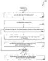
- FIG. 4Aa flowchart is provided of an antenna selection algorithm 400 in which the coding/modulation mode (e.g., data rate or throughput) is fixed or adapted on a long-term basis (e.g., adapted to the large-scale variations of the SNR).
- the task of the selection algorithmis to select which pair of antenna elements 316 should be used at the transmitter 302 and which pair of antenna elements 338 should be used at the receiver 330 with respect to each packet for the given mode.
- the selection processmay assume, for example, that the channel 318 is quasi-stationary (e.g., the channel 318 is constant over the duration of the packet being transmitted and changes independently between two contiguous packets). Even though the channel 318 may exhibit some frequency selectivity, the antenna selection may be common to the entire frequency bandwidth.
- CSIchannel state information
- operations to acquire CSIare carried out at the receiver 330 .
- a training sequence composed of known symbolsis sent from the transmitter 302 to the receiver 330 .
- the channel 318is estimated based on the received signal and the known sequence of symbols.
- the complete channel matrixshould be estimated over the whole frequency bandwidth (e.g., the estimation of the channel path gain from all antenna elements 316 of the transmitter 302 to all antenna elements 338 of the receiver across all tones).
- Channel estimation techniques based on training sequences applicable to MIMO systemsare described in, for example, J. J. Van de Beek et al., “On Channel Estimation in OFDM Systems”, IEEE 45 th Vehicular Technology Conference , vol. 2, 25-28 July 1995, pp. 815-819 and A. N. Mody and G. L. Stuber, “Synchronization for MIMO OFDM Systems”, IEEE Globecom 2001, vol. 1, pp. 509-513, which are hereby incorporated herein by reference in their entirety.
- mode informationis acquired through execution of a link adaptation algorithm (step 404 ).
- the mode changemay occur slowly.
- Thisenables a link adaptation algorithm to be employed to decide which of the possible mode candidates is best suited to be used in view of the long-term average SNR.
- Employment of a link adaptation algorithmmay ensure that, given a mode selection criterion (e.g., a maximum data rate and a minimum transmit power), the most efficient mode is always used in view of long-term varying channel/SNR conditions.
- a mode selection criterione.g., a maximum data rate and a minimum transmit power
- An exemplary link adaptation algorithm capable of being utilized within frequency-selective MIMO systemsis described, for example, in “Adaptive Modulation and MIMO Coding for Broadband Wireless Data Networks”, by S.
- the mode selectionmay generally be independent of the method of selecting transmitter/receiver antenna elements.
- the modemay be selected based exclusively upon long-term SNR statistics. Accordingly, it changes at a much slower rate than that at which the antennas are selected.
- the selection algorithmmay select a new subset of antennas with respect to each packet realization, while the mode changes as a function of long-term SNR variations.
- Steps 406 , 408 and 410are repeatedly executed in a loop until all possible combinations of subsets of transmit/receive antenna elements have been evaluated (step 411 ).
- the complete channel matrixcan be represented in the frequency domain at tone k by a 4 ⁇ 4 matrix denoted by H k .
- H kAfter selection of a subset of two antennas at each side, the sub-channel matrix is reduced in size to a 2 ⁇ 2 matrix denoted by ⁇ tilde over (H) ⁇ k .
- Each iteration in the loop comprised of steps 406 , 408 and 410effects processing of one antenna subsystem.
- the post-processing signal-to-interference-and-noise ratio (SINR)is then computed at each tone k and for each transmitted spatially-multiplexed signal (Step 408 ).
- the SINRcan most often be found by a closed-form solution dependent upon which signal processing technique is used at the transmitter 302 and/or receiver 330 (e.g., Maximum Ratio Combining (MRC), Minimum Mean Square Error (MMSE), eigen-beamforming, and Maximum Likelihood (ML)).
- MRCMaximum Ratio Combining
- MMSEMinimum Mean Square Error
- MLMaximum Likelihood
- the SINRmay be determined as follows:
- SINR K⁇ s 2 ⁇ 2 ⁇ C k - 1
- the SINR informationis converted into BER information in view of the current mode (see, e.g., step 404 ). Since the BER may be a complicated function of the channel 318 and of the coding/modulation and antenna combining techniques used, an approximation of the BER may be used. The approximation may also be a function of the channel 318 and of the applicable coding/modulation and antenna combining techniques.
- the function ⁇is approximated by some known function. Specifically, the output BER is approximated by the average of the bit error rate over the channel, for example:
- BER k iis the bit error rate given the SINR at tone k for spatially-multiplexed substream i.
- BER kcan also be the bit error rate given the signal-to-noise ratio at tone k.
- the averagemay also be taken in the time domain where BER k is the bit error rate given the SINR at channel time sample k.
- BER kmay be the bit error rate with respect to a given signal component (e.g., a signal tone or tap delay).
- BER kis also approximated by some simple closed-form function.
- mode 1 of 802.1-1ae.g., BPSK, R1/2
- the behavior of the average bit error rate BER with respect to the SINR or SNRin some examples, the BER normalization factor 1/N t may be omitted, since it does not affect the antenna selection
- the tan h functionmay not always adequately approximate the BER, particularly for different modulation techniques. Some of the following functions may generally afford better approximations when using particular techniques:
- the BER of an uncoded 16QAM modulation in AWGN channelmay be derived from the symbol error rate (SER) given, for example, in J. G. Proakis, Digital Communications, 3 rd Ed. McGraw-Hill Series, 1995 as
- the BER of an uncoded 64QAM modulation in AWGN channelmay be derived from the symbol error rate (SER) given, for example, in J. G. Proakis, Digital Communications, 3 rd Ed. McGraw-Hill Series, 1995 as
- steps 406 to 410are iteratively performed until all possible combinations of subsets of antennas are considered (step 411 ). At the conclusion of this iterative process, a set of N estimates of BER values (one for each spatially-multiplexed signal) for all
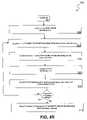
- FIG. 4Bis a flowchart of an antenna selection algorithm 500 in which the coding/modulation mode may be changed as frequently as once per packet realization in response to corresponding changes in the channel 318 .
- the coding/modulation modeis adapted at the same rate as antenna selection is effected.
- steps 501 and 502are similar to steps 401 and 402 , respectively.
- steps 504 through 510comprise a loop that is iteratively executed until all possible combinations of subsets of antennas have been evaluated. It follows that the number of iterations of this loop is equivalent to
- a link adaptation blockdetermines the most efficient mode for each spatially-multiplexed signal, given a mode selection criterion (e.g., a maximum data rate and a minimum transmit power) (step 508 ).
- a mode selection criterione.g., a maximum data rate and a minimum transmit power
- This stepis similar to step 404 , with the exception that the mode decision is made based upon instantaneous SNR (or SINR) statistics rather than upon long-term SNR (or SINR) statistics.
- step 510computes or determines the corresponding BER in the same manner as was described above with reference to step 410 .
- steps 504 through 510are performed until all possible combinations of subsets of antennas are considered (step 511 ). Once this has occurred, a set of N estimates of BER values (e.g., one for each spatially-multiplexed signal) for all
- the selection algorithm 500differs from the algorithm 400 in that the
- FIG. 5illustratively represents the packet error rate (PER) as function of SNR resulting from employment of an exemplary antenna selection technique within a SM-MIMO-OFDM system operative in a noise-limited environment.
- the results of FIG. 5may be applicable, for example, to a system using four transmit and receive antennas in the manner exemplified by FIG. 3 .
- the resultsreflect, as merely exemplary examples, a packet size of 1000 bytes and a fixed coding/modulation mode.
- the resultsalso reflect that two exemplary RF chains are incorporated within both the applicable transmitter and receiver.
- BPSK modulationuses BPSK modulation, a coding rate of 1/2 (e.g., mode 1 of 802.11a), a channel model characterized as “channel A” (e.g., 50 ns rms delay spread, 0.5 antenna correlation), and a fitting function of tan h.
- a coding rate of 1/2e.g., mode 1 of 802.11a
- channel model characterized as “channel A”e.g., 50 ns rms delay spread, 0.5 antenna correlation
- fitting function of tan huses BPSK modulation, a coding rate of 1/2 (e.g., mode 1 of 802.11a), a channel model characterized as “channel A” (e.g., 50 ns rms delay spread, 0.5 antenna correlation), and a fitting function of tan h.
- 2 ⁇ 2 2SM-MIMO MMSEThis system corresponds to a SM-MIMO-OFDM system using 2 transmit and 2 receive antennas together with 2 spatially-multiplexed (SM) signals. Since the number of antennas is equal to the number of SM signals, no antenna selection is applied. A baseband combining arrangement is used at the receiver to separate the two substreams, e.g., MMSE.
- SMspatially-multiplexed
- 4 ⁇ 4 2SM-MIMO sel mcap MMSEThis system corresponds to a SM-MIMO-OFDM system using 4 transmit and 4 receive antenna elements together with 2 spatially-multiplexed (SM) signals.
- a conventional selection methodis applied at both the transmitter and receiver to select a subset of 2 antenna elements among four, according to a maximum capacity criterion. After the selection at the receiver, MMSE is applied at baseband to separate the two substreams.
- 2 ⁇ 4 2SM-MIMO sel mber MMSE(bound): This system corresponds to a SM-MIMO-OFDM system using 2 transmit and 4 receive antenna elements together with 2 spatially-multiplexed (SM) signals.
- a selection methodis applied only at the receiver end to select a subset of 2 antenna elements among four, according to the minimum BER criterion. In this case, no fitting function is used to approximate the BER. Instead, the BER is assumed to be known perfectly. This case may not be readily implemented, but rather provides a bound on the performance which may be achieved through use of some embodiments according to some aspects of the present invention.
- This systemcorresponds to a SM-MIMO-OFDM system using 4 transmit and 4 receive antenna elements together with 2 spatially-multiplexed (SM) signals.
- a selection methodis applied at both transmit and receive sides to select a subset of 2 antenna elements among four, according to the minimum BER criterion. In this case, no fitting function is used to approximate the BER. Instead, the BER is assumed to be known perfectly. This case may not be readily implemented, but rather provides a bound on the performance which may be achieved through use of some embodiments according to some aspects of the present invention.
- This systemcorresponds to a SMMIMO-OFDM system using 4 transmit and 4 receive antenna elements together with 2 spatially-multiplexed (SM) signals.
- a selection method according to some embodiments according of the present inventionis applied at both transmit and receive sides to select a subset of 2 antenna elements among four, according to a minimum BER criterion.
- the fitting function to approximate the BERis tan h.
- the results illustratively represented by FIG. 5show that all systems using some type of antenna selection provide gains relative to systems with no selection, and that antenna selection based upon minimum BER provides significantly more gain than selection based upon the maximum capacity criterion.
- a PER level of 10e-2 and with antenna selection in accordance with the present invention being applied at both the transmitter and receivera 7.6 dB gain is achieved relative to a system with no selection and 4.2 dB gain is demonstrated relative to a system in which selection is based on maximum capacity.
- selectionis applied consistent with some embodiments according to some aspects of the present invention at only the receiver, the resulting performance is seen to be between that achieved when no selection is employed and that which occurs when selection is employed at both the transmitter and receiver.
- the performance of the system in accordance with some embodiments according to some aspects of the present inventionvery closely approaches a theoretical performance bound illustrated by FIG. 5 .
- FIG. 6illustrates a SC-MIMO-OFDM system 600 which utilizes precoding techniques in addition to an exemplary antenna selection method according to some embodiments of the present invention.
- precodingrefers to various baseband weighting and combining arrangements performed at a transmitter 602 .
- a single-stream of symbols 604is weighted by a set of complex coefficients 608 and combined to produce a set of N output signals where N refers to the number of RF chains 612 used within the transmitter 602 .
- These N output signalsare then passed through the N RF chains 612 in order to produce N RF signals.
- These N RF signalsare then coupled to a corresponding group of N of M transmit antenna elements 616 via a switch 620 and transmitted through a channel 624 .
- a set of N of M receive antenna elements 626is selected via a switch 630 to receive the incoming signals communicated through a channel 624 .
- the N RF receive signalsare then processed by N RF chains 634 and converted to the digital domain for baseband processing to recover the original transmitted signal.
- Some embodiments according to some aspects of the present inventionmay provide, for example, that the baseband weights 608 and antenna selection method are designed to collectively contribute to the minimization of the BER. Some embodiments according to some aspects of the present invention may provide, for example, that the baseband weights 608 may be chosen to maximize the output SNR (or SINR) or capacity, while the antenna selection is conducted so as to minimize the BER.
- the right and left singular vectors of the sub-channel matrix ⁇ tilde over (H) ⁇ k corresponding to the largest singular valuemay be used to select optimal subsets of transmit antenna elements 616 and receive antenna elements 626 as well as the appropriate transmit baseband weights 608 and receive baseband weights 640 .
- the exemplary embodiment illustrated in FIG. 6may be modified by replacing the baseband weights 608 within the transmitter 602 by a space-time coding block.
- an antenna selection methodmay be employed to select the subset of antennas in both the transmitter and receiver in accordance with some embodiments of the present invention.
- the space-time coding blockprocesses the input stream of symbols as described in, for example, “A simple transmit diversity technique for wireless communications”, by S. M. Alamouti, IEEE Journal on Selected Areas in Communications, vol. 16, issue 8, October 1998, pages 1451-1458, which is incorporated herein by reference in its entirety.
- the receiver 700integrates RAKE receiver functionality together with an exemplary antenna selection process.
- the receiver 700is equipped with only a single RF chain 708 disposed to be connected to only one of the two receive antenna elements 704 at any given time via a switch 712 .
- the choice of which of the two elements 704 to connect to the RF chain 708is made based upon the minimum BER criterion.
- Some embodiments according to some aspects of the present inventionmay provide that the received signal BER corresponding to each receive antenna element 704 is computed and the element 704 yielding the minimum value of BER is selected.
- the BERmay typically comprise a complicated function of the applicable channel and of the coding/modulation and antenna combining techniques used, the BER for a given channel and antenna combining technique is approximated such that it varies as a function of the coding/modulation method used.
- the RAKE receiverbehaves in the same way as if it were implemented in a single-input single-output (SISO) system (e.g., one antenna at each end of the link).
- SISOsingle-input single-output
- the output of each correlator 720e.g., a finger
- the received signal corresponding to the i th antenna element 704 at the input of the RAKE receivermay be expressed as:
- L iis the number of taps in the channel received at the i th antenna element 704
- h i,lis the complex channel gain at antenna i and tap l
- Pis the signal transmit power
- dis the data sequence comprised of symbols of period T
- ⁇ i,lis the path delay associated with tap l and antenna i
- ⁇ i,lis the phase shift corresponding to tap l and antenna i.
- Equation (3)assumes a single-user environment. However, the present invention need not be so limited and also contemplates being applied in the presence of multiple users.
- the received signalmay be represented as:
- d 0is the desired symbol to be demodulated
- n i,jis the AWGN noise component with zero-mean and with two-side spectral density N 0 /2.
- the final output of the RAKE receiver corresponding to the i th antenna element 704is:
- the RAKEperforms maximum ratio combining and the SNR at the RAKE output, corresponding the i th antenna element 704 is given by
- ⁇ i,jis the post-combining SNR on the j th path associated with the i th antenna element 704 .
- ⁇ i,jmay be expressed by:
- ⁇ i , j⁇ h i , j ⁇ 2 ⁇ P ⁇ 2 ⁇ ⁇
- ⁇ ⁇ ⁇ 2N 0 2 ⁇ 2 T ⁇ ⁇ is the noise power .
- the BER at the output of the RAKE receiver corresponding to the i th antenna element 704may be obtained from the knowledge of the probability density function (PDF) of ⁇ i .
- PDFprobability density function
- the BERis found by integrating the conditional error probability represented by Q( ⁇ square root over (2 ⁇ i ) ⁇ ) over the PDF of ⁇ i , for example:
- BER i⁇ 0 ⁇ ⁇ Q ⁇ ( 2 ⁇ ⁇ i ) ⁇ p ⁇ ⁇ ( ⁇ i ) ⁇ ⁇ d ⁇ i ( 9. )
- the antenna element 704 yielding the minimum BERis selected:
- n Rrepresents the total number of receiver antenna elements.
- the modeling function used in (9) to estimate the BERwill need to change.
- Some embodiments according to some aspects of the present inventionmay provide that any fitting function which accurately models BER behavior for a given system may be used by an exemplary antenna selection algorithm.
- the fitting functionwill generally be dependent upon parameters including, for example, one or more of the following: the channel, coding and modulation used, signal processing at transmit and/or receiver side, receiver SNR and other parameters.
- the exemplary embodiment illustrated in FIG. 7may be extended to a two-dimensional RAKE receiver in which processing is conducted in both the space and time domain.
- an exemplary antenna selection algorithmmay be incorporated to select a subset of N antennas (N>1), from a total of M antennas (M>N), which minimize the BER at the output of the 2D-RAKE.
Landscapes
- Engineering & Computer Science (AREA)
- Computer Networks & Wireless Communication (AREA)
- Signal Processing (AREA)
- Radio Transmission System (AREA)
- Mobile Radio Communication Systems (AREA)
Abstract
Description
possibilities in selecting 2 elements out of a total of 4. Since the antenna selection is applied at both the
possibilities in selecting n antenna element from M possible elements. When the selection occurs at both a transmitter and receiver, the total number of combinations for {tilde over (H)}kis equal to
This corresponds to the number of iterations of the loop comprised of
- Compute
- σ2and σs2stand for noise and signal power respectively and k=1, . . . , Nt(step408-1).
- Compute Ck=1/diag(Bk−1) this is a N×1 vector for each k=1, . . . , Nt(step408-2).
- Compute
- this is a N×1 vector for each k=1, . . . , Nt(step408-3).
where BERkiis the bit error rate given the SINR at tone k for spatially-multiplexed substream i. In another example, BERkcan also be the bit error rate given the signal-to-noise ratio at tone k. The average may also be taken in the time domain where BERkis the bit error rate given the SINR at channel time sample k. BERkmay be the bit error rate with respect to a given signal component (e.g., a signal tone or tap delay).
The BER at signal component k has been approximated by −tan h(SINRk).
The shape of the function erfc is reasonably approximated by the function (as compared to y=−tan h(x))
y=−[(1−e−2√{square root over (x)})+(1−e−1.8x)]
The shape of erfc(√{square root over (x/2)}) is better approximated by the function:
y=−[(1−e−1.3√{square root over (x)})+(1−e−x)]
than by y=−tan h(x).
An appropriate fitting function is y=−(1−e−0.2x).
An appropriate fitting function is y=−(1−e−0.35√{square root over (x)}).
possible antennas combinations is obtained. It then remains to select the subset of antennas that minimize the mean over the set of BERs, the maximum over the set of BERs or, the minimum of the set of BERs (step412).
(e.g., selection at one end of the link) or
(e.g., selection at both ends of the link). In this regard steps504 and506 are similar to
possible antennas combinations is obtained. The
possible antennas combinations do not necessarily use the same coding/modulation mode. The decision of which antennas subset to select therefore depends not only on a minimization of the BER but also on the mode (e.g., data rate or throughput). Several exemplary options are provided with regard to the final decision of selecting a subset of antenna elements pursuant to step512 of the selection algorithm500:
- 1) Group all combinations of subsets of antennas using the same mode into a common pool.
- 2) Choose the pool corresponding to the highest mode (yielding maximum data rate).
- 3) Within that pool, select the combination of subset of antennas that minimizes the BER in a manner substantially similar to that described with reference to
Step 412.
- Regardless of which mode is used by each combination, select the combination of antenna subsets that minimizes the BER in a manner substantially similar to that described with reference to
Step 412.
- Regardless of which mode is used by each combination, select the combination of antenna subsets that minimizes the BER in a manner substantially similar to that described with reference to
- 1) Group all combinations of subsets of antennas using the same mode into a common pool.
- 2) Choose the X pools corresponding to the X highest modes (yielding maximum data rate), where X is an integer equal to 1, or 2 or 3, etc.
- 3) Within these pools, select the combination of subset of antennas that minimizes the BER in a manner substantially similar to that described with reference to step412.
where Liis the number of taps in the channel received at the ithantenna element704, hi,lis the complex channel gain at antenna i and tap l, P is the signal transmit power, d is the data sequence comprised of symbols of period T, and p is the spreading sequence composed of chips of period Tc=T/G, where G is the spreading factor. In addition, τi,lis the path delay associated with tap l and antenna i, w0corresponds to the carrier frequency w0=2πf0, and θi,lis the phase shift corresponding to tap l and antenna i. The noise nimeasured at the ithantenna element704 is modeled as an AWGN process with two-side spectral density N0/2. For the sake of simplicity and clarity of expression, equation (3) assumes a single-user environment. However, the present invention need not be so limited and also contemplates being applied in the presence of multiple users.
where d0is the desired symbol to be demodulated, and ni,jis the AWGN noise component with zero-mean and with two-side spectral density N0/2. Again for purposes of simplicity and clarity of presentation, it was assumed in equation (4) that there is no interpath interference (IPI). However, the present invention also contemplates being used in the presence of IPI.
where J is the number of RAKE fingers and where the optimum combining weights are generally chosen so as to match the channel, for example:
wi,j=h*i,j (6.)
where γi,jis the post-combining SNR on the jthpath associated with the ithantenna element704. Based on (4), γi,jmay be expressed by:
where nRrepresents the total number of receiver antenna elements.
Claims (52)
Priority Applications (15)
| Application Number | Priority Date | Filing Date | Title |
|---|---|---|---|
| US10/979,992US7515939B2 (en) | 2003-10-01 | 2004-11-03 | System and method for channel-adaptive antenna selection |
| CN200480030570XACN1868147B (en) | 2003-11-12 | 2004-11-12 | System and method for channel-adaptive antenna selection |
| DE202004021937UDE202004021937U1 (en) | 2003-11-12 | 2004-11-12 | System for channel adaptive antenna selection |
| EP04810900AEP1685662A1 (en) | 2003-11-12 | 2004-11-12 | System and method for channel-adaptive antenna selection |
| PCT/US2004/037916WO2005048486A1 (en) | 2003-11-12 | 2004-11-12 | System and method for channel-adaptive antenna selection |
| DE202004021935UDE202004021935U1 (en) | 2003-11-12 | 2004-11-12 | System for channel adaptive antenna selection |
| US11/009,503US7391832B2 (en) | 2003-03-17 | 2004-12-10 | System and method for channel bonding in multiple antenna communication systems |
| EP04818011.1AEP1733485B1 (en) | 2003-12-11 | 2004-12-10 | Spatial multiplexing in mimo systems |
| PCT/US2004/041809WO2005062498A1 (en) | 2003-12-11 | 2004-12-10 | Spatial multiplexing in mimo systems |
| CN2004800368342ACN1918814B (en) | 2003-12-11 | 2004-12-10 | Spatial multiplexing in mimo systems |
| US12/119,231US8185075B2 (en) | 2003-03-17 | 2008-05-12 | System and method for channel bonding in multiple antenna communication systems |
| US12/418,091US7840235B2 (en) | 2003-10-01 | 2009-04-03 | System and method for channel-adaptive antenna selection |
| US12/953,005US8000746B2 (en) | 2003-10-01 | 2010-11-23 | System and method for channel-adaptive antenna selection |
| US13/209,968US8401591B2 (en) | 2003-10-01 | 2011-08-15 | System and method for channel-adaptive antenna selection |
| US13/753,097US8706166B2 (en) | 2003-10-01 | 2013-01-29 | System and method for channel-adaptive antenna selection |
Applications Claiming Priority (4)
| Application Number | Priority Date | Filing Date | Title |
|---|---|---|---|
| US50784303P | 2003-10-01 | 2003-10-01 | |
| US51939803P | 2003-11-12 | 2003-11-12 | |
| US10/957,398US7483718B2 (en) | 2003-10-01 | 2004-10-01 | System and method for antenna selection |
| US10/979,992US7515939B2 (en) | 2003-10-01 | 2004-11-03 | System and method for channel-adaptive antenna selection |
Related Parent Applications (2)
| Application Number | Title | Priority Date | Filing Date |
|---|---|---|---|
| US10/957,398Continuation-In-PartUS7483718B2 (en) | 2003-03-17 | 2004-10-01 | System and method for antenna selection |
| US10/979,992Continuation-In-PartUS7515939B2 (en) | 2003-03-17 | 2004-11-03 | System and method for channel-adaptive antenna selection |
Related Child Applications (4)
| Application Number | Title | Priority Date | Filing Date |
|---|---|---|---|
| US10/957,398Continuation-In-PartUS7483718B2 (en) | 2003-03-17 | 2004-10-01 | System and method for antenna selection |
| US10/979,992Continuation-In-PartUS7515939B2 (en) | 2003-03-17 | 2004-11-03 | System and method for channel-adaptive antenna selection |
| US11/009,503Continuation-In-PartUS7391832B2 (en) | 2003-03-17 | 2004-12-10 | System and method for channel bonding in multiple antenna communication systems |
| US12/418,091ContinuationUS7840235B2 (en) | 2003-10-01 | 2009-04-03 | System and method for channel-adaptive antenna selection |
Publications (2)
| Publication Number | Publication Date |
|---|---|
| US20050090205A1 US20050090205A1 (en) | 2005-04-28 |
| US7515939B2true US7515939B2 (en) | 2009-04-07 |
Family
ID=34595942
Family Applications (5)
| Application Number | Title | Priority Date | Filing Date |
|---|---|---|---|
| US10/979,992Expired - Fee RelatedUS7515939B2 (en) | 2003-03-17 | 2004-11-03 | System and method for channel-adaptive antenna selection |
| US12/418,091Expired - Fee RelatedUS7840235B2 (en) | 2003-10-01 | 2009-04-03 | System and method for channel-adaptive antenna selection |
| US12/953,005Expired - Fee RelatedUS8000746B2 (en) | 2003-10-01 | 2010-11-23 | System and method for channel-adaptive antenna selection |
| US13/209,968Expired - Fee RelatedUS8401591B2 (en) | 2003-10-01 | 2011-08-15 | System and method for channel-adaptive antenna selection |
| US13/753,097Expired - Fee RelatedUS8706166B2 (en) | 2003-10-01 | 2013-01-29 | System and method for channel-adaptive antenna selection |
Family Applications After (4)
| Application Number | Title | Priority Date | Filing Date |
|---|---|---|---|
| US12/418,091Expired - Fee RelatedUS7840235B2 (en) | 2003-10-01 | 2009-04-03 | System and method for channel-adaptive antenna selection |
| US12/953,005Expired - Fee RelatedUS8000746B2 (en) | 2003-10-01 | 2010-11-23 | System and method for channel-adaptive antenna selection |
| US13/209,968Expired - Fee RelatedUS8401591B2 (en) | 2003-10-01 | 2011-08-15 | System and method for channel-adaptive antenna selection |
| US13/753,097Expired - Fee RelatedUS8706166B2 (en) | 2003-10-01 | 2013-01-29 | System and method for channel-adaptive antenna selection |
Country Status (3)
| Country | Link |
|---|---|
| US (5) | US7515939B2 (en) |
| EP (1) | EP1685662A1 (en) |
| WO (1) | WO2005048486A1 (en) |
Cited By (15)
| Publication number | Priority date | Publication date | Assignee | Title |
|---|---|---|---|---|
| US20080081570A1 (en)* | 2006-09-29 | 2008-04-03 | Wun Cheol Jeong | Apparatus and method for selecting antennas and nodes mimo communication system |
| US20080085738A1 (en)* | 2006-10-10 | 2008-04-10 | Guoqing Li | Adaptive multiple-antenna systems with omni-directional and sector-directional antenna modes |
| US20080117865A1 (en)* | 2006-11-17 | 2008-05-22 | Li Guoqing C | Communication in a wireless network using multiple antennae |
| US20080139156A1 (en)* | 2006-12-06 | 2008-06-12 | Broadcom Corporation, A California Corporation | RF receiver with fast baseband switching |
| US20080139231A1 (en)* | 2006-12-07 | 2008-06-12 | Rehan Jalil | method and system for spectrum reuse in the downlink in a wireless communication network |
| US20080139211A1 (en)* | 2006-12-07 | 2008-06-12 | Rehan Jalil | method and system for spectrum reuse in the uplink in a wireless communication network |
| US20080261551A1 (en)* | 2003-03-17 | 2008-10-23 | Broadcom Corporation | System and method for channel bonding in multiple antenna communication systems |
| US20090191832A1 (en)* | 2003-10-01 | 2009-07-30 | Broadcom Corporation | System and method for antenna selection |
| US20090201205A1 (en)* | 2003-10-01 | 2009-08-13 | Broadcom Corporation | System and method for channel-adaptive antenna selection |
| US20100091891A1 (en)* | 2008-10-10 | 2010-04-15 | Wipro Limited | Link quality metric based antenna selection for transceivers |
| US20100135238A1 (en)* | 2005-10-26 | 2010-06-03 | Sadri Ali S | Systems for communicating using multiple frequency bands in a wireless network |
| US20110059699A1 (en)* | 2005-03-07 | 2011-03-10 | Qualcomm Incorporated | Rate selection for a quasi-orthogonal communication system |
| US20110267955A1 (en)* | 2010-05-03 | 2011-11-03 | Nokia Corporation | Monitoring pattern separation between component carriers based on user equipment RF layout |
| US20160262181A1 (en)* | 2013-10-21 | 2016-09-08 | Samsung Electronics Co., Ltd. | Apparatus and method for performing user terminal selection operation and beam forming operation in wireless communication system supporting mimo technology |
| US10193733B2 (en) | 2005-10-26 | 2019-01-29 | Intel Corporation | Wireless communication system to communicate using different beamwidths |
Families Citing this family (72)
| Publication number | Priority date | Publication date | Assignee | Title |
|---|---|---|---|---|
| US7391832B2 (en)* | 2003-03-17 | 2008-06-24 | Broadcom Corporation | System and method for channel bonding in multiple antenna communication systems |
| JP2004325239A (en)* | 2003-04-24 | 2004-11-18 | Sharp Corp | Antenna gain identification device and wireless communication device |
| US8306574B2 (en) | 2003-10-29 | 2012-11-06 | Robert Warner | Method and system for an adaptive wireless communication system optimized for economic benefit |
| US7123580B2 (en)* | 2004-01-16 | 2006-10-17 | Nokia Corporation | Multiple user adaptive modulation scheme for MC-CDMA |
| US7349458B2 (en)* | 2004-05-17 | 2008-03-25 | Mitsubishi Electric Research Laboratories, Inc. | Linear receivers for time-hopping impulse radio systems |
| DE102004026071A1 (en)* | 2004-05-25 | 2005-12-22 | Micronas Gmbh | Method and device for processing received data of a radio interface |
| US7649959B2 (en)* | 2004-09-27 | 2010-01-19 | Nokia Corporation | Transmission format indication and feedback in multi-carrier wireless communication systems |
| US7796702B2 (en)* | 2005-07-27 | 2010-09-14 | Interdigital Technology Corporation | Coded antenna switching for wireless communications and associated methods |
| US20090129501A1 (en)* | 2005-08-19 | 2009-05-21 | Mehta Neelesh B | Optimal signaling and selection verification for transmit antenna selection with erroneous feedback |
| US7907971B2 (en)* | 2005-08-22 | 2011-03-15 | Airgain, Inc. | Optimized directional antenna system |
| CN100399720C (en)* | 2005-08-26 | 2008-07-02 | 电子科技大学 | Multi-antenna communication method and communication system adaptively adjusted according to channel spatial correlation |
| JP2007067707A (en)* | 2005-08-30 | 2007-03-15 | Toshiba Corp | Receiver |
| US9356674B2 (en)* | 2005-09-21 | 2016-05-31 | Broadcom Corporation | Method and system for using non-uniform channel quantization for a feedback-based communication system |
| WO2007040515A2 (en)* | 2005-09-30 | 2007-04-12 | Mitsubishi Electric Research Laboratories | Training signals for selecting antennas and beams in mimo wireless lans |
| US7801253B1 (en)* | 2005-10-19 | 2010-09-21 | Marvell International Ltd. | Nonlinear post-processors for channels with signal-dependent noise |
| US7657244B2 (en)* | 2005-10-27 | 2010-02-02 | Samsung Electronics Co., Ltd. | Methods of antenna selection for downlink MIMO-OFDM transmission over spatial correlated channels |
| EP1964211A4 (en)* | 2005-12-12 | 2011-04-27 | Wi Lan Inc | Self-installable switchable antenna |
| CN101005303B (en)* | 2006-01-18 | 2010-08-18 | 中兴通讯股份有限公司 | Selective and adaptive modulation method for transmitting antenna in multiple input and multiple output orthogonal frequency division multiplex system |
| JP4594881B2 (en)* | 2006-03-02 | 2010-12-08 | 富士通株式会社 | Multi-input multi-output communication device |
| US7627347B2 (en) | 2006-03-17 | 2009-12-01 | Nokia Corporation | Data transmission parameter optimization in MIMO communications system |
| US8155712B2 (en) | 2006-03-23 | 2012-04-10 | Sibeam, Inc. | Low power very high-data rate device |
| JP4775288B2 (en) | 2006-04-27 | 2011-09-21 | ソニー株式会社 | Wireless communication system, wireless communication apparatus, and wireless communication method |
| JP4924106B2 (en) | 2006-04-27 | 2012-04-25 | ソニー株式会社 | Wireless communication system, wireless communication apparatus, and wireless communication method |
| JP4356756B2 (en) | 2006-04-27 | 2009-11-04 | ソニー株式会社 | Wireless communication system, wireless communication apparatus, and wireless communication method |
| JP4924107B2 (en) | 2006-04-27 | 2012-04-25 | ソニー株式会社 | Wireless communication system, wireless communication apparatus, and wireless communication method |
| CN101064542B (en)* | 2006-04-30 | 2010-12-08 | 中兴通讯股份有限公司 | MIMO OFDML aunching aerial selection and self-adapting modulation approach of system |
| CN100571242C (en)* | 2006-05-12 | 2009-12-16 | 中兴通讯股份有限公司 | Realize the method for Adaptive Modulation in a kind of ofdm system |
| US20070268988A1 (en)* | 2006-05-19 | 2007-11-22 | Navini Networks, Inc. | Method and system for optimal receive diversity combining |
| US7801204B2 (en)* | 2006-05-26 | 2010-09-21 | Texas Instruments Incorporated | Estimation of BER performance |
| JP2008017096A (en)* | 2006-07-05 | 2008-01-24 | Fujitsu Ltd | COMMUNICATION SYSTEM FOR TRANSMITTING / RECEIVING BY MULTIPLE ANTENNA |
| KR101099881B1 (en)* | 2006-09-06 | 2011-12-28 | 고려대학교 산학협력단 | Method and device for antenna selection in orthogonal spatial multiplexing system |
| US20080064356A1 (en)* | 2006-09-07 | 2008-03-13 | Telefonaktiebolaget Lm Ericsson (Publ) | Method of receiving wideband signal |
| US20080146163A1 (en)* | 2006-12-14 | 2008-06-19 | Motorola, Inc. | Diversity control of multi-mode communication devices |
| US20080151871A1 (en)* | 2006-12-22 | 2008-06-26 | Nokia Corporation | Power-Efficient Multi-Branch Reception |
| US8761079B2 (en)* | 2007-01-30 | 2014-06-24 | Motorola Mobility Llc | Method and apparatus for selecting appropriate coding scheme and transmission rate for transmitting a frame across a communication network |
| US8824420B2 (en)* | 2007-03-22 | 2014-09-02 | Mitsubishi Electric Research Laboratories, Inc. | Method and system for generating antenna selection signals in OFDM tranceivers with fewer RF chains than antennas in MIMO wireless networks |
| US20080248802A1 (en)* | 2007-04-09 | 2008-10-09 | Tzero Technologies, Inc. | Antenna pattern selection within a wireless network |
| KR101414611B1 (en)* | 2007-04-19 | 2014-07-07 | 엘지전자 주식회사 | Method for transmitting signals in a multi-antenna system |
| DE112008001354B4 (en)* | 2007-05-29 | 2016-06-16 | Mitsubishi Electric Corp. | Digital broadcast receiving device |
| US20090124290A1 (en)* | 2007-11-09 | 2009-05-14 | Zhifeng Tao | Antenna Selection for SDMA Transmissions in OFDMA Networks |
| ATE546888T1 (en)* | 2007-12-19 | 2012-03-15 | Telecom Italia Spa | METHOD AND SYSTEMS FOR RECEIVING MULTIPLE INFORMATION FLOWS IN A MIMO SYSTEM |
| WO2009098532A1 (en)* | 2008-02-07 | 2009-08-13 | Nokia Corporation | Apparatus, methods, and computer program products providing improved spatial multiplexing for mimo communication |
| US8494466B2 (en)* | 2008-03-26 | 2013-07-23 | Broadcom Corporation | Selecting receiver chains of a mobile unit for receiving wireless signals |
| WO2010088721A1 (en)* | 2009-02-04 | 2010-08-12 | Commonwealth Scientific And Industrial Research Organisation | Method and apparatus for antenna and transmission mode switching |
| GB2475307B (en)* | 2009-11-13 | 2012-05-16 | Toshiba Res Europ Ltd | Wireless communications apparatus and method |
| US9140779B2 (en)* | 2010-03-08 | 2015-09-22 | Nederlandse Organisatie Voor Toegepast-Natuurwetenschappelijk Onderzoek Tno | Method of compensating sub-array or element failure in a phased array radar system, a phased array radar system and a computer program product |
| TWI426791B (en)* | 2010-06-09 | 2014-02-11 | Univ Ishou | Interrupt capacity calculation device and method |
| US8532214B2 (en)* | 2010-07-01 | 2013-09-10 | Telefonaktiebolaget L M Ericsson (Publ) | MIMO channel state information estimation with coupled iterative two-stage ranking |
| US9166667B2 (en) | 2011-10-12 | 2015-10-20 | Honeywell International Inc. | Antenna selection diversity scheme for zigbee or other wireless devices and related apparatus and method |
| US9436250B1 (en)* | 2011-12-19 | 2016-09-06 | Altera Corporation | Apparatus for improving power consumption of communication circuitry and associated methods |
| CN102571182B (en)* | 2012-01-20 | 2014-08-13 | 杭州华三通信技术有限公司 | Method for selecting receiving antenna in wireless local area network and device thereof |
| US9125138B2 (en)* | 2012-02-29 | 2015-09-01 | Apple Inc. | System and method for optimizing video conferencing in a wireless device |
| CN104380618B (en)* | 2012-03-23 | 2018-07-20 | 阿尔卡特朗讯 | Method, equipment and computer program for testing transceiver devices |
| GB2502108B (en)* | 2012-05-16 | 2014-10-15 | Canon Kk | Reception quality assessment |
| CN103595520B (en)* | 2012-08-16 | 2017-08-04 | 华为技术有限公司 | Communication device and its space division duplex method |
| US20140179235A1 (en)* | 2012-12-20 | 2014-06-26 | Mediatek Inc. | Method for reducing power consumption and communications apparatus utilizing the same |
| EP2950574A4 (en)* | 2013-01-25 | 2016-01-20 | Ntt Docomo Inc | Mobile communication terminal |
| CN104158579A (en)* | 2013-05-14 | 2014-11-19 | 华为技术有限公司 | Method and device for antenna selection |
| EP3058688A4 (en) | 2013-10-16 | 2017-06-28 | Empire Technology Development LLC | Signal sequence estimation |
| EP2869476A1 (en)* | 2013-10-29 | 2015-05-06 | Alcatel Lucent | Transmitter Method For Multiple Antenna Systems, Transmitter Apparatus And Network Node Thereof |
| US10247820B2 (en) | 2015-01-07 | 2019-04-02 | GM Global Technology Operations LLC | Spatial cognitive radar |
| CN104639221B (en)* | 2015-01-19 | 2018-01-09 | 电子科技大学 | A kind of joint antenna system of selection for spatial phase modulation |
| CN106992837B (en)* | 2016-01-20 | 2020-06-16 | 华为技术有限公司 | Multi-antenna data transmission method, network equipment, terminal equipment and system |
| KR102429965B1 (en)* | 2016-02-19 | 2022-08-08 | 삼성전자주식회사 | Method and Apparatus for Selecting Rx Antenna Set |
| US20170293024A1 (en)* | 2016-04-07 | 2017-10-12 | GM Global Technology Operations LLC | Cognitive transmission switching |
| CN107734586B (en)* | 2017-09-28 | 2021-02-23 | Oppo广东移动通信有限公司 | Antenna switching method and mobile terminal |
| WO2019168453A1 (en)* | 2018-02-28 | 2019-09-06 | Telefonaktiebolaget Lm Ericsson (Publ) | Method and apparatus for combining signals from a plurality of antennas |
| CN109324309B (en)* | 2018-09-10 | 2020-12-04 | 中国航天科工集团八五一一研究所 | Rotary single-antenna angle measuring device and measuring method thereof |
| CN113169774B (en)* | 2018-12-03 | 2022-10-28 | 华为技术有限公司 | Antenna selection method and device |
| CN115085776B (en)* | 2021-03-16 | 2024-08-20 | 华为技术有限公司 | Antenna selection method and related product |
| CN116388816A (en)* | 2022-01-03 | 2023-07-04 | 联发科技股份有限公司 | Antenna Selection Method for User Equipment |
| CN115764255B (en)* | 2022-11-18 | 2023-06-23 | 上海海积信息科技股份有限公司 | Anti-interference antenna |
Citations (20)
| Publication number | Priority date | Publication date | Assignee | Title |
|---|---|---|---|---|
| US6327314B1 (en)* | 1998-04-01 | 2001-12-04 | At&T Corp. | Method and apparatus for channel estimation for multicarrier systems |
| WO2002003557A1 (en) | 2000-06-30 | 2002-01-10 | Iospan Wireless, Inc. | Method and system for mode adaptation in wireless communication |
| US20020051435A1 (en) | 2000-10-27 | 2002-05-02 | L-3 Communications Corporation | Two-dimensional channel bonding in a hybrid CDMA/FDMA fixed wireless access system to provide finely variable rate channels |
| US20020102950A1 (en) | 2001-01-26 | 2002-08-01 | Gore Dhananjay A. | Method and apparatus for selection and use of optimal antennas in wireless systems |
| US20020197998A1 (en) | 2001-06-22 | 2002-12-26 | Schmidt Dominik J. | Cellular channel bonding for improved data transmission |
| US20030083016A1 (en) | 2001-10-19 | 2003-05-01 | Koninklijke Philips Electronics N.V. | Method of operating a wireless communication system |
| US6654429B1 (en)* | 1998-12-31 | 2003-11-25 | At&T Corp. | Pilot-aided channel estimation for OFDM in wireless systems |
| US6731685B1 (en)* | 2000-09-20 | 2004-05-04 | General Instrument Corporation | Method and apparatus for determining a bit rate need parameter in a statistical multiplexer |
| US20050031047A1 (en)* | 2003-08-08 | 2005-02-10 | Maltsev Alexander A. | Adaptive multicarrier wireless communication system, apparatus and associated methods |
| US20050047517A1 (en)* | 2003-09-03 | 2005-03-03 | Georgios Giannakis B. | Adaptive modulation for multi-antenna transmissions with partial channel knowledge |
| US20050074080A1 (en) | 2003-05-01 | 2005-04-07 | Severine Catreux | Weight generation method for multi-antenna communication systems utilizing RF-based and baseband signal weighting and combining |
| US20050075081A1 (en)* | 2003-10-01 | 2005-04-07 | Severine Catreux-Erceg | System and method for antenna selection |
| US20050090205A1 (en) | 2003-10-01 | 2005-04-28 | Severine Catreux-Erceg | System and method for channel-adaptive antenna selection |
| US20050141630A1 (en) | 2003-07-09 | 2005-06-30 | Severine Catreux | Weight generation method for multi-antenna communication systems utilizing RF-based and baseband signal weighting and combining based upon minimum bit error rate |
| US20050238108A1 (en)* | 2004-04-07 | 2005-10-27 | Samsung Electronics Co., Ltd. | Apparatus and method for switching between an AMC mode and a diversity mode in a broadband wireless communication system |
| US20060176974A1 (en)* | 2002-02-26 | 2006-08-10 | Martin Smith | Radio communications device with adaptive combination |
| US7130354B1 (en)* | 2002-05-02 | 2006-10-31 | 3Com Corporation | Method and apparatus for improving error control properties for encoding and decoding data |
| US7283499B2 (en)* | 2004-10-15 | 2007-10-16 | Nokia Corporation | Simplified practical rank and mechanism, and associated method, to adapt MIMO modulation in a multi-carrier system with feedback |
| US7313737B2 (en)* | 2003-03-19 | 2007-12-25 | Nokia Corporation | Adaptive link adaptation |
| US7391832B2 (en)* | 2003-03-17 | 2008-06-24 | Broadcom Corporation | System and method for channel bonding in multiple antenna communication systems |
Family Cites Families (19)
| Publication number | Priority date | Publication date | Assignee | Title |
|---|---|---|---|---|
| US5579341A (en)* | 1994-12-29 | 1996-11-26 | Motorola, Inc. | Multi-channel digital transceiver and method |
| US6009307A (en)* | 1997-05-13 | 1999-12-28 | Qualcomm Incorporated | Multiple antenna detecting and selecting |
| US5999561A (en)* | 1997-05-20 | 1999-12-07 | Sanconix, Inc. | Direct sequence spread spectrum method, computer-based product, apparatus and system tolerant to frequency reference offset |
| JP4181259B2 (en) | 1998-12-14 | 2008-11-12 | 松下電器産業株式会社 | Receiving apparatus and receiving method |
| JP2000295151A (en)* | 1999-04-05 | 2000-10-20 | Matsushita Electric Ind Co Ltd | Diversity receiver |
| US6975603B1 (en)* | 1999-08-20 | 2005-12-13 | Siemens Communications Inc. | System and method for minimizing the loss of information in cordless communications |
| US6952454B1 (en)* | 2000-03-22 | 2005-10-04 | Qualcomm, Incorporated | Multiplexing of real time services and non-real time services for OFDM systems |
| US7155192B2 (en)* | 2001-09-25 | 2006-12-26 | At&T Corp. | Multi-antenna/multi-receiver array diversity system |
| US20030162519A1 (en) | 2002-02-26 | 2003-08-28 | Martin Smith | Radio communications device |
| US7315573B2 (en)* | 2002-02-28 | 2008-01-01 | Texas Instruments Incorporated | Channel monitoring for improved parameter selection in a communication system |
| US6907272B2 (en)* | 2002-07-30 | 2005-06-14 | UNIVERSITé LAVAL | Array receiver with subarray selection |
| US7542446B2 (en) | 2002-07-31 | 2009-06-02 | Mitsubishi Electric Research Laboratories, Inc. | Space time transmit diversity with subgroup rate control and subgroup antenna selection in multi-input multi-output communications systems |
| US7623836B1 (en)* | 2003-06-19 | 2009-11-24 | Intel Corporation | Antenna selection for multicarrier communications |
| WO2005034406A2 (en)* | 2003-09-25 | 2005-04-14 | Interdigital Technology Corporation | Method and system for enhancing reception of wireless communication signals |
| US20060264184A1 (en)* | 2005-02-17 | 2006-11-23 | Interdigital Technology Corporation | Method and apparatus for selecting a beam combination of multiple-input multiple-output antennas |
| US7697913B2 (en)* | 2005-12-19 | 2010-04-13 | Delphi Technologies, Inc. | Dual tuner diversity for background processing and to reduce multipath distortion |
| US8116259B2 (en)* | 2006-09-29 | 2012-02-14 | Broadcom Corporation | Method and system for diversity processing based on antenna switching |
| US9225397B2 (en)* | 2007-07-10 | 2015-12-29 | Texas Instruments Incorporated | Efficient rank and precoding matrix feedback for MIMO systems |
| JP5025356B2 (en)* | 2007-07-10 | 2012-09-12 | キヤノン株式会社 | COMMUNICATION SYSTEM, INFORMATION PROCESSING DEVICE, AND COMMUNICATION CONTROL METHOD |
- 2004
- 2004-11-03USUS10/979,992patent/US7515939B2/ennot_activeExpired - Fee Related
- 2004-11-12EPEP04810900Apatent/EP1685662A1/ennot_activeWithdrawn
- 2004-11-12WOPCT/US2004/037916patent/WO2005048486A1/enactiveApplication Filing
- 2009
- 2009-04-03USUS12/418,091patent/US7840235B2/ennot_activeExpired - Fee Related
- 2010
- 2010-11-23USUS12/953,005patent/US8000746B2/ennot_activeExpired - Fee Related
- 2011
- 2011-08-15USUS13/209,968patent/US8401591B2/ennot_activeExpired - Fee Related
- 2013
- 2013-01-29USUS13/753,097patent/US8706166B2/ennot_activeExpired - Fee Related
Patent Citations (20)
| Publication number | Priority date | Publication date | Assignee | Title |
|---|---|---|---|---|
| US6327314B1 (en)* | 1998-04-01 | 2001-12-04 | At&T Corp. | Method and apparatus for channel estimation for multicarrier systems |
| US6654429B1 (en)* | 1998-12-31 | 2003-11-25 | At&T Corp. | Pilot-aided channel estimation for OFDM in wireless systems |
| WO2002003557A1 (en) | 2000-06-30 | 2002-01-10 | Iospan Wireless, Inc. | Method and system for mode adaptation in wireless communication |
| US6731685B1 (en)* | 2000-09-20 | 2004-05-04 | General Instrument Corporation | Method and apparatus for determining a bit rate need parameter in a statistical multiplexer |
| US20020051435A1 (en) | 2000-10-27 | 2002-05-02 | L-3 Communications Corporation | Two-dimensional channel bonding in a hybrid CDMA/FDMA fixed wireless access system to provide finely variable rate channels |
| US20020102950A1 (en) | 2001-01-26 | 2002-08-01 | Gore Dhananjay A. | Method and apparatus for selection and use of optimal antennas in wireless systems |
| US20020197998A1 (en) | 2001-06-22 | 2002-12-26 | Schmidt Dominik J. | Cellular channel bonding for improved data transmission |
| US20030083016A1 (en) | 2001-10-19 | 2003-05-01 | Koninklijke Philips Electronics N.V. | Method of operating a wireless communication system |
| US20060176974A1 (en)* | 2002-02-26 | 2006-08-10 | Martin Smith | Radio communications device with adaptive combination |
| US7130354B1 (en)* | 2002-05-02 | 2006-10-31 | 3Com Corporation | Method and apparatus for improving error control properties for encoding and decoding data |
| US7391832B2 (en)* | 2003-03-17 | 2008-06-24 | Broadcom Corporation | System and method for channel bonding in multiple antenna communication systems |
| US7313737B2 (en)* | 2003-03-19 | 2007-12-25 | Nokia Corporation | Adaptive link adaptation |
| US20050074080A1 (en) | 2003-05-01 | 2005-04-07 | Severine Catreux | Weight generation method for multi-antenna communication systems utilizing RF-based and baseband signal weighting and combining |
| US20050141630A1 (en) | 2003-07-09 | 2005-06-30 | Severine Catreux | Weight generation method for multi-antenna communication systems utilizing RF-based and baseband signal weighting and combining based upon minimum bit error rate |
| US20050031047A1 (en)* | 2003-08-08 | 2005-02-10 | Maltsev Alexander A. | Adaptive multicarrier wireless communication system, apparatus and associated methods |
| US20050047517A1 (en)* | 2003-09-03 | 2005-03-03 | Georgios Giannakis B. | Adaptive modulation for multi-antenna transmissions with partial channel knowledge |
| US20050075081A1 (en)* | 2003-10-01 | 2005-04-07 | Severine Catreux-Erceg | System and method for antenna selection |
| US20050090205A1 (en) | 2003-10-01 | 2005-04-28 | Severine Catreux-Erceg | System and method for channel-adaptive antenna selection |
| US20050238108A1 (en)* | 2004-04-07 | 2005-10-27 | Samsung Electronics Co., Ltd. | Apparatus and method for switching between an AMC mode and a diversity mode in a broadband wireless communication system |
| US7283499B2 (en)* | 2004-10-15 | 2007-10-16 | Nokia Corporation | Simplified practical rank and mechanism, and associated method, to adapt MIMO modulation in a multi-carrier system with feedback |
Non-Patent Citations (27)
| Title |
|---|
| A. Gorokhov et al.; "Performance Bounds for Antenna Selection in MIMO Systems;" ICC 2003; 2003 IEEE International Conference on Communications; Anchorage, Alaska; May 2003; IEEE International Conference on Communications, New York, NY; IEEE, USA; vol. 1 of 5; May 2003; pp. 3021-3025; XP010643001; ISBN: 0-7803-7802-4. |
| Anders Furuskär et al., "EDGE: Enhanced Data Rates for GSM and TDMA/136 Evolution," IEEE Personal Communications Magazine, vol. 6, Issue 3, Jun. 1999, pp. 56-66. |
| Andreas F. Molisch, et al., "Capacity of MIMO Systems with Antenna Selection," Proceedings of IEEE ICC, Helsinki, Finland, Jun. 1001, vol. 2, pp. 570-574. |
| Apurva N. Moday, et al., "Synchornization for MIMO of OFDM Systems," IEEE Globecom 2001, vol. 1, pp. 509-513. |
| Chen-Nee Chuah, et al., "Capacity of Multi-antenna Array Systems in Indoor Wireless Environment," Proceedings of Globecom'98 Sydney, Australia, IEEE 1998, pp. 1894-1899. |
| D. Gore et al.; "Statistical MIMO Antenna Sub-set Selection with Space-time Coding;" ICC 2002; 2002 IEEE International Conference on Communications, Conference Proceedings, New York, NY; Apr.-May 2002; IEEE International Conference on Communications, New York, NY; IEEE, USA; vol. 1 of 5; Apr. 2002; pp. 641-645; XP010589572; ISBN: 0-7803-7400-2. |
| D.A. Gore et al.; "MIMO Antenna Subset Selection with Space-time Coding;" IEEE Transactions on Signal Processing, IEEE, Inc., New York, USA; vol. 50, No. 10, Oct. 2002; pp. 2580-2588; XP001200163; ISSN: 1053-587X. |
| Da-Shan Shiu, et al., "Fading Correlation and Its Effect on the Capacity of Multielement Antenna Systems," IEEE Transactions on Communications, vol. 48, No. 3, pp. 502-513, Mar. 2000. |
| G.J. Foschini, et al., "On Limits of Wireless Communications in a Fading Environment when Using Multiple Antennas," Kluwer Academic Publishers, vol. 6, No. 3, Mar. 1998, pp. 311-335. |
| G.J. Foschini, et al., "Simplified Processing for High Spectral Efficiency Wireless Communication Employing Multi-element Arrays," IEEE Journal on Selected Areas in Communications, vol. 17, Issue 11, Nov. 1999, pp. 1841-1852. |
| H-S Kim et al.; "Optimal Antenna Selection Scheme with Transmit Adaptive Array for Wideband CDMA Systems;" IEICE Transactions on Fundamentals of Electronics, Communications and Computer Sciences, Institute of Electronics Information and Comm. Eng., Tokyo, Japan; vol. E86A, No. 6; Jun. 2003; pp. 1414-1420, XP001171080; ISSN: 0916-8508. |
| IEEE 802.11a standard, 1999. |
| IEEE 802.11a standard. |
| IEEE 802.11g standard, Jun. 23, 2003. |
| IEEE 802.11g standard. |
| Jack H. Winters, "Optimum Combining for Indoor Radio Systems with Multiple Users," IEEE Transactions on Communications, vol. COM-35, No. 11, Nov. 1987, pp. 1222-1230. |
| Jack H. Winters, et al., "The Impact of Antenna Diversity on the Capacity of Wireless Communication Systems," IEEE Transactions on Communications, vol. 42, No. 2/3/4, Feb.,Mar., Apr. 1994, pp. 1740-1751. |
| Jan-Jaap Van De Beek, et al., "On Channel Estimation in OFDM Systems," IEEE 45th Vehicular Technology conference, vol. 2, Jul. 25-28, 1995, pp. 815-819. |
| John G. Proakis, Digital Communications, 3rd Edition, McGraw Hill Series 1995, pp. 257-260, 269-274 and 278-282. |
| Jorgen B. Andersen, "Antenna Arrays in Mobile Communications: Gain, Diversity, and Channel Capacity," IEEE Antennas and Propagation Magazine, vol. 42, No. 2, Apr. 2000, pp. 12-16. |
| P.W. Wolniasky et al., "V-BLAST: An Architecture for Realizing Very High Data Rates over the Rich-scattering Wireless Channel," Proceedings of URSI ISSE, Bell Laboratories, Lucent Technologies, Crawford Hill Laboratory, Holmdel, NJ, Sep. 1998, pp. 295-300. |
| R.W. Heath et al.; "Antenna Selection for Spatial Multiplexing Systems Based on Minimum Error Rare;" ICC 2001; 2001 IEEE International Conference on Communications, Conference Record; Helsinky, Finland; Jun. 2001; IEEE International Conference on Communications, New York, NY; IEEE, USA; vol. 1 of 10; Jun. 2001; pp. 2276-2280; ISBN: 0-7803-7097-1. |
| Rick S. Blum, et al., "On Optimum MIMO with Antenna Selection," IEEE Communications Letters, vol. 6, Issue 8, Aug. 2002, pp. 322-324. |
| S. Catreux, et al., "Adaptive Modulation and MIMO Coding for Broadband Wireless Data Networks," IEEE Communications Magazine, vol. 40, No. 6, Jun. 2002, pp. 108-115. |
| S. Haykin, Adaptive Filter Theory, 3rd Ed., Prentice Hall, 1996, pp. 194-206. |
| S.M. Alamouti, "A Simple Transmit Diversity Technique for Wireless Communications," IEEE Journal on Selected Areas in Communications, vol. 16, Issue 8, Oct. 1998, pp. 1451-1458. |
| Severine Catreux, et al. "Adaptive Modulation and MIMO Coding for Broadband Wireless Data Networks," IEEE Blobecom 2001, vol. 1, pp. 108-115. |
Cited By (34)
| Publication number | Priority date | Publication date | Assignee | Title |
|---|---|---|---|---|
| US20080261551A1 (en)* | 2003-03-17 | 2008-10-23 | Broadcom Corporation | System and method for channel bonding in multiple antenna communication systems |
| US8185075B2 (en) | 2003-03-17 | 2012-05-22 | Broadcom Corporation | System and method for channel bonding in multiple antenna communication systems |
| US20110086671A1 (en)* | 2003-10-01 | 2011-04-14 | Broadcom Corporation | System and method for channel-adaptive antenna selection |
| US8036711B2 (en) | 2003-10-01 | 2011-10-11 | Broadcom Corporation | System and method for antenna selection |
| US8706166B2 (en) | 2003-10-01 | 2014-04-22 | Broadcom Corporation | System and method for channel-adaptive antenna selection |
| US8401591B2 (en) | 2003-10-01 | 2013-03-19 | Broadcom Corporation | System and method for channel-adaptive antenna selection |
| US20110188547A1 (en)* | 2003-10-01 | 2011-08-04 | Broadcom Corporation | System and method for antenna selection |
| US20090191832A1 (en)* | 2003-10-01 | 2009-07-30 | Broadcom Corporation | System and method for antenna selection |
| US20090201205A1 (en)* | 2003-10-01 | 2009-08-13 | Broadcom Corporation | System and method for channel-adaptive antenna selection |
| US7890145B2 (en)* | 2003-10-01 | 2011-02-15 | Broadcom Corporation | System and method for antenna selection |
| US8000746B2 (en)* | 2003-10-01 | 2011-08-16 | Broadcom Corporation | System and method for channel-adaptive antenna selection |
| US7840235B2 (en) | 2003-10-01 | 2010-11-23 | Broadcom Corporation | System and method for channel-adaptive antenna selection |
| US8422963B2 (en)* | 2005-03-07 | 2013-04-16 | Qualcomm Incorporated | Rate selection for a quasi-orthogonal communication system |
| US20110059699A1 (en)* | 2005-03-07 | 2011-03-10 | Qualcomm Incorporated | Rate selection for a quasi-orthogonal communication system |
| US10686638B2 (en) | 2005-10-26 | 2020-06-16 | Intel Corporation | Wireless communication system to communicate using different beamwidths |
| US8340071B2 (en) | 2005-10-26 | 2012-12-25 | Intel Corporation | Systems for communicating using multiple frequency bands in a wireless network |
| US10193733B2 (en) | 2005-10-26 | 2019-01-29 | Intel Corporation | Wireless communication system to communicate using different beamwidths |
| US20100135238A1 (en)* | 2005-10-26 | 2010-06-03 | Sadri Ali S | Systems for communicating using multiple frequency bands in a wireless network |
| US7920834B2 (en)* | 2006-09-29 | 2011-04-05 | Electronics And Telecommunications Research Institute | Apparatus and method for selecting antennas and nodes MIMO communication system |
| US20080081570A1 (en)* | 2006-09-29 | 2008-04-03 | Wun Cheol Jeong | Apparatus and method for selecting antennas and nodes mimo communication system |
| US7697959B2 (en)* | 2006-10-10 | 2010-04-13 | Intel Corporation | Adaptive multiple-antenna systems with omni-directional and sector-directional antenna modes |
| US20080085738A1 (en)* | 2006-10-10 | 2008-04-10 | Guoqing Li | Adaptive multiple-antenna systems with omni-directional and sector-directional antenna modes |
| US20080117865A1 (en)* | 2006-11-17 | 2008-05-22 | Li Guoqing C | Communication in a wireless network using multiple antennae |
| US8055207B2 (en)* | 2006-12-06 | 2011-11-08 | Broadcom Corporation | RF receiver with fast baseband switching |
| US20080139156A1 (en)* | 2006-12-06 | 2008-06-12 | Broadcom Corporation, A California Corporation | RF receiver with fast baseband switching |
| US20080139211A1 (en)* | 2006-12-07 | 2008-06-12 | Rehan Jalil | method and system for spectrum reuse in the uplink in a wireless communication network |
| US8694011B2 (en) | 2006-12-07 | 2014-04-08 | Wichorus Inc. | Method and system for spectrum reuse in the uplink in a wireless communication network |
| US20080139231A1 (en)* | 2006-12-07 | 2008-06-12 | Rehan Jalil | method and system for spectrum reuse in the downlink in a wireless communication network |
| US20100091891A1 (en)* | 2008-10-10 | 2010-04-15 | Wipro Limited | Link quality metric based antenna selection for transceivers |
| US8526515B2 (en)* | 2008-10-10 | 2013-09-03 | Wipro Limited | Link quality metric based antenna selection for transceivers |
| US8780729B2 (en)* | 2010-05-03 | 2014-07-15 | Nokia Corporation | Monitoring pattern separation between component carriers based on user equipment RF layout |
| US20110267955A1 (en)* | 2010-05-03 | 2011-11-03 | Nokia Corporation | Monitoring pattern separation between component carriers based on user equipment RF layout |
| US20160262181A1 (en)* | 2013-10-21 | 2016-09-08 | Samsung Electronics Co., Ltd. | Apparatus and method for performing user terminal selection operation and beam forming operation in wireless communication system supporting mimo technology |
| US10194465B2 (en)* | 2013-10-21 | 2019-01-29 | Samsung Electronics Co., Ltd. | Apparatus and method for performing user terminal selection operation and beam forming operation in wireless communication system supporting MIMO technology |
Also Published As
| Publication number | Publication date |
|---|---|
| US8706166B2 (en) | 2014-04-22 |
| US20130143506A1 (en) | 2013-06-06 |
| US7840235B2 (en) | 2010-11-23 |
| US8000746B2 (en) | 2011-08-16 |
| WO2005048486A1 (en) | 2005-05-26 |
| US8401591B2 (en) | 2013-03-19 |
| EP1685662A1 (en) | 2006-08-02 |
| US20110086671A1 (en) | 2011-04-14 |
| US20090201205A1 (en) | 2009-08-13 |
| US20050090205A1 (en) | 2005-04-28 |
| US20110300822A1 (en) | 2011-12-08 |
Similar Documents
| Publication | Publication Date | Title |
|---|---|---|
| US7515939B2 (en) | System and method for channel-adaptive antenna selection | |
| US7483718B2 (en) | System and method for antenna selection | |
| US7535969B2 (en) | Frequency selective transmit signal weighting for multiple antenna communication systems | |
| US7391832B2 (en) | System and method for channel bonding in multiple antenna communication systems | |
| US7502432B2 (en) | Weight generation method for multi-antenna communication systems utilizing RF-based and baseband signal weighting and combining based upon minimum bit error rate | |
| US8023601B2 (en) | Weight generation method for multi-antenna communication systems utilizing RF-based and baseband signal weighting and combining | |
| US7822140B2 (en) | Multi-antenna communication systems utilizing RF-based and baseband signal weighting and combining | |
| EP1906552B1 (en) | Space and time diversity gain | |
| US8068570B2 (en) | Weight generation method for multi-antenna communication systems utilizing RF-based and baseband signal weighting and combining based upon minimum bit error rate | |
| US8185075B2 (en) | System and method for channel bonding in multiple antenna communication systems | |
| US8767860B2 (en) | Frequency selective transmit signal weighting for multiple antenna communication systems | |
| CN1868147B (en) | System and method for channel-adaptive antenna selection |
Legal Events
| Date | Code | Title | Description |
|---|---|---|---|
| AS | Assignment | Owner name:BROADCOM CORPORATION, CALIFORNIA Free format text:MERGER;ASSIGNOR:ZYRAY WIRELESS INC.;REEL/FRAME:016188/0554 Effective date:20040715 Owner name:ZYRAY WIRELESS, INC., CALIFORNIA Free format text:ASSIGNMENT OF ASSIGNORS INTEREST;ASSIGNOR:WINTERS, JACK;REEL/FRAME:016188/0518 Effective date:20040614 Owner name:BROADCOM CORPORATION, CALIFORNIA Free format text:ASSIGNMENT OF ASSIGNORS INTEREST;ASSIGNORS:CATREUX-ERCEG, SEVERINE;ERCEG, VINKO;ROUX, PLETER;AND OTHERS;REEL/FRAME:016188/0538 Effective date:20041028 | |
| AS | Assignment | Owner name:BROADCOM CORPORATION, CALIFORNIA Free format text:ASSIGNMENT OF ASSIGNORS INTEREST;ASSIGNORS:CATREUX-ERCEG, SEVERINE;ERCEG, VINKO;ROUX, PIETER;AND OTHERS;REEL/FRAME:016668/0228;SIGNING DATES FROM 20041028 TO 20050824 | |
| CC | Certificate of correction | ||
| FPAY | Fee payment | Year of fee payment:4 | |
| AS | Assignment | Owner name:BANK OF AMERICA, N.A., AS COLLATERAL AGENT, NORTH CAROLINA Free format text:PATENT SECURITY AGREEMENT;ASSIGNOR:BROADCOM CORPORATION;REEL/FRAME:037806/0001 Effective date:20160201 Owner name:BANK OF AMERICA, N.A., AS COLLATERAL AGENT, NORTH Free format text:PATENT SECURITY AGREEMENT;ASSIGNOR:BROADCOM CORPORATION;REEL/FRAME:037806/0001 Effective date:20160201 | |
| REMI | Maintenance fee reminder mailed | ||
| AS | Assignment | Owner name:AVAGO TECHNOLOGIES GENERAL IP (SINGAPORE) PTE. LTD., SINGAPORE Free format text:ASSIGNMENT OF ASSIGNORS INTEREST;ASSIGNOR:BROADCOM CORPORATION;REEL/FRAME:041706/0001 Effective date:20170120 Owner name:AVAGO TECHNOLOGIES GENERAL IP (SINGAPORE) PTE. LTD Free format text:ASSIGNMENT OF ASSIGNORS INTEREST;ASSIGNOR:BROADCOM CORPORATION;REEL/FRAME:041706/0001 Effective date:20170120 | |
| AS | Assignment | Owner name:BROADCOM CORPORATION, CALIFORNIA Free format text:TERMINATION AND RELEASE OF SECURITY INTEREST IN PATENTS;ASSIGNOR:BANK OF AMERICA, N.A., AS COLLATERAL AGENT;REEL/FRAME:041712/0001 Effective date:20170119 | |
| LAPS | Lapse for failure to pay maintenance fees | ||
| STCH | Information on status: patent discontinuation | Free format text:PATENT EXPIRED DUE TO NONPAYMENT OF MAINTENANCE FEES UNDER 37 CFR 1.362 | |
| FP | Lapsed due to failure to pay maintenance fee | Effective date:20170407 |