US7515344B2 - Binocular display with improved contrast uniformity - Google Patents
Binocular display with improved contrast uniformityDownload PDFInfo
- Publication number
- US7515344B2 US7515344B2US11/306,616US30661606AUS7515344B2US 7515344 B2US7515344 B2US 7515344B2US 30661606 AUS30661606 AUS 30661606AUS 7515344 B2US7515344 B2US 7515344B2
- Authority
- US
- United States
- Prior art keywords
- display screens
- contrast
- display
- viewing
- respect
- Prior art date
- Legal status (The legal status is an assumption and is not a legal conclusion. Google has not performed a legal analysis and makes no representation as to the accuracy of the status listed.)
- Active, expires
Links
- 230000003287optical effectEffects0.000claimsabstractdescription14
- 230000003247decreasing effectEffects0.000claimsdescription2
- 230000001747exhibiting effectEffects0.000claims6
- GZPBVLUEICLBOA-UHFFFAOYSA-N4-(dimethylamino)-3,5-dimethylphenolChemical compoundCN(C)C1=C(C)C=C(O)C=C1CGZPBVLUEICLBOA-UHFFFAOYSA-N0.000description6
- 230000007423decreaseEffects0.000description5
- 238000010586diagramMethods0.000description5
- 206010019233HeadachesDiseases0.000description3
- 231100000869headacheToxicity0.000description3
- 239000004973liquid crystal related substanceSubstances0.000description3
- 206010013082DiscomfortDiseases0.000description2
- 208000003464asthenopiaDiseases0.000description2
- 206010052143Ocular discomfortDiseases0.000description1
- XUIMIQQOPSSXEZ-UHFFFAOYSA-NSiliconChemical compound[Si]XUIMIQQOPSSXEZ-UHFFFAOYSA-N0.000description1
- 230000000694effectsEffects0.000description1
- 210000003128headAnatomy0.000description1
- 238000012986modificationMethods0.000description1
- 230000004048modificationEffects0.000description1
- 229910052710siliconInorganic materials0.000description1
- 239000010703siliconSubstances0.000description1
Images

Classifications
- G—PHYSICS
- G02—OPTICS
- G02B—OPTICAL ELEMENTS, SYSTEMS OR APPARATUS
- G02B23/00—Telescopes, e.g. binoculars; Periscopes; Instruments for viewing the inside of hollow bodies; Viewfinders; Optical aiming or sighting devices
- G02B23/16—Housings; Caps; Mountings; Supports, e.g. with counterweight
- G02B23/18—Housings; Caps; Mountings; Supports, e.g. with counterweight for binocular arrangements
- G—PHYSICS
- G02—OPTICS
- G02B—OPTICAL ELEMENTS, SYSTEMS OR APPARATUS
- G02B27/00—Optical systems or apparatus not provided for by any of the groups G02B1/00 - G02B26/00, G02B30/00
- G02B27/01—Head-up displays
- G02B27/017—Head mounted
- G02B27/0172—Head mounted characterised by optical features
- H—ELECTRICITY
- H04—ELECTRIC COMMUNICATION TECHNIQUE
- H04N—PICTORIAL COMMUNICATION, e.g. TELEVISION
- H04N13/00—Stereoscopic video systems; Multi-view video systems; Details thereof
- H04N13/10—Processing, recording or transmission of stereoscopic or multi-view image signals
- H04N13/106—Processing image signals
- H04N13/144—Processing image signals for flicker reduction
- H—ELECTRICITY
- H04—ELECTRIC COMMUNICATION TECHNIQUE
- H04N—PICTORIAL COMMUNICATION, e.g. TELEVISION
- H04N13/00—Stereoscopic video systems; Multi-view video systems; Details thereof
- H04N13/30—Image reproducers
- H04N13/332—Displays for viewing with the aid of special glasses or head-mounted displays [HMD]
- H04N13/344—Displays for viewing with the aid of special glasses or head-mounted displays [HMD] with head-mounted left-right displays
- G—PHYSICS
- G02—OPTICS
- G02B—OPTICAL ELEMENTS, SYSTEMS OR APPARATUS
- G02B27/00—Optical systems or apparatus not provided for by any of the groups G02B1/00 - G02B26/00, G02B30/00
- G02B27/01—Head-up displays
- G02B27/0101—Head-up displays characterised by optical features
- G02B2027/0118—Head-up displays characterised by optical features comprising devices for improving the contrast of the display / brillance control visibility
- G—PHYSICS
- G02—OPTICS
- G02B—OPTICAL ELEMENTS, SYSTEMS OR APPARATUS
- G02B27/00—Optical systems or apparatus not provided for by any of the groups G02B1/00 - G02B26/00, G02B30/00
- G02B27/01—Head-up displays
- G02B27/0101—Head-up displays characterised by optical features
- G02B2027/0132—Head-up displays characterised by optical features comprising binocular systems
- H—ELECTRICITY
- H04—ELECTRIC COMMUNICATION TECHNIQUE
- H04N—PICTORIAL COMMUNICATION, e.g. TELEVISION
- H04N2213/00—Details of stereoscopic systems
- H04N2213/002—Eyestrain reduction by processing stereoscopic signals or controlling stereoscopic devices
Definitions
- This inventionrelates generally to binocular video displays and, more particularly, to such displays with improved optical contrast uniformity compared with existing devices that exhibit optical contrast irregularities.
- binocular displayspresent images to the left and right eyes of a user as created by left and right display screens. Optics relay images of the display screens, generally as virtual images, to the user's eyes. Such binocular displays are used in a wide variety of applications including, head, hand, table, or otherwise mounted displays for reproducing still or moving images in monoscopic or stereoscopic form.
- binocular displaysOne characteristic of such binocular displays that contributes or detracts from the comfort of the user is the relative optical contrast presented to the user's eyes from left and right display screens. If one of the user's eyes receives an image that has perceptively greater contrast than the image received by the user's other eye, the user may experience visual discomfort, headaches, or the like, and as a result, may be unable to use the binocular display for extended periods of time.
- This inventionhas, as one of its objects, a goal of improving contrast uniformity of such binocular displays.
- the optical contrastvaries substantially with the viewing angle. While display screens are generally thought to provide optimum contrast along an on-axis viewing direction (generally, normal to the surface of the display screen), some display screens produce optimal contrast at a slightly different viewing angle, for example twelve degrees from the on-axis direction. Moreover, the deviation from optimal contrast in some display screens is not symmetrical about the optimal viewing angle. That is, contrast may reduce gradually as the angle is increased in one direction and may decrease precipitously as the angle is increased in the opposite direction.
- the interpupillary distances of individual userstend to vary throughout populations of users. For example, most members of the adult population have interpupillary distances within a range from approximately 52 to 72 millimeters.
- the viewing angles presented to users' left and right eyestend to vary in opposite directions with changes in the users' interpupillary distances (assuming as is ordinarily the case that the users' eyes remain evenly spaced from the center of the binocular display).
- One or more of the preferred embodiments of this inventionfeature a binocular display with improved optical contrast uniformity that overcomes this problem.
- Asymmetric directionally sensitive contrastcan be balanced between the left and right eyes of users, not only for users having a particular interpupillary distance (IPD) but also for users having different interpupillary distances, which are more or less than the average interpupillary distance intended for the binocular display.
- IPDinterpupillary distance
- a binocular display having improved contrast uniformityincludes left and right display screens for the left and right eyes of a user, respectively.
- Each display screenhas a characteristic contrast that varies with viewing angle as presented to a user's eyes through any desired intervening optics, the contrast being maximum at a first viewing angle and decreasing asymmetrically for viewing angles greater or lesser than the first viewing angle.
- the display screensare mounted with respect to the user such that the asymmetric variation in contrast with viewing angle trends opposite for the left and right display screens.
- the viewing angles presented to users' left and right eyestend to vary in opposite directions with changes in the users' interpupillary distances
- users' left and right eyescan experience a similar increase or decrease in contrast throughout a range of interpupillary distances.
- the two display screenscan exhibit similar characteristic contrast, and one of the display screens can be rotated 180 degrees with respect to the other display screen to balance contrast over the range of interpupillary distances.
- Left and right signal sourcesare preferably coupled to the left and right display screens respectively, and the left and right signal sources are adapted to accommodate the relative rotation of the display screens so that the left and right signals produce right side up images on both the left and right display screens.
- a binocular displayincludes left and right display screens mounted within a viewing device for viewing along respective viewing axes.
- Each of the display screensexhibits a directionally sensitive contrast that varies asymmetrically from a direction of peak contrast within a lateral plane that includes the respective viewing axes.
- the asymmetric contrasts exhibited by the left and right display screensare oriented in opposite directions within the lateral plane.
- the left and right display screenscan exhibit similar asymmetric contrasts, and one of the display screens can be rotated with respect to the other of the display screens to orient the asymmetric contrasts of the left and right display screens in opposite directions within the lateral plane.
- one display screencan be rotated with respect to the other display screen to produce a substantially reverse (left-to-right, right-to-left) symmetry between the asymmetric contrasts exhibited by the two display screens.
- a binocular displayincludes left and right display screens mounted within a viewing device for viewing along respective viewing axes.
- Each of the display screensexhibits a directionally sensitive contrast having a direction of peak contrast.
- the directions of peak contrastare inclined to the respective viewing axes within a lateral plane that includes the respective viewing axes.
- the directions of peak contrastare oriented in opposite directions about the respective viewing axes within the lateral plane.
- the directionally sensitive contrast exhibited by the display screenscan vary asymmetrically about the directions of peak contrast, and the display screens can be arranged so that the asymmetric contrasts exhibited by the left and right display screens are oriented in opposite directions within the lateral plane.
- a binocular displayincludes left and right display screens mounted within a viewing device for viewing by corresponding left and right eyes of users. Both of the display screens have a predetermined top to bottom orientation, such as by factory specification, and exhibit a similar directionally sensitive contrast that varies asymmetrically with respect to a direction of peak contrast.
- One of the left and right display screensis rotated top to bottom with respect to the other of the display screens within the viewing device so that the asymmetric contrasts are oriented in different directions with respect to the left and right eyes of the users for reducing differences in contrast presented to the left and right eyes of the users over a range of different interpupillary distances.
- Yet another aspect of the inventionfeatures a binocular display including first and second display screens mounted within a viewing device having first and second eyeboxes within which the respective first and second display screens are visible to users.
- the first and second display screenshave first and second viewing axes directed toward the first and second eyeboxes.
- Each of the first and second display screensexhibits a direction of peak contrast that is inclined to the respective first and second viewing axes.
- the first display screenis oriented with respect to the second display screen so that the directions of peak contrast extend in different directions with respect to the first and second viewing axes to reduce contrast variations apparent between the different eyes of the users over a range of interpupillary distances.
- the first display screencan be rotated with respect to the second display screen to orient the peak contrasts of the first and second displays in opposite directions.
- the contrast exhibited by the first and second display screenscan be a directionally sensitive contrast that varies asymmetrically with respect to the direction of peak contrast.
- the asymmetric contrastsalso preferably extend in different directions with respect to the left and right eyes of the users.
- the directional contrast of the display screenscan vary asymmetrically within both (a) a lateral plane that includes the viewing axes of the two displays and (b) an orthogonal sagittal plane. If the directional contrast is similar between the left and right display screens, directional contrast asymmetries within the lateral plane can be balanced between the left and right eyes of users over a range of interpupillary distances by rotating one of the display screens with respect to the other. If the directional contrast is different between the left and right display screens, the display screens can be paired so that the directional contrast asymmetries within the lateral plane can be at least partially balanced between the left and right eyes of users.
- Directional contrast asymmetries in the sagittal plane of matching left and right display screenswhich are generally not imbalanced by variations in interpupillary distances, can be subject to imbalance by relatively rotating the two display screens.
- the left and right display screenscan be relatively translated in the direction of the sagittal plane to reduce the imbalance.
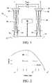
- FIG. 1is an overhead diagram of a binocular display showing a range of interpupillary distances at which left and right display screens can be viewed.
- FIG. 2is a graph of contrast as a function of viewing angle plotting an asymmetric distribution of contrast in opposite directions from a viewing angle of maximum contrast.
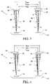
- FIG. 3is an overhead diagram of the binocular display depicting a direction of maximum contrast inclined to viewing axes of the display screens for a set of eyes spaced at an average interpupillary distance.
- FIG. 4is an overhead diagram of the same binocular display referenced with respect to a set of eyes spaced at a near maximum interpupillary distance accommodated by the display.
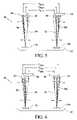
- FIG. 5is an overhead diagram of a modified binocular display with one display screen rotated with respect to another for balancing contrast referenced with respect to a set of eyes spaced at a near maximum interpupillary distance accommodated by the display.
- FIG. 6is an overhead diagram of the modified binocular display with one display screen rotated with respect to another for balancing contrast referenced with respect to a set of eyes spaced at a near minimum interpupillary distance accommodated by the display.
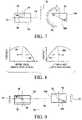
- FIG. 7is a schematic front of the two display screens, depicting the rotation of one screen with respect to the other for balancing contrast in a lateral plane.
- FIG. 8includes a pair of graphs showing asymmetric variations in contrast oriented in opposite directions between the left and right display screens.
- FIG. 9is a schematic front of the two relatively rotated display screens, depicting the offset of one screen with respect to the other for balancing contrast in a sagittal plane.
- a binocular display 10is depicted in FIG. 1 for purposes of reference.
- left and right display screens 14 and 16are visible within left and right eyeboxes 18 and 20 to left and right eyes 22 and 24 of a user.
- Optical systems 26 and 28preferably include focusing optics (not shown) for producing magnified virtual images of the display screens 14 and 16 visible within the eyeboxes 18 and 20 .
- the display screens 14 and 16are preferably compact high-resolution image generators capable of producing real images in a still or moving form containing more information than can be normally discerned by the human eye without magnification.
- Backlit liquid crystal displaysLCDs
- LCDsare preferred for these purposes, such as Kopin 230K CyberDisplays PN#KCD-QDLF-M from Kopin Corporation of Massachusetts mounted with a fixed interpupillary distance of 63.5 mm and a 24 degree diagonal field of view through a conventional optical lens system.
- LCDsbacklit liquid crystal displays
- PN#KCD-QDLF-Mfrom Kopin Corporation of Massachusetts mounted with a fixed interpupillary distance of 63.5 mm and a 24 degree diagonal field of view through a conventional optical lens system.
- LCOSliquid crystal on silicon
- OLEDsorganic light emitting diodes
- FEDsfield emission displays
- CRTscathode ray tubes
- Each of the display screens 14 and 16together with their respective optical systems 26 and 28 , forms a micro-display engine for relaying images produced by the display screens 14 and 16 to their respective eyeboxes 18 and 20 .
- Examples of such micro-display enginesare disclosed in U.S. Patent Application Publication 2005/0180021 (Travers), entitled “Micro-Display Engine”, which is hereby incorporated by reference.
- the display screens 14 and 16preferably include individually addressable pixels for producing images, such as those transferable from digital files or other image sources 30 , including both on-board or off-board drivers. Examples of such image sources include DVD players, A/V cell phones, multi-media players, and game consoles.
- the optical systems 26 and 28preferably include reflective focusing optics (not shown) for magnifying the images produced by the display screens 14 and 16 as virtual images and beamsplitters (not shown) for folding the optical paths between the display screens 14 and 16 and the eyeboxes 18 and 20 to provide more compact configurations.
- the eyeboxes 18 and 22define linear orthogonal dimensions within which the user's eyes 22 and can be relatively moved normal to the viewing (i.e. optical) axes 32 and 34 of the optical systems 26 and 28 while the images produced by the display screens 14 and 16 remain fully visible. Eyeboxes measuring at least 8 millimeters by 13 millimeters are preferred for most head-mounted binocular displays.
- the display screens 14 and 16can be viewed through a range of viewing angles within the eyeboxes 18 and 20 for accommodating a population of users having different interpupillary distances (IPDs) between their left and right eyes.
- IPDsinterpupillary distances
- the user's eyes 22 and 24 of FIG. 1which are located in the middle of their respective eyeboxes 18 and 20 , have a median interpupillary distance D MED of approximately 61 millimeters.
- Minimum and maximum interpupillary distances D MIN and D MAXspanning a range from approximately 52 centimeters to 72 millimeters, also fit within the eyeboxes 18 and 20 for accommodating most of the adult population.
- a characteristic of some display screens, particularly liquid crystal displays (LCDS)is that image contrast, which is the apparent difference in brightness between light and dark areas of an image, varies asymmetrically with viewing angle.
- image contrastwhich is the apparent difference in brightness between light and dark areas of an image
- a direction of peak contrast 38occurs at a viewing angle that is angularly separated from the viewing axis 32 or 34 through an inclination angle ⁇ (e.g., 12 degrees).
- ⁇e.g., 12 degrees
- the contrastdecreases asymmetrically for viewing angles on either side of the direction of peak contrast 38 . For example, as more negative viewing angles are approached, the contrast decreases quite gradually, but as more positive viewing angles are approached, the contrast decreases precipitously.
- FIGS. 3 and 4demonstrate how such an asymmetric variation in display contrast can be balanced between one user's eyes 22 and 24 at the median interpupillary distance D MED , yet the same asymmetric variation in display contrast can be imbalanced between another user's eyes 42 and 44 at other interpupillary distances such as at the maximum interpupillary distance D MAX shown in FIG. 4 .
- contrast depicted by shadingi.e., darker shading corresponding to higher contrast
- both of the user's eyes 22 and 24 in FIG. 3are presented with approximately the same contrast.
- the contrastis balanced between the left and right eyes 22 and 24 at the median interpupillary distance D MED .
- the left and right eyes 42 and 44are presented with different amounts of contrast. That is, the same asymmetric variation in contrast exhibited by the left and right display screens 14 and 16 results in the left eye 42 of the user having a maximum interpupillary distance D MAX being presented with much less contrast than the right eye 44 of the same user.
- the left eye of a user having a minimum interpupillary distance D MINwould be presented with much less contrast than the right eye of the same user.
- the contrast disparity between users' left and right eyesis attributable to the asymmetric distribution of contrast about the direction of peak contrast 38 but can be further aggravated by when the direction of peak contrast 38 is inclined as shown to the viewing axis 32 or 34 through the angle ⁇ .
- FIGS. 5 and 6depict an alternative binocular display 50 having similarly referenced elements in common with the binocular display 10 but having the display screen 14 , now referenced as 14 A, which is inverted (i.e. rotated through 180 degrees about its viewing axis 32 ) with respect to the orientation of the display screen 14 in the binocular display 10 .
- FIG. 7depicts the rotation of the display screen 14 A with respect to the display screen 16 through 180 degrees and shows the effect of the rotation on the direction of peak contrast 38 in the form of a reverse (left-to-right, right-to-left) symmetry, where the new direction of peak contrast 38 A extends in an opposite direction.
- the directions of peak contrast 38 and 38 A of the display screens 16 and 14 Aare both directed outwardly, the directions of peak contrast 38 and 38 A could also be directed inwardly (i.e., including lateral components directed toward each other), which may be preferable for some users.
- both displays 14 A and 16were manufactured substantially identically each with a designated top and bottom 52 and 54 , a common direction of peak contrast 38 , and a common profile of contrast asymmetry about the direction of peak contrast 38 .
- the contrast profile shown in FIG. 2is considered within a lateral plane 56 that includes the respective viewing axes 32 and 34 of the display screens 14 A and 16 . Accordingly, when the display screen 14 A is rotated as shown, the contrast profile of the display screen 14 A is reversed in the lateral plane 56 as shown in FIG. 8 .
- Signals for addressing individual pixels of the display screen 14 Amust be similarly rearranged so that the original bottom 54 of the display screen 14 A is addressed as its top and original top 52 of the display screen 14 A is addressed as its bottom.
- the variation of contrast with viewing angle in the lateral plane 56 of the binocular display 50is balanced between left and right eyes 62 and 64 or 66 and 68 over a range of different interpupillary distances.
- the user's eyes 62 and 64are spaced apart at the maximum interpupillary distance D MAX , where both eyes 62 and 64 are within regions of similar high contrast.
- the user's eyes 66 and 68are spaced apart at the minimum interpupillary distance D MIN , where both eyes 66 and 68 are within regions of similar low contrast.
- the balance in contrast between the left and right eyes 62 and 64 or 66 and 68avoids the eyestrain, headaches, and other discomforts associated with the type of imbalanced contrast apparent from the binocular display 10 for users with interpupillary distances that depart from average, such as shown in FIG. 4 .
- the contrast-balanced binocular display 50affords the possibility for extended viewing times over a wide range of interpupillary distances.
- the display screens 14 A and 16can be slightly inclined or offset to the eyeboxes 18 and 20 to more evenly balance contrast between the minimum and maximum interpupillary distances D MIN and D MAX .
- the asymmetric variation in contrast with viewing anglecan also include contrast asymmetries on either side of the direction of peak contrast 38 in an orthogonal sagittal plane 70 .
- Directional contrast asymmetries in the sagittal plane 70 of matching left and right display screens 14 and 16are generally not imbalanced by variations in interpupillary distances, but can be subject to imbalance by relatively rotating the two display screens 14 A and 16 as shown in FIGS. 5-7 .
- the left and right display screens 14 A and 16can be relatively translated in the direction of arrows 72 and 74 to reduce the imbalance.
- the relative translationreduces the overlayable working areas of the display screens to the areas 76 and 78 , which are balanced with respect to the lateral plane 56 .
- the inventioncan also be practiced as a binocular display having display screens that exhibit different asymmetric contrast variations about their directions of peak contrast.
- display screenscan be grouped in pairs according to their asymmetric contrast characteristics so that their contrast asymmetries with viewing angle approach mirror symmetry within a common lateral plane of the paired display screens. In this way, the changes in contrast within the left and right eyeboxes accompanying changes in interpupillary distances remain more substantially the same for both eyes of a user.
Landscapes
- Physics & Mathematics (AREA)
- Engineering & Computer Science (AREA)
- Multimedia (AREA)
- Signal Processing (AREA)
- General Physics & Mathematics (AREA)
- Optics & Photonics (AREA)
- Astronomy & Astrophysics (AREA)
- Liquid Crystal (AREA)
- Lenses (AREA)
- Testing, Inspecting, Measuring Of Stereoscopic Televisions And Televisions (AREA)
- Devices For Indicating Variable Information By Combining Individual Elements (AREA)
Abstract
Description
Claims (10)
Priority Applications (5)
| Application Number | Priority Date | Filing Date | Title |
|---|---|---|---|
| US11/306,616US7515344B2 (en) | 2006-01-04 | 2006-01-04 | Binocular display with improved contrast uniformity |
| EP06846708.3AEP1979781B1 (en) | 2006-01-04 | 2006-12-20 | Binocular display with improved contrast uniformity |
| JP2008549521AJP4866426B2 (en) | 2006-01-04 | 2006-12-20 | Binocular display device with improved contrast consistency |
| PCT/US2006/062358WO2007081648A2 (en) | 2006-01-04 | 2006-12-20 | Binocular display with improved contrast uniformity |
| CA2636283ACA2636283C (en) | 2006-01-04 | 2006-12-20 | Binocular display with improved contrast uniformity |
Applications Claiming Priority (1)
| Application Number | Priority Date | Filing Date | Title |
|---|---|---|---|
| US11/306,616US7515344B2 (en) | 2006-01-04 | 2006-01-04 | Binocular display with improved contrast uniformity |
Publications (2)
| Publication Number | Publication Date |
|---|---|
| US20070153374A1 US20070153374A1 (en) | 2007-07-05 |
| US7515344B2true US7515344B2 (en) | 2009-04-07 |
Family
ID=38224074
Family Applications (1)
| Application Number | Title | Priority Date | Filing Date |
|---|---|---|---|
| US11/306,616Active2027-04-12US7515344B2 (en) | 2006-01-04 | 2006-01-04 | Binocular display with improved contrast uniformity |
Country Status (5)
| Country | Link |
|---|---|
| US (1) | US7515344B2 (en) |
| EP (1) | EP1979781B1 (en) |
| JP (1) | JP4866426B2 (en) |
| CA (1) | CA2636283C (en) |
| WO (1) | WO2007081648A2 (en) |
Cited By (22)
| Publication number | Priority date | Publication date | Assignee | Title |
|---|---|---|---|---|
| US8467133B2 (en) | 2010-02-28 | 2013-06-18 | Osterhout Group, Inc. | See-through display with an optical assembly including a wedge-shaped illumination system |
| US8472120B2 (en) | 2010-02-28 | 2013-06-25 | Osterhout Group, Inc. | See-through near-eye display glasses with a small scale image source |
| US8477425B2 (en) | 2010-02-28 | 2013-07-02 | Osterhout Group, Inc. | See-through near-eye display glasses including a partially reflective, partially transmitting optical element |
| US8482859B2 (en) | 2010-02-28 | 2013-07-09 | Osterhout Group, Inc. | See-through near-eye display glasses wherein image light is transmitted to and reflected from an optically flat film |
| US8488246B2 (en) | 2010-02-28 | 2013-07-16 | Osterhout Group, Inc. | See-through near-eye display glasses including a curved polarizing film in the image source, a partially reflective, partially transmitting optical element and an optically flat film |
| US8814691B2 (en) | 2010-02-28 | 2014-08-26 | Microsoft Corporation | System and method for social networking gaming with an augmented reality |
| US9091851B2 (en) | 2010-02-28 | 2015-07-28 | Microsoft Technology Licensing, Llc | Light control in head mounted displays |
| US9097890B2 (en) | 2010-02-28 | 2015-08-04 | Microsoft Technology Licensing, Llc | Grating in a light transmissive illumination system for see-through near-eye display glasses |
| US9097891B2 (en) | 2010-02-28 | 2015-08-04 | Microsoft Technology Licensing, Llc | See-through near-eye display glasses including an auto-brightness control for the display brightness based on the brightness in the environment |
| US9129295B2 (en) | 2010-02-28 | 2015-09-08 | Microsoft Technology Licensing, Llc | See-through near-eye display glasses with a fast response photochromic film system for quick transition from dark to clear |
| US9128281B2 (en) | 2010-09-14 | 2015-09-08 | Microsoft Technology Licensing, Llc | Eyepiece with uniformly illuminated reflective display |
| US9134534B2 (en) | 2010-02-28 | 2015-09-15 | Microsoft Technology Licensing, Llc | See-through near-eye display glasses including a modular image source |
| US9182596B2 (en) | 2010-02-28 | 2015-11-10 | Microsoft Technology Licensing, Llc | See-through near-eye display glasses with the optical assembly including absorptive polarizers or anti-reflective coatings to reduce stray light |
| US9223134B2 (en) | 2010-02-28 | 2015-12-29 | Microsoft Technology Licensing, Llc | Optical imperfections in a light transmissive illumination system for see-through near-eye display glasses |
| US9229227B2 (en) | 2010-02-28 | 2016-01-05 | Microsoft Technology Licensing, Llc | See-through near-eye display glasses with a light transmissive wedge shaped illumination system |
| US9285589B2 (en) | 2010-02-28 | 2016-03-15 | Microsoft Technology Licensing, Llc | AR glasses with event and sensor triggered control of AR eyepiece applications |
| US9341843B2 (en) | 2010-02-28 | 2016-05-17 | Microsoft Technology Licensing, Llc | See-through near-eye display glasses with a small scale image source |
| US9366862B2 (en) | 2010-02-28 | 2016-06-14 | Microsoft Technology Licensing, Llc | System and method for delivering content to a group of see-through near eye display eyepieces |
| US9759917B2 (en) | 2010-02-28 | 2017-09-12 | Microsoft Technology Licensing, Llc | AR glasses with event and sensor triggered AR eyepiece interface to external devices |
| US10180572B2 (en) | 2010-02-28 | 2019-01-15 | Microsoft Technology Licensing, Llc | AR glasses with event and user action control of external applications |
| US10539787B2 (en) | 2010-02-28 | 2020-01-21 | Microsoft Technology Licensing, Llc | Head-worn adaptive display |
| US10860100B2 (en) | 2010-02-28 | 2020-12-08 | Microsoft Technology Licensing, Llc | AR glasses with predictive control of external device based on event input |
Families Citing this family (7)
| Publication number | Priority date | Publication date | Assignee | Title |
|---|---|---|---|---|
| FR2906899B1 (en)* | 2006-10-05 | 2009-01-16 | Essilor Int | DISPLAY DEVICE FOR STEREOSCOPIC VISUALIZATION. |
| US8909296B2 (en)* | 2007-05-14 | 2014-12-09 | Kopin Corporation | Mobile wireless display software platform for controlling other systems and devices |
| US8355671B2 (en)* | 2008-01-04 | 2013-01-15 | Kopin Corporation | Method and apparatus for transporting video signal over Bluetooth wireless interface |
| WO2009120984A1 (en) | 2008-03-28 | 2009-10-01 | Kopin Corporation | Handheld wireless display device having high-resolution display suitable for use as a mobile internet device |
| GB2484919A (en)* | 2010-10-25 | 2012-05-02 | Cambridge Silicon Radio | Directional display device arranged to display visual content toward a viewer |
| EP2699006A1 (en)* | 2012-08-16 | 2014-02-19 | ESSILOR INTERNATIONAL (Compagnie Générale d'Optique) | Pictures positioning on display elements |
| EP2972547B1 (en) | 2013-03-15 | 2024-10-23 | Immy Inc. | Head mounted display with non-pupil forming optical path |
Citations (10)
| Publication number | Priority date | Publication date | Assignee | Title |
|---|---|---|---|---|
| US5373857A (en) | 1993-06-18 | 1994-12-20 | Forte Technologies, Inc. | Head tracking apparatus |
| US6150998A (en) | 1994-12-30 | 2000-11-21 | Travers; Paul J. | Headset for presenting video and audio signals to a wearer |
| US6181367B1 (en) | 1997-05-13 | 2001-01-30 | New Light Industries, Ltd. | Video image viewing device and method |
| US6417970B1 (en) | 2000-06-08 | 2002-07-09 | Interactive Imaging Systems | Two stage optical system for head mounted display |
| US6788286B2 (en) | 2001-05-03 | 2004-09-07 | Interactive Imaging Systems, Inc. | Controller for graphical display |
| US6870532B2 (en) | 2000-06-09 | 2005-03-22 | Interactive Imaging Systems, Inc. | Image display |
| US6900778B1 (en)* | 1999-02-12 | 2005-05-31 | Canon Kabushiki Kaisha | Display apparatus and method with detecting elements allocated on side facing face of user and on lower side of display windows |
| US7190330B2 (en) | 2004-01-07 | 2007-03-13 | Icuiti Corporation | Virtual display headset |
| US7289085B2 (en)* | 2002-03-28 | 2007-10-30 | Siemens Ag | Combined instrument and structure provided with a combined instrument |
| US7397607B2 (en) | 2004-02-18 | 2008-07-08 | Vuzix Corporation | Micro-display engine |
Family Cites Families (3)
| Publication number | Priority date | Publication date | Assignee | Title |
|---|---|---|---|---|
| GB2294350A (en)* | 1994-10-21 | 1996-04-24 | Sharp Kk | Light source and display |
| JP3359152B2 (en)* | 1994-05-13 | 2002-12-24 | キヤノン株式会社 | Display device |
| JP2001311950A (en) | 2000-04-27 | 2001-11-09 | Victor Co Of Japan Ltd | Head-mounted display |
- 2006
- 2006-01-04USUS11/306,616patent/US7515344B2/enactiveActive
- 2006-12-20EPEP06846708.3Apatent/EP1979781B1/enactiveActive
- 2006-12-20WOPCT/US2006/062358patent/WO2007081648A2/enactiveApplication Filing
- 2006-12-20JPJP2008549521Apatent/JP4866426B2/enactiveActive
- 2006-12-20CACA2636283Apatent/CA2636283C/enactiveActive
Patent Citations (11)
| Publication number | Priority date | Publication date | Assignee | Title |
|---|---|---|---|---|
| US5373857A (en) | 1993-06-18 | 1994-12-20 | Forte Technologies, Inc. | Head tracking apparatus |
| US6150998A (en) | 1994-12-30 | 2000-11-21 | Travers; Paul J. | Headset for presenting video and audio signals to a wearer |
| US6181367B1 (en) | 1997-05-13 | 2001-01-30 | New Light Industries, Ltd. | Video image viewing device and method |
| US6900778B1 (en)* | 1999-02-12 | 2005-05-31 | Canon Kabushiki Kaisha | Display apparatus and method with detecting elements allocated on side facing face of user and on lower side of display windows |
| US6417970B1 (en) | 2000-06-08 | 2002-07-09 | Interactive Imaging Systems | Two stage optical system for head mounted display |
| US6636359B2 (en) | 2000-06-08 | 2003-10-21 | Interactive Imaging Systems, Inc. | Two stage optical magnification and image correction system |
| US6870532B2 (en) | 2000-06-09 | 2005-03-22 | Interactive Imaging Systems, Inc. | Image display |
| US6788286B2 (en) | 2001-05-03 | 2004-09-07 | Interactive Imaging Systems, Inc. | Controller for graphical display |
| US7289085B2 (en)* | 2002-03-28 | 2007-10-30 | Siemens Ag | Combined instrument and structure provided with a combined instrument |
| US7190330B2 (en) | 2004-01-07 | 2007-03-13 | Icuiti Corporation | Virtual display headset |
| US7397607B2 (en) | 2004-02-18 | 2008-07-08 | Vuzix Corporation | Micro-display engine |
Cited By (25)
| Publication number | Priority date | Publication date | Assignee | Title |
|---|---|---|---|---|
| US9182596B2 (en) | 2010-02-28 | 2015-11-10 | Microsoft Technology Licensing, Llc | See-through near-eye display glasses with the optical assembly including absorptive polarizers or anti-reflective coatings to reduce stray light |
| US10180572B2 (en) | 2010-02-28 | 2019-01-15 | Microsoft Technology Licensing, Llc | AR glasses with event and user action control of external applications |
| US8477425B2 (en) | 2010-02-28 | 2013-07-02 | Osterhout Group, Inc. | See-through near-eye display glasses including a partially reflective, partially transmitting optical element |
| US8482859B2 (en) | 2010-02-28 | 2013-07-09 | Osterhout Group, Inc. | See-through near-eye display glasses wherein image light is transmitted to and reflected from an optically flat film |
| US8488246B2 (en) | 2010-02-28 | 2013-07-16 | Osterhout Group, Inc. | See-through near-eye display glasses including a curved polarizing film in the image source, a partially reflective, partially transmitting optical element and an optically flat film |
| US8814691B2 (en) | 2010-02-28 | 2014-08-26 | Microsoft Corporation | System and method for social networking gaming with an augmented reality |
| US9091851B2 (en) | 2010-02-28 | 2015-07-28 | Microsoft Technology Licensing, Llc | Light control in head mounted displays |
| US9097890B2 (en) | 2010-02-28 | 2015-08-04 | Microsoft Technology Licensing, Llc | Grating in a light transmissive illumination system for see-through near-eye display glasses |
| US9097891B2 (en) | 2010-02-28 | 2015-08-04 | Microsoft Technology Licensing, Llc | See-through near-eye display glasses including an auto-brightness control for the display brightness based on the brightness in the environment |
| US9129295B2 (en) | 2010-02-28 | 2015-09-08 | Microsoft Technology Licensing, Llc | See-through near-eye display glasses with a fast response photochromic film system for quick transition from dark to clear |
| US10860100B2 (en) | 2010-02-28 | 2020-12-08 | Microsoft Technology Licensing, Llc | AR glasses with predictive control of external device based on event input |
| US9134534B2 (en) | 2010-02-28 | 2015-09-15 | Microsoft Technology Licensing, Llc | See-through near-eye display glasses including a modular image source |
| US8472120B2 (en) | 2010-02-28 | 2013-06-25 | Osterhout Group, Inc. | See-through near-eye display glasses with a small scale image source |
| US9229227B2 (en) | 2010-02-28 | 2016-01-05 | Microsoft Technology Licensing, Llc | See-through near-eye display glasses with a light transmissive wedge shaped illumination system |
| US8467133B2 (en) | 2010-02-28 | 2013-06-18 | Osterhout Group, Inc. | See-through display with an optical assembly including a wedge-shaped illumination system |
| US9285589B2 (en) | 2010-02-28 | 2016-03-15 | Microsoft Technology Licensing, Llc | AR glasses with event and sensor triggered control of AR eyepiece applications |
| US9329689B2 (en) | 2010-02-28 | 2016-05-03 | Microsoft Technology Licensing, Llc | Method and apparatus for biometric data capture |
| US9341843B2 (en) | 2010-02-28 | 2016-05-17 | Microsoft Technology Licensing, Llc | See-through near-eye display glasses with a small scale image source |
| US9366862B2 (en) | 2010-02-28 | 2016-06-14 | Microsoft Technology Licensing, Llc | System and method for delivering content to a group of see-through near eye display eyepieces |
| US9759917B2 (en) | 2010-02-28 | 2017-09-12 | Microsoft Technology Licensing, Llc | AR glasses with event and sensor triggered AR eyepiece interface to external devices |
| US9875406B2 (en) | 2010-02-28 | 2018-01-23 | Microsoft Technology Licensing, Llc | Adjustable extension for temple arm |
| US9223134B2 (en) | 2010-02-28 | 2015-12-29 | Microsoft Technology Licensing, Llc | Optical imperfections in a light transmissive illumination system for see-through near-eye display glasses |
| US10268888B2 (en) | 2010-02-28 | 2019-04-23 | Microsoft Technology Licensing, Llc | Method and apparatus for biometric data capture |
| US10539787B2 (en) | 2010-02-28 | 2020-01-21 | Microsoft Technology Licensing, Llc | Head-worn adaptive display |
| US9128281B2 (en) | 2010-09-14 | 2015-09-08 | Microsoft Technology Licensing, Llc | Eyepiece with uniformly illuminated reflective display |
Also Published As
| Publication number | Publication date |
|---|---|
| CA2636283A1 (en) | 2007-07-19 |
| EP1979781B1 (en) | 2020-04-15 |
| CA2636283C (en) | 2011-11-15 |
| JP2009522619A (en) | 2009-06-11 |
| EP1979781A4 (en) | 2011-11-16 |
| WO2007081648A2 (en) | 2007-07-19 |
| JP4866426B2 (en) | 2012-02-01 |
| EP1979781A2 (en) | 2008-10-15 |
| WO2007081648A3 (en) | 2008-11-27 |
| US20070153374A1 (en) | 2007-07-05 |
Similar Documents
| Publication | Publication Date | Title |
|---|---|---|
| CA2636283C (en) | Binocular display with improved contrast uniformity | |
| US11551602B2 (en) | Non-uniform resolution, large field-of-view headworn display | |
| EP3411745B1 (en) | Compact near-eye display optics | |
| US10133074B2 (en) | Compact near-eye display optics for higher optical performance | |
| Rolland et al. | Head-mounted display systems | |
| US10701351B2 (en) | Virtual image display device | |
| JP4637863B2 (en) | Improvement of image quality of 3D image display device | |
| JP4492851B2 (en) | Parallax barrier and multiple display | |
| EP3120187A1 (en) | Directional backlight | |
| JP2004206089A (en) | Multiple view display | |
| JP5104870B2 (en) | LCD shutter glasses | |
| CN111754882A (en) | A display screen and VR glasses | |
| US20120139909A1 (en) | 3d display apparatus and method of displaying 3d images | |
| US20230314805A1 (en) | Optic system for head wearable devices | |
| JP2007513360A (en) | Improvement of color ratio in 3D image display | |
| US20250013069A1 (en) | Light field display device and head-mounted display | |
| Veron et al. | Head-mounted displays for virtual reality | |
| CN205751379U (en) | Display device | |
| WO2022064564A1 (en) | Head-mounted display | |
| JP4927208B2 (en) | Stereoscopic image display device | |
| JPH0749464A (en) | Head installation type display device | |
| EP1894055A1 (en) | Stereoscopic viewing apparatus | |
| US20180038996A1 (en) | Mitigation of screen door effect in head-mounted displays | |
| US11172718B2 (en) | Wearable display device | |
| WO2013061439A1 (en) | Three-dimensional video display device |
Legal Events
| Date | Code | Title | Description |
|---|---|---|---|
| AS | Assignment | Owner name:ICUITI CORPORATION, NEW YORK Free format text:ASSIGNMENT OF ASSIGNORS INTEREST;ASSIGNOR:TRAVERS, PAUL J.;REEL/FRAME:017074/0413 Effective date:20060103 | |
| AS | Assignment | Owner name:VUZIX CORPORATION, NEW YORK Free format text:CHANGE OF NAME;ASSIGNOR:ICUITI CORPORATION;REEL/FRAME:019991/0932 Effective date:20070912 | |
| STCF | Information on status: patent grant | Free format text:PATENTED CASE | |
| CC | Certificate of correction | ||
| AS | Assignment | Owner name:LC CAPITAL MASTER FUND LTD, NEW YORK Free format text:SECURITY AGREEMENT;ASSIGNOR:VUZIX CORPORATION;REEL/FRAME:025573/0632 Effective date:20101223 | |
| AS | Assignment | Owner name:TDG ACQUISITION COMPANY, LLC, PENNSYLVANIA Free format text:ASSIGNMENT OF ASSIGNORS INTEREST;ASSIGNOR:VUZIX CORPORATION;REEL/FRAME:028426/0066 Effective date:20120615 Owner name:VUZIX CORPORATION, NEW YORK Free format text:SECURITY AGREEMENT;ASSIGNOR:LC CAPITAL MASTER FUND, LTD.;REEL/FRAME:028429/0913 Effective date:20120615 | |
| FPAY | Fee payment | Year of fee payment:4 | |
| FPAY | Fee payment | Year of fee payment:8 | |
| MAFP | Maintenance fee payment | Free format text:PAYMENT OF MAINTENANCE FEE, 12TH YR, SMALL ENTITY (ORIGINAL EVENT CODE: M2553); ENTITY STATUS OF PATENT OWNER: SMALL ENTITY Year of fee payment:12 | |
| AS | Assignment | Owner name:SQN VENTURE INCOME FUND II, LP, NEW HAMPSHIRE Free format text:NO LIEN COVENANT;ASSIGNOR:TDG ACQUISITION COMPANY LLC;REEL/FRAME:053966/0705 Effective date:20200930 |