US7514899B2 - Method and apparatus for optical wireless charging - Google Patents
Method and apparatus for optical wireless chargingDownload PDFInfo
- Publication number
- US7514899B2 US7514899B2US11/283,304US28330405AUS7514899B2US 7514899 B2US7514899 B2US 7514899B2US 28330405 AUS28330405 AUS 28330405AUS 7514899 B2US7514899 B2US 7514899B2
- Authority
- US
- United States
- Prior art keywords
- light
- charger
- light source
- accordance
- portable electronic
- Prior art date
- Legal status (The legal status is an assumption and is not a legal conclusion. Google has not performed a legal analysis and makes no representation as to the accuracy of the status listed.)
- Expired - Fee Related, expires
Links
- 230000003287optical effectEffects0.000titleclaimsabstractdescription37
- 238000000034methodMethods0.000titleclaimsdescription12
- 238000001514detection methodMethods0.000claimsdescription5
- 238000004891communicationMethods0.000claimsdescription4
- 230000003213activating effectEffects0.000claims1
- 230000011664signalingEffects0.000claims1
- 238000013459approachMethods0.000description5
- 238000010586diagramMethods0.000description4
- 230000001939inductive effectEffects0.000description4
- 238000006243chemical reactionMethods0.000description3
- 230000008878couplingEffects0.000description3
- 238000010168coupling processMethods0.000description3
- 238000005859coupling reactionMethods0.000description3
- 238000012986modificationMethods0.000description2
- 230000004048modificationEffects0.000description2
- 230000001105regulatory effectEffects0.000description2
- 230000035945sensitivityEffects0.000description2
- 239000003990capacitorSubstances0.000description1
- 230000001413cellular effectEffects0.000description1
- 229910021419crystalline siliconInorganic materials0.000description1
- 230000005611electricityEffects0.000description1
- 230000005672electromagnetic fieldEffects0.000description1
- 238000005516engineering processMethods0.000description1
- 238000001914filtrationMethods0.000description1
- 239000000446fuelSubstances0.000description1
- 238000003384imaging methodMethods0.000description1
- 238000003780insertionMethods0.000description1
- 230000037431insertionEffects0.000description1
- 230000003993interactionEffects0.000description1
- 238000010295mobile communicationMethods0.000description1
- 230000008569processEffects0.000description1
- 238000012546transferMethods0.000description1
Images


Classifications
- H—ELECTRICITY
- H02—GENERATION; CONVERSION OR DISTRIBUTION OF ELECTRIC POWER
- H02J—CIRCUIT ARRANGEMENTS OR SYSTEMS FOR SUPPLYING OR DISTRIBUTING ELECTRIC POWER; SYSTEMS FOR STORING ELECTRIC ENERGY
- H02J7/00—Circuit arrangements for charging or depolarising batteries or for supplying loads from batteries
- H02J7/34—Parallel operation in networks using both storage and other DC sources, e.g. providing buffering
- H02J7/35—Parallel operation in networks using both storage and other DC sources, e.g. providing buffering with light sensitive cells
- H—ELECTRICITY
- H02—GENERATION; CONVERSION OR DISTRIBUTION OF ELECTRIC POWER
- H02J—CIRCUIT ARRANGEMENTS OR SYSTEMS FOR SUPPLYING OR DISTRIBUTING ELECTRIC POWER; SYSTEMS FOR STORING ELECTRIC ENERGY
- H02J50/00—Circuit arrangements or systems for wireless supply or distribution of electric power
- H02J50/30—Circuit arrangements or systems for wireless supply or distribution of electric power using light, e.g. lasers
- H—ELECTRICITY
- H02—GENERATION; CONVERSION OR DISTRIBUTION OF ELECTRIC POWER
- H02J—CIRCUIT ARRANGEMENTS OR SYSTEMS FOR SUPPLYING OR DISTRIBUTING ELECTRIC POWER; SYSTEMS FOR STORING ELECTRIC ENERGY
- H02J50/00—Circuit arrangements or systems for wireless supply or distribution of electric power
- H02J50/70—Circuit arrangements or systems for wireless supply or distribution of electric power involving the reduction of electric, magnetic or electromagnetic leakage fields
- H—ELECTRICITY
- H02—GENERATION; CONVERSION OR DISTRIBUTION OF ELECTRIC POWER
- H02J—CIRCUIT ARRANGEMENTS OR SYSTEMS FOR SUPPLYING OR DISTRIBUTING ELECTRIC POWER; SYSTEMS FOR STORING ELECTRIC ENERGY
- H02J50/00—Circuit arrangements or systems for wireless supply or distribution of electric power
- H02J50/80—Circuit arrangements or systems for wireless supply or distribution of electric power involving the exchange of data, concerning supply or distribution of electric power, between transmitting devices and receiving devices
- H—ELECTRICITY
- H02—GENERATION; CONVERSION OR DISTRIBUTION OF ELECTRIC POWER
- H02J—CIRCUIT ARRANGEMENTS OR SYSTEMS FOR SUPPLYING OR DISTRIBUTING ELECTRIC POWER; SYSTEMS FOR STORING ELECTRIC ENERGY
- H02J50/00—Circuit arrangements or systems for wireless supply or distribution of electric power
- H02J50/90—Circuit arrangements or systems for wireless supply or distribution of electric power involving detection or optimisation of position, e.g. alignment
- Y—GENERAL TAGGING OF NEW TECHNOLOGICAL DEVELOPMENTS; GENERAL TAGGING OF CROSS-SECTIONAL TECHNOLOGIES SPANNING OVER SEVERAL SECTIONS OF THE IPC; TECHNICAL SUBJECTS COVERED BY FORMER USPC CROSS-REFERENCE ART COLLECTIONS [XRACs] AND DIGESTS
- Y02—TECHNOLOGIES OR APPLICATIONS FOR MITIGATION OR ADAPTATION AGAINST CLIMATE CHANGE
- Y02E—REDUCTION OF GREENHOUSE GAS [GHG] EMISSIONS, RELATED TO ENERGY GENERATION, TRANSMISSION OR DISTRIBUTION
- Y02E10/00—Energy generation through renewable energy sources
- Y02E10/50—Photovoltaic [PV] energy
- Y02E10/56—Power conversion systems, e.g. maximum power point trackers
- Y—GENERAL TAGGING OF NEW TECHNOLOGICAL DEVELOPMENTS; GENERAL TAGGING OF CROSS-SECTIONAL TECHNOLOGIES SPANNING OVER SEVERAL SECTIONS OF THE IPC; TECHNICAL SUBJECTS COVERED BY FORMER USPC CROSS-REFERENCE ART COLLECTIONS [XRACs] AND DIGESTS
- Y10—TECHNICAL SUBJECTS COVERED BY FORMER USPC
- Y10S—TECHNICAL SUBJECTS COVERED BY FORMER USPC CROSS-REFERENCE ART COLLECTIONS [XRACs] AND DIGESTS
- Y10S136/00—Batteries: thermoelectric and photoelectric
- Y10S136/291—Applications
Definitions
- This inventionrelates generally to the field of portable electronic devices. More particularly, this invention relates to a battery charger for portable electronic devices.
- Portable electronic devicessuch as mobile cellular telephones, personal digital assistants (PDA's), digital cameras, portable audio devices (MP3 players, CD players, radios etc.) and portable video devices (recorders and players), are powered by electrical batteries. Large batteries are prohibitively heavy and/or bulky, so battery capacities are often around 1 amp hour (Ah), which provides an acceptable usage time for devices with low power consumption. Often these batteries are rechargeable.
- Removeable batteriesmay be of standard size. This allows the batteries to be removed and placed in an external battery charger.
- many devicesuse custom sized batteries that are not removed from the electronic device for charging.
- dedicated chargersare used.
- chargersthere is very little standardization of chargers, and consequently different brands of portable device and different types of portable device have different charges.
- a usermay therefore be required to have a range of different chargers, all competing for space and electrical power outlets. The problem is exacerbated if the user needs to charge the devices at multiple locations, for example at the home and at the office, or if the user travels often.
- a universal chargermight be fitted with detachable charging plugs to fit a number of portable devices.
- the source of power for the chargermight be a power line, a computer USB port, a solar cell, a fuel cell or even a mechanically turned dynamo. This approach still results in a duplication of components (the charging plugs).
- a further approach, which eliminates the use of charging plugs,is the use of an inductive coupling (magnetic field interaction) to provide a wireless coupling to the portable device.
- a charging padcontains a number of electrical coils that carry an electrical current.
- the portable devicealso contains an electrical coil. When the portable device is place on the charging pad, an electrical current is induced in the coil of the portable device; this current is used to charge the battery.
- inductive chargingis combined with a solar cell.
- the solar cellreceives ambient light and converts it to electricity to slowly charge a battery in the charger.
- An inductive couplingis used to transfer charge to the portable device when it is placed close to the charger.
- an inductive chargerhas advantages, one disadvantage is that the electromagnetic field may interfere with other electronic devices, of magnetically recorded media (such as credit cards or video tapes).
- FIG. 1is a block diagram of wireless optical charger and a portable electronic device consistent with certain embodiments of the invention.
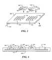
- FIG. 2is a diagrammatic represent of a wireless optical charger consistent with certain embodiments of the invention.
- FIG. 3is cross-sectional view of a wireless optical charger consistent with certain embodiments of the invention.
- FIG. 4is a circuit diagram of a proximity sensor circuit of an optical charger consistent with certain embodiments of the invention.
- FIG. 5is a flow chart of a method for charging a portable electronic device consistent with certain embodiments of the invention.
- FIG. 6is cross-sectional view of a wireless optical charger consistent with certain embodiments of the invention.
- the present inventionrelates to a method and apparatus for wireless optical charging of a portable electronic device.
- portable electronic devicesinclude a mobile communication device (such as radio, mobile telephone or walkie-talkie), a portable computing device (such as a personal digital assistant or palmtop or laptop computer), a portable entertainment device (such as a music player, game console or toy), a personal care item (such as a toothbrush, shaver, hair curler, hair rollers), a portable imaging device (such as a video recorder or camera), a consumer device (such as a flashlight, clock or fan) or a battery or battery-pack for insertion into any of the above.
- a mobile communication devicesuch as radio, mobile telephone or walkie-talkie
- a portable computing devicesuch as a personal digital assistant or palmtop or laptop computer
- a portable entertainment devicesuch as a music player, game console or toy
- a personal care itemsuch as a toothbrush, shaver, hair curler, hair rollers
- a portable imaging devicesuch as
- One embodiment of the inventionrelates to a system for transferring electrical charge to a portable device.
- the systemincludes a first conversion means for converting a first electrical signal into an optical signal and a second conversion means for receiving the optical signal and converting it to a second electrical signal for charging the portable device.
- the first conversion meansmay be an array of light emitting diodes, or some other light source, mounted in charger, while the second means may be a photovoltaic cell mounted on the portable device.
- the first electrical signalmay be derived from an A.C. power outlet, for example, or some other source.
- FIG. 1is a block diagram of wireless charger 100 and portable electronic device 102 consistent with certain embodiments of the invention.
- the charger 100includes a high power light source 104 , such as one or more high power light emitting diodes (LED's), which is operable to emit high intensity light that falls onto one or more photovoltaic cells 106 of the portable device 102 .
- the light sourcewill generally be referred to as comprising one or more LED's, but it is to be understood that other light sources may be used.
- the LED'smay be infrared LED's so as to increase eye safety. For example, the LED's may produce light with wavelengths in the range 700 nm-1000 nm.
- the photovoltaic cell 106(also called a solar cell, a photo-detector or an optical detector) converts at least a portion of the light into an electrical signal that is coupled to a charging circuit and battery (or other charge storage device) 108 .
- the batterymay be one or more voltaic cells.
- a variety of suitable charging circuitsare well known to those of ordinary skill in the art.
- the photovoltaic cell 106may be positioned in the casing of the portable device 102 .
- the sensitivity of the photovoltaic cell 106may be chosen to match the wavelengths of the light emitted from the light source 104 .
- the photovoltaic cellsare c-Si photovoltaic cells, which have peak sensitivity for light with wavelengths around 950 nm.
- a microcontroller 110 of the portable deviceis used to control the charging circuit 108 .
- the high power LED's 104are driven by an LED driving circuit 112 that, in turn, is powered from power supply 114 .
- the power supplymay be derived from an external power source, such as a power line, or other source (such as a battery with a slow solar charger or a vehicle DC power outlet), and may supply direct or alternating current.
- Driving circuits for large numbers of LED'sare well known, both for rectified DC or AC power line power supplies.
- the charger 100includes a proximity sensor and associated regulating circuit 116 .
- the proximity sensoris used to detect the proximity or removal of a portable device from the charger. When the portable device is in the proximity of the charger 100 , the light source is turned on. When the portable device is removed, the light source is turned off. This reduces the amount of power consumed by the charger and also increases eye safety.
- the proximity sensormay be a reflective sensor, with an emitter and a receiver.
- the sensor's emitteris driven by a modulated signal and its detector regulation circuit includes a band-pass filter in order to reduce the influence of light from the high power LED's of the charging light source.
- the LED'smay have a constant intensity or they may be modulated at a different rate from the sensor. For example, the LED's may be modulated at a much lower frequency.
- a microcontroller 118responsive to the proximity sensor and regulating circuit 116 may be used to control the LED driving circuit 112 .
- the portable device 102may contain a wireless communication circuit 120 , such as a Bluetooth or IrDA interface. If the charger 100 has a corresponding communication circuit 122 , the portable device and the charger may interact. In particular, the portable device 102 may communicate that its battery is fully charged and the charger may be turned off to conserve power or prevent overcharging.
- a wireless communication circuit 120such as a Bluetooth or IrDA interface.
- FIG. 2is a diagrammatic represent of a wireless optical charger 100 .
- the chargerhas two charging areas, allowing two portable devices 102 to be charged simultaneously.
- the chargermay have one or more charging areas.
- Each charging areaincludes an array of light sources 104 , such as high power LED's, and a proximity sensor 116 (such an optical reflectance detector).
- a proximity sensor 116such an optical reflectance detector.
- the portable electronic device 102is placed with its photovoltaic cell 106 facing the light source 104 so that the photovoltaic cell 106 can receive light from the light source.
- the light sourceilluminates the photovoltaic cell 106 of the portable device and charges the battery of the portable device.
- Power supply 124may come from a wall power outlet or from some other power source.
- the LED's 104 , proximity sensors 116 and associated circuitryare housed in housing 202 .
- the housingmay take the form of a pad for placing on a horizontal surface.
- the upper surface of the housing 202is designed to support the portable device 102 .
- the array of LED'smay be configured in a vertical plane and a portable device placed adjacent to the housing for charging.
- One proximity sensormay be used for each group of LED's, or each LED may have its own sensor.
- a charging LEDis used as the emitter for an optical reflectance proximity sensor. The photo-detector of the proximity sensor is shielded from light transmitted on a direct path from the charging LED.
- FIG. 3is a simplified cross-sectional view of a wireless optical charger consistent with certain embodiments of the invention.
- light emitting diodes (LED's) 104emit light that passes through emitter lenses 302 . Some of this light falls on the photovoltaic cell of the portable device.
- the LED's 104are mounted on a circuit board 112 .
- the LED'smay be discrete components, or may be formed together in an array.
- An encapsulating layer or cover 304protects the circuit board, helps to retain the emitter lenses 302 and provides a surface on which the portable device may be placed.
- Proximity sensor 116 and associated circuitryare located close to the array of LED's.
- the chargermay be rigid or flexible.
- the proximity sensormay be an optical reflectance sensor, such as an HSDL-9100 Miniature Surface-Mount Proximity Sensor manufactured by Agilent Technology, or some other form of detector such as an ultrasonic, pressure, capacitance or inductance detector.
- an optical reflectance detectorWhen an optical reflectance detector is used, it should be configured to discriminate between reflected light and other light sources, such as the LED's, sunlight, incandescent light and fluorescent light.
- FIG. 4is a circuit diagram of a proximity sensor circuit of an optical charger consistent with certain embodiments of the invention.
- the light source 402 of the proximity sensoris driven by a modulated drive circuit 404 , such as a pulse generator.
- the modulation frequencyis selected to be different from the frequencies of any ambient sources.
- a photo-detector 408such as a photodiode or phototransistor.
- the photo-detectorconverts the light into an electrical signal that is passed through a filter and amplifier circuit 410 to provide a signal 412 for detection.
- the photo-detector 408is reverse biased from D.C. source 414 through biasing resistor 416 . This makes the photo-diode function as a voltage source rather than a current source.
- the capacitors 418 and 420 , the resistor 422 and the operational amplifier 424 of the circuit 410are selected such that the filter has a high-pass or band-pass characteristic.
- the operational amplifieris powered from D.C. sources 414 and 426 .
- Other filtering circuitswill be apparent to those of ordinary skill in the art.
- the photo-detector 408receives reflected light 428 from the portable device and ambient light 430 .
- the ambient light 430has a D.C. component due to sunlight and A.C. components from light sources such as florescent lights and incandescent lights.
- the light source 402is amplitude modulated at a frequency in the region of 20 KHz.
- the A.C. components of the ambient lightare typically modulated at much lower frequencies, so the circuit 410 removes most of the signal due to ambient light.
- the output signal 414thus contains signal components due mainly to the reflected light 428 .
- the signal 414can be passed to a threshold detection circuit, for example, and used to control the LED's of the charger.
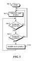
- FIG. 5is a flow chart of a method for charging a portable electronic device consistent with certain embodiments of the invention.
- the light source of the chargeris initially turned off at block 504 . This is the default state.
- decision block 506a check is made to determine if a portable electronic device is detected close to the light source of the charger. This check may be made by comparing a proximity sensor signal to a threshold. The result may be polled by the microcontroller or used to generate an interrupt in the microcontroller. If no device is detected, as depicted by the negative branch from decision block 506 , flow returns to block 504 .
- decision block 508a check is made to determine if the portable electronic device is fully charged. This check may be determined by communication between the charger and the device using a wireless interface, such as a Bluetooth radio link. If the device is not fully charged, as depicted by the negative branch from decision block 508 , or if no check is made, the light source is powered (switched on) at block 510 to start the charging process by illuminating the photovoltaic cell of the portable electronic device. Finally, flow returns to decision block 506 . If the device is fully charged, as depicted by the positive branch from decision block 508 , flow returns to block 504 and the light source of the charger is switched off to conserve power.
- a wireless interfacesuch as a Bluetooth radio link
- FIG. 6is cross-sectional view of a wireless optical charger consistent with certain embodiments of the invention.
- the charger 100includes a housing 202 that supports an array of light sources 104 and a proximity sensor 116 .
- the proximity sensoris coupled to the light source and is operable to detect when a portable electronic device 102 is close to the light source.
- the light sourceis activated to emit light that falls on a photovoltaic cell 106 of the portable device 102 .
- the proximity sensor 116may be, for example, a pressure switch or an optical reflectance detector.
Landscapes
- Engineering & Computer Science (AREA)
- Power Engineering (AREA)
- Computer Networks & Wireless Communication (AREA)
- Physics & Mathematics (AREA)
- Electromagnetism (AREA)
- Optics & Photonics (AREA)
- Charge And Discharge Circuits For Batteries Or The Like (AREA)
Abstract
Description
Claims (22)
Priority Applications (1)
| Application Number | Priority Date | Filing Date | Title |
|---|---|---|---|
| US11/283,304US7514899B2 (en) | 2005-11-18 | 2005-11-18 | Method and apparatus for optical wireless charging |
Applications Claiming Priority (1)
| Application Number | Priority Date | Filing Date | Title |
|---|---|---|---|
| US11/283,304US7514899B2 (en) | 2005-11-18 | 2005-11-18 | Method and apparatus for optical wireless charging |
Publications (2)
| Publication Number | Publication Date |
|---|---|
| US20070114967A1 US20070114967A1 (en) | 2007-05-24 |
| US7514899B2true US7514899B2 (en) | 2009-04-07 |
Family
ID=38052848
Family Applications (1)
| Application Number | Title | Priority Date | Filing Date |
|---|---|---|---|
| US11/283,304Expired - Fee RelatedUS7514899B2 (en) | 2005-11-18 | 2005-11-18 | Method and apparatus for optical wireless charging |
Country Status (1)
| Country | Link |
|---|---|
| US (1) | US7514899B2 (en) |
Cited By (26)
| Publication number | Priority date | Publication date | Assignee | Title |
|---|---|---|---|---|
| US20060092407A1 (en)* | 2004-10-29 | 2006-05-04 | Wee-Sin Tan | Method and apparatus for identifying a sensed light environment |
| US20080211458A1 (en)* | 2007-03-01 | 2008-09-04 | Lawther Joel S | Charging display system |
| US20090273309A1 (en)* | 2008-04-30 | 2009-11-05 | Visteon Global Technologies, Inc. | Photovoltaic charging system |
| US20100151808A1 (en)* | 2008-11-21 | 2010-06-17 | Qualcomm Incorporated | Reduced jamming between receivers and wireless power transmitters |
| US20100290215A1 (en)* | 2009-05-12 | 2010-11-18 | Kimball International, Inc. | Furniture with wireless power |
| US20110241691A1 (en)* | 2010-03-31 | 2011-10-06 | Chi Mei Communication Systems, Inc. | Testing device and testing method employing the same |
| US20120274470A1 (en)* | 2009-12-11 | 2012-11-01 | Sandvick Warren J | Food safety indicator |
| US20140009261A1 (en)* | 2011-08-26 | 2014-01-09 | Panasonic Corporation | In-vehicle charger |
| US20140132201A1 (en)* | 2012-11-09 | 2014-05-15 | City University Of Hong Kong | Wireless optical charging and power supply |
| US20140265998A1 (en)* | 2013-03-15 | 2014-09-18 | Sandia Corporation | Power transfer for mobile electronic devices |
| US20140285033A1 (en)* | 2013-03-20 | 2014-09-25 | Nokia Corporation | Method, apparatus, and computer program product for powering electronics in smart covers |
| US8994224B2 (en) | 2012-01-27 | 2015-03-31 | Building Materials Investment Corporation | Solar roof shingles and underlayment with wireless power transfer |
| US9124308B2 (en) | 2009-05-12 | 2015-09-01 | Kimball International, Inc. | Furniture with wireless power |
| CN105022475A (en)* | 2014-04-16 | 2015-11-04 | 凌通科技股份有限公司 | Photovoltaic power generation interaction device and photovoltaic power generation interaction system |
| US9369008B2 (en) | 2013-03-20 | 2016-06-14 | Nokia Technologies Oy | Method, apparatus, and computer program product for powering electronic devices |
| US9379543B2 (en) | 2012-04-10 | 2016-06-28 | Sol Chip Ltd. | Integrated circuit energy harvester |
| JP2016534703A (en)* | 2013-10-01 | 2016-11-04 | インテル コーポレイション | Universal ultrasonic wireless charging |
| CN108134416A (en)* | 2017-12-21 | 2018-06-08 | 同济大学 | Mobile optics charging system and application based on time division multiplexing and pulse width modulation |
| US10027181B2 (en) | 2015-09-29 | 2018-07-17 | X-Celeprint Limited | Layers of safety and failsafe capability for operation of class IV laser in consumer electronics devices |
| US10283952B2 (en) | 2017-06-22 | 2019-05-07 | Bretford Manufacturing, Inc. | Rapidly deployable floor power system |
| US10463572B2 (en) | 2017-07-07 | 2019-11-05 | Neuroderm, Ltd. | Device for subcutaneous delivery of fluid medicament |
| US10468906B2 (en) | 2016-12-29 | 2019-11-05 | Analog Devices Global | Optical charging system with integrated sensor and power receiver |
| US20220103018A1 (en)* | 2015-07-16 | 2022-03-31 | Wi-Charge Ltd. | System for optical wireless power supply |
| US11779697B2 (en) | 2017-07-07 | 2023-10-10 | Neuroderm, Ltd. | Device for subcutaneous delivery of fluid medicament |
| US12132342B2 (en) | 2021-05-04 | 2024-10-29 | Tectus Corporation | Contact lens charging circuit |
| US20250042549A1 (en)* | 2023-08-03 | 2025-02-06 | B/E Aerospace, Inc. | Wireless power passenger seat |
Families Citing this family (46)
| Publication number | Priority date | Publication date | Assignee | Title |
|---|---|---|---|---|
| US7816886B2 (en) | 2006-03-08 | 2010-10-19 | Eveready Battery Company, Inc. | Battery charger |
| JP4550015B2 (en)* | 2006-06-13 | 2010-09-22 | シャープ株式会社 | Optical space communication equipment |
| US20070294546A1 (en)* | 2006-06-19 | 2007-12-20 | Apple Computer, Inc. | Host device shutdown system |
| US20090032720A1 (en)* | 2007-07-30 | 2009-02-05 | Lee Atkinson | System with optical energy producing structure and electrical device comprising solar cell |
| TWI347724B (en)* | 2007-11-23 | 2011-08-21 | Compal Communications Inc | Method and apparatus for wireless charging |
| US20130093381A1 (en)* | 2008-05-27 | 2013-04-18 | Voltstar Technologies, Inc. | Energy saving cable assembly |
| US8447366B2 (en)* | 2008-05-30 | 2013-05-21 | T-Mobile Usa, Inc. | Charging station for mobile devices that allows access to device services |
| US8497657B2 (en)* | 2008-06-27 | 2013-07-30 | Microsoft Corporation | Docking station for electronic device |
| US8626249B2 (en)* | 2008-08-12 | 2014-01-07 | T-Mobile Usa, Inc. | Charging station that operates as an intermediary device between mobile devices and other devices |
| US10211664B2 (en) | 2010-07-09 | 2019-02-19 | Industrial Technology Research Institute | Apparatus for transmission of wireless energy |
| US9438063B2 (en) | 2010-07-09 | 2016-09-06 | Industrial Technology Research Institute | Charge apparatus |
| US8692505B2 (en)* | 2010-07-09 | 2014-04-08 | Industrial Technology Research Institute | Charge apparatus |
| US8525688B2 (en)* | 2011-01-10 | 2013-09-03 | Palm, Inc. | Proximity detection alarm for an inductively charged mobile computing device |
| DE102011076963A1 (en)* | 2011-06-06 | 2012-12-06 | Robert Bosch Gmbh | Battery pack with a separate power supply device for a wireless communication device of the battery pack |
| US9354748B2 (en) | 2012-02-13 | 2016-05-31 | Microsoft Technology Licensing, Llc | Optical stylus interaction |
| US9460029B2 (en) | 2012-03-02 | 2016-10-04 | Microsoft Technology Licensing, Llc | Pressure sensitive keys |
| US8873227B2 (en) | 2012-03-02 | 2014-10-28 | Microsoft Corporation | Flexible hinge support layer |
| US9870066B2 (en) | 2012-03-02 | 2018-01-16 | Microsoft Technology Licensing, Llc | Method of manufacturing an input device |
| US9075566B2 (en) | 2012-03-02 | 2015-07-07 | Microsoft Technoogy Licensing, LLC | Flexible hinge spine |
| KR101901720B1 (en)* | 2012-04-02 | 2018-11-13 | 삼성전자주식회사 | Method for interworing with dummy device and an electronic device thereof |
| CN103390911B (en)* | 2012-05-10 | 2016-02-24 | 航天信息股份有限公司 | Utilize the methods, devices and systems that light signal charges to active card |
| US20130300590A1 (en) | 2012-05-14 | 2013-11-14 | Paul Henry Dietz | Audio Feedback |
| US9142999B2 (en)* | 2012-07-13 | 2015-09-22 | Qualcomm Incorporated | Systems, methods, and apparatus for small device wireless charging modes |
| US8964379B2 (en) | 2012-08-20 | 2015-02-24 | Microsoft Corporation | Switchable magnetic lock |
| TWI566501B (en)* | 2012-12-20 | 2017-01-11 | 鴻海精密工業股份有限公司 | Charger |
| CN105493645A (en) | 2013-03-15 | 2016-04-13 | 芬斯克斯有限公司 | Method and apparatus for controlling heat in power conversion systems |
| US20140268563A1 (en)* | 2013-03-15 | 2014-09-18 | Finsix Corporation | Method and apparatus for controlling heat in power conversion systems |
| CN103595083B (en)* | 2013-06-07 | 2016-08-24 | 闽南师范大学 | A kind of desktop type general optical coupling wireless charger and application thereof |
| US9553475B2 (en) | 2013-06-20 | 2017-01-24 | Sol Cuff Technologies, LLC | Wearable mobile device charger |
| US9531208B2 (en)* | 2013-09-13 | 2016-12-27 | Disney Enterprises, Inc. | Charging and communicating with battery operated toys |
| US20150162781A1 (en)* | 2013-12-06 | 2015-06-11 | Lsi Corporation | Illumination-Based Charging System for Portable Devices |
| US10120420B2 (en) | 2014-03-21 | 2018-11-06 | Microsoft Technology Licensing, Llc | Lockable display and techniques enabling use of lockable displays |
| US20150280488A1 (en)* | 2014-03-26 | 2015-10-01 | Qualcomm Incorporated | Systems, methods, and devices for optical wireless charging |
| US9577461B2 (en) | 2014-04-16 | 2017-02-21 | International Business Machines Corporation | Multi axis vibration unit in device for vectored motion |
| US10324733B2 (en) | 2014-07-30 | 2019-06-18 | Microsoft Technology Licensing, Llc | Shutdown notifications |
| KR20160035410A (en)* | 2014-09-23 | 2016-03-31 | 삼성전자주식회사 | Coldless charging apparatus |
| AT14737U1 (en)* | 2014-12-05 | 2016-05-15 | Tridonic Gmbh & Co Kg | Illumination system for changing the emission characteristic |
| US9853489B2 (en)* | 2015-01-22 | 2017-12-26 | Alta Devices, Inc. | Charging station for mobile device with solar panel |
| CN106787262A (en)* | 2016-12-29 | 2017-05-31 | 湖南国科微电子股份有限公司 | Wireless charging device and its charging method |
| JP6621034B2 (en)* | 2017-05-18 | 2019-12-18 | パナソニックIpマネジメント株式会社 | Signal tower lighting detection method and apparatus |
| CN109217498B (en)* | 2018-09-14 | 2024-06-11 | 广东轻工职业技术学院 | Device and method for charging by LIFI control |
| CN112740643A (en)* | 2018-09-17 | 2021-04-30 | 华为技术有限公司 | A waterproof mobile smart terminal, charger and control method for light charging |
| US10807490B2 (en) | 2018-10-16 | 2020-10-20 | Disney Enterprises, Inc. | Interactive charging of battery-operated vehicles |
| CN110402002B (en)* | 2019-07-31 | 2024-06-04 | 北京小米移动软件有限公司 | A switch device |
| KR102857352B1 (en)* | 2023-09-07 | 2025-09-09 | 동국대학교 산학협력단 | Wireless charging system |
| FI20237215A1 (en)* | 2023-12-29 | 2025-06-30 | Elena Stassiouk | Module of an electronic wearable device and portable docking station for its recharging and configuration |
Citations (18)
| Publication number | Priority date | Publication date | Assignee | Title |
|---|---|---|---|---|
| CA2409465A1 (en) | 2001-11-16 | 2003-05-16 | Icp Global Technologies Inc. | Modular solar battery charger |
| US20030210106A1 (en) | 2002-05-13 | 2003-11-13 | Splashpower Limited, A Company Incorporated In The Uk | Contact-less power transfer |
| GB2388716A (en) | 2002-05-13 | 2003-11-19 | Splashpower Ltd | Contactless power transfer area |
| WO2003096361A1 (en) | 2002-05-13 | 2003-11-20 | Splashpower Limited | Improvements relating to the transfer of electromagnetic power |
| US20030231001A1 (en) | 2002-06-12 | 2003-12-18 | Koninklijke Philips Electronics N.V. | Wireless battery charging |
| WO2003105311A1 (en) | 2002-06-07 | 2003-12-18 | Splashpower Limited | Bidirectional wireless power trasmission system |
| GB2393860A (en) | 2002-09-27 | 2004-04-07 | Zap Wireless Technologies Ltd | Variable positioning of devices being inductively charged |
| GB2394843A (en) | 2002-10-28 | 2004-05-05 | Zap Wireless Technologies Ltd | Charge and data transfer by the same means |
| WO2004038888A2 (en) | 2002-10-28 | 2004-05-06 | Splashpower Limited | Unit and system for contactless power transfer |
| WO2004055654A2 (en) | 2002-12-16 | 2004-07-01 | Splashpower Limited | Adapting portable electrical devices to receive power wirelessly |
| GB2398176A (en) | 2002-05-13 | 2004-08-11 | Zap Wireless Technologies Ltd | Electrical power transfer using inductive coupling |
| GB2399226A (en) | 2002-05-13 | 2004-09-08 | Splashpower Ltd | Inductive power transfer system with moving field |
| US20040266367A1 (en)* | 2003-04-17 | 2004-12-30 | Ailocom Oy | Wireless power and data transmission |
| WO2005024865A2 (en) | 2003-09-08 | 2005-03-17 | Splashpower Limited | Inductive power transfer units having flux shields |
| GB2414121A (en) | 2004-05-11 | 2005-11-16 | Splashpower Ltd | Controlling an inductive power transfer system |
| GB2414120A (en) | 2004-05-11 | 2005-11-16 | Splashpower Ltd | Controlling inductive power transfer systems |
| US20060164031A1 (en)* | 2002-09-16 | 2006-07-27 | Sung-Muk Leem | Battery pack equipped with detachable rechargeable battery and portable electronic device equipped with the battery pack |
| US20070069684A1 (en)* | 2005-09-28 | 2007-03-29 | Ramsden Martin H | Light pad charger for electronic devices |
- 2005
- 2005-11-18USUS11/283,304patent/US7514899B2/ennot_activeExpired - Fee Related
Patent Citations (33)
| Publication number | Priority date | Publication date | Assignee | Title |
|---|---|---|---|---|
| US6650085B2 (en) | 2001-11-16 | 2003-11-18 | Icp Global Technologies, Inc. | Modular solar battery charger |
| US20030094921A1 (en) | 2001-11-16 | 2003-05-22 | Lau Po K. | Modular solar battery charger |
| CA2409465A1 (en) | 2001-11-16 | 2003-05-16 | Icp Global Technologies Inc. | Modular solar battery charger |
| GB2388716A (en) | 2002-05-13 | 2003-11-19 | Splashpower Ltd | Contactless power transfer area |
| GB2398176A (en) | 2002-05-13 | 2004-08-11 | Zap Wireless Technologies Ltd | Electrical power transfer using inductive coupling |
| GB2388715A (en) | 2002-05-13 | 2003-11-19 | Splashpower Ltd | Separable inductive coupler with an amorphous or non-annealed core component |
| WO2003096361A1 (en) | 2002-05-13 | 2003-11-20 | Splashpower Limited | Improvements relating to the transfer of electromagnetic power |
| US6906495B2 (en) | 2002-05-13 | 2005-06-14 | Splashpower Limited | Contact-less power transfer |
| US20030210106A1 (en) | 2002-05-13 | 2003-11-13 | Splashpower Limited, A Company Incorporated In The Uk | Contact-less power transfer |
| US20050116683A1 (en) | 2002-05-13 | 2005-06-02 | Splashpower Limited | Contact-less power transfer |
| GB2399227A (en) | 2002-05-13 | 2004-09-08 | Splashpower Ltd | Simultaneous inductive power transfer system to multiple devices |
| GB2399225A (en) | 2002-05-13 | 2004-09-08 | Splashpower Ltd | Inductive power transfer system having a horizontal magnetic field |
| GB2399228A (en) | 2002-05-13 | 2004-09-08 | Splashpower Ltd | A distributed primary inductive power transfer area with uniform coupling to one or more secondary power receiving devices |
| GB2399230A (en) | 2002-05-13 | 2004-09-08 | Splashpower Ltd | Portable electrical or electronic devices for use in inductive power transfer systems |
| GB2399229A (en) | 2002-05-13 | 2004-09-08 | Splashpower Ltd | Inductive power transfer system having areas with horizontal field |
| GB2399226A (en) | 2002-05-13 | 2004-09-08 | Splashpower Ltd | Inductive power transfer system with moving field |
| WO2003105311A1 (en) | 2002-06-07 | 2003-12-18 | Splashpower Limited | Bidirectional wireless power trasmission system |
| GB2392024A (en) | 2002-06-07 | 2004-02-18 | Splashpower Ltd | Power transfer between devices |
| US20030231001A1 (en) | 2002-06-12 | 2003-12-18 | Koninklijke Philips Electronics N.V. | Wireless battery charging |
| US20060164031A1 (en)* | 2002-09-16 | 2006-07-27 | Sung-Muk Leem | Battery pack equipped with detachable rechargeable battery and portable electronic device equipped with the battery pack |
| WO2004030176A2 (en) | 2002-09-27 | 2004-04-08 | Splashpower Limited | Improvements relating to retention of rechargeable devices |
| GB2393860A (en) | 2002-09-27 | 2004-04-07 | Zap Wireless Technologies Ltd | Variable positioning of devices being inductively charged |
| GB2394843A (en) | 2002-10-28 | 2004-05-05 | Zap Wireless Technologies Ltd | Charge and data transfer by the same means |
| WO2004038887A1 (en) | 2002-10-28 | 2004-05-06 | Splashpower Limited | Improvements relating to automatically configuring rechargeable devices |
| WO2004038888A2 (en) | 2002-10-28 | 2004-05-06 | Splashpower Limited | Unit and system for contactless power transfer |
| WO2004055654A2 (en) | 2002-12-16 | 2004-07-01 | Splashpower Limited | Adapting portable electrical devices to receive power wirelessly |
| US20040266367A1 (en)* | 2003-04-17 | 2004-12-30 | Ailocom Oy | Wireless power and data transmission |
| WO2005024865A2 (en) | 2003-09-08 | 2005-03-17 | Splashpower Limited | Inductive power transfer units having flux shields |
| GB2414121A (en) | 2004-05-11 | 2005-11-16 | Splashpower Ltd | Controlling an inductive power transfer system |
| GB2414120A (en) | 2004-05-11 | 2005-11-16 | Splashpower Ltd | Controlling inductive power transfer systems |
| WO2005109597A1 (en) | 2004-05-11 | 2005-11-17 | Splashpower Limited | Controlling inductive power transfer systems |
| WO2005109598A1 (en) | 2004-05-11 | 2005-11-17 | Splashpower Limited | Controlling inductive power transfer systems |
| US20070069684A1 (en)* | 2005-09-28 | 2007-03-29 | Ramsden Martin H | Light pad charger for electronic devices |
Non-Patent Citations (2)
| Title |
|---|
| Fox, B., One Charging Pad Could Power up all Gadgets, Newscientist.com, Jan. 22, 2005. |
| Peterson, A. et al., Harness solar Power with Smart power-Conversion Techniques, EDN Magazine, Feb. 4, 1999, pp. 119-124. |
Cited By (47)
| Publication number | Priority date | Publication date | Assignee | Title |
|---|---|---|---|---|
| US7684029B2 (en)* | 2004-10-29 | 2010-03-23 | Avago Technologies General Ip (Singapore) Pte. Ltd. | Method and apparatus for identifying a sensed light environment |
| US20060092407A1 (en)* | 2004-10-29 | 2006-05-04 | Wee-Sin Tan | Method and apparatus for identifying a sensed light environment |
| US20080211458A1 (en)* | 2007-03-01 | 2008-09-04 | Lawther Joel S | Charging display system |
| US7793121B2 (en)* | 2007-03-01 | 2010-09-07 | Eastman Kodak Company | Charging display system |
| US20090273309A1 (en)* | 2008-04-30 | 2009-11-05 | Visteon Global Technologies, Inc. | Photovoltaic charging system |
| US7888908B2 (en)* | 2008-04-30 | 2011-02-15 | Visteon Global Technologies, Inc. | Photovoltaic charging system |
| US9407334B2 (en) | 2008-11-21 | 2016-08-02 | Qualcomm Incorporated | Reduced jamming between receivers and wireless power transmitters |
| US20100151808A1 (en)* | 2008-11-21 | 2010-06-17 | Qualcomm Incorporated | Reduced jamming between receivers and wireless power transmitters |
| US8929957B2 (en) | 2008-11-21 | 2015-01-06 | Qualcomm Incorporated | Reduced jamming between receivers and wireless power transmitters |
| US9572424B2 (en) | 2009-05-12 | 2017-02-21 | Kimball International, Inc. | Furniture with wireless power |
| US8061864B2 (en) | 2009-05-12 | 2011-11-22 | Kimball International, Inc. | Furniture with wireless power |
| US8262244B2 (en) | 2009-05-12 | 2012-09-11 | Kimball International, Inc. | Furniture with wireless power |
| US9124308B2 (en) | 2009-05-12 | 2015-09-01 | Kimball International, Inc. | Furniture with wireless power |
| US20100290215A1 (en)* | 2009-05-12 | 2010-11-18 | Kimball International, Inc. | Furniture with wireless power |
| US20120274470A1 (en)* | 2009-12-11 | 2012-11-01 | Sandvick Warren J | Food safety indicator |
| US8747775B2 (en)* | 2009-12-11 | 2014-06-10 | Food Technologies International, LLC | Food safety indicator |
| US20110241691A1 (en)* | 2010-03-31 | 2011-10-06 | Chi Mei Communication Systems, Inc. | Testing device and testing method employing the same |
| US8223324B2 (en)* | 2010-03-31 | 2012-07-17 | Chi Mei Communications Systems, Inc. | Testing device and testing method employing the same |
| US20140009261A1 (en)* | 2011-08-26 | 2014-01-09 | Panasonic Corporation | In-vehicle charger |
| US9235940B2 (en)* | 2011-08-26 | 2016-01-12 | Panasonic Intellectual Property Management Co., Ltd. | In-vehicle charger |
| US8994224B2 (en) | 2012-01-27 | 2015-03-31 | Building Materials Investment Corporation | Solar roof shingles and underlayment with wireless power transfer |
| US9379543B2 (en) | 2012-04-10 | 2016-06-28 | Sol Chip Ltd. | Integrated circuit energy harvester |
| US20140132201A1 (en)* | 2012-11-09 | 2014-05-15 | City University Of Hong Kong | Wireless optical charging and power supply |
| CN103812163A (en)* | 2012-11-09 | 2014-05-21 | 香港城市大学 | Wireless optical charging and power supply |
| US9318905B2 (en)* | 2012-11-09 | 2016-04-19 | City University Of Hong Kong | Wireless optical charging and power supply |
| CN103812163B (en)* | 2012-11-09 | 2018-01-30 | 香港城市大学 | Wireless Optical Charging and Power |
| US20140265998A1 (en)* | 2013-03-15 | 2014-09-18 | Sandia Corporation | Power transfer for mobile electronic devices |
| US9369008B2 (en) | 2013-03-20 | 2016-06-14 | Nokia Technologies Oy | Method, apparatus, and computer program product for powering electronic devices |
| US20140285033A1 (en)* | 2013-03-20 | 2014-09-25 | Nokia Corporation | Method, apparatus, and computer program product for powering electronics in smart covers |
| US9941741B2 (en)* | 2013-03-20 | 2018-04-10 | Nokia Technologies Oy | Method, apparatus, and computer program product for powering electronics in smart covers |
| US9641028B2 (en) | 2013-03-20 | 2017-05-02 | Nokia Technologies Oy | Method, apparatus, and computer program product for powering electronic devices |
| JP2016534703A (en)* | 2013-10-01 | 2016-11-04 | インテル コーポレイション | Universal ultrasonic wireless charging |
| CN105022475A (en)* | 2014-04-16 | 2015-11-04 | 凌通科技股份有限公司 | Photovoltaic power generation interaction device and photovoltaic power generation interaction system |
| US20220103018A1 (en)* | 2015-07-16 | 2022-03-31 | Wi-Charge Ltd. | System for optical wireless power supply |
| US11527919B2 (en) | 2015-07-16 | 2022-12-13 | Wi-Charge Ltd. | System for optical wireless power supply |
| US10027181B2 (en) | 2015-09-29 | 2018-07-17 | X-Celeprint Limited | Layers of safety and failsafe capability for operation of class IV laser in consumer electronics devices |
| US10468906B2 (en) | 2016-12-29 | 2019-11-05 | Analog Devices Global | Optical charging system with integrated sensor and power receiver |
| US10283952B2 (en) | 2017-06-22 | 2019-05-07 | Bretford Manufacturing, Inc. | Rapidly deployable floor power system |
| US10463572B2 (en) | 2017-07-07 | 2019-11-05 | Neuroderm, Ltd. | Device for subcutaneous delivery of fluid medicament |
| US10603430B2 (en) | 2017-07-07 | 2020-03-31 | Neuroderm, Ltd. | Device for subcutaneous delivery of fluid medicament |
| US10463787B2 (en) | 2017-07-07 | 2019-11-05 | Neuroderm, Ltd. | Device for subcutaneous delivery of fluid medicament |
| US11554210B2 (en) | 2017-07-07 | 2023-01-17 | Neuroderm, Ltd. | Device for subcutaneous delivery of fluid medicament |
| US11779697B2 (en) | 2017-07-07 | 2023-10-10 | Neuroderm, Ltd. | Device for subcutaneous delivery of fluid medicament |
| CN108134416B (en)* | 2017-12-21 | 2021-11-09 | 同济大学 | Mobile optical charging system based on time division multiplexing and pulse width modulation and application |
| CN108134416A (en)* | 2017-12-21 | 2018-06-08 | 同济大学 | Mobile optics charging system and application based on time division multiplexing and pulse width modulation |
| US12132342B2 (en) | 2021-05-04 | 2024-10-29 | Tectus Corporation | Contact lens charging circuit |
| US20250042549A1 (en)* | 2023-08-03 | 2025-02-06 | B/E Aerospace, Inc. | Wireless power passenger seat |
Also Published As
| Publication number | Publication date |
|---|---|
| US20070114967A1 (en) | 2007-05-24 |
Similar Documents
| Publication | Publication Date | Title |
|---|---|---|
| US7514899B2 (en) | Method and apparatus for optical wireless charging | |
| US10505393B2 (en) | Automated charging | |
| US8853995B2 (en) | Devices for conveying wireless power and methods of operation thereof | |
| KR100566220B1 (en) | Solid state battery charger | |
| US8729852B2 (en) | Method for identification of a light inductive charger | |
| CN107251365B (en) | Charging station for mobile devices with solar panels | |
| US7471060B2 (en) | Rechargeable electronic device system and method for recharging an electronic device | |
| US20100026248A1 (en) | Rapid Transfer of Stored Engery | |
| CN104428972A (en) | Systems, methods, and apparatus for small device wireless charging modes | |
| KR101250267B1 (en) | charging and communication system in wireless for car | |
| US20070069684A1 (en) | Light pad charger for electronic devices | |
| US20070210749A1 (en) | Portable charger | |
| KR20010074181A (en) | Battery charging system and an apparatus for charging a battery | |
| US20200059110A1 (en) | Multifunction wireless charging pad | |
| CN102368569B (en) | Wireless charging method, charging device and charging socket | |
| WO2011067760A2 (en) | System and method for controlling the connection from a power supply to an inductive power outlet | |
| US20020171396A1 (en) | Rechargeable remote control | |
| JP2009283312A (en) | Lighting control system | |
| US20110260674A1 (en) | Carrying case, portable electronic device, and electronic apparatus using the same | |
| WO2017054395A1 (en) | Wearable device, charging device for wearable device, and charging system | |
| TWM569517U (en) | Multifunction wireless charging pad | |
| CN210120415U (en) | Wireless charger | |
| US20020190691A1 (en) | Mobile phone emergency charger | |
| CN209402208U (en) | A kind of wireless charger | |
| KR20070099245A (en) | Charging device of information processing device |
Legal Events
| Date | Code | Title | Description |
|---|---|---|---|
| AS | Assignment | Owner name:AGILENT TECHNOLOGIES, INC., COLORADO Free format text:ASSIGNMENT OF ASSIGNORS INTEREST;ASSIGNORS:CHEN, DENG-PENG;TAN, WEE-SIN;NG, PENG YAM;REEL/FRAME:017142/0032 Effective date:20051117 | |
| AS | Assignment | Owner name:AVAGO TECHNOLOGIES GENERAL IP PTE. LTD., SINGAPORE Free format text:ASSIGNMENT OF ASSIGNORS INTEREST;ASSIGNOR:AGILENT TECHNOLOGIES, INC.;REEL/FRAME:017206/0666 Effective date:20051201 Owner name:AVAGO TECHNOLOGIES GENERAL IP PTE. LTD.,SINGAPORE Free format text:ASSIGNMENT OF ASSIGNORS INTEREST;ASSIGNOR:AGILENT TECHNOLOGIES, INC.;REEL/FRAME:017206/0666 Effective date:20051201 | |
| AS | Assignment | Owner name:AVAGO TECHNOLOGIES ECBU IP (SINGAPORE) PTE. LTD.,S Free format text:ASSIGNMENT OF ASSIGNORS INTEREST;ASSIGNOR:AVAGO TECHNOLOGIES GENERAL IP (SINGAPORE) PTE. LTD.;REEL/FRAME:017675/0626 Effective date:20051201 Owner name:AVAGO TECHNOLOGIES GENERAL IP (SINGAPORE) PTE. LTD Free format text:ASSIGNMENT OF ASSIGNORS INTEREST;ASSIGNOR:AGILENT TECHNOLOGIES, INC.;REEL/FRAME:017675/0001 Effective date:20051201 Owner name:AVAGO TECHNOLOGIES ECBU IP (SINGAPORE) PTE. LTD., Free format text:ASSIGNMENT OF ASSIGNORS INTEREST;ASSIGNOR:AVAGO TECHNOLOGIES GENERAL IP (SINGAPORE) PTE. LTD.;REEL/FRAME:017675/0626 Effective date:20051201 | |
| STCF | Information on status: patent grant | Free format text:PATENTED CASE | |
| FPAY | Fee payment | Year of fee payment:4 | |
| CC | Certificate of correction | ||
| AS | Assignment | Owner name:DEUTSCHE BANK AG NEW YORK BRANCH, AS COLLATERAL AGENT, NEW YORK Free format text:PATENT SECURITY AGREEMENT;ASSIGNOR:AVAGO TECHNOLOGIES GENERAL IP (SINGAPORE) PTE. LTD.;REEL/FRAME:032851/0001 Effective date:20140506 Owner name:DEUTSCHE BANK AG NEW YORK BRANCH, AS COLLATERAL AG Free format text:PATENT SECURITY AGREEMENT;ASSIGNOR:AVAGO TECHNOLOGIES GENERAL IP (SINGAPORE) PTE. LTD.;REEL/FRAME:032851/0001 Effective date:20140506 | |
| AS | Assignment | Owner name:AVAGO TECHNOLOGIES GENERAL IP (SINGAPORE) PTE. LTD., SINGAPORE Free format text:TERMINATION AND RELEASE OF SECURITY INTEREST IN PATENT RIGHTS (RELEASES RF 032851-0001);ASSIGNOR:DEUTSCHE BANK AG NEW YORK BRANCH, AS COLLATERAL AGENT;REEL/FRAME:037689/0001 Effective date:20160201 Owner name:AVAGO TECHNOLOGIES GENERAL IP (SINGAPORE) PTE. LTD Free format text:TERMINATION AND RELEASE OF SECURITY INTEREST IN PATENT RIGHTS (RELEASES RF 032851-0001);ASSIGNOR:DEUTSCHE BANK AG NEW YORK BRANCH, AS COLLATERAL AGENT;REEL/FRAME:037689/0001 Effective date:20160201 | |
| AS | Assignment | Owner name:BANK OF AMERICA, N.A., AS COLLATERAL AGENT, NORTH CAROLINA Free format text:PATENT SECURITY AGREEMENT;ASSIGNOR:AVAGO TECHNOLOGIES GENERAL IP (SINGAPORE) PTE. LTD.;REEL/FRAME:037808/0001 Effective date:20160201 Owner name:BANK OF AMERICA, N.A., AS COLLATERAL AGENT, NORTH Free format text:PATENT SECURITY AGREEMENT;ASSIGNOR:AVAGO TECHNOLOGIES GENERAL IP (SINGAPORE) PTE. LTD.;REEL/FRAME:037808/0001 Effective date:20160201 | |
| AS | Assignment | Owner name:AVAGO TECHNOLOGIES GENERAL IP (SINGAPORE) PTE. LTD Free format text:CORRECTIVE ASSIGNMENT TO CORRECT THE ASSIGNEE NAME PREVIOUSLY RECORDED AT REEL: 017206 FRAME: 0666. ASSIGNOR(S) HEREBY CONFIRMS THE ASSIGNMENT;ASSIGNOR:AGILENT TECHNOLOGIES, INC.;REEL/FRAME:038632/0662 Effective date:20051201 | |
| FPAY | Fee payment | Year of fee payment:8 | |
| AS | Assignment | Owner name:AVAGO TECHNOLOGIES GENERAL IP (SINGAPORE) PTE. LTD., SINGAPORE Free format text:TERMINATION AND RELEASE OF SECURITY INTEREST IN PATENTS;ASSIGNOR:BANK OF AMERICA, N.A., AS COLLATERAL AGENT;REEL/FRAME:041710/0001 Effective date:20170119 Owner name:AVAGO TECHNOLOGIES GENERAL IP (SINGAPORE) PTE. LTD Free format text:TERMINATION AND RELEASE OF SECURITY INTEREST IN PATENTS;ASSIGNOR:BANK OF AMERICA, N.A., AS COLLATERAL AGENT;REEL/FRAME:041710/0001 Effective date:20170119 | |
| AS | Assignment | Owner name:AVAGO TECHNOLOGIES INTERNATIONAL SALES PTE. LIMITE Free format text:MERGER;ASSIGNOR:AVAGO TECHNOLOGIES GENERAL IP (SINGAPORE) PTE. LTD.;REEL/FRAME:047195/0827 Effective date:20180509 | |
| AS | Assignment | Owner name:AVAGO TECHNOLOGIES INTERNATIONAL SALES PTE. LIMITE Free format text:CORRECTIVE ASSIGNMENT TO CORRECT THE EFFECTIVE DATE OF MERGER PREVIOUSLY RECORDED AT REEL: 047195 FRAME: 0827. ASSIGNOR(S) HEREBY CONFIRMS THE MERGER;ASSIGNOR:AVAGO TECHNOLOGIES GENERAL IP (SINGAPORE) PTE. LTD.;REEL/FRAME:047924/0571 Effective date:20180905 | |
| FEPP | Fee payment procedure | Free format text:MAINTENANCE FEE REMINDER MAILED (ORIGINAL EVENT CODE: REM.); ENTITY STATUS OF PATENT OWNER: LARGE ENTITY | |
| LAPS | Lapse for failure to pay maintenance fees | Free format text:PATENT EXPIRED FOR FAILURE TO PAY MAINTENANCE FEES (ORIGINAL EVENT CODE: EXP.); ENTITY STATUS OF PATENT OWNER: LARGE ENTITY | |
| STCH | Information on status: patent discontinuation | Free format text:PATENT EXPIRED DUE TO NONPAYMENT OF MAINTENANCE FEES UNDER 37 CFR 1.362 | |
| FP | Lapsed due to failure to pay maintenance fee | Effective date:20210407 |