US7513788B2 - Connector and method of mating same with a corresponding connector - Google Patents
Connector and method of mating same with a corresponding connectorDownload PDFInfo
- Publication number
- US7513788B2 US7513788B2US11/961,623US96162307AUS7513788B2US 7513788 B2US7513788 B2US 7513788B2US 96162307 AUS96162307 AUS 96162307AUS 7513788 B2US7513788 B2US 7513788B2
- Authority
- US
- United States
- Prior art keywords
- connector
- shroud
- outer contact
- contact
- force
- Prior art date
- Legal status (The legal status is an assumption and is not a legal conclusion. Google has not performed a legal analysis and makes no representation as to the accuracy of the status listed.)
- Active
Links
- 238000000034methodMethods0.000titleclaimsdescription21
- 230000013011matingEffects0.000titleclaimsdescription20
- 239000012212insulatorSubstances0.000claimsdescription4
- 230000008901benefitEffects0.000description4
- 238000003780insertionMethods0.000description1
- 230000037431insertionEffects0.000description1
Images


Classifications
- H—ELECTRICITY
- H01—ELECTRIC ELEMENTS
- H01R—ELECTRICALLY-CONDUCTIVE CONNECTIONS; STRUCTURAL ASSOCIATIONS OF A PLURALITY OF MUTUALLY-INSULATED ELECTRICAL CONNECTING ELEMENTS; COUPLING DEVICES; CURRENT COLLECTORS
- H01R13/00—Details of coupling devices of the kinds covered by groups H01R12/70 or H01R24/00 - H01R33/00
- H01R13/62—Means for facilitating engagement or disengagement of coupling parts or for holding them in engagement
- H01R13/627—Snap or like fastening
- H01R13/6277—Snap or like fastening comprising annular latching means, e.g. ring snapping in an annular groove
- H—ELECTRICITY
- H01—ELECTRIC ELEMENTS
- H01R—ELECTRICALLY-CONDUCTIVE CONNECTIONS; STRUCTURAL ASSOCIATIONS OF A PLURALITY OF MUTUALLY-INSULATED ELECTRICAL CONNECTING ELEMENTS; COUPLING DEVICES; CURRENT COLLECTORS
- H01R2103/00—Two poles
- H—ELECTRICITY
- H01—ELECTRIC ELEMENTS
- H01R—ELECTRICALLY-CONDUCTIVE CONNECTIONS; STRUCTURAL ASSOCIATIONS OF A PLURALITY OF MUTUALLY-INSULATED ELECTRICAL CONNECTING ELEMENTS; COUPLING DEVICES; CURRENT COLLECTORS
- H01R24/00—Two-part coupling devices, or either of their cooperating parts, characterised by their overall structure
- H01R24/38—Two-part coupling devices, or either of their cooperating parts, characterised by their overall structure having concentrically or coaxially arranged contacts
- H01R24/40—Two-part coupling devices, or either of their cooperating parts, characterised by their overall structure having concentrically or coaxially arranged contacts specially adapted for high frequency
Definitions
- the inventionrelates to connectors.
- the inventionprovides a quick connect (QC) connector.
- the QC connectorincludes: a generally cylindrical body; a generally cylindrical lock ring surrounding at least a portion of the body, the lock ring comprising a finger, wherein the lock ring is moveable relative to the body along an axis that is generally parallel with a longitudinal axis of the body between a first position and a second position; a spring disposed in a space between the lock ring and the body, wherein, when the lock ring is in the second position, the spring is compressed; and a shroud surrounding at least part of the lock ring, wherein the shroud is moveable relative to the body and relative to the lock ring along an axis that is generally parallel with the longitudinal axis of the body between an open position, in which the shroud does not exert an appreciable inward force on the finger, and a closed position, in which the shroud exerts an appreciable inward force on the finger that causes the finger to bend inwardly.
- the inventionprovides a method for mating a jack connector with a quick connect (QC) connector, wherein the QC connector comprises a generally cylindrical body, a generally cylindrical lock ring surrounding at least a portion of the body, the lock ring comprising a finger tending to flare outwardly, a spring disposed between the lock ring and the body, and a shroud surrounding at least part of the lock ring, wherein the shroud is moveable along an axis that is generally parallel with a longitudinal axis of the body.
- QC connectorcomprises a generally cylindrical body, a generally cylindrical lock ring surrounding at least a portion of the body, the lock ring comprising a finger tending to flare outwardly, a spring disposed between the lock ring and the body, and a shroud surrounding at least part of the lock ring, wherein the shroud is moveable along an axis that is generally parallel with a longitudinal axis of the body.
- the methodincludes: (a) positioning the QC connector in front of the jack connector; (b) exerting a force on the shroud in the direction of the jack connector so that a mating face of the body enters into a cavity defined by the jack connector; (c) after performing step (b), exerting a force on the shroud in the direction of the jack connector to cause the lock ring to (i) move in the direction of the jack connector relative to the body and (ii) compress the spring; and (d) after performing step (c), exerting a force on the shroud in the direction of the jack connector to cause the shroud to move in the direction of the jack connector relative to the lock ring so that the shroud exerts an inward force on the finger, thereby causing the finger to bend inwardly such that a lip of the finger engages a protuberance of the jack connector.
- the inventionprovides a method for un-mating a quick connect (QC) connector from a jack connector.
- the methodincludes the steps of: (a) gripping a shroud of the QC connector; (b) exerting a force on the shroud in a direction away from the jack connector so that the shroud moves relative to a lock ring that surrounds at least a portion of the body of the QC connector in the direction to allow a finger of the lock ring to move outwardly and disengage a member of the jack connector to which it was engaged, wherein, after the finger disengages the member, a spring automatically causes the lock ring to move in the direction away from the jack connector; and (c) disengaging a contact housed within the body of the QC connector from a contact of the jack connector.
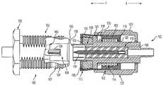
- FIG. 1is a cross-sectional, side view of a connector system 100 according to an embodiment of the invention.
- FIG. 2shows connectors 102 and 150 in a partially mated state.
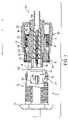
- FIG. 3shows connectors 102 and 150 in a fully mated state.
- FIG. 4is an exploded side view of connector 102 .
- FIGS. 5-7illustrate the process of mating connector 102 with connector 150 .
- FIG. 1is a cross-sectional, side view of a connector system 100 according to an embodiment of the invention.
- Connector system 100includes a first connector 102 (a.k.a., “QC connector 102 ”) and a second connector 104 (a.k.a., “jack connector 150 ”).
- Connector 102is designed to mate with connector 150 .
- FIG. 1shows connectors 102 and 150 in an un-mated configuration.
- jack connector 150comprises a generally cylindrical member 152 that may have external threads 154 , and the distal portion of member 152 defines a cavity 156 . Disposed in cavity 156 may be a contact 158 (e.g., a female contact) for mating with a contact 104 (e.g., a male contact) 104 of QC connector 102 . Preferably, a mating face 160 is formed at the rear end of cavity 156 .
- QC connector 102includes a body 106 having a front mating face 108 .
- body 106defines a cavity in which contact 104 is housed.
- an insulator 110electrically insulates contact 104 from body 106 .
- QC connector 102also includes a generally elongate, ring shaped outer contact or lock ring 112 that surrounds a portion of body 106 .
- the front portion of lock ring 112may include resilient fingers 113 . Resilient fingers 113 tend to flare outwardly as shown in FIG. 1 .
- Part of the body that is surrounded by lock ring 112has an outer diameter that is less than the inner diameter of lock ring 112 .
- a spacebetween an inner surface of lock ring 112 and an outer surface of body 106 .
- a spring 114is disposed within this space and positioned between a shoulder 116 of lock ring 112 and a shoulder 118 of body 106 .
- Body 160may include a retaining step 120 positioned just to the rear of shoulder 116 for limiting the axial movement of lock ring 112 .
- QC connector 102also may include a ring shaped shroud 122 that surrounds a portion of lock ring 112 .
- shroud 122can move relative to body 106 between an open position (shown in FIG. 1 ) and a closed position (see FIG. 3 ).
- shroud 122With shroud 122 disposed in the open position, the user should grip shroud 122 and then, while gripping shroud 122 , exert an axial force (F) on shroud 122 in the direction of connector 150 so that mating face 108 of body 106 enters cavity 156 . As a result of the user exerting force F on shroud, shroud will exert an axial force on lock ring 112 , which force will be in the direction of connector 150 .
- Faxial force
- lock ring 112will exert an axial force on body 106 through spring 114 , which force will be in the direction of connector 150 , and, due to friction, lock ring 112 will exert an axial resistive force on shroud 122 , which resistive force is in a direction opposite of force F and which has a magnitude equal or about equal to force F.
- shroud 122Because body 106 will no longer be able to move in the direction of the axial force applied by the user on shroud 122 , the axial force applied by the user on shroud 122 causes both shroud 122 and lock ring 112 to move in the direction of the force. However, because of the friction between shroud 122 and lock ring 112 , shroud 122 does not appreciably move relative to lock ring 112 .
- lock ring 112will cause spring 114 to compress.
- lock ring 112will not be able to move in the direction of force F.
- the usershould exert in the direction of connector 150 an axial force on shroud 122 where such axial force is greater than the force of friction between shroud 122 and lock ring 112 . This force will cause shroud 122 to move relative to lock ring 122 in the direction of the force (see FIG. 3 ).
- shroud 122When shroud 122 moves relative to lock ring 112 in the direction of the force and into its closed position, shroud 122 exerts an inward force on fingers 113 that forces the fingers to move inward (see FIG. 3 ).
- fingers 113are positioned such that the lip 135 of the fingers 113 are positioned behind a thread or grip ring or other member 167 that projects outwardly from body 152 of connector 150 , thereby locking connectors 150 , 102 together.
- spring 114In this locked position, spring 114 is compressed and therefore exerts a force on shoulder 116 in the direction of arrow X and force on shoulder 118 in the direction of arrow F.
- lips 135are positioned behind (i.e., engaged with) protuberance 167 , the force exerted by spring 114 on shoulder 116 does not cause lock ring 112 to move because the protuberance 167 acts as a stopper, and the force exerted by spring 114 on shoulder 118 urges body 106 in the direction of arrow F so that mating face 108 of connector 102 presses against mating face 160 of connector 150 .
- contact 104is received by contact 158 .
- system 100enables a user to easily mate and un-mate connectors 102 and 150 .
- the userneed only push on shroud 122 in order to lock connectors 102 and 150 together.
- the spring 114maintains a constant force at the mating faces to keep them bottomed, and keeping the mating faces bottomed allows the connectors to have an uninterrupted ground path.
- An uninterrupted ground pathallows the connectors to operate at higher frequencies and have improved electrical characteristics (e.g., VSWR and insertion loss).
- FIGS. 5-7these figures further illustrate the process of mating connector 102 with connector 150 .
- the userneed only pull back on shroud 122 so that shroud 122 moves relative to lock ring 112 and body 106 (i.e., shroud moves from its closed position to its open position).
- shroud 122moves in the direction of arrow X relative to lock ring 112
- the shroud 122no longer exerts the inward force on fingers 113 .
- fingers 113will expand outwardly (i.e., the lips of fingers will not be stopped by stopper 167 ) thereby enabling the user to disengage connector 102 from connector 150 by pulling on shroud 122 .
Landscapes
- Details Of Connecting Devices For Male And Female Coupling (AREA)
Abstract
Description
Claims (18)
Priority Applications (1)
| Application Number | Priority Date | Filing Date | Title |
|---|---|---|---|
| US11/961,623US7513788B2 (en) | 2005-11-04 | 2007-12-20 | Connector and method of mating same with a corresponding connector |
Applications Claiming Priority (3)
| Application Number | Priority Date | Filing Date | Title |
|---|---|---|---|
| US73326105P | 2005-11-04 | 2005-11-04 | |
| US11/590,870US7322846B2 (en) | 2005-11-04 | 2006-11-01 | Quick connect connector |
| US11/961,623US7513788B2 (en) | 2005-11-04 | 2007-12-20 | Connector and method of mating same with a corresponding connector |
Related Parent Applications (1)
| Application Number | Title | Priority Date | Filing Date |
|---|---|---|---|
| US11/590,870ContinuationUS7322846B2 (en) | 2005-11-04 | 2006-11-01 | Quick connect connector |
Publications (2)
| Publication Number | Publication Date |
|---|---|
| US20080096405A1 US20080096405A1 (en) | 2008-04-24 |
| US7513788B2true US7513788B2 (en) | 2009-04-07 |
Family
ID=38004354
Family Applications (2)
| Application Number | Title | Priority Date | Filing Date |
|---|---|---|---|
| US11/590,870ActiveUS7322846B2 (en) | 2005-11-04 | 2006-11-01 | Quick connect connector |
| US11/961,623ActiveUS7513788B2 (en) | 2005-11-04 | 2007-12-20 | Connector and method of mating same with a corresponding connector |
Family Applications Before (1)
| Application Number | Title | Priority Date | Filing Date |
|---|---|---|---|
| US11/590,870ActiveUS7322846B2 (en) | 2005-11-04 | 2006-11-01 | Quick connect connector |
Country Status (1)
| Country | Link |
|---|---|
| US (2) | US7322846B2 (en) |
Cited By (35)
| Publication number | Priority date | Publication date | Assignee | Title |
|---|---|---|---|---|
| US7758370B1 (en)* | 2009-06-26 | 2010-07-20 | Corning Gilbert Inc. | Quick release electrical connector |
| US20110045685A1 (en)* | 2008-05-01 | 2011-02-24 | Katsuhiko Kobayashi | Electrical Connector Assembly |
| US20130072043A1 (en)* | 2011-09-21 | 2013-03-21 | Hon Hai Precision Industry Co.,Ltd. | Testing apparatus for connector |
| US20130196554A1 (en)* | 2010-10-12 | 2013-08-01 | Wolfgang Pfeiffer | Method For Connecting Plug Parts Of An Electrical Plug-In Connector, And Electrical Plug-In Connector |
| US20140004739A1 (en)* | 2009-12-11 | 2014-01-02 | Ppc Broadband, Inc. | Coaxial cable connector sleeve |
| US20140162487A1 (en)* | 2012-11-30 | 2014-06-12 | Bal Seal Engineering, Inc. | Spring connectors with adjustable grooves and related methods |
| US20140308009A1 (en)* | 2013-04-10 | 2014-10-16 | Tyco Electronics Corporation | Connector with locking ring |
| US8888526B2 (en) | 2010-08-10 | 2014-11-18 | Corning Gilbert, Inc. | Coaxial cable connector with radio frequency interference and grounding shield |
| US20150031237A1 (en)* | 2011-10-25 | 2015-01-29 | Perfectvision Manufacturing, Inc. | Coaxial Barrel Fittings and Couplings with Ground Establishing Traveling Sleeves |
| US9048599B2 (en) | 2013-10-28 | 2015-06-02 | Corning Gilbert Inc. | Coaxial cable connector having a gripping member with a notch and disposed inside a shell |
| US9071019B2 (en) | 2010-10-27 | 2015-06-30 | Corning Gilbert, Inc. | Push-on cable connector with a coupler and retention and release mechanism |
| US9136654B2 (en) | 2012-01-05 | 2015-09-15 | Corning Gilbert, Inc. | Quick mount connector for a coaxial cable |
| DE102014103834A1 (en)* | 2014-03-20 | 2015-09-24 | Phoenix Contact Gmbh & Co. Kg | Interference-proof connector |
| US9147963B2 (en) | 2012-11-29 | 2015-09-29 | Corning Gilbert Inc. | Hardline coaxial connector with a locking ferrule |
| US9153911B2 (en) | 2013-02-19 | 2015-10-06 | Corning Gilbert Inc. | Coaxial cable continuity connector |
| US9166348B2 (en) | 2010-04-13 | 2015-10-20 | Corning Gilbert Inc. | Coaxial connector with inhibited ingress and improved grounding |
| US9172154B2 (en) | 2013-03-15 | 2015-10-27 | Corning Gilbert Inc. | Coaxial cable connector with integral RFI protection |
| US9190744B2 (en) | 2011-09-14 | 2015-11-17 | Corning Optical Communications Rf Llc | Coaxial cable connector with radio frequency interference and grounding shield |
| US20160020545A1 (en)* | 2013-04-01 | 2016-01-21 | Yazaki Corporation | Connector |
| US9287659B2 (en) | 2012-10-16 | 2016-03-15 | Corning Optical Communications Rf Llc | Coaxial cable connector with integral RFI protection |
| US9407016B2 (en) | 2012-02-22 | 2016-08-02 | Corning Optical Communications Rf Llc | Coaxial cable connector with integral continuity contacting portion |
| US9525220B1 (en) | 2015-11-25 | 2016-12-20 | Corning Optical Communications LLC | Coaxial cable connector |
| US9548557B2 (en) | 2013-06-26 | 2017-01-17 | Corning Optical Communications LLC | Connector assemblies and methods of manufacture |
| US9548572B2 (en) | 2014-11-03 | 2017-01-17 | Corning Optical Communications LLC | Coaxial cable connector having a coupler and a post with a contacting portion and a shoulder |
| US9590287B2 (en) | 2015-02-20 | 2017-03-07 | Corning Optical Communications Rf Llc | Surge protected coaxial termination |
| US20170162986A1 (en)* | 2015-08-07 | 2017-06-08 | Perfectvision Manufacturing, Inc. | Push-on coaxial connector |
| US9762008B2 (en) | 2013-05-20 | 2017-09-12 | Corning Optical Communications Rf Llc | Coaxial cable connector with integral RFI protection |
| US9859631B2 (en) | 2011-09-15 | 2018-01-02 | Corning Optical Communications Rf Llc | Coaxial cable connector with integral radio frequency interference and grounding shield |
| US10033122B2 (en) | 2015-02-20 | 2018-07-24 | Corning Optical Communications Rf Llc | Cable or conduit connector with jacket retention feature |
| US20190020149A1 (en)* | 2017-07-12 | 2019-01-17 | Commscope Technologies Llc | Quick-Locking Coaxial Connector |
| US10211547B2 (en) | 2015-09-03 | 2019-02-19 | Corning Optical Communications Rf Llc | Coaxial cable connector |
| US10290958B2 (en) | 2013-04-29 | 2019-05-14 | Corning Optical Communications Rf Llc | Coaxial cable connector with integral RFI protection and biasing ring |
| US10756455B2 (en) | 2005-01-25 | 2020-08-25 | Corning Optical Communications Rf Llc | Electrical connector with grounding member |
| US12000514B2 (en) | 2021-06-28 | 2024-06-04 | Microsoft Technology Licensing, Llc | Systems and methods for a floating quick disconnect in liquid cooling |
| US12034264B2 (en) | 2021-03-31 | 2024-07-09 | Corning Optical Communications Rf Llc | Coaxial cable connector assemblies with outer conductor engagement features and methods for using the same |
Families Citing this family (19)
| Publication number | Priority date | Publication date | Assignee | Title |
|---|---|---|---|---|
| JP2008034250A (en)* | 2006-07-28 | 2008-02-14 | Omron Corp | Connector device |
| JP4767923B2 (en)* | 2007-07-27 | 2011-09-07 | タイコエレクトロニクスジャパン合同会社 | Electrical connector and connector assembly |
| DE102007051587A1 (en)* | 2007-10-29 | 2009-04-30 | Robert Bosch Gmbh | Electrical device e.g. ignition coil, attaching device for e.g. valve cover of internal-combustion engine, has electrical device with housing section rotation-asymmetrically formed in such manner that section acts on rest connection |
| GB2475089B (en)* | 2009-11-05 | 2014-09-24 | Connectors Ltd Ab | Connector assembly and a connector part thereof |
| DE202009016090U1 (en) | 2009-11-25 | 2010-03-04 | Rosenberger Hochfrequenztechnik Gmbh & Co. Kg | Easy-to-clean connector |
| US8241060B2 (en)* | 2010-01-05 | 2012-08-14 | Tyco Electronics Corporation | Snap-on coaxial cable connector |
| GB201006061D0 (en)* | 2010-04-12 | 2010-05-26 | Technetix Group Ltd | Cable connector |
| CN102544899A (en)* | 2011-08-29 | 2012-07-04 | 威海乐士康电子有限公司 | Assembled structure of coaxial connector and antenna connector for receiving antenna |
| EP2916396A1 (en)* | 2014-03-06 | 2015-09-09 | PHOENIX CONTACT Connector Technology GmbH | Electrical connector comprising push-pull type latching |
| EP3196987A4 (en)* | 2014-09-19 | 2018-04-25 | Junkosha Inc. | Connector |
| TWM520748U (en)* | 2015-10-16 | 2016-04-21 | T Conn Prec Corp | Circular rapid connector |
| TWI604671B (en)* | 2016-07-14 | 2017-11-01 | 安費諾亮泰企業股份有限公司 | Coupling structure of push lock connector |
| JP6930467B2 (en)* | 2018-03-14 | 2021-09-01 | オムロン株式会社 | connector |
| US10818995B2 (en)* | 2018-11-23 | 2020-10-27 | Keysight Technologies, Inc. | Radio frequency (RF) connection assembly including a pin and bead assembly with a smooth inner edge |
| WO2020112397A1 (en)* | 2018-11-28 | 2020-06-04 | Corning Optical Communications Rf Llc | Locking rf coaxial connector |
| CN214625474U (en) | 2021-03-19 | 2021-11-05 | 泰科电子(上海)有限公司 | Connectors and Connector Components |
| CN115117669B (en)* | 2021-03-19 | 2025-07-04 | 泰科电子(上海)有限公司 | Connectors and Connector Assemblies |
| CN214625501U (en) | 2021-03-19 | 2021-11-05 | 泰科电子(上海)有限公司 | Connector and connector assembly |
| CN115117668A (en) | 2021-03-19 | 2022-09-27 | 泰科电子(上海)有限公司 | Connectors and Connector Components |
Citations (17)
| Publication number | Priority date | Publication date | Assignee | Title |
|---|---|---|---|---|
| US3745514A (en)* | 1971-07-26 | 1973-07-10 | Sealectro Corp | Coaxial connector |
| US3953098A (en)* | 1972-05-30 | 1976-04-27 | Bunker Ramo Corporation | Locking electrical connector |
| US4017139A (en)* | 1976-06-04 | 1977-04-12 | Sealectro Corporation | Positive locking electrical connector |
| US4138181A (en)* | 1978-04-25 | 1979-02-06 | The United States Of America As Represented By The Secretary Of The Navy | Releasable electrical connector |
| US4426127A (en) | 1981-11-23 | 1984-01-17 | Omni Spectra, Inc. | Coaxial connector assembly |
| US4846714A (en)* | 1988-05-16 | 1989-07-11 | Kaman Instrumentation Corporation | Quick disconnect connector |
| US4941846A (en)* | 1989-05-31 | 1990-07-17 | Adams-Russell Electronic Company, Inc. | Quick connect/disconnect microwave connector |
| US5435745A (en)* | 1994-05-31 | 1995-07-25 | Andrew Corporation | Connector for coaxial cable having corrugated outer conductor |
| US5785545A (en)* | 1996-07-02 | 1998-07-28 | The Deutsch Company | Connector for joining two electrical connection assemblies |
| US6394662B1 (en)* | 1999-04-09 | 2002-05-28 | Itt Manufacturing Enterprises, Inc. | Optical fibre connector |
| US6464527B2 (en) | 2000-03-28 | 2002-10-15 | Ez Form Cable Corporation | Quick connect coaxial cable connector |
| US6475014B2 (en)* | 1999-04-28 | 2002-11-05 | Yazaki Corporation | Connector fitting structure |
| US6645011B2 (en) | 2001-08-03 | 2003-11-11 | Radiall | Coaxial connection with locking by snap-fastening |
| US6692286B1 (en) | 1999-10-22 | 2004-02-17 | Huber + Suhner Ag | Coaxial plug connector |
| US6695636B2 (en) | 2002-01-23 | 2004-02-24 | Tyco Electronics Corporation | Lockable electrical connector |
| US6709289B2 (en) | 2002-02-14 | 2004-03-23 | Huber & Suhner Ag | Electrical plug connector |
| US6848931B2 (en)* | 2002-07-19 | 2005-02-01 | Andrew Corporation | Quick attachment SMA connector |
- 2006
- 2006-11-01USUS11/590,870patent/US7322846B2/enactiveActive
- 2007
- 2007-12-20USUS11/961,623patent/US7513788B2/enactiveActive
Patent Citations (18)
| Publication number | Priority date | Publication date | Assignee | Title |
|---|---|---|---|---|
| US3745514A (en)* | 1971-07-26 | 1973-07-10 | Sealectro Corp | Coaxial connector |
| US3953098A (en)* | 1972-05-30 | 1976-04-27 | Bunker Ramo Corporation | Locking electrical connector |
| US4017139A (en)* | 1976-06-04 | 1977-04-12 | Sealectro Corporation | Positive locking electrical connector |
| US4138181A (en)* | 1978-04-25 | 1979-02-06 | The United States Of America As Represented By The Secretary Of The Navy | Releasable electrical connector |
| US4426127A (en) | 1981-11-23 | 1984-01-17 | Omni Spectra, Inc. | Coaxial connector assembly |
| US4846714A (en)* | 1988-05-16 | 1989-07-11 | Kaman Instrumentation Corporation | Quick disconnect connector |
| US4941846A (en)* | 1989-05-31 | 1990-07-17 | Adams-Russell Electronic Company, Inc. | Quick connect/disconnect microwave connector |
| US5435745A (en)* | 1994-05-31 | 1995-07-25 | Andrew Corporation | Connector for coaxial cable having corrugated outer conductor |
| US5785545A (en)* | 1996-07-02 | 1998-07-28 | The Deutsch Company | Connector for joining two electrical connection assemblies |
| US6394662B1 (en)* | 1999-04-09 | 2002-05-28 | Itt Manufacturing Enterprises, Inc. | Optical fibre connector |
| US6475014B2 (en)* | 1999-04-28 | 2002-11-05 | Yazaki Corporation | Connector fitting structure |
| US6595793B2 (en)* | 1999-04-28 | 2003-07-22 | Yazaki Corporation | Connector fitting structure |
| US6692286B1 (en) | 1999-10-22 | 2004-02-17 | Huber + Suhner Ag | Coaxial plug connector |
| US6464527B2 (en) | 2000-03-28 | 2002-10-15 | Ez Form Cable Corporation | Quick connect coaxial cable connector |
| US6645011B2 (en) | 2001-08-03 | 2003-11-11 | Radiall | Coaxial connection with locking by snap-fastening |
| US6695636B2 (en) | 2002-01-23 | 2004-02-24 | Tyco Electronics Corporation | Lockable electrical connector |
| US6709289B2 (en) | 2002-02-14 | 2004-03-23 | Huber & Suhner Ag | Electrical plug connector |
| US6848931B2 (en)* | 2002-07-19 | 2005-02-01 | Andrew Corporation | Quick attachment SMA connector |
Non-Patent Citations (1)
| Title |
|---|
| Winchester Electronics, New Product Announcement, "Quick Connect SMA(TM) Connectors", Oct. 2005, two pages. |
Cited By (66)
| Publication number | Priority date | Publication date | Assignee | Title |
|---|---|---|---|---|
| US10756455B2 (en) | 2005-01-25 | 2020-08-25 | Corning Optical Communications Rf Llc | Electrical connector with grounding member |
| US20110045685A1 (en)* | 2008-05-01 | 2011-02-24 | Katsuhiko Kobayashi | Electrical Connector Assembly |
| US8123544B2 (en)* | 2008-05-01 | 2012-02-28 | Tyco Electronics Japan G.K. | Electrical connector assembly adapted to withstand rotational movement |
| US7758370B1 (en)* | 2009-06-26 | 2010-07-20 | Corning Gilbert Inc. | Quick release electrical connector |
| US9793622B2 (en) | 2009-12-11 | 2017-10-17 | Ppc Broadband, Inc. | Coaxial cable connector sleeve |
| US10446949B2 (en) | 2009-12-11 | 2019-10-15 | Ppc Broadband, Inc. | Coaxial cable connector sleeve |
| US20140004739A1 (en)* | 2009-12-11 | 2014-01-02 | Ppc Broadband, Inc. | Coaxial cable connector sleeve |
| US9124046B2 (en)* | 2009-12-11 | 2015-09-01 | Ppc Broadband | Coaxial cable connector sleeve |
| US9166348B2 (en) | 2010-04-13 | 2015-10-20 | Corning Gilbert Inc. | Coaxial connector with inhibited ingress and improved grounding |
| US9905959B2 (en) | 2010-04-13 | 2018-02-27 | Corning Optical Communication RF LLC | Coaxial connector with inhibited ingress and improved grounding |
| US10312629B2 (en) | 2010-04-13 | 2019-06-04 | Corning Optical Communications Rf Llc | Coaxial connector with inhibited ingress and improved grounding |
| US8888526B2 (en) | 2010-08-10 | 2014-11-18 | Corning Gilbert, Inc. | Coaxial cable connector with radio frequency interference and grounding shield |
| US20130196554A1 (en)* | 2010-10-12 | 2013-08-01 | Wolfgang Pfeiffer | Method For Connecting Plug Parts Of An Electrical Plug-In Connector, And Electrical Plug-In Connector |
| US8944839B2 (en)* | 2010-10-12 | 2015-02-03 | Intercontec Pfeiffer Gmbh | Method for connecting plug parts of an electrical plug-in connector, and electrical plug-in connector |
| US9071019B2 (en) | 2010-10-27 | 2015-06-30 | Corning Gilbert, Inc. | Push-on cable connector with a coupler and retention and release mechanism |
| US9190744B2 (en) | 2011-09-14 | 2015-11-17 | Corning Optical Communications Rf Llc | Coaxial cable connector with radio frequency interference and grounding shield |
| US9859631B2 (en) | 2011-09-15 | 2018-01-02 | Corning Optical Communications Rf Llc | Coaxial cable connector with integral radio frequency interference and grounding shield |
| US8562380B2 (en)* | 2011-09-21 | 2013-10-22 | Hong Fu Jin Precision Industry (Shenzhen) Co., Ltd. | Testing apparatus having a connecting member movably located between a securing member and a pressing member and having a resisting member on one end and a resilient member on the other end |
| US20130072043A1 (en)* | 2011-09-21 | 2013-03-21 | Hon Hai Precision Industry Co.,Ltd. | Testing apparatus for connector |
| US20150031237A1 (en)* | 2011-10-25 | 2015-01-29 | Perfectvision Manufacturing, Inc. | Coaxial Barrel Fittings and Couplings with Ground Establishing Traveling Sleeves |
| US9490592B2 (en)* | 2011-10-25 | 2016-11-08 | Perfectvision Manufacturing, Inc. | Coaxial barrel fittings and couplings with ground establishing traveling sleeves |
| US9768565B2 (en) | 2012-01-05 | 2017-09-19 | Corning Optical Communications Rf Llc | Quick mount connector for a coaxial cable |
| US9136654B2 (en) | 2012-01-05 | 2015-09-15 | Corning Gilbert, Inc. | Quick mount connector for a coaxial cable |
| US9484645B2 (en) | 2012-01-05 | 2016-11-01 | Corning Optical Communications Rf Llc | Quick mount connector for a coaxial cable |
| US9407016B2 (en) | 2012-02-22 | 2016-08-02 | Corning Optical Communications Rf Llc | Coaxial cable connector with integral continuity contacting portion |
| US9912105B2 (en) | 2012-10-16 | 2018-03-06 | Corning Optical Communications Rf Llc | Coaxial cable connector with integral RFI protection |
| US9287659B2 (en) | 2012-10-16 | 2016-03-15 | Corning Optical Communications Rf Llc | Coaxial cable connector with integral RFI protection |
| US10236636B2 (en) | 2012-10-16 | 2019-03-19 | Corning Optical Communications Rf Llc | Coaxial cable connector with integral RFI protection |
| US9722363B2 (en) | 2012-10-16 | 2017-08-01 | Corning Optical Communications Rf Llc | Coaxial cable connector with integral RFI protection |
| US9147963B2 (en) | 2012-11-29 | 2015-09-29 | Corning Gilbert Inc. | Hardline coaxial connector with a locking ferrule |
| US10447000B2 (en) | 2012-11-30 | 2019-10-15 | Bal Seal Engineering, Inc. | Spring connectors with adjustable grooves and related methods |
| US20140162487A1 (en)* | 2012-11-30 | 2014-06-12 | Bal Seal Engineering, Inc. | Spring connectors with adjustable grooves and related methods |
| US9882332B2 (en)* | 2012-11-30 | 2018-01-30 | Bal Seal Engineering, Inc. | Spring connectors with adjustable grooves and related methods |
| US9153911B2 (en) | 2013-02-19 | 2015-10-06 | Corning Gilbert Inc. | Coaxial cable continuity connector |
| US9172154B2 (en) | 2013-03-15 | 2015-10-27 | Corning Gilbert Inc. | Coaxial cable connector with integral RFI protection |
| US20160020545A1 (en)* | 2013-04-01 | 2016-01-21 | Yazaki Corporation | Connector |
| US9960520B2 (en)* | 2013-04-01 | 2018-05-01 | Yazaki Corporation | Connector having connector constituents and a locked portion |
| US8944838B2 (en)* | 2013-04-10 | 2015-02-03 | Tyco Electronics Corporation | Connector with locking ring |
| US20140308009A1 (en)* | 2013-04-10 | 2014-10-16 | Tyco Electronics Corporation | Connector with locking ring |
| US10290958B2 (en) | 2013-04-29 | 2019-05-14 | Corning Optical Communications Rf Llc | Coaxial cable connector with integral RFI protection and biasing ring |
| US9762008B2 (en) | 2013-05-20 | 2017-09-12 | Corning Optical Communications Rf Llc | Coaxial cable connector with integral RFI protection |
| US10396508B2 (en) | 2013-05-20 | 2019-08-27 | Corning Optical Communications Rf Llc | Coaxial cable connector with integral RFI protection |
| US9548557B2 (en) | 2013-06-26 | 2017-01-17 | Corning Optical Communications LLC | Connector assemblies and methods of manufacture |
| US9048599B2 (en) | 2013-10-28 | 2015-06-02 | Corning Gilbert Inc. | Coaxial cable connector having a gripping member with a notch and disposed inside a shell |
| DE102014103834A1 (en)* | 2014-03-20 | 2015-09-24 | Phoenix Contact Gmbh & Co. Kg | Interference-proof connector |
| DE102014103834B4 (en)* | 2014-03-20 | 2018-07-05 | Phoenix Contact Gmbh & Co. Kg | Interference-proof connector |
| US9548572B2 (en) | 2014-11-03 | 2017-01-17 | Corning Optical Communications LLC | Coaxial cable connector having a coupler and a post with a contacting portion and a shoulder |
| US9991651B2 (en) | 2014-11-03 | 2018-06-05 | Corning Optical Communications Rf Llc | Coaxial cable connector with post including radially expanding tabs |
| US9590287B2 (en) | 2015-02-20 | 2017-03-07 | Corning Optical Communications Rf Llc | Surge protected coaxial termination |
| US10033122B2 (en) | 2015-02-20 | 2018-07-24 | Corning Optical Communications Rf Llc | Cable or conduit connector with jacket retention feature |
| US9735520B2 (en)* | 2015-08-07 | 2017-08-15 | Perfectvision Manufacturing, Inc. | Push-on coaxial connector |
| US10069256B2 (en) | 2015-08-07 | 2018-09-04 | Perfectvision Manufacturing, Inc. | Push-on coaxial connector |
| US10193282B2 (en) | 2015-08-07 | 2019-01-29 | Perfectvision Manufacturing, Inc. | Push-on coaxial connector |
| US9905979B2 (en) | 2015-08-07 | 2018-02-27 | Perfectvision Manufacturing, Inc. | Push-on coaxial connector |
| US10361521B2 (en) | 2015-08-07 | 2019-07-23 | Perfectvision Manufacturing, Inc. | Push-on coaxial connector |
| US20170162986A1 (en)* | 2015-08-07 | 2017-06-08 | Perfectvision Manufacturing, Inc. | Push-on coaxial connector |
| US10855035B2 (en) | 2015-08-07 | 2020-12-01 | Perfectvision Manufacturing, Inc. | Push-on coaxial connector |
| US10211547B2 (en) | 2015-09-03 | 2019-02-19 | Corning Optical Communications Rf Llc | Coaxial cable connector |
| US9525220B1 (en) | 2015-11-25 | 2016-12-20 | Corning Optical Communications LLC | Coaxial cable connector |
| US9882320B2 (en) | 2015-11-25 | 2018-01-30 | Corning Optical Communications Rf Llc | Coaxial cable connector |
| US10651593B2 (en)* | 2017-07-12 | 2020-05-12 | Commscope Technologies Llc | Quick-locking coaxial connector |
| US20200266579A1 (en)* | 2017-07-12 | 2020-08-20 | Commscope Technologies Llc | Quick-locking coaxial connector |
| US20190020149A1 (en)* | 2017-07-12 | 2019-01-17 | Commscope Technologies Llc | Quick-Locking Coaxial Connector |
| US11177611B2 (en)* | 2017-07-12 | 2021-11-16 | Commscope Technologies Llc | Method of mating a quick-locking coaxial connector |
| US12034264B2 (en) | 2021-03-31 | 2024-07-09 | Corning Optical Communications Rf Llc | Coaxial cable connector assemblies with outer conductor engagement features and methods for using the same |
| US12000514B2 (en) | 2021-06-28 | 2024-06-04 | Microsoft Technology Licensing, Llc | Systems and methods for a floating quick disconnect in liquid cooling |
Also Published As
| Publication number | Publication date |
|---|---|
| US20070105417A1 (en) | 2007-05-10 |
| US7322846B2 (en) | 2008-01-29 |
| US20080096405A1 (en) | 2008-04-24 |
Similar Documents
| Publication | Publication Date | Title |
|---|---|---|
| US7513788B2 (en) | Connector and method of mating same with a corresponding connector | |
| US7189097B2 (en) | Snap lock connector | |
| US7568934B1 (en) | Electrical connector having a sealing mechanism | |
| US7335058B1 (en) | Snap-fit connector assembly | |
| CN102709744B (en) | Connector having locking mechanism | |
| US7972158B2 (en) | Co-axial push-pull plug-in connector | |
| US8221161B2 (en) | Break-away adapter | |
| US8241060B2 (en) | Snap-on coaxial cable connector | |
| US7322859B2 (en) | Electrical connector | |
| US6361348B1 (en) | Right angle, snap on coaxial electrical connector | |
| CN108011264B (en) | Quick-lock coaxial connector and connector combination | |
| US10141688B2 (en) | Plug connector with resilient engagement element and seal | |
| EP1455420A1 (en) | Electrical connector with a locking ring, especially a coaxial plug | |
| US5167520A (en) | Cup fit plug connector | |
| US10355406B2 (en) | Electrical connector | |
| JP3127287B2 (en) | Coaxial connector device | |
| TWI237929B (en) | Connector | |
| US6511339B1 (en) | Cable connector assembly with push lock | |
| US8435061B2 (en) | Connector | |
| CN214013189U (en) | Push-pull joint type coaxial connector | |
| KR102168423B1 (en) | Coaxial connector | |
| CN111048961A (en) | Connecting plug | |
| JPS5933181Y2 (en) | connector connection mechanism | |
| JPS6035181Y2 (en) | electrical connectors | |
| JP2000164296A (en) | connector |
Legal Events
| Date | Code | Title | Description |
|---|---|---|---|
| STCF | Information on status: patent grant | Free format text:PATENTED CASE | |
| AS | Assignment | Owner name:MADISON CAPITAL FUNDING LLC, AS AGENT, ILLINOIS Free format text:SECURITY AGREEMENT;ASSIGNOR:WINCHESTER ELECTRONICS CORPORATION;REEL/FRAME:028634/0754 Effective date:20120725 | |
| FPAY | Fee payment | Year of fee payment:4 | |
| AS | Assignment | Owner name:CIT FINANCE LLC, NEW YORK Free format text:SECURITY INTEREST;ASSIGNORS:WINCHESTER ELECTRONICS CORPORATION;CLEMENTS NATIONAL COMPANY;TRU CORPORATION;AND OTHERS;REEL/FRAME:034280/0547 Effective date:20141117 | |
| AS | Assignment | Owner name:WINCHESTER ELECTRONICS CORPORATION, CONNECTICUT Free format text:RELEASE BY SECURED PARTY;ASSIGNOR:MADISON CAPITAL FUNDING LLC;REEL/FRAME:034201/0812 Effective date:20141117 | |
| AS | Assignment | Owner name:WINCHESTER ELECTRONICS CORPORATION, CONNECTICUT Free format text:RELEASE BY SECURED PARTY;ASSIGNOR:MADISON CAPITAL FUNDING LLC;REEL/FRAME:034210/0469 Effective date:20141117 | |
| AS | Assignment | Owner name:WILMINGTON TRUST, NATIONAL ASSOCIATION, AS COLLATE Free format text:SECOND LIEN SECURITY AGREEMENT;ASSIGNORS:WINCHESTER ELECTRONICS CORPORATION;TRU CORPORATION;SRI HERMETICS LLC;AND OTHERS;REEL/FRAME:034306/0792 Effective date:20141117 | |
| AS | Assignment | Owner name:ANTARES CAPITAL LP, AS ADMINISTRATIVE AGENT, ILLIN Free format text:SECURITY INTEREST;ASSIGNORS:CLEMENTS NATIONAL COMPANY;SRI HERMETICS, LLC;TRU CORPORATION;AND OTHERS;REEL/FRAME:039218/0344 Effective date:20160630 | |
| AS | Assignment | Owner name:CLEMENTS NATIONAL COMPANY, CONNECTICUT Free format text:RELEASE BY SECURED PARTY;ASSIGNOR:WILMINGTON TRUST, NATIONAL ASSOCIATION;REEL/FRAME:039234/0013 Effective date:20160630 Owner name:WINCHESTER ELECTRONICS CORPORATION, CONNECTICUT Free format text:RELEASE BY SECURED PARTY;ASSIGNOR:WILMINGTON TRUST, NATIONAL ASSOCIATION;REEL/FRAME:039234/0013 Effective date:20160630 Owner name:TRU CORPORATION, CONNECTICUT Free format text:RELEASE BY SECURED PARTY;ASSIGNOR:WILMINGTON TRUST, NATIONAL ASSOCIATION;REEL/FRAME:039234/0013 Effective date:20160630 Owner name:SRI HERMETICS, LLC, CONNECTICUT Free format text:RELEASE BY SECURED PARTY;ASSIGNOR:WILMINGTON TRUST, NATIONAL ASSOCIATION;REEL/FRAME:039234/0013 Effective date:20160630 | |
| AS | Assignment | Owner name:TRU CORPORATION, CONNECTICUT Free format text:RELEASE BY SECURED PARTY;ASSIGNOR:CIT FINANCE LLC;REEL/FRAME:039379/0882 Effective date:20160630 Owner name:WINCHESTER ELECTRONICS CORPORATION, CONNECTICUT Free format text:RELEASE BY SECURED PARTY;ASSIGNOR:CIT FINANCE LLC;REEL/FRAME:039379/0882 Effective date:20160630 Owner name:CLEMENTS NATIONAL COMPANY, CONNECTICUT Free format text:RELEASE BY SECURED PARTY;ASSIGNOR:CIT FINANCE LLC;REEL/FRAME:039379/0882 Effective date:20160630 Owner name:SRI HERMETICS, LLC, CONNECTICUT Free format text:RELEASE BY SECURED PARTY;ASSIGNOR:CIT FINANCE LLC;REEL/FRAME:039379/0882 Effective date:20160630 | |
| FPAY | Fee payment | Year of fee payment:8 | |
| AS | Assignment | Owner name:WINCHESTER INTERCONNECT CORPORATION, DELAWARE Free format text:CHANGE OF NAME;ASSIGNOR:WINCHESTER ELECTRONICS CORPORATION;REEL/FRAME:046214/0895 Effective date:20171130 | |
| AS | Assignment | Owner name:CLEMENTS NATIONAL COMPANY, CONNECTICUT Free format text:RELEASE BY SECURED PARTY;ASSIGNOR:ANTARES CAPITAL LP, AS COLLATERAL AGENT;REEL/FRAME:047878/0322 Effective date:20181024 Owner name:SRI HERMETICS, LLC, CONNECTICUT Free format text:RELEASE BY SECURED PARTY;ASSIGNOR:ANTARES CAPITAL LP, AS COLLATERAL AGENT;REEL/FRAME:047878/0322 Effective date:20181024 Owner name:WINCHESTER ELECTRONICS CORPORATION, CONNECTICUT Free format text:RELEASE BY SECURED PARTY;ASSIGNOR:ANTARES CAPITAL LP, AS COLLATERAL AGENT;REEL/FRAME:047878/0322 Effective date:20181024 Owner name:TRU CORPORATION, CONNECTICUT Free format text:RELEASE BY SECURED PARTY;ASSIGNOR:ANTARES CAPITAL LP, AS COLLATERAL AGENT;REEL/FRAME:047878/0322 Effective date:20181024 | |
| MAFP | Maintenance fee payment | Free format text:PAYMENT OF MAINTENANCE FEE, 12TH YEAR, LARGE ENTITY (ORIGINAL EVENT CODE: M1553); ENTITY STATUS OF PATENT OWNER: LARGE ENTITY Year of fee payment:12 |