US7513665B2 - Headlamp module and headlamp assembly with internally reflecting translucent member - Google Patents
Headlamp module and headlamp assembly with internally reflecting translucent memberDownload PDFInfo
- Publication number
- US7513665B2 US7513665B2US11/435,249US43524906AUS7513665B2US 7513665 B2US7513665 B2US 7513665B2US 43524906 AUS43524906 AUS 43524906AUS 7513665 B2US7513665 B2US 7513665B2
- Authority
- US
- United States
- Prior art keywords
- headlamp
- light
- light source
- translucent member
- module
- Prior art date
- Legal status (The legal status is an assumption and is not a legal conclusion. Google has not performed a legal analysis and makes no representation as to the accuracy of the status listed.)
- Expired - Fee Related
Links
Images


Classifications
- F—MECHANICAL ENGINEERING; LIGHTING; HEATING; WEAPONS; BLASTING
- F21—LIGHTING
- F21S—NON-PORTABLE LIGHTING DEVICES; SYSTEMS THEREOF; VEHICLE LIGHTING DEVICES SPECIALLY ADAPTED FOR VEHICLE EXTERIORS
- F21S41/00—Illuminating devices specially adapted for vehicle exteriors, e.g. headlamps
- F21S41/30—Illuminating devices specially adapted for vehicle exteriors, e.g. headlamps characterised by reflectors
- F21S41/32—Optical layout thereof
- F21S41/322—Optical layout thereof the reflector using total internal reflection
- F—MECHANICAL ENGINEERING; LIGHTING; HEATING; WEAPONS; BLASTING
- F21—LIGHTING
- F21S—NON-PORTABLE LIGHTING DEVICES; SYSTEMS THEREOF; VEHICLE LIGHTING DEVICES SPECIALLY ADAPTED FOR VEHICLE EXTERIORS
- F21S41/00—Illuminating devices specially adapted for vehicle exteriors, e.g. headlamps
- F21S41/10—Illuminating devices specially adapted for vehicle exteriors, e.g. headlamps characterised by the light source
- F21S41/14—Illuminating devices specially adapted for vehicle exteriors, e.g. headlamps characterised by the light source characterised by the type of light source
- F21S41/141—Light emitting diodes [LED]
- F21S41/147—Light emitting diodes [LED] the main emission direction of the LED being angled to the optical axis of the illuminating device
- F21S41/148—Light emitting diodes [LED] the main emission direction of the LED being angled to the optical axis of the illuminating device the main emission direction of the LED being perpendicular to the optical axis
- F—MECHANICAL ENGINEERING; LIGHTING; HEATING; WEAPONS; BLASTING
- F21—LIGHTING
- F21S—NON-PORTABLE LIGHTING DEVICES; SYSTEMS THEREOF; VEHICLE LIGHTING DEVICES SPECIALLY ADAPTED FOR VEHICLE EXTERIORS
- F21S41/00—Illuminating devices specially adapted for vehicle exteriors, e.g. headlamps
- F21S41/10—Illuminating devices specially adapted for vehicle exteriors, e.g. headlamps characterised by the light source
- F21S41/14—Illuminating devices specially adapted for vehicle exteriors, e.g. headlamps characterised by the light source characterised by the type of light source
- F21S41/141—Light emitting diodes [LED]
- F21S41/151—Light emitting diodes [LED] arranged in one or more lines
- F—MECHANICAL ENGINEERING; LIGHTING; HEATING; WEAPONS; BLASTING
- F21—LIGHTING
- F21Y—INDEXING SCHEME ASSOCIATED WITH SUBCLASSES F21K, F21L, F21S and F21V, RELATING TO THE FORM OR THE KIND OF THE LIGHT SOURCES OR OF THE COLOUR OF THE LIGHT EMITTED
- F21Y2115/00—Light-generating elements of semiconductor light sources
- F21Y2115/10—Light-emitting diodes [LED]
Definitions
- the inventionrelates generally to a headlamp assembly and a headlamp module for use in a motor vehicle. More specifically, the invention relates to a headlamp module having an internally-reflecting trough for directing light rays in a forward direction and a headlamp assembly having a plurality of headlamp modules, at least one of which includes an internally-reflecting trough for directing light rays in a forward direction.
- Conventional headlamp assembliestypically include one or more sets of headlamp modules cooperating with each other to provide illumination for a motor vehicle.
- one set of headlamp modulesmay define a low beam
- another set of headlamp modulesmay define a high beam
- another set of headlamp modulesmay define a turn signal.
- Each of the headlamp modulestypically includes a housing and a lens cooperating to define a cavity, a light element that is generally centrally located within the cavity, and a reflector positioned near a rear portion of the cavity to reflect light rays from the light element towards the front of the cavity and out through the lens.
- the light elementis a light emitting diode connected to the headlamp module by a support arm.
- the reflectoris typically a component made of a generally reflective material, such as polished metal or highly-reflective plastic that covers all or most of the rear wall of the cavity.
- the housing and the components defining and providing electricity to the light elementare potentially exposed to undesirable heat levels from light element. Therefore, this type of design typically requires temperature mitigating components, such as a heatsink supporting the light element with respect to the housing and cooling channels formed by the housing itself. Even if these structures are able to consistently prevent undesirably high heat levels, the temperature mitigating components generally increase the complexity and the part cost of this type of headlamp module.
- the light element, the components supporting the light element, and the reflectorare all highly visible components. More specifically, these components are particularly visible when the light element is not emitting light, causing the unlit headlamp module to have a generally undesirable aesthetic appearance.
- a headlamp moduleis an internal reflector module.
- a light sourceis spaced apart from the base of a translucent block for directing light rays into the body of the translucent block. More specifically, the light source is positioned along a central axis of the translucent block so that the light rays exit the light source, travel across an air gap, and then enter the translucent block. The light rays are then reflected internally by the inner surfaces of the translucent block in a desired direction.
- the centralized location of the light sourcecreates a generally aesthetically undesirable appearance.
- the air gapmay cause undesirable light loss or an unsecured connection between the light source and the translucent block.
- a headlamp moduleincluding a light source for emitting light rays and a translucent member for supporting the light source and directing the light rays in a forward direction. More specifically, the light element is positioned so that the light rays enter the translucent member and are internally reflected in a forward direction by a reflection surface. The light rays then pass through an exit surface of the translucent member as a light beam.
- the support portionis positioned with respect to the exit surface such that a projection of the support portion along a line parallel to the light ray axis is located adjacent to or outside of a periphery of the exit surface. Therefore, the light source is discretely positioned with respect to the exit surface so as to be substantially hidden to an observer examining the unlit headlamp module from the front of the vehicle.
- the translucent memberincludes top and bottom surfaces that each intersect respective portions of the exit surface and the support portion is defined by the top surface. More specifically, the top surface extends generally perpendicularly from a top portion of the exit surface and defines a relief for supporting the light element.
- the bottom surfaceextends in a direction that is not perpendicular with the exit surface so that the light rays are focused into a beam exiting the exit surface. More specifically, the bottom surface generally defines a parabola and the light source is positioned adjacent to a focus thereof so that the light rays are vertically focused into a beam.
- the headlamp modulealso includes first and second side surfaces that intersect: the top surface, the bottom surface, and the exit surface.
- the side surfaceseach preferably include a tapered portion extending in a direction not parallel to the light ray axis so that the light rays are horizontally focused into a beam exiting the exit surface.
- the tapered portionmay be generally linear or arcuate.
- the translucent memberincludes a reflective coating defining at least a portion of the reflection surface to prevent light rays from exiting the translucent member through surfaces other than the exit surface.
- the headlamp moduleincludes a plurality of light sources supported by a second support portion of the translucent member.
- the light sourceemits light rays through an outer surface and at least a portion of the outer surface is engaged by a support portion of the translucent member so that light rays emitted through the outer surface of the light source are able to immediately enter the translucent member.
- This configurationreduces light losses that may occur when the light rays from traveling through different mediums.
- the light sourceis a light emitting diode and the outer surface is at least partially defined by a translucent protective coating. Additionally, the support portion preferably completely engages the outer surface of the translucent protective coating. Furthermore, the translucent protective coating is preferably connected to the support portion by a form-fitting engagement.
- a headlamp assembly for a motor vehicleincludes a plurality of headlamp modules cooperating to provide illumination for the motor vehicle.
- at least one of the plurality of headlamp modulesis a trough module cooperating with at least one other trough module to define a set of trough modules.
- the headlamp assemblymay also include a set of projector modules cooperating with the set of trough modules to generate a low beam.
- the headlamp assemblymay also include a high beam module configured to generate a high beam and a turn signal module configured to generate a light signal beam.
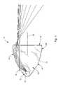
- FIG. 1is an isometric view of a headlamp assembly connected to a motor vehicle and embodying the principles of the present invention, wherein the headlamp assembly includes a set of trough-type headlamp modules and a set of projector-type headlamp modules;
- FIG. 2is an isometric view of a trough-type headlamp module shown in FIG. 1 having a light source and a translucent member and embodying the principles of the present invention
- FIG. 3is a cross-sectional view of the trough-type headlamp module taken along line 2 - 2 in FIG. 2 ;
- FIG. 4is a front view of the trough-type headlamp module shown in FIG. 2 ;
- FIG. 5is a top view of the trough-type headlamp module shown in FIG. 2 ;
- FIG. 6is a top view of an alternative embodiment of a trough-type headlamp module having tapered side walls and embodying the principles of the present invention
- FIG. 7is an isometric view of another alternative embodiment of a trough-type headlamp module having multiple light elements and embodying the principles of the present invention.
- FIG. 8is a cross-sectional view similar to FIG. 3 of yet another alternative embodiment of a trough-type headlamp module having a light source with a limited spread and embodying the principles of the present invention.
- FIG. 9is a cross-sectional view similar to FIG. 3 of another alternative embodiment of a trough-type headlamp module having a reflective coating on a portion of the translucent member and embodying the principles of the present invention.
- FIG. 1shows a headlamp assembly 2 installed in the front of a motor vehicle 3 , including a set of trough-type headlamp modules 10 and a set of projector-type headlamp modules 5 cooperating to generate a low beam; a high beam module 6 for generating a high beam; a set of turn signal modules 7 a, 7 b for generating a turn signal beam; and a set of park light modules 8 for generating a parking light beam.
- the projector-type headlamp modules 5 , the high beam module 6 , the turn signal modules 7 a, 7 b, and the park light modules 8 shown in FIG. 1are each generally known in the prior art.
- FIG. 2shows an enlarged view of the trough-type headlamp module 10 shown in FIG. 1 .
- the trough-type headlamp module 10includes a light source, such as a light emitting diode (LED) 12 , and a translucent member, such as a trough 14 , for directing light rays from the LED 12 in a forward direction. More specifically, the LED 12 is positioned near a rear portion 15 of the trough 14 so that light rays enter the trough 14 and are directed forwards through an exit surface 16 at a front portion 17 of the trough 14 to define a light beam for illuminating an area in front of the motor vehicle.
- a light sourcesuch as a light emitting diode (LED) 12
- a translucent membersuch as a trough 14
- the LED 12includes a chip 18 for emitting light, a translucent protective coating 20 surrounding the chip 18 for protection thereof, and a substrate 22 supporting the chip 18 within the trough 14 and housing electrical components of the LED 12 .
- a translucent protective coating 20surrounding the chip 18 for protection thereof
- a substrate 22supporting the chip 18 within the trough 14 and housing electrical components of the LED 12 .
- an electrical currentis passed to the chip 18 via electrical wiring (not shown) and the movement of electrons across a pair of diodes (not shown) causes the LED 12 to emit light rays 30 .
- any other appropriate light sourcemay be used with the trough-type headlamp module 10 , including but not limited to incandescent light bulbs or high intensity discharge lamp.
- the trough 14 shown in the figuresis a single, unitary solid body component defining a top surface 32 , a pair of side surfaces 34 , 36 , and a bottom surface 38 that each intersect the exit surface 16 along edges thereof. More specifically, the top surface 32 and the exit surface 16 are both generally planar surfaces positioned generally perpendicular to each other (see FIG. 3 ). Furthermore, the side surfaces 34 , 36 and the bottom surface 38 each define generally arcuate surfaces for directing the light rays as desired, as will be discussed in further detail below.
- the side surfaces 34 , 36are generally perpendicular to the exit surface 16 at the point of intersection, but taper inwardly along respective parabolic paths 40 , 42 from the front portion 17 to the back portion 15 of the trough 14 (see FIG. 5 ).
- the bottom surface 38defines a parabolic path 44 tapered upwardly from the front portion 17 to the back portion 15 of the trough 14 (see FIG. 3 ).
- the parabolic paths 40 , 42 , 44 of the side and bottom surfaces 34 , 36 , 38cause light rays to be directed light towards the center of the beam pattern that exits through the exit surface 16 .
- the LED 12is supported by a support portion 46 of the trough 14 positioned with respect to the exit surface 16 such that a projection of the support portion 46 along a line 60 parallel to the light ray axis 48 , is located adjacent to or outside of a periphery 62 of the exit surface 16 , thereby substantially hiding the LED 12 to an observer examining the unlit trough-type headlamp module 10 from the front of the vehicle.
- This configurationis illustrated in FIGS. 2 and 4 , where the support portion 46 is positioned in-line with the periphery 62 of the exit surface 16 .
- the support portion 46 in the figuresis a recess formed in the top surface 32 of the trough 14 so that the light rays entering the trough 14 are directed towards the bottom surface 38 (as best shown in FIG. 3 ). More specifically, the support portion 46 is located in the rear portion 15 of the trough 14 , adjacent to a focus 56 of the parabolic paths 40 , 42 , 44 of the side and bottom surfaces 34 , 36 , 38 .
- the positioning of the LED 12 adjacent to the focus 56 of the parabolic paths 40 , 42 , 44causes the light rays that exit the LED to be focused into a beam that exits the exit surface 16 .
- the positioning of the LED 12 along the top surface 32 of the troughimproves the aesthetic appearance by minimizing the perception of the LED 12 , of the trough-type headlamp module 10 for an observer viewing the module 10 from the front of the vehicle.
- the orientation of the LED 12 shining light rays in the downward directionminimizes glare to occupants of on-coming vehicles.
- the support portion 46 shown in the figuresconforms to the shape of the LED 12 to minimize or eliminate any air gaps between the LED outer surface and the trough 14 .
- the form-fitting configuration between the outer surface of the LED 12 and the trough 14securely connects the components 12 , 14 to each other and reduces the likelihood of undesirable separation thereof. Furthermore, the form-fitting configuration reduces or prevents relative movement between the components 12 , 14 , thereby reducing premature part wear.
- the LED 12may be coupled with the trough 14 by a form-fitting engagement or by another appropriate connection means, such as an adhesive or a mechanical fastener. However, direct contact between the LED chip 18 and the trough 14 may cause damage or premature wear to the LED 12 . Therefore, the translucent protective coating 20 surrounds the chip 18 to provide protection and to increase the product life of the LED 12 .
- the elimination of air gaps between the LED outer surface and the trough 14may also reduce light losses within the trough-type headlamp module 10 . It is a natural principle that light traveling between different mediums may undergo light losses due to reflection. Thus, it is generally desirable to minimize the number of different mediums that the light rays must travel through before exiting the trough-type headlamp module 10 . It is therefore more specifically desirable to minimize air gaps that the light rays must travel through.
- the light rays 30 entering the trough 14are directed towards the bottom surface 38 and substantially internally reflected in a forward direction towards the exit surface 16 . More specifically, some of the light rays (the reflected rays 30 a ) are reflected towards the exit surface 16 while the remaining light rays (the refracted rays 30 b ) may exit the trough 14 through the bottom surface 38 .
- resultant light raystypically include both reflected components and refracted components. However, for illustrative purposes, resultant light rays are referenced by and depicted with their dominant components.
- the term “reflected rays 30 a ”refers to rays each have a higher percentage of light that is reflected towards the exit surface 16 than light that is refracted through the bottom surface 38 of the trough 14 .
- the term “refracted rays 30 b ”refers to rays each have a higher percentage of light that is refracted as it exits the bottom surface 38 than light that is reflected towards the exit surface 16 .
- the reflected rays 30 aeach strike the bottom surface 38 at a relatively large angle of incidence 50 and the refracted rays 30 b each strike the bottom surface 38 at a relatively small angle of incidence 50 .
- the reflected rays 30 aare each substantially completely reflected towards the exit surface 16 whereas the refracted rays 30 b are each permitted to substantially completely exit the trough 14 through the bottom surface 38 .
- the refracted rays 30 bare not utilized for illuminating the area in front of the vehicle. Therefore, it is desirable to maximize the reflected rays 30 a and minimize the refracted rays 30 b, as will be discussed in more detail below with respect to further embodiments of the present invention.
- the bottom surface 38 of the trough 14defines a parabolic path 44 . More specifically, the parabolic path 44 is configured such that the reflected rays 30 a are generally evenly spread in a vertical direction when shining through the exit surface 16 . The positioning of the LED 12 adjacent to the focus 56 of the parabolic path 44 of the bottom surface 38 further improves the concentration of the reflected rays 30 a in the vertical direction.
- the light rays 30only exit a lower portion 54 of the exit surface 16 , thereby only illuminating a lower portion of the trough-type headlamp module 10 .
- the illuminated portion 54is defined as the portion of the exit surface 16 that receives a substantial amount of light rays when the LED is illuminated.
- a non-illuminated portion 58is defined as the portion of the exit surface 16 that receives little or no light when the LED is illuminated. Although the non-illuminated portion 58 may receive trace amounts of light that are remnants of the refracted rays 30 b, this light is not necessarily sufficient enough to effectively illuminate an area in front of the trough-type headlamp module 10 .
- the parabolic path 44is also configured such that the rays 30 a reflected by the bottom surface 38 are directed so as to be parallel with each other and to define a light beam extending generally along a light ray axis 48 . Although some of the reflected rays 30 a may extend in a direction not parallel to the axis 48 , the headlamp beam is substantially focused to extend along the axis 48 .
- the side surfaces 34 , 36 of the trough 14also define parabolic paths 40 , 42 . More specifically, the parabolic paths 40 , 42 are configured such that the reflected rays 30 a are generally evenly spread in a horizontal direction when shining or passing through the exit surface 16 (as best shown in FIG. 5 ). The positioning of the LED 12 adjacent to the focus 56 of the parabolic paths 40 , 42 further improves the concentration of the reflected rays 30 a in the horizontal direction.
- the parabolic paths 40 , 42are configured such that only some of the reflected rays 30 a that are reflected by the side surfaces 34 , 36 are directed so as to be parallel with each other and to define the headlamp beam extending along a light ray axis 48 .
- the remaining reflected rays 30 aare directed along paths not parallel with the light ray axis 48 so as to be dispersed across lateral areas in front of the vehicle. More specifically, while it is generally desirable for the headlamp beam to have a relatively focused spread in the vertical direction, it is generally desirable for the headlamp beam to have a wider range of lateral illumination so that the vehicle occupants are able to see a wider area in front of the vehicle.
- the path 44 of the bottom surface 38maintains a generally downward slope near the front portion 17 of the trough 14
- the side surfaces 34 , 36have paths 40 , 42 that are generally parallel with the beam axis 48 near the front portion 17 of the trough 14 .
- the respective paths 40 , 42 , 44 of the trough 14can be altered from those shown in FIGS. 2-5 to produce a headlamp beam having particular characteristics.
- the side pathsmay have different slopes and/or different shapes so that the trough-type headlamp module has a wider range of illumination on one side compared to the other side.
- This designmay be particularly advantageous for the different characteristics desired from a driver-side trough-type headlamp module and a passenger-side trough-type headlamp module.
- the location of the LED 12 along the top surface 32 of the trough 14also improves the aesthetic appearance of the trough-type headlamp module 10 to an observer viewing the trough-type module 10 from the front of the vehicle. Because the LED 12 is positioned generally adjacent or in-line with the periphery 62 of the exit surface 16 rather than centrally with respect to of the exit surface 16 , an observer is less likely to see and notice the LED 12 through the exit surface 16 . Furthermore, because the upper portion of the exit surface 16 is the non-illuminated portion 58 , an opaque trim portion may be disposed over the non-illuminated portion 58 to further conceal the LED 12 .
- the downward-facing orientation of the LED 12generally minimizes glare from distracting the vehicle occupants.
- the refracted rays 30 bexit the trough 14 in the downward direction.
- the trough 14is preferably formed of a generally transparent material having a relatively high luminous transmittance to minimize light losses within the trough.
- the trough 14is preferably made from one of the following materials: glass, polymethyl methacrylate (PMMA), polycarbonate resins, polystyrene resins, styrene-acrylonitrile (SAN) resins, cellulose acetate, or any other material having a relatively high light transmission percentage.
- the trough 14may be formed of an easily moldable material, such as resin, to simplify the manufacturing process and reduce manufacturing costs.
- the resinmay be desirable for the resin to have a particular color so that the light beam is colored, the resin is preferably colorless or lightly tinted so as to further minimize light losses.
- the trough 14may be substantially colorless with a tinted portion defining the exit surface 16 . In this design, it may be advantageous to form the trough of two, differently-colored sections that are connected with each other.
- an alternative trough-type headlamp module 110is shown, having side surfaces 134 , 136 that each define a tapered portion 180 , 182 extending in a direction not parallel to the light ray axis 148 and a non-tapered portion 181 , 183 extending in a direction substantially parallel to the light ray axis 148 .
- the non-tapered portions 181 , 183provide converging light rays similar to the design shown in FIG. 5 , but the portions 180 , 181 , 182 , 183 are generally linear to simplify the manufacturing steps and to simplify the mounting components for the trough-type headlamp module 110 .
- FIG. 7shows another alternative trough-type headlamp module 210 , including a plurality of LED's 218 a, 218 b, 218 c (three being illustrated) supported by the translucent member 214 . Due to the presence of multiple LED's 218 a, 218 b, 218 c, the trough-type headlamp module 210 can produce a headlamp beam generally having a higher light output.
- FIG. 8shows yet another alternative trough-type headlamp module 310 , where the LED 312 itself is directional and has a limited spread to minimize the refraction rays that escape through the bottom surface 338 of the trough 314 .
- the LED 312is positioned such that its rearward-most directed light rays 394 strike the bottom surface 338 at an angle of incidence sufficiently large to reflect the light rays towards the exit surface 316 . Therefore, all, or substantially all, of the light rays emitted from the LED 312 are at least substantially reflected towards the exit surface 316 .
- FIG. 9shows another alternative trough-type headlamp module 410 , where the translucent member 414 includes a reflective coating 490 covering at least a portion of the bottom surface 438 .
- the reflective coating 490is a highly-reflective material, such as metal, so that the rearward-most directed light rays 494 are reflected towards the exit surface 416 rather than being lost through the bottom surface 438 , as is seen in FIG. 3 .
- the headlamp assembly 2may utilize a plurality of trough-type light modules embodying the principles of the present invention in lieu of these modules 5 , 6 , 7 a, 7 b, 8 .
Landscapes
- Engineering & Computer Science (AREA)
- General Engineering & Computer Science (AREA)
- Physics & Mathematics (AREA)
- Microelectronics & Electronic Packaging (AREA)
- Optics & Photonics (AREA)
- Non-Portable Lighting Devices Or Systems Thereof (AREA)
Abstract
Description
Claims (24)
Priority Applications (2)
| Application Number | Priority Date | Filing Date | Title |
|---|---|---|---|
| US11/435,249US7513665B2 (en) | 2006-05-16 | 2006-05-16 | Headlamp module and headlamp assembly with internally reflecting translucent member |
| DE102007023786.5ADE102007023786B4 (en) | 2006-05-16 | 2007-05-16 | Headlamp module and headlamp assembly for a motor vehicle with an internally reflecting, translucent element |
Applications Claiming Priority (1)
| Application Number | Priority Date | Filing Date | Title |
|---|---|---|---|
| US11/435,249US7513665B2 (en) | 2006-05-16 | 2006-05-16 | Headlamp module and headlamp assembly with internally reflecting translucent member |
Publications (2)
| Publication Number | Publication Date |
|---|---|
| US20070268713A1 US20070268713A1 (en) | 2007-11-22 |
| US7513665B2true US7513665B2 (en) | 2009-04-07 |
Family
ID=38650716
Family Applications (1)
| Application Number | Title | Priority Date | Filing Date |
|---|---|---|---|
| US11/435,249Expired - Fee RelatedUS7513665B2 (en) | 2006-05-16 | 2006-05-16 | Headlamp module and headlamp assembly with internally reflecting translucent member |
Country Status (2)
| Country | Link |
|---|---|
| US (1) | US7513665B2 (en) |
| DE (1) | DE102007023786B4 (en) |
Cited By (5)
| Publication number | Priority date | Publication date | Assignee | Title |
|---|---|---|---|---|
| WO2013049369A3 (en)* | 2011-09-27 | 2014-05-15 | Truck-Lite Co., Llc | Modular headlamp assembly |
| US20160209000A1 (en)* | 2015-01-19 | 2016-07-21 | SMR Patents S.à.r.l. | Light Guiding Device |
| US20170356635A1 (en)* | 2016-06-14 | 2017-12-14 | GM Global Technology Operations LLC | Light assembly with led string |
| US10408424B2 (en)* | 2015-01-19 | 2019-09-10 | SMR Patents S.à.r.l. | Light guiding device |
| US20240240769A1 (en)* | 2023-01-17 | 2024-07-18 | Goodrich Lighting Systems GmbH & Co. KG | Aircraft headlight, aircraft comprising an aircraft headlight and method of manufacturing an aircraft headlight |
Families Citing this family (6)
| Publication number | Priority date | Publication date | Assignee | Title |
|---|---|---|---|---|
| JP5442463B2 (en)* | 2010-01-12 | 2014-03-12 | 株式会社小糸製作所 | Vehicle headlamp |
| DE102012203929B3 (en)* | 2012-03-13 | 2013-09-19 | Automotive Lighting Reutlingen Gmbh | Light module of a lighting device of a motor vehicle |
| JP5990410B2 (en)* | 2012-06-11 | 2016-09-14 | 株式会社小糸製作所 | Mobile lighting |
| US9522628B2 (en)* | 2014-05-20 | 2016-12-20 | Ford Global Technologies, Llc | Headlight assembly with static bending lights |
| FR3032517B1 (en)* | 2015-02-05 | 2018-06-29 | Valeo Vision | VEHICLE LIGHT DEVICE |
| CN116697296B (en)* | 2023-08-03 | 2023-10-13 | 常州星宇车灯股份有限公司 | light source coupling structure |
Citations (23)
| Publication number | Priority date | Publication date | Assignee | Title |
|---|---|---|---|---|
| US4698730A (en) | 1986-08-01 | 1987-10-06 | Stanley Electric Co., Ltd. | Light-emitting diode |
| US5707130A (en) | 1995-12-21 | 1998-01-13 | Reitter & Schefenacker Gmbh & Co. Kg | Taillight for vehicles, especially for motor vehicles |
| US5857770A (en) | 1997-03-24 | 1999-01-12 | Ford Motor Company | Laser illuminated vehicle lighting system utilizing a turning prism |
| US5890796A (en) | 1997-01-16 | 1999-04-06 | Ford Global Technologies, Inc. | Laser illuminated lighting system utilizing a diffractive optical element |
| US5924788A (en) | 1997-09-23 | 1999-07-20 | Teledyne Lighting And Display Products | Illuminating lens designed by extrinsic differential geometry |
| US20010019488A1 (en) | 1997-12-09 | 2001-09-06 | Hulse George R. | Optical waveguide structures |
| US20020085384A1 (en) | 2000-10-26 | 2002-07-04 | Helmut Tiesler-Wittig | Lighting system, in particular for motor vehicles, and method of generating a light beam of desired shape |
| US6527411B1 (en) | 2000-08-01 | 2003-03-04 | Visteon Corporation | Collimating lamp |
| US6639360B2 (en) | 2001-01-31 | 2003-10-28 | Gentex Corporation | High power radiation emitter device and heat dissipating package for electronic components |
| EP1357333A2 (en) | 2002-04-23 | 2003-10-29 | Koito Manufacturing Co., Ltd | Light source unit for vehicular lamp |
| US20030235046A1 (en) | 2002-06-25 | 2003-12-25 | Visteon Global Technologies, Inc. | Optical element and lamp assembly utilizing the same |
| EP1418381A2 (en) | 2002-11-06 | 2004-05-12 | Koito Manufacturing Co., Ltd | Vehicular headlamp employing semiconductor light-emitting element having improved light distribution |
| US20040125614A1 (en) | 2002-09-03 | 2004-07-01 | Koito Manufacturing Co., Ltd. | Headlamp for vehicle |
| US20040125610A1 (en) | 2002-06-27 | 2004-07-01 | North American Lighting, Inc. | Apparatus and method for providing a modular vehicle light device |
| US6803607B1 (en) | 2003-06-13 | 2004-10-12 | Cotco Holdings Limited | Surface mountable light emitting device |
| US6850095B2 (en) | 2003-04-25 | 2005-02-01 | Visteon Global Technologies, Inc. | Projector optic assembly |
| US20050088758A1 (en) | 2003-02-04 | 2005-04-28 | Light Prescriptions Innovators, Llc, A Delaware Limited Liability Company | Etendue-squeezing illumination optics |
| US6891333B2 (en) | 2002-09-03 | 2005-05-10 | Koito Manufacturing Co., Ltd. | Vehicle headlamp |
| US6896381B2 (en) | 2002-10-11 | 2005-05-24 | Light Prescriptions Innovators, Llc | Compact folded-optics illumination lens |
| US20050152153A1 (en) | 2004-01-13 | 2005-07-14 | Koito Manufacturing Co., Ltd. | Vehicular lamp |
| US20050180158A1 (en) | 2004-02-10 | 2005-08-18 | Koito Manufacturing Co., Ltd. | Vehicle lamp unit |
| US6948838B2 (en) | 2002-01-15 | 2005-09-27 | Fer Fahrzeugelektrik Gmbh | Vehicle lamp having prismatic element |
| US20050231983A1 (en) | 2002-08-23 | 2005-10-20 | Dahm Jonathan S | Method and apparatus for using light emitting diodes |
Family Cites Families (4)
| Publication number | Priority date | Publication date | Assignee | Title |
|---|---|---|---|---|
| US5617575A (en)* | 1991-03-19 | 1997-04-01 | Hitachi, Ltd. | Interprocessor priority control system for multivector processor |
| JP4115921B2 (en)* | 2003-11-04 | 2008-07-09 | 株式会社小糸製作所 | Vehicle headlamp |
| EP1596125B1 (en)* | 2004-05-14 | 2008-01-09 | C.R.F. Società Consortile per Azioni | A module for projecting a light beam, an optical device for the module, and a vehicle front light assembly |
| US20060072313A1 (en)* | 2004-09-24 | 2006-04-06 | 3M Innovative Properties Company | Illumination system using multiple light emitting diodes |
- 2006
- 2006-05-16USUS11/435,249patent/US7513665B2/ennot_activeExpired - Fee Related
- 2007
- 2007-05-16DEDE102007023786.5Apatent/DE102007023786B4/ennot_activeExpired - Fee Related
Patent Citations (25)
| Publication number | Priority date | Publication date | Assignee | Title |
|---|---|---|---|---|
| US4698730A (en) | 1986-08-01 | 1987-10-06 | Stanley Electric Co., Ltd. | Light-emitting diode |
| US5707130A (en) | 1995-12-21 | 1998-01-13 | Reitter & Schefenacker Gmbh & Co. Kg | Taillight for vehicles, especially for motor vehicles |
| US5890796A (en) | 1997-01-16 | 1999-04-06 | Ford Global Technologies, Inc. | Laser illuminated lighting system utilizing a diffractive optical element |
| US5857770A (en) | 1997-03-24 | 1999-01-12 | Ford Motor Company | Laser illuminated vehicle lighting system utilizing a turning prism |
| US5924788A (en) | 1997-09-23 | 1999-07-20 | Teledyne Lighting And Display Products | Illuminating lens designed by extrinsic differential geometry |
| US20010019488A1 (en) | 1997-12-09 | 2001-09-06 | Hulse George R. | Optical waveguide structures |
| US6527411B1 (en) | 2000-08-01 | 2003-03-04 | Visteon Corporation | Collimating lamp |
| US20020085384A1 (en) | 2000-10-26 | 2002-07-04 | Helmut Tiesler-Wittig | Lighting system, in particular for motor vehicles, and method of generating a light beam of desired shape |
| US6639360B2 (en) | 2001-01-31 | 2003-10-28 | Gentex Corporation | High power radiation emitter device and heat dissipating package for electronic components |
| US6948838B2 (en) | 2002-01-15 | 2005-09-27 | Fer Fahrzeugelektrik Gmbh | Vehicle lamp having prismatic element |
| EP1357333A2 (en) | 2002-04-23 | 2003-10-29 | Koito Manufacturing Co., Ltd | Light source unit for vehicular lamp |
| US7097334B2 (en)* | 2002-04-23 | 2006-08-29 | Koito Manufacturing Co., Ltd. | Light source unit for vehicular lamp |
| US20030235046A1 (en) | 2002-06-25 | 2003-12-25 | Visteon Global Technologies, Inc. | Optical element and lamp assembly utilizing the same |
| US20040125610A1 (en) | 2002-06-27 | 2004-07-01 | North American Lighting, Inc. | Apparatus and method for providing a modular vehicle light device |
| US20050231983A1 (en) | 2002-08-23 | 2005-10-20 | Dahm Jonathan S | Method and apparatus for using light emitting diodes |
| US20040125614A1 (en) | 2002-09-03 | 2004-07-01 | Koito Manufacturing Co., Ltd. | Headlamp for vehicle |
| US6891333B2 (en) | 2002-09-03 | 2005-05-10 | Koito Manufacturing Co., Ltd. | Vehicle headlamp |
| US6896381B2 (en) | 2002-10-11 | 2005-05-24 | Light Prescriptions Innovators, Llc | Compact folded-optics illumination lens |
| EP1418381A2 (en) | 2002-11-06 | 2004-05-12 | Koito Manufacturing Co., Ltd | Vehicular headlamp employing semiconductor light-emitting element having improved light distribution |
| US20050088758A1 (en) | 2003-02-04 | 2005-04-28 | Light Prescriptions Innovators, Llc, A Delaware Limited Liability Company | Etendue-squeezing illumination optics |
| US6850095B2 (en) | 2003-04-25 | 2005-02-01 | Visteon Global Technologies, Inc. | Projector optic assembly |
| US6803607B1 (en) | 2003-06-13 | 2004-10-12 | Cotco Holdings Limited | Surface mountable light emitting device |
| US20050152153A1 (en) | 2004-01-13 | 2005-07-14 | Koito Manufacturing Co., Ltd. | Vehicular lamp |
| US7270454B2 (en)* | 2004-01-13 | 2007-09-18 | Koito Manufacturing Co., Ltd. | Vehicular lamp |
| US20050180158A1 (en) | 2004-02-10 | 2005-08-18 | Koito Manufacturing Co., Ltd. | Vehicle lamp unit |
Cited By (15)
| Publication number | Priority date | Publication date | Assignee | Title |
|---|---|---|---|---|
| WO2013049369A3 (en)* | 2011-09-27 | 2014-05-15 | Truck-Lite Co., Llc | Modular headlamp assembly |
| EP2761223A4 (en)* | 2011-09-27 | 2015-09-30 | Truck Lite Co Llc | Modular headlamp assembly |
| AU2012315915B2 (en)* | 2011-09-27 | 2015-11-26 | Marley, Michael | Modular headlamp assembly |
| US10415783B2 (en) | 2011-09-27 | 2019-09-17 | Truck-Lite, Co., Llc | Modular headlamp assembly having a high beam module |
| US9518711B2 (en) | 2011-09-27 | 2016-12-13 | Truck-Lite Co., Llc | Modular headlamp assembly |
| US20180195687A1 (en)* | 2015-01-19 | 2018-07-12 | SMR Patents S.à.r.l. | Light Guiding Device |
| US10168021B2 (en)* | 2015-01-19 | 2019-01-01 | SMR Patents S.à.r.l. | Light guiding device |
| US10393345B2 (en)* | 2015-01-19 | 2019-08-27 | SMR Patents S.à.r.l. | Light guiding device, illumination device, and rear view device therewith |
| US10408424B2 (en)* | 2015-01-19 | 2019-09-10 | SMR Patents S.à.r.l. | Light guiding device |
| US20160209000A1 (en)* | 2015-01-19 | 2016-07-21 | SMR Patents S.à.r.l. | Light Guiding Device |
| US10415792B2 (en)* | 2015-01-19 | 2019-09-17 | SMR Patents S.à.r.l. | Light guiding device |
| US20170356635A1 (en)* | 2016-06-14 | 2017-12-14 | GM Global Technology Operations LLC | Light assembly with led string |
| US10082282B2 (en)* | 2016-06-14 | 2018-09-25 | GM Global Technology Operations LLC | Light assembly with LED string |
| US20240240769A1 (en)* | 2023-01-17 | 2024-07-18 | Goodrich Lighting Systems GmbH & Co. KG | Aircraft headlight, aircraft comprising an aircraft headlight and method of manufacturing an aircraft headlight |
| US12352401B2 (en)* | 2023-01-17 | 2025-07-08 | Goodrich Lighting Systems GmbH & Co. KG | Aircraft headlight, aircraft comprising an aircraft headlight and method of manufacturing an aircraft headlight |
Also Published As
| Publication number | Publication date |
|---|---|
| DE102007023786B4 (en) | 2017-10-26 |
| US20070268713A1 (en) | 2007-11-22 |
| DE102007023786A1 (en) | 2007-12-06 |
Similar Documents
| Publication | Publication Date | Title |
|---|---|---|
| US7513665B2 (en) | Headlamp module and headlamp assembly with internally reflecting translucent member | |
| EP2524841B1 (en) | Vehicle lighting unit | |
| EP2143991B1 (en) | Lamp | |
| US7086765B2 (en) | LED lamp with light pipe for automotive vehicles | |
| US6244732B1 (en) | Lamp | |
| US7441928B2 (en) | Lighting device | |
| JP2004055482A (en) | Lighting fixture for vehicle | |
| KR20190067210A (en) | Vehicle light | |
| JP2010165484A (en) | Optical lens for lighting fixture, and lighting fixture for vehicle | |
| JP2008078086A (en) | Vehicle lighting | |
| US7134772B2 (en) | Vehicle outside-mirror unit including lamp unit | |
| US8562190B2 (en) | Rear lamp assembly | |
| JP2012064533A (en) | Lamp fitting for vehicle | |
| WO2021117677A1 (en) | Vehicle lamp | |
| CN102954417B (en) | Automotive lamp unit and car light | |
| US8746939B2 (en) | Crystal off-axis LED headlamp | |
| JP6975587B2 (en) | Vehicle lighting | |
| JP5368233B2 (en) | Vehicle lighting | |
| KR200483320Y1 (en) | Lamp for vehicle | |
| JP4898557B2 (en) | Vehicle lighting | |
| US6871990B2 (en) | Vehicle lamp with visor | |
| JP6920015B2 (en) | Vehicle lighting | |
| KR200325478Y1 (en) | Vehicle LED Lamp by indirect illumination | |
| JP2015018689A (en) | Vehicle lighting appliance | |
| JP2018195466A (en) | Vehicular lighting fixture |
Legal Events
| Date | Code | Title | Description |
|---|---|---|---|
| AS | Assignment | Owner name:VISTEON GLOBAL TECHNOLOGIES, INC., MICHIGAN Free format text:ASSIGNMENT OF ASSIGNORS INTEREST;ASSIGNORS:CHINNIAH, JEYACHANDRABOS N.;SAYERS, EDWIN M.;EICHELBERGER, CHRISTOPHER L.;REEL/FRAME:017907/0112;SIGNING DATES FROM 20060509 TO 20060510 | |
| STCF | Information on status: patent grant | Free format text:PATENTED CASE | |
| AS | Assignment | Owner name:WILMINGTON TRUST FSB, AS ADMINISTRATIVE AGENT, MIN Free format text:GRANT OF SECURITY INTEREST IN PATENT RIGHTS;ASSIGNOR:VISTEON GLOBAL TECHNOLOGIES, INC.;REEL/FRAME:022619/0938 Effective date:20090430 Owner name:WILMINGTON TRUST FSB, AS ADMINISTRATIVE AGENT,MINN Free format text:GRANT OF SECURITY INTEREST IN PATENT RIGHTS;ASSIGNOR:VISTEON GLOBAL TECHNOLOGIES, INC.;REEL/FRAME:022619/0938 Effective date:20090430 | |
| AS | Assignment | Owner name:VISTEON GLOBAL TECHNOLOGIES, INC., MICHIGAN Free format text:RELEASE BY SECURED PARTY AGAINST SECURITY INTEREST IN PATENTS RECORDED AT REEL 022619 FRAME 0938;ASSIGNOR:WILMINGTON TRUST FSB;REEL/FRAME:025095/0466 Effective date:20101001 | |
| AS | Assignment | Owner name:MORGAN STANLEY SENIOR FUNDING, INC., AS AGENT, NEW Free format text:SECURITY AGREEMENT;ASSIGNORS:VISTEON CORPORATION;VC AVIATION SERVICES, LLC;VISTEON ELECTRONICS CORPORATION;AND OTHERS;REEL/FRAME:025241/0317 Effective date:20101007 Owner name:MORGAN STANLEY SENIOR FUNDING, INC., AS AGENT, NEW Free format text:SECURITY AGREEMENT (REVOLVER);ASSIGNORS:VISTEON CORPORATION;VC AVIATION SERVICES, LLC;VISTEON ELECTRONICS CORPORATION;AND OTHERS;REEL/FRAME:025238/0298 Effective date:20101001 | |
| CC | Certificate of correction | ||
| AS | Assignment | Owner name:VISTEON GLOBAL TREASURY, INC., MICHIGAN Free format text:RELEASE BY SECURED PARTY AGAINST SECURITY INTEREST IN PATENTS ON REEL 025241 FRAME 0317;ASSIGNOR:MORGAN STANLEY SENIOR FUNDING, INC.;REEL/FRAME:026178/0412 Effective date:20110406 Owner name:VISTEON INTERNATIONAL HOLDINGS, INC., MICHIGAN Free format text:RELEASE BY SECURED PARTY AGAINST SECURITY INTEREST IN PATENTS ON REEL 025241 FRAME 0317;ASSIGNOR:MORGAN STANLEY SENIOR FUNDING, INC.;REEL/FRAME:026178/0412 Effective date:20110406 Owner name:VISTEON EUROPEAN HOLDING, INC., MICHIGAN Free format text:RELEASE BY SECURED PARTY AGAINST SECURITY INTEREST IN PATENTS ON REEL 025241 FRAME 0317;ASSIGNOR:MORGAN STANLEY SENIOR FUNDING, INC.;REEL/FRAME:026178/0412 Effective date:20110406 Owner name:VISTEON CORPORATION, MICHIGAN Free format text:RELEASE BY SECURED PARTY AGAINST SECURITY INTEREST IN PATENTS ON REEL 025241 FRAME 0317;ASSIGNOR:MORGAN STANLEY SENIOR FUNDING, INC.;REEL/FRAME:026178/0412 Effective date:20110406 Owner name:VC AVIATION SERVICES, LLC, MICHIGAN Free format text:RELEASE BY SECURED PARTY AGAINST SECURITY INTEREST IN PATENTS ON REEL 025241 FRAME 0317;ASSIGNOR:MORGAN STANLEY SENIOR FUNDING, INC.;REEL/FRAME:026178/0412 Effective date:20110406 Owner name:VISTEON ELECTRONICS CORPORATION, MICHIGAN Free format text:RELEASE BY SECURED PARTY AGAINST SECURITY INTEREST IN PATENTS ON REEL 025241 FRAME 0317;ASSIGNOR:MORGAN STANLEY SENIOR FUNDING, INC.;REEL/FRAME:026178/0412 Effective date:20110406 Owner name:VISTEON INTERNATIONAL BUSINESS DEVELOPMENT, INC., Free format text:RELEASE BY SECURED PARTY AGAINST SECURITY INTEREST IN PATENTS ON REEL 025241 FRAME 0317;ASSIGNOR:MORGAN STANLEY SENIOR FUNDING, INC.;REEL/FRAME:026178/0412 Effective date:20110406 Owner name:VISTEON GLOBAL TECHNOLOGIES, INC., MICHIGAN Free format text:RELEASE BY SECURED PARTY AGAINST SECURITY INTEREST IN PATENTS ON REEL 025241 FRAME 0317;ASSIGNOR:MORGAN STANLEY SENIOR FUNDING, INC.;REEL/FRAME:026178/0412 Effective date:20110406 Owner name:VISTEON SYSTEMS, LLC, MICHIGAN Free format text:RELEASE BY SECURED PARTY AGAINST SECURITY INTEREST IN PATENTS ON REEL 025241 FRAME 0317;ASSIGNOR:MORGAN STANLEY SENIOR FUNDING, INC.;REEL/FRAME:026178/0412 Effective date:20110406 | |
| AS | Assignment | Owner name:VARROCCORP HOLDING BV, NETHERLANDS Free format text:ASSIGNMENT OF ASSIGNORS INTEREST;ASSIGNOR:VISTEON GLOBAL TECHNOLOGIES, INC.;REEL/FRAME:028959/0361 Effective date:20120801 Owner name:VARROC LIGHTING SYSTEMS S.R.O., CZECH REPUBLIC Free format text:ASSIGNMENT OF ASSIGNORS INTEREST;ASSIGNOR:VISTEON GLOBAL TECHNOLOGIES, INC.;REEL/FRAME:028959/0361 Effective date:20120801 Owner name:VARROC ENGINEERING PRIVATE LIMITED, INDIA Free format text:ASSIGNMENT OF ASSIGNORS INTEREST;ASSIGNOR:VISTEON GLOBAL TECHNOLOGIES, INC.;REEL/FRAME:028959/0361 Effective date:20120801 | |
| FPAY | Fee payment | Year of fee payment:4 | |
| AS | Assignment | Owner name:VARROCCORP HOLDING BV, NETHERLANDS Free format text:AMENDMENT TO ASSIGNMENT;ASSIGNOR:VISTEON GLOBAL TECHNOLOGIES, INC.;REEL/FRAME:031332/0855 Effective date:20130630 Owner name:VARROC ENGINEERING PRIVATE LIMITED, INDIA Free format text:AMENDMENT TO ASSIGNMENT;ASSIGNOR:VISTEON GLOBAL TECHNOLOGIES, INC.;REEL/FRAME:031332/0855 Effective date:20130630 Owner name:VARROC LIGHTING SYSTEMS S.R.O., CZECH REPUBLIC Free format text:AMENDMENT TO ASSIGNMENT;ASSIGNOR:VISTEON GLOBAL TECHNOLOGIES, INC.;REEL/FRAME:031332/0855 Effective date:20130630 | |
| AS | Assignment | Owner name:VARROC LIGHTING SYSTEMS S.R.O., CZECH REPUBLIC Free format text:ASSIGNMENT OF ASSIGNORS INTEREST;ASSIGNORS:VARROCCORP HOLDING BV;VARROC ENGINEERING PRIVATE LIMITED;REEL/FRAME:031719/0045 Effective date:20131101 | |
| AS | Assignment | Owner name:VC AVIATION SERVICES, LLC, MICHIGAN Free format text:RELEASE OF SECURITY INTEREST IN INTELLECTUAL PROPERTY;ASSIGNOR:MORGAN STANLEY SENIOR FUNDING, INC.;REEL/FRAME:033107/0717 Effective date:20140409 Owner name:VISTEON CORPORATION, MICHIGAN Free format text:RELEASE OF SECURITY INTEREST IN INTELLECTUAL PROPERTY;ASSIGNOR:MORGAN STANLEY SENIOR FUNDING, INC.;REEL/FRAME:033107/0717 Effective date:20140409 Owner name:VISTEON SYSTEMS, LLC, MICHIGAN Free format text:RELEASE OF SECURITY INTEREST IN INTELLECTUAL PROPERTY;ASSIGNOR:MORGAN STANLEY SENIOR FUNDING, INC.;REEL/FRAME:033107/0717 Effective date:20140409 Owner name:VISTEON GLOBAL TECHNOLOGIES, INC., MICHIGAN Free format text:RELEASE OF SECURITY INTEREST IN INTELLECTUAL PROPERTY;ASSIGNOR:MORGAN STANLEY SENIOR FUNDING, INC.;REEL/FRAME:033107/0717 Effective date:20140409 Owner name:VISTEON GLOBAL TREASURY, INC., MICHIGAN Free format text:RELEASE OF SECURITY INTEREST IN INTELLECTUAL PROPERTY;ASSIGNOR:MORGAN STANLEY SENIOR FUNDING, INC.;REEL/FRAME:033107/0717 Effective date:20140409 Owner name:VISTEON ELECTRONICS CORPORATION, MICHIGAN Free format text:RELEASE OF SECURITY INTEREST IN INTELLECTUAL PROPERTY;ASSIGNOR:MORGAN STANLEY SENIOR FUNDING, INC.;REEL/FRAME:033107/0717 Effective date:20140409 Owner name:VISTEON EUROPEAN HOLDINGS, INC., MICHIGAN Free format text:RELEASE OF SECURITY INTEREST IN INTELLECTUAL PROPERTY;ASSIGNOR:MORGAN STANLEY SENIOR FUNDING, INC.;REEL/FRAME:033107/0717 Effective date:20140409 Owner name:VISTEON INTERNATIONAL BUSINESS DEVELOPMENT, INC., Free format text:RELEASE OF SECURITY INTEREST IN INTELLECTUAL PROPERTY;ASSIGNOR:MORGAN STANLEY SENIOR FUNDING, INC.;REEL/FRAME:033107/0717 Effective date:20140409 Owner name:VISTEON INTERNATIONAL HOLDINGS, INC., MICHIGAN Free format text:RELEASE OF SECURITY INTEREST IN INTELLECTUAL PROPERTY;ASSIGNOR:MORGAN STANLEY SENIOR FUNDING, INC.;REEL/FRAME:033107/0717 Effective date:20140409 | |
| FPAY | Fee payment | Year of fee payment:8 | |
| FEPP | Fee payment procedure | Free format text:MAINTENANCE FEE REMINDER MAILED (ORIGINAL EVENT CODE: REM.); ENTITY STATUS OF PATENT OWNER: LARGE ENTITY | |
| LAPS | Lapse for failure to pay maintenance fees | Free format text:PATENT EXPIRED FOR FAILURE TO PAY MAINTENANCE FEES (ORIGINAL EVENT CODE: EXP.); ENTITY STATUS OF PATENT OWNER: LARGE ENTITY | |
| STCH | Information on status: patent discontinuation | Free format text:PATENT EXPIRED DUE TO NONPAYMENT OF MAINTENANCE FEES UNDER 37 CFR 1.362 | |
| FP | Lapsed due to failure to pay maintenance fee | Effective date:20210407 |