US7512448B2 - Electrode placement for wireless intrabody communication between components of a hearing system - Google Patents
Electrode placement for wireless intrabody communication between components of a hearing systemDownload PDFInfo
- Publication number
- US7512448B2 US7512448B2US10/340,529US34052903AUS7512448B2US 7512448 B2US7512448 B2US 7512448B2US 34052903 AUS34052903 AUS 34052903AUS 7512448 B2US7512448 B2US 7512448B2
- Authority
- US
- United States
- Prior art keywords
- electrodes
- hearing system
- housing
- person
- system device
- Prior art date
- Legal status (The legal status is an assumption and is not a legal conclusion. Google has not performed a legal analysis and makes no representation as to the accuracy of the status listed.)
- Active - Reinstated, expires
Links
- 230000006854communicationEffects0.000titledescription44
- 238000004891communicationMethods0.000titledescription44
- 210000000613ear canalAnatomy0.000claimsdescription45
- 239000007943implantSubstances0.000claimsdescription23
- 210000000624ear auricleAnatomy0.000claimsdescription8
- 230000005540biological transmissionEffects0.000claimsdescription7
- 210000005069earsAnatomy0.000claimsdescription7
- 239000003989dielectric materialSubstances0.000claimsdescription3
- 210000000883ear externalAnatomy0.000claims5
- 238000012545processingMethods0.000abstractdescription14
- 239000000470constituentSubstances0.000description38
- 238000000034methodMethods0.000description14
- 230000000638stimulationEffects0.000description6
- 230000003044adaptive effectEffects0.000description5
- 230000008878couplingEffects0.000description5
- 238000010168coupling processMethods0.000description5
- 238000005859coupling reactionMethods0.000description5
- 238000010586diagramMethods0.000description5
- 230000001771impaired effectEffects0.000description5
- 230000015654memoryEffects0.000description5
- 230000008054signal transmissionEffects0.000description5
- RYGMFSIKBFXOCR-UHFFFAOYSA-NCopperChemical compound[Cu]RYGMFSIKBFXOCR-UHFFFAOYSA-N0.000description3
- 230000006978adaptationEffects0.000description3
- 239000010949copperSubstances0.000description3
- 229910052802copperInorganic materials0.000description3
- 238000012986modificationMethods0.000description3
- 230000004048modificationEffects0.000description3
- 230000037361pathwayEffects0.000description3
- 238000000926separation methodMethods0.000description3
- 230000008901benefitEffects0.000description2
- 230000007175bidirectional communicationEffects0.000description2
- 210000000988bone and boneAnatomy0.000description2
- 239000003795chemical substances by applicationSubstances0.000description2
- 239000004020conductorSubstances0.000description2
- 210000000959ear middleAnatomy0.000description2
- 230000006698inductionEffects0.000description2
- 239000000463materialSubstances0.000description2
- 230000007246mechanismEffects0.000description2
- 239000007769metal materialSubstances0.000description2
- 239000000203mixtureSubstances0.000description2
- 238000012544monitoring processMethods0.000description2
- 239000000615nonconductorSubstances0.000description2
- 210000001519tissueAnatomy0.000description2
- 210000000707wristAnatomy0.000description2
- 241000878128MalleusSpecies0.000description1
- RTAQQCXQSZGOHL-UHFFFAOYSA-NTitaniumChemical compound[Ti]RTAQQCXQSZGOHL-UHFFFAOYSA-N0.000description1
- 230000004075alterationEffects0.000description1
- 238000013459approachMethods0.000description1
- 230000002457bidirectional effectEffects0.000description1
- 229910010293ceramic materialInorganic materials0.000description1
- 230000008859changeEffects0.000description1
- 238000006243chemical reactionMethods0.000description1
- 210000003477cochleaAnatomy0.000description1
- 230000007797corrosionEffects0.000description1
- 238000005260corrosionMethods0.000description1
- 230000001419dependent effectEffects0.000description1
- 230000000994depressogenic effectEffects0.000description1
- 230000006866deteriorationEffects0.000description1
- 238000003745diagnosisMethods0.000description1
- 238000002405diagnostic procedureMethods0.000description1
- 238000005516engineering processMethods0.000description1
- 210000001785incusAnatomy0.000description1
- 239000004922lacquerSubstances0.000description1
- 239000004973liquid crystal related substanceSubstances0.000description1
- 210000002331malleusAnatomy0.000description1
- 210000001595mastoidAnatomy0.000description1
- 238000000465mouldingMethods0.000description1
- 230000003287optical effectEffects0.000description1
- 230000008447perceptionEffects0.000description1
- 230000010363phase shiftEffects0.000description1
- 229920000052poly(p-xylylene)Polymers0.000description1
- 230000001737promoting effectEffects0.000description1
- 230000004044responseEffects0.000description1
- 230000005236sound signalEffects0.000description1
- 238000001228spectrumMethods0.000description1
- 238000010561standard procedureMethods0.000description1
- 210000001050stapeAnatomy0.000description1
- 238000003860storageMethods0.000description1
- 238000012360testing methodMethods0.000description1
- 239000010936titaniumSubstances0.000description1
- 229910052719titaniumInorganic materials0.000description1
- 238000013024troubleshootingMethods0.000description1
Images


Classifications
- H—ELECTRICITY
- H04—ELECTRIC COMMUNICATION TECHNIQUE
- H04R—LOUDSPEAKERS, MICROPHONES, GRAMOPHONE PICK-UPS OR LIKE ACOUSTIC ELECTROMECHANICAL TRANSDUCERS; DEAF-AID SETS; PUBLIC ADDRESS SYSTEMS
- H04R25/00—Deaf-aid sets, i.e. electro-acoustic or electro-mechanical hearing aids; Electric tinnitus maskers providing an auditory perception
- H04R25/55—Deaf-aid sets, i.e. electro-acoustic or electro-mechanical hearing aids; Electric tinnitus maskers providing an auditory perception using an external connection, either wireless or wired
- H04R25/552—Binaural
- H—ELECTRICITY
- H04—ELECTRIC COMMUNICATION TECHNIQUE
- H04R—LOUDSPEAKERS, MICROPHONES, GRAMOPHONE PICK-UPS OR LIKE ACOUSTIC ELECTROMECHANICAL TRANSDUCERS; DEAF-AID SETS; PUBLIC ADDRESS SYSTEMS
- H04R2225/00—Details of deaf aids covered by H04R25/00, not provided for in any of its subgroups
- H04R2225/67—Implantable hearing aids or parts thereof not covered by H04R25/606
- H—ELECTRICITY
- H04—ELECTRIC COMMUNICATION TECHNIQUE
- H04R—LOUDSPEAKERS, MICROPHONES, GRAMOPHONE PICK-UPS OR LIKE ACOUSTIC ELECTROMECHANICAL TRANSDUCERS; DEAF-AID SETS; PUBLIC ADDRESS SYSTEMS
- H04R25/00—Deaf-aid sets, i.e. electro-acoustic or electro-mechanical hearing aids; Electric tinnitus maskers providing an auditory perception
- H04R25/55—Deaf-aid sets, i.e. electro-acoustic or electro-mechanical hearing aids; Electric tinnitus maskers providing an auditory perception using an external connection, either wireless or wired
- H04R25/558—Remote control, e.g. of amplification, frequency
- H—ELECTRICITY
- H04—ELECTRIC COMMUNICATION TECHNIQUE
- H04R—LOUDSPEAKERS, MICROPHONES, GRAMOPHONE PICK-UPS OR LIKE ACOUSTIC ELECTROMECHANICAL TRANSDUCERS; DEAF-AID SETS; PUBLIC ADDRESS SYSTEMS
- H04R25/00—Deaf-aid sets, i.e. electro-acoustic or electro-mechanical hearing aids; Electric tinnitus maskers providing an auditory perception
- H04R25/60—Mounting or interconnection of hearing aid parts, e.g. inside tips, housings or to ossicles
- H04R25/604—Mounting or interconnection of hearing aid parts, e.g. inside tips, housings or to ossicles of acoustic or vibrational transducers
- H04R25/606—Mounting or interconnection of hearing aid parts, e.g. inside tips, housings or to ossicles of acoustic or vibrational transducers acting directly on the eardrum, the ossicles or the skull, e.g. mastoid, tooth, maxillary or mandibular bone, or mechanically stimulating the cochlea, e.g. at the oval window
Definitions
- the present inventionrelates to communication systems, and more particularly, but not exclusively, relates to communication between hearing system devices.
- Interconnecting body-carried components for hearing aids and other applications with wires or cables to facilitate electrical or optical communication between the componentsis generally undesirable.
- wireless Radio Frequency (RF) communications through the atmosphere or an earth groundhave been suggested to address this shortcoming.
- RFRadio Frequency
- communication through the transmission of signals in this manneralso has certain drawbacks, such as the potential for interference by stray signals, the difficulty of incorporating needed elements into a size and form factor that can be comfortably worn by the user, and/or the likelihood of a high degree of signal attenuation. Accordingly, there is an ongoing demand for further contributions in this area of technology.
- One embodiment of the present inventionincludes a unique communication technique.
- Other embodimentsinclude unique apparatus, systems, devices, and methods for communicating signals.
- a further embodimentcomprises a hearing system device that is configured to be worn on or in the ear of a user.
- the deviceincludes a pair of electrodes disposed along the device to be placed proximate to or in contact with the user's skin.
- the deviceincludes circuitry to transmit and/or receive time varying electrical signals through the person's body via the electrodes.
- the deviceis shaped to be received in the user's ear canal with the electrodes contacting skin along a top portion and a bottom portion of the canal.
- the deviceis shaped to be worn behind the ear with electrodes spaced apart from one another.
- the deviceis shaped to be worn behind the ear and is symmetric about a plane to facilitate interchanging it between the right and left ears.
- Yet a further embodimentincludes: providing a hearing system device including a first electrode and a second electrode; positioning the device in an ear canal or behind the ear of a user, placing the electrodes along corresponding skin regions; and generating a time varying electric potential between the electrodes to transmit information to another hearing system device utilizing the person as an electrical signal transmission line between the devices.
- the electrodesWhen in the ear canal, the electrodes are generally disposed opposite one another to contact or be placed proximate to skin along top and bottom portions of the ear canal.
- the electrodesare spaced apart from one another so that one is positioned along a skin region above an uppermost extreme of the concha of the ear and another is positioned along a skin region below this extreme.
- Still another embodimentincludes providing a housing for a hearing system device and a pair of electrodes; determining a maximum desired capacitance between the electrodes when carried by the housing and placed in contact with skin of a user; and disposing the electrodes along the housing with a separation distance, shape, and size to operate with a capacitance at or below the maximum desired capacitance and provide skin contact unbroken by normal body movements.
- the deviceis of an In-The-Ear (ITE) canal type and in another form the device is of a Behind-The-Ear (BTE) type.
- a hearing system device carried with the ear of a person and adapted to contact the person's skinincludes circuitry and a pair of electrodes each coupled to the circuitry.
- One or more of the electrodesare carried within the interior of the device and are spaced apart from one another to operate as a dipole antenna to selectively communicate information through the person as the hearing system device is carried with the ear.
- Yet another embodimentincludes a hearing system device with circuitry, a first member shaped to be carried behind the ear of a person, and a second member shaped to be placed in the ear canal of the person.
- the first memberincludes a first electrode to be placed in close proximity to or contact with a first skin region comprised of one or more of skin on a pinna, on a cranial region, and of a juncture between the pinna and cranial region for the ear.
- the second memberincludes a second electrode to be placed in close proximity to or contact with a second skin region along the ear canal. At least one of the first member and the second member carry the circuitry which is coupled to the first electrode and the second electrode to selectively communicate information through the person as the hearing system device is carried with the ear.
- Another embodimentincludes: providing a first device including a first electrode, a second electrode, a third electrode, and circuitry coupled to each of these electrodes; placing the first device in a position relative to a body of a person to put the electrodes in close proximity to or in contact with corresponding skin regions of the person; and electrically transmitting information through the body with each of a number of different pairings of the first electrode, the second electrode, and the third electrode.
- multiple hearing system devicescan be utilized between which one-way or two-way communication can occur via electrode pairs operating as dipole antennae.
- These devicescan include a control device that has an interface for optional communication with an off-body unit.
- such further devicescan include an implant unit.
- Multiple device systemscan be used for intrabody communication via electrode pairs for purposes other than implementation of a hearing system.
- body worn devicesas a headset with one or more earphones and/or one or more microphones, a Personal Digital Assistant (PDA), a mobile phone, a medical monitoring or treatment device, and the like are among those types of devices that could be used for purposes other than to enhance normal hearing or impaired hearing of a person.
- PDAPersonal Digital Assistant
- One object of the present inventionis to provide a unique communication technique.
- Another object of the present inventionis to provide a unique apparatus, system, device, or method for communicating signals.
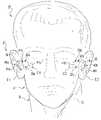
- FIG. 1is a front view of a hearing system as worn by a user, with portions of the system obscured by the user's body being shown in phantom.
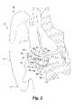
- FIG. 2is a partial schematic view illustrating further details of In-The-Ear (ITE) canal devices of FIG. 1 relative to a partial sectional view of the user's right ear.
- ITEIn-The-Ear
- FIG. 3is a perspective view of the ITE devices of the system of FIG. 1
- FIG. 4is an end view of the ITE devices of the system of FIG. 1 .
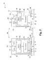
- FIG. 5is a schematic diagram of the system of FIG. 1 .
- FIG. 6is a front view of another hearing system as worn by a user, with an implant device of the system shown in phantom.
- FIG. 7is a side view of a Behind-The-Ear (BTE) device of the system of FIG. 6 relative to the user's left ear, with portions of the user's pinna of the left ear covering the BTE device shown in phantom to enhance clarity.
- BTEBehind-The-Ear
- FIG. 8is a partial, sectional view of the BTE device of FIG. 7 taken along section line 8 - 8 of FIG. 7 .
- FIG. 9is a partial, sectional view of the BTE device of FIG. 7 taken along section line 9 - 9 of FIG. 7 .
- FIG. 10is a diagrammatic view of the BTE device and cochlear implant of the system of FIG. 6 relative to various structures of the user's right ear shown in partial section.
- FIG. 11is a schematic diagram of the system of FIG. 6 .
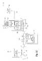
- FIG. 12is a schematic diagram of yet another hearing system.
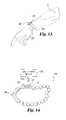
- FIG. 13is a partial diagrammatic view of a first type of hearing system control device as worn by a user.
- FIG. 14is a partial diagrammatic view of a second type of hearing system control device.
- FIG. 15is a partial schematic view of still another hearing system.
- FIG. 16is a side view of a BTE device of a further hearing system.
- FIG. 17is a partial, sectional view of the BTE device of FIG. 16 .
- One embodiment of the present inventionis directed to an intrabody communication system that utilizes the user's body as an electrical signal transmission line.
- this systemis utilized to provide a Body Area Network (BAN) to communicate between various body-worn devices, such as a headset with one or more earphones and/or one or more microphones, a Personal Digital Assistant (PDA), a mobile phone, a medical monitoring and/or treatment unit, and the like.
- BANBody Area Network
- PDAPersonal Digital Assistant
- this systemis utilized to communicate between components of a hearing system to enhance normal hearing or impaired hearing of a person.
- FIG. 1depicts an upper portion of body B of a person (user U) carrying hearing system devices 30 .
- Body Bincludes ears E 1 and E 2 with corresponding ear canals C 1 and C 2 shown in phantom.
- Devices 30are each at least partially placed in the ear canal C 1 or C 2 of ear E 1 and E 2 , respectively; and portions of devices 30 within the ear canals C 1 or C 2 are shown in phantom in FIG. 1 .
- Devices 30are more specifically designated In-The-Ear (ITE) devices 40 a and 40 b.
- Devices 40 a and 40 binclude respective housings 41 a and 41 b.
- ITEIn-The-Ear
- Housings 41 a, 41 bcan be provided in one or more standardized shapes and/or sizes, or can be customized through molding or another procedure to the shape and size of the ear canals of a specific person. Housings 41 a and 41 b are each made from an electrical insulator.
- FIGS. 2-4further details concerning device 40 a as positioned in canal C 1 are shown, it being understood that device 40 b is similarly configured, but is not depicted in FIG. 2 to enhance clarity.
- FIG. 2provides a more detailed view of device 40 a relative to the structures of ear E 1 and body structures in the vicinity of ear E 1 .
- FIG. 3presents a perspective view of devices 40 a and 40 b.
- FIG. 3further illustrates the curvilinear contours in three dimensions of devices 40 a and 40 b arranged to generally conform to the approximate S-shape of ear canals C 1 and C 2 , respectively.
- FIG. 4presents an end view of housing 41 a and 41 b, showing end portions 41 c and 41 d, respectively that are positioned inside ears E 1 and E 2 when devices 40 a and 40 b are placed in the respective ear canals C 1 and C 2 .
- End portions 41 c and 41 dare each shown with an aperture to facilitate the delivery of a hearing stimulus as is further described hereinafter.
- Opposite end portions 41 c and 41 dare corresponding end portions 41 e and 41 f of housings 41 a and 41 b, respectively. End portions 41 e and 41 f are visible at the exterior opening of ear canal C 1 when device 40 a is worn in a normal fashion.
- End portions 41 e and 41 fare also each shown with an aperture to facilitate reception of sound as is further described hereinafter.
- Housing 41 aincludes upper side portion 49 a opposite lower side portion 49 b
- housing 41 bincludes upper side portion 49 c opposite lower side portion 49 d.
- Side portions 49 a and 49 bare positioned between and joining together end portions 41 c and 41 e
- side portions 49 c and 49 dare positioned between and joining together end portions 41 d and 41 f.
- Devices 40 a and 40 beach include a pair of electrodes 32 configured to contact skin S of body B along respective ear canals C 1 and C 2 , and/or be placed in close proximity to skin S.
- close proximitybetween two objects means within two (2) millimeters of one another.
- Electrodes 32operate to transmit and receive signals through skin S of the body B by utilizing body B positioned between devices 40 a and 40 b to communicate information-containing electrical signals. For the purposes of such communications, it has been found that the performance of electrodes 32 can, as a pair, be modeled as a near-field electromagnetic signal radiator and receptor of a dipole antenna type, utilizing skin S and/or other tissues of body B as transmission media.
- each pair of electrodes 32 of devices 40 a and 40 bare also designated as dipole antenna 32 a in FIG. 2 .
- electrodes 32 of device 40 aare alternatively designated antenna constituent 42 a and antenna constituent 44 a; and electrodes 32 of device 40 b are alternatively designated antenna constituent 42 b and antenna constituent 44 b.
- Antenna constituent 42 ais disposed generally opposite antenna constituent 44 a along corresponding opposing side portions 49 a and 49 b of housing 41 a
- antenna constituent 42 bis disposed generally opposite antenna constituent 44 b along corresponding opposing side portions 49 c and 49 d of housing 41 b.
- electrodes 32include a metallic member 34 and a dielectric layer 36 covering at least a portion of member 34 .
- Dielectric layer 36is selected to capacitively couple the corresponding member 34 with skin S of Body B and to protect member 34 from corrosion or other deterioration due to contact with body B.
- metallic member 34is in the form of a 3 millimeter by 10 millimeter copper strip having a thickness of about 90 micrometers and dielectric layer 36 is in the form of a 90 micrometer thick, standard hearing aid lacquer.
- a relatively thinner dielectric layer 36 of about 8 micrometers of Galxyl-paryleneis utilized.
- member 34 and/or dielectric layer 36can be utilized for member 34 and/or dielectric layer 36 as would occur to those skilled in the art.
- dielectric layer 36is absent. It should be understood that the specific shape of electrodes 32 and/or spacing between electrodes may vary with differently sized and/or shaped housings.
- devices 40 a and 40 beach include sound sensor 45 in the form of microphone 45 a.
- Microphone 45 acan be of an omnidirectional type, or a directional type such as those with a cardioid, hypercardioid, or figure-8 directional pattern to name just a few.
- Each device 40 a, 40 bcan include more than one sound sensor and/or microphone 45 a can be of a type that includes multiple sound-detecting elements.
- Collectively sensors 45 of devices 40 a and 40 bdefine sensing array 45 b.
- Devices 40 a and 40 balso each include at least one hearing stimulator 47 in the form of earphone 47 a.
- Housing 41 a and 41 beach define a respective cavity 43 a and 43 b, that each contain circuitry 48 .
- circuitry 48includes signal processor 48 a and transceiver 48 b coupled together to bidirectionally communicate signals therebetween.
- Signal processor 48 ais coupled to sensor 45 to receive input signals therefrom, and to stimulator 47 to provide output signals thereto.
- Transceiver 48 bis coupled to electrodes 32 .
- Signal processor 48 amay be comprised of one or more components of a digital type, analog type or a combination of these operable to perform desired operations as described hereinafter.
- Signal processor 48 acan be of a programmable variety responsive to programming instructions stored in memory of a volatile and/or nonvolatile type, be of a dedicated hardwired logic variety, and/or execute logic defined by both dedicated hardware and program instructions.
- Signal processorcan include only a single central processing unit or a number of processing units. For multiple processing unit embodiments, parallel and/or pipeline processing may be utilized.
- signal processor 48 ais based on a customized, digital signal processor in the form of a solid-state, integrated circuit device.
- Transceiverrefers broadly to any device having a capability to transmit and receive information.
- Transceiver 48 bincludes a transmitter (not shown) and receiver (not shown) both coupled to electrodes 32 to transmit and receive information-containing electrical signals. These electrical signals are typically transmitted in a modulated format that conveys digital information, including but not limited to one or more of the following: Amplitude Shift Keying (ASK), a Frequency Shift Keying (FSK), Phase Shift Keying (PSK), Pulse Width Modulation (PWM), or Pulse Amplitude Modulation (PAM), Quadrature Amplitude Modulation (QAM), Orthogonal Frequency Division Multiplexing (OFDM), or spread spectrum techniques.
- ASKAmplitude Shift Keying
- FSKFrequency Shift Keying
- PSKPhase Shift Keying
- PWMPulse Width Modulation
- PAMPulse Amplitude Modulation
- QAMQuadrature Amplitude Modulation
- an analog signal format and/or modulation techniquesuch as analog Amplitude Modulation (AM) or Frequency Modulation (FM)
- AMAmplitude Modulation
- FMFrequency Modulation
- the transmitterincludes a drive amplifier to output an electrical signal that generates a desired electric potential level across electrodes 32 while in contact with skin S.
- Components of transceiver 48 bare selected to provide a desired level of impedance matching with skin S, including, but not limited to baluns, predefined cable lengths, and/or other passive components, just to name a few.
- Circuitry 48further includes any power supplies (not shown), filters, signal conditioners, format converters (such as analog-to-digital and/or digital-to-analog converters), volatile memories, nonvolatile memories, and the like desired to perform its operations. Electrical power can be provided in the form of an electrochemical cell or battery and/or a different source as would occur to those skilled in the art.
- Devices 40 a and 40 bare positioned in ear canals C 1 and C 2 , respectively.
- antenna constituent 42 a of device 40 a and antenna constituent 42 b of device 40 beach contact or are in close proximity to upper skin regions 26 a and 26 b ( FIGS. 1 and 2 ) along a top portion of ear canals C 1 and C 2 .
- antenna constituent 44 a of device 40 a and antenna constituent 44 b of device 40 beach contact or are in close proximity to lower skin regions 28 a and 28 b ( FIGS. 1 and 2 ) along a bottom portion of ear canals C 1 and C 2 .
- signals from signal processor 48 a of the transmitting device 30are encoded with the corresponding transceiver 48 b and output as a time-varying electric potential across electrodes 32 of such device 30 .
- the receiving device 30detects the time-varying electrical signals with its transceiver 48 b and decodes such signals for use by its signal processor 48 a.
- the preferred range of carrier frequencies for such information-containing electrical signalsis in a range of about 3 MegaHertz (MHz) through about 30 GigaHertz (GHz). A more preferred range is about 10 MHz through about 1 GHz.
- This form of electrical signal communicationuses skin S and/or other tissues of body B as a transmission line, such that at least two spaced apart electrodes, forming a dipole antenna, contact or are in close proximity to body B at each transmission and reception site.
- other techniqueshave at most only one contact pathway, relying instead on a pathway through Earth ground or the atmosphere to provide an electrical potential difference necessary to provide a closed loop pathway for electrical signal communication.
- the bidirectional (two-way) communication of signals through body B via pairs of electrodes 32 for each of device 30is represented by a double-headed arrow.
- one or more of devices 30can be configured for only one-way communication, being limited to just transmission or reception.
- Consistent coupling of electrodes 32 to skin Sis generally desirable because it provides for more consistent transmission characteristics of electrical signals through body B. It has been found that the anterior and posterior sides of the ear canals tend to change shape with nominal movements of the jaw, such as talking and eating, making consistent contact with electrodes 32 of devices 40 a and 40 b difficult. In contrast, movements of the top and bottom portions of the ear canals with nominal jaw movements are generally much less.
- Electrodes 32can be placed in a manner to contact and/or be proximate to skin S along the top and/or bottom portions of the ear canal (such as skin regions 26 a, 26 b, 28 a, and 28 b ).
- antennae pairson opposite sides of housing 41 a and 41 b has been found to reduce capacitance between antennae that also provides a more desirable impedance level for communications via human skin.
- one or more electrodesmay be located along skin in an anterior or posterior region along the ear canal and/or two or more electrodes (antennae) may not be positioned opposite one another.
- “upper,” “lower,” “top,” “bottom,” “anterior, “posterior,” “front,” and “back”refer to relative positions of features of a user's body when the user's body is in an upright sitting or standing position.
- the corresponding sensors 45are utilized to pick up sound which is converted into an electrical input signal that is provided to circuitry 48 .
- the sound signals from the spaced apart sensors 45can be utilized to selectively enhance sound originating from a particular direction relative to sounds (noise) from other directions utilizing a fixed or adaptive beamforming routine, and/or other binaural signal processing routine for a hearing aid or system as described, for example, in International Patent Applications Nos. PCT/US01/15047, PCT/US01/14945, or PCT/US99/26965; U.S. patent application Ser. Nos. 09/805,233, 09/568,435, or 09/568,430; and/or U.S.
- At least one of devices 40 a and 40 breceives sound-representative signals from sensor 45 of the other of devices 40 a and 40 b to generate an enhanced output signal for one of stimulators 47 to stimulate hearing of the user.
- bidirectional communications between devices 40 a and 40 bare envisioned as part of the execution of routines of the type referenced hereinbefore. Further, communications between device 40 a and 40 b can be desired to share processing workload between the corresponding signal processors 48 a in a distributed manner and/or to perform diagnostic or troubleshooting routines of one device 30 with another device 30 .
- devices 40 a and 40 bare shown as being of an In-The-Ear (ITE) type, one or more of these devices can be of a Completely-In-The-Ear-Canal (CIC) type or Behind-The-Ear (BTE) type.
- ITEIn-The-Ear
- CICCompletely-In-The-Ear-Canal
- BTEBehind-The-Ear
- FIG. 6illustrates another communication system 120 where like reference numerals refer to like features previously described in connection with system 20 .
- System 120is in the form of hearing system 121 .
- System 121includes three hearing system devices 130 .
- Devices 130are more specifically designated Behind-the-Ear (BTE) devices 140 a and 140 b, and implant 140 c.
- BTEBehind-the-Ear
- devices 140 a and 140 beach include housing 141 and each include a pair of spaced apart electrodes 132 .
- Housing 141is shaped to fit behind either ear E 1 and E 2 of body B of system user U. When positioned behind ear El or E 2 , housing 141 is generally located between the corresponding pinna P 1 or P 2 and cranial region CR 1 or CR 2 of the user U, respectively.
- Housing 141is made from an electrical insulator. Housing 141 includes a lower portion 141 a opposite an upper portion 141 b joined together by two opposing sides 141 c. At its lowest extreme, portion 141 a defines a lower contour 141 d.
- Lower contour 141 dis schematically indicated by a corresponding dashed line of heavier weight in FIG. 7 .
- Lower contour 141 dgenerally defines a hook-shape to facilitate behind-the-ear fitting.
- Lower contour 141 dcan be curvilinear, rectilinear, or a combination of both.
- the hook-shape of lower contour 141 dsubtends an angle A about the corresponding pinna P 2 .
- angle Ais between about 60 and 120 degrees. More preferably, angle A is between about 75 and 105 degrees. Still more preferable, angle A is approximately 90 degrees. Nonetheless, in other embodiments, a different angle A can be utilized.
- Electrodes 132are each comprised of a metallic member 134 and a dielectric layer 136 at least partially covering the metallic member 134 as best shown in FIGS. 8 , 9 , and 11 .
- the composition of members 134 and/or layer 136can be as described in connection with member 34 and dielectric layer 36 of electrodes 32 .
- each of the upper electrodes 132are alternatively designated antenna constituent 142
- each of the lower electrodes 132are alternatively designated antenna constituent 144 .
- Antenna constituents 142 and 144are operable as a dipole antenna in the near field as alternatively designated by reference numeral 132 a in FIGS. 8 and 9 .
- antenna constituent 142was provided in the form of a 9 millimeter wide copper strip and antenna constituent 144 was provided in the form of a 15 millimeter wide copper strip both having a thickness of 90 micrometers.
- antenna constituent 142 , 144 and/or dielectric layer 136can be utilized as would occur to those skilled in the art.
- Housing 141is generally symmetric about a plane that intersects contour 141 a.
- This plane of symmetry (POS)is perpendicular to the view plane of FIGS. 8-10 , being represented by the axis labeled POS.
- the plane of symmetryis parallel to the view plane of FIG. 7 .
- antenna constituent 142extends from lower contour 141 d (represented by cross-hairs) to either of opposing sides 141 c to present a U or V shape that wraps around the plane of symmetry represented by axis POS and, like housing 141 , is generally symmetric about this plane.
- FIG. 8antenna constituent 142 extends from lower contour 141 d (represented by cross-hairs) to either of opposing sides 141 c to present a U or V shape that wraps around the plane of symmetry represented by axis POS and, like housing 141 , is generally symmetric about this plane.
- antenna constituent 144extends from lower contour 141 d (represented by cross-hairs) to opposing sides 141 c to present a U or V shape that wraps around the plane of symmetry represented by axis POS and, like housing 141 , is generally symmetric about this plane.
- the symmetry of housing 141 , antenna constituent 142 and antenna constituent 144 with respect to the plane represented in FIGS. 8 and 9facilitates the interchangeability of devices 140 a and 140 b between right and left ears E 1 and E 2 , respectively.
- antenna constituents 142 and 144are separated from one another along contour 141 d by at least 10 millimeters to reduce capacitance therebetween.
- the separation distance between antenna constituent 142 and 144 along contour 141 d of housing 141is at least 15 millimeters. In a still more preferred embodiment, this separation distance is at least 20 millimeters.
- antenna constituent 142 and 144are arranged along housing 141 so that antenna constituent 142 contacts or is in close proximity to skin region 126 a above an uppermost extreme 129 a of concha C of the ear and antenna constituent 144 contacts or is in close proximity to skin region 126 b at a level below extreme 129 a as illustrated in FIG. 7 .
- antenna constituent 142contacts or is proximal to skin region 126 a at a point above and anterior to skin region 126 b as positioned relative to antenna constituent 144 .
- Antenna constituent 142 and 144can contact or be proximal to skin S that joins the pinnae P 1 , P 2 and corresponding cranial regions CR 1 , CR 2 ; skin S on the pinnae P 1 , P 2 ; and/or skin on cranial regions CR 1 , CR 2 ; respectively.
- each device 140 a and 140 bincludes a sound sensor 145 in the form of microphone 145 a that can be any of the types previously described. Collectively, sensors 145 of devices 140 a and 140 b define a sound sensing array 147 . Housing 141 defines cavity 146 to contain circuitry 148 . Circuitry 148 includes transceiver 148 b coupled to corresponding antenna constituents 142 and 144 . Transceiver 148 b is of the type described in connection with system 20 . Circuitry 148 also includes signal processor 148 a that can be configured in any of the ways described for signal processor 48 a, with its programmed and/or hardwired logic adapted to perform operations described hereinafter for system 120 .
- Circuitry 148further includes any power supplies (not shown), filters, signal conditioners, format converters (such as analog-to-digital and/or digital-to-analog converters), volatile memories, nonvolatile memories, and the like desired to perform its operations. Electrical power can be provided in the form of an electrochemical cell or battery and/or a different source as would occur to those skilled in the art.
- Implant 140 cis illustrated in FIG. 10 relative to various internal structures associated with ear E 1 and in an operational schematic form in the diagram of FIG. 11 .
- Implant 140 cincludes enclosure 161 encapsulating signal processing circuitry 168 .
- Enclosure 161is implanted in the mastoid region of ear E 1 .
- enclosure 161is made from titanium, a ceramic material, or such other body-compatible material as would occur to those skilled in the art.
- Signal processing circuitryincludes signal processor 168 a and transceiver 168 b.
- Implant 140 calso includes hearing stimulation apparatus 170 coupled to signal processing circuitry 168 via one or more wires or cables from enclosure 161 .
- Hearing stimulation apparatus 170includes middle ear actuator 172 coupled to the middle ear region in the vicinity of the auditory canal.
- Hearing stimulation apparatus 170also includes an electromechanical intracochlear actuator 174 , such as a bone conduction cochlear stimulator coupled to the small bones of the ear (malleus, incus, and/or stapes), and intracochlear stimulation electrodes 176 implanted within the cochlea. It should be understood that more or fewer hearing stimulation apparatus, or perhaps only one of these hearing stimulators could be used in other embodiments.
- Implant 140 cfurther includes auditory canal microphone 180 coupled to circuitry 168 via cabling. Microphone 180 can be used to detect acoustic signals in addition to or in lieu of sensors 145 to enhance natural sound perception of the user.
- Devices 140 a and 140 bare arranged to pick up sound with array 147 and bidirectionally communicate using body B as an electrical signal transmission line between corresponding pairs of antenna constituents 142 and 144 in the manner previously described for the devices 40 a and 40 b of system 20 .
- one or more of signal processors 148 a of devices 140 a and 140 bcan be configured to generate an output in accordance with a fixed or adaptive beamforming routine and/or other binaural signal processing routine.
- implant 140 creceives the output from device 140 a and/or 140 b to correspondingly stimulate hearing of the user U with one or more of the hearing stimulation apparatus 170 previously described.
- Bidirectional communication between devices 140 a and 140 b, and implant 140 cis represented by double-headed arrows in FIG. 11 .
- Implant 140 c and one or more of devices 140 a and 140 bcan be by a wire or cable connection, through magnetic induction with an induction coil, through electrical signal transmission utilizing electrodes of the type provided for communication between devices 140 a and 140 b, through ultrasonic communication, and/or through such different means as would occur to those skilled in the art.
- implant 140 cis only configured to receive communication signals.
- one or more of devices 140 a and 140 bcan be arranged to only transmit or receive signals via electrodes 32 .
- implant 140 cis provided in a hearing system with one or more ITE and/or CIC hearing system devices that communicate via electrode pairs.
- microphone 180is typically absent.
- One or more ITE or CIC hearing system devices in these arrangementscan be used in addition to or in place of corresponding BTE hearing system devices.
- FIG. 12schematically illustrates communication system 220 including ear-worn hearing system devices 230 each coupled to skin S of body B by a pair of electrodes 232 .
- Devices 230can be configured the same as ITE devices 40 a and 40 b, BTE devices 140 a and 140 b, or a combination of these.
- electrodes 232are configured the same as electrodes 32 or 132 , and each pairing of electrodes 232 for a device is alternatively designated dipole antenna 232 a.
- System 220further includes hearing system control device 240 with a corresponding electrode pair 232 .
- Device 240provides user control over system 220 and an off-body communication interface with off-body device 290 .
- Device 240can be provided in different forms, including but not limited to eyeglasses, a headband, a necklace and the like; or in the form of a wrist worn device 241 with a coupling wrist band or strap 241 a as shown in FIG. 13 . Indeed, device 240 can be integrated into a wristwatch or made to appear as one.
- the WATCHPILOTprovided by PHONAK AG, which has a business address of Laubisrütistrasse 28, 8712 Stäfa, Switzerland, could be adapted to such use.
- Device 240includes user control 242 arranged to provide input through one or more push buttons, rotary dials, switches, or the like.
- Device 240also includes indicator 243 to provide user-observable output.
- Indicator 243is typically in the form of a Liquid Crystal Display (LCD) or Light Emitting Diode (LED) display, but can be differently configured as would occur to those skilled in the art.
- Device 240also includes off-body communication interface 245 , which can be of a cable connected variety, wireless variety, or a combination of such varieties. In one wireless Radio Frequency (RF) based form, communication is performed in accordance with a BLUETOOTH or AUTOCOM standard, and/or a MICROLINK or MLX standard from PHONAK AG. In addition or as an alternative, interface 245 can communicate through another wireless technique and/or by cable connection.
- RFRadio Frequency
- Device 240further includes signal processing/communication circuitry 268 coupled to control 242 , indicator 243 , and interface 245 .
- circuitry 268includes one or more signal processing units operable to execute programmed and/or hardwired logic to facilitate Input and/or Output (I/O) via control 242 , indicator 243 , interface 245 , and perform any desired data modifications, conversions, storage, or the like; and includes any signal conditioners, filters, format converters (such as analog-to-digital and/or digital-to-analog types), amplifiers, power sources, or the like to implement desired operations as would occur to those skilled in the art.
- Device 240communicates with devices 230 through a time-varying electrical signal transmitted through body B via electrodes 232 in the manner previously described in connection with systems 20 and 120 .
- Interface 245operatively connects with off-body device 290 via a communication link represented by the doubled headed arrow designated with reference numeral 245 c.
- This communication linkcan be of a temporary or relatively permanent type.
- Off-body device 290can be arranged as an audio satellite, providing a remote audio input to the user from a Public Address System (PAS), telephonic communication link, one or more remote microphones, an entertainment source such as a radio, television, MP3 player, tape player, CD player, etc. and/or a different type of audio satellite as would occur to those skilled in the art, just to name a few.
- PASPublic Address System
- off-body device 290can provide data and/or parametric values used in the operation of system 220 .
- Interface 245can also be used in conjunction with device 290 to perform testing of one or more devices 230 and/or of system 220 collectively; communicate system or device diagnosis; and/or system/device performance data.
- FIG. 14depicts a partial diagrammatic view of communication system 320 , where like reference numerals refer to like features.
- System 320can include one or more of the ear worn devices of systems 20 , 120 , and 220 and/or one or more implants 140 c (not shown) that communicate with time-varying electrical signals transmitted through body B.
- System 320includes an alternative body-worn control device in the form of jewelry that is depicted as bracelet 340 with control device 341 .
- Bracelet 340is shown interfaced with off-body device 290 , and includes electrodes 232 .
- Control device 341can incorporate the features of device 240 .
- an earringis utilized that clips to an earlobe of the user.
- two or more control devicescan be utilized and/or one or more implants may also be included.
- a control devicecan be used in lieu of one or more ear-worn modules, such as ITE, CIC, or BTE devices.
- a control deviceis not worn or carried on the body, but instead is temporarily used to provide audio input, perform diagnostic testing, update/modify software, or perform such different operation as would occur to those skilled in the art.
- ear-to-ear communicationcan be utilized between BTE devices 140 a and 140 b of system 120 to implement a fixed or adaptive beamformer routine or a different binaural routine.
- at least one of BTE devices 140 a and 140 bis configured with an earphone to stimulate hearing of user U with adaptation to operate in the manner described for devices 40 a and 40 b of system 20 , and implant 140 c being absent.
- System 420 depicted in FIG. 15provides an example of a BTE device 440 with earphone 447 a.
- FIG. 15illustrates still another communication system 420 where like reference numerals refer to like features previously described.
- System 420is in the form of hearing system 421 that includes hearing system devices 440 and 460 .
- Hearing system device 440includes member 440 a coupled to member 440 b by member 440 c.
- Member 440 aincludes a rigid housing member 441 a shaped and configured to fit behind the ear E 1 of a person's body B. Housing member 441 a can be shaped the same as housing 141 of devices 140 a and 140 b described in connection with system 121 .
- Member 440 aalso includes sensor 145 in the form of microphone 145 a as previously described, and a hearing stimulator 447 that can be of the type described in connection with devices 40 a and 40 b of system 20 .
- Sensor 145is immediately above stimulator 447 .
- member 440 ahouses circuitry 448 that is configured the same as circuitry 48 , 148 , and/or variations thereof to perform fixed beamforming, adaptive beamforming, and/or different binaural routines with adaptation to include logic to operate device 440 according to the manner described hereinafter.
- Circuitry 448is operatively coupled to sensor 145 and hearing stimulator 447 .
- Member 440 bis in partial schematic, sectional form in FIG. 15 .
- Member 440 bincludes housing member 441 b shaped to fit in ear canal C 1 in the manner described in connection with device 40 a of system 20 .
- Member 440 bdefines passageway 450 to transmit sound to ear E 1 received from member 440 c.
- Member 440 cincludes flexible housing 441 c in the form of coupling tube 443 with a passage to transmit this sound from hearing stimulator 447 of member 440 a to passageway 450 of member 440 b.
- Housing 441 cis flexible to permit articulation of members 440 a and 440 b relative to one another such that member 440 b can be readily removed from and inserted in canal C 1 while member 440 a is mounted behind ear E 1 .
- Device 440includes a pair of electrodes 432 configured to provide a dipole antenna designated by reference numeral 432 a. Electrode 432 carried with member 440 a is alternatively designated antenna constituent 442 , and electrode 442 carried with member 440 b is alternatively designated antenna constituent 444 . Further, antenna constituent 444 is shown embedded within member 440 b such that portion 446 of member 440 b is positioned between skin S 1 along ear canal C 1 and antenna constituent 444 . Portion 446 is comprised of a dielectric material to facilitate capacitive coupling of antenna constituent 444 to body B. Electrodes 432 are composed of a metallic material or other suitable electrical conductor. Electrodes 432 are each operatively coupled to circuitry 448 . In the case of antenna constituent 444 , coupling to circuitry 448 can be accomplished by a cable or wire (not shown) that extends through or is carried with housing member 441 c.
- System 421can operate in the same manner as system 21 to enhance normal hearing and/or impaired hearing.
- Device 460can be another device 440 ; device 40 b, 140 a, or 140 b; or another of the various hearing systems devices previously described, such as a CIC, control device (with or without an off-body interface), and/or implant, to name just a few. Communication between device 440 and 460 can be performed in the same manner as described for previous devices via electrode pairs with each pair operating as a dipole antenna in close proximity to or contact with body B.
- FIGS. 16 and 17illustrate yet another communication system 520 .
- System 520includes hearing system device 540 in the form of a behind-the-ear unit and other hearing system device(s) 560 .
- Device 540includes housing 541 that can be shaped the same as housing 141 of device 140 a or 140 b previously described.
- Device 540further includes a number of internal electrodes 532 (four of which are shown). Electrodes 532 are carried within interior 543 of device 540 and are operatively coupled to user control 542 .
- Device 540also includes user control 542 coupled to electrodes 532 .
- control 542is a momentary push-button that can be used to provide an input pulse.
- Device 540also includes sensor 145 in the form of microphone 145 a as previously described.
- Electrodes 532are separated from outer surface 541 a of housing 541 along lowermost contour 541 d by portions 549 of housing 541 . Electrodes 532 are positioned to contact interior surface 543 a of housing 541 , and have more specific individual designations 532 a, 532 b, 532 c, and 532 d. In one form, electrodes 532 are plated or otherwise deposited on surface 543 a using standard techniques, and are comprised of a metallic material or other suitable electrical conductor. Portions 549 are comprised of a dielectric material configured to capacitively couple electrodes 532 to skin when device 540 is worn behind the ear of a user.
- circuitry 548 of device 540that is carried in interior 543 of housing 541 .
- Circuitry 548can be configured the same as previously described circuitry 48 , 148 , and/or variations thereof to perform fixed beamforming, adaptive beamforming, and/or a different binaural routine with the exception of adaptations to include logic to operate device 540 according to the manner described hereinafter.
- Circuitry 548is operatively coupled to electrodes 532 , control 542 , and sensor 145 . With circuitry 548 , any pair of electrodes 532 can be utilized as a dipole antenna to communicate through the body of a user in the manner previously described.
- FIG. 17also shows a representative cross-section of one of electrodes 532 illustrating its symmetry about axis POS; where axis POS is coextensive with a plane of symmetry for housing 541 and electrodes 532 to facilitate interchange of device 540 between right and left ears.
- circuitry 548responds to an input from control 542 , to successively cause different pairs of electrodes 532 to become active and correspondingly form a dipole antenna. Accordingly, an operator of device 540 can select between different pairings of electrodes 532 to find which electrode pair operates best for communication purposes with one or more of other device(s) 560 ( FIG. 16 ).
- control 542is a momentary pushbutton type
- Circuitry 548 of device 540responds to this signal to activate a different one of a number of pairings of electrodes 532 .
- a typical initial pairincludes electrodes 532 separated from one another by the greatest distance, specifically electrodes 532 a and 532 d.
- Other pairings selectable with control 542include: electrodes 532 a and 532 c; electrodes 532 a and 532 b; electrodes 532 b and 532 c; electrodes 532 b and 532 d; and electrodes 532 c and 532 d.
- not all of the possible unique pairingsare offered as an option and the technique to switch from one to the next may differ.
- selectioncan be done with a different type of control and/or can be done in response to programming or another automatic procedure.
- the pairingis selected via an off-body unit.
- the remaining electrodesare not typically utilized to perform communications—being in an inactive state.
- more or fewer electrodescould be utilized than the four illustrated in FIG. 16 .
- different active pairingscan be selected among possible pairings of three or more electrodes; where some or all of these electrodes are exterior to the device housing and may or may not otherwise include a dielectric covering.
- electrode pairing selection for devices having three or more electrodescould be utilized with ITC devices, CIC devices, control devices, and the like for other hearing system configurations of the type described herein, or as would otherwise occur to those skilled in the art. Further, it is envisioned that alternative pairings of electrodes for intrabody communication systems and networks other than those used to enhance normal hearing or impaired hearing could be utilized.
- any of the communication techniques and arrangements of the present applicationcould be utilized for systems other than those directed to enhancement of normal or impaired hearing.
- user controlled computing devicessuch as Personal Digital Assistants (PDAs) could be coupled to an intrabody network with a corresponding electrode pair operating as dipole antennae.
- medical diagnostic and/or treatment devicescould communicate in such a fashion.
- mobile phones, microphones, headphones, virtual reality devices and various other units that may or may not involve hearing and sound receptioncould utilize dipole antenna communication via electrode pairs of any of types described in connection with the systems 20 , 120 , 220 , 320 , 420 , and 520 to participate in a body area network.
Landscapes
- Engineering & Computer Science (AREA)
- Computer Networks & Wireless Communication (AREA)
- Health & Medical Sciences (AREA)
- General Health & Medical Sciences (AREA)
- Neurosurgery (AREA)
- Otolaryngology (AREA)
- Physics & Mathematics (AREA)
- Acoustics & Sound (AREA)
- Signal Processing (AREA)
- Prostheses (AREA)
- Measurement And Recording Of Electrical Phenomena And Electrical Characteristics Of The Living Body (AREA)
- Headphones And Earphones (AREA)
Abstract
Description
Claims (43)
Priority Applications (9)
| Application Number | Priority Date | Filing Date | Title |
|---|---|---|---|
| US10/340,529US7512448B2 (en) | 2003-01-10 | 2003-01-10 | Electrode placement for wireless intrabody communication between components of a hearing system |
| DE602004024956TDE602004024956D1 (en) | 2003-01-10 | 2004-01-09 | SYSTEMS, DEVICES AND METHOD FOR WIRELESS INTRAKÖRPER COMMUNICATION |
| CA2512794ACA2512794C (en) | 2003-01-10 | 2004-01-09 | Systems, devices, and methods of wireless intrabody communication |
| DK04701266.1TDK1584216T3 (en) | 2003-01-10 | 2004-01-09 | Systems, devices and methods for wireless intracorporeal communication |
| AU2004205043AAU2004205043B2 (en) | 2003-01-10 | 2004-01-09 | Systems, devices, and methods of wireless intrabody communication |
| EP04701266AEP1584216B1 (en) | 2003-01-10 | 2004-01-09 | Systems, devices, and methods of wireless intrabody communication |
| EP10000002AEP2169982A3 (en) | 2003-01-10 | 2004-01-09 | Systems, devices, and methods of wireless intrabody communication |
| JP2006500890AJP2006516852A (en) | 2003-01-10 | 2004-01-09 | Wireless in-vivo communication system, apparatus and method |
| PCT/US2004/000602WO2004064450A2 (en) | 2003-01-10 | 2004-01-09 | Systems, devices, and methods of wireless intrabody communication |
Applications Claiming Priority (1)
| Application Number | Priority Date | Filing Date | Title |
|---|---|---|---|
| US10/340,529US7512448B2 (en) | 2003-01-10 | 2003-01-10 | Electrode placement for wireless intrabody communication between components of a hearing system |
Publications (2)
| Publication Number | Publication Date |
|---|---|
| US20040138723A1 US20040138723A1 (en) | 2004-07-15 |
| US7512448B2true US7512448B2 (en) | 2009-03-31 |
Family
ID=32711350
Family Applications (1)
| Application Number | Title | Priority Date | Filing Date |
|---|---|---|---|
| US10/340,529Active - Reinstated2025-12-15US7512448B2 (en) | 2003-01-10 | 2003-01-10 | Electrode placement for wireless intrabody communication between components of a hearing system |
Country Status (8)
| Country | Link |
|---|---|
| US (1) | US7512448B2 (en) |
| EP (2) | EP1584216B1 (en) |
| JP (1) | JP2006516852A (en) |
| AU (1) | AU2004205043B2 (en) |
| CA (1) | CA2512794C (en) |
| DE (1) | DE602004024956D1 (en) |
| DK (1) | DK1584216T3 (en) |
| WO (1) | WO2004064450A2 (en) |
Cited By (156)
| Publication number | Priority date | Publication date | Assignee | Title |
|---|---|---|---|---|
| USD598469S1 (en)* | 2008-06-23 | 2009-08-18 | Harris Jr Leon | Combination MP3 player/ear piece |
| US20090268932A1 (en)* | 2006-05-30 | 2009-10-29 | Sonitus Medical, Inc. | Microphone placement for oral applications |
| US20100081894A1 (en)* | 2005-04-28 | 2010-04-01 | Proteus Biomedical, Inc. | Communication system with partial power source |
| US20110026740A1 (en)* | 2006-05-30 | 2011-02-03 | Sonitus Medical, Inc. | Methods and apparatus for processing audio signals |
| US20110065983A1 (en)* | 2008-08-13 | 2011-03-17 | Hooman Hafezi | Ingestible Circuitry |
| US8036748B2 (en) | 2008-11-13 | 2011-10-11 | Proteus Biomedical, Inc. | Ingestible therapy activator system and method |
| US8054140B2 (en) | 2006-10-17 | 2011-11-08 | Proteus Biomedical, Inc. | Low voltage oscillator for medical devices |
| US8055334B2 (en) | 2008-12-11 | 2011-11-08 | Proteus Biomedical, Inc. | Evaluation of gastrointestinal function using portable electroviscerography systems and methods of using the same |
| US8114021B2 (en) | 2008-12-15 | 2012-02-14 | Proteus Biomedical, Inc. | Body-associated receiver and method |
| US8115618B2 (en) | 2007-05-24 | 2012-02-14 | Proteus Biomedical, Inc. | RFID antenna for in-body device |
| US8258962B2 (en) | 2008-03-05 | 2012-09-04 | Proteus Biomedical, Inc. | Multi-mode communication ingestible event markers and systems, and methods of using the same |
| US8352046B1 (en)* | 2009-01-30 | 2013-01-08 | Advanced Bionics, Llc | Sound processing assembly for use in a cochlear implant system |
| US20130030321A1 (en)* | 2011-07-29 | 2013-01-31 | Ming Zhang | Concha electrode |
| US8412352B2 (en) | 2011-01-28 | 2013-04-02 | Medtronic, Inc. | Communication dipole for implantable medical device |
| US8515559B2 (en) | 2011-01-28 | 2013-08-20 | Medtronic, Inc. | Communication dipole for implantable medical device |
| US8540664B2 (en) | 2009-03-25 | 2013-09-24 | Proteus Digital Health, Inc. | Probablistic pharmacokinetic and pharmacodynamic modeling |
| US8547248B2 (en) | 2005-09-01 | 2013-10-01 | Proteus Digital Health, Inc. | Implantable zero-wire communications system |
| US8545402B2 (en) | 2009-04-28 | 2013-10-01 | Proteus Digital Health, Inc. | Highly reliable ingestible event markers and methods for using the same |
| US8558563B2 (en) | 2009-08-21 | 2013-10-15 | Proteus Digital Health, Inc. | Apparatus and method for measuring biochemical parameters |
| US8597186B2 (en) | 2009-01-06 | 2013-12-03 | Proteus Digital Health, Inc. | Pharmaceutical dosages delivery system |
| US8639335B2 (en) | 2011-01-28 | 2014-01-28 | Medtronic, Inc. | Disabling an implanted medical device with another medical device |
| US8718193B2 (en) | 2006-11-20 | 2014-05-06 | Proteus Digital Health, Inc. | Active signal processing personal health signal receivers |
| US8730031B2 (en) | 2005-04-28 | 2014-05-20 | Proteus Digital Health, Inc. | Communication system using an implantable device |
| US8784308B2 (en) | 2009-12-02 | 2014-07-22 | Proteus Digital Health, Inc. | Integrated ingestible event marker system with pharmaceutical product |
| US8802183B2 (en) | 2005-04-28 | 2014-08-12 | Proteus Digital Health, Inc. | Communication system with enhanced partial power source and method of manufacturing same |
| US8836513B2 (en) | 2006-04-28 | 2014-09-16 | Proteus Digital Health, Inc. | Communication system incorporated in an ingestible product |
| US8858432B2 (en) | 2007-02-01 | 2014-10-14 | Proteus Digital Health, Inc. | Ingestible event marker systems |
| US8868453B2 (en) | 2009-11-04 | 2014-10-21 | Proteus Digital Health, Inc. | System for supply chain management |
| US8912908B2 (en) | 2005-04-28 | 2014-12-16 | Proteus Digital Health, Inc. | Communication system with remote activation |
| US8932221B2 (en) | 2007-03-09 | 2015-01-13 | Proteus Digital Health, Inc. | In-body device having a multi-directional transmitter |
| US8945005B2 (en) | 2006-10-25 | 2015-02-03 | Proteus Digital Health, Inc. | Controlled activation ingestible identifier |
| US8956287B2 (en) | 2006-05-02 | 2015-02-17 | Proteus Digital Health, Inc. | Patient customized therapeutic regimens |
| US8956288B2 (en) | 2007-02-14 | 2015-02-17 | Proteus Digital Health, Inc. | In-body power source having high surface area electrode |
| US8961412B2 (en) | 2007-09-25 | 2015-02-24 | Proteus Digital Health, Inc. | In-body device with virtual dipole signal amplification |
| US9002467B2 (en) | 2005-05-18 | 2015-04-07 | Cardiac Pacemakers, Inc. | Modular antitachyarrhythmia therapy system |
| US9014779B2 (en) | 2010-02-01 | 2015-04-21 | Proteus Digital Health, Inc. | Data gathering system |
| US9107806B2 (en) | 2010-11-22 | 2015-08-18 | Proteus Digital Health, Inc. | Ingestible device with pharmaceutical product |
| US9144688B2 (en) | 2012-11-12 | 2015-09-29 | Empi, Inc. | Systems and methods for wireless pairing and communication for electro-stimulation |
| US9149423B2 (en) | 2009-05-12 | 2015-10-06 | Proteus Digital Health, Inc. | Ingestible event markers comprising an ingestible component |
| US9198608B2 (en) | 2005-04-28 | 2015-12-01 | Proteus Digital Health, Inc. | Communication system incorporated in a container |
| US9235683B2 (en) | 2011-11-09 | 2016-01-12 | Proteus Digital Health, Inc. | Apparatus, system, and method for managing adherence to a regimen |
| US9268909B2 (en) | 2012-10-18 | 2016-02-23 | Proteus Digital Health, Inc. | Apparatus, system, and method to adaptively optimize power dissipation and broadcast power in a power source for a communication device |
| US9270025B2 (en) | 2007-03-09 | 2016-02-23 | Proteus Digital Health, Inc. | In-body device having deployable antenna |
| US9270503B2 (en) | 2013-09-20 | 2016-02-23 | Proteus Digital Health, Inc. | Methods, devices and systems for receiving and decoding a signal in the presence of noise using slices and warping |
| US9271897B2 (en) | 2012-07-23 | 2016-03-01 | Proteus Digital Health, Inc. | Techniques for manufacturing ingestible event markers comprising an ingestible component |
| US9357316B2 (en)* | 2010-12-06 | 2016-05-31 | Nxp B.V. | Time division multiplexed access method of operating a near field communication system and a near field communication system operating the same |
| US9351648B2 (en) | 2012-08-24 | 2016-05-31 | Medtronic, Inc. | Implantable medical device electrode assembly |
| US9439599B2 (en) | 2011-03-11 | 2016-09-13 | Proteus Digital Health, Inc. | Wearable personal body associated device with various physical configurations |
| US9439566B2 (en) | 2008-12-15 | 2016-09-13 | Proteus Digital Health, Inc. | Re-wearable wireless device |
| US9526909B2 (en) | 2014-08-28 | 2016-12-27 | Cardiac Pacemakers, Inc. | Medical device with triggered blanking period |
| US9577864B2 (en) | 2013-09-24 | 2017-02-21 | Proteus Digital Health, Inc. | Method and apparatus for use with received electromagnetic signal at a frequency not known exactly in advance |
| US9592391B2 (en) | 2014-01-10 | 2017-03-14 | Cardiac Pacemakers, Inc. | Systems and methods for detecting cardiac arrhythmias |
| US9597487B2 (en) | 2010-04-07 | 2017-03-21 | Proteus Digital Health, Inc. | Miniature ingestible device |
| US9603550B2 (en) | 2008-07-08 | 2017-03-28 | Proteus Digital Health, Inc. | State characterization based on multi-variate data fusion techniques |
| US9659423B2 (en) | 2008-12-15 | 2017-05-23 | Proteus Digital Health, Inc. | Personal authentication apparatus system and method |
| US9669230B2 (en) | 2015-02-06 | 2017-06-06 | Cardiac Pacemakers, Inc. | Systems and methods for treating cardiac arrhythmias |
| US9694189B2 (en) | 2014-08-06 | 2017-07-04 | Cardiac Pacemakers, Inc. | Method and apparatus for communicating between medical devices |
| US9757570B2 (en) | 2014-08-06 | 2017-09-12 | Cardiac Pacemakers, Inc. | Communications in a medical device system |
| US9756874B2 (en) | 2011-07-11 | 2017-09-12 | Proteus Digital Health, Inc. | Masticable ingestible product and communication system therefor |
| US9796576B2 (en) | 2013-08-30 | 2017-10-24 | Proteus Digital Health, Inc. | Container with electronically controlled interlock |
| US9808631B2 (en) | 2014-08-06 | 2017-11-07 | Cardiac Pacemakers, Inc. | Communication between a plurality of medical devices using time delays between communication pulses to distinguish between symbols |
| US9853743B2 (en) | 2015-08-20 | 2017-12-26 | Cardiac Pacemakers, Inc. | Systems and methods for communication between medical devices |
| US9855425B2 (en) | 2006-05-05 | 2018-01-02 | Advanced Bionics Ag | Information processing and storage in a cochlear stimulation system |
| US9867990B2 (en) | 2010-10-29 | 2018-01-16 | Medtronic, Inc. | Determination of dipole for tissue conductance communication |
| US9883819B2 (en) | 2009-01-06 | 2018-02-06 | Proteus Digital Health, Inc. | Ingestion-related biofeedback and personalized medical therapy method and system |
| US9956414B2 (en) | 2015-08-27 | 2018-05-01 | Cardiac Pacemakers, Inc. | Temporal configuration of a motion sensor in an implantable medical device |
| US9968787B2 (en) | 2015-08-27 | 2018-05-15 | Cardiac Pacemakers, Inc. | Spatial configuration of a motion sensor in an implantable medical device |
| US20180192207A1 (en)* | 2016-12-30 | 2018-07-05 | Gn Hearing A/S | Modular hearing instrument comprising electro-acoustic calibration parameters |
| US10029107B1 (en) | 2017-01-26 | 2018-07-24 | Cardiac Pacemakers, Inc. | Leadless device with overmolded components |
| US10046167B2 (en) | 2015-02-09 | 2018-08-14 | Cardiac Pacemakers, Inc. | Implantable medical device with radiopaque ID tag |
| US10050700B2 (en) | 2015-03-18 | 2018-08-14 | Cardiac Pacemakers, Inc. | Communications in a medical device system with temporal optimization |
| US10065041B2 (en) | 2015-10-08 | 2018-09-04 | Cardiac Pacemakers, Inc. | Devices and methods for adjusting pacing rates in an implantable medical device |
| US10084880B2 (en) | 2013-11-04 | 2018-09-25 | Proteus Digital Health, Inc. | Social media networking based on physiologic information |
| US10092760B2 (en) | 2015-09-11 | 2018-10-09 | Cardiac Pacemakers, Inc. | Arrhythmia detection and confirmation |
| US10137305B2 (en) | 2015-08-28 | 2018-11-27 | Cardiac Pacemakers, Inc. | Systems and methods for behaviorally responsive signal detection and therapy delivery |
| US10159842B2 (en) | 2015-08-28 | 2018-12-25 | Cardiac Pacemakers, Inc. | System and method for detecting tamponade |
| US10175376B2 (en) | 2013-03-15 | 2019-01-08 | Proteus Digital Health, Inc. | Metal detector apparatus, system, and method |
| US10187121B2 (en) | 2016-07-22 | 2019-01-22 | Proteus Digital Health, Inc. | Electromagnetic sensing and detection of ingestible event markers |
| US10183170B2 (en) | 2015-12-17 | 2019-01-22 | Cardiac Pacemakers, Inc. | Conducted communication in a medical device system |
| US10213610B2 (en) | 2015-03-18 | 2019-02-26 | Cardiac Pacemakers, Inc. | Communications in a medical device system with link quality assessment |
| US10223905B2 (en) | 2011-07-21 | 2019-03-05 | Proteus Digital Health, Inc. | Mobile device and system for detection and communication of information received from an ingestible device |
| US10220213B2 (en) | 2015-02-06 | 2019-03-05 | Cardiac Pacemakers, Inc. | Systems and methods for safe delivery of electrical stimulation therapy |
| US10226631B2 (en) | 2015-08-28 | 2019-03-12 | Cardiac Pacemakers, Inc. | Systems and methods for infarct detection |
| US10255422B1 (en) | 2014-09-15 | 2019-04-09 | Apple Inc. | Identity proxy for access control systems |
| US10328272B2 (en) | 2016-05-10 | 2019-06-25 | Cardiac Pacemakers, Inc. | Retrievability for implantable medical devices |
| US10350423B2 (en) | 2016-02-04 | 2019-07-16 | Cardiac Pacemakers, Inc. | Delivery system with force sensor for leadless cardiac device |
| US10357159B2 (en) | 2015-08-20 | 2019-07-23 | Cardiac Pacemakers, Inc | Systems and methods for communication between medical devices |
| US10396948B2 (en) | 2015-01-07 | 2019-08-27 | Northeastern University | Ultrasonic multiplexing network for implantable medical devices |
| US10391319B2 (en) | 2016-08-19 | 2019-08-27 | Cardiac Pacemakers, Inc. | Trans septal implantable medical device |
| US10398161B2 (en) | 2014-01-21 | 2019-09-03 | Proteus Digital Heal Th, Inc. | Masticable ingestible product and communication system therefor |
| US10413733B2 (en) | 2016-10-27 | 2019-09-17 | Cardiac Pacemakers, Inc. | Implantable medical device with gyroscope |
| US10426962B2 (en) | 2016-07-07 | 2019-10-01 | Cardiac Pacemakers, Inc. | Leadless pacemaker using pressure measurements for pacing capture verification |
| US10434314B2 (en) | 2016-10-27 | 2019-10-08 | Cardiac Pacemakers, Inc. | Use of a separate device in managing the pace pulse energy of a cardiac pacemaker |
| US10434317B2 (en) | 2016-10-31 | 2019-10-08 | Cardiac Pacemakers, Inc. | Systems and methods for activity level pacing |
| US10463305B2 (en) | 2016-10-27 | 2019-11-05 | Cardiac Pacemakers, Inc. | Multi-device cardiac resynchronization therapy with timing enhancements |
| US10484805B2 (en) | 2009-10-02 | 2019-11-19 | Soundmed, Llc | Intraoral appliance for sound transmission via bone conduction |
| US10512784B2 (en) | 2016-06-27 | 2019-12-24 | Cardiac Pacemakers, Inc. | Cardiac therapy system using subcutaneously sensed P-waves for resynchronization pacing management |
| US10529044B2 (en) | 2010-05-19 | 2020-01-07 | Proteus Digital Health, Inc. | Tracking and delivery confirmation of pharmaceutical products |
| US10561330B2 (en) | 2016-10-27 | 2020-02-18 | Cardiac Pacemakers, Inc. | Implantable medical device having a sense channel with performance adjustment |
| US10583301B2 (en) | 2016-11-08 | 2020-03-10 | Cardiac Pacemakers, Inc. | Implantable medical device for atrial deployment |
| US10583303B2 (en) | 2016-01-19 | 2020-03-10 | Cardiac Pacemakers, Inc. | Devices and methods for wirelessly recharging a rechargeable battery of an implantable medical device |
| US10617874B2 (en) | 2016-10-31 | 2020-04-14 | Cardiac Pacemakers, Inc. | Systems and methods for activity level pacing |
| US10632313B2 (en) | 2016-11-09 | 2020-04-28 | Cardiac Pacemakers, Inc. | Systems, devices, and methods for setting cardiac pacing pulse parameters for a cardiac pacing device |
| US10639486B2 (en) | 2016-11-21 | 2020-05-05 | Cardiac Pacemakers, Inc. | Implantable medical device with recharge coil |
| US10668294B2 (en) | 2016-05-10 | 2020-06-02 | Cardiac Pacemakers, Inc. | Leadless cardiac pacemaker configured for over the wire delivery |
| US10688304B2 (en) | 2016-07-20 | 2020-06-23 | Cardiac Pacemakers, Inc. | Method and system for utilizing an atrial contraction timing fiducial in a leadless cardiac pacemaker system |
| US10722720B2 (en) | 2014-01-10 | 2020-07-28 | Cardiac Pacemakers, Inc. | Methods and systems for improved communication between medical devices |
| US10737102B2 (en) | 2017-01-26 | 2020-08-11 | Cardiac Pacemakers, Inc. | Leadless implantable device with detachable fixation |
| US10758724B2 (en) | 2016-10-27 | 2020-09-01 | Cardiac Pacemakers, Inc. | Implantable medical device delivery system with integrated sensor |
| US10758737B2 (en) | 2016-09-21 | 2020-09-01 | Cardiac Pacemakers, Inc. | Using sensor data from an intracardially implanted medical device to influence operation of an extracardially implantable cardioverter |
| US10765871B2 (en) | 2016-10-27 | 2020-09-08 | Cardiac Pacemakers, Inc. | Implantable medical device with pressure sensor |
| US10780278B2 (en) | 2016-08-24 | 2020-09-22 | Cardiac Pacemakers, Inc. | Integrated multi-device cardiac resynchronization therapy using P-wave to pace timing |
| US10821288B2 (en) | 2017-04-03 | 2020-11-03 | Cardiac Pacemakers, Inc. | Cardiac pacemaker with pacing pulse energy adjustment based on sensed heart rate |
| US10835753B2 (en) | 2017-01-26 | 2020-11-17 | Cardiac Pacemakers, Inc. | Intra-body device communication with redundant message transmission |
| US10870008B2 (en) | 2016-08-24 | 2020-12-22 | Cardiac Pacemakers, Inc. | Cardiac resynchronization using fusion promotion for timing management |
| US10874861B2 (en) | 2018-01-04 | 2020-12-29 | Cardiac Pacemakers, Inc. | Dual chamber pacing without beat-to-beat communication |
| US10881869B2 (en) | 2016-11-21 | 2021-01-05 | Cardiac Pacemakers, Inc. | Wireless re-charge of an implantable medical device |
| US10881863B2 (en) | 2016-11-21 | 2021-01-05 | Cardiac Pacemakers, Inc. | Leadless cardiac pacemaker with multimode communication |
| US10894163B2 (en) | 2016-11-21 | 2021-01-19 | Cardiac Pacemakers, Inc. | LCP based predictive timing for cardiac resynchronization |
| US10905872B2 (en) | 2017-04-03 | 2021-02-02 | Cardiac Pacemakers, Inc. | Implantable medical device with a movable electrode biased toward an extended position |
| US10905886B2 (en) | 2015-12-28 | 2021-02-02 | Cardiac Pacemakers, Inc. | Implantable medical device for deployment across the atrioventricular septum |
| US10905889B2 (en) | 2016-09-21 | 2021-02-02 | Cardiac Pacemakers, Inc. | Leadless stimulation device with a housing that houses internal components of the leadless stimulation device and functions as the battery case and a terminal of an internal battery |
| US10918875B2 (en) | 2017-08-18 | 2021-02-16 | Cardiac Pacemakers, Inc. | Implantable medical device with a flux concentrator and a receiving coil disposed about the flux concentrator |
| US10994145B2 (en) | 2016-09-21 | 2021-05-04 | Cardiac Pacemakers, Inc. | Implantable cardiac monitor |
| US11052258B2 (en) | 2017-12-01 | 2021-07-06 | Cardiac Pacemakers, Inc. | Methods and systems for detecting atrial contraction timing fiducials within a search window from a ventricularly implanted leadless cardiac pacemaker |
| US11051543B2 (en) | 2015-07-21 | 2021-07-06 | Otsuka Pharmaceutical Co. Ltd. | Alginate on adhesive bilayer laminate film |
| US11058880B2 (en) | 2018-03-23 | 2021-07-13 | Medtronic, Inc. | VFA cardiac therapy for tachycardia |
| US11065459B2 (en) | 2017-08-18 | 2021-07-20 | Cardiac Pacemakers, Inc. | Implantable medical device with pressure sensor |
| US11071870B2 (en) | 2017-12-01 | 2021-07-27 | Cardiac Pacemakers, Inc. | Methods and systems for detecting atrial contraction timing fiducials and determining a cardiac interval from a ventricularly implanted leadless cardiac pacemaker |
| US11116988B2 (en) | 2016-03-31 | 2021-09-14 | Cardiac Pacemakers, Inc. | Implantable medical device with rechargeable battery |
| US11149123B2 (en) | 2013-01-29 | 2021-10-19 | Otsuka Pharmaceutical Co., Ltd. | Highly-swellable polymeric films and compositions comprising the same |
| US11147979B2 (en) | 2016-11-21 | 2021-10-19 | Cardiac Pacemakers, Inc. | Implantable medical device with a magnetically permeable housing and an inductive coil disposed about the housing |
| US11158149B2 (en) | 2013-03-15 | 2021-10-26 | Otsuka Pharmaceutical Co., Ltd. | Personal authentication apparatus system and method |
| US11185703B2 (en) | 2017-11-07 | 2021-11-30 | Cardiac Pacemakers, Inc. | Leadless cardiac pacemaker for bundle of his pacing |
| US11207527B2 (en) | 2016-07-06 | 2021-12-28 | Cardiac Pacemakers, Inc. | Method and system for determining an atrial contraction timing fiducial in a leadless cardiac pacemaker system |
| US11207532B2 (en) | 2017-01-04 | 2021-12-28 | Cardiac Pacemakers, Inc. | Dynamic sensing updates using postural input in a multiple device cardiac rhythm management system |
| US11213676B2 (en) | 2019-04-01 | 2022-01-04 | Medtronic, Inc. | Delivery systems for VfA cardiac therapy |
| US11235159B2 (en) | 2018-03-23 | 2022-02-01 | Medtronic, Inc. | VFA cardiac resynchronization therapy |
| US11235163B2 (en) | 2017-09-20 | 2022-02-01 | Cardiac Pacemakers, Inc. | Implantable medical device with multiple modes of operation |
| US11235161B2 (en) | 2018-09-26 | 2022-02-01 | Medtronic, Inc. | Capture in ventricle-from-atrium cardiac therapy |
| US11260216B2 (en) | 2017-12-01 | 2022-03-01 | Cardiac Pacemakers, Inc. | Methods and systems for detecting atrial contraction timing fiducials during ventricular filling from a ventricularly implanted leadless cardiac pacemaker |
| US11285326B2 (en) | 2015-03-04 | 2022-03-29 | Cardiac Pacemakers, Inc. | Systems and methods for treating cardiac arrhythmias |
| US11305127B2 (en) | 2019-08-26 | 2022-04-19 | Medtronic Inc. | VfA delivery and implant region detection |
| US11400296B2 (en) | 2018-03-23 | 2022-08-02 | Medtronic, Inc. | AV synchronous VfA cardiac therapy |
| US11529071B2 (en) | 2016-10-26 | 2022-12-20 | Otsuka Pharmaceutical Co., Ltd. | Methods for manufacturing capsules with ingestible event markers |
| US11529523B2 (en) | 2018-01-04 | 2022-12-20 | Cardiac Pacemakers, Inc. | Handheld bridge device for providing a communication bridge between an implanted medical device and a smartphone |
| US11679265B2 (en) | 2019-02-14 | 2023-06-20 | Medtronic, Inc. | Lead-in-lead systems and methods for cardiac therapy |
| US11697025B2 (en) | 2019-03-29 | 2023-07-11 | Medtronic, Inc. | Cardiac conduction system capture |
| US11712188B2 (en) | 2019-05-07 | 2023-08-01 | Medtronic, Inc. | Posterior left bundle branch engagement |
| US11744481B2 (en) | 2013-03-15 | 2023-09-05 | Otsuka Pharmaceutical Co., Ltd. | System, apparatus and methods for data collection and assessing outcomes |
| US11813463B2 (en) | 2017-12-01 | 2023-11-14 | Cardiac Pacemakers, Inc. | Leadless cardiac pacemaker with reversionary behavior |
| US11813464B2 (en) | 2020-07-31 | 2023-11-14 | Medtronic, Inc. | Cardiac conduction system evaluation |
| US11813466B2 (en) | 2020-01-27 | 2023-11-14 | Medtronic, Inc. | Atrioventricular nodal stimulation |
| US11911168B2 (en) | 2020-04-03 | 2024-02-27 | Medtronic, Inc. | Cardiac conduction system therapy benefit determination |
| US11951313B2 (en) | 2018-11-17 | 2024-04-09 | Medtronic, Inc. | VFA delivery systems and methods |
| US12296177B2 (en) | 2018-12-21 | 2025-05-13 | Medtronic, Inc. | Delivery systems and methods for left ventricular pacing |
Families Citing this family (85)
| Publication number | Priority date | Publication date | Assignee | Title |
|---|---|---|---|---|
| US7392091B2 (en)* | 2003-12-30 | 2008-06-24 | Cochlear Limited | Implanted antenna and radio communications link |
| JP4026648B2 (en)* | 2004-04-19 | 2007-12-26 | ソニー株式会社 | Earphone antenna and portable radio equipped with the earphone antenna |
| JP3933148B2 (en)* | 2004-06-04 | 2007-06-20 | ソニー株式会社 | Earphone antenna and portable radio equipped with the earphone antenna |
| TWI277355B (en)* | 2004-07-08 | 2007-03-21 | Sony Corp | Earphone antenna connecting device and portable wireless device |
| KR100851089B1 (en)* | 2004-08-27 | 2008-08-08 | 빅토리온 테크놀러지 씨오., 엘티디. | Nasal conduction wireless communication transmitter |
| EP1821432B1 (en)* | 2004-12-08 | 2011-07-06 | Seiko Instruments Inc. | Information transmission through-human-body system and transmitter/receiver |
| US7856275B1 (en)* | 2005-01-07 | 2010-12-21 | Ric Investments, Llc | Vestibular system stimulation apparatus |
| US20060236120A1 (en)* | 2005-04-14 | 2006-10-19 | Ibm Corporation | Method and apparatus employing stress detection for highly secure communication |
| US20060236121A1 (en)* | 2005-04-14 | 2006-10-19 | Ibm Corporation | Method and apparatus for highly secure communication |
| US7355090B2 (en)* | 2005-08-31 | 2008-04-08 | Kimberly-Clark Worldwide, Inc. | Method of detecting the presence of insults in an absorbent article |
| US7649125B2 (en)* | 2005-08-31 | 2010-01-19 | Kimberly-Clark Worldwide, Inc. | Method of detecting the presence of an insult in an absorbent article and device for detecting the same |
| US7498478B2 (en)* | 2005-08-31 | 2009-03-03 | Kimberly-Clark Worldwide, Inc. | Method of detecting the presence of an insult in an absorbent article |
| US7548211B2 (en)* | 2006-03-30 | 2009-06-16 | Phonak Ag | Wireless audio signal receiver device for a hearing instrument |
| US20080049961A1 (en)* | 2006-08-24 | 2008-02-28 | Brindisi Thomas J | Personal audio player |
| US8364274B1 (en) | 2006-12-29 | 2013-01-29 | Advanced Bionics, Llc | Systems and methods for detecting one or more central auditory potentials |
| US7706885B2 (en)* | 2007-02-23 | 2010-04-27 | Gradient Technologies, Llc | Transcutaneous electrical nerve stimulation and method of using same |
| US8934984B2 (en)* | 2007-05-31 | 2015-01-13 | Cochlear Limited | Behind-the-ear (BTE) prosthetic device with antenna |
| EP2197536A1 (en)* | 2007-10-09 | 2010-06-23 | Imthera Medical, Inc. | System and method for neural stimulation |
| US8634773B2 (en)* | 2007-10-12 | 2014-01-21 | Cochlear Limited | Short range communications for body contacting devices |
| US20100290651A1 (en)* | 2007-11-01 | 2010-11-18 | The University Of Melbourne | Pulse stimulation generation method |
| EP2104378B2 (en)* | 2008-02-19 | 2017-05-10 | Starkey Laboratories, Inc. | Wireless beacon system to identify acoustic environment for hearing assistance devices |
| EP2265331B2 (en) | 2008-03-28 | 2025-03-19 | Cochlear Limited | Antenna for behind-the-ear (bte) devices |
| US8503930B2 (en)* | 2008-04-25 | 2013-08-06 | Sonitus Medical, Inc. | Signal transmission via body conduction |
| US8588448B1 (en) | 2008-09-09 | 2013-11-19 | Energy Telecom, Inc. | Communication eyewear assembly |
| AU2008246284A1 (en)* | 2008-11-19 | 2010-06-10 | Zao, Ritm Okb | Method for electrical influance on a living organism and device thereof |
| ES2388488T3 (en) | 2008-12-23 | 2012-10-15 | Koninklijke Philips Electronics N.V. | Combination of body coupled communication and radio frequency communication |
| EP2392085B1 (en)* | 2009-01-28 | 2021-06-23 | Samsung Electronics Co., Ltd. | Portable terminal and sound detector, which both communicate using body area network, and data controlling method therefor |
| EP2408519B1 (en) | 2009-03-16 | 2016-08-31 | Cochlear Limited | Transcutaneous modulated power link for a medical implant |
| US8726492B2 (en)* | 2009-09-09 | 2014-05-20 | Cochlear Limited | Insulated conductive element having a substantially continuous barrier layer formed through multiple coatings |
| US8460746B2 (en)* | 2009-09-09 | 2013-06-11 | Cochlear Limited | Method of forming insulated conductive element having a substantially continuous barrier layer formed via relative motion during deposition |
| EP2545718A4 (en)* | 2010-03-10 | 2013-08-14 | Energy Telecom Inc | Communication eyewear assembly |
| WO2010133702A2 (en) | 2010-09-15 | 2010-11-25 | Advanced Bionics Ag | Partially implantable hearing instrument |
| DK2725655T3 (en) | 2010-10-12 | 2021-09-20 | Gn Hearing As | Antenna system for a hearing aid |
| US12115374B2 (en) | 2011-01-28 | 2024-10-15 | Curonix Llc | Microwave field stimulator |
| CA2831062A1 (en) | 2011-01-28 | 2012-08-02 | Stimwave Technologies Incorporated | Neural stimulator system |
| WO2012138782A1 (en) | 2011-04-04 | 2012-10-11 | Stimwave Technologies Incorporated | Implantable lead |
| US9220897B2 (en) | 2011-04-04 | 2015-12-29 | Micron Devices Llc | Implantable lead |
| US8954177B2 (en) | 2011-06-01 | 2015-02-10 | Apple Inc. | Controlling operation of a media device based upon whether a presentation device is currently being worn by a user |
| US11083391B2 (en) | 2011-06-10 | 2021-08-10 | Cochlear Limited | Electrode impedance spectroscopy |
| CN104080509B (en) | 2011-07-29 | 2017-09-08 | 米克伦设备有限责任公司 | Remote control for power or polarity selection of neurostimulators |
| WO2013025632A1 (en) | 2011-08-12 | 2013-02-21 | Stimwave Technologies Incorporated | Microwave field stimulator |
| SG11201400166XA (en) | 2011-08-24 | 2014-03-28 | Widex As | Eeg monitor with capacitive electrodes and method of monitoring brain waves |
| CA2848998A1 (en) | 2011-09-15 | 2013-03-21 | Stimwave Technologies Incorporated | Relay module for implant |
| JP5841267B2 (en)* | 2012-02-13 | 2016-01-13 | ジアンス ベターライフ メディカル カンパニー リミテッドJiangsu Betterlife Medical Co., Ltd | Digital hearing aid |
| US9319807B2 (en)* | 2012-02-28 | 2016-04-19 | Cochlear Limited | Device with combined antenna and transducer |
| US8903502B2 (en)* | 2012-05-21 | 2014-12-02 | Micron Devices Llc | Methods and devices for modulating excitable tissue of the exiting spinal nerves |
| DK2667638T3 (en) | 2012-05-24 | 2016-05-09 | Oticon As | Hearing aid with external electrode |
| US9648409B2 (en) | 2012-07-12 | 2017-05-09 | Apple Inc. | Earphones with ear presence sensors |
| US20140023216A1 (en)* | 2012-07-17 | 2014-01-23 | Starkey Laboratories, Inc. | Hearing assistance device with wireless communication for on- and off- body accessories |
| US9344792B2 (en) | 2012-11-29 | 2016-05-17 | Apple Inc. | Ear presence detection in noise cancelling earphones |
| US9049508B2 (en) | 2012-11-29 | 2015-06-02 | Apple Inc. | Earphones with cable orientation sensors |
| US20140146982A1 (en) | 2012-11-29 | 2014-05-29 | Apple Inc. | Electronic Devices and Accessories with Media Streaming Control Features |
| US8744113B1 (en) | 2012-12-13 | 2014-06-03 | Energy Telecom, Inc. | Communication eyewear assembly with zone of safety capability |
| US9254393B2 (en) | 2012-12-26 | 2016-02-09 | Micron Devices Llc | Wearable antenna assembly |
| US9532147B2 (en) | 2013-07-19 | 2016-12-27 | Starkey Laboratories, Inc. | System for detection of special environments for hearing assistance devices |
| US9883295B2 (en) | 2013-11-11 | 2018-01-30 | Gn Hearing A/S | Hearing aid with an antenna |
| US9686621B2 (en) | 2013-11-11 | 2017-06-20 | Gn Hearing A/S | Hearing aid with an antenna |
| US9888328B2 (en)* | 2013-12-02 | 2018-02-06 | Arizona Board Of Regents On Behalf Of Arizona State University | Hearing assistive device |
| US10009069B2 (en)* | 2014-05-05 | 2018-06-26 | Nxp B.V. | Wireless power delivery and data link |
| CN106256090B (en)* | 2014-05-05 | 2020-10-13 | 恩智浦有限公司 | Electromagnetic induction wireless communication system, method and storage medium |
| US10014578B2 (en) | 2014-05-05 | 2018-07-03 | Nxp B.V. | Body antenna system |
| US10015604B2 (en)* | 2014-05-05 | 2018-07-03 | Nxp B.V. | Electromagnetic induction field communication |
| US9819075B2 (en)* | 2014-05-05 | 2017-11-14 | Nxp B.V. | Body communication antenna |
| US9812788B2 (en) | 2014-11-24 | 2017-11-07 | Nxp B.V. | Electromagnetic field induction for inter-body and transverse body communication |
| US9819395B2 (en)* | 2014-05-05 | 2017-11-14 | Nxp B.V. | Apparatus and method for wireless body communication |
| CN110665114B (en) | 2014-05-12 | 2022-12-06 | 斯蒂维科技公司 | Remote RF power system with small size transmit antenna |
| US10595138B2 (en) | 2014-08-15 | 2020-03-17 | Gn Hearing A/S | Hearing aid with an antenna |
| DK3180927T3 (en) | 2014-08-15 | 2020-05-04 | Ihear Medical Inc | CHANNEL HEARING AND PROCEDURES FOR WIRELESS REMOTE CONTROL OF A DEVICE |
| US9769577B2 (en) | 2014-08-22 | 2017-09-19 | iHear Medical, Inc. | Hearing device and methods for wireless remote control of an appliance |
| EP3188792B1 (en) | 2014-09-02 | 2021-11-24 | Cochlear Limited | Intra-cochlear stimulating assembly insertion |
| US10097933B2 (en) | 2014-10-06 | 2018-10-09 | iHear Medical, Inc. | Subscription-controlled charging of a hearing device |
| US20160134742A1 (en) | 2014-11-11 | 2016-05-12 | iHear Medical, Inc. | Subscription-based wireless service for a canal hearing device |
| US10350115B2 (en) | 2015-02-27 | 2019-07-16 | Kimberly-Clark Worldwide, Inc. | Absorbent article leakage assessment system |
| US10052492B2 (en)* | 2015-05-06 | 2018-08-21 | Verily Life Sciences Llc | Replaceable battery for implantable devices |
| US9819097B2 (en) | 2015-08-26 | 2017-11-14 | Nxp B.V. | Antenna system |
| DK3182728T3 (en)* | 2015-12-14 | 2020-01-20 | Gn Hearing As | Hearing aid |
| US10320086B2 (en) | 2016-05-04 | 2019-06-11 | Nxp B.V. | Near-field electromagnetic induction (NFEMI) antenna |
| US11013641B2 (en) | 2017-04-05 | 2021-05-25 | Kimberly-Clark Worldwide, Inc. | Garment for detecting absorbent article leakage and methods of detecting absorbent article leakage utilizing the same |
| EP3506655B1 (en)* | 2017-12-29 | 2024-08-14 | GN Hearing A/S | A hearing instrument comprising a magnetic induction antenna |
| AU2019215179B2 (en) | 2018-02-01 | 2024-11-07 | Curonix Llc | Systems and methods to sense stimulation electrode tissue impedance |
| CN109891761A (en)* | 2019-01-31 | 2019-06-14 | 深圳市汇顶科技股份有限公司 | Transmit method, communication device, portable device and the communication system of information |
| US11064305B2 (en)* | 2019-09-30 | 2021-07-13 | Sonova Ag | Systems and methods for using a selectively configurable interface assembly to program a hearing device |
| DE102020209124A1 (en) | 2020-07-21 | 2022-01-27 | Sivantos Pte. Ltd. | ITE hearing aid |
| US11422392B2 (en)* | 2020-10-05 | 2022-08-23 | Meta Platforms Technologies, Llc | Ultraminiature dynamic speaker for a fully in-ear monitor |
| CN118266232A (en)* | 2022-10-28 | 2024-06-28 | 深圳市韶音科技有限公司 | A headset |
Citations (133)
| Publication number | Priority date | Publication date | Assignee | Title |
|---|---|---|---|---|
| US3123678A (en)* | 1955-12-13 | 1964-03-03 | Zenith Radio Corp | Prent |
| US4025721A (en) | 1976-05-04 | 1977-05-24 | Biocommunications Research Corporation | Method of and means for adaptively filtering near-stationary noise from speech |
| US4207441A (en) | 1977-03-16 | 1980-06-10 | Bertin & Cie | Auditory prosthesis equipment |
| DE2823798C2 (en) | 1978-05-31 | 1980-07-03 | Siemens Ag, 1000 Berlin Und 8000 Muenchen | Method for electrical stimulation of the auditory nerve and multi-channel hearing prosthesis for carrying out the method |
| US4304235A (en) | 1978-09-12 | 1981-12-08 | Kaufman John George | Electrosurgical electrode |
| US4334740A (en) | 1978-09-12 | 1982-06-15 | Polaroid Corporation | Receiving system having pre-selected directional response |
| US4354064A (en) | 1980-02-19 | 1982-10-12 | Scott Instruments Company | Vibratory aid for presbycusis |
| DE3322108A1 (en) | 1982-03-10 | 1984-12-20 | Siemens AG, 1000 Berlin und 8000 München | Speech alerting device |
| US4536887A (en) | 1982-10-18 | 1985-08-20 | Nippon Telegraph & Telephone Public Corporation | Microphone-array apparatus and method for extracting desired signal |
| US4559642A (en) | 1982-08-27 | 1985-12-17 | Victor Company Of Japan, Limited | Phased-array sound pickup apparatus |
| US4611598A (en) | 1984-05-30 | 1986-09-16 | Hortmann Gmbh | Multi-frequency transmission system for implanted hearing aids |
| US4703506A (en) | 1985-07-23 | 1987-10-27 | Victor Company Of Japan, Ltd. | Directional microphone apparatus |
| US4742548A (en) | 1984-12-20 | 1988-05-03 | American Telephone And Telegraph Company | Unidirectional second order gradient microphone |
| US4752961A (en) | 1985-09-23 | 1988-06-21 | Northern Telecom Limited | Microphone arrangement |
| US4773095A (en) | 1985-10-16 | 1988-09-20 | Siemens Aktiengesellschaft | Hearing aid with locating microphones |
| US4790019A (en) | 1984-07-18 | 1988-12-06 | Viennatone Gesellschaft M.B.H. | Remote hearing aid volume control |
| US4845755A (en) | 1984-08-28 | 1989-07-04 | Siemens Aktiengesellschaft | Remote control hearing aid |
| US4858612A (en) | 1983-12-19 | 1989-08-22 | Stocklin Philip L | Hearing device |
| US4918737A (en) | 1987-07-07 | 1990-04-17 | Siemens Aktiengesellschaft | Hearing aid with wireless remote control |
| US4982434A (en) | 1989-05-30 | 1991-01-01 | Center For Innovative Technology | Supersonic bone conduction hearing aid and method |
| US4988981A (en) | 1987-03-17 | 1991-01-29 | Vpl Research, Inc. | Computer data entry and manipulation apparatus and method |
| US4987897A (en) | 1989-09-18 | 1991-01-29 | Medtronic, Inc. | Body bus medical device communication system |
| US5000194A (en)* | 1988-08-25 | 1991-03-19 | Cochlear Corporation | Array of bipolar electrodes |
| US5012520A (en) | 1988-05-06 | 1991-04-30 | Siemens Aktiengesellschaft | Hearing aid with wireless remote control |
| US5029216A (en) | 1989-06-09 | 1991-07-02 | The United States Of America As Represented By The Administrator Of The National Aeronautics & Space Administration | Visual aid for the hearing impaired |
| US5040156A (en) | 1989-06-29 | 1991-08-13 | Battelle-Institut E.V. | Acoustic sensor device with noise suppression |
| US5047994A (en) | 1989-05-30 | 1991-09-10 | Center For Innovative Technology | Supersonic bone conduction hearing aid and method |
| US5113859A (en) | 1988-09-19 | 1992-05-19 | Medtronic, Inc. | Acoustic body bus medical device communication system |
| US5245556A (en) | 1992-09-15 | 1993-09-14 | Universal Data Systems, Inc. | Adaptive equalizer method and apparatus |
| US5259032A (en) | 1990-11-07 | 1993-11-02 | Resound Corporation | contact transducer assembly for hearing devices |
| US5285499A (en) | 1993-04-27 | 1994-02-08 | Signal Science, Inc. | Ultrasonic frequency expansion processor |
| US5289544A (en) | 1991-12-31 | 1994-02-22 | Audiological Engineering Corporation | Method and apparatus for reducing background noise in communication systems and for enhancing binaural hearing systems for the hearing impaired |
| US5321332A (en) | 1992-11-12 | 1994-06-14 | The Whitaker Corporation | Wideband ultrasonic transducer |
| US5325436A (en) | 1993-06-30 | 1994-06-28 | House Ear Institute | Method of signal processing for maintaining directional hearing with hearing aids |
| US5383915A (en) | 1991-04-10 | 1995-01-24 | Angeion Corporation | Wireless programmer/repeater system for an implanted medical device |
| US5400409A (en) | 1992-12-23 | 1995-03-21 | Daimler-Benz Ag | Noise-reduction method for noise-affected voice channels |
| US5417113A (en) | 1993-08-18 | 1995-05-23 | The United States Of America As Represented By The Administrator Of The National Aeronautics And Space Administration | Leak detection utilizing analog binaural (VLSI) techniques |
| US5430690A (en) | 1992-03-20 | 1995-07-04 | Abel; Jonathan S. | Method and apparatus for processing signals to extract narrow bandwidth features |
| US5454838A (en) | 1992-07-27 | 1995-10-03 | Sorin Biomedica S.P.A. | Method and a device for monitoring heart function |
| US5463694A (en) | 1993-11-01 | 1995-10-31 | Motorola | Gradient directional microphone system and method therefor |
| US5473701A (en) | 1993-11-05 | 1995-12-05 | At&T Corp. | Adaptive microphone array |
| US5479522A (en) | 1993-09-17 | 1995-12-26 | Audiologic, Inc. | Binaural hearing aid |
| US5485515A (en) | 1993-12-29 | 1996-01-16 | At&T Corp. | Background noise compensation in a telephone network |
| US5495534A (en) | 1990-01-19 | 1996-02-27 | Sony Corporation | Audio signal reproducing apparatus |
| US5507781A (en) | 1991-05-23 | 1996-04-16 | Angeion Corporation | Implantable defibrillator system with capacitor switching circuitry |
| US5511128A (en) | 1994-01-21 | 1996-04-23 | Lindemann; Eric | Dynamic intensity beamforming system for noise reduction in a binaural hearing aid |
| US5550923A (en) | 1994-09-02 | 1996-08-27 | Minnesota Mining And Manufacturing Company | Directional ear device with adaptive bandwidth and gain control |
| US5627799A (en) | 1994-09-01 | 1997-05-06 | Nec Corporation | Beamformer using coefficient restrained adaptive filters for detecting interference signals |
| US5651071A (en) | 1993-09-17 | 1997-07-22 | Audiologic, Inc. | Noise reduction system for binaural hearing aid |
| US5663727A (en) | 1995-06-23 | 1997-09-02 | Hearing Innovations Incorporated | Frequency response analyzer and shaping apparatus and digital hearing enhancement apparatus and method utilizing the same |
| EP0802699A2 (en) | 1997-07-16 | 1997-10-22 | Phonak Ag | Method for electronically enlarging the distance between two acoustical/electrical transducers and hearing aid apparatus |
| US5694474A (en) | 1995-09-18 | 1997-12-02 | Interval Research Corporation | Adaptive filter for signal processing and method therefor |
| US5706352A (en) | 1993-04-07 | 1998-01-06 | K/S Himpp | Adaptive gain and filtering circuit for a sound reproduction system |
| US5715319A (en) | 1996-05-30 | 1998-02-03 | Picturetel Corporation | Method and apparatus for steerable and endfire superdirective microphone arrays with reduced analog-to-digital converter and computational requirements |
| US5721783A (en) | 1995-06-07 | 1998-02-24 | Anderson; James C. | Hearing aid with wireless remote processor |
| EP0824889A1 (en) | 1996-08-20 | 1998-02-25 | Buratto Advanced Technology S.r.l. | Transmission system using the human body as wave guide |
| US5734976A (en) | 1994-03-07 | 1998-03-31 | Phonak Communications Ag | Micro-receiver for receiving a high frequency frequency-modulated or phase-modulated signal |
| US5737430A (en) | 1993-07-22 | 1998-04-07 | Cardinal Sound Labs, Inc. | Directional hearing aid |
| EP0843425A2 (en) | 1996-11-14 | 1998-05-20 | International Business Machines Corporation | Electronic communication apparatus using the human body as a transmission medium |
| US5755748A (en) | 1996-07-24 | 1998-05-26 | Dew Engineering & Development Limited | Transcutaneous energy transfer device |
| US5757932A (en) | 1993-09-17 | 1998-05-26 | Audiologic, Inc. | Digital hearing aid system |
| US5768392A (en) | 1996-04-16 | 1998-06-16 | Aura Systems Inc. | Blind adaptive filtering of unknown signals in unknown noise in quasi-closed loop system |
| US5793875A (en) | 1996-04-22 | 1998-08-11 | Cardinal Sound Labs, Inc. | Directional hearing system |
| WO1998026629A3 (en) | 1996-11-25 | 1998-10-15 | St Croix Medical Inc | Dual path implantable hearing assistance device |
| US5825898A (en) | 1996-06-27 | 1998-10-20 | Lamar Signal Processing Ltd. | System and method for adaptive interference cancelling |
| US5831936A (en) | 1995-02-21 | 1998-11-03 | State Of Israel/Ministry Of Defense Armament Development Authority - Rafael | System and method of noise detection |
| US5833603A (en) | 1996-03-13 | 1998-11-10 | Lipomatrix, Inc. | Implantable biosensing transponder |
| WO1998056459A1 (en) | 1997-06-10 | 1998-12-17 | Telecom Medical, Inc. | Galvanic transdermal conduction communication system and method |
| US5878147A (en) | 1996-12-31 | 1999-03-02 | Etymotic Research, Inc. | Directional microphone assembly |
| US5889870A (en) | 1996-07-17 | 1999-03-30 | American Technology Corporation | Acoustic heterodyne device and method |
| US5914701A (en) | 1995-05-08 | 1999-06-22 | Massachusetts Institute Of Technology | Non-contact system for sensing and signalling by externally induced intra-body currents |
| US5991419A (en) | 1997-04-29 | 1999-11-23 | Beltone Electronics Corporation | Bilateral signal processing prosthesis |
| US6002776A (en) | 1995-09-18 | 1999-12-14 | Interval Research Corporation | Directional acoustic signal processor and method therefor |
| US6009183A (en)* | 1998-06-30 | 1999-12-28 | Resound Corporation | Ambidextrous sound delivery tube system |
| US6023514A (en) | 1997-12-22 | 2000-02-08 | Strandberg; Malcolm W. P. | System and method for factoring a merged wave field into independent components |
| WO2000030404A1 (en) | 1998-11-16 | 2000-05-25 | The Board Of Trustees Of The University Of Illinois | Binaural signal processing techniques |
| US6068589A (en) | 1996-02-15 | 2000-05-30 | Neukermans; Armand P. | Biocompatible fully implantable hearing aid transducers |
| US6094150A (en) | 1997-09-10 | 2000-07-25 | Mitsubishi Heavy Industries, Ltd. | System and method of measuring noise of mobile body using a plurality microphones |
| US6104822A (en) | 1995-10-10 | 2000-08-15 | Audiologic, Inc. | Digital signal processing hearing aid |
| US6118882A (en) | 1995-01-25 | 2000-09-12 | Haynes; Philip Ashley | Communication method |
| DE19541648C2 (en) | 1995-11-08 | 2000-10-05 | Siemens Audiologische Technik | Device for transferring programming data to hearing aids |
| US6137889A (en) | 1998-05-27 | 2000-10-24 | Insonus Medical, Inc. | Direct tympanic membrane excitation via vibrationally conductive assembly |
| US6141591A (en) | 1996-03-06 | 2000-10-31 | Advanced Bionics Corporation | Magnetless implantable stimulator and external transmitter and implant tools for aligning same |
| US6154552A (en) | 1997-05-15 | 2000-11-28 | Planning Systems Inc. | Hybrid adaptive beamformer |
| US6161046A (en) | 1996-04-09 | 2000-12-12 | Maniglia; Anthony J. | Totally implantable cochlear implant for improvement of partial and total sensorineural hearing loss |
| US6160757A (en) | 1997-09-10 | 2000-12-12 | France Telecom S.A. | Antenna formed of a plurality of acoustic pick-ups |
| US6167312A (en) | 1999-04-30 | 2000-12-26 | Medtronic, Inc. | Telemetry system for implantable medical devices |
| US6173062B1 (en) | 1994-03-16 | 2001-01-09 | Hearing Innovations Incorporated | Frequency transpositional hearing aid with digital and single sideband modulation |
| US6182018B1 (en) | 1998-08-25 | 2001-01-30 | Ford Global Technologies, Inc. | Method and apparatus for identifying sound in a composite sound signal |
| WO2001006851A1 (en) | 1999-07-21 | 2001-02-01 | Dow Agrosciences Llc | Pest control techniques |
| US6192134B1 (en) | 1997-11-20 | 2001-02-20 | Conexant Systems, Inc. | System and method for a monolithic directional microphone array |
| US6198693B1 (en) | 1998-04-13 | 2001-03-06 | Andrea Electronics Corporation | System and method for finding the direction of a wave source using an array of sensors |
| US6217508B1 (en) | 1998-08-14 | 2001-04-17 | Symphonix Devices, Inc. | Ultrasonic hearing system |
| US6223018B1 (en) | 1996-12-12 | 2001-04-24 | Nippon Telegraph And Telephone Corporation | Intra-body information transfer device |
| US6222927B1 (en) | 1996-06-19 | 2001-04-24 | The University Of Illinois | Binaural signal processing system and method |
| US6229900B1 (en) | 1997-07-18 | 2001-05-08 | Beltone Netherlands B.V. | Hearing aid including a programmable processor |
| US6243471B1 (en) | 1995-03-07 | 2001-06-05 | Brown University Research Foundation | Methods and apparatus for source location estimation from microphone-array time-delay estimates |
| WO2001039569A2 (en) | 2001-03-13 | 2001-06-07 | Phonak Ag | Method for establishing a detachable mechanical and/or electrical connection |
| US6261224B1 (en) | 1996-08-07 | 2001-07-17 | St. Croix Medical, Inc. | Piezoelectric film transducer for cochlear prosthetic |
| US6272229B1 (en) | 1999-08-03 | 2001-08-07 | Topholm & Westermann Aps | Hearing aid with adaptive matching of microphones |
| US6275596B1 (en) | 1997-01-10 | 2001-08-14 | Gn Resound Corporation | Open ear canal hearing aid system |
| US6283915B1 (en) | 1997-03-12 | 2001-09-04 | Sarnoff Corporation | Disposable in-the-ear monitoring instrument and method of manufacture |
| US20010031996A1 (en) | 2000-04-13 | 2001-10-18 | Hans Leysieffer | At least partially implantable system for rehabilitation of a hearing disorder |
| US6307945B1 (en) | 1990-12-21 | 2001-10-23 | Sense-Sonic Limited | Radio-based hearing aid system |
| US20010036284A1 (en) | 2000-02-02 | 2001-11-01 | Remo Leber | Circuit and method for the adaptive suppression of noise |
| US6317703B1 (en) | 1996-11-12 | 2001-11-13 | International Business Machines Corporation | Separation of a mixture of acoustic sources into its components |
| WO2001087014A2 (en) | 2000-05-10 | 2001-11-15 | The Board Of Trustees Of The University Of Illinois | Intrabody communication for a hearing aid |
| WO2001087011A2 (en) | 2000-05-10 | 2001-11-15 | The Board Of Trustees Of The University Of Illinois | Interference suppression techniques |
| US6327370B1 (en) | 1993-04-13 | 2001-12-04 | Etymotic Research, Inc. | Hearing aid having plural microphones and a microphone switching system |
| US20010049466A1 (en) | 2000-04-13 | 2001-12-06 | Hans Leysieffer | At least partially implantable system for rehabilitation of hearing disorder |
| US20010051776A1 (en) | 1998-10-14 | 2001-12-13 | Lenhardt Martin L. | Tinnitus masker/suppressor |
| US6332028B1 (en) | 1997-04-14 | 2001-12-18 | Andrea Electronics Corporation | Dual-processing interference cancelling system and method |
| US6342035B1 (en) | 1999-02-05 | 2002-01-29 | St. Croix Medical, Inc. | Hearing assistance device sensing otovibratory or otoacoustic emissions evoked by middle ear vibrations |
| US20020012438A1 (en) | 2000-06-30 | 2002-01-31 | Hans Leysieffer | System for rehabilitation of a hearing disorder |
| US20020019668A1 (en) | 2000-08-11 | 2002-02-14 | Friedemann Stockert | At least partially implantable system for rehabilitation of a hearing disorder |
| US20020029070A1 (en) | 2000-04-13 | 2002-03-07 | Hans Leysieffer | At least partially implantable system for rehabilitation a hearing disorder |
| US6380896B1 (en) | 2000-10-30 | 2002-04-30 | Siemens Information And Communication Mobile, Llc | Circular polarization antenna for wireless communication system |
| US6385323B1 (en) | 1998-05-15 | 2002-05-07 | Siemens Audiologische Technik Gmbh | Hearing aid with automatic microphone balancing and method for operating a hearing aid with automatic microphone balancing |
| US6389142B1 (en) | 1996-12-11 | 2002-05-14 | Micro Ear Technology | In-the-ear hearing aid with directional microphone system |
| US20020057817A1 (en) | 2000-10-10 | 2002-05-16 | Resistance Technology, Inc. | Hearing aid |
| US6390971B1 (en) | 1999-02-05 | 2002-05-21 | St. Croix Medical, Inc. | Method and apparatus for a programmable implantable hearing aid |
| US6397186B1 (en) | 1999-12-22 | 2002-05-28 | Ambush Interactive, Inc. | Hands-free, voice-operated remote control transmitter |
| US6421448B1 (en) | 1999-04-26 | 2002-07-16 | Siemens Audiologische Technik Gmbh | Hearing aid with a directional microphone characteristic and method for producing same |
| US6424721B1 (en) | 1998-03-09 | 2002-07-23 | Siemens Audiologische Technik Gmbh | Hearing aid with a directional microphone system as well as method for the operation thereof |
| US20020110255A1 (en) | 2000-10-05 | 2002-08-15 | Killion Mead C. | Directional microphone assembly |
| US20020131613A1 (en) | 2001-03-13 | 2002-09-19 | Andreas Jakob | Method for establishing a binaural communication link and binaural hearing devices |
| US20020141595A1 (en) | 2001-02-23 | 2002-10-03 | Jouppi Norman P. | System and method for audio telepresence |
| US20030215106A1 (en) | 2002-05-15 | 2003-11-20 | Lawrence Hagen | Diotic presentation of second-order gradient directional hearing aid signals |
| US6751325B1 (en) | 1998-09-29 | 2004-06-15 | Siemens Audiologische Technik Gmbh | Hearing aid and method for processing microphone signals in a hearing aid |
| US6754472B1 (en)* | 2000-04-27 | 2004-06-22 | Microsoft Corporation | Method and apparatus for transmitting power and data using the human body |
| US6778674B1 (en) | 1999-12-28 | 2004-08-17 | Texas Instruments Incorporated | Hearing assist device with directional detection and sound modification |
| US6826430B2 (en)* | 2000-03-31 | 2004-11-30 | Advanced Bionics Corporation | High contact count, sub-miniature, fully implantable cochlear prosthesis |
| US6861944B1 (en) | 1998-09-30 | 2005-03-01 | International Business Machines Corporation | Authorization control system |
Family Cites Families (2)
| Publication number | Priority date | Publication date | Assignee | Title |
|---|---|---|---|---|
| US6571325B1 (en)* | 1999-09-23 | 2003-05-27 | Rambus Inc. | Pipelined memory controller and method of controlling access to memory devices in a memory system |
| US9062701B2 (en) | 2012-08-27 | 2015-06-23 | United Technologies Corporation | Pitch diameter shank bolt with shear sleeve |
- 2003
- 2003-01-10USUS10/340,529patent/US7512448B2/enactiveActive - Reinstated
- 2004
- 2004-01-09CACA2512794Apatent/CA2512794C/ennot_activeExpired - Fee Related
- 2004-01-09EPEP04701266Apatent/EP1584216B1/ennot_activeExpired - Lifetime
- 2004-01-09AUAU2004205043Apatent/AU2004205043B2/ennot_activeCeased
- 2004-01-09DEDE602004024956Tpatent/DE602004024956D1/ennot_activeExpired - Lifetime
- 2004-01-09JPJP2006500890Apatent/JP2006516852A/ennot_activeWithdrawn
- 2004-01-09EPEP10000002Apatent/EP2169982A3/ennot_activeWithdrawn
- 2004-01-09WOPCT/US2004/000602patent/WO2004064450A2/enactiveApplication Filing
- 2004-01-09DKDK04701266.1Tpatent/DK1584216T3/enactive
Patent Citations (136)
| Publication number | Priority date | Publication date | Assignee | Title |
|---|---|---|---|---|
| US3123678A (en)* | 1955-12-13 | 1964-03-03 | Zenith Radio Corp | Prent |
| US4025721A (en) | 1976-05-04 | 1977-05-24 | Biocommunications Research Corporation | Method of and means for adaptively filtering near-stationary noise from speech |
| US4207441A (en) | 1977-03-16 | 1980-06-10 | Bertin & Cie | Auditory prosthesis equipment |
| DE2823798C2 (en) | 1978-05-31 | 1980-07-03 | Siemens Ag, 1000 Berlin Und 8000 Muenchen | Method for electrical stimulation of the auditory nerve and multi-channel hearing prosthesis for carrying out the method |
| US4304235A (en) | 1978-09-12 | 1981-12-08 | Kaufman John George | Electrosurgical electrode |
| US4334740A (en) | 1978-09-12 | 1982-06-15 | Polaroid Corporation | Receiving system having pre-selected directional response |
| US4354064A (en) | 1980-02-19 | 1982-10-12 | Scott Instruments Company | Vibratory aid for presbycusis |
| DE3322108A1 (en) | 1982-03-10 | 1984-12-20 | Siemens AG, 1000 Berlin und 8000 München | Speech alerting device |
| US4559642A (en) | 1982-08-27 | 1985-12-17 | Victor Company Of Japan, Limited | Phased-array sound pickup apparatus |
| US4536887A (en) | 1982-10-18 | 1985-08-20 | Nippon Telegraph & Telephone Public Corporation | Microphone-array apparatus and method for extracting desired signal |
| US4858612A (en) | 1983-12-19 | 1989-08-22 | Stocklin Philip L | Hearing device |
| US4611598A (en) | 1984-05-30 | 1986-09-16 | Hortmann Gmbh | Multi-frequency transmission system for implanted hearing aids |
| US4790019A (en) | 1984-07-18 | 1988-12-06 | Viennatone Gesellschaft M.B.H. | Remote hearing aid volume control |
| US4845755A (en) | 1984-08-28 | 1989-07-04 | Siemens Aktiengesellschaft | Remote control hearing aid |
| US4742548A (en) | 1984-12-20 | 1988-05-03 | American Telephone And Telegraph Company | Unidirectional second order gradient microphone |
| US4703506A (en) | 1985-07-23 | 1987-10-27 | Victor Company Of Japan, Ltd. | Directional microphone apparatus |
| US4752961A (en) | 1985-09-23 | 1988-06-21 | Northern Telecom Limited | Microphone arrangement |
| US4773095A (en) | 1985-10-16 | 1988-09-20 | Siemens Aktiengesellschaft | Hearing aid with locating microphones |
| US4988981A (en) | 1987-03-17 | 1991-01-29 | Vpl Research, Inc. | Computer data entry and manipulation apparatus and method |
| US4988981B1 (en) | 1987-03-17 | 1999-05-18 | Vpl Newco Inc | Computer data entry and manipulation apparatus and method |
| US4918737A (en) | 1987-07-07 | 1990-04-17 | Siemens Aktiengesellschaft | Hearing aid with wireless remote control |
| US5012520A (en) | 1988-05-06 | 1991-04-30 | Siemens Aktiengesellschaft | Hearing aid with wireless remote control |
| US5000194A (en)* | 1988-08-25 | 1991-03-19 | Cochlear Corporation | Array of bipolar electrodes |
| US5113859A (en) | 1988-09-19 | 1992-05-19 | Medtronic, Inc. | Acoustic body bus medical device communication system |
| US4982434A (en) | 1989-05-30 | 1991-01-01 | Center For Innovative Technology | Supersonic bone conduction hearing aid and method |
| US5047994A (en) | 1989-05-30 | 1991-09-10 | Center For Innovative Technology | Supersonic bone conduction hearing aid and method |
| US5029216A (en) | 1989-06-09 | 1991-07-02 | The United States Of America As Represented By The Administrator Of The National Aeronautics & Space Administration | Visual aid for the hearing impaired |
| US5040156A (en) | 1989-06-29 | 1991-08-13 | Battelle-Institut E.V. | Acoustic sensor device with noise suppression |
| US4987897A (en) | 1989-09-18 | 1991-01-29 | Medtronic, Inc. | Body bus medical device communication system |
| US5495534A (en) | 1990-01-19 | 1996-02-27 | Sony Corporation | Audio signal reproducing apparatus |
| US5259032A (en) | 1990-11-07 | 1993-11-02 | Resound Corporation | contact transducer assembly for hearing devices |
| US6307945B1 (en) | 1990-12-21 | 2001-10-23 | Sense-Sonic Limited | Radio-based hearing aid system |
| US5383915A (en) | 1991-04-10 | 1995-01-24 | Angeion Corporation | Wireless programmer/repeater system for an implanted medical device |
| US5507781A (en) | 1991-05-23 | 1996-04-16 | Angeion Corporation | Implantable defibrillator system with capacitor switching circuitry |
| US5289544A (en) | 1991-12-31 | 1994-02-22 | Audiological Engineering Corporation | Method and apparatus for reducing background noise in communication systems and for enhancing binaural hearing systems for the hearing impaired |
| US5430690A (en) | 1992-03-20 | 1995-07-04 | Abel; Jonathan S. | Method and apparatus for processing signals to extract narrow bandwidth features |
| US5454838A (en) | 1992-07-27 | 1995-10-03 | Sorin Biomedica S.P.A. | Method and a device for monitoring heart function |
| US5245556A (en) | 1992-09-15 | 1993-09-14 | Universal Data Systems, Inc. | Adaptive equalizer method and apparatus |
| US5321332A (en) | 1992-11-12 | 1994-06-14 | The Whitaker Corporation | Wideband ultrasonic transducer |
| US5400409A (en) | 1992-12-23 | 1995-03-21 | Daimler-Benz Ag | Noise-reduction method for noise-affected voice channels |
| US5706352A (en) | 1993-04-07 | 1998-01-06 | K/S Himpp | Adaptive gain and filtering circuit for a sound reproduction system |
| US6327370B1 (en) | 1993-04-13 | 2001-12-04 | Etymotic Research, Inc. | Hearing aid having plural microphones and a microphone switching system |
| US5285499A (en) | 1993-04-27 | 1994-02-08 | Signal Science, Inc. | Ultrasonic frequency expansion processor |
| US5325436A (en) | 1993-06-30 | 1994-06-28 | House Ear Institute | Method of signal processing for maintaining directional hearing with hearing aids |
| US5737430A (en) | 1993-07-22 | 1998-04-07 | Cardinal Sound Labs, Inc. | Directional hearing aid |
| US5417113A (en) | 1993-08-18 | 1995-05-23 | The United States Of America As Represented By The Administrator Of The National Aeronautics And Space Administration | Leak detection utilizing analog binaural (VLSI) techniques |
| US5479522A (en) | 1993-09-17 | 1995-12-26 | Audiologic, Inc. | Binaural hearing aid |
| US5651071A (en) | 1993-09-17 | 1997-07-22 | Audiologic, Inc. | Noise reduction system for binaural hearing aid |
| US5757932A (en) | 1993-09-17 | 1998-05-26 | Audiologic, Inc. | Digital hearing aid system |
| US5463694A (en) | 1993-11-01 | 1995-10-31 | Motorola | Gradient directional microphone system and method therefor |
| US5473701A (en) | 1993-11-05 | 1995-12-05 | At&T Corp. | Adaptive microphone array |
| US5485515A (en) | 1993-12-29 | 1996-01-16 | At&T Corp. | Background noise compensation in a telephone network |
| US5511128A (en) | 1994-01-21 | 1996-04-23 | Lindemann; Eric | Dynamic intensity beamforming system for noise reduction in a binaural hearing aid |
| US5734976A (en) | 1994-03-07 | 1998-03-31 | Phonak Communications Ag | Micro-receiver for receiving a high frequency frequency-modulated or phase-modulated signal |
| US6173062B1 (en) | 1994-03-16 | 2001-01-09 | Hearing Innovations Incorporated | Frequency transpositional hearing aid with digital and single sideband modulation |
| US5627799A (en) | 1994-09-01 | 1997-05-06 | Nec Corporation | Beamformer using coefficient restrained adaptive filters for detecting interference signals |
| US5550923A (en) | 1994-09-02 | 1996-08-27 | Minnesota Mining And Manufacturing Company | Directional ear device with adaptive bandwidth and gain control |
| US6118882A (en) | 1995-01-25 | 2000-09-12 | Haynes; Philip Ashley | Communication method |
| US5831936A (en) | 1995-02-21 | 1998-11-03 | State Of Israel/Ministry Of Defense Armament Development Authority - Rafael | System and method of noise detection |
| US6243471B1 (en) | 1995-03-07 | 2001-06-05 | Brown University Research Foundation | Methods and apparatus for source location estimation from microphone-array time-delay estimates |
| US5914701A (en) | 1995-05-08 | 1999-06-22 | Massachusetts Institute Of Technology | Non-contact system for sensing and signalling by externally induced intra-body currents |
| US5721783A (en) | 1995-06-07 | 1998-02-24 | Anderson; James C. | Hearing aid with wireless remote processor |
| US5663727A (en) | 1995-06-23 | 1997-09-02 | Hearing Innovations Incorporated | Frequency response analyzer and shaping apparatus and digital hearing enhancement apparatus and method utilizing the same |
| US5694474A (en) | 1995-09-18 | 1997-12-02 | Interval Research Corporation | Adaptive filter for signal processing and method therefor |
| US6002776A (en) | 1995-09-18 | 1999-12-14 | Interval Research Corporation | Directional acoustic signal processor and method therefor |
| US6104822A (en) | 1995-10-10 | 2000-08-15 | Audiologic, Inc. | Digital signal processing hearing aid |
| DE19541648C2 (en) | 1995-11-08 | 2000-10-05 | Siemens Audiologische Technik | Device for transferring programming data to hearing aids |
| US6068589A (en) | 1996-02-15 | 2000-05-30 | Neukermans; Armand P. | Biocompatible fully implantable hearing aid transducers |
| US6141591A (en) | 1996-03-06 | 2000-10-31 | Advanced Bionics Corporation | Magnetless implantable stimulator and external transmitter and implant tools for aligning same |
| US5833603A (en) | 1996-03-13 | 1998-11-10 | Lipomatrix, Inc. | Implantable biosensing transponder |
| US6161046A (en) | 1996-04-09 | 2000-12-12 | Maniglia; Anthony J. | Totally implantable cochlear implant for improvement of partial and total sensorineural hearing loss |
| US5768392A (en) | 1996-04-16 | 1998-06-16 | Aura Systems Inc. | Blind adaptive filtering of unknown signals in unknown noise in quasi-closed loop system |
| US5793875A (en) | 1996-04-22 | 1998-08-11 | Cardinal Sound Labs, Inc. | Directional hearing system |
| US5715319A (en) | 1996-05-30 | 1998-02-03 | Picturetel Corporation | Method and apparatus for steerable and endfire superdirective microphone arrays with reduced analog-to-digital converter and computational requirements |
| US6222927B1 (en) | 1996-06-19 | 2001-04-24 | The University Of Illinois | Binaural signal processing system and method |
| US5825898A (en) | 1996-06-27 | 1998-10-20 | Lamar Signal Processing Ltd. | System and method for adaptive interference cancelling |
| US5889870A (en) | 1996-07-17 | 1999-03-30 | American Technology Corporation | Acoustic heterodyne device and method |
| US5755748A (en) | 1996-07-24 | 1998-05-26 | Dew Engineering & Development Limited | Transcutaneous energy transfer device |
| US6261224B1 (en) | 1996-08-07 | 2001-07-17 | St. Croix Medical, Inc. | Piezoelectric film transducer for cochlear prosthetic |
| EP0824889A1 (en) | 1996-08-20 | 1998-02-25 | Buratto Advanced Technology S.r.l. | Transmission system using the human body as wave guide |
| US6317703B1 (en) | 1996-11-12 | 2001-11-13 | International Business Machines Corporation | Separation of a mixture of acoustic sources into its components |
| EP0843425A2 (en) | 1996-11-14 | 1998-05-20 | International Business Machines Corporation | Electronic communication apparatus using the human body as a transmission medium |
| WO1998026629A3 (en) | 1996-11-25 | 1998-10-15 | St Croix Medical Inc | Dual path implantable hearing assistance device |
| US6010532A (en) | 1996-11-25 | 2000-01-04 | St. Croix Medical, Inc. | Dual path implantable hearing assistance device |
| US6389142B1 (en) | 1996-12-11 | 2002-05-14 | Micro Ear Technology | In-the-ear hearing aid with directional microphone system |
| US6223018B1 (en) | 1996-12-12 | 2001-04-24 | Nippon Telegraph And Telephone Corporation | Intra-body information transfer device |
| US5878147A (en) | 1996-12-31 | 1999-03-02 | Etymotic Research, Inc. | Directional microphone assembly |
| US6275596B1 (en) | 1997-01-10 | 2001-08-14 | Gn Resound Corporation | Open ear canal hearing aid system |
| US6283915B1 (en) | 1997-03-12 | 2001-09-04 | Sarnoff Corporation | Disposable in-the-ear monitoring instrument and method of manufacture |
| US6332028B1 (en) | 1997-04-14 | 2001-12-18 | Andrea Electronics Corporation | Dual-processing interference cancelling system and method |
| US5991419A (en) | 1997-04-29 | 1999-11-23 | Beltone Electronics Corporation | Bilateral signal processing prosthesis |
| US6154552A (en) | 1997-05-15 | 2000-11-28 | Planning Systems Inc. | Hybrid adaptive beamformer |
| WO1998056459A1 (en) | 1997-06-10 | 1998-12-17 | Telecom Medical, Inc. | Galvanic transdermal conduction communication system and method |
| EP0802699A2 (en) | 1997-07-16 | 1997-10-22 | Phonak Ag | Method for electronically enlarging the distance between two acoustical/electrical transducers and hearing aid apparatus |
| US6229900B1 (en) | 1997-07-18 | 2001-05-08 | Beltone Netherlands B.V. | Hearing aid including a programmable processor |
| US6160757A (en) | 1997-09-10 | 2000-12-12 | France Telecom S.A. | Antenna formed of a plurality of acoustic pick-ups |
| US6094150A (en) | 1997-09-10 | 2000-07-25 | Mitsubishi Heavy Industries, Ltd. | System and method of measuring noise of mobile body using a plurality microphones |
| US6192134B1 (en) | 1997-11-20 | 2001-02-20 | Conexant Systems, Inc. | System and method for a monolithic directional microphone array |
| US6023514A (en) | 1997-12-22 | 2000-02-08 | Strandberg; Malcolm W. P. | System and method for factoring a merged wave field into independent components |
| US6424721B1 (en) | 1998-03-09 | 2002-07-23 | Siemens Audiologische Technik Gmbh | Hearing aid with a directional microphone system as well as method for the operation thereof |
| US6198693B1 (en) | 1998-04-13 | 2001-03-06 | Andrea Electronics Corporation | System and method for finding the direction of a wave source using an array of sensors |
| US6385323B1 (en) | 1998-05-15 | 2002-05-07 | Siemens Audiologische Technik Gmbh | Hearing aid with automatic microphone balancing and method for operating a hearing aid with automatic microphone balancing |
| US6137889A (en) | 1998-05-27 | 2000-10-24 | Insonus Medical, Inc. | Direct tympanic membrane excitation via vibrationally conductive assembly |
| US6009183A (en)* | 1998-06-30 | 1999-12-28 | Resound Corporation | Ambidextrous sound delivery tube system |
| US6217508B1 (en) | 1998-08-14 | 2001-04-17 | Symphonix Devices, Inc. | Ultrasonic hearing system |
| US6182018B1 (en) | 1998-08-25 | 2001-01-30 | Ford Global Technologies, Inc. | Method and apparatus for identifying sound in a composite sound signal |
| US6751325B1 (en) | 1998-09-29 | 2004-06-15 | Siemens Audiologische Technik Gmbh | Hearing aid and method for processing microphone signals in a hearing aid |
| US6861944B1 (en) | 1998-09-30 | 2005-03-01 | International Business Machines Corporation | Authorization control system |
| US20010051776A1 (en) | 1998-10-14 | 2001-12-13 | Lenhardt Martin L. | Tinnitus masker/suppressor |
| WO2000030404A1 (en) | 1998-11-16 | 2000-05-25 | The Board Of Trustees Of The University Of Illinois | Binaural signal processing techniques |
| US6342035B1 (en) | 1999-02-05 | 2002-01-29 | St. Croix Medical, Inc. | Hearing assistance device sensing otovibratory or otoacoustic emissions evoked by middle ear vibrations |
| US6390971B1 (en) | 1999-02-05 | 2002-05-21 | St. Croix Medical, Inc. | Method and apparatus for a programmable implantable hearing aid |
| US6421448B1 (en) | 1999-04-26 | 2002-07-16 | Siemens Audiologische Technik Gmbh | Hearing aid with a directional microphone characteristic and method for producing same |
| US6167312A (en) | 1999-04-30 | 2000-12-26 | Medtronic, Inc. | Telemetry system for implantable medical devices |
| WO2001006851A1 (en) | 1999-07-21 | 2001-02-01 | Dow Agrosciences Llc | Pest control techniques |
| US6272229B1 (en) | 1999-08-03 | 2001-08-07 | Topholm & Westermann Aps | Hearing aid with adaptive matching of microphones |
| US6397186B1 (en) | 1999-12-22 | 2002-05-28 | Ambush Interactive, Inc. | Hands-free, voice-operated remote control transmitter |
| US6778674B1 (en) | 1999-12-28 | 2004-08-17 | Texas Instruments Incorporated | Hearing assist device with directional detection and sound modification |
| US20010036284A1 (en) | 2000-02-02 | 2001-11-01 | Remo Leber | Circuit and method for the adaptive suppression of noise |
| US6826430B2 (en)* | 2000-03-31 | 2004-11-30 | Advanced Bionics Corporation | High contact count, sub-miniature, fully implantable cochlear prosthesis |
| US20010049466A1 (en) | 2000-04-13 | 2001-12-06 | Hans Leysieffer | At least partially implantable system for rehabilitation of hearing disorder |
| US20020029070A1 (en) | 2000-04-13 | 2002-03-07 | Hans Leysieffer | At least partially implantable system for rehabilitation a hearing disorder |
| US20010031996A1 (en) | 2000-04-13 | 2001-10-18 | Hans Leysieffer | At least partially implantable system for rehabilitation of a hearing disorder |
| US6754472B1 (en)* | 2000-04-27 | 2004-06-22 | Microsoft Corporation | Method and apparatus for transmitting power and data using the human body |
| WO2001087011A2 (en) | 2000-05-10 | 2001-11-15 | The Board Of Trustees Of The University Of Illinois | Interference suppression techniques |
| US7206423B1 (en)* | 2000-05-10 | 2007-04-17 | Board Of Trustees Of University Of Illinois | Intrabody communication for a hearing aid |
| WO2001087014A2 (en) | 2000-05-10 | 2001-11-15 | The Board Of Trustees Of The University Of Illinois | Intrabody communication for a hearing aid |
| US20020012438A1 (en) | 2000-06-30 | 2002-01-31 | Hans Leysieffer | System for rehabilitation of a hearing disorder |
| US20020019668A1 (en) | 2000-08-11 | 2002-02-14 | Friedemann Stockert | At least partially implantable system for rehabilitation of a hearing disorder |
| US20020110255A1 (en) | 2000-10-05 | 2002-08-15 | Killion Mead C. | Directional microphone assembly |
| US20020057817A1 (en) | 2000-10-10 | 2002-05-16 | Resistance Technology, Inc. | Hearing aid |
| US6380896B1 (en) | 2000-10-30 | 2002-04-30 | Siemens Information And Communication Mobile, Llc | Circular polarization antenna for wireless communication system |
| US20020141595A1 (en) | 2001-02-23 | 2002-10-03 | Jouppi Norman P. | System and method for audio telepresence |
| US20020131613A1 (en) | 2001-03-13 | 2002-09-19 | Andreas Jakob | Method for establishing a binaural communication link and binaural hearing devices |
| WO2001039569A2 (en) | 2001-03-13 | 2001-06-07 | Phonak Ag | Method for establishing a detachable mechanical and/or electrical connection |
| US20030215106A1 (en) | 2002-05-15 | 2003-11-20 | Lawrence Hagen | Diotic presentation of second-order gradient directional hearing aid signals |
Non-Patent Citations (19)
| Title |
|---|
| Capon, J., "High-Resolution Frequency-Wavenumber Spectrum Analysis", Proceedings of the IEEE, 57(8):1408-1419 (Aug. 1969). |
| E. Post et al., Intrabody Buses for Data and Power, Physics and Media, MIT Media Laboratory, Cambridge, MA, at least as early as 1997. |
| Frost, Otis Lamont III, "An Algorithm for Linearly Constrained Adaptive Array Processing", Proceedings of the IEEE, 60(8):926-935 (Aug. 1972). |
| Griffiths, Lloyd J. and Jim, Charles W., "An Alternative Approach to Linearly Constrained Adaptive Beamforming", Transactions on Antennas and Propagation, AP-30(1):27-34 (Jan. 1982). |
| Hoffman, M.W.; Trine, T.D.; Buckley, K.M. and Van Tasell, D.J. "Robust adaptive microphone array processing for hearing aids: Realistic speech enhancement", The Journal of the Acoustical Society of America, 96(2)(1):759-770 (Aug. 1994). |
| Hoffman, M.W.; Trine, T.D.; Buckley, K.M. and Van Tasell, D.J. "Robust adaptive microphone array processing for hearing aids: Realistic speech enhancement", The Journal of the Acoustical Society of America, 96(2)(1):759-770 (Aug. 1994). |
| J. Paradiso et al., Musical Applications of Electric Field Sensing, Physics and Media Group-MIT Media Laboratory, Apr. 1996, Computer Music Journal. |
| Kollmeier, Birger; Peissig, Jürgen and Hohmann, Volker, "Real-time multiband dynamic compression and noise reduction for binaural hearing aids", Journal of Rehabilitiation Research and Development, 30(1):82-94 (1993). |
| Lindemann, W., "Extension of a binaural cross-correlation model by contralateral inhibitioj. l. Simulation of lateralization forr stationary signals", The Journal of the Acoustical Society of America, 80(6)1608-1622 (Dec. 1986). |
| Link, Michael J. and Buckley, Kevin M., "Prewhitening for intelligibility gain in hearing aid arrays", The Journal of the Acoustical Society of America, 93(4)(1):2139-2145 (Apr. 1993). |
| Peissig, Jürgen and Kollmeier, Birger, "Directivity of binaural noise reduction in spatial multiple noise-source arrangements for normal and impaired listeners", The Journal of the Acoustical Society of America, 101(3):1660-1670 (Mar. 1997). |
| Soede, Wm.; Berkhout, Augustinus J. and Bilsen, Frans A., "Development of a directional hearing instrument based on array technology", The Journal of the Acoustical Society of America, (94(2)(1):785-798 (Aug. 1993). |
| Stadler, R.W. and Rabinowitz, W.M., "On the potential of fixed arrays for hearing aids", The Journal of the Acoustical Society of America, 94(3)(1):1332-1342 (Sep. 1993). |
| T. Starner et al., Augmented Reality Through Wearable Computing, MIT Media Lab Perceptual Computing Section Technical Report No. 397, 1997, MIT Media Lab, Cambridge, MA. |
| T. Zimmerman, Personal Area Networks (PAN): A Technology Demonstration by IBM Research, IBM Systems Journal, 1996, MIT Media Lab, vol. 35, No. 3 & 4. |
| T.G. Zimmerman et al., Applying Electric Field Sensing to Human-Computer Interfaces, MIT Media Lab-Physics and Media Group, IEEE Sig, May 1995. |
| T.G. Zimmerman, Personal Area Networks: Near-field intrabody communication, IBM Systems Journal, 1996, MIT Media Lab, vol. 35, No. 3 & 4, pp. 609-617. |
| Tichavsky, Petr; Wong, Kainam Thomas; and Zoltowski, Michael D., "Near-Field/Far-Field Azimuth and Elevation Angle Estimation Using a Single Vector Hydrophone", IEEE Transactions on Signal Processing, vol. 49, No. 11 (Nov. 2001). |
| Zimmerman, T.G., "Personal Area Networks: Near-field intrabody communication", IBM Systems Journal, 35(3,4):609-617 (1996). |
Cited By (260)
| Publication number | Priority date | Publication date | Assignee | Title |
|---|---|---|---|---|
| US9962107B2 (en) | 2005-04-28 | 2018-05-08 | Proteus Digital Health, Inc. | Communication system with enhanced partial power source and method of manufacturing same |
| US9119554B2 (en) | 2005-04-28 | 2015-09-01 | Proteus Digital Health, Inc. | Pharma-informatics system |
| US20100081894A1 (en)* | 2005-04-28 | 2010-04-01 | Proteus Biomedical, Inc. | Communication system with partial power source |
| US9161707B2 (en) | 2005-04-28 | 2015-10-20 | Proteus Digital Health, Inc. | Communication system incorporated in an ingestible product |
| US10517507B2 (en) | 2005-04-28 | 2019-12-31 | Proteus Digital Health, Inc. | Communication system with enhanced partial power source and method of manufacturing same |
| US9198608B2 (en) | 2005-04-28 | 2015-12-01 | Proteus Digital Health, Inc. | Communication system incorporated in a container |
| US7978064B2 (en) | 2005-04-28 | 2011-07-12 | Proteus Biomedical, Inc. | Communication system with partial power source |
| US10542909B2 (en) | 2005-04-28 | 2020-01-28 | Proteus Digital Health, Inc. | Communication system with partial power source |
| US8912908B2 (en) | 2005-04-28 | 2014-12-16 | Proteus Digital Health, Inc. | Communication system with remote activation |
| US9439582B2 (en) | 2005-04-28 | 2016-09-13 | Proteus Digital Health, Inc. | Communication system with remote activation |
| US10610128B2 (en) | 2005-04-28 | 2020-04-07 | Proteus Digital Health, Inc. | Pharma-informatics system |
| US9597010B2 (en) | 2005-04-28 | 2017-03-21 | Proteus Digital Health, Inc. | Communication system using an implantable device |
| US8847766B2 (en) | 2005-04-28 | 2014-09-30 | Proteus Digital Health, Inc. | Pharma-informatics system |
| US8816847B2 (en) | 2005-04-28 | 2014-08-26 | Proteus Digital Health, Inc. | Communication system with partial power source |
| US8802183B2 (en) | 2005-04-28 | 2014-08-12 | Proteus Digital Health, Inc. | Communication system with enhanced partial power source and method of manufacturing same |
| US9649066B2 (en) | 2005-04-28 | 2017-05-16 | Proteus Digital Health, Inc. | Communication system with partial power source |
| US8730031B2 (en) | 2005-04-28 | 2014-05-20 | Proteus Digital Health, Inc. | Communication system using an implantable device |
| US9681842B2 (en) | 2005-04-28 | 2017-06-20 | Proteus Digital Health, Inc. | Pharma-informatics system |
| US8674825B2 (en) | 2005-04-28 | 2014-03-18 | Proteus Digital Health, Inc. | Pharma-informatics system |
| US11476952B2 (en) | 2005-04-28 | 2022-10-18 | Otsuka Pharmaceutical Co., Ltd. | Pharma-informatics system |
| US11083898B2 (en) | 2005-05-18 | 2021-08-10 | Cardiac Pacemakers, Inc. | Modular antitachyarrhythmia therapy system |
| US10363428B2 (en) | 2005-05-18 | 2019-07-30 | Cardiac Pacemakers, Inc. | Modular antitachyarrhythmia therapy system |
| US9002467B2 (en) | 2005-05-18 | 2015-04-07 | Cardiac Pacemakers, Inc. | Modular antitachyarrhythmia therapy system |
| US9242113B2 (en) | 2005-05-18 | 2016-01-26 | Cardiac Pacemarkers, Inc. | Modular antitachyarrhythmia therapy system |
| US9352164B2 (en) | 2005-05-18 | 2016-05-31 | Cardiac Pacemakers, Inc. | Modular antitachyarrhythmia therapy system |
| US9993654B2 (en) | 2005-05-18 | 2018-06-12 | Cardiac Pacemakers, Inc. | Modular antitachyarrhythmia therapy system |
| US8547248B2 (en) | 2005-09-01 | 2013-10-01 | Proteus Digital Health, Inc. | Implantable zero-wire communications system |
| US8836513B2 (en) | 2006-04-28 | 2014-09-16 | Proteus Digital Health, Inc. | Communication system incorporated in an ingestible product |
| US8956287B2 (en) | 2006-05-02 | 2015-02-17 | Proteus Digital Health, Inc. | Patient customized therapeutic regimens |
| US11928614B2 (en) | 2006-05-02 | 2024-03-12 | Otsuka Pharmaceutical Co., Ltd. | Patient customized therapeutic regimens |
| US9855425B2 (en) | 2006-05-05 | 2018-01-02 | Advanced Bionics Ag | Information processing and storage in a cochlear stimulation system |
| US9113262B2 (en) | 2006-05-30 | 2015-08-18 | Sonitus Medical, Inc. | Methods and apparatus for transmitting vibrations |
| US8712077B2 (en) | 2006-05-30 | 2014-04-29 | Sonitus Medical, Inc. | Methods and apparatus for processing audio signals |
| US10194255B2 (en) | 2006-05-30 | 2019-01-29 | Soundmed, Llc | Actuator systems for oral-based appliances |
| US20090268932A1 (en)* | 2006-05-30 | 2009-10-29 | Sonitus Medical, Inc. | Microphone placement for oral applications |
| US20110026740A1 (en)* | 2006-05-30 | 2011-02-03 | Sonitus Medical, Inc. | Methods and apparatus for processing audio signals |
| US9615182B2 (en) | 2006-05-30 | 2017-04-04 | Soundmed Llc | Methods and apparatus for transmitting vibrations |
| US8649535B2 (en) | 2006-05-30 | 2014-02-11 | Sonitus Medical, Inc. | Actuator systems for oral-based appliances |
| US9781526B2 (en) | 2006-05-30 | 2017-10-03 | Soundmed, Llc | Methods and apparatus for processing audio signals |
| US10412512B2 (en) | 2006-05-30 | 2019-09-10 | Soundmed, Llc | Methods and apparatus for processing audio signals |
| US10536789B2 (en) | 2006-05-30 | 2020-01-14 | Soundmed, Llc | Actuator systems for oral-based appliances |
| US11178496B2 (en) | 2006-05-30 | 2021-11-16 | Soundmed, Llc | Methods and apparatus for transmitting vibrations |
| US9185485B2 (en) | 2006-05-30 | 2015-11-10 | Sonitus Medical, Inc. | Methods and apparatus for processing audio signals |
| US10735874B2 (en) | 2006-05-30 | 2020-08-04 | Soundmed, Llc | Methods and apparatus for processing audio signals |
| US9906878B2 (en) | 2006-05-30 | 2018-02-27 | Soundmed, Llc | Methods and apparatus for transmitting vibrations |
| US9826324B2 (en) | 2006-05-30 | 2017-11-21 | Soundmed, Llc | Methods and apparatus for processing audio signals |
| US9736602B2 (en) | 2006-05-30 | 2017-08-15 | Soundmed, Llc | Actuator systems for oral-based appliances |
| US10477330B2 (en) | 2006-05-30 | 2019-11-12 | Soundmed, Llc | Methods and apparatus for transmitting vibrations |
| US20110116659A1 (en)* | 2006-05-30 | 2011-05-19 | Sonitus Medical, Inc. | Methods and apparatus for processing audio signals |
| US8054140B2 (en) | 2006-10-17 | 2011-11-08 | Proteus Biomedical, Inc. | Low voltage oscillator for medical devices |
| US8945005B2 (en) | 2006-10-25 | 2015-02-03 | Proteus Digital Health, Inc. | Controlled activation ingestible identifier |
| US11357730B2 (en) | 2006-10-25 | 2022-06-14 | Otsuka Pharmaceutical Co., Ltd. | Controlled activation ingestible identifier |
| US10238604B2 (en) | 2006-10-25 | 2019-03-26 | Proteus Digital Health, Inc. | Controlled activation ingestible identifier |
| US9444503B2 (en) | 2006-11-20 | 2016-09-13 | Proteus Digital Health, Inc. | Active signal processing personal health signal receivers |
| US9083589B2 (en) | 2006-11-20 | 2015-07-14 | Proteus Digital Health, Inc. | Active signal processing personal health signal receivers |
| US8718193B2 (en) | 2006-11-20 | 2014-05-06 | Proteus Digital Health, Inc. | Active signal processing personal health signal receivers |
| US10441194B2 (en) | 2007-02-01 | 2019-10-15 | Proteus Digital Heal Th, Inc. | Ingestible event marker systems |
| US8858432B2 (en) | 2007-02-01 | 2014-10-14 | Proteus Digital Health, Inc. | Ingestible event marker systems |
| US11464423B2 (en) | 2007-02-14 | 2022-10-11 | Otsuka Pharmaceutical Co., Ltd. | In-body power source having high surface area electrode |
| US8956288B2 (en) | 2007-02-14 | 2015-02-17 | Proteus Digital Health, Inc. | In-body power source having high surface area electrode |
| US8932221B2 (en) | 2007-03-09 | 2015-01-13 | Proteus Digital Health, Inc. | In-body device having a multi-directional transmitter |
| US9270025B2 (en) | 2007-03-09 | 2016-02-23 | Proteus Digital Health, Inc. | In-body device having deployable antenna |
| US8115618B2 (en) | 2007-05-24 | 2012-02-14 | Proteus Biomedical, Inc. | RFID antenna for in-body device |
| US8540632B2 (en) | 2007-05-24 | 2013-09-24 | Proteus Digital Health, Inc. | Low profile antenna for in body device |
| US10517506B2 (en) | 2007-05-24 | 2019-12-31 | Proteus Digital Health, Inc. | Low profile antenna for in body device |
| US9433371B2 (en) | 2007-09-25 | 2016-09-06 | Proteus Digital Health, Inc. | In-body device with virtual dipole signal amplification |
| US8961412B2 (en) | 2007-09-25 | 2015-02-24 | Proteus Digital Health, Inc. | In-body device with virtual dipole signal amplification |
| US8542123B2 (en) | 2008-03-05 | 2013-09-24 | Proteus Digital Health, Inc. | Multi-mode communication ingestible event markers and systems, and methods of using the same |
| US8810409B2 (en) | 2008-03-05 | 2014-08-19 | Proteus Digital Health, Inc. | Multi-mode communication ingestible event markers and systems, and methods of using the same |
| US8258962B2 (en) | 2008-03-05 | 2012-09-04 | Proteus Biomedical, Inc. | Multi-mode communication ingestible event markers and systems, and methods of using the same |
| US9258035B2 (en) | 2008-03-05 | 2016-02-09 | Proteus Digital Health, Inc. | Multi-mode communication ingestible event markers and systems, and methods of using the same |
| US9060708B2 (en) | 2008-03-05 | 2015-06-23 | Proteus Digital Health, Inc. | Multi-mode communication ingestible event markers and systems, and methods of using the same |
| USD598469S1 (en)* | 2008-06-23 | 2009-08-18 | Harris Jr Leon | Combination MP3 player/ear piece |
| US9603550B2 (en) | 2008-07-08 | 2017-03-28 | Proteus Digital Health, Inc. | State characterization based on multi-variate data fusion techniques |
| US10682071B2 (en) | 2008-07-08 | 2020-06-16 | Proteus Digital Health, Inc. | State characterization based on multi-variate data fusion techniques |
| US11217342B2 (en) | 2008-07-08 | 2022-01-04 | Otsuka Pharmaceutical Co., Ltd. | Ingestible event marker data framework |
| US9415010B2 (en) | 2008-08-13 | 2016-08-16 | Proteus Digital Health, Inc. | Ingestible circuitry |
| US8540633B2 (en) | 2008-08-13 | 2013-09-24 | Proteus Digital Health, Inc. | Identifier circuits for generating unique identifiable indicators and techniques for producing same |
| US8721540B2 (en) | 2008-08-13 | 2014-05-13 | Proteus Digital Health, Inc. | Ingestible circuitry |
| US20110065983A1 (en)* | 2008-08-13 | 2011-03-17 | Hooman Hafezi | Ingestible Circuitry |
| US8036748B2 (en) | 2008-11-13 | 2011-10-11 | Proteus Biomedical, Inc. | Ingestible therapy activator system and method |
| US8583227B2 (en) | 2008-12-11 | 2013-11-12 | Proteus Digital Health, Inc. | Evaluation of gastrointestinal function using portable electroviscerography systems and methods of using the same |
| US8055334B2 (en) | 2008-12-11 | 2011-11-08 | Proteus Biomedical, Inc. | Evaluation of gastrointestinal function using portable electroviscerography systems and methods of using the same |
| US9149577B2 (en) | 2008-12-15 | 2015-10-06 | Proteus Digital Health, Inc. | Body-associated receiver and method |
| US8545436B2 (en) | 2008-12-15 | 2013-10-01 | Proteus Digital Health, Inc. | Body-associated receiver and method |
| US8114021B2 (en) | 2008-12-15 | 2012-02-14 | Proteus Biomedical, Inc. | Body-associated receiver and method |
| US9439566B2 (en) | 2008-12-15 | 2016-09-13 | Proteus Digital Health, Inc. | Re-wearable wireless device |
| US9659423B2 (en) | 2008-12-15 | 2017-05-23 | Proteus Digital Health, Inc. | Personal authentication apparatus system and method |
| US8597186B2 (en) | 2009-01-06 | 2013-12-03 | Proteus Digital Health, Inc. | Pharmaceutical dosages delivery system |
| US9883819B2 (en) | 2009-01-06 | 2018-02-06 | Proteus Digital Health, Inc. | Ingestion-related biofeedback and personalized medical therapy method and system |
| US8352046B1 (en)* | 2009-01-30 | 2013-01-08 | Advanced Bionics, Llc | Sound processing assembly for use in a cochlear implant system |
| US8977369B1 (en) | 2009-01-30 | 2015-03-10 | Advanced Bionics Ag | Sound processing assembly for use in a cochlear implant system |
| US9119918B2 (en) | 2009-03-25 | 2015-09-01 | Proteus Digital Health, Inc. | Probablistic pharmacokinetic and pharmacodynamic modeling |
| US8540664B2 (en) | 2009-03-25 | 2013-09-24 | Proteus Digital Health, Inc. | Probablistic pharmacokinetic and pharmacodynamic modeling |
| US10588544B2 (en) | 2009-04-28 | 2020-03-17 | Proteus Digital Health, Inc. | Highly reliable ingestible event markers and methods for using the same |
| US9320455B2 (en) | 2009-04-28 | 2016-04-26 | Proteus Digital Health, Inc. | Highly reliable ingestible event markers and methods for using the same |
| US8545402B2 (en) | 2009-04-28 | 2013-10-01 | Proteus Digital Health, Inc. | Highly reliable ingestible event markers and methods for using the same |
| US9149423B2 (en) | 2009-05-12 | 2015-10-06 | Proteus Digital Health, Inc. | Ingestible event markers comprising an ingestible component |
| US8558563B2 (en) | 2009-08-21 | 2013-10-15 | Proteus Digital Health, Inc. | Apparatus and method for measuring biochemical parameters |
| US10484805B2 (en) | 2009-10-02 | 2019-11-19 | Soundmed, Llc | Intraoral appliance for sound transmission via bone conduction |
| US8868453B2 (en) | 2009-11-04 | 2014-10-21 | Proteus Digital Health, Inc. | System for supply chain management |
| US10305544B2 (en) | 2009-11-04 | 2019-05-28 | Proteus Digital Health, Inc. | System for supply chain management |
| US9941931B2 (en) | 2009-11-04 | 2018-04-10 | Proteus Digital Health, Inc. | System for supply chain management |
| US8784308B2 (en) | 2009-12-02 | 2014-07-22 | Proteus Digital Health, Inc. | Integrated ingestible event marker system with pharmaceutical product |
| US9014779B2 (en) | 2010-02-01 | 2015-04-21 | Proteus Digital Health, Inc. | Data gathering system |
| US10376218B2 (en) | 2010-02-01 | 2019-08-13 | Proteus Digital Health, Inc. | Data gathering system |
| US10207093B2 (en) | 2010-04-07 | 2019-02-19 | Proteus Digital Health, Inc. | Miniature ingestible device |
| US9597487B2 (en) | 2010-04-07 | 2017-03-21 | Proteus Digital Health, Inc. | Miniature ingestible device |
| US11173290B2 (en) | 2010-04-07 | 2021-11-16 | Otsuka Pharmaceutical Co., Ltd. | Miniature ingestible device |
| US10529044B2 (en) | 2010-05-19 | 2020-01-07 | Proteus Digital Health, Inc. | Tracking and delivery confirmation of pharmaceutical products |
| US9867990B2 (en) | 2010-10-29 | 2018-01-16 | Medtronic, Inc. | Determination of dipole for tissue conductance communication |
| US9107806B2 (en) | 2010-11-22 | 2015-08-18 | Proteus Digital Health, Inc. | Ingestible device with pharmaceutical product |
| US11504511B2 (en) | 2010-11-22 | 2022-11-22 | Otsuka Pharmaceutical Co., Ltd. | Ingestible device with pharmaceutical product |
| US9357316B2 (en)* | 2010-12-06 | 2016-05-31 | Nxp B.V. | Time division multiplexed access method of operating a near field communication system and a near field communication system operating the same |
| US8515559B2 (en) | 2011-01-28 | 2013-08-20 | Medtronic, Inc. | Communication dipole for implantable medical device |
| US8412352B2 (en) | 2011-01-28 | 2013-04-02 | Medtronic, Inc. | Communication dipole for implantable medical device |
| US8639335B2 (en) | 2011-01-28 | 2014-01-28 | Medtronic, Inc. | Disabling an implanted medical device with another medical device |
| US9439599B2 (en) | 2011-03-11 | 2016-09-13 | Proteus Digital Health, Inc. | Wearable personal body associated device with various physical configurations |
| US11229378B2 (en) | 2011-07-11 | 2022-01-25 | Otsuka Pharmaceutical Co., Ltd. | Communication system with enhanced partial power source and method of manufacturing same |
| US9756874B2 (en) | 2011-07-11 | 2017-09-12 | Proteus Digital Health, Inc. | Masticable ingestible product and communication system therefor |
| US10223905B2 (en) | 2011-07-21 | 2019-03-05 | Proteus Digital Health, Inc. | Mobile device and system for detection and communication of information received from an ingestible device |
| US20130030321A1 (en)* | 2011-07-29 | 2013-01-31 | Ming Zhang | Concha electrode |
| US9235683B2 (en) | 2011-11-09 | 2016-01-12 | Proteus Digital Health, Inc. | Apparatus, system, and method for managing adherence to a regimen |
| US9271897B2 (en) | 2012-07-23 | 2016-03-01 | Proteus Digital Health, Inc. | Techniques for manufacturing ingestible event markers comprising an ingestible component |
| US9351648B2 (en) | 2012-08-24 | 2016-05-31 | Medtronic, Inc. | Implantable medical device electrode assembly |
| US9268909B2 (en) | 2012-10-18 | 2016-02-23 | Proteus Digital Health, Inc. | Apparatus, system, and method to adaptively optimize power dissipation and broadcast power in a power source for a communication device |
| US10300288B2 (en) | 2012-11-12 | 2019-05-28 | Empi, Inc. | Systems and methods for wireless pairing and communication for electro-stimulation |
| US9861824B2 (en) | 2012-11-12 | 2018-01-09 | Empi, Inc. | Systems and methods for wireless pairing and communication for electro-stimulation |
| US9144688B2 (en) | 2012-11-12 | 2015-09-29 | Empi, Inc. | Systems and methods for wireless pairing and communication for electro-stimulation |
| US11033747B2 (en) | 2012-11-12 | 2021-06-15 | Djo, Llc | Systems and methods for wireless pairing and communication for electro-stimulation |
| US11149123B2 (en) | 2013-01-29 | 2021-10-19 | Otsuka Pharmaceutical Co., Ltd. | Highly-swellable polymeric films and compositions comprising the same |
| US11744481B2 (en) | 2013-03-15 | 2023-09-05 | Otsuka Pharmaceutical Co., Ltd. | System, apparatus and methods for data collection and assessing outcomes |
| US10175376B2 (en) | 2013-03-15 | 2019-01-08 | Proteus Digital Health, Inc. | Metal detector apparatus, system, and method |
| US11158149B2 (en) | 2013-03-15 | 2021-10-26 | Otsuka Pharmaceutical Co., Ltd. | Personal authentication apparatus system and method |
| US11741771B2 (en) | 2013-03-15 | 2023-08-29 | Otsuka Pharmaceutical Co., Ltd. | Personal authentication apparatus system and method |
| US10421658B2 (en) | 2013-08-30 | 2019-09-24 | Proteus Digital Health, Inc. | Container with electronically controlled interlock |
| US9796576B2 (en) | 2013-08-30 | 2017-10-24 | Proteus Digital Health, Inc. | Container with electronically controlled interlock |
| US10097388B2 (en) | 2013-09-20 | 2018-10-09 | Proteus Digital Health, Inc. | Methods, devices and systems for receiving and decoding a signal in the presence of noise using slices and warping |
| US10498572B2 (en) | 2013-09-20 | 2019-12-03 | Proteus Digital Health, Inc. | Methods, devices and systems for receiving and decoding a signal in the presence of noise using slices and warping |
| US9787511B2 (en) | 2013-09-20 | 2017-10-10 | Proteus Digital Health, Inc. | Methods, devices and systems for receiving and decoding a signal in the presence of noise using slices and warping |
| US9270503B2 (en) | 2013-09-20 | 2016-02-23 | Proteus Digital Health, Inc. | Methods, devices and systems for receiving and decoding a signal in the presence of noise using slices and warping |
| US11102038B2 (en) | 2013-09-20 | 2021-08-24 | Otsuka Pharmaceutical Co., Ltd. | Methods, devices and systems for receiving and decoding a signal in the presence of noise using slices and warping |
| US9577864B2 (en) | 2013-09-24 | 2017-02-21 | Proteus Digital Health, Inc. | Method and apparatus for use with received electromagnetic signal at a frequency not known exactly in advance |
| US10084880B2 (en) | 2013-11-04 | 2018-09-25 | Proteus Digital Health, Inc. | Social media networking based on physiologic information |
| US10722720B2 (en) | 2014-01-10 | 2020-07-28 | Cardiac Pacemakers, Inc. | Methods and systems for improved communication between medical devices |
| US9592391B2 (en) | 2014-01-10 | 2017-03-14 | Cardiac Pacemakers, Inc. | Systems and methods for detecting cardiac arrhythmias |
| US10398161B2 (en) | 2014-01-21 | 2019-09-03 | Proteus Digital Heal Th, Inc. | Masticable ingestible product and communication system therefor |
| US11950615B2 (en) | 2014-01-21 | 2024-04-09 | Otsuka Pharmaceutical Co., Ltd. | Masticable ingestible product and communication system therefor |
| US10912943B2 (en) | 2014-08-06 | 2021-02-09 | Cardiac Pacemakers, Inc. | Communications between a plurality of medical devices using time delays between communication pulses between symbols |
| US9808631B2 (en) | 2014-08-06 | 2017-11-07 | Cardiac Pacemakers, Inc. | Communication between a plurality of medical devices using time delays between communication pulses to distinguish between symbols |
| US9757570B2 (en) | 2014-08-06 | 2017-09-12 | Cardiac Pacemakers, Inc. | Communications in a medical device system |
| US9694189B2 (en) | 2014-08-06 | 2017-07-04 | Cardiac Pacemakers, Inc. | Method and apparatus for communicating between medical devices |
| US9526909B2 (en) | 2014-08-28 | 2016-12-27 | Cardiac Pacemakers, Inc. | Medical device with triggered blanking period |
| US10255422B1 (en) | 2014-09-15 | 2019-04-09 | Apple Inc. | Identity proxy for access control systems |
| US10790946B2 (en) | 2015-01-07 | 2020-09-29 | Northeastern University | Ultrasonic multiplexing network for implantable medical devices |
| US11831569B2 (en) | 2015-01-07 | 2023-11-28 | Northeastern University | Ultrasonic multiplexing network for implantable medical devices |
| US11239963B2 (en) | 2015-01-07 | 2022-02-01 | Northeastern University | Ultrasonic multiplexing network for implantable medical devices |
| US10396948B2 (en) | 2015-01-07 | 2019-08-27 | Northeastern University | Ultrasonic multiplexing network for implantable medical devices |
| US10238882B2 (en) | 2015-02-06 | 2019-03-26 | Cardiac Pacemakers | Systems and methods for treating cardiac arrhythmias |
| US9669230B2 (en) | 2015-02-06 | 2017-06-06 | Cardiac Pacemakers, Inc. | Systems and methods for treating cardiac arrhythmias |
| US11020595B2 (en) | 2015-02-06 | 2021-06-01 | Cardiac Pacemakers, Inc. | Systems and methods for treating cardiac arrhythmias |
| US10220213B2 (en) | 2015-02-06 | 2019-03-05 | Cardiac Pacemakers, Inc. | Systems and methods for safe delivery of electrical stimulation therapy |
| US11224751B2 (en) | 2015-02-06 | 2022-01-18 | Cardiac Pacemakers, Inc. | Systems and methods for safe delivery of electrical stimulation therapy |
| US11020600B2 (en) | 2015-02-09 | 2021-06-01 | Cardiac Pacemakers, Inc. | Implantable medical device with radiopaque ID tag |
| US10046167B2 (en) | 2015-02-09 | 2018-08-14 | Cardiac Pacemakers, Inc. | Implantable medical device with radiopaque ID tag |
| US11285326B2 (en) | 2015-03-04 | 2022-03-29 | Cardiac Pacemakers, Inc. | Systems and methods for treating cardiac arrhythmias |
| US10946202B2 (en) | 2015-03-18 | 2021-03-16 | Cardiac Pacemakers, Inc. | Communications in a medical device system with link quality assessment |
| US10213610B2 (en) | 2015-03-18 | 2019-02-26 | Cardiac Pacemakers, Inc. | Communications in a medical device system with link quality assessment |
| US11476927B2 (en) | 2015-03-18 | 2022-10-18 | Cardiac Pacemakers, Inc. | Communications in a medical device system with temporal optimization |
| US10050700B2 (en) | 2015-03-18 | 2018-08-14 | Cardiac Pacemakers, Inc. | Communications in a medical device system with temporal optimization |
| US11051543B2 (en) | 2015-07-21 | 2021-07-06 | Otsuka Pharmaceutical Co. Ltd. | Alginate on adhesive bilayer laminate film |
| US10357159B2 (en) | 2015-08-20 | 2019-07-23 | Cardiac Pacemakers, Inc | Systems and methods for communication between medical devices |
| US9853743B2 (en) | 2015-08-20 | 2017-12-26 | Cardiac Pacemakers, Inc. | Systems and methods for communication between medical devices |
| US9968787B2 (en) | 2015-08-27 | 2018-05-15 | Cardiac Pacemakers, Inc. | Spatial configuration of a motion sensor in an implantable medical device |
| US10709892B2 (en) | 2015-08-27 | 2020-07-14 | Cardiac Pacemakers, Inc. | Temporal configuration of a motion sensor in an implantable medical device |
| US9956414B2 (en) | 2015-08-27 | 2018-05-01 | Cardiac Pacemakers, Inc. | Temporal configuration of a motion sensor in an implantable medical device |
| US10226631B2 (en) | 2015-08-28 | 2019-03-12 | Cardiac Pacemakers, Inc. | Systems and methods for infarct detection |
| US10589101B2 (en) | 2015-08-28 | 2020-03-17 | Cardiac Pacemakers, Inc. | System and method for detecting tamponade |
| US10159842B2 (en) | 2015-08-28 | 2018-12-25 | Cardiac Pacemakers, Inc. | System and method for detecting tamponade |
| US10137305B2 (en) | 2015-08-28 | 2018-11-27 | Cardiac Pacemakers, Inc. | Systems and methods for behaviorally responsive signal detection and therapy delivery |
| US10092760B2 (en) | 2015-09-11 | 2018-10-09 | Cardiac Pacemakers, Inc. | Arrhythmia detection and confirmation |
| US10065041B2 (en) | 2015-10-08 | 2018-09-04 | Cardiac Pacemakers, Inc. | Devices and methods for adjusting pacing rates in an implantable medical device |
| US10183170B2 (en) | 2015-12-17 | 2019-01-22 | Cardiac Pacemakers, Inc. | Conducted communication in a medical device system |
| US10933245B2 (en) | 2015-12-17 | 2021-03-02 | Cardiac Pacemakers, Inc. | Conducted communication in a medical device system |
| US10905886B2 (en) | 2015-12-28 | 2021-02-02 | Cardiac Pacemakers, Inc. | Implantable medical device for deployment across the atrioventricular septum |
| US10583303B2 (en) | 2016-01-19 | 2020-03-10 | Cardiac Pacemakers, Inc. | Devices and methods for wirelessly recharging a rechargeable battery of an implantable medical device |
| US10350423B2 (en) | 2016-02-04 | 2019-07-16 | Cardiac Pacemakers, Inc. | Delivery system with force sensor for leadless cardiac device |
| US11116988B2 (en) | 2016-03-31 | 2021-09-14 | Cardiac Pacemakers, Inc. | Implantable medical device with rechargeable battery |
| US10328272B2 (en) | 2016-05-10 | 2019-06-25 | Cardiac Pacemakers, Inc. | Retrievability for implantable medical devices |
| US10668294B2 (en) | 2016-05-10 | 2020-06-02 | Cardiac Pacemakers, Inc. | Leadless cardiac pacemaker configured for over the wire delivery |
| US11497921B2 (en) | 2016-06-27 | 2022-11-15 | Cardiac Pacemakers, Inc. | Cardiac therapy system using subcutaneously sensed p-waves for resynchronization pacing management |
| US10512784B2 (en) | 2016-06-27 | 2019-12-24 | Cardiac Pacemakers, Inc. | Cardiac therapy system using subcutaneously sensed P-waves for resynchronization pacing management |
| US11207527B2 (en) | 2016-07-06 | 2021-12-28 | Cardiac Pacemakers, Inc. | Method and system for determining an atrial contraction timing fiducial in a leadless cardiac pacemaker system |
| US10426962B2 (en) | 2016-07-07 | 2019-10-01 | Cardiac Pacemakers, Inc. | Leadless pacemaker using pressure measurements for pacing capture verification |
| US10688304B2 (en) | 2016-07-20 | 2020-06-23 | Cardiac Pacemakers, Inc. | Method and system for utilizing an atrial contraction timing fiducial in a leadless cardiac pacemaker system |
| US10797758B2 (en) | 2016-07-22 | 2020-10-06 | Proteus Digital Health, Inc. | Electromagnetic sensing and detection of ingestible event markers |
| US10187121B2 (en) | 2016-07-22 | 2019-01-22 | Proteus Digital Health, Inc. | Electromagnetic sensing and detection of ingestible event markers |
| US10391319B2 (en) | 2016-08-19 | 2019-08-27 | Cardiac Pacemakers, Inc. | Trans septal implantable medical device |
| US11464982B2 (en) | 2016-08-24 | 2022-10-11 | Cardiac Pacemakers, Inc. | Integrated multi-device cardiac resynchronization therapy using p-wave to pace timing |
| US10870008B2 (en) | 2016-08-24 | 2020-12-22 | Cardiac Pacemakers, Inc. | Cardiac resynchronization using fusion promotion for timing management |
| US10780278B2 (en) | 2016-08-24 | 2020-09-22 | Cardiac Pacemakers, Inc. | Integrated multi-device cardiac resynchronization therapy using P-wave to pace timing |
| US10905889B2 (en) | 2016-09-21 | 2021-02-02 | Cardiac Pacemakers, Inc. | Leadless stimulation device with a housing that houses internal components of the leadless stimulation device and functions as the battery case and a terminal of an internal battery |
| US10758737B2 (en) | 2016-09-21 | 2020-09-01 | Cardiac Pacemakers, Inc. | Using sensor data from an intracardially implanted medical device to influence operation of an extracardially implantable cardioverter |
| US10994145B2 (en) | 2016-09-21 | 2021-05-04 | Cardiac Pacemakers, Inc. | Implantable cardiac monitor |
| US11529071B2 (en) | 2016-10-26 | 2022-12-20 | Otsuka Pharmaceutical Co., Ltd. | Methods for manufacturing capsules with ingestible event markers |
| US11793419B2 (en) | 2016-10-26 | 2023-10-24 | Otsuka Pharmaceutical Co., Ltd. | Methods for manufacturing capsules with ingestible event markers |
| US10463305B2 (en) | 2016-10-27 | 2019-11-05 | Cardiac Pacemakers, Inc. | Multi-device cardiac resynchronization therapy with timing enhancements |
| US10413733B2 (en) | 2016-10-27 | 2019-09-17 | Cardiac Pacemakers, Inc. | Implantable medical device with gyroscope |
| US10434314B2 (en) | 2016-10-27 | 2019-10-08 | Cardiac Pacemakers, Inc. | Use of a separate device in managing the pace pulse energy of a cardiac pacemaker |
| US10765871B2 (en) | 2016-10-27 | 2020-09-08 | Cardiac Pacemakers, Inc. | Implantable medical device with pressure sensor |
| US10561330B2 (en) | 2016-10-27 | 2020-02-18 | Cardiac Pacemakers, Inc. | Implantable medical device having a sense channel with performance adjustment |
| US11305125B2 (en) | 2016-10-27 | 2022-04-19 | Cardiac Pacemakers, Inc. | Implantable medical device with gyroscope |
| US10758724B2 (en) | 2016-10-27 | 2020-09-01 | Cardiac Pacemakers, Inc. | Implantable medical device delivery system with integrated sensor |
| US10434317B2 (en) | 2016-10-31 | 2019-10-08 | Cardiac Pacemakers, Inc. | Systems and methods for activity level pacing |
| US10617874B2 (en) | 2016-10-31 | 2020-04-14 | Cardiac Pacemakers, Inc. | Systems and methods for activity level pacing |
| US10583301B2 (en) | 2016-11-08 | 2020-03-10 | Cardiac Pacemakers, Inc. | Implantable medical device for atrial deployment |
| US10632313B2 (en) | 2016-11-09 | 2020-04-28 | Cardiac Pacemakers, Inc. | Systems, devices, and methods for setting cardiac pacing pulse parameters for a cardiac pacing device |
| US10881863B2 (en) | 2016-11-21 | 2021-01-05 | Cardiac Pacemakers, Inc. | Leadless cardiac pacemaker with multimode communication |
| US11147979B2 (en) | 2016-11-21 | 2021-10-19 | Cardiac Pacemakers, Inc. | Implantable medical device with a magnetically permeable housing and an inductive coil disposed about the housing |
| US10894163B2 (en) | 2016-11-21 | 2021-01-19 | Cardiac Pacemakers, Inc. | LCP based predictive timing for cardiac resynchronization |
| US10881869B2 (en) | 2016-11-21 | 2021-01-05 | Cardiac Pacemakers, Inc. | Wireless re-charge of an implantable medical device |
| US10639486B2 (en) | 2016-11-21 | 2020-05-05 | Cardiac Pacemakers, Inc. | Implantable medical device with recharge coil |
| US12047745B2 (en) | 2016-12-30 | 2024-07-23 | Gn Hearing A/S | Modular hearing instrument comprising electro-acoustic calibration parameters |
| US10863285B2 (en)* | 2016-12-30 | 2020-12-08 | Gn Hearing A/S | Modular hearing instrument comprising electro-acoustic calibration parameters |
| US20180192207A1 (en)* | 2016-12-30 | 2018-07-05 | Gn Hearing A/S | Modular hearing instrument comprising electro-acoustic calibration parameters |
| US11689865B2 (en) | 2016-12-30 | 2023-06-27 | Gn Hearing A/S | Modular hearing instrument comprising electro-acoustic calibration parameters |
| US11207532B2 (en) | 2017-01-04 | 2021-12-28 | Cardiac Pacemakers, Inc. | Dynamic sensing updates using postural input in a multiple device cardiac rhythm management system |
| US10737102B2 (en) | 2017-01-26 | 2020-08-11 | Cardiac Pacemakers, Inc. | Leadless implantable device with detachable fixation |
| US11590353B2 (en) | 2017-01-26 | 2023-02-28 | Cardiac Pacemakers, Inc. | Intra-body device communication with redundant message transmission |
| US10029107B1 (en) | 2017-01-26 | 2018-07-24 | Cardiac Pacemakers, Inc. | Leadless device with overmolded components |
| US10835753B2 (en) | 2017-01-26 | 2020-11-17 | Cardiac Pacemakers, Inc. | Intra-body device communication with redundant message transmission |
| US10821288B2 (en) | 2017-04-03 | 2020-11-03 | Cardiac Pacemakers, Inc. | Cardiac pacemaker with pacing pulse energy adjustment based on sensed heart rate |
| US10905872B2 (en) | 2017-04-03 | 2021-02-02 | Cardiac Pacemakers, Inc. | Implantable medical device with a movable electrode biased toward an extended position |
| US12151116B2 (en) | 2017-08-18 | 2024-11-26 | Cardiac Pacemakers, Inc. | Implantable medical device with pressure sensor |
| US11065459B2 (en) | 2017-08-18 | 2021-07-20 | Cardiac Pacemakers, Inc. | Implantable medical device with pressure sensor |
| US10918875B2 (en) | 2017-08-18 | 2021-02-16 | Cardiac Pacemakers, Inc. | Implantable medical device with a flux concentrator and a receiving coil disposed about the flux concentrator |
| US11235163B2 (en) | 2017-09-20 | 2022-02-01 | Cardiac Pacemakers, Inc. | Implantable medical device with multiple modes of operation |
| US11185703B2 (en) | 2017-11-07 | 2021-11-30 | Cardiac Pacemakers, Inc. | Leadless cardiac pacemaker for bundle of his pacing |
| US11260216B2 (en) | 2017-12-01 | 2022-03-01 | Cardiac Pacemakers, Inc. | Methods and systems for detecting atrial contraction timing fiducials during ventricular filling from a ventricularly implanted leadless cardiac pacemaker |
| US11052258B2 (en) | 2017-12-01 | 2021-07-06 | Cardiac Pacemakers, Inc. | Methods and systems for detecting atrial contraction timing fiducials within a search window from a ventricularly implanted leadless cardiac pacemaker |
| US11071870B2 (en) | 2017-12-01 | 2021-07-27 | Cardiac Pacemakers, Inc. | Methods and systems for detecting atrial contraction timing fiducials and determining a cardiac interval from a ventricularly implanted leadless cardiac pacemaker |
| US11813463B2 (en) | 2017-12-01 | 2023-11-14 | Cardiac Pacemakers, Inc. | Leadless cardiac pacemaker with reversionary behavior |
| US10874861B2 (en) | 2018-01-04 | 2020-12-29 | Cardiac Pacemakers, Inc. | Dual chamber pacing without beat-to-beat communication |
| US11529523B2 (en) | 2018-01-04 | 2022-12-20 | Cardiac Pacemakers, Inc. | Handheld bridge device for providing a communication bridge between an implanted medical device and a smartphone |
| US11400296B2 (en) | 2018-03-23 | 2022-08-02 | Medtronic, Inc. | AV synchronous VfA cardiac therapy |
| US11235159B2 (en) | 2018-03-23 | 2022-02-01 | Medtronic, Inc. | VFA cardiac resynchronization therapy |
| US11058880B2 (en) | 2018-03-23 | 2021-07-13 | Medtronic, Inc. | VFA cardiac therapy for tachycardia |
| US11819699B2 (en) | 2018-03-23 | 2023-11-21 | Medtronic, Inc. | VfA cardiac resynchronization therapy |
| US11235161B2 (en) | 2018-09-26 | 2022-02-01 | Medtronic, Inc. | Capture in ventricle-from-atrium cardiac therapy |
| US12172021B2 (en) | 2018-09-26 | 2024-12-24 | Medtronic, Inc. | Capture in ventricle-from-atrium cardiac therapy |
| US11951313B2 (en) | 2018-11-17 | 2024-04-09 | Medtronic, Inc. | VFA delivery systems and methods |
| US12296177B2 (en) | 2018-12-21 | 2025-05-13 | Medtronic, Inc. | Delivery systems and methods for left ventricular pacing |
| US11679265B2 (en) | 2019-02-14 | 2023-06-20 | Medtronic, Inc. | Lead-in-lead systems and methods for cardiac therapy |
| US11697025B2 (en) | 2019-03-29 | 2023-07-11 | Medtronic, Inc. | Cardiac conduction system capture |
| US11213676B2 (en) | 2019-04-01 | 2022-01-04 | Medtronic, Inc. | Delivery systems for VfA cardiac therapy |
| US11712188B2 (en) | 2019-05-07 | 2023-08-01 | Medtronic, Inc. | Posterior left bundle branch engagement |
| US11305127B2 (en) | 2019-08-26 | 2022-04-19 | Medtronic Inc. | VfA delivery and implant region detection |
| US11813466B2 (en) | 2020-01-27 | 2023-11-14 | Medtronic, Inc. | Atrioventricular nodal stimulation |
| US11911168B2 (en) | 2020-04-03 | 2024-02-27 | Medtronic, Inc. | Cardiac conduction system therapy benefit determination |
| US11813464B2 (en) | 2020-07-31 | 2023-11-14 | Medtronic, Inc. | Cardiac conduction system evaluation |
Also Published As
| Publication number | Publication date |
|---|---|
| WO2004064450A3 (en) | 2004-10-14 |
| DE602004024956D1 (en) | 2010-02-25 |
| EP1584216B1 (en) | 2010-01-06 |
| EP2169982A2 (en) | 2010-03-31 |
| AU2004205043B2 (en) | 2007-10-11 |
| EP1584216A2 (en) | 2005-10-12 |
| AU2004205043A1 (en) | 2004-07-29 |
| WO2004064450A2 (en) | 2004-07-29 |
| CA2512794A1 (en) | 2004-07-29 |
| CA2512794C (en) | 2011-03-22 |
| EP2169982A3 (en) | 2011-06-01 |
| US20040138723A1 (en) | 2004-07-15 |
| DK1584216T3 (en) | 2010-04-26 |
| JP2006516852A (en) | 2006-07-06 |
Similar Documents
| Publication | Publication Date | Title |
|---|---|---|
| US7512448B2 (en) | Electrode placement for wireless intrabody communication between components of a hearing system | |
| US10313807B2 (en) | Hearing device including antenna unit | |
| US7945064B2 (en) | Intrabody communication with ultrasound | |
| US7266208B2 (en) | Auditory aid device for the rehabilitation of patients suffering from partial neurosensory hearing loss | |
| US20100030012A1 (en) | Wireless communication in a multimodal auditory prosthesis | |
| US20050251225A1 (en) | Cochlear stimulation device | |
| US11937050B2 (en) | Hearing aid for placement at an ear of a user | |
| US20070282394A1 (en) | Assistive listening technology integrated into a Behind-The-Ear sound processor | |
| US12028688B2 (en) | Speaker assembly for hearing aid | |
| KR20100006338U (en) | Sound processing unit and cochlear implant having the same |
Legal Events
| Date | Code | Title | Description |
|---|---|---|---|
| AS | Assignment | Owner name:BOARD OF TRUSTEES OF THE UNIVERSITY OF ILLINOIS, T Free format text:ASSIGNMENT OF ASSIGNORS INTEREST;ASSIGNORS:MALICK, CRISTA;QI, XIE;PARIKH, MITESH;AND OTHERS;REEL/FRAME:014674/0374;SIGNING DATES FROM 20030813 TO 20030908 | |
| AS | Assignment | Owner name:PHONAK AG, SWITZERLAND Free format text:ASSIGNMENT OF ASSIGNORS INTEREST;ASSIGNOR:CALLIAS, FRANCOIS;REEL/FRAME:017686/0144 Effective date:20060210 | |
| REMI | Maintenance fee reminder mailed | ||
| LAPS | Lapse for failure to pay maintenance fees | ||
| REIN | Reinstatement after maintenance fee payment confirmed | ||
| FP | Lapsed due to failure to pay maintenance fee | Effective date:20130331 | |
| FEPP | Fee payment procedure | Free format text:PETITION RELATED TO MAINTENANCE FEES FILED (ORIGINAL EVENT CODE: PMFP); ENTITY STATUS OF PATENT OWNER: LARGE ENTITY Free format text:PETITION RELATED TO MAINTENANCE FEES GRANTED (ORIGINAL EVENT CODE: PMFG); ENTITY STATUS OF PATENT OWNER: LARGE ENTITY | |
| FPAY | Fee payment | Year of fee payment:4 | |
| PRDP | Patent reinstated due to the acceptance of a late maintenance fee | Effective date:20140707 | |
| STCF | Information on status: patent grant | Free format text:PATENTED CASE | |
| SULP | Surcharge for late payment | ||
| AS | Assignment | Owner name:SONOVA AG, SWITZERLAND Free format text:CHANGE OF NAME;ASSIGNOR:PHONAK AG;REEL/FRAME:036674/0492 Effective date:20150710 | |
| FPAY | Fee payment | Year of fee payment:8 | |
| MAFP | Maintenance fee payment | Free format text:PAYMENT OF MAINTENANCE FEE, 12TH YEAR, LARGE ENTITY (ORIGINAL EVENT CODE: M1553); ENTITY STATUS OF PATENT OWNER: LARGE ENTITY Year of fee payment:12 |