US7512445B2 - Moisture transport system for contact electrocoagulation - Google Patents
Moisture transport system for contact electrocoagulationDownload PDFInfo
- Publication number
- US7512445B2 US7512445B2US11/196,025US19602505AUS7512445B2US 7512445 B2US7512445 B2US 7512445B2US 19602505 AUS19602505 AUS 19602505AUS 7512445 B2US7512445 B2US 7512445B2
- Authority
- US
- United States
- Prior art keywords
- array
- ablation
- tissue
- electrodes
- electrode
- Prior art date
- Legal status (The legal status is an assumption and is not a legal conclusion. Google has not performed a legal analysis and makes no representation as to the accuracy of the status listed.)
- Expired - Fee Related, expires
Links
- 238000009297electrocoagulationMethods0.000titledescription2
- 238000000034methodMethods0.000claimsabstractdescription53
- 239000007788liquidSubstances0.000claimsabstractdescription16
- 210000004291uterusAnatomy0.000claimsdescription33
- 239000004020conductorSubstances0.000claimsdescription14
- 239000004677NylonSubstances0.000claimsdescription13
- 229920001778nylonPolymers0.000claimsdescription13
- 229920002334SpandexPolymers0.000claimsdescription11
- 239000004759spandexSubstances0.000claimsdescription11
- 229910052709silverInorganic materials0.000claimsdescription8
- 239000004332silverSubstances0.000claimsdescription8
- PCHJSUWPFVWCPO-UHFFFAOYSA-NgoldChemical compound[Au]PCHJSUWPFVWCPO-UHFFFAOYSA-N0.000claimsdescription7
- 229910052737goldInorganic materials0.000claimsdescription7
- 239000010931goldSubstances0.000claimsdescription7
- 229910052751metalInorganic materials0.000claimsdescription3
- 239000002184metalSubstances0.000claimsdescription3
- 230000037361pathwayEffects0.000claimsdescription3
- 230000015572biosynthetic processEffects0.000claimsdescription2
- 210000003101oviductAnatomy0.000claimsdescription2
- 150000002739metalsChemical class0.000claims2
- 239000002131composite materialSubstances0.000claims1
- 238000011084recoveryMethods0.000claims1
- 238000002679ablationMethods0.000abstractdescription130
- 210000000056organAnatomy0.000abstractdescription15
- 239000004744fabricSubstances0.000abstractdescription8
- 230000015271coagulationEffects0.000abstractdescription2
- 238000005345coagulationMethods0.000abstractdescription2
- 230000002745absorbentEffects0.000abstract1
- 239000002250absorbentSubstances0.000abstract1
- 239000007789gasSubstances0.000abstract1
- 230000035699permeabilityEffects0.000abstract1
- 210000001519tissueAnatomy0.000description64
- 230000007246mechanismEffects0.000description13
- 230000006835compressionEffects0.000description12
- 238000007906compressionMethods0.000description12
- 239000000463materialSubstances0.000description11
- 210000004696endometriumAnatomy0.000description10
- 230000002357endometrial effectEffects0.000description9
- 239000012530fluidSubstances0.000description9
- CURLTUGMZLYLDI-UHFFFAOYSA-NCarbon dioxideChemical compoundO=C=OCURLTUGMZLYLDI-UHFFFAOYSA-N0.000description8
- 238000010438heat treatmentMethods0.000description6
- 238000003780insertionMethods0.000description6
- 230000037431insertionEffects0.000description6
- 238000005259measurementMethods0.000description6
- 238000012544monitoring processMethods0.000description6
- 238000007674radiofrequency ablationMethods0.000description6
- 230000008569processEffects0.000description5
- 230000000284resting effectEffects0.000description5
- 208000032843HemorrhageDiseases0.000description4
- 208000034158bleedingDiseases0.000description4
- 230000000740bleeding effectEffects0.000description4
- 229910002092carbon dioxideInorganic materials0.000description4
- 239000001569carbon dioxideSubstances0.000description4
- 238000013461designMethods0.000description4
- 238000005286illuminationMethods0.000description4
- 238000000926separation methodMethods0.000description4
- FAPWRFPIFSIZLT-UHFFFAOYSA-MSodium chlorideChemical compound[Na+].[Cl-]FAPWRFPIFSIZLT-UHFFFAOYSA-M0.000description3
- 230000000712assemblyEffects0.000description3
- 238000000429assemblyMethods0.000description3
- 210000002307prostateAnatomy0.000description3
- 239000011780sodium chlorideSubstances0.000description3
- XLYOFNOQVPJJNP-UHFFFAOYSA-NwaterSubstancesOXLYOFNOQVPJJNP-UHFFFAOYSA-N0.000description3
- 239000000853adhesiveSubstances0.000description2
- 230000001070adhesive effectEffects0.000description2
- 230000009286beneficial effectEffects0.000description2
- 230000008901benefitEffects0.000description2
- 210000003679cervix uteriAnatomy0.000description2
- 230000001112coagulating effectEffects0.000description2
- 230000001276controlling effectEffects0.000description2
- 230000008878couplingEffects0.000description2
- 238000010168coupling processMethods0.000description2
- 238000005859coupling reactionMethods0.000description2
- 230000007423decreaseEffects0.000description2
- 210000000232gallbladderAnatomy0.000description2
- 238000009940knittingMethods0.000description2
- 239000003550markerSubstances0.000description2
- 238000001465metallisationMethods0.000description2
- BASFCYQUMIYNBI-UHFFFAOYSA-NplatinumChemical compound[Pt]BASFCYQUMIYNBI-UHFFFAOYSA-N0.000description2
- 229910001220stainless steelInorganic materials0.000description2
- 239000010935stainless steelSubstances0.000description2
- RYGMFSIKBFXOCR-UHFFFAOYSA-NCopperChemical compound[Cu]RYGMFSIKBFXOCR-UHFFFAOYSA-N0.000description1
- 229920000742CottonPolymers0.000description1
- 208000005189EmbolismDiseases0.000description1
- BQCADISMDOOEFD-UHFFFAOYSA-NSilverChemical compound[Ag]BQCADISMDOOEFD-UHFFFAOYSA-N0.000description1
- 208000027418Wounds and injuryDiseases0.000description1
- 230000005856abnormalityEffects0.000description1
- 230000009471actionEffects0.000description1
- 230000004913activationEffects0.000description1
- 238000003491arrayMethods0.000description1
- 238000001574biopsyMethods0.000description1
- 239000008280bloodSubstances0.000description1
- 210000004369bloodAnatomy0.000description1
- 230000017531blood circulationEffects0.000description1
- 210000000746body regionAnatomy0.000description1
- 230000001684chronic effectEffects0.000description1
- 230000004087circulationEffects0.000description1
- 239000011248coating agentSubstances0.000description1
- 238000000576coating methodMethods0.000description1
- 238000001816coolingMethods0.000description1
- 229910052802copperInorganic materials0.000description1
- 239000010949copperSubstances0.000description1
- 238000005336crackingMethods0.000description1
- 230000006378damageEffects0.000description1
- 230000003247decreasing effectEffects0.000description1
- 230000018044dehydrationEffects0.000description1
- 238000006297dehydration reactionMethods0.000description1
- 238000000151depositionMethods0.000description1
- 230000008021depositionEffects0.000description1
- 230000000994depressogenic effectEffects0.000description1
- 230000001627detrimental effectEffects0.000description1
- 230000000694effectsEffects0.000description1
- 238000000313electron-beam-induced depositionMethods0.000description1
- 230000008030eliminationEffects0.000description1
- 238000003379elimination reactionMethods0.000description1
- 238000005530etchingMethods0.000description1
- 239000000835fiberSubstances0.000description1
- 239000006260foamSubstances0.000description1
- 230000023597hemostasisEffects0.000description1
- 238000003384imaging methodMethods0.000description1
- 208000014674injuryDiseases0.000description1
- 238000002357laparoscopic surgeryMethods0.000description1
- 238000013532laser treatmentMethods0.000description1
- 238000004519manufacturing processMethods0.000description1
- 239000012811non-conductive materialSubstances0.000description1
- 239000012466permeateSubstances0.000description1
- 239000004033plasticSubstances0.000description1
- 238000007747platingMethods0.000description1
- 229910052697platinumInorganic materials0.000description1
- 238000002360preparation methodMethods0.000description1
- 102000004169proteins and genesHuman genes0.000description1
- 108090000623proteins and genesProteins0.000description1
- 230000001105regulatory effectEffects0.000description1
- 238000009958sewingMethods0.000description1
- 238000011282treatmentMethods0.000description1
- 230000000007visual effectEffects0.000description1
- 238000012800visualizationMethods0.000description1
Images


Classifications
- A—HUMAN NECESSITIES
- A61—MEDICAL OR VETERINARY SCIENCE; HYGIENE
- A61B—DIAGNOSIS; SURGERY; IDENTIFICATION
- A61B18/00—Surgical instruments, devices or methods for transferring non-mechanical forms of energy to or from the body
- A61B18/04—Surgical instruments, devices or methods for transferring non-mechanical forms of energy to or from the body by heating
- A61B18/12—Surgical instruments, devices or methods for transferring non-mechanical forms of energy to or from the body by heating by passing a current through the tissue to be heated, e.g. high-frequency current
- A61B18/14—Probes or electrodes therefor
- A61B18/1485—Probes or electrodes therefor having a short rigid shaft for accessing the inner body through natural openings
- A—HUMAN NECESSITIES
- A61—MEDICAL OR VETERINARY SCIENCE; HYGIENE
- A61B—DIAGNOSIS; SURGERY; IDENTIFICATION
- A61B18/00—Surgical instruments, devices or methods for transferring non-mechanical forms of energy to or from the body
- A61B18/04—Surgical instruments, devices or methods for transferring non-mechanical forms of energy to or from the body by heating
- A61B18/12—Surgical instruments, devices or methods for transferring non-mechanical forms of energy to or from the body by heating by passing a current through the tissue to be heated, e.g. high-frequency current
- A61B18/14—Probes or electrodes therefor
- A61B18/1482—Probes or electrodes therefor having a long rigid shaft for accessing the inner body transcutaneously in minimal invasive surgery, e.g. laparoscopy
- A—HUMAN NECESSITIES
- A61—MEDICAL OR VETERINARY SCIENCE; HYGIENE
- A61B—DIAGNOSIS; SURGERY; IDENTIFICATION
- A61B17/00—Surgical instruments, devices or methods
- A61B17/42—Gynaecological or obstetrical instruments or methods
- A—HUMAN NECESSITIES
- A61—MEDICAL OR VETERINARY SCIENCE; HYGIENE
- A61B—DIAGNOSIS; SURGERY; IDENTIFICATION
- A61B18/00—Surgical instruments, devices or methods for transferring non-mechanical forms of energy to or from the body
- A61B18/04—Surgical instruments, devices or methods for transferring non-mechanical forms of energy to or from the body by heating
- A61B18/12—Surgical instruments, devices or methods for transferring non-mechanical forms of energy to or from the body by heating by passing a current through the tissue to be heated, e.g. high-frequency current
- A61B18/14—Probes or electrodes therefor
- A—HUMAN NECESSITIES
- A61—MEDICAL OR VETERINARY SCIENCE; HYGIENE
- A61B—DIAGNOSIS; SURGERY; IDENTIFICATION
- A61B18/00—Surgical instruments, devices or methods for transferring non-mechanical forms of energy to or from the body
- A61B18/18—Surgical instruments, devices or methods for transferring non-mechanical forms of energy to or from the body by applying electromagnetic radiation, e.g. microwaves
- A—HUMAN NECESSITIES
- A61—MEDICAL OR VETERINARY SCIENCE; HYGIENE
- A61B—DIAGNOSIS; SURGERY; IDENTIFICATION
- A61B90/00—Instruments, implements or accessories specially adapted for surgery or diagnosis and not covered by any of the groups A61B1/00 - A61B50/00, e.g. for luxation treatment or for protecting wound edges
- A61B90/04—Protection of tissue around surgical sites against effects of non-mechanical surgery, e.g. laser surgery
- A—HUMAN NECESSITIES
- A61—MEDICAL OR VETERINARY SCIENCE; HYGIENE
- A61M—DEVICES FOR INTRODUCING MEDIA INTO, OR ONTO, THE BODY; DEVICES FOR TRANSDUCING BODY MEDIA OR FOR TAKING MEDIA FROM THE BODY; DEVICES FOR PRODUCING OR ENDING SLEEP OR STUPOR
- A61M16/00—Devices for influencing the respiratory system of patients by gas treatment, e.g. ventilators; Tracheal tubes
- A61M16/04—Tracheal tubes
- A61M16/0402—Special features for tracheal tubes not otherwise provided for
- A61M16/0427—Special features for tracheal tubes not otherwise provided for with removable and re-insertable liner tubes, e.g. for cleaning
- A—HUMAN NECESSITIES
- A61—MEDICAL OR VETERINARY SCIENCE; HYGIENE
- A61M—DEVICES FOR INTRODUCING MEDIA INTO, OR ONTO, THE BODY; DEVICES FOR TRANSDUCING BODY MEDIA OR FOR TAKING MEDIA FROM THE BODY; DEVICES FOR PRODUCING OR ENDING SLEEP OR STUPOR
- A61M16/00—Devices for influencing the respiratory system of patients by gas treatment, e.g. ventilators; Tracheal tubes
- A61M16/04—Tracheal tubes
- A61M16/0463—Tracheal tubes combined with suction tubes, catheters or the like; Outside connections
- A—HUMAN NECESSITIES
- A61—MEDICAL OR VETERINARY SCIENCE; HYGIENE
- A61M—DEVICES FOR INTRODUCING MEDIA INTO, OR ONTO, THE BODY; DEVICES FOR TRANSDUCING BODY MEDIA OR FOR TAKING MEDIA FROM THE BODY; DEVICES FOR PRODUCING OR ENDING SLEEP OR STUPOR
- A61M16/00—Devices for influencing the respiratory system of patients by gas treatment, e.g. ventilators; Tracheal tubes
- A61M16/04—Tracheal tubes
- A61M16/0475—Tracheal tubes having openings in the tube
- A61M16/0477—Tracheal tubes having openings in the tube with incorporated means for delivering or removing fluids
- A61M16/0481—Tracheal tubes having openings in the tube with incorporated means for delivering or removing fluids through the cuff wall
- A—HUMAN NECESSITIES
- A61—MEDICAL OR VETERINARY SCIENCE; HYGIENE
- A61B—DIAGNOSIS; SURGERY; IDENTIFICATION
- A61B17/00—Surgical instruments, devices or methods
- A61B17/22—Implements for squeezing-off ulcers or the like on inner organs of the body; Implements for scraping-out cavities of body organs, e.g. bones; for invasive removal or destruction of calculus using mechanical vibrations; for removing obstructions in blood vessels, not otherwise provided for
- A61B2017/22051—Implements for squeezing-off ulcers or the like on inner organs of the body; Implements for scraping-out cavities of body organs, e.g. bones; for invasive removal or destruction of calculus using mechanical vibrations; for removing obstructions in blood vessels, not otherwise provided for with an inflatable part, e.g. balloon, for positioning, blocking, or immobilisation
- A—HUMAN NECESSITIES
- A61—MEDICAL OR VETERINARY SCIENCE; HYGIENE
- A61B—DIAGNOSIS; SURGERY; IDENTIFICATION
- A61B17/00—Surgical instruments, devices or methods
- A61B17/42—Gynaecological or obstetrical instruments or methods
- A61B2017/4216—Operations on uterus, e.g. endometrium
- A—HUMAN NECESSITIES
- A61—MEDICAL OR VETERINARY SCIENCE; HYGIENE
- A61B—DIAGNOSIS; SURGERY; IDENTIFICATION
- A61B18/00—Surgical instruments, devices or methods for transferring non-mechanical forms of energy to or from the body
- A61B2018/00053—Mechanical features of the instrument of device
- A61B2018/00273—Anchoring means for temporary attachment of a device to tissue
- A61B2018/00291—Anchoring means for temporary attachment of a device to tissue using suction
- A—HUMAN NECESSITIES
- A61—MEDICAL OR VETERINARY SCIENCE; HYGIENE
- A61B—DIAGNOSIS; SURGERY; IDENTIFICATION
- A61B18/00—Surgical instruments, devices or methods for transferring non-mechanical forms of energy to or from the body
- A61B2018/00315—Surgical instruments, devices or methods for transferring non-mechanical forms of energy to or from the body for treatment of particular body parts
- A61B2018/00559—Female reproductive organs
- A—HUMAN NECESSITIES
- A61—MEDICAL OR VETERINARY SCIENCE; HYGIENE
- A61B—DIAGNOSIS; SURGERY; IDENTIFICATION
- A61B18/00—Surgical instruments, devices or methods for transferring non-mechanical forms of energy to or from the body
- A61B2018/00571—Surgical instruments, devices or methods for transferring non-mechanical forms of energy to or from the body for achieving a particular surgical effect
- A61B2018/00577—Ablation
- A—HUMAN NECESSITIES
- A61—MEDICAL OR VETERINARY SCIENCE; HYGIENE
- A61B—DIAGNOSIS; SURGERY; IDENTIFICATION
- A61B18/00—Surgical instruments, devices or methods for transferring non-mechanical forms of energy to or from the body
- A61B2018/00636—Sensing and controlling the application of energy
- A61B2018/00696—Controlled or regulated parameters
- A61B2018/00702—Power or energy
- A61B2018/00708—Power or energy switching the power on or off
- A—HUMAN NECESSITIES
- A61—MEDICAL OR VETERINARY SCIENCE; HYGIENE
- A61B—DIAGNOSIS; SURGERY; IDENTIFICATION
- A61B18/00—Surgical instruments, devices or methods for transferring non-mechanical forms of energy to or from the body
- A61B18/04—Surgical instruments, devices or methods for transferring non-mechanical forms of energy to or from the body by heating
- A61B18/12—Surgical instruments, devices or methods for transferring non-mechanical forms of energy to or from the body by heating by passing a current through the tissue to be heated, e.g. high-frequency current
- A61B18/1206—Generators therefor
- A61B2018/1246—Generators therefor characterised by the output polarity
- A61B2018/126—Generators therefor characterised by the output polarity bipolar
- A—HUMAN NECESSITIES
- A61—MEDICAL OR VETERINARY SCIENCE; HYGIENE
- A61B—DIAGNOSIS; SURGERY; IDENTIFICATION
- A61B90/00—Instruments, implements or accessories specially adapted for surgery or diagnosis and not covered by any of the groups A61B1/00 - A61B50/00, e.g. for luxation treatment or for protecting wound edges
- A61B90/04—Protection of tissue around surgical sites against effects of non-mechanical surgery, e.g. laser surgery
- A61B2090/0409—Specification of type of protection measures
- A—HUMAN NECESSITIES
- A61—MEDICAL OR VETERINARY SCIENCE; HYGIENE
- A61B—DIAGNOSIS; SURGERY; IDENTIFICATION
- A61B90/00—Instruments, implements or accessories specially adapted for surgery or diagnosis and not covered by any of the groups A61B1/00 - A61B50/00, e.g. for luxation treatment or for protecting wound edges
- A61B90/06—Measuring instruments not otherwise provided for
- A61B2090/064—Measuring instruments not otherwise provided for for measuring force, pressure or mechanical tension
- A61B2090/065—Measuring instruments not otherwise provided for for measuring force, pressure or mechanical tension for measuring contact or contact pressure
Definitions
- the present inventionrelates generally to the field of apparatuses and methods for ablating or coagulating the interior surfaces of body organs. Specifically, it relates to an apparatus and method for ablating the interior linings of body organs such as the uterus and gallbladder.
- Ablation of the interior lining of a body organis a procedure which involves heating the organ lining to temperatures which destroy the cells of the lining or coagulate tissue proteins for hemostasis. Such a procedure may be performed as a treatment to one of many conditions, such as chronic bleeding of the endometrial layer of the uterus or abnormalities of the mucosal layer of the gallbladder.
- Existing methods for effecting ablationinclude circulation of heated fluid inside the organ (either directly or inside a balloon), laser treatment of the organ lining, and resistive heating using application of RF energy to the tissue to be ablated.
- U.S. Pat. No. 5,084,044describes an apparatus for endometrial ablation in which a bladder is inserted into the uterus. Heated fluid is then circulated through the balloon to expand the balloon into contact with the endometrium and to ablate the endometrium thermally.
- U.S. Pat. No. 5,443,470describes an apparatus for endometrial ablation in which an expandable bladder is provided with electrodes on its outer surface. After the apparatus is positioned inside the uterus, a non-conductive gas or liquid is used to fill the balloon, causing the balloon to push the electrodes into contact with the endometrial surface. RF energy is supplied to the electrodes to ablate the endometrial tissue using resistive heating.
- the heated fluid methodis a very passive and ineffective heating process which relies on the heat conductivity of the tissue.
- This processdoes not account for variations in factors such as the amount of contact between the balloon and the underlying tissue, or cooling effects such as those of blood circulating through the organ.
- RF ablation techniquescan achieve more effective ablation since it relies on active heating of the tissue using RF energy, but presently the depth of ablation using RF techniques can only be estimated by the physician since no feedback can be provided as to actual ablation depth.
- Both the heated fluid techniques and the latest RF techniquesmust be performed using great care to prevent over ablation.
- Monitoring of tissue surface temperatureis normally carried out during these ablation procedures to ensure the temperature does not exceed 100° C. If the temperature exceeds 100° C., the fluid within the tissue begins to boil and to thereby produce steam. Because ablation is carried out within a closed cavity within the body, the steam cannot escape and may instead force itself deeply into the tissue, or it may pass into areas adjacent to the area intended to be ablated, causing embolism or unintended burning.
- the water drawn from the tissuecreates a path of conductivity through which current traveling through the electrodes will flow. This can prevent the current from traveling into the tissue to be ablated.
- the presence of this current path around the electrodescauses current to be continuously drawn from the electrodes. The current heats the liquid drawn from the tissue and thus turns the ablation process into a passive heating method in which the heated liquid around the electrodes causes thermal ablation to continue well beyond the desired ablation depths.
- the present inventionis an apparatus and method of ablating and/or coagulating tissue, such as that of the uterus or other organ.
- An ablation deviceis provided which has an electrode array carried by an elongate tubular member.
- the electrode arrayincludes a fluid permeable elastic member preferably formed of a metallized fabric having insulating regions and conductive regions thereon.
- the electrode arrayis positioned in contact with tissue to be ablated, ablation energy is delivered through the array to the tissue to cause the tissue to dehydrate, and moisture generated during dehydration is actively or passively drawn into the array and away from the tissue.
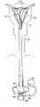
- FIG. 1is a front elevation view of a first embodiment of an ablation device according to the present invention, with the handle shown in cross-section and with the RF applicator head in a closed condition.
- FIG. 2is a front elevation view of the ablation device of FIG. 1 , with the handle shown in cross-section and with the RF applicator head in an open condition.
- FIG. 3is a side elevation view of the ablation device of FIG. 2 .
- FIG. 4is a top plan view of the ablation device of FIG. 2 .
- FIG. 5Ais a front elevation view of the applicator head and a portion of the main body of the ablation device of FIG. 2 , with the main body shown in cross-section.
- FIG. 5Bis a cross-section view of the main body taken along the plane designated 5 B- 5 B in FIG. 5A .
- FIG. 6is a schematic representation of a uterus showing the ablation device of FIG. 1 following insertion of the device into the uterus but prior to retraction of the introducer sheath and activation of the spring members.
- FIG. 7is a schematic representation of a uterus showing the ablation device of FIG. 1 following insertion of the device into the uterus and following the retraction of the introducer sheath and the expansion of the RF applicator head.
- FIG. 8is a cross-section view of the RF applicator head and the distal portion of the main body of the apparatus of FIG. 1 , showing the RF applicator head in the closed condition.
- FIG. 9is a cross-section view of the RF applicator head and the distal portion of the main body of the apparatus of FIG. 1 , showing the configuration of RF applicator head after the sheath has been retracted but before the spring members have been released by proximal movement of the shaft.
- FIG. 10is a cross-section view of the RF applicator head and the distal portion of the main body of the apparatus of FIG. 1 , showing the configuration of RF applicator head after the sheath has been retracted and after the spring members have been released into the fully opened condition.
- FIG. 11is a cross-section view of a distal portion of an RF ablation device similar to FIG. 1 which utilizes an alternative spring member configuration for the RF applicator head.
- FIG. 12is a side elevation view of the distal end of an alternate embodiment of an RF ablation device similar to that of FIG. 1 , which utilizes an RF applicator head having a modified shape.
- FIG. 13is a top plan view of the ablation device of FIG. 12 .
- FIG. 14is a representation of a bleeding vessel illustrating use of the ablation device of FIG. 12 for general bleeding control.
- FIGS. 15 and 16are representations of a uterus illustrating use of the ablation device of FIG. 12 for endometrial ablation.
- FIG. 17is a representation of a prostate gland illustrating use of the ablation device of FIG. 12 for prostate ablation.
- FIG. 18is a cross-section view of target tissue for ablation, showing ablation electrodes in contact with the tissue surface and illustrating energy fields generated during bi-polar ablation.
- FIGS. 19A-19Care cross-section views of target tissue for ablation, showing electrodes in contact with the tissue surface and illustrating how varying active electrode density may be used to vary the ablation depth.
- FIG. 20is a side elevation view, similar to the view of FIG. 2 , showing an ablation device according to the present invention in which the electrode carrying means includes inflatable balloons. For purposes of clarity, the electrodes on the electrode carrying means are not shown.
- FIG. 21is a side elevation view of a second exemplary embodiment of an ablation device according to the present invention, showing the array in the retracted state.
- FIG. 22is a side elevation view of the ablation device of FIG. 21 , showing the array in the deployed state.
- FIG. 23is a top plan view of the applicator head of the apparatus of FIG. 21 .
- FIG. 24is a cross-sectional top view of the encircled region designated 24 in FIG. 23 .
- FIG. 25Ais a perspective view of the electrode array of FIG. 23 .
- FIG. 25Bis a distal end view of the applicator head of FIG. 30A .
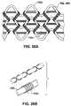
- FIG. 26Ais a plan view of a knit that may be used to form the applicator head.
- FIG. 26Bis a perspective view of a strand of nylon-wrapped spandex of the type that may be used to form the knit of FIG. 26A .
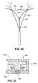
- FIGS. 27A , 27 B, 27 Care top plan views illustrating triangular, parabolic, and rectangular mesh shapes for use as electrode arrays according to the present invention.
- FIG. 28is a perspective view showing the flexures and hypotube of the deflecting mechanism of the applicator head of FIG. 23 .
- FIG. 29is a cross-section view of a flexure taken along the plane designated 29 - 29 in FIG. 23 .
- FIG. 30is a top plan view illustrating the flexure and spring arrangement of an alternative configuration of a deflecting mechanism for an applicator head according to the present invention.
- FIG. 31is a cross-sectional side view of the bobbin portion of the apparatus of FIG. 21 .
- FIG. 32Ais a side elevation view of the handle of the ablation device of FIG. 21 .
- FIG. 32Bis a top plan view of the handle of the ablation device of FIG. 21 . For clarity, portions of the proximal and distal grips are not shown.
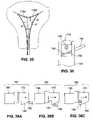
- FIG. 33illustrates placement of the applicator head according to the present invention in a uterine cavity.
- FIG. 34is a side elevation view of the handle of the ablation apparatus of FIG. 21 , showing portions of the apparatus in cross-section.
- FIG. 35is a front elevation view of the upper portion of the proximal handle grip taken along the plane designated 35 - 35 in FIG. 32B .
- FIGS. 36A , 36 B, and 36 Care a series of side elevation views illustrating the heel member as it becomes engaged with the corresponding spring member.
- FIGS. 37A and 37Bare cross-sectional top views of the frame member mounted on the proximal grip section, taken along the plane designated 37 - 37 in FIG. 34 and illustrating one of the load limiting features of the second embodiment.
- FIG. 37Ashows the condition of the compression spring before the heel member moves into abutment with frame member
- FIG. 37Bshows the condition of the spring after the heel member moves into abutment with the frame member.
- an ablation deviceis comprised generally of three major components: RF applicator head 2 , main body 4 , and handle 6 .
- Main body 4includes a shaft 10 .
- the RF applicator head 2includes an electrode carrying means 12 mounted to the distal end of the shaft 10 and an array of electrodes 14 formed on the surface of the electrode carrying means 12 .
- An RF generator 16is electrically connected to the electrodes 14 to provide mono-polar or bipolar RF energy to them.
- Shaft 10is an elongate member having a hollow interior. Shaft 10 is preferably 12 inches long and has a preferred cross-sectional diameter of approximately 4 mm. A collar 13 is formed on the exterior of the shaft 10 at the proximal end. As best shown in FIGS. 6 and 7 , passive spring member 15 are attached to the distal end of the shaft 10 .
- a suction/insufflation tube 17( FIGS. 6-9 ) having a plurality of holes 17 a formed in its distal end.
- An arched active spring member 19is connected between the distal ends of the passive spring members 15 and the distal end of the suction/insufflation tube 17 .
- electrode leads 18 a and 18 bextend through the shaft 10 from distal end 20 to proximal end 22 of the shaft 10 .
- each of the leads 18 a , 18 bis coupled to a respective one of the electrodes 14 .
- the leads 18 a , 18 bare electrically connected to RF generator 16 via an electrical connector 21 .
- the leads 18 a , 18 bcarry RF energy from the RF generator 16 to the electrodes.
- Each of the leads 18 a , 18 bis insulated and carries energy of an opposite polarity than the other lead.
- Electrically insulated sensor leads 23 a , 23 balso extend through the shaft 10 .
- Contact sensors 25 a , 25 bare attached to the distal ends of the sensor leads 23 a , 23 b , respectively and are mounted to the electrode carrying means 12 .
- the sensor leads 23 a , 23 bare coupled by the connector 21 to a monitoring module in the RF generator 16 which measures impedance between the sensors 25 a , 25 b .
- a reference padmay be positioned in contact with the patient and the impedance between one of the sensors and the reference pad measured.
- electrode leads 18 a , 18 b and sensor leads 23 a , 23 bextend through the shaft 10 between the external walls of the tube 17 and the interior walls of the shaft 10 and they are coupled to electrical connector 21 which is preferably mounted to the collar 13 on the shaft 10 .
- Connector 21which is connectable to the RF generator 16 , includes at least four electrical contact rings 21 a - 21 d ( FIGS. 1 and 2 ) which correspond to each of the leads 18 a , 18 b , 23 a , 23 b .
- Rings 21 a , 21 breceive, from the RF generator, RF energy of positive and negative polarity, respectively.
- Rings 21 c , 21 ddeliver signals from the right and left sensors, respectively, to a monitoring module within the RF generator 16 .
- the electrode carrying means 12is attached to the distal end 20 of the shaft 10 .
- a plurality of holes 24may be formed in the portion of the distal end 20 of the shaft which lies within the electrode carrying means 12 .
- the electrode carrying means 12preferably has a shape which approximates the shape of the body organ which is to be ablated.
- the apparatus shown in FIGS. 1 through 11has a bicornual shape which is desirable for intrauterine ablation.
- the electrode carrying means 12 shown in these figuresincludes horn regions 26 which during use are positioned within the cornual regions of the uterus and which therefore extend towards the fallopian tubes.
- Electrode carrying means 12is preferably a sack formed of a material which is non-conductive, which is permeable to moisture and/or which has a tendency to absorb moisture, and which may be compressed to a smaller volume and subsequently released to its natural size upon elimination of compression.
- Examples of preferred materials for the electrode carrying meansinclude open cell sponge, foam, cotton, fabric, or cotton-like material, or any other material having the desired characteristics.
- the electrode carrying meansmay be formed of a metallized fabric.
- the term “pad”may be used interchangeably with the term electrode carrying means to refer to an electrode carrying means formed of any of the above materials or having the listed properties.
- Electrodes 14are preferably attached to the outer surface of the electrode carrying means 12 , such as by deposition or other attachment mechanism.
- the electrodesare preferably made of lengths of silver, gold, platinum, or any other conductive material.
- the electrodesmay be attached to the electrode carrying means 12 by electron beam deposition, or they may be formed into coiled wires and bonded to the electrode carrying member using a flexible adhesive. Naturally, other means of attaching the electrodes, such as sewing them onto the surface of the carrying member, may alternatively be used. If the electrode carrying means 12 is formed of a metallized fabric, an insulating layer may be etched onto the fabric surface, leaving only the electrode regions exposed.
- the spacing between the electrodesi.e. the distance between the centers of adjacent electrodes
- the widths of the electrodesare selected so that ablation will reach predetermined depths within the tissue, particularly when maximum power is delivered through the electrodes (where maximum power is the level at which low impedance, low voltage ablation can be achieved).
- the depth of ablationis also effected by the electrode density (i.e., the percentage of the target tissue area which is in contact with active electrode surfaces) and may be regulated by pre-selecting the amount of this active electrode coverage. For example, the depth of ablation is much greater when the active electrode surface covers more than 10% of the target tissue than it is when the active electrode surfaces covers 1% of the target tissue.
- each bracketed group of low density electrodesis considered to be a single electrode.
- the electrode widths W and spacings Sextend as shown in FIG. 19A .
- the electrodes 14 awhich have more active area in contact with the underlying tissue T, produce a region of ablation A 1 that extends more deeply into the tissue T than the ablation region A 2 produced by the low density electrodes 14 b , even though the electrode spacings and widths are the same for the high and low density electrodes.
- electrode widthshaving spacings with more than 10% active electrode surface coverage, and their resultant ablation depth, based on an ablation area of 6 cm 2 and a power of 20-40 watts, are given on the following table:
- electrode widthshaving spacings with less than 1% active electrode surface coverage, and their resultant ablation depth, based on an ablation area of 6 cm 2 and a power of 20-40 watts, are given on the following table:
- the depth of ablationis significantly less when the active electrode surface coverage is decreased.
- the preferred electrode spacingis approximately 8-10 mm in the horn regions 26 with the active electrode surfaces covering approximately 1% of the target region. Approximately 1-2 mm electrode spacing (with 10% active electrode coverage) is preferred in the cervical region (designated 28 ) and approximately 3-6 mm (with greater than 10% active electrode surface coverage) is preferred in the main body region.
- the RF generator 16may be configured to include a controller which gives the user a choice of which electrodes should be energized during a particular application in order to give the user control of ablation depth. For example, during an application for which deep ablation is desired, the user may elect to have the generator energize every other electrode, to thereby optimize the effective spacing of the electrodes and to decrease the percentage of active electrode surface coverage, as will be described-below with respect to FIG. 18 .
- the electrodes shown in the drawingsare arranged in a particular pattern, it should be appreciated that the electrodes may be arranged in any pattern to provide ablation to desired depths.
- an introducer sheath 32facilitates insertion of the apparatus into, and removal of the apparatus from, the body organ to be ablated.
- the sheath 32is a tubular member which is telescopically slidable over the shaft 10 .
- the sheath 32is slidable between a distal condition, shown in FIG. 6 , in which the electrode carrying means 12 is compressed inside the sheath, and a proximal condition in which the sheath 32 is moved proximally to release the electrode carrying means from inside it ( FIG. 7 ).
- the electrode carrying means 12By compressing the electrode carrying means 12 to a small volume, the electrode carrying means and electrodes can be easily inserted into the body cavity (such as into the uterus via the vaginal opening).
- a handle 34 attached to the sheath 32provides finger holds to allow for manipulation of the sheath 32 .
- Handle 34is slidably mounted on a handle rail 35 which includes a sleeve 33 , a finger cutout 37 , and a pair of spaced rails 35 a , 35 b extending between the sleeve 33 and the finger cutout 37 .
- the shaft 10 and sheath 32slidably extend through the sleeve 33 and between the rails 35 a , 35 b .
- the tube 17also extends through the sleeve 33 and between the rails 35 a , 35 b , and its proximal end is fixed to the handle rail 35 near the finger cutout 37 .
- a compression spring 39is disposed around the proximal most portion of the suction/insufflation tube 17 which lies between the rails 35 a , 35 b .
- One end of the compression spring 39rests against the collar 13 on the shaft 10 , while the opposite end of the compression spring rests against the handle rail 35 .
- the sheath 32is retracted from the electrode carrying means 12 by squeezing the handle 34 towards the finger cutout 37 to slide the sheath 32 in the distal direction.
- the shaft 10(which is attached to the collar 13 ) is forced to slide in the proximal direction, causing compression of the spring 39 against the handle rail 35 .
- the movement of the shaft 10 relative to the suction/insufflation tube 17causes the shaft 10 to pull proximally on the passive spring member 15 .
- Proximal movement of the passive spring member 15in turn pulls against the active spring member 19 , causing it to move to the opened condition shown in FIG. 7 .
- the compression spring 39will push the collar and thus the shaft distally, forcing the RF applicator head to close.
- a locking mechanism(not shown) may be provided to hold the shaft in the fully withdrawn condition to prevent inadvertent closure of the spring members during the ablation procedure.
- the amount by which the springs 15 , 19 are spreadmay be controlled by manipulating the handle 34 to slide the shaft 10 (via collar 13 ), proximally or distally. Such sliding movement of the shaft 10 causes forceps-like movement of the spring members 15 , 19 .
- a flow pathway 36is formed in the handle rail 35 and is fluidly coupled to a suction/insufflation port 38 .
- the proximal end of the suction/insufflation tube 17is fluidly coupled to the flow pathway so that gas fluid may be introduced into, or withdrawn from the suction/insufflation tube 17 via the suction/insufflation port 38 .
- suctionmay be applied to the fluid port 38 using a suction/insufflation unit 40 . This causes water vapor within the uterine cavity to pass through the permeable electrode carrying means 12 , into the suction/insufflation tube 17 via holes 17 a, through the tube 17 , and through the suction/insufflation unit 40 via the port 38 .
- insufflation gassuch as carbon dioxide
- insufflation gasmay be introduced into the suction/insufflation tube 17 via the port 38 .
- the insufflation gastravels through the tube 17 , through the holes 17 a , and into the uterine cavity through the permeable electrode carrying member 12 .
- lumen 42 , 44 , and 46may be formed in the walls of the introducer sheath 32 as shown in FIG. 5B .
- An imaging conduitsuch as a fiberoptic cable 48 , extends through lumen 42 and is coupled via a camera cable 43 to a camera 45 . Images taken from the camera may be displayed on a monitor 56 .
- An illumination fiber 50extends through lumen 44 and is coupled to an illumination source 54 .
- the third lumen 46is an instrument channel through which surgical instruments may be introduced into the uterine cavity, if necessary.
- the electrode carrying means 12may be provide to have additional components inside it that add structural integrity to the electrode carrying means when it is deployed within the body.
- alternative spring members 15 a , 19 amay be attached to the shaft 10 and biased such that, when in a resting state, the spring members are positioned in the fully resting condition shown in FIG. 11 .
- Such spring memberswould spring to the resting condition upon withdrawal of the sheath 32 from the RF applicator head 2 .
- a pair of inflatable balloons 52may be arranged inside the electrode carrying means 12 as shown in FIG. 20 and connected to a tube (not shown) extending through the shaft 10 and into the balloons 52 .
- the balloons 52After insertion of the apparatus into the organ and following retraction of the sheath 32 , the balloons 52 would be inflated by introduction of an inflation medium such as air into the balloons via a port similar to port 38 using an apparatus similar to the suction/insufflation apparatus 40 .
- Structural integritymay also be added to the electrode carrying means through the application of suction to the proximal end 22 of the suction/insufflation tube 17 .
- Application of suction using the suction/insufflation device 40would draw the organ tissue towards the electrode carrying means 12 and thus into better contact with the electrodes 14 .
- FIGS. 12 and 13show an alternative embodiment of an ablation device according to the present invention.
- an electrode carrying means 12 ais provided which has a shape which is generally tubular and thus is not specific to any particular organ shape.
- An ablation device having a general shape such as thismay be used anywhere within the body where ablation or coagulation is needed.
- the alternative embodimentis useful for bleeding control during laparoscopic surgery ( FIG. 14 ), tissue ablation in the prostate gland ( FIG. 17 ), and also intrauterine ablation ( FIGS. 15 and 16 ).
- the deviceis initially configured for use by positioning the introducer sheath 32 distally along the shaft 10 , such that it compresses the electrode carrying means 12 within its walls.
- the electrical connector 21is connected to the RF generator 16 , and the fiberoptic cable 48 and the illumination cable 50 are connected to the illumination source, monitor, and camera, 54 , 56 , 45 .
- the suction/insufflation unit 40is attached to suction/insufflation port 38 on the handle rail 35 .
- the suction/insufflation unit 40is preferably set to deliver carbon dioxide at an insufflation pressure of 20-200 mmHg.
- the distal end of the apparatusis inserted through the vaginal opening V and into the uterus U as shown in FIG. 6 , until the distal end of the introducer sheath 32 contacts the fundus F of the uterus.
- carbon dioxide gasis introduced into the tube 17 via the port 38 , and it enters the uterine cavity, thereby expanding the uterine cavity from a flat triangular shape to a 1-2 cm high triangular cavity.
- the physicianmay observe (using the camera 45 and monitor 56 ) the internal cavities using images detected by a fiberoptic cable 48 inserted through lumen 42 . If, upon observation, the physician determines that a tissue biopsy or other procedure is needed, the required instruments may be inserted into the uterine cavity via the instrument channel 46 .
- the handle 34is withdrawn until it abuts the collar 13 . At this point, the sheath 32 exposes the electrode carrying member 12 but the electrode carrying member 12 is not yet fully expanded (see FIG. 9 ), because the spring members 15 , 19 have not yet been moved to their open condition.
- the handle 34is withdrawn further, causing the shaft 10 to move proximally relative to the suction/insufflation tube 17 , causing the passive spring members 15 to pull tile active spring members 19 , causing them to open into the opened condition shown FIG. 10 .
- the physicianmay confirm proper positioning of the electrode carrying member 12 using the monitor 56 , which displays images from the fiberoptic cable 48 .
- the contact sensors 25 a , 25 bProper positioning of the device and sufficient contact between the electrode carrying member 12 and the endometrium may further be confirmed using the contact sensors 25 a , 25 b .
- the monitoring module of the RF generatormeasures the impedance between these sensors using conventional means. If there is good contact between the sensors and the endometrium, the measured impedance will be approximately 20-180 ohm, depending on the water content of the endometrial lining.
- the sensorsare positioned on the distal portions of the bicornual shaped electrode carrying member 12 , which during use are positioned in the regions within the uterus in which it is most difficult to achieve good contact with the endometrium.
- an indication from the sensors 25 a , 25 b that there is sound contact between the sensors and the endometrial surfaceindicates that good electrode contact has been made with the endometrium.
- insufflationis terminated.
- Approximately 1-5 cc of salinemay be introduced via suction/insufflation tube 17 to initially wet the electrodes and to improve electrode electrical contact with the tissue.
- the suction/insufflation device 40is switched to a suctioning mode. As described above, the application of suction to the RF applicator head 2 via the suction/insufflation tube 17 collapses the uterine cavity onto the RF applicator head 2 and thus assures better contact between the electrodes and the endometrial tissue.
- the deviceis angled into contact with one side of the uterus during the ablation procedure. Once ablation is completed, the device (or a new device) is repositioned in contact with the opposite side and the procedure is repeated. See. FIGS. 15 and 16 .
- each electrodebe energized at a polarity opposite from that of its neighboring electrodes.
- energy field patternsdesignated F 1 , F 2 and F 4 in FIG. 18 , are generated between the electrode sites and thus help to direct the flow of current through the tissue T to form a region of ablation A.
- electrode spacingis increased such by energizing, for example every third or fifth electrode rather than all electrodes, the energy patterns will extend more deeply into the tissue. (See, for example, pattern F 2 which results from energization of electrodes having a non-energized electrode between them, or pattern F 4 which results from energization of electrodes having two non-energized electrodes between them).
- ablation depthmay be controlled as described above by providing low surface density electrodes on areas of the electrode carrying member which will contact tissue areas at which a smaller ablation depth is required (see FIG. 19A ).
- a usermay set the RF generator to energize electrodes which will produce a desired electrode spacing and active electrode area. For example, alternate electrodes may be energized as shown in FIG. 19B , with the first three energized electrodes having positive polarity, the second three having negative polarity, etc.
- the first five electrodesmay be positively energized, and the seventh through eleventh electrodes negatively energized, with the sixth electrode remaining inactivated to provide adequate electrode spacing.
- Tissue which has been ablatedbecomes dehydrated and thus decreases in conductivity. By shunting moisture away from the ablation site and thus preventing liquid build-up, there is no liquid conductor at the ablation area during use of the ablation device of the present invention.
- the impedance at the tissue surfacebecomes sufficiently high to stop or nearly stop the flow of current into the tissue.
- RF ablationthereby stops and thermal ablation does not occur in significant amounts. If the RF generator is equipped with an impedance monitor, a physician utilizing the ablation device can monitor the impedance at the electrodes and will know that ablation has self-terminated once the impedance rises to a certain level and then remains fairly constant.
- thermocouple or other temperature sensormay be inserted to a predetermined depth in the tissue to monitor the temperature of the tissue and terminate the delivery of RF energy or otherwise signal the user when the tissue has reached a desired ablation temperature.
- 1-5 cc of salinecan be introduced via suction/insufflation tube 17 and allowed to sit for a short time to aid separation of the electrode from the tissue surface.
- the suction insufflation device 40is then switched to provide insufflation of carbon dioxide at a pressure of 20-200 mmHg.
- the insufflation pressurehelps to lift the ablated tissue away from the RF applicator head 2 and to thus ease the closing of the RF applicator head.
- the RF applicator head 2is moved to the closed position by sliding the handle 34 in a distal direction to fold the spring members 15 , 19 along the axis of the device and to cause the introducer sheath 32 to slide over the folded RF applicator head.
- the physicianmay visually confirm the sufficiency of the ablation using the monitor 56 .
- the apparatusis removed from the uterine cavity.
- FIGS. 21-37BA second embodiment of an ablation device 100 in accordance with the present invention is shown in FIGS. 21-37B .
- the second embodimentdiffers from the first embodiment primarily in its electrode pattern and in the mechanism used to deploy the electrode applicator head or array.
- aspects of the first and second exemplary embodiments and their methods of operationmay be combined without departing from the scope of the present invention.
- the second embodimentincludes an RF applicator head 102 , a sheath 104 , and a handle 106 .
- the applicator head 102is slidably disposed within the sheath 104 ( FIG. 21 ) during insertion of the device into the uterine cavity, and the handle 106 is subsequently manipulated to cause the applicator head 102 to extend from the distal end of the sheath 104 ( FIG. 22 ) and to expand into contact with body tissue ( FIG. 33 ).
- applicator head 102extends from the distal end of a length of tubing 108 which is slidably disposed within the sheath 104 .
- Applicator head 102includes an external electrode array 102 a and an internal deflecting mechanism 102 b used to expand and tension the array for positioning into contact with the tissue.
- the array 102 a of applicator head 102is formed of a stretchable metallized fabric mesh which is preferably knitted from a nylon and spandex knit plated with gold or other conductive material.
- the knitshown in FIGS. 26A and 26B ) is formed of three monofilaments of nylon 109 a knitted together with single yarns of spandex 109 b .
- Each yarn of spandex 109 bhas a double helix 109 c of five nylon monofilaments coiled around it.
- This knit of elastic (spandex) and inelastic (nylon) yarnsis beneficial for a number of reasons. For example, knitting elastic and relatively inelastic yarns allows the overall deformability of the array to be pre-selected.
- the meshis preferably constructed so as to have greater elasticity in the transverse direction (T) than in the longitudinal direction (L).
- the transverse elasticityis on the order of approximately 300% whereas the longitudinal elasticity is on the order of approximately 100%.
- the large transverse elasticity of the arrayallows it to be used in a wide range of uterine sizes.
- the elastic yarnsprovide the needed elasticity to the array while the relatively inelastic yarns provide relatively non-stretchable members to which the metallization can adhere without cracking during expansion of the array.
- the metallizationadheres to the nylon coiled around the spandex. During expansion of the array, the spandex elongates and the nylon double helix at least partially elongates from-its coiled configuration.
- One process which may be used to apply the gold to the nylon/spandex knitinvolves plating the knit with silver using known processes which involve application of other materials as base layers prior to application of the silver to ensure that the silver will adhere.
- the insulating regions 110are etched onto the silver, and afterwards the gold is plated onto the silver.
- Goldis desirable for the array because of it has a relatively smooth surface, is a very inert material, and has sufficient ductility that it will not crack as the nylon coil elongates during use.
- the meshmay be configured in a variety of shapes, including but not limited to the triangular shape S 1 , parabolic S 2 , and rectangular S 3 shapes shown in FIGS. 27A , 27 B and 27 C, respectively.
- the array 102 awhen in its expanded state, the array 102 a includes a pair of broad faces 1 12 spaced apart from one another. Narrower side faces 114 extend between the broad faces 112 along the sides of the applicator head 102 , and a distal face 116 extends between the broad faces 112 at the distal end of the applicator head 102 .
- Insulating regions 110are formed on the applicator head to divide the mesh into electrode regions.
- the insulated regions 110are preferably formed using etching techniques to remove the conductive metal from the mesh, although alternate methods may also be used, such as by knitting conductive and non-conductive materials together to form the array.
- the arraymay be divided by the insulated regions 110 into a variety of electrode configurations.
- the insulating regions 110divide the applicator head into four electrodes 118 a - 118 d by creating two electrodes on each of the broad faces 112 .
- insulating regions 110are placed longitudinally along each of the broad faces 112 as well as along the length of each of the faces 114 , 116 .
- the electrodes 118 a - 118 dare used for ablation and, if desired, to measure tissue impedance during use.
- Deflecting mechanism 102 b and its deployment structureis enclosed within electrode array 102 a .
- external hypotube 120extends from tubing 108 and an internal hypotube 122 is slidably and co-axially disposed within hypotube 120 .
- Flexures 124extend from the tubing 108 on opposite sides of external hypotube 120 .
- a plurality of longitudinally spaced apertures 126are formed in each flexure 124 . During use, apertures 126 allow moisture to pass through the flexures and to be drawn into exposed distal end of hypotube 120 using a vacuum source fluidly coupled to hypotube 120 .
- Each flexure 124preferably includes conductive regions that are electrically coupled to the array 102 a for delivery of RF energy to the body tissue.
- strips 128 of copper tape or other conductive materialextend along opposite surfaces of each flexure 124 .
- Each strip 128is electrically insulated from the other strip 128 by a non-conductive coating on the flexure.
- Conductor leads(not shown) are electrically coupled to the strips 128 and extend through tubing 108 ( FIG. 23 ) to an electrical cord 130 ( FIG. 21 ) which is attachable to the RF generator.
- one strip 128 on each conductoris electrically coupled via the conductor leads to one terminal on the RF generator while the other strip is electrically coupled to the opposite terminal, thus causing the array on the applicator head to have regions of alternating positive and negative polarity.
- the flexuresmay alternatively be formed using a conductive material or a conductively coated material having insulating regions formed thereon to divide the flexure surfaces into multiple conductive regions.
- alternative methodssuch as electrode leads independent of the flexures 124 may instead be used for electrically connecting the electrode array to the source of RF energy.
- Strands of thread 134(which may be nylon) ( FIG. 23 ) are preferably sewn through the array 102 a and around the flexures 124 in order to prevent the conductive regions 128 from slipping out of alignment with the electrodes 118 a - 118 d .
- Alternate methods for maintaining contact between the array 102 a and the conductive regions 128include using tiny bendable barbs extending between the flexures 124 and the array 102 a to hook the array to the conductive regions 128 , or bonding the array to the flexures using an adhesive applied along the insulating regions of the flexures.
- internal flexures 136extend laterally and longitudinally from the exterior surface of hypotube 122 .
- Each internal flexure 136is connected at its distal end to one of the flexures 124 and a transverse ribbon 138 extends between the distal portions of the internal flexures 136 .
- Transverse ribbon 138is preferably pre-shaped such that when in the relaxed condition the ribbon assumes the corrugated configuration shown in FIG. 23 and such that when in a compressed condition it is folded along the plurality of creases 140 that extend along its length.
- Flexures 124 , 136 and ribbon 138are preferably an insulated spring material such as heat treated 17-7 PH stainless steel.
- the deflecting mechanismis preferably configured such that the distal tips of the flexures 124 are sufficiently flexible to prevent tissue puncture during deployment and/or use.
- Such an atraumatic tip designmay be carried out in a number of ways, such as by manufacturing the distal sections 124 a ( FIG. 28 ) of the flexures from a material that is more flexible than the proximal sections 124 b .
- flexures 124may be provided to have proximal sections formed of a material having a modulus of approximately 28 ⁇ 10 6 psi and distal sections having a durometer of approximately 72 D.
- the flexures 124may be joined to the internal flexures 136 at a location more proximal than the distal tips of the flexures 124 , allowing them to move more freely and to adapt to the contour of the surface against which they are positioned (see dashed lines in FIG. 30 ).
- the atraumatic tip designis further beneficial in that it allows the device to more accurately conform to the shape of the uterus in which it is deployed while minimizing the chance of injury.
- the deflecting mechanism formed by the flexures 124 , 136 , and ribbon 138forms the array into the substantially triangular shape shown in FIG. 23 , which is particularly adaptable to most uterine shapes.
- distal and proximal grips 142 , 144 forming handle 106are squeezed towards one another to withdraw the sheath and deploy the applicator head. This action results in relative rearward motion of the hypotube 120 and relative forward motion of the hypotube 122 .
- the relative motion between the hypotubescauses deflection in flexures 124 , 136 which deploys and tensions the electrode array 102 a.
- the ablation deviceincludes a measurement device for easily measuring the uterine width and for displaying the measured width on a gauge 146 ( FIG. 21 ).
- the measurement deviceutilizes non-conductive (e.g. nylon) suturing threads 148 that extend from the hypotube 122 and that have distal ends attached to the distal portion of the deflecting mechanism ( FIG. 23 ).
- threads 148are preferably formed of a single strand 150 threaded through a wire loop 152 and folded over on itself.
- Wire loop 152forms the distal end of an elongate wire 154 which may be formed of stainless steel or other wire.
- wire 154extends through the hypotube 122 and is secured to a rotatable bobbin 156 .
- the rotatable bobbin 156includes a dial face 158 preferably covered in a clear plastic.
- dial face 158includes calibration markings corresponding to an appropriate range of uterine widths.
- the bobbinis disposed within a gauge housing 160 and a corresponding marker line 162 is printed on the gauge housing.
- a torsion spring 164provides rotational resistance to the bobbin 156 .
- Expansion of the applicator head 102 during usepulls threads 148 ( FIG. 23 ) and thus wire 154 ( FIG. 24 ) in a distal direction.
- Wire 154pulls against the bobbin 156 ( FIG. 31 ), causing it to rotate.
- Rotation of the bobbinpositions one of the calibration markings on dial face 158 into alignment with the marker line 162 ( FIG. 32B ) to indicate the distance between the distal tips of flexures 124 and thus the uterine width.
- the uterine width and lengthare preferably input into an RF generator system and used by the system to calculate an appropriate ablation power as will be described below.
- the width as measured by the apparatus of the invention and length as measured by other meansmay be used by the user to calculate the power to be supplied to the array to achieve the desired ablation depth.
- the uterine widthmay alternatively be measured using other means, including by using a strain gauge in combination with an A/D converter to transduce the separation distance of the flexures 124 and to electronically transmit the uterine width to the RF generator.
- a desirable range of ablation depthsincludes approximately 2-3 mm for the cervical os and the cornual regions, and approximately 7-8 mm in the main body of the uterus where the endometrium is substantially thicker.
- the center to center distance d 1 between the electrodes 118 a , 118 bis larger within the region of the array that lies in the main body of the uterus and thus contributes to deeper ablation.
- the center to center distance d 2 between electrodes 118 a , 118 bis smaller towards the cervical canal where it contributes to shallower ablation.
- the shorter center to center distances d 3extend between top and bottom electrodes 118 b , 118 c and 118 a , 118 d and again contribute to shallower ablation.
- the array 102 aexpands to accommodate the size of the uterus in which it is deployed, the dimensions of the array 102 a vary.
- One embodiment of the array 102 aincludes a range of widths of at least approximately 2.5-4.5 cm, a range of lengths of at least approximately 4-6 cm, and a density of approximately 35%-45%.
- the power supplied to the array by the RF generatoris calculated by the RF generator system to accommodate the electrode area required for a particular patient.
- the uterine widthis measured by the applicator head 102 and displayed on gauge 146 .
- the uterine lengthis measured using a sound, which is an instrument conventionally used for that purpose. It should be noted that calibration markings of the type used on a conventional sound device, or other structure for length measurement, may be included on the present invention to allow it to be used for length measurement as well.
- the userenters the measured dimensions into the RF generator system using an input device, and the RF generator system calculates or obtains the appropriate set power from a stored look-up table using the uterine width and length as entered by the user.
- the usermay manually calculate the power setting from the length and width, or s/he may be provided with a table of suggested power settings for various electrode areas (as determined by the measured length and width) and will manually set the power on the RF generator accordingly.
- the handle 106 of the RF ablation deviceincludes a distal grip section 142 and a proximal grip section 144 that are pivotally attached to one another at pivot pin 166 .
- the proximal grip section 144is coupled to the hypotube 122 ( FIG. 23 ) via yoke 168 , overload spring 170 and spring stop 172 , each of which is shown in the section view of FIG. 34 .
- the distal grip section 142is coupled to the external hypotube 120 via male and female couplers 174 , 176 (see FIGS. 32A and 32B ). Squeezing the grip sections 142 , 144 towards one another thus causes relative movement between the external hypotube 120 and the internal hypotube 122 . This relative sliding movement results in deployment of the deflecting mechanism 102 b from the distal end of the sheath and expansion of the array 102 a to its expanded state.
- rack 180is formed on male coupler 174 and calibration markings 182 are printed adjacent the rack 180 .
- the calibration markings 182correspond to a variety of uterine lengths and may include lengths ranging from, for example, 4.0 to 6.0 cm in 0.5 cm increments.
- a sliding collar 184is slidably disposed on the tubing 108 and is slidable over male coupler 174 .
- Sliding collar 184includes a rotating collar 186 and a female coupler 176 that includes a wedge-shaped heel 188 .
- a locking spring member 190extends across an aperture 192 formed in the proximal grip 144 in alignment with the heel 188 .
- the heel 188passes into the aperture 192 . Its inclined lower surface gradually depresses the spring member 190 as the heel moves further into the aperture 192 . See FIGS. 36A and 36B . After passing completely over the spring member, the heel moves out of contact with the spring member. The spring member snaps upwardly thereby engaging the heel in the locked position. See FIG. 36C .
- a release lever 194( FIG. 35 ) is attached to the free end of the spring member 190 . To disengage the spring lock, release lever 194 is depressed to lower spring member 190 so that the inclined heel can pass over the spring member and thus out of the aperture 192 .
- sliding collar 184is configured to allow the user to limit longitudinal extension of the array 102 a to a distance commensurate with a patient's predetermined uterine length. It does so by allowing the user to adjust the relative longitudinal position of male coupler 174 relative to the female coupler 176 using the rotating collar 186 to lock and unlock the female coupler from the rack 180 and the male coupler 174 . Locking the female coupler to the rack 180 and male coupler 174 will limit extension of the array to approximately the predetermined uterine length, as shown on the calibration markings 182 .
- the userpositions sliding collar 184 adjacent to calibration marks 182 corresponding to the measured uterine length (e.g. 4.5 cm). Afterwards, the user rotates the collar section 186 to engage its internally positioned teeth with the rack 180 . This locks the longitudinal position of the heel 188 such that it will engage with the spring member 190 on the proximal grip when the array has been exposed to the length set by the sliding collar.
- the handle 106includes a pair of spring assemblies which facilitate controlled deployment and stowage of the array 102 a .
- One of the spring assembliescontrols movement of the grips 142 , 144 to automatically stow the array 102 a into the sheath 104 when the user stops squeezing the grips 142 , 144 towards one another.
- the other of the spring assembliescontrols the transverse movement of the spring flexures 124 to the expanded condition by limiting the maximum load that can be applied to the deployment mechanism 102 b.
- FIG. 34shows the distal and proximal grips 142 and 144 in partial cross-section.
- the first spring assembly for controlled stowageincludes a handle return mandrel 196 that is slidably disposed within the proximal grip 144 .
- a compression spring 198surrounds a portion of the return mandrel 196 , and a retaining ring 200 is attached to the mandrel 196 above the spring 198 .
- a spring stop 202is disposed between the spring 198 and the retaining ring.
- the lowermost end of the return mandrel 196is pivotally engaged by a coupling member 204 on distal grip 142 . Relative movement of the grips 142 , 144 towards one another causes the coupling member 204 to pull the return member downwardly with the proximal grip 144 as indicated by arrows. Downward movement of the mandrel 196 causes its retaining ring 200 and spring stop 202 to bear downwardly against the compression spring 198 , thereby providing a movement which acts to rotate the grips 142 , 144 away from one another.
- the second spring assembly for controlling array deploymentis designed to control separation of the flexures. It includes a frame member 178 disposed over yoke 168 , which is pivotally attached to proximal grip 144 .
- Tubing 108extends from the array 102 a (see FIG. 23 ), through the sheath 104 and is fixed at its proximal end to the frame member 178 .
- Hypotube 122does not terminate at this point but instead extends beyond the proximal end of tubing 108 and through a window 206 in the frame member.
- Its proximal end 208is slidably located within frame member 178 proximally of the window 206 and is fluidly coupled to a vacuum port 210 by fluid channel 212 .
- Hypotube 120terminates within the frame. Its proximal end is fixed within the distal end of the frame.
- a spring stop 214is fixed to a section of the hypotube within the window 206 , and a compression spring 170 is disposed around the hypotube between the spring stop 172 and yoke 168 . See FIGS. 32B and 34 .
- collar 214is slidably mounted on sheath 104 .
- collar 214can be positioned along sheath 104 to the position measured by-the uterine sound. Once in position, the collar provides visual and tactile feedback to the user to assure the device has been inserted the proper distance.
- the collar 214can be moved distally towards the cervix, making contact with it and creating a pneumatic seal between the sheath and cervix.
- the usermeasures the uterine length using a uterine sound device.
- the usernext positions sliding collar 184 ( FIG. 32B ) adjacent to calibration marks 182 corresponding to the measured uterine length (e.g. 4.5 cm) and rotates the collar section 186 to engage its internally positioned teeth with the rack 180 .
- Thislocks the longitudinal position of the heel 188 ( FIG. 32A ) such that it will engage with the spring member 190 when the array has been exposed to the length set by the sliding collar.
- the distal end of the device 100is inserted into the uterus. Once the distal end of the sheath 104 is within the uterus, grips 142 , 144 are squeezed together to deploy the applicator head 102 from sheath 104 . Grips 142 , 144 are squeezed until heel 188 engages with locking spring member 190 as described with respect to FIGS. 36A through 36C .
- deflecting mechanism 102 bhas deployed the array 102 a into contact with the uterine walls.
- the userreads the uterine width, which as described above is transduced from the separation of the spring flexures, from gauge 146 .
- the measured length and widthare entered into the RF generator system 250 ( FIG. 21 ) and used to calculate the ablation power.
- Vacuum source 252( FIG. 21 ) is activated, causing application of suction to hypotube 122 via suction port 210 . Suction helps to draw uterine tissue into contact with the array 102 .
- Ablation poweris supplied to the electrode array 102 a by the RF generator system 250 .
- the tissueis heated as the RF energy passes from electrodes 118 a - d to the tissue, causing moisture to be released from the tissue.
- the vacuum sourcehelps to draw moisture from the uterine cavity into the hypotube 122 .
- Moisture withdrawalis facilitated by the apertures 121 formed in flexures 124 by preventing moisture from being trapped between the flexures 124 and the lateral walls of the uterus.
- the RF generator 250includes an impedance monitoring module, impedance may be monitored at the electrodes 118 a - d and the generator may be programmed to terminate RF delivery automatically once the impedance rises to a certain level.
- the generator systemmay also or alternatively display the measured impedance and allow the user to terminate RF delivery when desired.
Landscapes
- Health & Medical Sciences (AREA)
- Life Sciences & Earth Sciences (AREA)
- Engineering & Computer Science (AREA)
- Surgery (AREA)
- Animal Behavior & Ethology (AREA)
- General Health & Medical Sciences (AREA)
- Veterinary Medicine (AREA)
- Biomedical Technology (AREA)
- Heart & Thoracic Surgery (AREA)
- Public Health (AREA)
- Pulmonology (AREA)
- Medical Informatics (AREA)
- Molecular Biology (AREA)
- Nuclear Medicine, Radiotherapy & Molecular Imaging (AREA)
- Hematology (AREA)
- Emergency Medicine (AREA)
- Anesthesiology (AREA)
- Otolaryngology (AREA)
- Physics & Mathematics (AREA)
- Plasma & Fusion (AREA)
- Oral & Maxillofacial Surgery (AREA)
- Pathology (AREA)
- Gynecology & Obstetrics (AREA)
- Pregnancy & Childbirth (AREA)
- Reproductive Health (AREA)
- Electromagnetism (AREA)
- Surgical Instruments (AREA)
Abstract
Description
| ELECTRODE WIDTH | SPACING | APPROX. DEPTH | ||
| 1 | mm | 1-2 | mm | 1-3 | mm |
| 1-2.5 | mm | 3-6 | mm | 5-7 | mm |
| 1-4.5 | mm | 8-10 | mm | 8-10 | mm |
| ELECTRODE WIDTH | SPACING | APPROX. DEPTH | ||
| 1 | mm | 1-2 | mm | 0.5-1 | mm |
| 1-2.5 | mm | 3-6 | mm | 2-3 | mm |
| 1-4.5 | mm | 8-10 | mm | 2-3 | mm |
P=L×W×5.5
Where P is the power level in watts, L is the length in centimeters, W is the width in centimeters, and 5.5 is a constant having units of watts per square centimeter.
Claims (20)
Priority Applications (1)
| Application Number | Priority Date | Filing Date | Title |
|---|---|---|---|
| US11/196,025US7512445B2 (en) | 1996-04-12 | 2005-08-03 | Moisture transport system for contact electrocoagulation |
Applications Claiming Priority (5)
| Application Number | Priority Date | Filing Date | Title |
|---|---|---|---|
| US08/632,516US5769880A (en) | 1996-04-12 | 1996-04-12 | Moisture transport system for contact electrocoagulation |
| US8479198P | 1998-05-08 | 1998-05-08 | |
| US09/103,072US6813520B2 (en) | 1996-04-12 | 1998-06-23 | Method for ablating and/or coagulating tissue using moisture transport |
| US10/959,771US7604633B2 (en) | 1996-04-12 | 2004-10-06 | Moisture transport system for contact electrocoagulation |
| US11/196,025US7512445B2 (en) | 1996-04-12 | 2005-08-03 | Moisture transport system for contact electrocoagulation |
Related Parent Applications (1)
| Application Number | Title | Priority Date | Filing Date |
|---|---|---|---|
| US10/959,771DivisionUS7604633B2 (en) | 1996-04-12 | 2004-10-06 | Moisture transport system for contact electrocoagulation |
Publications (2)
| Publication Number | Publication Date |
|---|---|
| US20050267468A1 US20050267468A1 (en) | 2005-12-01 |
| US7512445B2true US7512445B2 (en) | 2009-03-31 |
Family
ID=46303026
Family Applications (6)
| Application Number | Title | Priority Date | Filing Date |
|---|---|---|---|
| US10/959,771Expired - Fee RelatedUS7604633B2 (en) | 1996-04-12 | 2004-10-06 | Moisture transport system for contact electrocoagulation |
| US11/196,025Expired - Fee RelatedUS7512445B2 (en) | 1996-04-12 | 2005-08-03 | Moisture transport system for contact electrocoagulation |
| US12/581,506Expired - Fee RelatedUS8506563B2 (en) | 1996-04-12 | 2009-10-19 | Moisture transport system for contact electrocoagulation |
| US13/962,178Expired - Fee RelatedUS9095348B2 (en) | 1996-04-12 | 2013-08-08 | Moisture transport system for contact electrocoagulation |
| US14/278,741Expired - Fee RelatedUS8998898B2 (en) | 1996-04-12 | 2014-05-15 | Moisture transport system for contact electrocoagulation |
| US14/635,957Expired - Fee RelatedUS9247989B2 (en) | 1996-04-12 | 2015-03-02 | Moisture transport system for contact electrocoagulation |
Family Applications Before (1)
| Application Number | Title | Priority Date | Filing Date |
|---|---|---|---|
| US10/959,771Expired - Fee RelatedUS7604633B2 (en) | 1996-04-12 | 2004-10-06 | Moisture transport system for contact electrocoagulation |
Family Applications After (4)
| Application Number | Title | Priority Date | Filing Date |
|---|---|---|---|
| US12/581,506Expired - Fee RelatedUS8506563B2 (en) | 1996-04-12 | 2009-10-19 | Moisture transport system for contact electrocoagulation |
| US13/962,178Expired - Fee RelatedUS9095348B2 (en) | 1996-04-12 | 2013-08-08 | Moisture transport system for contact electrocoagulation |
| US14/278,741Expired - Fee RelatedUS8998898B2 (en) | 1996-04-12 | 2014-05-15 | Moisture transport system for contact electrocoagulation |
| US14/635,957Expired - Fee RelatedUS9247989B2 (en) | 1996-04-12 | 2015-03-02 | Moisture transport system for contact electrocoagulation |
Country Status (1)
| Country | Link |
|---|---|
| US (6) | US7604633B2 (en) |
Cited By (127)
| Publication number | Priority date | Publication date | Assignee | Title |
|---|---|---|---|---|
| US20080071257A1 (en)* | 2006-09-18 | 2008-03-20 | Cytyc Corporation | Power Ramping During RF Ablation |
| US20100036372A1 (en)* | 1996-04-12 | 2010-02-11 | Csaba Truckai | Moisture transport system for contact electrocoagulation |
| US20100076425A1 (en)* | 2008-09-23 | 2010-03-25 | Carroux Alexander | Urological balloon catheter |
| US20100114089A1 (en)* | 2008-10-21 | 2010-05-06 | Hermes Innovations Llc | Endometrial ablation devices and systems |
| US20110112523A1 (en)* | 2009-11-11 | 2011-05-12 | Minerva Surgical, Inc. | Systems, methods and devices for endometrial ablation utilizing radio frequency |
| US20110112433A1 (en)* | 2009-11-11 | 2011-05-12 | Minerva Surgical, Inc. | Methods for evaluating the integrity of a uterine cavity |
| US20110118718A1 (en)* | 2009-11-13 | 2011-05-19 | Minerva Surgical, Inc. | Methods and systems for endometrial ablation utilizing radio frequency |
| US8197476B2 (en) | 2008-10-21 | 2012-06-12 | Hermes Innovations Llc | Tissue ablation systems |
| US8197477B2 (en) | 2008-10-21 | 2012-06-12 | Hermes Innovations Llc | Tissue ablation methods |
| US8372068B2 (en) | 2008-10-21 | 2013-02-12 | Hermes Innovations, LLC | Tissue ablation systems |
| US8529562B2 (en) | 2009-11-13 | 2013-09-10 | Minerva Surgical, Inc | Systems and methods for endometrial ablation |
| US8540708B2 (en) | 2008-10-21 | 2013-09-24 | Hermes Innovations Llc | Endometrial ablation method |
| US8551082B2 (en) | 1998-05-08 | 2013-10-08 | Cytyc Surgical Products | Radio-frequency generator for powering an ablation device |
| US20140216467A1 (en)* | 2013-02-04 | 2014-08-07 | Hologic, Inc. | Fundus bumper mechanical reference for easier mechanism deployment |
| US8821486B2 (en) | 2009-11-13 | 2014-09-02 | Hermes Innovations, LLC | Tissue ablation systems and methods |
| US8880185B2 (en) | 2010-06-11 | 2014-11-04 | Boston Scientific Scimed, Inc. | Renal denervation and stimulation employing wireless vascular energy transfer arrangement |
| US8939970B2 (en) | 2004-09-10 | 2015-01-27 | Vessix Vascular, Inc. | Tuned RF energy and electrical tissue characterization for selective treatment of target tissues |
| US8951251B2 (en) | 2011-11-08 | 2015-02-10 | Boston Scientific Scimed, Inc. | Ostial renal nerve ablation |
| US8956348B2 (en) | 2010-07-21 | 2015-02-17 | Minerva Surgical, Inc. | Methods and systems for endometrial ablation |
| US8974451B2 (en) | 2010-10-25 | 2015-03-10 | Boston Scientific Scimed, Inc. | Renal nerve ablation using conductive fluid jet and RF energy |
| US9023034B2 (en) | 2010-11-22 | 2015-05-05 | Boston Scientific Scimed, Inc. | Renal ablation electrode with force-activatable conduction apparatus |
| US9028485B2 (en) | 2010-11-15 | 2015-05-12 | Boston Scientific Scimed, Inc. | Self-expanding cooling electrode for renal nerve ablation |
| US9028472B2 (en) | 2011-12-23 | 2015-05-12 | Vessix Vascular, Inc. | Methods and apparatuses for remodeling tissue of or adjacent to a body passage |
| US9050106B2 (en) | 2011-12-29 | 2015-06-09 | Boston Scientific Scimed, Inc. | Off-wall electrode device and methods for nerve modulation |
| US9060761B2 (en) | 2010-11-18 | 2015-06-23 | Boston Scientific Scime, Inc. | Catheter-focused magnetic field induced renal nerve ablation |
| US9079000B2 (en) | 2011-10-18 | 2015-07-14 | Boston Scientific Scimed, Inc. | Integrated crossing balloon catheter |
| US9084609B2 (en) | 2010-07-30 | 2015-07-21 | Boston Scientific Scime, Inc. | Spiral balloon catheter for renal nerve ablation |
| US9089350B2 (en) | 2010-11-16 | 2015-07-28 | Boston Scientific Scimed, Inc. | Renal denervation catheter with RF electrode and integral contrast dye injection arrangement |
| US9119632B2 (en) | 2011-11-21 | 2015-09-01 | Boston Scientific Scimed, Inc. | Deflectable renal nerve ablation catheter |
| US9119600B2 (en) | 2011-11-15 | 2015-09-01 | Boston Scientific Scimed, Inc. | Device and methods for renal nerve modulation monitoring |
| US9125666B2 (en) | 2003-09-12 | 2015-09-08 | Vessix Vascular, Inc. | Selectable eccentric remodeling and/or ablation of atherosclerotic material |
| US9125667B2 (en) | 2004-09-10 | 2015-09-08 | Vessix Vascular, Inc. | System for inducing desirable temperature effects on body tissue |
| US9155589B2 (en) | 2010-07-30 | 2015-10-13 | Boston Scientific Scimed, Inc. | Sequential activation RF electrode set for renal nerve ablation |
| US9162046B2 (en) | 2011-10-18 | 2015-10-20 | Boston Scientific Scimed, Inc. | Deflectable medical devices |
| US9173696B2 (en) | 2012-09-17 | 2015-11-03 | Boston Scientific Scimed, Inc. | Self-positioning electrode system and method for renal nerve modulation |
| US9186210B2 (en) | 2011-10-10 | 2015-11-17 | Boston Scientific Scimed, Inc. | Medical devices including ablation electrodes |
| US9186209B2 (en) | 2011-07-22 | 2015-11-17 | Boston Scientific Scimed, Inc. | Nerve modulation system having helical guide |
| US9192790B2 (en) | 2010-04-14 | 2015-11-24 | Boston Scientific Scimed, Inc. | Focused ultrasonic renal denervation |
| US9192435B2 (en) | 2010-11-22 | 2015-11-24 | Boston Scientific Scimed, Inc. | Renal denervation catheter with cooled RF electrode |
| US9220558B2 (en) | 2010-10-27 | 2015-12-29 | Boston Scientific Scimed, Inc. | RF renal denervation catheter with multiple independent electrodes |
| US9220561B2 (en) | 2011-01-19 | 2015-12-29 | Boston Scientific Scimed, Inc. | Guide-compatible large-electrode catheter for renal nerve ablation with reduced arterial injury |
| US9265969B2 (en) | 2011-12-21 | 2016-02-23 | Cardiac Pacemakers, Inc. | Methods for modulating cell function |
| US9277955B2 (en) | 2010-04-09 | 2016-03-08 | Vessix Vascular, Inc. | Power generating and control apparatus for the treatment of tissue |
| US9297845B2 (en) | 2013-03-15 | 2016-03-29 | Boston Scientific Scimed, Inc. | Medical devices and methods for treatment of hypertension that utilize impedance compensation |
| US9327100B2 (en) | 2008-11-14 | 2016-05-03 | Vessix Vascular, Inc. | Selective drug delivery in a lumen |
| US9326751B2 (en) | 2010-11-17 | 2016-05-03 | Boston Scientific Scimed, Inc. | Catheter guidance of external energy for renal denervation |
| US9358365B2 (en) | 2010-07-30 | 2016-06-07 | Boston Scientific Scimed, Inc. | Precision electrode movement control for renal nerve ablation |
| US9364284B2 (en) | 2011-10-12 | 2016-06-14 | Boston Scientific Scimed, Inc. | Method of making an off-wall spacer cage |
| US9408661B2 (en) | 2010-07-30 | 2016-08-09 | Patrick A. Haverkost | RF electrodes on multiple flexible wires for renal nerve ablation |
| US9420955B2 (en) | 2011-10-11 | 2016-08-23 | Boston Scientific Scimed, Inc. | Intravascular temperature monitoring system and method |
| US9421059B2 (en) | 2010-04-27 | 2016-08-23 | Minerva Surgical, Inc. | Device for endometrial ablation having an expandable seal for a cervical canal |
| US9433760B2 (en) | 2011-12-28 | 2016-09-06 | Boston Scientific Scimed, Inc. | Device and methods for nerve modulation using a novel ablation catheter with polymeric ablative elements |
| US9463062B2 (en) | 2010-07-30 | 2016-10-11 | Boston Scientific Scimed, Inc. | Cooled conductive balloon RF catheter for renal nerve ablation |
| US9486355B2 (en) | 2005-05-03 | 2016-11-08 | Vessix Vascular, Inc. | Selective accumulation of energy with or without knowledge of tissue topography |
| US9510897B2 (en) | 2010-11-05 | 2016-12-06 | Hermes Innovations Llc | RF-electrode surface and method of fabrication |
| US9561068B2 (en) | 2008-10-06 | 2017-02-07 | Virender K. Sharma | Method and apparatus for tissue ablation |
| US9561066B2 (en) | 2008-10-06 | 2017-02-07 | Virender K. Sharma | Method and apparatus for tissue ablation |
| US9561067B2 (en) | 2008-10-06 | 2017-02-07 | Virender K. Sharma | Method and apparatus for tissue ablation |
| US9579030B2 (en) | 2011-07-20 | 2017-02-28 | Boston Scientific Scimed, Inc. | Percutaneous devices and methods to visualize, target and ablate nerves |
| US9649125B2 (en) | 2013-10-15 | 2017-05-16 | Hermes Innovations Llc | Laparoscopic device |
| US9649156B2 (en) | 2010-12-15 | 2017-05-16 | Boston Scientific Scimed, Inc. | Bipolar off-wall electrode device for renal nerve ablation |
| US9662163B2 (en) | 2008-10-21 | 2017-05-30 | Hermes Innovations Llc | Endometrial ablation devices and systems |
| US9668811B2 (en) | 2010-11-16 | 2017-06-06 | Boston Scientific Scimed, Inc. | Minimally invasive access for renal nerve ablation |
| US9687166B2 (en) | 2013-10-14 | 2017-06-27 | Boston Scientific Scimed, Inc. | High resolution cardiac mapping electrode array catheter |
| US9693821B2 (en) | 2013-03-11 | 2017-07-04 | Boston Scientific Scimed, Inc. | Medical devices for modulating nerves |
| US9700365B2 (en) | 2008-10-06 | 2017-07-11 | Santa Anna Tech Llc | Method and apparatus for the ablation of gastrointestinal tissue |
| US9707036B2 (en) | 2013-06-25 | 2017-07-18 | Boston Scientific Scimed, Inc. | Devices and methods for nerve modulation using localized indifferent electrodes |
| US9713730B2 (en) | 2004-09-10 | 2017-07-25 | Boston Scientific Scimed, Inc. | Apparatus and method for treatment of in-stent restenosis |
| US9757193B2 (en) | 2002-04-08 | 2017-09-12 | Medtronic Ardian Luxembourg S.A.R.L. | Balloon catheter apparatus for renal neuromodulation |
| US9770606B2 (en) | 2013-10-15 | 2017-09-26 | Boston Scientific Scimed, Inc. | Ultrasound ablation catheter with cooling infusion and centering basket |
| US9808300B2 (en) | 2006-05-02 | 2017-11-07 | Boston Scientific Scimed, Inc. | Control of arterial smooth muscle tone |
| US9808311B2 (en) | 2013-03-13 | 2017-11-07 | Boston Scientific Scimed, Inc. | Deflectable medical devices |
| US9827040B2 (en) | 2002-04-08 | 2017-11-28 | Medtronic Adrian Luxembourg S.a.r.l. | Methods and apparatus for intravascularly-induced neuromodulation |
| US9827039B2 (en) | 2013-03-15 | 2017-11-28 | Boston Scientific Scimed, Inc. | Methods and apparatuses for remodeling tissue of or adjacent to a body passage |
| US9833283B2 (en) | 2013-07-01 | 2017-12-05 | Boston Scientific Scimed, Inc. | Medical devices for renal nerve ablation |
| US9895194B2 (en) | 2013-09-04 | 2018-02-20 | Boston Scientific Scimed, Inc. | Radio frequency (RF) balloon catheter having flushing and cooling capability |
| US9901394B2 (en) | 2013-04-04 | 2018-02-27 | Hermes Innovations Llc | Medical ablation system and method of making |
| US9907609B2 (en) | 2014-02-04 | 2018-03-06 | Boston Scientific Scimed, Inc. | Alternative placement of thermal sensors on bipolar electrode |
| US9919144B2 (en) | 2011-04-08 | 2018-03-20 | Medtronic Adrian Luxembourg S.a.r.l. | Iontophoresis drug delivery system and method for denervation of the renal sympathetic nerve and iontophoretic drug delivery |
| US9925001B2 (en) | 2013-07-19 | 2018-03-27 | Boston Scientific Scimed, Inc. | Spiral bipolar electrode renal denervation balloon |
| US9943365B2 (en) | 2013-06-21 | 2018-04-17 | Boston Scientific Scimed, Inc. | Renal denervation balloon catheter with ride along electrode support |
| US9956033B2 (en) | 2013-03-11 | 2018-05-01 | Boston Scientific Scimed, Inc. | Medical devices for modulating nerves |
| US9962223B2 (en) | 2013-10-15 | 2018-05-08 | Boston Scientific Scimed, Inc. | Medical device balloon |
| US9974607B2 (en) | 2006-10-18 | 2018-05-22 | Vessix Vascular, Inc. | Inducing desirable temperature effects on body tissue |
| US10022182B2 (en) | 2013-06-21 | 2018-07-17 | Boston Scientific Scimed, Inc. | Medical devices for renal nerve ablation having rotatable shafts |
| US10064697B2 (en) | 2008-10-06 | 2018-09-04 | Santa Anna Tech Llc | Vapor based ablation system for treating various indications |
| US10085799B2 (en) | 2011-10-11 | 2018-10-02 | Boston Scientific Scimed, Inc. | Off-wall electrode device and methods for nerve modulation |
| US10265122B2 (en) | 2013-03-15 | 2019-04-23 | Boston Scientific Scimed, Inc. | Nerve ablation devices and related methods of use |
| US10271898B2 (en) | 2013-10-25 | 2019-04-30 | Boston Scientific Scimed, Inc. | Embedded thermocouple in denervation flex circuit |
| US10321946B2 (en) | 2012-08-24 | 2019-06-18 | Boston Scientific Scimed, Inc. | Renal nerve modulation devices with weeping RF ablation balloons |
| US10342609B2 (en) | 2013-07-22 | 2019-07-09 | Boston Scientific Scimed, Inc. | Medical devices for renal nerve ablation |
| US10398464B2 (en) | 2012-09-21 | 2019-09-03 | Boston Scientific Scimed, Inc. | System for nerve modulation and innocuous thermal gradient nerve block |
| US10413357B2 (en) | 2013-07-11 | 2019-09-17 | Boston Scientific Scimed, Inc. | Medical device with stretchable electrode assemblies |
| US10492856B2 (en) | 2015-01-26 | 2019-12-03 | Hermes Innovations Llc | Surgical fluid management system and method of use |
| US10549127B2 (en) | 2012-09-21 | 2020-02-04 | Boston Scientific Scimed, Inc. | Self-cooling ultrasound ablation catheter |
| US10588682B2 (en) | 2011-04-25 | 2020-03-17 | Medtronic Ardian Luxembourg S.A.R.L. | Apparatus and methods related to constrained deployment of cryogenic balloons for limited cryogenic ablation of vessel walls |
| US10660703B2 (en) | 2012-05-08 | 2020-05-26 | Boston Scientific Scimed, Inc. | Renal nerve modulation devices |
| US10660698B2 (en) | 2013-07-11 | 2020-05-26 | Boston Scientific Scimed, Inc. | Devices and methods for nerve modulation |
| US10675087B2 (en) | 2015-04-29 | 2020-06-09 | Cirrus Technologies Ltd | Medical ablation device and method of use |
| US10695126B2 (en) | 2008-10-06 | 2020-06-30 | Santa Anna Tech Llc | Catheter with a double balloon structure to generate and apply a heated ablative zone to tissue |
| US10695124B2 (en) | 2013-07-22 | 2020-06-30 | Boston Scientific Scimed, Inc. | Renal nerve ablation catheter having twist balloon |
| US10709490B2 (en) | 2014-05-07 | 2020-07-14 | Medtronic Ardian Luxembourg S.A.R.L. | Catheter assemblies comprising a direct heating element for renal neuromodulation and associated systems and methods |
| US10722300B2 (en) | 2013-08-22 | 2020-07-28 | Boston Scientific Scimed, Inc. | Flexible circuit having improved adhesion to a renal nerve modulation balloon |
| US10835305B2 (en) | 2012-10-10 | 2020-11-17 | Boston Scientific Scimed, Inc. | Renal nerve modulation devices and methods |
| US10945786B2 (en) | 2013-10-18 | 2021-03-16 | Boston Scientific Scimed, Inc. | Balloon catheters with flexible conducting wires and related methods of use and manufacture |
| US10952790B2 (en) | 2013-09-13 | 2021-03-23 | Boston Scientific Scimed, Inc. | Ablation balloon with vapor deposited cover layer |
| US11000679B2 (en) | 2014-02-04 | 2021-05-11 | Boston Scientific Scimed, Inc. | Balloon protection and rewrapping devices and related methods of use |
| US11160597B2 (en) | 2010-11-09 | 2021-11-02 | Aegea Medical Inc. | Positioning method and apparatus for delivering vapor to the uterus |
| US11202671B2 (en) | 2014-01-06 | 2021-12-21 | Boston Scientific Scimed, Inc. | Tear resistant flex circuit assembly |
| US11207118B2 (en) | 2007-07-06 | 2021-12-28 | Tsunami Medtech, Llc | Medical system and method of use |
| US11213338B2 (en) | 2007-08-23 | 2022-01-04 | Aegea Medical Inc. | Uterine therapy device and method |
| US11219479B2 (en) | 2014-05-22 | 2022-01-11 | Aegea Medical Inc. | Integrity testing method and apparatus for delivering vapor to the uterus |
| US11241254B2 (en) | 2012-03-15 | 2022-02-08 | Alydia Health, Inc. | Uterine hemorrhage controlling system and method |
| US11246654B2 (en) | 2013-10-14 | 2022-02-15 | Boston Scientific Scimed, Inc. | Flexible renal nerve ablation devices and related methods of use and manufacture |
| US11253311B2 (en) | 2016-04-22 | 2022-02-22 | RELIGN Corporation | Arthroscopic devices and methods |
| US11331140B2 (en) | 2016-05-19 | 2022-05-17 | Aqua Heart, Inc. | Heated vapor ablation systems and methods for treating cardiac conditions |
| US11331037B2 (en) | 2016-02-19 | 2022-05-17 | Aegea Medical Inc. | Methods and apparatus for determining the integrity of a bodily cavity |
| US11497089B2 (en) | 2017-06-20 | 2022-11-08 | Aegea Medical Inc. | Induction coil assembly for uterine ablation and method |
| US11517336B2 (en) | 2016-08-24 | 2022-12-06 | Alydia Health, Inc. | Uterine hemorrhage controlling system and method |
| US11554214B2 (en) | 2019-06-26 | 2023-01-17 | Meditrina, Inc. | Fluid management system |
| US11576718B2 (en) | 2016-01-20 | 2023-02-14 | RELIGN Corporation | Arthroscopic devices and methods |
| US11766291B2 (en) | 2016-07-01 | 2023-09-26 | RELIGN Corporation | Arthroscopic devices and methods |
| US11806066B2 (en) | 2018-06-01 | 2023-11-07 | Santa Anna Tech Llc | Multi-stage vapor-based ablation treatment methods and vapor generation and delivery systems |
| US11849991B2 (en) | 2011-10-07 | 2023-12-26 | Aegea Medical Inc. | Integrity testing method and apparatus for delivering vapor to the uterus |
| US11896282B2 (en) | 2009-11-13 | 2024-02-13 | Hermes Innovations Llc | Tissue ablation systems and method |
| US12076047B2 (en) | 2012-03-15 | 2024-09-03 | Alydia Health, Inc. | Uterine hemorrhage controlling system and method |
| US12364537B2 (en) | 2016-05-02 | 2025-07-22 | Santa Anna Tech Llc | Catheter with a double balloon structure to generate and apply a heated ablative zone to tissue |
Families Citing this family (66)
| Publication number | Priority date | Publication date | Assignee | Title |
|---|---|---|---|---|
| US6953461B2 (en) | 2002-05-16 | 2005-10-11 | Tissuelink Medical, Inc. | Fluid-assisted medical devices, systems and methods |
| ES2306706T3 (en) | 2000-03-06 | 2008-11-16 | Salient Surgical Technologies, Inc. | FLUID SUPPLY SYSTEM AND CONTROLLER FOR ELECTROCHURGICAL DEVICES. |
| US6558385B1 (en) | 2000-09-22 | 2003-05-06 | Tissuelink Medical, Inc. | Fluid-assisted medical device |
| US6689131B2 (en) | 2001-03-08 | 2004-02-10 | Tissuelink Medical, Inc. | Electrosurgical device having a tissue reduction sensor |
| US7811282B2 (en) | 2000-03-06 | 2010-10-12 | Salient Surgical Technologies, Inc. | Fluid-assisted electrosurgical devices, electrosurgical unit with pump and methods of use thereof |
| US8048070B2 (en) | 2000-03-06 | 2011-11-01 | Salient Surgical Technologies, Inc. | Fluid-assisted medical devices, systems and methods |
| US9433457B2 (en) | 2000-12-09 | 2016-09-06 | Tsunami Medtech, Llc | Medical instruments and techniques for thermally-mediated therapies |
| US8444636B2 (en) | 2001-12-07 | 2013-05-21 | Tsunami Medtech, Llc | Medical instrument and method of use |
| AU2002357166A1 (en) | 2001-12-12 | 2003-06-23 | Tissuelink Medical, Inc. | Fluid-assisted medical devices, systems and methods |
| WO2004039416A2 (en) | 2002-10-29 | 2004-05-13 | Tissuelink Medical, Inc. | Fluid-assisted electrosurgical scissors and methods |
| US7727232B1 (en) | 2004-02-04 | 2010-06-01 | Salient Surgical Technologies, Inc. | Fluid-assisted medical devices and methods |
| US7731712B2 (en) | 2004-12-20 | 2010-06-08 | Cytyc Corporation | Method and system for transcervical tubal occlusion |
| US8721534B1 (en)* | 2005-02-11 | 2014-05-13 | James D. Luecke | Speculum assembly |
| US7674260B2 (en)* | 2005-04-28 | 2010-03-09 | Cytyc Corporation | Emergency hemostasis device utilizing energy |
| US7918863B2 (en)* | 2005-06-24 | 2011-04-05 | Conceptus, Inc. | Minimally invasive surgical stabilization devices and methods |
| US8007449B2 (en)* | 2005-12-20 | 2011-08-30 | Cytyc Corporation | Method and apparatus for uterine cavity length measurement |
| US20080071269A1 (en)* | 2006-09-18 | 2008-03-20 | Cytyc Corporation | Curved Endoscopic Medical Device |
| US7846160B2 (en) | 2006-12-21 | 2010-12-07 | Cytyc Corporation | Method and apparatus for sterilization |
| US20080161893A1 (en)* | 2006-12-29 | 2008-07-03 | Saurav Paul | Fabric electrode head |
| US8235983B2 (en) | 2007-07-12 | 2012-08-07 | Asthmatx, Inc. | Systems and methods for delivering energy to passageways in a patient |
| US9924992B2 (en) | 2008-02-20 | 2018-03-27 | Tsunami Medtech, Llc | Medical system and method of use |
| US8721632B2 (en) | 2008-09-09 | 2014-05-13 | Tsunami Medtech, Llc | Methods for delivering energy into a target tissue of a body |
| US8888792B2 (en) | 2008-07-14 | 2014-11-18 | Ethicon Endo-Surgery, Inc. | Tissue apposition clip application devices and methods |
| EP2397087A3 (en)* | 2009-01-30 | 2013-08-14 | Cytyc Corporation | Cervical opening sealing devices |
| US11284931B2 (en) | 2009-02-03 | 2022-03-29 | Tsunami Medtech, Llc | Medical systems and methods for ablating and absorbing tissue |
| US10660697B2 (en)* | 2009-11-10 | 2020-05-26 | Cardea Medsystems (Tianjin) Co., Ltd. | Hollow body cavity ablation apparatus |
| CN102596082B (en)* | 2009-11-10 | 2015-02-18 | 卡尔迪雅(天津)医疗器械有限公司司 | Hollow Body Ablation Device |
| US9028483B2 (en)* | 2009-12-18 | 2015-05-12 | Ethicon Endo-Surgery, Inc. | Surgical instrument comprising an electrode |
| US9161801B2 (en)* | 2009-12-30 | 2015-10-20 | Tsunami Medtech, Llc | Medical system and method of use |
| US8926629B2 (en) | 2010-02-24 | 2015-01-06 | Minerva Surgical, Inc. | Systems and methods for endometrial ablation |
| US20120116378A1 (en)* | 2010-04-26 | 2012-05-10 | Minerva Surgical, Inc. | Endometrial ablation with a device that conforms to symmetric or asymmetric uterine cavities |
| US20120101498A1 (en)* | 2010-04-27 | 2012-04-26 | Minerva Surgical, Inc. | Systems and methods for endometrial ablation |
| WO2012017394A2 (en)* | 2010-08-04 | 2012-02-09 | Nicola Nasser | Fertility preservation device |
| US9943353B2 (en) | 2013-03-15 | 2018-04-17 | Tsunami Medtech, Llc | Medical system and method of use |
| US9259262B2 (en)* | 2010-11-09 | 2016-02-16 | Minerva Surgical, Inc. | Systems and methods for endometrial ablation |
| US20120310046A1 (en)* | 2011-05-31 | 2012-12-06 | Stout Christopher A | Systems for reducing fluid leakage and spray-back from endoscopic medical procedures |
| US9138343B2 (en) | 2011-05-31 | 2015-09-22 | Bayer Healthcare Llc | Tip protector sleeve |
| US9237924B2 (en) | 2011-06-14 | 2016-01-19 | Aerin Medical, Inc. | Methods and devices to treat nasal airways |
| US11304746B2 (en) | 2011-06-14 | 2022-04-19 | Aerin Medical Inc. | Method of treating airway tissue to reduce mucus secretion |
| US10722282B2 (en) | 2011-06-14 | 2020-07-28 | Aerin Medical, Inc. | Methods and devices to treat nasal airways |
| US11033318B2 (en) | 2011-06-14 | 2021-06-15 | Aerin Medical, Inc. | Methods and devices to treat nasal airways |
| US11241271B2 (en) | 2011-06-14 | 2022-02-08 | Aerin Medical Inc. | Methods of treating nasal airways |
| US20240050143A1 (en) | 2011-06-14 | 2024-02-15 | Aerin Medical Inc. | Methods and devices to treat nasal airways |
| US20130269705A1 (en)* | 2012-04-16 | 2013-10-17 | Thomas C. Kochem | Variable stiffness flexure |
| USD714436S1 (en)* | 2012-04-24 | 2014-09-30 | Femasys Inc. | Device for delivering materials |
| US9427255B2 (en) | 2012-05-14 | 2016-08-30 | Ethicon Endo-Surgery, Inc. | Apparatus for introducing a steerable camera assembly into a patient |
| ES2704498T3 (en) | 2012-07-29 | 2019-03-18 | Vvt Medical Ltd | Ablation catheter for ablation of blood vessels and methods for their use |
| US9532901B2 (en) | 2013-02-05 | 2017-01-03 | Mor Research Applications Ltd. | Fertility preservation device |
| US10098527B2 (en) | 2013-02-27 | 2018-10-16 | Ethidcon Endo-Surgery, Inc. | System for performing a minimally invasive surgical procedure |
| US9895192B2 (en)* | 2013-03-13 | 2018-02-20 | Hologic, Inc. | Intrauterine treatment device with articulating array |
| EP2967955A1 (en)* | 2013-03-15 | 2016-01-20 | The Cleveland Clinic Foundation | Gastric plication guide |
| US9974675B2 (en) | 2014-04-04 | 2018-05-22 | W. L. Gore & Associates, Inc. | Delivery and deployment systems for bifurcated stent grafts |
| US20160089172A1 (en)* | 2014-09-30 | 2016-03-31 | Boston Scientific Scimed, Inc. | Devices and methods for applying suction |
| EP3203922B1 (en)* | 2014-10-07 | 2018-04-18 | Hologic, Inc. | Endometrial lining tissue treatment device |
| CN104784764A (en)* | 2015-04-27 | 2015-07-22 | 李亮 | Collecting device for placenta previa cesarean delivery colporrhagia |
| US10111649B2 (en) | 2016-05-20 | 2018-10-30 | Arthrex, Inc. | Surgical instrument |
| CN109561929A (en)* | 2016-06-06 | 2019-04-02 | 纽乌罗有限公司 | Device for far field bipolar ablation |
| US11806071B2 (en) | 2016-12-22 | 2023-11-07 | Aerin Medical Inc. | Soft palate treatment |
| USD880694S1 (en) | 2017-05-01 | 2020-04-07 | Aerin Medical, Inc. | Nasal airway medical instrument |
| US10758219B2 (en)* | 2017-12-14 | 2020-09-01 | Covidien Lp | Laparoscopic tissue manipulation device |
| US11969205B2 (en)* | 2018-05-16 | 2024-04-30 | Minerva Surgical, Inc. | Medical systems for endometrial ablation |
| USD902412S1 (en) | 2018-10-31 | 2020-11-17 | Aerin Medical, Inc. | Electrosurgery console |
| US11918281B2 (en)* | 2020-10-07 | 2024-03-05 | Biosense Webster (Israel) Ltd. | Folding fan catheter with electrodes |
| WO2022086445A1 (en)* | 2020-10-21 | 2022-04-28 | Magnext Life Science Pte. Ltd. | Medical device |
| US12357817B2 (en) | 2021-04-06 | 2025-07-15 | Aerin Medical Inc. | Nasal neuromodulation devices and methods |
| IT202200007262A1 (en)* | 2022-04-12 | 2023-10-12 | Morabito Nicolo | "Bipolar system for the treatment of pathologies of the uterine cervix" |
Citations (107)
| Publication number | Priority date | Publication date | Assignee | Title |
|---|---|---|---|---|
| US552832A (en) | 1896-01-07 | Instrument for treatment of strictures by electrolysis | ||
| US725731A (en) | 1901-08-09 | 1903-04-21 | Samuel H Linn | Cataphoric electrode. |
| DE384246C (en) | 1922-03-04 | 1923-10-31 | Oskar Gleichmann Dr | Medical device for the treatment of female uterine gonorrhea |
| US1620929A (en) | 1925-02-05 | 1927-03-15 | George W Wallerich | Heat-therapy method and means |
| US1827306A (en) | 1925-09-14 | 1931-10-13 | Fischer & Co H G | Electrode |
| FR774550A (en) | 1933-06-16 | 1934-12-08 | Electric device for heat treatment of gonorrhea | |
| US2190383A (en) | 1936-08-29 | 1940-02-13 | Louis B Newman | Therapeutic apparatus |
| US2466042A (en) | 1947-08-26 | 1949-04-05 | Walter J Reich | Internal heat-treatment device |
| US3228398A (en) | 1963-03-12 | 1966-01-11 | Washington Ethical Labs Inc | Vaginal cleanser |
| US3324855A (en) | 1965-01-12 | 1967-06-13 | Henry J Heimlich | Surgical sponge stick |
| US3645265A (en) | 1969-06-25 | 1972-02-29 | Gregory Majzlin | Intrauterine cauterizing device |
| FR2115706A5 (en) | 1970-11-30 | 1972-07-07 | Guerineau Jacques | |
| JPS4867586A (en) | 1971-12-20 | 1973-09-14 | ||
| US3840016A (en) | 1972-03-10 | 1974-10-08 | H Lindemann | Electrocoagulation-bougie for the intrauterine tube sterilization |
| US3877464A (en) | 1972-06-07 | 1975-04-15 | Andrew R Vermes | Intra-uterine biopsy apparatus |
| US3924628A (en) | 1972-12-01 | 1975-12-09 | William Droegemueller | Cyrogenic bladder for necrosing tissue cells |
| US3948270A (en) | 1974-10-15 | 1976-04-06 | Hasson Harrith M | Uterine cannula |
| US3971378A (en) | 1974-12-20 | 1976-07-27 | Ortho Pharmaceutical Corporation | Expansible tampon |
| US4022215A (en) | 1973-12-10 | 1977-05-10 | Benson Jerrel W | Cryosurgical system |
| US4057063A (en) | 1975-04-11 | 1977-11-08 | U.S. Philips Corporation | Device for sterilization by transuterine tube coagulation |
| US4233025A (en) | 1979-03-08 | 1980-11-11 | Larson William A | Hollow cotton roll |
| EP0056178A1 (en) | 1981-01-12 | 1982-07-21 | Mitsubishi Rayon Co., Ltd. | Electrode for living bodies |
| JPS5832756Y2 (en) | 1979-12-05 | 1983-07-21 | 兼三 山本 | Chemical spray nozzle |
| US4415288A (en) | 1981-03-09 | 1983-11-15 | Whitman Medical Corporation | Liquid dispensing device with cartridge-rupturing member |
| US4449528A (en) | 1980-03-20 | 1984-05-22 | University Of Washington | Fast pulse thermal cautery probe and method |
| US4465072A (en) | 1983-02-22 | 1984-08-14 | Taheri Syde A | Needle catheter |
| US4492231A (en) | 1982-09-17 | 1985-01-08 | Auth David C | Non-sticking electrocautery system and forceps |
| US4532924A (en) | 1980-05-13 | 1985-08-06 | American Hospital Supply Corporation | Multipolar electrosurgical device and method |
| US4568326A (en) | 1982-01-27 | 1986-02-04 | Avvari Rangaswamy | Epistaxis sponge |
| US4582057A (en) | 1981-07-20 | 1986-04-15 | Regents Of The University Of Washington | Fast pulse thermal cautery probe |
| US4601698A (en) | 1984-09-17 | 1986-07-22 | Moulding Jr Thomas S | Method of and instrument for injecting a fluid into a uterine cavity and for dispersing the fluid into the fallopian tubes |
| US4628924A (en) | 1983-01-20 | 1986-12-16 | Hugo Cimber | Intrauterine contraceptive device |
| US4662383A (en) | 1982-09-27 | 1987-05-05 | Kureha Kagaku Kogyo Kabushiki Kaisha | Endotract antenna device for hyperthermia |
| US4676258A (en) | 1983-01-24 | 1987-06-30 | Kureha Kagaku Kogyo Kabushiki Kaisha | Device for hyperthermia |
| US4691703A (en) | 1986-04-25 | 1987-09-08 | Board Of Regents, University Of Washington | Thermal cautery system |
| US4765331A (en) | 1987-02-10 | 1988-08-23 | Circon Corporation | Electrosurgical device with treatment arc of less than 360 degrees |
| JPS63318934A (en) | 1987-06-22 | 1988-12-27 | サージカル・レーザー・テクノロジーズ・インコーポレーテッド | Medical laser probe |
| US4832048A (en) | 1987-10-29 | 1989-05-23 | Cordis Corporation | Suction ablation catheter |
| US4865047A (en) | 1988-06-30 | 1989-09-12 | City Of Hope | Hyperthermia applicator |
| US4946440A (en) | 1988-10-05 | 1990-08-07 | Hall John E | Evertible membrane catheter and method of use |
| US4949718A (en) | 1988-09-09 | 1990-08-21 | Gynelab Products | Intrauterine cauterizing apparatus |
| US4960133A (en) | 1988-11-21 | 1990-10-02 | Brunswick Manufacturing Co., Inc. | Esophageal electrode |
| US4961435A (en) | 1987-10-28 | 1990-10-09 | Kureha Kagaku Kogyo Kabushiki Kaishi | High-frequency capacitive heating electrode device |
| US4979948A (en) | 1989-04-13 | 1990-12-25 | Purdue Research Foundation | Method and apparatus for thermally destroying a layer of an organ |
| US4981465A (en) | 1985-01-15 | 1991-01-01 | Coloplast A/S | Disposable closure means for an artificial ostomy opening or an incontinent natural anus |
| US4983177A (en) | 1990-01-03 | 1991-01-08 | Wolf Gerald L | Method and apparatus for reversibly occluding a biological tube |
| US5057106A (en) | 1986-02-27 | 1991-10-15 | Kasevich Associates, Inc. | Microwave balloon angioplasty |
| US5065751A (en) | 1990-01-03 | 1991-11-19 | Wolf Gerald L | Method and apparatus for reversibly occluding a biological tube |
| US5078717A (en) | 1989-04-13 | 1992-01-07 | Everest Medical Corporation | Ablation catheter with selectively deployable electrodes |
| US5084044A (en) | 1989-07-14 | 1992-01-28 | Ciron Corporation | Apparatus for endometrial ablation and method of using same |
| US5147353A (en) | 1990-03-23 | 1992-09-15 | Myriadlase, Inc. | Medical method for applying high energy light and heat for gynecological sterilization procedures |
| US5159925A (en) | 1988-09-09 | 1992-11-03 | Gynelab, Inc. | Cauterizing apparatus and method for laparoscopic cholecystostomy, gallbladder ablation and treatment of benign prostate hypertrophy |
| WO1992019145A3 (en) | 1991-05-03 | 1993-02-04 | Milton H Goldrath | Endometrium coagulating apparatus and surgical method for thermal destruction of the endometrium |
| US5186181A (en) | 1990-07-27 | 1993-02-16 | Cafiero Franconi | Radio frequency thermotherapy |
| US5188122A (en)* | 1989-06-20 | 1993-02-23 | Rocket Of London Limited | Electromagnetic energy generation method |
| US5188602A (en) | 1990-07-12 | 1993-02-23 | Interventional Thermodynamics, Inc. | Method and device for delivering heat to hollow body organs |
| US5248312A (en) | 1992-06-01 | 1993-09-28 | Sensor Electronics, Inc. | Liquid metal-filled balloon |
| WO1994000178A1 (en) | 1992-06-26 | 1994-01-06 | Schneider (Usa) Inc. | Catheter with expandable wire mesh tip |
| US5277201A (en) | 1992-05-01 | 1994-01-11 | Vesta Medical, Inc. | Endometrial ablation apparatus and method |
| EP0584930A1 (en) | 1992-07-31 | 1994-03-02 | Spembly Medical Limited | Cryosurgical ablation |
| WO1994007445A1 (en) | 1992-09-30 | 1994-04-14 | Neuwirth Robert S | Heated balloon medical apparatus with fluid agitating means |
| US5308327A (en) | 1991-11-25 | 1994-05-03 | Advanced Surgical Inc. | Self-deployed inflatable retractor |
| WO1994010948A1 (en) | 1992-11-12 | 1994-05-26 | Neuwirth Robert S | Heated balloon medical apparatus |
| US5334193A (en) | 1992-11-13 | 1994-08-02 | American Cardiac Ablation Co., Inc. | Fluid cooled ablation catheter |
| US5354295A (en) | 1990-03-13 | 1994-10-11 | Target Therapeutics, Inc. | In an endovascular electrolytically detachable wire and tip for the formation of thrombus in arteries, veins, aneurysms, vascular malformations and arteriovenous fistulas |
| WO1994023794A1 (en) | 1993-04-14 | 1994-10-27 | Vesta Medical, Inc. | Method and apparatus for endometrial ablation |
| US5364393A (en) | 1990-07-02 | 1994-11-15 | Heart Technology, Inc. | Tissue dissipative recanalization catheter |
| US5374261A (en) | 1990-07-24 | 1994-12-20 | Yoon; Inbae | Multifunctional devices for use in endoscopic surgical procedures and methods-therefor |
| US5383917A (en) | 1991-07-05 | 1995-01-24 | Jawahar M. Desai | Device and method for multi-phase radio-frequency ablation |
| WO1995004385A1 (en) | 1993-07-27 | 1995-02-09 | Microsulis Limited | Treatment apparatus |
| WO1995005869A1 (en) | 1993-08-24 | 1995-03-02 | Kaare Grue | A probe for a microwave apparatus for clinical and surgical treatment |
| US5395311A (en) | 1990-05-14 | 1995-03-07 | Andrews; Winston A. | Atherectomy catheter |
| WO1995007664A1 (en) | 1993-09-17 | 1995-03-23 | Origin Medsystems, Inc. | Apparatus and method for organ ablation |
| WO1995010326B1 (en) | 1994-10-14 | 1995-05-11 | Bipolar/monopolar endometrial ablation device and method | |
| US5433708A (en) | 1991-05-17 | 1995-07-18 | Innerdyne, Inc. | Method and device for thermal ablation having improved heat transfer |
| US5437629A (en) | 1994-04-14 | 1995-08-01 | Bei Medical Systems | Fluid delivery system for hysteroscopic endometrial ablation |
| US5451204A (en) | 1988-07-22 | 1995-09-19 | Yoon; Inbae | Multifunctional devices for endoscopic surgical procedures |
| US5505730A (en) | 1994-06-24 | 1996-04-09 | Stuart D. Edwards | Thin layer ablation apparatus |
| US5507743A (en) | 1993-11-08 | 1996-04-16 | Zomed International | Coiled RF electrode treatment apparatus |
| US5514091A (en) | 1988-07-22 | 1996-05-07 | Yoon; Inbae | Expandable multifunctional manipulating instruments for various medical procedures |
| US5562703A (en) | 1994-06-14 | 1996-10-08 | Desai; Ashvin H. | Endoscopic surgical instrument |
| US5613950A (en) | 1988-07-22 | 1997-03-25 | Yoon; Inbae | Multifunctional manipulating instrument for various surgical procedures |
| US5667520A (en) | 1990-03-02 | 1997-09-16 | General Surgical Innovations, Inc. | Method of performing balloon dissection |
| US5697882A (en) | 1992-01-07 | 1997-12-16 | Arthrocare Corporation | System and method for electrosurgical cutting and ablation |
| US5702438A (en) | 1995-06-08 | 1997-12-30 | Avitall; Boaz | Expandable recording and ablation catheter system |
| US5716343A (en) | 1989-06-16 | 1998-02-10 | Science Incorporated | Fluid delivery apparatus |
| US5769880A (en) | 1996-04-12 | 1998-06-23 | Novacept | Moisture transport system for contact electrocoagulation |
| US5779698A (en) | 1989-01-18 | 1998-07-14 | Applied Medical Resources Corporation | Angioplasty catheter system and method for making same |
| US5797903A (en) | 1996-04-12 | 1998-08-25 | Ep Technologies, Inc. | Tissue heating and ablation systems and methods using porous electrode structures with electrically conductive surfaces |
| US5800482A (en) | 1996-03-06 | 1998-09-01 | Cardiac Pathways Corporation | Apparatus and method for linear lesion ablation |
| US5846238A (en) | 1996-01-19 | 1998-12-08 | Ep Technologies, Inc. | Expandable-collapsible electrode structures with distal end steering or manipulation |
| US5879348A (en) | 1996-04-12 | 1999-03-09 | Ep Technologies, Inc. | Electrode structures formed from flexible, porous, or woven materials |
| US5888198A (en) | 1992-01-07 | 1999-03-30 | Arthrocare Corporation | Electrosurgical system for resection and ablation of tissue in electrically conductive fluids |
| US5891136A (en) | 1996-01-19 | 1999-04-06 | Ep Technologies, Inc. | Expandable-collapsible mesh electrode structures |
| US5891134A (en)* | 1996-09-24 | 1999-04-06 | Goble; Colin | System and method for applying thermal energy to tissue |
| US5897553A (en) | 1995-11-02 | 1999-04-27 | Medtronic, Inc. | Ball point fluid-assisted electrocautery device |
| US5944715A (en) | 1996-06-20 | 1999-08-31 | Gyrus Medical Limited | Electrosurgical instrument |
| US5954717A (en) | 1997-09-25 | 1999-09-21 | Radiotherapeutics Corporation | Method and system for heating solid tissue |
| US6002968A (en) | 1994-06-24 | 1999-12-14 | Vidacare, Inc. | Uterine treatment apparatus |
| US6123702A (en) | 1998-09-10 | 2000-09-26 | Scimed Life Systems, Inc. | Systems and methods for controlling power in an electrosurgical probe |
| US6159207A (en) | 1997-07-31 | 2000-12-12 | Yoon; Inbae | Protected ablation method and apparatus |
| US6245065B1 (en) | 1998-09-10 | 2001-06-12 | Scimed Life Systems, Inc. | Systems and methods for controlling power in an electrosurgical probe |
| US6293942B1 (en) | 1995-06-23 | 2001-09-25 | Gyrus Medical Limited | Electrosurgical generator method |
| US6315776B1 (en) | 1994-06-24 | 2001-11-13 | Vidacare, Inc. | Thin layer ablation apparatus |
| US6395012B1 (en) | 2000-05-04 | 2002-05-28 | Inbae Yoon | Apparatus and method for delivering and deploying an expandable body member in a uterine cavity |
| US6475213B1 (en) | 1996-01-19 | 2002-11-05 | Ep Technologies, Inc. | Method of ablating body tissue |
| US6554780B1 (en)* | 1999-11-10 | 2003-04-29 | Novacept | System and method for detecting perforations in a body cavity |
Family Cites Families (137)
| Publication number | Priority date | Publication date | Assignee | Title |
|---|---|---|---|---|
| GB189400141A (en) | 1894-01-02 | 1894-07-28 | Frank Wood Haviland | Improvements in Instrument for Delineating the Uterine and other Cavities of the Human Body. |
| US2347195A (en) | 1942-05-25 | 1944-04-25 | Universal Oil Prod Co | Means of contacting fluid reactants |
| CH375263A (en)* | 1961-08-22 | 1964-02-15 | Ehret Charles | Board game |
| US3706307A (en)* | 1970-07-08 | 1972-12-19 | Hollister Inc | Gynecological instrument |
| US3858586A (en) | 1971-03-11 | 1975-01-07 | Martin Lessen | Surgical method and electrode therefor |
| JPS5130154Y2 (en) | 1971-11-26 | 1976-07-29 | ||
| DE2222820A1 (en) | 1972-05-10 | 1973-11-22 | Delma Elektro Med App | ELECTRODE FOR SURFACE COAGULATION |
| US3845771A (en) | 1973-04-24 | 1974-11-05 | W Vise | Electrosurgical glove |
| US3967625A (en) | 1973-07-30 | 1976-07-06 | In Bae Yoon | Device for sterilizing the human female or male by ligation |
| US4185618A (en) | 1976-01-05 | 1980-01-29 | Population Research, Inc. | Promotion of fibrous tissue growth in fallopian tubes for female sterilization |
| US4016867A (en)* | 1976-04-27 | 1977-04-12 | The United States Of America As Represented By The Secretary Of The Department Of Health, Education And Welfare | Uterine caliper and depth gauge |
| US4094320A (en) | 1976-09-09 | 1978-06-13 | Valleylab, Inc. | Electrosurgical safety circuit and method of using same |
| US4204548A (en) | 1977-12-17 | 1980-05-27 | Kurz Karl H | Sound for insertion in the body for the determination of the internal measurements of hollow organs |
| US4158050A (en) | 1978-06-15 | 1979-06-12 | International Fertility Research Programme | Method for effecting female sterilization without surgery |
| US4224951A (en)* | 1978-11-30 | 1980-09-30 | Hasson Harrith M | Gynecological instrument |
| US4347842A (en)* | 1980-02-15 | 1982-09-07 | Mark Beale | Disposable electrical surgical suction tube and instrument |
| US4359454A (en) | 1980-12-16 | 1982-11-16 | World Health Organization | Method and composition containing MCA for female sterilization |
| JPS5832756A (en) | 1981-08-19 | 1983-02-25 | オリンパス光学工業株式会社 | Stone breaking apparatus |
| US4380238A (en) | 1981-08-21 | 1983-04-19 | Institute Straunann | Disposable applicator for mini-laparotomy using a clip method |
| DE3370411D1 (en) | 1982-06-04 | 1987-04-23 | Bbc Brown Boveri & Cie | Hf adaptation transformer |
| US5385544A (en) | 1992-08-12 | 1995-01-31 | Vidamed, Inc. | BPH ablation method and apparatus |
| US4489732A (en)* | 1982-09-20 | 1984-12-25 | Hasson Harrith M | Gynecological instrument |
| DE3330921C1 (en)* | 1983-08-27 | 1985-02-07 | Karl-Heinz Dr.med. 4000 Düsseldorf Kurz | Device for determining the internal mass of hollow organs, especially the uterine cavity |
| US4552557A (en)* | 1983-10-21 | 1985-11-12 | Avvari Rangaswamy | Inflatable uterine hemostat |
| US4606336A (en) | 1984-11-23 | 1986-08-19 | Zeluff James W | Method and apparatus for non-surgically sterilizing female reproductive organs |
| US4739759A (en) | 1985-02-26 | 1988-04-26 | Concept, Inc. | Microprocessor controlled electrosurgical generator |
| US4700701A (en) | 1985-10-23 | 1987-10-20 | Montaldi David H | Sterilization method and apparatus |
| US4869268A (en) | 1987-05-14 | 1989-09-26 | Inbae Yoon | Multi-functional instruments and stretchable ligating and occluding devices |
| US4788966A (en) | 1987-05-14 | 1988-12-06 | Inbae Yoon | Plug for use in a reversible sterilization procedure |
| US4807620A (en) | 1987-05-22 | 1989-02-28 | Advanced Interventional Systems, Inc. | Apparatus for thermal angioplasty |
| US5242437A (en) | 1988-06-10 | 1993-09-07 | Trimedyne Laser Systems, Inc. | Medical device applying localized high intensity light and heat, particularly for destruction of the endometrium |
| US4955377A (en) | 1988-10-28 | 1990-09-11 | Lennox Charles D | Device and method for heating tissue in a patient's body |
| DE3915636C1 (en) | 1989-05-12 | 1990-04-26 | Sass, Wolfgang, Dr. | |
| US5318532A (en) | 1989-10-03 | 1994-06-07 | C. R. Bard, Inc. | Multilumen catheter with variable cross-section lumens |
| US5226908A (en) | 1989-12-05 | 1993-07-13 | Inbae Yoon | Multi-functional instruments and stretchable ligating and occluding devices |
| US5026379A (en) | 1989-12-05 | 1991-06-25 | Inbae Yoon | Multi-functional instruments and stretchable ligating and occluding devices |
| US5217473A (en) | 1989-12-05 | 1993-06-08 | Inbae Yoon | Multi-functional instruments and stretchable ligating and occluding devices |
| US4993984A (en)* | 1990-01-16 | 1991-02-19 | Matarese Anthony G R | Discretionary mosaic art kit |
| DE4001086A1 (en) | 1990-01-17 | 1991-07-18 | Weikl Andreas | Medical treatment catheter widening constricted vessels - has two expandable balloons spaced in axial direction with heat conductive piece between them |
| US5897551A (en) | 1990-03-23 | 1999-04-27 | Myriadlase, Inc. | Medical device for applying high energy light and heat for gynecological sterilization procedures |
| FR2660543B1 (en) | 1990-04-06 | 1998-02-13 | Technomed Int Sa | METHOD FOR AUTOMATICALLY MEASURING THE VOLUME OF A TUMOR, IN PARTICULAR A PROSTATE TUMOR, MEASURING DEVICE, METHOD AND APPARATUS COMPRISING THE SAME. |
| US5109869A (en)* | 1991-01-22 | 1992-05-05 | Baxter International Inc. | Disposable uterine sound device |
| US5160334A (en)* | 1991-04-30 | 1992-11-03 | Utah Medical Products, Inc. | Electrosurgical generator and suction apparatus |
| US5275610A (en)* | 1991-05-13 | 1994-01-04 | Cook Incorporated | Surgical retractors and method of use |
| US5474089A (en) | 1991-06-26 | 1995-12-12 | The United States Of America As Represented By The Secretary Of The Department Of Health And Human Services | Method and device for reversible sterilization |
| US5620481A (en) | 1991-07-05 | 1997-04-15 | Desai; Jawahar M. | Device for multi-phase radio-frequency ablation |
| US5370649A (en) | 1991-08-16 | 1994-12-06 | Myriadlase, Inc. | Laterally reflecting tip for laser transmitting fiber |
| AU658932B2 (en)* | 1991-10-18 | 1995-05-04 | Ethicon Inc. | Endoscopic tissue manipulator |
| AU3128593A (en) | 1991-11-08 | 1993-06-07 | Ep Technologies Inc | Radiofrequency ablation with phase sensitive power detection |
| US5498261A (en) | 1991-12-20 | 1996-03-12 | Advanced Cardiovascular Systems, Inc. | Thermal angioplasty system |
| US5573533A (en) | 1992-04-10 | 1996-11-12 | Medtronic Cardiorhythm | Method and system for radiofrequency ablation of cardiac tissue |
| US5540681A (en) | 1992-04-10 | 1996-07-30 | Medtronic Cardiorhythm | Method and system for radiofrequency ablation of tissue |
| US5562720A (en) | 1992-05-01 | 1996-10-08 | Vesta Medical, Inc. | Bipolar/monopolar endometrial ablation device and method |
| US5263585A (en) | 1992-05-07 | 1993-11-23 | Myriadlase, Inc. | Package for an elongated flexible fiber |
| US5322507A (en) | 1992-08-11 | 1994-06-21 | Myriadlase, Inc. | Endoscope for treatment of prostate |
| US5542916A (en) | 1992-08-12 | 1996-08-06 | Vidamed, Inc. | Dual-channel RF power delivery system |
| US5484400A (en) | 1992-08-12 | 1996-01-16 | Vidamed, Inc. | Dual channel RF delivery system |
| US5357956A (en) | 1992-11-13 | 1994-10-25 | American Cardiac Ablation Co., Inc. | Apparatus and method for monitoring endocardial signal during ablation |
| US5405322A (en) | 1993-08-12 | 1995-04-11 | Boston Scientific Corporation | Method for treating aneurysms with a thermal source |
| US5599346A (en) | 1993-11-08 | 1997-02-04 | Zomed International, Inc. | RF treatment system |
| US5374283A (en) | 1993-12-01 | 1994-12-20 | Flick; A. Bart | Electrical therapeutic apparatus |
| US5505700A (en) | 1994-06-14 | 1996-04-09 | Cordis Corporation | Electro-osmotic infusion catheter |
| US5575788A (en) | 1994-06-24 | 1996-11-19 | Stuart D. Edwards | Thin layer ablation apparatus |
| US6197025B1 (en) | 1994-09-30 | 2001-03-06 | Circon Corporation | Grooved slider electrode for a resectoscope |
| US5885278A (en)* | 1994-10-07 | 1999-03-23 | E.P. Technologies, Inc. | Structures for deploying movable electrode elements |
| US5609598A (en) | 1994-12-30 | 1997-03-11 | Vnus Medical Technologies, Inc. | Method and apparatus for minimally invasive treatment of chronic venous insufficiency |
| SE512002C2 (en)* | 1995-03-01 | 2000-01-10 | Atos Medical Ab | Apparatus for hyperthermia treatment |
| JPH11503035A (en) | 1995-03-14 | 1999-03-23 | ヴィナス メディカル テクノロジーズ インコーポレイテッド | Intravenous pump efficiency test apparatus and method |
| GB9526627D0 (en) | 1995-12-29 | 1996-02-28 | Gyrus Medical Ltd | An electrosurgical instrument and an electrosurgical electrode assembly |
| US5658316A (en) | 1995-07-03 | 1997-08-19 | Automatic Defibrillator, Inc. | Portable defibrillator with disposable power pack |
| US6023638A (en) | 1995-07-28 | 2000-02-08 | Scimed Life Systems, Inc. | System and method for conducting electrophysiological testing using high-voltage energy pulses to stun tissue |
| GB9519982D0 (en) | 1995-09-30 | 1995-12-06 | Magos Adam L | Device |
| US6013076A (en) | 1996-01-09 | 2000-01-11 | Gyrus Medical Limited | Electrosurgical instrument |
| US6152899A (en) | 1996-03-05 | 2000-11-28 | Vnus Medical Technologies, Inc. | Expandable catheter having improved electrode design, and method for applying energy |
| US6036687A (en) | 1996-03-05 | 2000-03-14 | Vnus Medical Technologies, Inc. | Method and apparatus for treating venous insufficiency |
| US6033397A (en) | 1996-03-05 | 2000-03-07 | Vnus Medical Technologies, Inc. | Method and apparatus for treating esophageal varices |
| US6139527A (en) | 1996-03-05 | 2000-10-31 | Vnus Medical Technologies, Inc. | Method and apparatus for treating hemorrhoids |
| WO1997037668A1 (en) | 1996-04-05 | 1997-10-16 | Family Health International | Use of macrolide antibiotics for nonsurgical female sterilization and endometrial ablation |
| US7604633B2 (en) | 1996-04-12 | 2009-10-20 | Cytyc Corporation | Moisture transport system for contact electrocoagulation |
| US6813520B2 (en) | 1996-04-12 | 2004-11-02 | Novacept | Method for ablating and/or coagulating tissue using moisture transport |
| KR20000010722A (en) | 1996-05-03 | 2000-02-25 | 스튜어트 디. 에드워즈 | Apparatus for cosmetically remodeling a body structure |
| US6077257A (en)* | 1996-05-06 | 2000-06-20 | Vidacare, Inc. | Ablation of rectal and other internal body structures |
| US6066139A (en) | 1996-05-14 | 2000-05-23 | Sherwood Services Ag | Apparatus and method for sterilization and embolization |
| GB2317566B (en) | 1996-09-27 | 2000-08-09 | Smiths Industries Plc | Electrosurgery apparatus |
| US6096052A (en) | 1998-07-08 | 2000-08-01 | Ovion, Inc. | Occluding device and method of use |
| US7073504B2 (en) | 1996-12-18 | 2006-07-11 | Ams Research Corporation | Contraceptive system and method of use |
| US20010041900A1 (en) | 1999-12-21 | 2001-11-15 | Ovion, Inc. | Occluding device and method of use |
| WO1998038932A1 (en) | 1997-03-07 | 1998-09-11 | Advanced Closure Systems, Inc. | Resectoscope electrode assembly with simultaneous cutting and coagulation |
| ES2353846T3 (en) | 1997-04-11 | 2011-03-07 | United States Surgical Corporation | APPLIANCE FOR RF ABLATION AND CONTROLLER OF THE SAME. |
| US6231507B1 (en) | 1997-06-02 | 2001-05-15 | Vnus Medical Technologies, Inc. | Pressure tourniquet with ultrasound window and method of use |
| US5954715A (en) | 1997-06-05 | 1999-09-21 | Adiana, Inc. | Method and apparatus for tubal occlusion |
| US5938660A (en) | 1997-06-27 | 1999-08-17 | Daig Corporation | Process and device for the treatment of atrial arrhythmia |
| US6117101A (en) | 1997-07-08 | 2000-09-12 | The Regents Of The University Of California | Circumferential ablation device assembly |
| US5935137A (en) | 1997-07-18 | 1999-08-10 | Gynecare, Inc. | Tubular fallopian sterilization device |
| US6490474B1 (en) | 1997-08-01 | 2002-12-03 | Cardiac Pathways Corporation | System and method for electrode localization using ultrasound |
| US6179832B1 (en) | 1997-09-11 | 2001-01-30 | Vnus Medical Technologies, Inc. | Expandable catheter having two sets of electrodes |
| US6200312B1 (en) | 1997-09-11 | 2001-03-13 | Vnus Medical Technologies, Inc. | Expandable vein ligator catheter having multiple electrode leads |
| US6258084B1 (en) | 1997-09-11 | 2001-07-10 | Vnus Medical Technologies, Inc. | Method for applying energy to biological tissue including the use of tumescent tissue compression |
| US6401719B1 (en) | 1997-09-11 | 2002-06-11 | Vnus Medical Technologies, Inc. | Method of ligating hollow anatomical structures |
| US6293941B1 (en) | 1997-10-06 | 2001-09-25 | Somnus Medical Technologies, Inc. | Method and apparatus for impedance measurement in a multi-channel electro-surgical generator |
| US6071281A (en)* | 1998-05-05 | 2000-06-06 | Ep Technologies, Inc. | Surgical method and apparatus for positioning a diagnostic or therapeutic element within the body and remote power control unit for use with same |
| JP2001522629A (en) | 1997-11-07 | 2001-11-20 | サルヴィアック・リミテッド | Medical insertable occlusive device |
| US6014589A (en) | 1997-11-12 | 2000-01-11 | Vnus Medical Technologies, Inc. | Catheter having expandable electrodes and adjustable stent |
| DE19757720A1 (en) | 1997-12-23 | 1999-06-24 | Sulzer Osypka Gmbh | Method for operating a high-frequency ablation device and device for high-frequency tissue ablation |
| US6047700A (en) | 1998-03-30 | 2000-04-11 | Arthrocare Corporation | Systems and methods for electrosurgical removal of calcified deposits |
| US6171305B1 (en) | 1998-05-05 | 2001-01-09 | Cardiac Pacemakers, Inc. | RF ablation apparatus and method having high output impedance drivers |
| US6508815B1 (en) | 1998-05-08 | 2003-01-21 | Novacept | Radio-frequency generator for powering an ablation device |
| US8551082B2 (en) | 1998-05-08 | 2013-10-08 | Cytyc Surgical Products | Radio-frequency generator for powering an ablation device |
| US6107699A (en) | 1998-05-22 | 2000-08-22 | Scimed Life Systems, Inc. | Power supply for use in electrophysiological apparatus employing high-voltage pulses to render tissue temporarily unresponsive |
| US6428537B1 (en) | 1998-05-22 | 2002-08-06 | Scimed Life Systems, Inc. | Electrophysiological treatment methods and apparatus employing high voltage pulse to render tissue temporarily unresponsive |
| US5997534A (en) | 1998-06-08 | 1999-12-07 | Tu; Hosheng | Medical ablation device and methods thereof |
| US6322559B1 (en) | 1998-07-06 | 2001-11-27 | Vnus Medical Technologies, Inc. | Electrode catheter having coil structure |
| US6238393B1 (en) | 1998-07-07 | 2001-05-29 | Medtronic, Inc. | Method and apparatus for creating a bi-polar virtual electrode used for the ablation of tissue |
| US6296639B1 (en) | 1999-02-12 | 2001-10-02 | Novacept | Apparatuses and methods for interstitial tissue removal |
| US6112123A (en) | 1998-07-28 | 2000-08-29 | Endonetics, Inc. | Device and method for ablation of tissue |
| US6183468B1 (en) | 1998-09-10 | 2001-02-06 | Scimed Life Systems, Inc. | Systems and methods for controlling power in an electrosurgical probe |
| US5979446A (en) | 1998-10-22 | 1999-11-09 | Synergyn Technologies, Inc. | Removable fallopian tube plug and associated methods |
| US6451015B1 (en) | 1998-11-18 | 2002-09-17 | Sherwood Services Ag | Method and system for menu-driven two-dimensional display lesion generator |
| US6254601B1 (en) | 1998-12-08 | 2001-07-03 | Hysterx, Inc. | Methods for occlusion of the uterine arteries |
| US6309384B1 (en) | 1999-02-01 | 2001-10-30 | Adiana, Inc. | Method and apparatus for tubal occlusion |
| ES2316359T3 (en) | 1999-03-22 | 2009-04-16 | Mowycal Lending, Llc | TREATMENT WITH SMALL PEPTIDES TO INDUCE AN ANTIFIBROTIC ACTIVITY. |
| US6258085B1 (en) | 1999-05-11 | 2001-07-10 | Sherwood Services Ag | Electrosurgical return electrode monitor |
| US6231496B1 (en) | 1999-07-07 | 2001-05-15 | Peter J. Wilk | Medical treatment method |
| US6485500B1 (en) | 2000-03-21 | 2002-11-26 | Advanced Cardiovascular Systems, Inc. | Emboli protection system |
| WO2001097897A1 (en) | 2000-06-20 | 2001-12-27 | Starion Instruments, Inc. | Devices and methods for repair of valves in the human body |
| EP1357842B1 (en) | 2001-01-16 | 2010-11-03 | Cytyc Surgical Products | Apparatus and method for treating venous reflux |
| WO2002069821A1 (en) | 2001-03-06 | 2002-09-12 | Thermemed Corp. | Vaporous delivery of thermal energy to tissue sites |
| US8465516B2 (en) | 2001-07-26 | 2013-06-18 | Oregon Health Science University | Bodily lumen closure apparatus and method |
| JP4450622B2 (en) | 2001-09-28 | 2010-04-14 | アンジオ ダイナミクス インコーポレイテッド | Impedance-controlled tissue peeling device and method |
| US6783516B2 (en) | 2001-11-13 | 2004-08-31 | Neosurg Technologies, Inc. | Trocar |
| EP1400182B1 (en) | 2002-04-19 | 2013-03-27 | Ya-Man Ltd | Glove with electrode |
| TW567077B (en) | 2002-12-19 | 2003-12-21 | King S Metal Fiber Technologie | Wearable electrode apparatus and manufacture thereof |
| US20040172051A1 (en) | 2003-02-28 | 2004-09-02 | Sundaram Ravikumar | Method and apparatus for tubal occlusion |
| US6964274B1 (en) | 2004-06-07 | 2005-11-15 | Ethicon, Inc. | Tubal sterilization device having expanding electrodes and method for performing sterilization using the same |
| US7731712B2 (en) | 2004-12-20 | 2010-06-08 | Cytyc Corporation | Method and system for transcervical tubal occlusion |
| US20080071269A1 (en) | 2006-09-18 | 2008-03-20 | Cytyc Corporation | Curved Endoscopic Medical Device |
| US7846160B2 (en) | 2006-12-21 | 2010-12-07 | Cytyc Corporation | Method and apparatus for sterilization |
- 2004
- 2004-10-06USUS10/959,771patent/US7604633B2/ennot_activeExpired - Fee Related
- 2005
- 2005-08-03USUS11/196,025patent/US7512445B2/ennot_activeExpired - Fee Related
- 2009
- 2009-10-19USUS12/581,506patent/US8506563B2/ennot_activeExpired - Fee Related
- 2013
- 2013-08-08USUS13/962,178patent/US9095348B2/ennot_activeExpired - Fee Related
- 2014
- 2014-05-15USUS14/278,741patent/US8998898B2/ennot_activeExpired - Fee Related
- 2015
- 2015-03-02USUS14/635,957patent/US9247989B2/ennot_activeExpired - Fee Related
Patent Citations (120)
| Publication number | Priority date | Publication date | Assignee | Title |
|---|---|---|---|---|
| US552832A (en) | 1896-01-07 | Instrument for treatment of strictures by electrolysis | ||
| US725731A (en) | 1901-08-09 | 1903-04-21 | Samuel H Linn | Cataphoric electrode. |
| DE384246C (en) | 1922-03-04 | 1923-10-31 | Oskar Gleichmann Dr | Medical device for the treatment of female uterine gonorrhea |
| US1620929A (en) | 1925-02-05 | 1927-03-15 | George W Wallerich | Heat-therapy method and means |
| US1827306A (en) | 1925-09-14 | 1931-10-13 | Fischer & Co H G | Electrode |
| FR774550A (en) | 1933-06-16 | 1934-12-08 | Electric device for heat treatment of gonorrhea | |
| US2190383A (en) | 1936-08-29 | 1940-02-13 | Louis B Newman | Therapeutic apparatus |
| US2466042A (en) | 1947-08-26 | 1949-04-05 | Walter J Reich | Internal heat-treatment device |
| US3228398A (en) | 1963-03-12 | 1966-01-11 | Washington Ethical Labs Inc | Vaginal cleanser |
| US3324855A (en) | 1965-01-12 | 1967-06-13 | Henry J Heimlich | Surgical sponge stick |
| US3645265A (en) | 1969-06-25 | 1972-02-29 | Gregory Majzlin | Intrauterine cauterizing device |
| FR2115706A5 (en) | 1970-11-30 | 1972-07-07 | Guerineau Jacques | |
| JPS4867586A (en) | 1971-12-20 | 1973-09-14 | ||
| US3840016A (en) | 1972-03-10 | 1974-10-08 | H Lindemann | Electrocoagulation-bougie for the intrauterine tube sterilization |
| US3877464A (en) | 1972-06-07 | 1975-04-15 | Andrew R Vermes | Intra-uterine biopsy apparatus |
| US3924628A (en) | 1972-12-01 | 1975-12-09 | William Droegemueller | Cyrogenic bladder for necrosing tissue cells |
| US4022215A (en) | 1973-12-10 | 1977-05-10 | Benson Jerrel W | Cryosurgical system |
| US4082096A (en) | 1973-12-10 | 1978-04-04 | Benson Jerrel W | Cryosurgical system |
| US3948270A (en) | 1974-10-15 | 1976-04-06 | Hasson Harrith M | Uterine cannula |
| US3971378A (en) | 1974-12-20 | 1976-07-27 | Ortho Pharmaceutical Corporation | Expansible tampon |
| US4057063A (en) | 1975-04-11 | 1977-11-08 | U.S. Philips Corporation | Device for sterilization by transuterine tube coagulation |
| US4233025A (en) | 1979-03-08 | 1980-11-11 | Larson William A | Hollow cotton roll |
| JPS5832756Y2 (en) | 1979-12-05 | 1983-07-21 | 兼三 山本 | Chemical spray nozzle |
| US4449528A (en) | 1980-03-20 | 1984-05-22 | University Of Washington | Fast pulse thermal cautery probe and method |
| US4532924A (en) | 1980-05-13 | 1985-08-06 | American Hospital Supply Corporation | Multipolar electrosurgical device and method |
| EP0056178A1 (en) | 1981-01-12 | 1982-07-21 | Mitsubishi Rayon Co., Ltd. | Electrode for living bodies |
| US4415288A (en) | 1981-03-09 | 1983-11-15 | Whitman Medical Corporation | Liquid dispensing device with cartridge-rupturing member |
| US4582057A (en) | 1981-07-20 | 1986-04-15 | Regents Of The University Of Washington | Fast pulse thermal cautery probe |
| US4568326A (en) | 1982-01-27 | 1986-02-04 | Avvari Rangaswamy | Epistaxis sponge |
| US4492231A (en) | 1982-09-17 | 1985-01-08 | Auth David C | Non-sticking electrocautery system and forceps |
| US4662383A (en) | 1982-09-27 | 1987-05-05 | Kureha Kagaku Kogyo Kabushiki Kaisha | Endotract antenna device for hyperthermia |
| US4628924A (en) | 1983-01-20 | 1986-12-16 | Hugo Cimber | Intrauterine contraceptive device |
| US4676258A (en) | 1983-01-24 | 1987-06-30 | Kureha Kagaku Kogyo Kabushiki Kaisha | Device for hyperthermia |
| US4465072A (en) | 1983-02-22 | 1984-08-14 | Taheri Syde A | Needle catheter |
| US4601698A (en) | 1984-09-17 | 1986-07-22 | Moulding Jr Thomas S | Method of and instrument for injecting a fluid into a uterine cavity and for dispersing the fluid into the fallopian tubes |
| US4981465A (en) | 1985-01-15 | 1991-01-01 | Coloplast A/S | Disposable closure means for an artificial ostomy opening or an incontinent natural anus |
| US5057106A (en) | 1986-02-27 | 1991-10-15 | Kasevich Associates, Inc. | Microwave balloon angioplasty |
| US4691703A (en) | 1986-04-25 | 1987-09-08 | Board Of Regents, University Of Washington | Thermal cautery system |
| US4765331A (en) | 1987-02-10 | 1988-08-23 | Circon Corporation | Electrosurgical device with treatment arc of less than 360 degrees |
| JPS63318934A (en) | 1987-06-22 | 1988-12-27 | サージカル・レーザー・テクノロジーズ・インコーポレーテッド | Medical laser probe |
| US4961435A (en) | 1987-10-28 | 1990-10-09 | Kureha Kagaku Kogyo Kabushiki Kaishi | High-frequency capacitive heating electrode device |
| US4832048A (en) | 1987-10-29 | 1989-05-23 | Cordis Corporation | Suction ablation catheter |
| US4865047A (en) | 1988-06-30 | 1989-09-12 | City Of Hope | Hyperthermia applicator |
| US5514091A (en) | 1988-07-22 | 1996-05-07 | Yoon; Inbae | Expandable multifunctional manipulating instruments for various medical procedures |
| US5451204A (en) | 1988-07-22 | 1995-09-19 | Yoon; Inbae | Multifunctional devices for endoscopic surgical procedures |
| US5613950A (en) | 1988-07-22 | 1997-03-25 | Yoon; Inbae | Multifunctional manipulating instrument for various surgical procedures |
| US5656013A (en) | 1988-07-22 | 1997-08-12 | Yoon; Inbae | Method of using an expandable multifunctional manipulating instrument for various medical procedures |
| US5730725A (en) | 1988-07-22 | 1998-03-24 | Yoon; Inbae | Expandable multifunctional manipulating instruments for various medical procedures and methods therefor |
| US5159925A (en) | 1988-09-09 | 1992-11-03 | Gynelab, Inc. | Cauterizing apparatus and method for laparoscopic cholecystostomy, gallbladder ablation and treatment of benign prostate hypertrophy |
| US4949718A (en) | 1988-09-09 | 1990-08-21 | Gynelab Products | Intrauterine cauterizing apparatus |
| US4949718B1 (en) | 1988-09-09 | 1998-11-10 | Gynelab Products | Intrauterine cauterizing apparatus |
| US5105808B1 (en) | 1988-09-09 | 1998-07-07 | Gynelab Products | Intrauterine cauterizing method |
| US5105808A (en) | 1988-09-09 | 1992-04-21 | Gynelab Products | Intrauterine cauterizing method |
| US4946440A (en) | 1988-10-05 | 1990-08-07 | Hall John E | Evertible membrane catheter and method of use |
| US4960133A (en) | 1988-11-21 | 1990-10-02 | Brunswick Manufacturing Co., Inc. | Esophageal electrode |
| US5779698A (en) | 1989-01-18 | 1998-07-14 | Applied Medical Resources Corporation | Angioplasty catheter system and method for making same |
| US5078717A (en) | 1989-04-13 | 1992-01-07 | Everest Medical Corporation | Ablation catheter with selectively deployable electrodes |
| US4979948A (en) | 1989-04-13 | 1990-12-25 | Purdue Research Foundation | Method and apparatus for thermally destroying a layer of an organ |
| US5716343A (en) | 1989-06-16 | 1998-02-10 | Science Incorporated | Fluid delivery apparatus |
| US6068613A (en) | 1989-06-16 | 2000-05-30 | Kriesel; Marshall S. | Fluid delivery device |
| US5188122A (en)* | 1989-06-20 | 1993-02-23 | Rocket Of London Limited | Electromagnetic energy generation method |
| US5084044A (en) | 1989-07-14 | 1992-01-28 | Ciron Corporation | Apparatus for endometrial ablation and method of using same |
| US4983177A (en) | 1990-01-03 | 1991-01-08 | Wolf Gerald L | Method and apparatus for reversibly occluding a biological tube |
| US5065751A (en) | 1990-01-03 | 1991-11-19 | Wolf Gerald L | Method and apparatus for reversibly occluding a biological tube |
| US6042596A (en) | 1990-03-02 | 2000-03-28 | General Surgical Innovations, Inc. | Method of performing balloon dissection |
| US5667520A (en) | 1990-03-02 | 1997-09-16 | General Surgical Innovations, Inc. | Method of performing balloon dissection |
| US5354295A (en) | 1990-03-13 | 1994-10-11 | Target Therapeutics, Inc. | In an endovascular electrolytically detachable wire and tip for the formation of thrombus in arteries, veins, aneurysms, vascular malformations and arteriovenous fistulas |
| US5147353A (en) | 1990-03-23 | 1992-09-15 | Myriadlase, Inc. | Medical method for applying high energy light and heat for gynecological sterilization procedures |
| US5395311A (en) | 1990-05-14 | 1995-03-07 | Andrews; Winston A. | Atherectomy catheter |
| US5364393A (en) | 1990-07-02 | 1994-11-15 | Heart Technology, Inc. | Tissue dissipative recanalization catheter |
| US5188602A (en) | 1990-07-12 | 1993-02-23 | Interventional Thermodynamics, Inc. | Method and device for delivering heat to hollow body organs |
| US5374261A (en) | 1990-07-24 | 1994-12-20 | Yoon; Inbae | Multifunctional devices for use in endoscopic surgical procedures and methods-therefor |
| US6277089B1 (en) | 1990-07-24 | 2001-08-21 | Inbae Yoon | Method for ablating portions of the uterus |
| US5186181A (en) | 1990-07-27 | 1993-02-16 | Cafiero Franconi | Radio frequency thermotherapy |
| WO1992019145A3 (en) | 1991-05-03 | 1993-02-04 | Milton H Goldrath | Endometrium coagulating apparatus and surgical method for thermal destruction of the endometrium |
| US5433708A (en) | 1991-05-17 | 1995-07-18 | Innerdyne, Inc. | Method and device for thermal ablation having improved heat transfer |
| US5383917A (en) | 1991-07-05 | 1995-01-24 | Jawahar M. Desai | Device and method for multi-phase radio-frequency ablation |
| US5308327A (en) | 1991-11-25 | 1994-05-03 | Advanced Surgical Inc. | Self-deployed inflatable retractor |
| US5888198A (en) | 1992-01-07 | 1999-03-30 | Arthrocare Corporation | Electrosurgical system for resection and ablation of tissue in electrically conductive fluids |
| US5697882A (en) | 1992-01-07 | 1997-12-16 | Arthrocare Corporation | System and method for electrosurgical cutting and ablation |
| US5871469A (en) | 1992-01-07 | 1999-02-16 | Arthro Care Corporation | System and method for electrosurgical cutting and ablation |
| US5443470A (en) | 1992-05-01 | 1995-08-22 | Vesta Medical, Inc. | Method and apparatus for endometrial ablation |
| US6041260A (en)* | 1992-05-01 | 2000-03-21 | Vesta Medical, Inc. | Method and apparatus for endometrial ablation |
| US5277201A (en) | 1992-05-01 | 1994-01-11 | Vesta Medical, Inc. | Endometrial ablation apparatus and method |
| US5248312A (en) | 1992-06-01 | 1993-09-28 | Sensor Electronics, Inc. | Liquid metal-filled balloon |
| WO1994000178A1 (en) | 1992-06-26 | 1994-01-06 | Schneider (Usa) Inc. | Catheter with expandable wire mesh tip |
| EP0584930A1 (en) | 1992-07-31 | 1994-03-02 | Spembly Medical Limited | Cryosurgical ablation |
| WO1994007445A1 (en) | 1992-09-30 | 1994-04-14 | Neuwirth Robert S | Heated balloon medical apparatus with fluid agitating means |
| WO1994010948A1 (en) | 1992-11-12 | 1994-05-26 | Neuwirth Robert S | Heated balloon medical apparatus |
| US5334193A (en) | 1992-11-13 | 1994-08-02 | American Cardiac Ablation Co., Inc. | Fluid cooled ablation catheter |
| WO1994023794A1 (en) | 1993-04-14 | 1994-10-27 | Vesta Medical, Inc. | Method and apparatus for endometrial ablation |
| WO1995004385A1 (en) | 1993-07-27 | 1995-02-09 | Microsulis Limited | Treatment apparatus |
| WO1995005869A1 (en) | 1993-08-24 | 1995-03-02 | Kaare Grue | A probe for a microwave apparatus for clinical and surgical treatment |
| WO1995007664A1 (en) | 1993-09-17 | 1995-03-23 | Origin Medsystems, Inc. | Apparatus and method for organ ablation |
| US5507743A (en) | 1993-11-08 | 1996-04-16 | Zomed International | Coiled RF electrode treatment apparatus |
| US5437629A (en) | 1994-04-14 | 1995-08-01 | Bei Medical Systems | Fluid delivery system for hysteroscopic endometrial ablation |
| US5562703A (en) | 1994-06-14 | 1996-10-08 | Desai; Ashvin H. | Endoscopic surgical instrument |
| US6002968A (en) | 1994-06-24 | 1999-12-14 | Vidacare, Inc. | Uterine treatment apparatus |
| US5505730A (en) | 1994-06-24 | 1996-04-09 | Stuart D. Edwards | Thin layer ablation apparatus |
| US6315776B1 (en) | 1994-06-24 | 2001-11-13 | Vidacare, Inc. | Thin layer ablation apparatus |
| WO1995010326B1 (en) | 1994-10-14 | 1995-05-11 | Bipolar/monopolar endometrial ablation device and method | |
| US5702438A (en) | 1995-06-08 | 1997-12-30 | Avitall; Boaz | Expandable recording and ablation catheter system |
| US6364877B1 (en) | 1995-06-23 | 2002-04-02 | Gyrus Medical Limited | Electrosurgical generator and system |
| US6293942B1 (en) | 1995-06-23 | 2001-09-25 | Gyrus Medical Limited | Electrosurgical generator method |
| US5897553A (en) | 1995-11-02 | 1999-04-27 | Medtronic, Inc. | Ball point fluid-assisted electrocautery device |
| US5846238A (en) | 1996-01-19 | 1998-12-08 | Ep Technologies, Inc. | Expandable-collapsible electrode structures with distal end steering or manipulation |
| US6475213B1 (en) | 1996-01-19 | 2002-11-05 | Ep Technologies, Inc. | Method of ablating body tissue |
| US5891136A (en) | 1996-01-19 | 1999-04-06 | Ep Technologies, Inc. | Expandable-collapsible mesh electrode structures |
| US5800482A (en) | 1996-03-06 | 1998-09-01 | Cardiac Pathways Corporation | Apparatus and method for linear lesion ablation |
| US5769880A (en) | 1996-04-12 | 1998-06-23 | Novacept | Moisture transport system for contact electrocoagulation |
| US5797903A (en) | 1996-04-12 | 1998-08-25 | Ep Technologies, Inc. | Tissue heating and ablation systems and methods using porous electrode structures with electrically conductive surfaces |
| US5879348A (en) | 1996-04-12 | 1999-03-09 | Ep Technologies, Inc. | Electrode structures formed from flexible, porous, or woven materials |
| US5944715A (en) | 1996-06-20 | 1999-08-31 | Gyrus Medical Limited | Electrosurgical instrument |
| US5891134A (en)* | 1996-09-24 | 1999-04-06 | Goble; Colin | System and method for applying thermal energy to tissue |
| US6159207A (en) | 1997-07-31 | 2000-12-12 | Yoon; Inbae | Protected ablation method and apparatus |
| US5954717A (en) | 1997-09-25 | 1999-09-21 | Radiotherapeutics Corporation | Method and system for heating solid tissue |
| US6123702A (en) | 1998-09-10 | 2000-09-26 | Scimed Life Systems, Inc. | Systems and methods for controlling power in an electrosurgical probe |
| US6245065B1 (en) | 1998-09-10 | 2001-06-12 | Scimed Life Systems, Inc. | Systems and methods for controlling power in an electrosurgical probe |
| US6554780B1 (en)* | 1999-11-10 | 2003-04-29 | Novacept | System and method for detecting perforations in a body cavity |
| US6395012B1 (en) | 2000-05-04 | 2002-05-28 | Inbae Yoon | Apparatus and method for delivering and deploying an expandable body member in a uterine cavity |
Non-Patent Citations (3)
| Title |
|---|
| C. Nibley et al., "Prevention of Impedance Rise During Radiofrequency Current Catheter Ablation by Intra-Electrode Tip Chilling," Circulation [Abstracts From the 67th Scientific Sessions, Dallas Convention Center, Dallas, Texas, Nov. 14-17, 1994], vol. 90, No. 4, Part 2, Oct. 1994, p. 460. |
| D.E. Haines et al. "Observations on Electrode-Tissue Interface Temperature and Effect on Electrical Impedance During Radiofrequency Ablation of Ventricular Myocardium," Circulation, vol. 82, No. 3, Sep. 1990, pp. 1034-1038. |
| W.M. Jackman et al., "Radiofrequency Current Directed Across the Mitral Anulus With a Bipolar Epicardial-Endocardial Catheter Electrode Configuration in Dogs," Circulation, vol. 78, No. 5, Nov. 1988, pp. 1288-1298. |
Cited By (203)
| Publication number | Priority date | Publication date | Assignee | Title |
|---|---|---|---|---|
| US8998898B2 (en) | 1996-04-12 | 2015-04-07 | Cytyc Surgical Products | Moisture transport system for contact electrocoagulation |
| US20100036372A1 (en)* | 1996-04-12 | 2010-02-11 | Csaba Truckai | Moisture transport system for contact electrocoagulation |
| US8506563B2 (en) | 1996-04-12 | 2013-08-13 | Cytyc Surgical Products | Moisture transport system for contact electrocoagulation |
| US9247989B2 (en) | 1996-04-12 | 2016-02-02 | Cytyc Surgical Products | Moisture transport system for contact electrocoagulation |
| US9095348B2 (en) | 1996-04-12 | 2015-08-04 | Cytyc Surgical Products | Moisture transport system for contact electrocoagulation |
| US8551082B2 (en) | 1998-05-08 | 2013-10-08 | Cytyc Surgical Products | Radio-frequency generator for powering an ablation device |
| US9554853B2 (en) | 1998-05-08 | 2017-01-31 | Hologic, Inc. | Radio-frequency generator for powering an ablation device |
| US9827040B2 (en) | 2002-04-08 | 2017-11-28 | Medtronic Adrian Luxembourg S.a.r.l. | Methods and apparatus for intravascularly-induced neuromodulation |
| US9757193B2 (en) | 2002-04-08 | 2017-09-12 | Medtronic Ardian Luxembourg S.A.R.L. | Balloon catheter apparatus for renal neuromodulation |
| US10105180B2 (en) | 2002-04-08 | 2018-10-23 | Medtronic Ardian Luxembourg S.A.R.L. | Methods and apparatus for intravascularly-induced neuromodulation |
| US9827041B2 (en) | 2002-04-08 | 2017-11-28 | Medtronic Ardian Luxembourg S.A.R.L. | Balloon catheter apparatuses for renal denervation |
| US10376311B2 (en) | 2002-04-08 | 2019-08-13 | Medtronic Ardian Luxembourg S.A.R.L. | Methods and apparatus for intravascularly-induced neuromodulation |
| US10420606B2 (en) | 2002-04-08 | 2019-09-24 | Medtronic Ardian Luxembourg S.A.R.L. | Methods and apparatus for performing a non-continuous circumferential treatment of a body lumen |
| US9125666B2 (en) | 2003-09-12 | 2015-09-08 | Vessix Vascular, Inc. | Selectable eccentric remodeling and/or ablation of atherosclerotic material |
| US10188457B2 (en) | 2003-09-12 | 2019-01-29 | Vessix Vascular, Inc. | Selectable eccentric remodeling and/or ablation |
| US9510901B2 (en) | 2003-09-12 | 2016-12-06 | Vessix Vascular, Inc. | Selectable eccentric remodeling and/or ablation |
| US9713730B2 (en) | 2004-09-10 | 2017-07-25 | Boston Scientific Scimed, Inc. | Apparatus and method for treatment of in-stent restenosis |
| US8939970B2 (en) | 2004-09-10 | 2015-01-27 | Vessix Vascular, Inc. | Tuned RF energy and electrical tissue characterization for selective treatment of target tissues |
| US9125667B2 (en) | 2004-09-10 | 2015-09-08 | Vessix Vascular, Inc. | System for inducing desirable temperature effects on body tissue |
| US9486355B2 (en) | 2005-05-03 | 2016-11-08 | Vessix Vascular, Inc. | Selective accumulation of energy with or without knowledge of tissue topography |
| US9808300B2 (en) | 2006-05-02 | 2017-11-07 | Boston Scientific Scimed, Inc. | Control of arterial smooth muscle tone |
| US20080071257A1 (en)* | 2006-09-18 | 2008-03-20 | Cytyc Corporation | Power Ramping During RF Ablation |
| US8486060B2 (en) | 2006-09-18 | 2013-07-16 | Cytyc Corporation | Power ramping during RF ablation |
| US9974607B2 (en) | 2006-10-18 | 2018-05-22 | Vessix Vascular, Inc. | Inducing desirable temperature effects on body tissue |
| US12161392B2 (en) | 2006-10-18 | 2024-12-10 | Boston Scientific Scimed, Inc. | System for inducing desirable temperature effects on body tissue |
| US10213252B2 (en) | 2006-10-18 | 2019-02-26 | Vessix, Inc. | Inducing desirable temperature effects on body tissue |
| US10413356B2 (en) | 2006-10-18 | 2019-09-17 | Boston Scientific Scimed, Inc. | System for inducing desirable temperature effects on body tissue |
| US11207118B2 (en) | 2007-07-06 | 2021-12-28 | Tsunami Medtech, Llc | Medical system and method of use |
| US11213338B2 (en) | 2007-08-23 | 2022-01-04 | Aegea Medical Inc. | Uterine therapy device and method |
| US20100076425A1 (en)* | 2008-09-23 | 2010-03-25 | Carroux Alexander | Urological balloon catheter |
| US11589920B2 (en) | 2008-10-06 | 2023-02-28 | Santa Anna Tech Llc | Catheter with a double balloon structure to generate and apply an ablative zone to tissue |
| US11779430B2 (en) | 2008-10-06 | 2023-10-10 | Santa Anna Tech Llc | Vapor based ablation system for treating uterine bleeding |
| US12310650B2 (en) | 2008-10-06 | 2025-05-27 | Santa Anna Tech Llc | Methods of ablating tissue using time-limited treatment periods |
| US10695126B2 (en) | 2008-10-06 | 2020-06-30 | Santa Anna Tech Llc | Catheter with a double balloon structure to generate and apply a heated ablative zone to tissue |
| US10842549B2 (en) | 2008-10-06 | 2020-11-24 | Santa Anna Tech Llc | Vapor ablation system with a catheter having more than one positioning element and configured to treat pulmonary tissue |
| US10842548B2 (en) | 2008-10-06 | 2020-11-24 | Santa Anna Tech Llc | Vapor ablation system with a catheter having more than one positioning element |
| US10842557B2 (en) | 2008-10-06 | 2020-11-24 | Santa Anna Tech Llc | Vapor ablation system with a catheter having more than one positioning element and configured to treat duodenal tissue |
| US9561068B2 (en) | 2008-10-06 | 2017-02-07 | Virender K. Sharma | Method and apparatus for tissue ablation |
| US11020175B2 (en) | 2008-10-06 | 2021-06-01 | Santa Anna Tech Llc | Methods of ablating tissue using time-limited treatment periods |
| US10064697B2 (en) | 2008-10-06 | 2018-09-04 | Santa Anna Tech Llc | Vapor based ablation system for treating various indications |
| US9561066B2 (en) | 2008-10-06 | 2017-02-07 | Virender K. Sharma | Method and apparatus for tissue ablation |
| US9561067B2 (en) | 2008-10-06 | 2017-02-07 | Virender K. Sharma | Method and apparatus for tissue ablation |
| US9700365B2 (en) | 2008-10-06 | 2017-07-11 | Santa Anna Tech Llc | Method and apparatus for the ablation of gastrointestinal tissue |
| US11813014B2 (en) | 2008-10-06 | 2023-11-14 | Santa Anna Tech Llc | Methods and systems for directed tissue ablation |
| US8372068B2 (en) | 2008-10-21 | 2013-02-12 | Hermes Innovations, LLC | Tissue ablation systems |
| US8998901B2 (en) | 2008-10-21 | 2015-04-07 | Hermes Innovations Llc | Endometrial ablation method |
| US8382753B2 (en) | 2008-10-21 | 2013-02-26 | Hermes Innovations, LLC | Tissue ablation methods |
| US8197477B2 (en) | 2008-10-21 | 2012-06-12 | Hermes Innovations Llc | Tissue ablation methods |
| US8197476B2 (en) | 2008-10-21 | 2012-06-12 | Hermes Innovations Llc | Tissue ablation systems |
| US11911086B2 (en) | 2008-10-21 | 2024-02-27 | Hermes Innovations Llc | Endometrial ablation devices and systems |
| US8500732B2 (en) | 2008-10-21 | 2013-08-06 | Hermes Innovations Llc | Endometrial ablation devices and systems |
| US9662163B2 (en) | 2008-10-21 | 2017-05-30 | Hermes Innovations Llc | Endometrial ablation devices and systems |
| US8540708B2 (en) | 2008-10-21 | 2013-09-24 | Hermes Innovations Llc | Endometrial ablation method |
| US8690873B2 (en) | 2008-10-21 | 2014-04-08 | Hermes Innovations Llc | Endometrial ablation devices and systems |
| US10912606B2 (en) | 2008-10-21 | 2021-02-09 | Hermes Innovations Llc | Endometrial ablation method |
| US12070263B2 (en) | 2008-10-21 | 2024-08-27 | Hermes Innovations Llc | Endometrial ablation method |
| US10617461B2 (en) | 2008-10-21 | 2020-04-14 | Hermes Innovations Llc | Endometrial ablation devices and system |
| US20100114089A1 (en)* | 2008-10-21 | 2010-05-06 | Hermes Innovations Llc | Endometrial ablation devices and systems |
| US9327100B2 (en) | 2008-11-14 | 2016-05-03 | Vessix Vascular, Inc. | Selective drug delivery in a lumen |
| US9775542B2 (en) | 2009-11-11 | 2017-10-03 | Minerva Surgical, Inc. | Apparatus for evaluating the integrity of a uterine cavity |
| US20110112433A1 (en)* | 2009-11-11 | 2011-05-12 | Minerva Surgical, Inc. | Methods for evaluating the integrity of a uterine cavity |
| US8394037B2 (en) | 2009-11-11 | 2013-03-12 | Minerva Surgical, Inc. | Systems and devices for evaluating the integrity of a uterine cavity |
| US8343078B2 (en) | 2009-11-11 | 2013-01-01 | Minerva Surgical, Inc. | Methods for evaluating the integrity of a uterine cavity |
| CN102647943A (en)* | 2009-11-11 | 2012-08-22 | 密涅瓦外科有限公司 | Systems and devices for evaluating the integrity of a uterine cavity |
| CN102647943B (en)* | 2009-11-11 | 2015-09-02 | 密涅瓦外科有限公司 | Evaluate system and the equipment of cavity of uterus integrity |
| US8715278B2 (en) | 2009-11-11 | 2014-05-06 | Minerva Surgical, Inc. | System for endometrial ablation utilizing radio frequency |
| US20110112523A1 (en)* | 2009-11-11 | 2011-05-12 | Minerva Surgical, Inc. | Systems, methods and devices for endometrial ablation utilizing radio frequency |
| US20110112432A1 (en)* | 2009-11-11 | 2011-05-12 | Minerva Surgical, Inc. | Systems and devices for evaluating the integrity of a uterine cavity |
| US11857248B2 (en)* | 2009-11-13 | 2024-01-02 | Minerva Surgical, Inc. | Methods and systems for endometrial ablation utilizing radio frequency |
| US20170231691A1 (en)* | 2009-11-13 | 2017-08-17 | Minerva Surgical, Inc. | Methods and systems for endometrial ablation utilizing radio frequency |
| US20220338920A1 (en)* | 2009-11-13 | 2022-10-27 | Minerva Surgical, Inc. | Methods and systems for endometrial ablation utilizing radio frequency |
| US9289257B2 (en)* | 2009-11-13 | 2016-03-22 | Minerva Surgical, Inc. | Methods and systems for endometrial ablation utilizing radio frequency |
| US12369972B2 (en) | 2009-11-13 | 2025-07-29 | Minerva Surgical, Inc. | Methods and systems for endometrial ablation utilizing radio frequency |
| US11413088B2 (en)* | 2009-11-13 | 2022-08-16 | Minerva Surgical, Inc. | Methods and systems for endometrial ablation utilizing radio frequency |
| US10105176B2 (en)* | 2009-11-13 | 2018-10-23 | Minerva Surgical, Inc. | Methods and systems for endometrial ablation utilizing radio frequency |
| US8529562B2 (en) | 2009-11-13 | 2013-09-10 | Minerva Surgical, Inc | Systems and methods for endometrial ablation |
| US20160166318A1 (en)* | 2009-11-13 | 2016-06-16 | Minerva Surgical, Inc. | Methods and systems for endometrial ablation utilizing radio frequency |
| US9636171B2 (en)* | 2009-11-13 | 2017-05-02 | Minerva Surgical, Inc. | Methods and systems for endometrial ablation utilizing radio frequency |
| US11896282B2 (en) | 2009-11-13 | 2024-02-13 | Hermes Innovations Llc | Tissue ablation systems and method |
| US20110118718A1 (en)* | 2009-11-13 | 2011-05-19 | Minerva Surgical, Inc. | Methods and systems for endometrial ablation utilizing radio frequency |
| US10213246B2 (en) | 2009-11-13 | 2019-02-26 | Hermes Innovations Llc | Tissue ablation systems and method |
| US8821486B2 (en) | 2009-11-13 | 2014-09-02 | Hermes Innovations, LLC | Tissue ablation systems and methods |
| US9277955B2 (en) | 2010-04-09 | 2016-03-08 | Vessix Vascular, Inc. | Power generating and control apparatus for the treatment of tissue |
| US9192790B2 (en) | 2010-04-14 | 2015-11-24 | Boston Scientific Scimed, Inc. | Focused ultrasonic renal denervation |
| US9421059B2 (en) | 2010-04-27 | 2016-08-23 | Minerva Surgical, Inc. | Device for endometrial ablation having an expandable seal for a cervical canal |
| US10052150B2 (en) | 2010-04-27 | 2018-08-21 | Minerva Surgical, Inc. | Device for endometrial ablation having an expandable seal for a cervical canal |
| US8880185B2 (en) | 2010-06-11 | 2014-11-04 | Boston Scientific Scimed, Inc. | Renal denervation and stimulation employing wireless vascular energy transfer arrangement |
| US8956348B2 (en) | 2010-07-21 | 2015-02-17 | Minerva Surgical, Inc. | Methods and systems for endometrial ablation |
| US9408661B2 (en) | 2010-07-30 | 2016-08-09 | Patrick A. Haverkost | RF electrodes on multiple flexible wires for renal nerve ablation |
| US9358365B2 (en) | 2010-07-30 | 2016-06-07 | Boston Scientific Scimed, Inc. | Precision electrode movement control for renal nerve ablation |
| US9463062B2 (en) | 2010-07-30 | 2016-10-11 | Boston Scientific Scimed, Inc. | Cooled conductive balloon RF catheter for renal nerve ablation |
| US9084609B2 (en) | 2010-07-30 | 2015-07-21 | Boston Scientific Scime, Inc. | Spiral balloon catheter for renal nerve ablation |
| US9155589B2 (en) | 2010-07-30 | 2015-10-13 | Boston Scientific Scimed, Inc. | Sequential activation RF electrode set for renal nerve ablation |
| US8974451B2 (en) | 2010-10-25 | 2015-03-10 | Boston Scientific Scimed, Inc. | Renal nerve ablation using conductive fluid jet and RF energy |
| US9220558B2 (en) | 2010-10-27 | 2015-12-29 | Boston Scientific Scimed, Inc. | RF renal denervation catheter with multiple independent electrodes |
| US9510897B2 (en) | 2010-11-05 | 2016-12-06 | Hermes Innovations Llc | RF-electrode surface and method of fabrication |
| US11160597B2 (en) | 2010-11-09 | 2021-11-02 | Aegea Medical Inc. | Positioning method and apparatus for delivering vapor to the uterus |
| US12279802B2 (en) | 2010-11-09 | 2025-04-22 | Coopersurgical, Inc. | Positioning method and apparatus for delivering vapor to the uterus |
| US9848946B2 (en) | 2010-11-15 | 2017-12-26 | Boston Scientific Scimed, Inc. | Self-expanding cooling electrode for renal nerve ablation |
| US9028485B2 (en) | 2010-11-15 | 2015-05-12 | Boston Scientific Scimed, Inc. | Self-expanding cooling electrode for renal nerve ablation |
| US9089350B2 (en) | 2010-11-16 | 2015-07-28 | Boston Scientific Scimed, Inc. | Renal denervation catheter with RF electrode and integral contrast dye injection arrangement |
| US9668811B2 (en) | 2010-11-16 | 2017-06-06 | Boston Scientific Scimed, Inc. | Minimally invasive access for renal nerve ablation |
| US9326751B2 (en) | 2010-11-17 | 2016-05-03 | Boston Scientific Scimed, Inc. | Catheter guidance of external energy for renal denervation |
| US9060761B2 (en) | 2010-11-18 | 2015-06-23 | Boston Scientific Scime, Inc. | Catheter-focused magnetic field induced renal nerve ablation |
| US9192435B2 (en) | 2010-11-22 | 2015-11-24 | Boston Scientific Scimed, Inc. | Renal denervation catheter with cooled RF electrode |
| US9023034B2 (en) | 2010-11-22 | 2015-05-05 | Boston Scientific Scimed, Inc. | Renal ablation electrode with force-activatable conduction apparatus |
| US9649156B2 (en) | 2010-12-15 | 2017-05-16 | Boston Scientific Scimed, Inc. | Bipolar off-wall electrode device for renal nerve ablation |
| US9220561B2 (en) | 2011-01-19 | 2015-12-29 | Boston Scientific Scimed, Inc. | Guide-compatible large-electrode catheter for renal nerve ablation with reduced arterial injury |
| US9919144B2 (en) | 2011-04-08 | 2018-03-20 | Medtronic Adrian Luxembourg S.a.r.l. | Iontophoresis drug delivery system and method for denervation of the renal sympathetic nerve and iontophoretic drug delivery |
| US10588682B2 (en) | 2011-04-25 | 2020-03-17 | Medtronic Ardian Luxembourg S.A.R.L. | Apparatus and methods related to constrained deployment of cryogenic balloons for limited cryogenic ablation of vessel walls |
| US9579030B2 (en) | 2011-07-20 | 2017-02-28 | Boston Scientific Scimed, Inc. | Percutaneous devices and methods to visualize, target and ablate nerves |
| US9186209B2 (en) | 2011-07-22 | 2015-11-17 | Boston Scientific Scimed, Inc. | Nerve modulation system having helical guide |
| US11849991B2 (en) | 2011-10-07 | 2023-12-26 | Aegea Medical Inc. | Integrity testing method and apparatus for delivering vapor to the uterus |
| US9186210B2 (en) | 2011-10-10 | 2015-11-17 | Boston Scientific Scimed, Inc. | Medical devices including ablation electrodes |
| US9420955B2 (en) | 2011-10-11 | 2016-08-23 | Boston Scientific Scimed, Inc. | Intravascular temperature monitoring system and method |
| US10085799B2 (en) | 2011-10-11 | 2018-10-02 | Boston Scientific Scimed, Inc. | Off-wall electrode device and methods for nerve modulation |
| US9364284B2 (en) | 2011-10-12 | 2016-06-14 | Boston Scientific Scimed, Inc. | Method of making an off-wall spacer cage |
| US9162046B2 (en) | 2011-10-18 | 2015-10-20 | Boston Scientific Scimed, Inc. | Deflectable medical devices |
| US9079000B2 (en) | 2011-10-18 | 2015-07-14 | Boston Scientific Scimed, Inc. | Integrated crossing balloon catheter |
| US8951251B2 (en) | 2011-11-08 | 2015-02-10 | Boston Scientific Scimed, Inc. | Ostial renal nerve ablation |
| US9119600B2 (en) | 2011-11-15 | 2015-09-01 | Boston Scientific Scimed, Inc. | Device and methods for renal nerve modulation monitoring |
| US9119632B2 (en) | 2011-11-21 | 2015-09-01 | Boston Scientific Scimed, Inc. | Deflectable renal nerve ablation catheter |
| US9265969B2 (en) | 2011-12-21 | 2016-02-23 | Cardiac Pacemakers, Inc. | Methods for modulating cell function |
| US9028472B2 (en) | 2011-12-23 | 2015-05-12 | Vessix Vascular, Inc. | Methods and apparatuses for remodeling tissue of or adjacent to a body passage |
| US9402684B2 (en) | 2011-12-23 | 2016-08-02 | Boston Scientific Scimed, Inc. | Methods and apparatuses for remodeling tissue of or adjacent to a body passage |
| US9186211B2 (en) | 2011-12-23 | 2015-11-17 | Boston Scientific Scimed, Inc. | Methods and apparatuses for remodeling tissue of or adjacent to a body passage |
| US9592386B2 (en) | 2011-12-23 | 2017-03-14 | Vessix Vascular, Inc. | Methods and apparatuses for remodeling tissue of or adjacent to a body passage |
| US9037259B2 (en) | 2011-12-23 | 2015-05-19 | Vessix Vascular, Inc. | Methods and apparatuses for remodeling tissue of or adjacent to a body passage |
| US9174050B2 (en) | 2011-12-23 | 2015-11-03 | Vessix Vascular, Inc. | Methods and apparatuses for remodeling tissue of or adjacent to a body passage |
| US9072902B2 (en) | 2011-12-23 | 2015-07-07 | Vessix Vascular, Inc. | Methods and apparatuses for remodeling tissue of or adjacent to a body passage |
| US9433760B2 (en) | 2011-12-28 | 2016-09-06 | Boston Scientific Scimed, Inc. | Device and methods for nerve modulation using a novel ablation catheter with polymeric ablative elements |
| US9050106B2 (en) | 2011-12-29 | 2015-06-09 | Boston Scientific Scimed, Inc. | Off-wall electrode device and methods for nerve modulation |
| US11241254B2 (en) | 2012-03-15 | 2022-02-08 | Alydia Health, Inc. | Uterine hemorrhage controlling system and method |
| US11291473B2 (en) | 2012-03-15 | 2022-04-05 | Alydia Health, Inc. | Uterine hemorrhage controlling system and method |
| US12076047B2 (en) | 2012-03-15 | 2024-09-03 | Alydia Health, Inc. | Uterine hemorrhage controlling system and method |
| US10660703B2 (en) | 2012-05-08 | 2020-05-26 | Boston Scientific Scimed, Inc. | Renal nerve modulation devices |
| US10321946B2 (en) | 2012-08-24 | 2019-06-18 | Boston Scientific Scimed, Inc. | Renal nerve modulation devices with weeping RF ablation balloons |
| US9173696B2 (en) | 2012-09-17 | 2015-11-03 | Boston Scientific Scimed, Inc. | Self-positioning electrode system and method for renal nerve modulation |
| US10398464B2 (en) | 2012-09-21 | 2019-09-03 | Boston Scientific Scimed, Inc. | System for nerve modulation and innocuous thermal gradient nerve block |
| US10549127B2 (en) | 2012-09-21 | 2020-02-04 | Boston Scientific Scimed, Inc. | Self-cooling ultrasound ablation catheter |
| US10835305B2 (en) | 2012-10-10 | 2020-11-17 | Boston Scientific Scimed, Inc. | Renal nerve modulation devices and methods |
| US20160184007A1 (en)* | 2013-02-04 | 2016-06-30 | Hologic, Inc. | Fundus bumper mechanical reference for easier mechanism deployment |
| US11712292B2 (en) | 2013-02-04 | 2023-08-01 | Hologic, Inc. | Fundus bumper mechanical reference for easier mechanism deployment |
| US20140216467A1 (en)* | 2013-02-04 | 2014-08-07 | Hologic, Inc. | Fundus bumper mechanical reference for easier mechanism deployment |
| US12064166B2 (en) | 2013-02-04 | 2024-08-20 | Hologic, Inc. | Fundus bumper mechanical reference for easier mechanism deployment |
| US10624694B2 (en)* | 2013-02-04 | 2020-04-21 | Hologic, Inc. | Fundus bumper mechanical reference for easier mechanism deployment |
| US11298182B2 (en) | 2013-02-04 | 2022-04-12 | Hologic, Inc. | Fundus bumper mechanical reference for easier mechanism deployment |
| US9333111B2 (en)* | 2013-02-04 | 2016-05-10 | Hologic, Inc. | Fundus bumper mechanical reference for easier mechanism deployment |
| US9693821B2 (en) | 2013-03-11 | 2017-07-04 | Boston Scientific Scimed, Inc. | Medical devices for modulating nerves |
| US9956033B2 (en) | 2013-03-11 | 2018-05-01 | Boston Scientific Scimed, Inc. | Medical devices for modulating nerves |
| US9808311B2 (en) | 2013-03-13 | 2017-11-07 | Boston Scientific Scimed, Inc. | Deflectable medical devices |
| US9297845B2 (en) | 2013-03-15 | 2016-03-29 | Boston Scientific Scimed, Inc. | Medical devices and methods for treatment of hypertension that utilize impedance compensation |
| US10265122B2 (en) | 2013-03-15 | 2019-04-23 | Boston Scientific Scimed, Inc. | Nerve ablation devices and related methods of use |
| US9827039B2 (en) | 2013-03-15 | 2017-11-28 | Boston Scientific Scimed, Inc. | Methods and apparatuses for remodeling tissue of or adjacent to a body passage |
| US9901394B2 (en) | 2013-04-04 | 2018-02-27 | Hermes Innovations Llc | Medical ablation system and method of making |
| US10022182B2 (en) | 2013-06-21 | 2018-07-17 | Boston Scientific Scimed, Inc. | Medical devices for renal nerve ablation having rotatable shafts |
| US9943365B2 (en) | 2013-06-21 | 2018-04-17 | Boston Scientific Scimed, Inc. | Renal denervation balloon catheter with ride along electrode support |
| US9707036B2 (en) | 2013-06-25 | 2017-07-18 | Boston Scientific Scimed, Inc. | Devices and methods for nerve modulation using localized indifferent electrodes |
| US9833283B2 (en) | 2013-07-01 | 2017-12-05 | Boston Scientific Scimed, Inc. | Medical devices for renal nerve ablation |
| US10660698B2 (en) | 2013-07-11 | 2020-05-26 | Boston Scientific Scimed, Inc. | Devices and methods for nerve modulation |
| US10413357B2 (en) | 2013-07-11 | 2019-09-17 | Boston Scientific Scimed, Inc. | Medical device with stretchable electrode assemblies |
| US9925001B2 (en) | 2013-07-19 | 2018-03-27 | Boston Scientific Scimed, Inc. | Spiral bipolar electrode renal denervation balloon |
| US10342609B2 (en) | 2013-07-22 | 2019-07-09 | Boston Scientific Scimed, Inc. | Medical devices for renal nerve ablation |
| US10695124B2 (en) | 2013-07-22 | 2020-06-30 | Boston Scientific Scimed, Inc. | Renal nerve ablation catheter having twist balloon |
| US12167889B2 (en) | 2013-08-22 | 2024-12-17 | Boston Scientific Scimed, Inc. | Flexible circuit having improved adhesion to a renal nerve modulation balloon |
| US10722300B2 (en) | 2013-08-22 | 2020-07-28 | Boston Scientific Scimed, Inc. | Flexible circuit having improved adhesion to a renal nerve modulation balloon |
| US9895194B2 (en) | 2013-09-04 | 2018-02-20 | Boston Scientific Scimed, Inc. | Radio frequency (RF) balloon catheter having flushing and cooling capability |
| US10952790B2 (en) | 2013-09-13 | 2021-03-23 | Boston Scientific Scimed, Inc. | Ablation balloon with vapor deposited cover layer |
| US11246654B2 (en) | 2013-10-14 | 2022-02-15 | Boston Scientific Scimed, Inc. | Flexible renal nerve ablation devices and related methods of use and manufacture |
| US9687166B2 (en) | 2013-10-14 | 2017-06-27 | Boston Scientific Scimed, Inc. | High resolution cardiac mapping electrode array catheter |
| US11259787B2 (en) | 2013-10-15 | 2022-03-01 | Hermes Innovations Llc | Laparoscopic device |
| US9649125B2 (en) | 2013-10-15 | 2017-05-16 | Hermes Innovations Llc | Laparoscopic device |
| US9770606B2 (en) | 2013-10-15 | 2017-09-26 | Boston Scientific Scimed, Inc. | Ultrasound ablation catheter with cooling infusion and centering basket |
| US9962223B2 (en) | 2013-10-15 | 2018-05-08 | Boston Scientific Scimed, Inc. | Medical device balloon |
| US10517578B2 (en) | 2013-10-15 | 2019-12-31 | Hermes Innovations Llc | Laparoscopic device |
| US10945786B2 (en) | 2013-10-18 | 2021-03-16 | Boston Scientific Scimed, Inc. | Balloon catheters with flexible conducting wires and related methods of use and manufacture |
| US10271898B2 (en) | 2013-10-25 | 2019-04-30 | Boston Scientific Scimed, Inc. | Embedded thermocouple in denervation flex circuit |
| US11202671B2 (en) | 2014-01-06 | 2021-12-21 | Boston Scientific Scimed, Inc. | Tear resistant flex circuit assembly |
| US9907609B2 (en) | 2014-02-04 | 2018-03-06 | Boston Scientific Scimed, Inc. | Alternative placement of thermal sensors on bipolar electrode |
| US11000679B2 (en) | 2014-02-04 | 2021-05-11 | Boston Scientific Scimed, Inc. | Balloon protection and rewrapping devices and related methods of use |
| US10709490B2 (en) | 2014-05-07 | 2020-07-14 | Medtronic Ardian Luxembourg S.A.R.L. | Catheter assemblies comprising a direct heating element for renal neuromodulation and associated systems and methods |
| US11219479B2 (en) | 2014-05-22 | 2022-01-11 | Aegea Medical Inc. | Integrity testing method and apparatus for delivering vapor to the uterus |
| US10492856B2 (en) | 2015-01-26 | 2019-12-03 | Hermes Innovations Llc | Surgical fluid management system and method of use |
| US10675087B2 (en) | 2015-04-29 | 2020-06-09 | Cirrus Technologies Ltd | Medical ablation device and method of use |
| US11576718B2 (en) | 2016-01-20 | 2023-02-14 | RELIGN Corporation | Arthroscopic devices and methods |
| US12364534B2 (en) | 2016-01-20 | 2025-07-22 | RELIGN Corporation | Arthroscopic devices and methods |
| US12011283B2 (en) | 2016-02-19 | 2024-06-18 | Aegea Medical Inc. | Methods and apparatus for determining the integrity of a bodily cavity |
| US11331037B2 (en) | 2016-02-19 | 2022-05-17 | Aegea Medical Inc. | Methods and apparatus for determining the integrity of a bodily cavity |
| US11793563B2 (en) | 2016-04-22 | 2023-10-24 | RELIGN Corporation | Arthroscopic devices and methods |
| US11253311B2 (en) | 2016-04-22 | 2022-02-22 | RELIGN Corporation | Arthroscopic devices and methods |
| US12364537B2 (en) | 2016-05-02 | 2025-07-22 | Santa Anna Tech Llc | Catheter with a double balloon structure to generate and apply a heated ablative zone to tissue |
| US12137969B2 (en) | 2016-05-19 | 2024-11-12 | Aqua Heart, Inc. | Heated vapor ablation systems and methods for treating cardiac conditions |
| US11331140B2 (en) | 2016-05-19 | 2022-05-17 | Aqua Heart, Inc. | Heated vapor ablation systems and methods for treating cardiac conditions |
| US11766291B2 (en) | 2016-07-01 | 2023-09-26 | RELIGN Corporation | Arthroscopic devices and methods |
| US12303168B2 (en) | 2016-08-24 | 2025-05-20 | Alydia Health, Inc. | Uterine hemorrhage controlling system and method |
| US11517336B2 (en) | 2016-08-24 | 2022-12-06 | Alydia Health, Inc. | Uterine hemorrhage controlling system and method |
| US11950348B2 (en) | 2017-06-20 | 2024-04-02 | Aegea Medical Inc. | Induction coil assembly for uterine ablation and method |
| US11576236B2 (en) | 2017-06-20 | 2023-02-07 | Aegea Medical Inc. | Induction coil assembly for uterine ablation and method |
| US11497089B2 (en) | 2017-06-20 | 2022-11-08 | Aegea Medical Inc. | Induction coil assembly for uterine ablation and method |
| US11864809B2 (en) | 2018-06-01 | 2024-01-09 | Santa Anna Tech Llc | Vapor-based ablation treatment methods with improved treatment volume vapor management |
| US11806066B2 (en) | 2018-06-01 | 2023-11-07 | Santa Anna Tech Llc | Multi-stage vapor-based ablation treatment methods and vapor generation and delivery systems |
| US12279803B2 (en) | 2018-06-01 | 2025-04-22 | Aqua Medical, Inc. | Vapor-based ablation treatment methods with improved treatment volume vapor management |
| US11554214B2 (en) | 2019-06-26 | 2023-01-17 | Meditrina, Inc. | Fluid management system |
Also Published As
| Publication number | Publication date |
|---|---|
| US20050085880A1 (en) | 2005-04-21 |
| US20140249527A1 (en) | 2014-09-04 |
| US20100036372A1 (en) | 2010-02-11 |
| US7604633B2 (en) | 2009-10-20 |
| US20140046317A1 (en) | 2014-02-13 |
| US9095348B2 (en) | 2015-08-04 |
| US8998898B2 (en) | 2015-04-07 |
| US8506563B2 (en) | 2013-08-13 |
| US9247989B2 (en) | 2016-02-02 |
| US20050267468A1 (en) | 2005-12-01 |
| US20130165913A9 (en) | 2013-06-27 |
| US20150164578A1 (en) | 2015-06-18 |
Similar Documents
| Publication | Publication Date | Title |
|---|---|---|
| US7512445B2 (en) | Moisture transport system for contact electrocoagulation | |
| US6813520B2 (en) | Method for ablating and/or coagulating tissue using moisture transport | |
| US5769880A (en) | Moisture transport system for contact electrocoagulation | |
| US20230329541A1 (en) | Devices and method for far field bipolar ablation | |
| JP3879055B2 (en) | Electrosurgical sphincter treatment instrument | |
| US6119041A (en) | Apparatus and method for linear lesion ablation | |
| US5895417A (en) | Deflectable loop design for a linear lesion ablation apparatus | |
| US9179963B2 (en) | Bladder tissue modification for overactive bladder disorders | |
| US20040260278A1 (en) | Apparatus and method for ablating tissue | |
| AU6651200A (en) | A moisture transport system for contact electrocoagulation | |
| US20230240742A1 (en) | Bladder tissue modification for overactive bladder disorders | |
| MXPA98008395A (en) | A transportation system of moisture for electrocoagulation by conta |
Legal Events
| Date | Code | Title | Description |
|---|---|---|---|
| AS | Assignment | Owner name:GOLDMAN SACHS CREDIT PARTNERS L.P., NEW JERSEY Free format text:PATENT SECURITY AGREEMENT;ASSIGNOR:CYTYC SURGICAL PRODUCTS;REEL/FRAME:020018/0653 Effective date:20071022 Owner name:GOLDMAN SACHS CREDIT PARTNERS L.P.,NEW JERSEY Free format text:PATENT SECURITY AGREEMENT;ASSIGNOR:CYTYC SURGICAL PRODUCTS;REEL/FRAME:020018/0653 Effective date:20071022 | |
| AS | Assignment | Owner name:GOLDMAN SACHS CREDIT PARTNERS L.P., AS COLLATERAL Free format text:PATENT SECURITY AGREEMENT;ASSIGNOR:CYTYC SURGICAL PRODUCTS;REEL/FRAME:021311/0118 Effective date:20080717 | |
| STCF | Information on status: patent grant | Free format text:PATENTED CASE | |
| AS | Assignment | Owner name:THIRD WAVE TECHNOLOGIES, INC., WISCONSIN Free format text:TERMINATION OF PATENT SECURITY AGREEMENTS AND RELEASE OF SECURITY INTERESTS;ASSIGNOR:GOLDMAN SACHS CREDIT PARTNERS, L.P., AS COLLATERAL AGENT;REEL/FRAME:024892/0001 Effective date:20100819 Owner name:CYTYC SURGICAL PRODUCTS II LIMITED PARTNERSHIP, MA Free format text:TERMINATION OF PATENT SECURITY AGREEMENTS AND RELEASE OF SECURITY INTERESTS;ASSIGNOR:GOLDMAN SACHS CREDIT PARTNERS, L.P., AS COLLATERAL AGENT;REEL/FRAME:024892/0001 Effective date:20100819 Owner name:SUROS SURGICAL SYSTEMS, INC., INDIANA Free format text:TERMINATION OF PATENT SECURITY AGREEMENTS AND RELEASE OF SECURITY INTERESTS;ASSIGNOR:GOLDMAN SACHS CREDIT PARTNERS, L.P., AS COLLATERAL AGENT;REEL/FRAME:024892/0001 Effective date:20100819 Owner name:HOLOGIC, INC., MASSACHUSETTS Free format text:TERMINATION OF PATENT SECURITY AGREEMENTS AND RELEASE OF SECURITY INTERESTS;ASSIGNOR:GOLDMAN SACHS CREDIT PARTNERS, L.P., AS COLLATERAL AGENT;REEL/FRAME:024892/0001 Effective date:20100819 Owner name:CYTYC PRENATAL PRODUCTS CORP., MASSACHUSETTS Free format text:TERMINATION OF PATENT SECURITY AGREEMENTS AND RELEASE OF SECURITY INTERESTS;ASSIGNOR:GOLDMAN SACHS CREDIT PARTNERS, L.P., AS COLLATERAL AGENT;REEL/FRAME:024892/0001 Effective date:20100819 Owner name:CYTYC CORPORATION, MASSACHUSETTS Free format text:TERMINATION OF PATENT SECURITY AGREEMENTS AND RELEASE OF SECURITY INTERESTS;ASSIGNOR:GOLDMAN SACHS CREDIT PARTNERS, L.P., AS COLLATERAL AGENT;REEL/FRAME:024892/0001 Effective date:20100819 Owner name:CYTYC SURGICAL PRODUCTS III, INC., MASSACHUSETTS Free format text:TERMINATION OF PATENT SECURITY AGREEMENTS AND RELEASE OF SECURITY INTERESTS;ASSIGNOR:GOLDMAN SACHS CREDIT PARTNERS, L.P., AS COLLATERAL AGENT;REEL/FRAME:024892/0001 Effective date:20100819 Owner name:R2 TECHNOLOGY, INC., CALIFORNIA Free format text:TERMINATION OF PATENT SECURITY AGREEMENTS AND RELEASE OF SECURITY INTERESTS;ASSIGNOR:GOLDMAN SACHS CREDIT PARTNERS, L.P., AS COLLATERAL AGENT;REEL/FRAME:024892/0001 Effective date:20100819 Owner name:BIOLUCENT, LLC, CALIFORNIA Free format text:TERMINATION OF PATENT SECURITY AGREEMENTS AND RELEASE OF SECURITY INTERESTS;ASSIGNOR:GOLDMAN SACHS CREDIT PARTNERS, L.P., AS COLLATERAL AGENT;REEL/FRAME:024892/0001 Effective date:20100819 Owner name:DIRECT RADIOGRAPHY CORP., DELAWARE Free format text:TERMINATION OF PATENT SECURITY AGREEMENTS AND RELEASE OF SECURITY INTERESTS;ASSIGNOR:GOLDMAN SACHS CREDIT PARTNERS, L.P., AS COLLATERAL AGENT;REEL/FRAME:024892/0001 Effective date:20100819 Owner name:CYTYC SURGICAL PRODUCTS LIMITED PARTNERSHIP, MASSA Free format text:TERMINATION OF PATENT SECURITY AGREEMENTS AND RELEASE OF SECURITY INTERESTS;ASSIGNOR:GOLDMAN SACHS CREDIT PARTNERS, L.P., AS COLLATERAL AGENT;REEL/FRAME:024892/0001 Effective date:20100819 | |
| AS | Assignment | Owner name:GOLDMAN SACHS BANK USA, NEW YORK Free format text:SECURITY AGREEMENT;ASSIGNORS:HOLOGIC, INC.;BIOLUCENT, LLC;CYTYC CORPORATION;AND OTHERS;REEL/FRAME:028810/0745 Effective date:20120801 | |
| FPAY | Fee payment | Year of fee payment:4 | |
| AS | Assignment | Owner name:CYTYC SURGICAL PRODUCTS, LIMITED PARTNERSHIP, MASSACHUSETTS Free format text:SECURITY INTEREST RELEASE REEL/FRAME 028810/0745;ASSIGNOR:GOLDMAN SACHS BANK USA, AS COLLATERAL AGENT;REEL/FRAME:035820/0239 Effective date:20150529 Owner name:CYTYC SURGICAL PRODUCTS, LIMITED PARTNERSHIP, MASS Free format text:SECURITY INTEREST RELEASE REEL/FRAME 028810/0745;ASSIGNOR:GOLDMAN SACHS BANK USA, AS COLLATERAL AGENT;REEL/FRAME:035820/0239 Effective date:20150529 Owner name:THIRD WAVE TECHNOLOGIES, INC., MASSACHUSETTS Free format text:SECURITY INTEREST RELEASE REEL/FRAME 028810/0745;ASSIGNOR:GOLDMAN SACHS BANK USA, AS COLLATERAL AGENT;REEL/FRAME:035820/0239 Effective date:20150529 Owner name:BIOLUCENT, LLC, MASSACHUSETTS Free format text:SECURITY INTEREST RELEASE REEL/FRAME 028810/0745;ASSIGNOR:GOLDMAN SACHS BANK USA, AS COLLATERAL AGENT;REEL/FRAME:035820/0239 Effective date:20150529 Owner name:CYTYC CORPORATION, MASSACHUSETTS Free format text:SECURITY INTEREST RELEASE REEL/FRAME 028810/0745;ASSIGNOR:GOLDMAN SACHS BANK USA, AS COLLATERAL AGENT;REEL/FRAME:035820/0239 Effective date:20150529 Owner name:HOLOGIC, INC., MASSACHUSETTS Free format text:SECURITY INTEREST RELEASE REEL/FRAME 028810/0745;ASSIGNOR:GOLDMAN SACHS BANK USA, AS COLLATERAL AGENT;REEL/FRAME:035820/0239 Effective date:20150529 Owner name:GEN-PROBE INCORPORATED, MASSACHUSETTS Free format text:SECURITY INTEREST RELEASE REEL/FRAME 028810/0745;ASSIGNOR:GOLDMAN SACHS BANK USA, AS COLLATERAL AGENT;REEL/FRAME:035820/0239 Effective date:20150529 Owner name:SUROS SURGICAL SYSTEMS, INC., MASSACHUSETTS Free format text:SECURITY INTEREST RELEASE REEL/FRAME 028810/0745;ASSIGNOR:GOLDMAN SACHS BANK USA, AS COLLATERAL AGENT;REEL/FRAME:035820/0239 Effective date:20150529 | |
| AS | Assignment | Owner name:BANK OF AMERICA, N.A., AS COLLATERAL AGENT, NORTH CAROLINA Free format text:SECURITY AGREEMENT;ASSIGNORS:HOLOGIC, INC.;BIOLUCENT, LLC;CYTYC CORPORATION;AND OTHERS;REEL/FRAME:036307/0199 Effective date:20150529 Owner name:BANK OF AMERICA, N.A., AS COLLATERAL AGENT, NORTH Free format text:SECURITY AGREEMENT;ASSIGNORS:HOLOGIC, INC.;BIOLUCENT, LLC;CYTYC CORPORATION;AND OTHERS;REEL/FRAME:036307/0199 Effective date:20150529 | |
| FPAY | Fee payment | Year of fee payment:8 | |
| AS | Assignment | Owner name:CYTYC SURGICAL PRODUCTS, LIMITED PARTNERSHIP, MASSACHUSETTS Free format text:CORRECTIVE ASSIGNMENT TO CORRECT THE INCORRECT PATENT NO. 8081301 PREVIOUSLY RECORDED AT REEL: 035820 FRAME: 0239. ASSIGNOR(S) HEREBY CONFIRMS THE SECURITY INTEREST RELEASE;ASSIGNOR:GOLDMAN SACHS BANK USA, AS COLLATERAL AGENT;REEL/FRAME:044727/0529 Effective date:20150529 Owner name:GOLDMAN SACHS BANK USA, NEW YORK Free format text:CORRECTIVE ASSIGNMENT TO CORRECT THE INCORRECT PATENT NO. 8081301 PREVIOUSLY RECORDED AT REEL: 028810 FRAME: 0745. ASSIGNOR(S) HEREBY CONFIRMS THE SECURITY AGREEMENT;ASSIGNORS:HOLOGIC, INC.;BIOLUCENT, LLC;CYTYC CORPORATION;AND OTHERS;REEL/FRAME:044432/0565 Effective date:20120801 Owner name:CYTYC SURGICAL PRODUCTS, LIMITED PARTNERSHIP, MASS Free format text:CORRECTIVE ASSIGNMENT TO CORRECT THE INCORRECT PATENT NO. 8081301 PREVIOUSLY RECORDED AT REEL: 035820 FRAME: 0239. ASSIGNOR(S) HEREBY CONFIRMS THE SECURITY INTEREST RELEASE;ASSIGNOR:GOLDMAN SACHS BANK USA, AS COLLATERAL AGENT;REEL/FRAME:044727/0529 Effective date:20150529 Owner name:GEN-PROBE INCORPORATED, MASSACHUSETTS Free format text:CORRECTIVE ASSIGNMENT TO CORRECT THE INCORRECT PATENT NO. 8081301 PREVIOUSLY RECORDED AT REEL: 035820 FRAME: 0239. ASSIGNOR(S) HEREBY CONFIRMS THE SECURITY INTEREST RELEASE;ASSIGNOR:GOLDMAN SACHS BANK USA, AS COLLATERAL AGENT;REEL/FRAME:044727/0529 Effective date:20150529 Owner name:CYTYC CORPORATION, MASSACHUSETTS Free format text:CORRECTIVE ASSIGNMENT TO CORRECT THE INCORRECT PATENT NO. 8081301 PREVIOUSLY RECORDED AT REEL: 035820 FRAME: 0239. ASSIGNOR(S) HEREBY CONFIRMS THE SECURITY INTEREST RELEASE;ASSIGNOR:GOLDMAN SACHS BANK USA, AS COLLATERAL AGENT;REEL/FRAME:044727/0529 Effective date:20150529 Owner name:SUROS SURGICAL SYSTEMS, INC., MASSACHUSETTS Free format text:CORRECTIVE ASSIGNMENT TO CORRECT THE INCORRECT PATENT NO. 8081301 PREVIOUSLY RECORDED AT REEL: 035820 FRAME: 0239. ASSIGNOR(S) HEREBY CONFIRMS THE SECURITY INTEREST RELEASE;ASSIGNOR:GOLDMAN SACHS BANK USA, AS COLLATERAL AGENT;REEL/FRAME:044727/0529 Effective date:20150529 Owner name:THIRD WAVE TECHNOLOGIES, INC., MASSACHUSETTS Free format text:CORRECTIVE ASSIGNMENT TO CORRECT THE INCORRECT PATENT NO. 8081301 PREVIOUSLY RECORDED AT REEL: 035820 FRAME: 0239. ASSIGNOR(S) HEREBY CONFIRMS THE SECURITY INTEREST RELEASE;ASSIGNOR:GOLDMAN SACHS BANK USA, AS COLLATERAL AGENT;REEL/FRAME:044727/0529 Effective date:20150529 Owner name:HOLOGIC, INC., MASSACHUSETTS Free format text:CORRECTIVE ASSIGNMENT TO CORRECT THE INCORRECT PATENT NO. 8081301 PREVIOUSLY RECORDED AT REEL: 035820 FRAME: 0239. ASSIGNOR(S) HEREBY CONFIRMS THE SECURITY INTEREST RELEASE;ASSIGNOR:GOLDMAN SACHS BANK USA, AS COLLATERAL AGENT;REEL/FRAME:044727/0529 Effective date:20150529 Owner name:BIOLUCENT, LLC, MASSACHUSETTS Free format text:CORRECTIVE ASSIGNMENT TO CORRECT THE INCORRECT PATENT NO. 8081301 PREVIOUSLY RECORDED AT REEL: 035820 FRAME: 0239. ASSIGNOR(S) HEREBY CONFIRMS THE SECURITY INTEREST RELEASE;ASSIGNOR:GOLDMAN SACHS BANK USA, AS COLLATERAL AGENT;REEL/FRAME:044727/0529 Effective date:20150529 | |
| FEPP | Fee payment procedure | Free format text:MAINTENANCE FEE REMINDER MAILED (ORIGINAL EVENT CODE: REM.); ENTITY STATUS OF PATENT OWNER: LARGE ENTITY | |
| LAPS | Lapse for failure to pay maintenance fees | Free format text:PATENT EXPIRED FOR FAILURE TO PAY MAINTENANCE FEES (ORIGINAL EVENT CODE: EXP.); ENTITY STATUS OF PATENT OWNER: LARGE ENTITY | |
| STCH | Information on status: patent discontinuation | Free format text:PATENT EXPIRED DUE TO NONPAYMENT OF MAINTENANCE FEES UNDER 37 CFR 1.362 | |
| FP | Lapsed due to failure to pay maintenance fee | Effective date:20210331 |