US7512136B2 - Apparatus and method for preserving routable IP addresses using ARP proxy - Google Patents
Apparatus and method for preserving routable IP addresses using ARP proxyDownload PDFInfo
- Publication number
- US7512136B2 US7512136B2US10/295,431US29543102AUS7512136B2US 7512136 B2US7512136 B2US 7512136B2US 29543102 AUS29543102 AUS 29543102AUS 7512136 B2US7512136 B2US 7512136B2
- Authority
- US
- United States
- Prior art keywords
- address
- gateway
- host
- local network
- destination
- Prior art date
- Legal status (The legal status is an assumption and is not a legal conclusion. Google has not performed a legal analysis and makes no representation as to the accuracy of the status listed.)
- Expired - Lifetime, expires
Links
Images


Classifications
- H—ELECTRICITY
- H04—ELECTRIC COMMUNICATION TECHNIQUE
- H04L—TRANSMISSION OF DIGITAL INFORMATION, e.g. TELEGRAPHIC COMMUNICATION
- H04L61/00—Network arrangements, protocols or services for addressing or naming
- H04L61/09—Mapping addresses
- H04L61/10—Mapping addresses of different types
- H—ELECTRICITY
- H04—ELECTRIC COMMUNICATION TECHNIQUE
- H04L—TRANSMISSION OF DIGITAL INFORMATION, e.g. TELEGRAPHIC COMMUNICATION
- H04L61/00—Network arrangements, protocols or services for addressing or naming
- H—ELECTRICITY
- H04—ELECTRIC COMMUNICATION TECHNIQUE
- H04L—TRANSMISSION OF DIGITAL INFORMATION, e.g. TELEGRAPHIC COMMUNICATION
- H04L61/00—Network arrangements, protocols or services for addressing or naming
- H04L61/59—Network arrangements, protocols or services for addressing or naming using proxies for addressing
Definitions
- the present inventionrelates generally to computer networking, and more particularly to an apparatus and method for preserving routable IP addresses using Address Resolution Protocol (ARP) proxy.
- ARPAddress Resolution Protocol
- IPInternet Protocol
- IPv4IP version 4
- IP address preservationis one of the many challenges facing Internet Service Providers (ISPs) and Web hosting facilities today. Additionally, each individual IP address has an associated cost per year.
- ISPsInternet Service Providers
- IPv6One solution to preserving IP addresses is the successor to IPv4, namely IPv6, which will provide for 128-bit long addresses, which translates to an unthinkable 340 trillion, trillion, trillion (3.4 ⁇ 1038) addresses. Until such time that IPv6 is fully implemented, ISPs and Web-hosting facilities need to preserve IP addresses.
- Another solutionis to host multiple Web-sites from a single IP address by using Web servers such as MICROSOFT IISTM or APACHETM.
- Web serverssuch as MICROSOFT IISTM or APACHETM.
- Such Web serversgive each Web-site its own “document root” with a unique home page. This approach works well for hosting a moderate number of small sites, but becomes burdensome as Web-sites grow from a shared-hosting environment to needing their own server to meet customer demands.
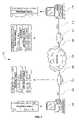
- FIG. 1is a block diagram of an existing system 100 for connecting multiple hosts, such as first host 102 and second host 116 , to one another.
- Each host 102 or 116is typically a desktop computer.
- the hosts 102 and 116are coupled to one another through gateways, such as first gateway 106 and second gateway 112 , coupled to the Internet 110 .
- Gateways 106 or 112are any bi-directional Internet Protocol (IP) communication devices that couple to the Internet 110 via communication links 108 .
- IPInternet Protocol
- Such gatewaysinclude analog “dial-up” modems, DSL gateways, cable modems, or the like.
- the first host 102couples to the first gateway 106 via a first local network, such as a first Local Area Network (LAN) 104 .
- the second host 116couples to the second gateway 112 via a second local network, such as an second Local Area Network (LAN) 114 .
- the first LAN and second LANsare typically Ethernet networks, where Ethernet is well understood in the art to be the most widely used LAN access method, defined by the Institute of Electrical and Electronics Engineers (IEEE) as the 802.3 standard.
- Packets routed from one host to anotherare routed using the Transmission Control Protocol/Internet Protocol (TCP/IP) communications protocol.
- TCP/IPTransmission Control Protocol/Internet Protocol
- the first host 102having an IP address and sub-network (hereinafter “subnet”) mask of 64.1.1.5/30, addresses a packet to the second host 116 having an IP address and subnet mask of 64.1.1.9/30.
- the second host 116is not on the same local network as the first host 102 , the first host consults its routing table to determine where to send the packet.
- the first host's routing tableinforms the first host to send the packet to its Default Gateway (D.G.), which in this case is the IP address and subnet mask of 64.1.1.6/30.
- D.G.Default Gateway
- a Default Gatewayis the router entry used to forward all traffic that is not addressed to a host within the local network. However, a Default Gateway is not to be confused with the gateways 106 and 116 .
- the first host 102then sends the packet to the IP address and sub-network mask of 64.1.1.6/30, which is the IP address and sub-network mask of the first gateway 106 .
- the first gateway 106receives the packet and consults its own routing table to ascertain where next to send the packet.
- the first gateway's routing tableinstructs the first gateway 106 to send the packet to its Default Gateway, which is in this case the Internet 110 .
- the first gatewaythen sends the packet to the Internet 100 .
- the packetis subsequently routed through the Internet 110 to the second gateway 112 .
- the second gateway 112receives the packet and consults its routing table to determine where to send the packet.
- the second gateway's routing tableinstructs the second gateway 112 to send any packets addressed to the network of 64.1.1.9/30 to the second LAN 114 (LN 2 ).
- the second gatewaythen forwards the packet to the second LAN 114 , whereafter the second host 116 receives the packet from the second LAN 114 .
- the process for transmitting packets from the second host 116 to the first host 102is similar to that described above.
- a separate routable IP addressis needed for each host and each gateway, where a routable IP address is any address that can be “seen” and accessed from the outside world, i.e., the Internet.
- a routable IP addressis any address that can be “seen” and accessed from the outside world, i.e., the Internet.
- the IP addresses for each host-gateway combinationmust be on the same local network.
- the IP address and subnet mask of the first hosti.e., 64.1.1.5/30
- the IP address and subnet mask of the first gatewayi.e., 64.1.1.6/30
- this subnet mask of /30includes the four IP addresses of 64.1.1.4, 64.1.1.5, 64.1.1.6, and 64.1.1.7.
- a minimum of two routable IP addresses on the same local networkare needed for each host and gateway combination.
- a minimum of four IP addressesmust be assigned to each local network. This is because subnet masks can only divide into networks having a set group of IP addresses in each sub-network. These groups of IP addresses are dictated by the subnet mask, as indicated below.
- IPInternet Protocol
- An Address Resolution Protocol (ARP) requestis received at a gateway coupled to a first local network from a first host also coupled to the first local network.
- the ARP requestincludes a destination IP address of a second host coupled to a second local network.
- a source IP address of the first host and the destination IP addressare within the same IP address sub-network. For example, a source IP address of 64.1.1.1/24 and a destination IP address of 64.1.1.2/24 are within the same sub-network.
- a local network address of the gatewayis then sent to the first host in reply to the ARP request, based on an entry for the destination IP address in an ARP proxy table stored on the gateway.
- a packetis subsequently acquired from the first host addressed to the second host.
- the packet's headerincludes the source IP address and the destination IP address. Finally the packet is transmitted toward the second host.
- the packetis sent to a Default Gateway of the gateway based on a entry for the destination IP address in a routing table stored on the gateway.
- the Default Gatewayis preferably the Internet.
- the packetis transmitted to a third host coupled to a third local network based on a entry for the destination IP address in a routing table stored on the gateway.
- the gatewayis also coupled to the third local network, and again the source IP address and the destination IP address are within the same IP address sub-network.
- the gatewayfor preserving Internet Protocol (IP) addresses.
- the gatewaycomprises a Central Processing Unit (CPU); communications circuitry coupled to a first local network and the Internet, where the communications circuitry has a unique local network address; at least two ports for communicating with the first local network and the Internet; and a memory.
- the memorycomprises an operating system; a Address Resolution Protocol (ARP) table; a routing table; and communication procedures.
- the ARP tablecontains a list of destination IP addresses and associated instructions for sending the local network address to a first host also coupled to the first local network
- the first hosthas a source IP address.
- the routing tablecontains a list of destination IP addresses and associated instructions for routing packets to one of the ports.
- the communication procedurescomprise instructions for receiving an ARP request from the first host.
- the ARP requestincludes a destination IP address of a second host coupled to a second local network. Also, the source IP address and the destination IP address are within the same IP address sub-network.
- the communication proceduresalso comprise instructions for sending the local network address to the first host in reply to the ARP request, based on an entry for the destination IP address in the ARP proxy table.
- the communication proceduresfurther include instructions for receiving a packet from the first host addressed to the second host. The packet includes the source IP address and the destination IP address. Finally, the communication procedures include instructions for transmitting the packet toward the second host.
- a system for preserving Internet Protocol (IP) addressesis also provided.
- the systemincludes a first host having a source IP address and coupled to a first gateway via a first local network.
- the systemalso includes a second host having a destination IP address and coupled to a second gateway via a second local network.
- the systemincludes the Internet coupled to both the first gateway and the second gateway.
- the gatewayincludes components are described above.
- the computer program productcomprises a computer readable storage and a computer program stored therein.
- the computer programcomprises instructions and procedures as described above.
- routable IP addresses on the same networkcan be assigned to hosts and gateways on separate and distinct local networks, thereby preserving IP addresses and reducing waste. Therefore, a single routable IP address can be given to each host and gateway without having to assign a minimum of four routable IP addresses to each local network.
- FIG. 1is a block diagram of an existing system for connecting multiple hosts to one another;
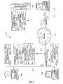
- FIG. 2is a block diagram of a system for preserving routable IP addresses using ARP proxy, according to an embodiment of the invention
- FIG. 3is a block diagram of either of the gateways shown in FIG. 2 ;
- FIG. 4is a flow chart of a method for preserving routable IP addresses using ARP proxy, according to an embodiment of the invention
- FIG. 5is a block diagram of another system for preserving routable IP addresses using ARP proxy, according to another embodiment of the invention.
- FIG. 6is a block diagram of yet another system for preserving routable IP addresses using ARP proxy, according to yet another embodiment of the invention
- any reference numeralgenerally indicates the number of the figure where the reference numeral can be found. For example, 112 can be found in FIG. 1 , and 618 can be found in FIG. 6 .
- FIG. 2is a block diagram of a system 200 for preserving routable IP addresses using ARP proxy, according to an embodiment of the invention.
- the system 200connects multiple hosts, such as a first host 202 and a second host 216 , to one another.
- the hosts 202 or 216may be any type of computing device that is capable of communicating over a network, such as desktop computers, or the like.
- the hosts 202 and 216preferably include standard components, such as at least one data processor or central processing unit (CPU); a memory; communications circuitry, such as a Network Interface Card (NIC); user interface devices, such as a monitor and keyboard; and at least one bus that interconnects these components.
- the communications circuitrypreferably includes a unique local network address, such as a Ethernet address or Media Access Control (MAC) address.
- the memorypreferably includes an operating system, such as MICROSOFT WINDOWSTM or MAC OSTM, having instructions for communicating, processing, accessing, storing, or searching data, etc.
- the memoryalso preferably includes communication procedures; network access procedures, such as MICROSOFT'STM INTERNET EXPLORERTM or NETSCAPE'STM NAVIGATORTM; and an Address Resolution Protocol (ARP) table.
- network access proceduressuch as MICROSOFT'STM INTERNET EXPLORERTM or NETSCAPE'STM NAVIGATORTM
- ARPAddress Resolution Protocol
- the memoryincludes a unique routable IP address and routing table as shown in FIG. 2 .
- the first host 202is coupled to a first gateway 206 via a first local network 204
- the second host 216is coupled to a second gateway 212 via a second local network 214
- the first and second local networks 204 and 214are preferably Local Area Networks (LANs) that communicate using Ethernet.
- LANsLocal Area Networks
- Ethernetis the most widely used LAN access method, and is defined by the Institute of Electrical and Electronics Engineers (IEEE) as the 802.3 standard.
- IEEEInstitute of Electrical and Electronics Engineers
- These first and second local networksmay be wired or wireless networks, such as that defined by the IEEE 802.11b standard.
- the first and second gateways 206 and 212are any bi-directional Internet Protocol (IP) communication devices that couple to the Internet 210 via communication links 208 .
- IPInternet Protocol
- Such Bi-directional IP communication devicesinclude, analog “dial-up” modems, Digital Subscriber Line (DSL) gateways, cable modems, or the like.
- Communication links 208include any type of communication link or network, such as Digital Subscriber Line (DSL) networks, cable networks, Asynchronous Transfer Mode (ATM) networks, wireless networks, or the like.
- TCP/IPTransmission Control Protocol/Internet Protocol
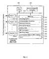
- FIG. 3is a block diagram of either of the gateways 206 or 212 shown in FIG. 2 .
- Gateways 206 or 212preferably include components, such as least one data processor or central processing unit (CPU) 302 ; a memory 312 ; communications circuitry 304 , such as a Network Interface Card (NIC); communications ports 306 ( 1 )-(N) that couple to host 202 or 216 ( FIG. 2 ) and to the Internet 210 ( FIG. 2 ); and at least one bus 310 that interconnects these components.
- the memory 312preferably includes an operating system 314 , such as VXWORKSTM, or IMBEDDED LINUXTM, having instructions for communicating, processing, accessing, storing, or searching data, etc.
- the memory 312also preferably includes communication procedures 316 ; a gateway IP address 318 (also shown in FIGS. 2 , 5 , or 6 ); routing procedures 320 ; a routing table 322 (also shown in FIGS. 2 , 5 , or 6 ); Address Resolution Protocol (ARP) procedures 324 ; an ARP proxy table 326 (also shown in FIGS. 2 , 5 , or 6 ); a local network address (MAC address) 328 ; and a cache 330 for temporarily storing data.
- ARPAddress Resolution Protocol
- the routing procedures 320use the routing table 322 to determine where to send IP packets.
- the routing table 322preferably contains multiple entries, each having a destination IP address (and subnet mask) and an associated port 306 ( 1 )-(N) where to send a packet addressed to the destination IP address, as shown in FIGS. 2 , 5 , or 6 .
- the routing table 322instructs the gateway to send the packet to the local network.
- the routing table 322instructs the gateway to send the packet to the gateway's Default Gateway (D.G.), which is typically the Internet.
- D.G.Default Gateway
- the ARP procedures 324use the ARP proxy table 326 to determine whether or not to publish the gateway's local network address 328 .
- the ARP proxy table 326preferably contains multiple entries, each having a destination IP address (and subnet mask) and an associated instruction whether or not to publish gateway's local network address (MAC address) 328 , as shown in FIGS. 2 , 5 , or 6 .
- MAC addressgateway's local network address
- FIGS. 2 , 5 , or 6For example, if the gateway receives an ARP request having any destination IP address within the ISP's network, then the gateway publishes its own local network address (MAC address) 328 back to the local network address (MAC address) of the host from where the ARP request came. However, if the ARP request has a destination IP address of a host within its local network, then the gateway does not publish its own local network address (MAC address).
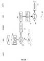
- FIG. 4is a flow chart of a method 400 for preserving routable IP addresses using ARP proxy, according to an embodiment of the invention.
- FIG. 2For ease of explanation of the method 400 , an example of communicating a packet in system 200 ( FIG. 2 ) will now be described. It should, however, be appreciated that the example is used merely to aid in the explanation, and that the method 400 applies equally as well to FIGS. 5 and 6 . Reference numerals used in this example refer to both FIGS. 2 and 4 .
- Each gateway that runs TCP/IPmakes routing decisions. These decisions are controlled by the routing table 322 ( FIG. 3 ) on each gateway.
- the routing tableis built automatically, based on the current TCP/IP configuration of the gateway.
- the gatewayuses the default route if no other host or network route matches the destination address included in an IP packet.
- the default routetypically forwards an IP datagram (for which there is no matching or explicit local route) to a Default Gateway address for a router on the local subnet. Because the router that corresponds to the Default Gateway contains information about the network IDs of the other IP subnets within the larger TCP/IP Internet, it forwards the packet to other routers until the packet is eventually delivered to a gateway that is connected to the specified destination host or subnet within the larger network.
- an ISPsends 436 routing configuration data to the gateways 206 and 212 ( FIG. 2 ). This routing data is used to build a routing table 322 ( FIG. 3 ) on each gateway. For example, the ISP may send routing configuration data to the gateways each time that a customer couples a new host or local network to a gateway. Alternatively, the routing table 322 ( FIG. 3 ) is built 438 automatically, each time a new host or local network is coupled to a gateway. In yet another embodiment, the routing table, including a Default Gateway address, may be entered manually into each gateway.
- the ARP proxy table 326( FIG. 3 ) is automatically generated 440 from the routing table 322 ( FIG. 3 ).
- the ARP proxy tableis setup with distinct sub-tables for each local network coupled to the gateway. For each sub-table or local network, an IP address for each host coupled to that local network is provided. A corresponding instruction not to send the gateway's local network address is provided for each local host IP address. An instruction to send the gateway's local network address is provided for all other IP addresses.
- the first host 202 having an IP address and subnet mask of 64.1.1.1/24wants 402 to transmit a packet to the second host 216 having an IP address and subnet mask of 64.1.1.2/24.
- the first host 202determines 403 whether the destination IP address is on its network. In other words, whether the second IP address (destination IP address) of the second host is on the same sub-network or local network as the first IP address (source IP address) of the first host.
- the first hostdetermines from its routing table to send the packet to the first host's Default Gateway, whereafter the IP packet is transmitted 404 to the first hosts Default Gateway, which in this case is the IP address of the first gateway 206 .
- the first hostbroadcasts 406 an ARP request.
- the first host 202assumes ( 403 -Yes) that the second host 216 is on its own first local network 204 .
- the first host 202 and the second hosthave been assigned IP addresses that appear to be on the same sub-network or local network, i.e., 64.1.1.1/24 and 64.1.1.2/24, where /24 includes 256 unique IP addresses in the same network.
- the first host 202assumes that the second host 216 is on its first local network 204 , it attempts to send the packet to the second host 216 over the first local network 204 .
- Communication over a local networkoccurs using the datalink or Media Access Control (MAC) layer of the International Organization for Standardization's (ISO) Open System Interconnection (OSI) model.
- the datalink or MAC layeris a protocol that controls access to the physical transmission medium on a local network.
- MAC layer functionalityis built into the communications circuitry and includes a unique local network address that identifies each network card attached to the network.
- the common MAC layer standard used in Ethernetis the Carrier Sense Multiple Access/Collision Detection (CSMA/CD) architecture.
- CSMA/CDCarrier Sense Multiple Access/Collision Detection
- a source hostTo communicate within the first local network 204 , a source host must first ascertain the local network address, typically the MAC address, of the destination host.
- ARPis used to obtain the local network address of the destination host from its known IP address, and is extensively used by all hosts in an Ethernet network. Therefore, to ascertain the local network address of the second host 216 from the second host's known IP address, the first host 202 broadcasts 406 an ARP request onto the first local network 204 (LN 1 ).
- the ARP requestincludes a source IP address (64.1.1.1) and source local network address of the first host and a destination IP address (64.1.1.2) of the second host.
- Each device coupled to the first local network 204receives this ARP request. Further details of ARP requests can be found in RFC 826, which is hereby incorporated by reference.
- the host with the specified destination IP addresssends an ARP reply packet to the originating host with its destination local network address.
- the second host 216does not receive the ARP request and, therefore, cannot reply with its local network address.
- the first gateway 206receives 408 the ARP request and looks-up 410 the destination IP address in its own ARP proxy table 326 ( FIG. 3 ).
- the ARP procedures 324determine 412 whether or not to send the first gateway's local network address back to the host that made the ARP request.
- the ARP proxy table on the first gatewayinstructs the first gateway to send its local network address back to the host that made the ARP request. This is the case for all destination IP addresses, except for the destination IP addresses of any hosts coupled directly to the first local network. Stated differently, the ARP proxy table will not instruct the first gateway to send back its local network address if the destination IP address in the ARP request is a host coupled directly to the first local network 204 .
- the first gateway 206will not send its local network address back to the first host 202 . However, if the destination IP address is 64.1.1.0/24, i.e., is any other host on the network except the first host 202 (64.1.1.1/32), then the first gateway 206 will send its local network address back to the first host 202 .
- the first gateway 206sends its local network address back to the host that made the ARP request, i.e., back to the first host 202 . If, however, it is determined from the ARP proxy table that the first gateway's local network address must not be sent ( 412 -No), then the first gateway does not send its local network address back to the host that made the ARP request.
- the first host 202receives 414 the first gateway's local network address, and thereafter transmits 416 the packet back to the local network address of the first gateway 206 .
- the packetincludes a header containing at least a source IP address of the first host 202 , i.e., 64.1.1.1, and a destination IP address of the second host 216 , i.e., 64.1.1.2.
- the first host 202then updates its ARP table so that it will send all future packets addressed to the second host's IP address, to the first gateway's local network address.
- the first gatewayreceives 418 the packet and looks-up 420 the destination IP address in its routing table 322 ( FIG. 3 ) using the routing procedures 320 ( FIG. 3 ). From the routing table and the destination IP address, the routing procedures 320 ( FIG. 3 ) determine which port to send the packet to. In general, as can be seen from the first gateway's routing table in FIG. 2 , the routing table will instruct the first gateway 206 to send all packets with a destination IP address of a host directly coupled to the first local network 204 , to the gateway's first local network 204 .
- the routing tablewill instruct the first gateway 206 to send all packets with a destination IP address of a host not directly coupled to the first local network 204 , to the gateway's Default Gateway, which in this case is the Internet 210 .
- the gateway's Default Gatewaywhich in this case is the Internet 210 .
- all destination IP addresses, except for the destination IP addresses of any hosts coupled to the first local networkwill be sent to the Default Gateway.
- the packetis sent to the Default Gateway, which in this case is the Internet. If it is determined from the routing table not to send the packet to the first gateway's Default Gateway (D.G.) ( 422 -No), then the packet is sent elsewhere as explained in further detail below in relation to FIG. 6 .
- the packetis routed 426 through the Internet to the second gateway 212 .
- the second gateway 212receives 428 the packet and looks-up 430 the destination IP address in its routing table.
- the routing procedures on the second gatewaydetermine which port 306 ( 1 )-(N) ( FIG. 3 ) to send the packet to. This means that with a destination address of 64.1.1.2/32 ( 432 -Yes), the second gateway's routing table instructs the second gateway to send the packet to the second local network 214 (LN 2 ).
- the packetis then received 434 by the second host 216 .
- a packet sent from the second host 216 to the first host 202will follow similar processes to those described above.
- IP addresses on the same networkcan be assigned to hosts and gateways on separate and distinct local networks, thereby preserving IP addresses and reducing waste.
- FIG. 5is a block diagram of another system 500 for preserving routable IP addresses using ARP proxy, according to another embodiment of the invention.
- a first host 502 and a third host 504are both coupled to the same first local network 506 (LN 1 ) which is coupled to a first gateway 508 .
- the first gateway 508is coupled to the Internet 510 .
- a second host 516is coupled to a second gateway 512 via a second local network 514 (LN 2 ).
- the second gateway 512is also coupled to the Internet 510 .
- the packetis communicated as described above in relation to FIG. 4 .
- the first host 502 having an IP address (and subnet mask) of 64.1.1.1/24wants to send a packet to the second host having an IP address (and subnet mask) of 64.1.1.3/24.
- the first host 502assumes that the second host 516 is on the first local network 506 (LN 1 ). Therefore, the first host broadcasts an ARP request containing its local network address, its source IP address, and the destination IP address of the second host 516 .
- the first gateway 508receives the ARP request and looks-up the destination IP address in its ARP proxy table.
- the first gateway's ARP proxy tableinstructs the first gateway 508 to send the first gateway's local network address to the first host.
- the ARP proxy tablewill instruct the gateway to send its local network address for all destination IP addresses except for the destination IP addresses of any hosts coupled directly to the first local network 506 , i.e., except for the first and third hosts 502 and 504 , respectively.
- the first host 502receives the local network address of the first gateway, and sends the packet to that local network address.
- the packet's headerincludes the destination IP address of the second host 516 , ie., 64.1.1.3/24.
- the gatewayreceives the packet, and looks-up the destination IP address in its routing table.
- the routing tableinstructs the first gateway to send the packet to its Default Gateway, i.e., the Internet 510 .
- the packetis routed through the Internet to the second gateway.
- the second gatewayreceives the packet and looks-up the destination IP address in its routing table.
- the destination IP addressi.e., 64.1.1.3/32, is the IP address of a host directly coupled to the second local network 514 , therefore, the routing table instructs the second gateway 512 to send the packet to the second local network 514 (LN 2 ).
- the packetis shortly thereafter received by the second host. Packets sent from the third host to the second host, or from the second host to either of the first or third hosts, are sent in a similar manner.
- packets sent from the first host to the third hostare sent using the standard ARP mechanisms.
- the third host 504assumes that the first host is on its same local network 506 . In this case, this assumption is correct, as the first host is on its same local network 506 .
- the third host 504broadcasts an ARP request onto the first local network 506 .
- the ARP requestis received by both the first host 502 and the first gateway 508 .
- the first gatewaylooks up the destination IP address, i.e., 64.1.1.1/24, in its ARP proxy table and ascertains that it must not send out its local network address. This is the case whenever the destination IP address is an IP address of any host on the first local network 506 .
- the first host 502also receives the ARP request and looks up in its ARP table whether or not to respond by sending its own local network address. As the destination IP address is the IP address of the first host 502 , it responds by sending its own local network address (MAC address) back to the third host 504 . The first and third hosts then update their ARP tables for future communication between one another. The third host 504 then sends the packet to the first host's local network address, whereafter the first host receives the packet. The first host 502 sends packets to the third host 504 in a similar manner.
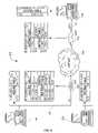
- FIG. 6is a block diagram of yet another system 600 for preserving routable IP addresses using ARP proxy, according to yet another embodiment of the invention.
- a first host 602is coupled to a first gateway 610 via a first local network 604 (LN 1 ).
- a third host 606is coupled to the first gateway 610 via a third local network 608 (LN 3 ).
- Each of the first and third local networkspreferably attach to one of the first gateway's ports 306 ( 1 )-(N) ( FIG. 3 ).
- the first gateway 610is coupled to the Internet 612 .
- a second host 618is coupled to a second gateway 614 via a second local network 616 (LN 2 ).
- the second gateway 614is also coupled to the Internet 612 .
- Communication between the first host 602 or the third host 606 , and the second host 618occurs in a similar manner to that described above in relation to FIGS. 2 , 4 , and 5 .
- the first host 602 and the third host 606are on different local networks, communication between the first and third hosts is more complex than that described above in relation to FIG. 5 .
- the first host 602 having an IP address (and subnet mask) of 65.1.1.2/24wants to send a packet to the third host having an IP address (and subnet mask) of 65.1.1.1/24. Because of their IP addresses and subnet masks, the first host 602 assumes that the third host 606 is on the first local network 604 (LN 1 ). Therefore, the first host broadcasts 406 ( FIG.
- the third host 604receives the ARP request and looks-up the destination IP address in its ARP proxy table.
- the ARP proxy tableincludes a sub-table for each local network connected to it, i.e., first local network 604 (LN 1 ) and third local network 608 (LN 3 ). Therefore, the ARP procedures 324 ( FIG. 3 ) on the first gateway look-up 410 ( FIG. 4 ) the destination IP address for the local network from where the ARP request came, i.e., the third local network. Looking-up the destination IP address of 65.1.1.1/25 reveals that the first gateway 610 must send ( 412 -Yes) ( FIG. 4 ) its local network address to the first host 602 . The first host 602 receives 414 ( FIG. 4 ) the local network address of the first gateway 610 and transmits 416 ( FIG. 4 ) the packet to the first gateway's local network address.
- the first gateway 610receives 418 ( FIG. 4 ) the packet and looks-up 420 ( FIG. 4 ) where to send the packet in its routing table.
- the packet's headercontains the source IP address of the first host 602 , the destination IP address of the third host, and the local network address of the first gateway.
- the routing tableinstructs the first gateway 610 to send the packet to the third local network 608 (LN 3 ), whereafter the gateway sends ( 424 -Yes) ( FIG. 4 ) the packet to the third local network 608 (LN 3 ).
- the third host 606then receives the packet from the third local network 608 . Packets sent from the third host to the first host occur in a similar manner.
- routable IP addresses on the same networkcan be assigned to hosts and gateways on separate and distinct local networks, thereby preserving IP addresses and reducing waste. Therefore, a single routable IP address can be given to each host and gateway without having to assign a minimum of four routable IP addresses to each local network.
- the ARP proxy table and routing table on each gatewayis remotely updated by an ISP (not shown) whenever a new host is added to the local network that is coupled to the gateway.
Landscapes
- Engineering & Computer Science (AREA)
- Computer Networks & Wireless Communication (AREA)
- Signal Processing (AREA)
- Data Exchanges In Wide-Area Networks (AREA)
Abstract
Description
| SUBNET MASK | SHORTHAND | NUMBER OF ADDRESSES |
| 255.255.255.0 | /24 [8-bit] | 28= | 256 | = 254 hosts + 1 bcast + 1 net base |
| 255.255.255.128 | /25 [7-bit] | 27= | 128 | = 126 hosts + 1 bcast + 1 net base |
| 255.255.255.192 | /26 [6-bit] | 26= | 64 | = 62 hosts + 1 bcast + 1 net base |
| 255.255.255.224 | /27 [5-bit] | 25= | 32 | = 30 hosts + 1 bcast + 1 net base |
| 255.255.255.240 | /28 [4-bit] | 24= | 16 | = 14 hosts + 1 bcast + 1 net base |
| 255.255.255.248 | /29 [3-bit] | 23= | 8 | = 6 hosts + 1 bcast + 1 net base |
| 255.255.255.252 | /30 [2-bit] | 22= | 4 | = 2 hosts + 1 bcast + 1 net base |
| 255.255.255.254 | /31 [1-bit] | 21= | — | invalid (no possible hosts) |
| 255.255.255.255 | /32 [0-bit] | 20= | 1 | a host route |
Claims (21)
Priority Applications (1)
| Application Number | Priority Date | Filing Date | Title |
|---|---|---|---|
| US10/295,431US7512136B2 (en) | 2002-11-15 | 2002-11-15 | Apparatus and method for preserving routable IP addresses using ARP proxy |
Applications Claiming Priority (1)
| Application Number | Priority Date | Filing Date | Title |
|---|---|---|---|
| US10/295,431US7512136B2 (en) | 2002-11-15 | 2002-11-15 | Apparatus and method for preserving routable IP addresses using ARP proxy |
Publications (2)
| Publication Number | Publication Date |
|---|---|
| US20040095943A1 US20040095943A1 (en) | 2004-05-20 |
| US7512136B2true US7512136B2 (en) | 2009-03-31 |
Family
ID=32297196
Family Applications (1)
| Application Number | Title | Priority Date | Filing Date |
|---|---|---|---|
| US10/295,431Expired - LifetimeUS7512136B2 (en) | 2002-11-15 | 2002-11-15 | Apparatus and method for preserving routable IP addresses using ARP proxy |
Country Status (1)
| Country | Link |
|---|---|
| US (1) | US7512136B2 (en) |
Cited By (11)
| Publication number | Priority date | Publication date | Assignee | Title |
|---|---|---|---|---|
| US20060018325A1 (en)* | 2004-07-06 | 2006-01-26 | Conrad Jeffrey R | Method and system for generating ranges of internet protocol addresses |
| US20060224774A1 (en)* | 2005-04-05 | 2006-10-05 | Masamichi Tanji | Communication apparatus and communication control method |
| US20110004661A1 (en)* | 2009-07-01 | 2011-01-06 | Fujitsu Network Communications, Inc. | Methods and systems for managing network elements |
| US8027339B2 (en) | 1997-03-12 | 2011-09-27 | Nomadix, Inc. | System and method for establishing network connection |
| US8156246B2 (en) | 1998-12-08 | 2012-04-10 | Nomadix, Inc. | Systems and methods for providing content and services on a network system |
| US8190708B1 (en) | 1999-10-22 | 2012-05-29 | Nomadix, Inc. | Gateway device having an XML interface and associated method |
| US8266269B2 (en) | 1998-12-08 | 2012-09-11 | Nomadix, Inc. | Systems and methods for providing content and services on a network system |
| US8613053B2 (en) | 1998-12-08 | 2013-12-17 | Nomadix, Inc. | System and method for authorizing a portable communication device |
| US20140064148A1 (en)* | 2012-09-04 | 2014-03-06 | Cisco Technology, Inc. | Distributed Proxy Addressing Operations |
| US10412439B2 (en) | 2002-09-24 | 2019-09-10 | Thomson Licensing | PVR channel and PVR IPG information |
| US20240154936A1 (en)* | 2022-11-09 | 2024-05-09 | Charter Communications Operating, Llc | Proxy address resolution protocol for distributed local area network communications |
Families Citing this family (100)
| Publication number | Priority date | Publication date | Assignee | Title |
|---|---|---|---|---|
| US6658091B1 (en) | 2002-02-01 | 2003-12-02 | @Security Broadband Corp. | LIfestyle multimedia security system |
| US7114004B2 (en)* | 2003-05-08 | 2006-09-26 | Vernall, Inc. | Premium messaging exchange |
| KR100568178B1 (en)* | 2003-07-18 | 2006-04-05 | 삼성전자주식회사 | Gateway device and control method |
| US10237237B2 (en) | 2007-06-12 | 2019-03-19 | Icontrol Networks, Inc. | Communication protocols in integrated systems |
| US10200504B2 (en) | 2007-06-12 | 2019-02-05 | Icontrol Networks, Inc. | Communication protocols over internet protocol (IP) networks |
| US11244545B2 (en) | 2004-03-16 | 2022-02-08 | Icontrol Networks, Inc. | Cross-client sensor user interface in an integrated security network |
| US11677577B2 (en) | 2004-03-16 | 2023-06-13 | Icontrol Networks, Inc. | Premises system management using status signal |
| JP2007529826A (en) | 2004-03-16 | 2007-10-25 | アイコントロール ネットワークス, インコーポレイテッド | Object management network |
| US11489812B2 (en) | 2004-03-16 | 2022-11-01 | Icontrol Networks, Inc. | Forming a security network including integrated security system components and network devices |
| US7711796B2 (en) | 2006-06-12 | 2010-05-04 | Icontrol Networks, Inc. | Gateway registry methods and systems |
| US10348575B2 (en) | 2013-06-27 | 2019-07-09 | Icontrol Networks, Inc. | Control system user interface |
| US10142392B2 (en) | 2007-01-24 | 2018-11-27 | Icontrol Networks, Inc. | Methods and systems for improved system performance |
| US11368429B2 (en) | 2004-03-16 | 2022-06-21 | Icontrol Networks, Inc. | Premises management configuration and control |
| US9729342B2 (en) | 2010-12-20 | 2017-08-08 | Icontrol Networks, Inc. | Defining and implementing sensor triggered response rules |
| US10522026B2 (en) | 2008-08-11 | 2019-12-31 | Icontrol Networks, Inc. | Automation system user interface with three-dimensional display |
| US20090077623A1 (en) | 2005-03-16 | 2009-03-19 | Marc Baum | Security Network Integrating Security System and Network Devices |
| US10339791B2 (en) | 2007-06-12 | 2019-07-02 | Icontrol Networks, Inc. | Security network integrated with premise security system |
| US11343380B2 (en) | 2004-03-16 | 2022-05-24 | Icontrol Networks, Inc. | Premises system automation |
| US11159484B2 (en) | 2004-03-16 | 2021-10-26 | Icontrol Networks, Inc. | Forming a security network including integrated security system components and network devices |
| US8635350B2 (en)* | 2006-06-12 | 2014-01-21 | Icontrol Networks, Inc. | IP device discovery systems and methods |
| US12063220B2 (en) | 2004-03-16 | 2024-08-13 | Icontrol Networks, Inc. | Communication protocols in integrated systems |
| US9141276B2 (en) | 2005-03-16 | 2015-09-22 | Icontrol Networks, Inc. | Integrated interface for mobile device |
| US11113950B2 (en) | 2005-03-16 | 2021-09-07 | Icontrol Networks, Inc. | Gateway integrated with premises security system |
| US10156959B2 (en) | 2005-03-16 | 2018-12-18 | Icontrol Networks, Inc. | Cross-client sensor user interface in an integrated security network |
| US10062273B2 (en) | 2010-09-28 | 2018-08-28 | Icontrol Networks, Inc. | Integrated security system with parallel processing architecture |
| US11316958B2 (en) | 2008-08-11 | 2022-04-26 | Icontrol Networks, Inc. | Virtual device systems and methods |
| US9531593B2 (en) | 2007-06-12 | 2016-12-27 | Icontrol Networks, Inc. | Takeover processes in security network integrated with premise security system |
| US8963713B2 (en) | 2005-03-16 | 2015-02-24 | Icontrol Networks, Inc. | Integrated security network with security alarm signaling system |
| US11201755B2 (en) | 2004-03-16 | 2021-12-14 | Icontrol Networks, Inc. | Premises system management using status signal |
| US10721087B2 (en) | 2005-03-16 | 2020-07-21 | Icontrol Networks, Inc. | Method for networked touchscreen with integrated interfaces |
| US11916870B2 (en) | 2004-03-16 | 2024-02-27 | Icontrol Networks, Inc. | Gateway registry methods and systems |
| US11811845B2 (en) | 2004-03-16 | 2023-11-07 | Icontrol Networks, Inc. | Communication protocols over internet protocol (IP) networks |
| US11277465B2 (en) | 2004-03-16 | 2022-03-15 | Icontrol Networks, Inc. | Generating risk profile using data of home monitoring and security system |
| US11582065B2 (en) | 2007-06-12 | 2023-02-14 | Icontrol Networks, Inc. | Systems and methods for device communication |
| US10380871B2 (en) | 2005-03-16 | 2019-08-13 | Icontrol Networks, Inc. | Control system user interface |
| US20170118037A1 (en) | 2008-08-11 | 2017-04-27 | Icontrol Networks, Inc. | Integrated cloud system for premises automation |
| US7567573B2 (en)* | 2004-09-07 | 2009-07-28 | F5 Networks, Inc. | Method for automatic traffic interception |
| EP1638294A1 (en)* | 2004-09-18 | 2006-03-22 | Zyxel Communications Corporation | Network-connecting method dispensing with IP configuration |
| US11700142B2 (en) | 2005-03-16 | 2023-07-11 | Icontrol Networks, Inc. | Security network integrating security system and network devices |
| US20110128378A1 (en) | 2005-03-16 | 2011-06-02 | Reza Raji | Modular Electronic Display Platform |
| US10999254B2 (en) | 2005-03-16 | 2021-05-04 | Icontrol Networks, Inc. | System for data routing in networks |
| US11615697B2 (en) | 2005-03-16 | 2023-03-28 | Icontrol Networks, Inc. | Premise management systems and methods |
| US20170180198A1 (en) | 2008-08-11 | 2017-06-22 | Marc Baum | Forming a security network including integrated security system components |
| US9306809B2 (en) | 2007-06-12 | 2016-04-05 | Icontrol Networks, Inc. | Security system with networked touchscreen |
| US20120324566A1 (en) | 2005-03-16 | 2012-12-20 | Marc Baum | Takeover Processes In Security Network Integrated With Premise Security System |
| US11496568B2 (en) | 2005-03-16 | 2022-11-08 | Icontrol Networks, Inc. | Security system with networked touchscreen |
| EP1764970A1 (en) | 2005-09-19 | 2007-03-21 | Matsushita Electric Industrial Co., Ltd. | Multiple interface mobile node with simultaneous home- and foreign network connection |
| US20070248085A1 (en)* | 2005-11-12 | 2007-10-25 | Cranite Systems | Method and apparatus for managing hardware address resolution |
| CN100454901C (en)* | 2006-02-17 | 2009-01-21 | 华为技术有限公司 | A method for processing ARP packets |
| US12063221B2 (en) | 2006-06-12 | 2024-08-13 | Icontrol Networks, Inc. | Activation of gateway device |
| US10079839B1 (en) | 2007-06-12 | 2018-09-18 | Icontrol Networks, Inc. | Activation of gateway device |
| EP2068498B1 (en) | 2006-09-25 | 2017-12-13 | Hewlett-Packard Enterprise Development LP | Method and network device for communicating between different components |
| US7822027B2 (en)* | 2006-10-05 | 2010-10-26 | Cisco Technology, Inc. | Network routing to the socket |
| US11706279B2 (en) | 2007-01-24 | 2023-07-18 | Icontrol Networks, Inc. | Methods and systems for data communication |
| US7633385B2 (en) | 2007-02-28 | 2009-12-15 | Ucontrol, Inc. | Method and system for communicating with and controlling an alarm system from a remote server |
| US8451986B2 (en) | 2007-04-23 | 2013-05-28 | Icontrol Networks, Inc. | Method and system for automatically providing alternate network access for telecommunications |
| US10666523B2 (en) | 2007-06-12 | 2020-05-26 | Icontrol Networks, Inc. | Communication protocols in integrated systems |
| US11646907B2 (en) | 2007-06-12 | 2023-05-09 | Icontrol Networks, Inc. | Communication protocols in integrated systems |
| US10523689B2 (en) | 2007-06-12 | 2019-12-31 | Icontrol Networks, Inc. | Communication protocols over internet protocol (IP) networks |
| US11089122B2 (en) | 2007-06-12 | 2021-08-10 | Icontrol Networks, Inc. | Controlling data routing among networks |
| US11212192B2 (en) | 2007-06-12 | 2021-12-28 | Icontrol Networks, Inc. | Communication protocols in integrated systems |
| US11601810B2 (en) | 2007-06-12 | 2023-03-07 | Icontrol Networks, Inc. | Communication protocols in integrated systems |
| US11218878B2 (en) | 2007-06-12 | 2022-01-04 | Icontrol Networks, Inc. | Communication protocols in integrated systems |
| US11423756B2 (en) | 2007-06-12 | 2022-08-23 | Icontrol Networks, Inc. | Communication protocols in integrated systems |
| US12003387B2 (en) | 2012-06-27 | 2024-06-04 | Comcast Cable Communications, Llc | Control system user interface |
| US11316753B2 (en) | 2007-06-12 | 2022-04-26 | Icontrol Networks, Inc. | Communication protocols in integrated systems |
| US10616075B2 (en) | 2007-06-12 | 2020-04-07 | Icontrol Networks, Inc. | Communication protocols in integrated systems |
| US10498830B2 (en) | 2007-06-12 | 2019-12-03 | Icontrol Networks, Inc. | Wi-Fi-to-serial encapsulation in systems |
| US12283172B2 (en) | 2007-06-12 | 2025-04-22 | Icontrol Networks, Inc. | Communication protocols in integrated systems |
| US12184443B2 (en) | 2007-06-12 | 2024-12-31 | Icontrol Networks, Inc. | Controlling data routing among networks |
| US11237714B2 (en) | 2007-06-12 | 2022-02-01 | Control Networks, Inc. | Control system user interface |
| US11831462B2 (en) | 2007-08-24 | 2023-11-28 | Icontrol Networks, Inc. | Controlling data routing in premises management systems |
| US11916928B2 (en) | 2008-01-24 | 2024-02-27 | Icontrol Networks, Inc. | Communication protocols over internet protocol (IP) networks |
| US20090285138A1 (en)* | 2008-05-13 | 2009-11-19 | Tzero Technologies, Inc. | Maintaining wireless communication between Consumer Electronic Control devices |
| US20170185278A1 (en) | 2008-08-11 | 2017-06-29 | Icontrol Networks, Inc. | Automation system user interface |
| US8331369B2 (en)* | 2008-07-10 | 2012-12-11 | At&T Intellectual Property I, L.P. | Methods and apparatus to distribute network IP traffic |
| US11792036B2 (en) | 2008-08-11 | 2023-10-17 | Icontrol Networks, Inc. | Mobile premises automation platform |
| US11758026B2 (en) | 2008-08-11 | 2023-09-12 | Icontrol Networks, Inc. | Virtual device systems and methods |
| US10530839B2 (en) | 2008-08-11 | 2020-01-07 | Icontrol Networks, Inc. | Integrated cloud system with lightweight gateway for premises automation |
| US11729255B2 (en) | 2008-08-11 | 2023-08-15 | Icontrol Networks, Inc. | Integrated cloud system with lightweight gateway for premises automation |
| US11258625B2 (en) | 2008-08-11 | 2022-02-22 | Icontrol Networks, Inc. | Mobile premises automation platform |
| US8638211B2 (en) | 2009-04-30 | 2014-01-28 | Icontrol Networks, Inc. | Configurable controller and interface for home SMA, phone and multimedia |
| US9491085B2 (en) | 2010-05-24 | 2016-11-08 | At&T Intellectual Property I, L.P. | Methods and apparatus to route control packets based on address partitioning |
| US8699484B2 (en) | 2010-05-24 | 2014-04-15 | At&T Intellectual Property I, L.P. | Methods and apparatus to route packets in a network |
| US8836467B1 (en) | 2010-09-28 | 2014-09-16 | Icontrol Networks, Inc. | Method, system and apparatus for automated reporting of account and sensor zone information to a central station |
| US11750414B2 (en) | 2010-12-16 | 2023-09-05 | Icontrol Networks, Inc. | Bidirectional security sensor communication for a premises security system |
| US9147337B2 (en) | 2010-12-17 | 2015-09-29 | Icontrol Networks, Inc. | Method and system for logging security event data |
| US9853891B2 (en)* | 2012-03-02 | 2017-12-26 | Cisco Technology, Inc. | System and method for facilitating communication |
| CN102739545B (en)* | 2012-06-29 | 2015-06-10 | 杭州华三通信技术有限公司 | Method and device for distributing ARP (Address Resolve Protocol) host route |
| US9537793B2 (en)* | 2012-10-10 | 2017-01-03 | Cisco Technology, Inc. | Ensuring any-to-any reachability with opportunistic layer 3 forwarding in massive scale data center environments |
| CN105264869B (en)* | 2013-06-26 | 2019-05-03 | 华为技术有限公司 | A system and method for IP address allocation |
| US9258209B2 (en)* | 2013-07-02 | 2016-02-09 | Dell Products L.P. | System and method for layer 3 proxy routing |
| US11405463B2 (en) | 2014-03-03 | 2022-08-02 | Icontrol Networks, Inc. | Media content management |
| US11146637B2 (en) | 2014-03-03 | 2021-10-12 | Icontrol Networks, Inc. | Media content management |
| US20150256445A1 (en)* | 2014-03-04 | 2015-09-10 | Cisco Technology, Inc. | Avoiding gratuitous address resolution protocol and unsolicited neighborhood discovery during host mobility events |
| US9716687B2 (en)* | 2014-06-19 | 2017-07-25 | Cisco Technology, Inc. | Distributed gateways for overlay networks |
| US9445256B1 (en)* | 2014-10-22 | 2016-09-13 | Sprint Spectrum L.P. | Binding update forwarding between packet gateways |
| US9936430B1 (en) | 2016-03-07 | 2018-04-03 | Sprint Spectrum L.P. | Packet gateway reassignment |
| CN114401243B (en)* | 2022-03-23 | 2022-06-28 | 北京指掌易科技有限公司 | Data packet sending method, device, equipment and medium |
| US12009986B2 (en)* | 2022-04-01 | 2024-06-11 | Forescout Technologies, Inc. | Proactive inspection technique for improved classification |
Citations (16)
| Publication number | Priority date | Publication date | Assignee | Title |
|---|---|---|---|---|
| US6047325A (en)* | 1997-10-24 | 2000-04-04 | Jain; Lalit | Network device for supporting construction of virtual local area networks on arbitrary local and wide area computer networks |
| US6189042B1 (en)* | 1997-04-09 | 2001-02-13 | Alcatel | LAN internet connection having effective mechanism to classify LAN traffic and resolve address resolution protocol requests |
| US20020021689A1 (en)* | 1999-12-30 | 2002-02-21 | Robbins Barry R. | Method and apparatus for transparent internet mobility management |
| US20020052972A1 (en)* | 2000-08-29 | 2002-05-02 | Lg Electronics, Inc. | Communication method among a plurality of virtual LANs in an IP subnet |
| US20020154644A1 (en)* | 2001-04-20 | 2002-10-24 | Werner Lindemann | Method and router for switching data between a local area network and an external appliance |
| US20030028668A1 (en)* | 1998-12-23 | 2003-02-06 | Nokia Wireless Routers Inc. | Unified routing scheme for ad-hoc internetworking |
| US20030037163A1 (en)* | 2001-08-15 | 2003-02-20 | Atsushi Kitada | Method and system for enabling layer 2 transmission of IP data frame between user terminal and service provider |
| US20030088700A1 (en)* | 2001-11-02 | 2003-05-08 | Microsoft Corporation | Method and system for facilitating communication between nodes on different segments of a network |
| US6603769B1 (en)* | 1998-05-28 | 2003-08-05 | Cisco Technology, Inc. | Method and system for improving traffic operation in an internet environment |
| US6701361B1 (en)* | 1996-08-22 | 2004-03-02 | Intermec Ip Corp. | Enhanced mobility and address resolution in a wireless premises based network |
| US20040054799A1 (en)* | 1996-08-22 | 2004-03-18 | Meier Robert C. | Enhanced mobility and address resolution in a wireless premises based network |
| US20040213234A1 (en)* | 2002-05-09 | 2004-10-28 | Koch Christopher D. | Network address assignment in a passive optical network |
| US6822955B1 (en)* | 1998-01-22 | 2004-11-23 | Nortel Networks Limited | Proxy server for TCP/IP network address portability |
| US6870840B1 (en)* | 2000-08-16 | 2005-03-22 | Alcatel | Distributed source learning for data communication switch |
| US7088739B2 (en)* | 2001-11-09 | 2006-08-08 | Ericsson Inc. | Method and apparatus for creating a packet using a digital signal processor |
| US7185106B1 (en)* | 2002-11-15 | 2007-02-27 | Juniper Networks, Inc. | Providing services for multiple virtual private networks |
- 2002
- 2002-11-15USUS10/295,431patent/US7512136B2/ennot_activeExpired - Lifetime
Patent Citations (22)
| Publication number | Priority date | Publication date | Assignee | Title |
|---|---|---|---|---|
| US20050025129A1 (en)* | 1996-08-22 | 2005-02-03 | Meier Robert C. | Enhanced mobility and address resolution in a wireless premises based network |
| US20040054799A1 (en)* | 1996-08-22 | 2004-03-18 | Meier Robert C. | Enhanced mobility and address resolution in a wireless premises based network |
| US6701361B1 (en)* | 1996-08-22 | 2004-03-02 | Intermec Ip Corp. | Enhanced mobility and address resolution in a wireless premises based network |
| US6189042B1 (en)* | 1997-04-09 | 2001-02-13 | Alcatel | LAN internet connection having effective mechanism to classify LAN traffic and resolve address resolution protocol requests |
| US6047325A (en)* | 1997-10-24 | 2000-04-04 | Jain; Lalit | Network device for supporting construction of virtual local area networks on arbitrary local and wide area computer networks |
| US6822955B1 (en)* | 1998-01-22 | 2004-11-23 | Nortel Networks Limited | Proxy server for TCP/IP network address portability |
| US6603769B1 (en)* | 1998-05-28 | 2003-08-05 | Cisco Technology, Inc. | Method and system for improving traffic operation in an internet environment |
| US7159035B2 (en)* | 1998-12-23 | 2007-01-02 | Nokia Corporation | Unified routing scheme for ad-hoc internetworking |
| US20030028668A1 (en)* | 1998-12-23 | 2003-02-06 | Nokia Wireless Routers Inc. | Unified routing scheme for ad-hoc internetworking |
| US20030037167A1 (en)* | 1998-12-23 | 2003-02-20 | Nokia Wireless Routers Inc. | Unified routing scheme for ad-hoc internetworking |
| US20020021689A1 (en)* | 1999-12-30 | 2002-02-21 | Robbins Barry R. | Method and apparatus for transparent internet mobility management |
| US6870840B1 (en)* | 2000-08-16 | 2005-03-22 | Alcatel | Distributed source learning for data communication switch |
| US20020052972A1 (en)* | 2000-08-29 | 2002-05-02 | Lg Electronics, Inc. | Communication method among a plurality of virtual LANs in an IP subnet |
| US20020154644A1 (en)* | 2001-04-20 | 2002-10-24 | Werner Lindemann | Method and router for switching data between a local area network and an external appliance |
| US20030037163A1 (en)* | 2001-08-15 | 2003-02-20 | Atsushi Kitada | Method and system for enabling layer 2 transmission of IP data frame between user terminal and service provider |
| US20030088700A1 (en)* | 2001-11-02 | 2003-05-08 | Microsoft Corporation | Method and system for facilitating communication between nodes on different segments of a network |
| US6895443B2 (en)* | 2001-11-02 | 2005-05-17 | Microsoft Corporation | Method and system for facilitating communication between nodes on different segments of a network |
| US7088739B2 (en)* | 2001-11-09 | 2006-08-08 | Ericsson Inc. | Method and apparatus for creating a packet using a digital signal processor |
| US20040213234A1 (en)* | 2002-05-09 | 2004-10-28 | Koch Christopher D. | Network address assignment in a passive optical network |
| US20050018681A1 (en)* | 2002-05-09 | 2005-01-27 | Optical Solutions, Inc. | Network address assignment in a passive optical network |
| US7020157B2 (en)* | 2002-05-09 | 2006-03-28 | Optical Solutions, Inc. | Network address assignment in a passive optical network |
| US7185106B1 (en)* | 2002-11-15 | 2007-02-27 | Juniper Networks, Inc. | Providing services for multiple virtual private networks |
Cited By (32)
| Publication number | Priority date | Publication date | Assignee | Title |
|---|---|---|---|---|
| US8027339B2 (en) | 1997-03-12 | 2011-09-27 | Nomadix, Inc. | System and method for establishing network connection |
| US8594107B2 (en) | 1997-03-12 | 2013-11-26 | Nomadix, Inc. | System and method for establishing network connection |
| US8364806B2 (en) | 1998-12-08 | 2013-01-29 | Nomadix, Inc. | Systems and methods for providing content and services on a network system |
| US8370477B2 (en) | 1998-12-08 | 2013-02-05 | Nomadix, Inc. | Systems and methods for providing content and services on a network system |
| US10110436B2 (en) | 1998-12-08 | 2018-10-23 | Nomadix, Inc. | Systems and methods for providing content and services on a network system |
| US8156246B2 (en) | 1998-12-08 | 2012-04-10 | Nomadix, Inc. | Systems and methods for providing content and services on a network system |
| US8788690B2 (en) | 1998-12-08 | 2014-07-22 | Nomadix, Inc. | Systems and methods for providing content and services on a network system |
| US8244886B2 (en) | 1998-12-08 | 2012-08-14 | Nomadix, Inc. | Systems and methods for providing content and services on a network system |
| US8266266B2 (en) | 1998-12-08 | 2012-09-11 | Nomadix, Inc. | Systems and methods for providing dynamic network authorization, authentication and accounting |
| US8266269B2 (en) | 1998-12-08 | 2012-09-11 | Nomadix, Inc. | Systems and methods for providing content and services on a network system |
| US9160672B2 (en) | 1998-12-08 | 2015-10-13 | Nomadix, Inc. | Systems and methods for controlling user perceived connection speed |
| US10341243B2 (en) | 1998-12-08 | 2019-07-02 | Nomadix, Inc. | Systems and methods for providing content and services on a network system |
| US8725888B2 (en) | 1998-12-08 | 2014-05-13 | Nomadix, Inc. | Systems and methods for providing content and services on a network system |
| US8725899B2 (en) | 1998-12-08 | 2014-05-13 | Nomadix, Inc. | Systems and methods for providing content and services on a network system |
| US8606917B2 (en) | 1998-12-08 | 2013-12-10 | Nomadix, Inc. | Systems and methods for providing content and services on a network system |
| US8613053B2 (en) | 1998-12-08 | 2013-12-17 | Nomadix, Inc. | System and method for authorizing a portable communication device |
| US9548935B2 (en) | 1998-12-08 | 2017-01-17 | Nomadix, Inc. | Systems and methods for providing content and services on a network system |
| US8713641B1 (en) | 1998-12-08 | 2014-04-29 | Nomadix, Inc. | Systems and methods for authorizing, authenticating and accounting users having transparent computer access to a network using a gateway device |
| US8516083B2 (en) | 1999-10-22 | 2013-08-20 | Nomadix, Inc. | Systems and methods of communicating using XML |
| US8190708B1 (en) | 1999-10-22 | 2012-05-29 | Nomadix, Inc. | Gateway device having an XML interface and associated method |
| US10412439B2 (en) | 2002-09-24 | 2019-09-10 | Thomson Licensing | PVR channel and PVR IPG information |
| US9185074B2 (en)* | 2004-07-06 | 2015-11-10 | Hewlett-Packard Development Company, L.P. | Method and system for generating ranges of internet protocol addresses |
| US20060018325A1 (en)* | 2004-07-06 | 2006-01-26 | Conrad Jeffrey R | Method and system for generating ranges of internet protocol addresses |
| US8832312B2 (en)* | 2005-04-05 | 2014-09-09 | Canon Kabushiki Kaisha | Communication apparatus and communication control method |
| US20060224774A1 (en)* | 2005-04-05 | 2006-10-05 | Masamichi Tanji | Communication apparatus and communication control method |
| US8046445B2 (en) | 2009-07-01 | 2011-10-25 | Fujitsu Limited | Methods and systems for managing network elements |
| US20110004661A1 (en)* | 2009-07-01 | 2011-01-06 | Fujitsu Network Communications, Inc. | Methods and systems for managing network elements |
| US9042272B2 (en)* | 2012-09-04 | 2015-05-26 | Cisco Technology, Inc. | Distributed proxy addressing operations |
| US9450914B2 (en) | 2012-09-04 | 2016-09-20 | Cisco Technology, Inc. | Distributed proxy addressing operations |
| US20140064148A1 (en)* | 2012-09-04 | 2014-03-06 | Cisco Technology, Inc. | Distributed Proxy Addressing Operations |
| US20240154936A1 (en)* | 2022-11-09 | 2024-05-09 | Charter Communications Operating, Llc | Proxy address resolution protocol for distributed local area network communications |
| US12341749B2 (en)* | 2022-11-09 | 2025-06-24 | Charter Communications Operating, Llc | Proxy address resolution protocol for distributed local area network communications |
Also Published As
| Publication number | Publication date |
|---|---|
| US20040095943A1 (en) | 2004-05-20 |
Similar Documents
| Publication | Publication Date | Title |
|---|---|---|
| US7512136B2 (en) | Apparatus and method for preserving routable IP addresses using ARP proxy | |
| US6480508B1 (en) | Router-based domain name system proxy agent using address translation | |
| EP0943201B1 (en) | Method for using dhcp to override learned ip addresses in a network | |
| US7046666B1 (en) | Method and apparatus for communicating between divergent networks using media access control communications | |
| US20020165972A1 (en) | Methods and apparatus for use in reducing traffic over a communication link used by a computer network | |
| EP1482678B1 (en) | System for converting IPv4 data packets into IPv6 data packets. | |
| US20190190885A1 (en) | Data network address sharing | |
| WO2002061599B1 (en) | Extension of address resolution protocol (arp) for internet protocol (ip) virtual networks | |
| US8045566B2 (en) | Automated router load balancing | |
| USH2065H1 (en) | Proxy server | |
| US7085836B1 (en) | System and method for automatic private IP address selection | |
| Cisco | Part 2 | |
| Cisco | IBM Connectivity | |
| Cisco | IBM Connectivity | |
| Cisco | IBM Connectivity | |
| Cisco | IBM Connectivity | |
| Cisco | IBM Connectivity | |
| Cisco | IBM Connectivity | |
| Cisco | Configuring AppleTalk | |
| Cisco | Configuring AppleTalk | |
| Cisco | Configuring AppleTalk | |
| Cisco | Configuring AppleTalk | |
| Cisco | Configuring AppleTalk | |
| Cisco | Configuring AppleTalk | |
| Cisco | Configuring AppleTalk |
Legal Events
| Date | Code | Title | Description |
|---|---|---|---|
| AS | Assignment | Owner name:HUGHES ELECTRONICS CORPORATION, CALIFORNIA Free format text:ASSIGNMENT OF ASSIGNORS INTEREST;ASSIGNOR:KOROTIN, DMITRY O.;REEL/FRAME:013501/0944 Effective date:20021114 | |
| STCF | Information on status: patent grant | Free format text:PATENTED CASE | |
| FPAY | Fee payment | Year of fee payment:4 | |
| FPAY | Fee payment | Year of fee payment:8 | |
| MAFP | Maintenance fee payment | Free format text:PAYMENT OF MAINTENANCE FEE, 12TH YEAR, LARGE ENTITY (ORIGINAL EVENT CODE: M1553); ENTITY STATUS OF PATENT OWNER: LARGE ENTITY Year of fee payment:12 | |
| AS | Assignment | Owner name:THE DIRECTV GROUP, INC., CALIFORNIA Free format text:MERGER AND CHANGE OF NAME;ASSIGNORS:HUGHES ELECTRONICS CORPORATION;THE DIRECTV GROUP, INC.;REEL/FRAME:056981/0728 Effective date:20040316 | |
| AS | Assignment | Owner name:DIRECTV, LLC, CALIFORNIA Free format text:ASSIGNMENT OF ASSIGNORS INTEREST;ASSIGNOR:THE DIRECTV GROUP, INC.;REEL/FRAME:057019/0852 Effective date:20210728 | |
| AS | Assignment | Owner name:CREDIT SUISSE AG, CAYMAN ISLANDS BRANCH, AS COLLATERAL AGENT, NEW YORK Free format text:SECURITY AGREEMENT;ASSIGNOR:DIRECTV, LLC;REEL/FRAME:057695/0084 Effective date:20210802 | |
| AS | Assignment | Owner name:THE BANK OF NEW YORK MELLON TRUST COMPANY, N.A. AS COLLATERAL AGENT, TEXAS Free format text:SECURITY AGREEMENT;ASSIGNOR:DIRECTV, LLC;REEL/FRAME:058220/0531 Effective date:20210802 | |
| AS | Assignment | Owner name:THE BANK OF NEW YORK MELLON TRUST COMPANY, N.A., AS COLLATERAL AGENT, TEXAS Free format text:SECURITY AGREEMENT;ASSIGNOR:DIRECTV, LLC;REEL/FRAME:066371/0690 Effective date:20240124 |