US7511667B2 - Precise local positioning systems using ground-based transmitters - Google Patents
Precise local positioning systems using ground-based transmittersDownload PDFInfo
- Publication number
- US7511667B2 US7511667B2US11/360,359US36035906AUS7511667B2US 7511667 B2US7511667 B2US 7511667B2US 36035906 AUS36035906 AUS 36035906AUS 7511667 B2US7511667 B2US 7511667B2
- Authority
- US
- United States
- Prior art keywords
- transmitter
- ground
- clock
- ground transmitter
- rover
- Prior art date
- Legal status (The legal status is an assumption and is not a legal conclusion. Google has not performed a legal analysis and makes no representation as to the accuracy of the status listed.)
- Active, expires
Links
Images


Classifications
- G—PHYSICS
- G01—MEASURING; TESTING
- G01S—RADIO DIRECTION-FINDING; RADIO NAVIGATION; DETERMINING DISTANCE OR VELOCITY BY USE OF RADIO WAVES; LOCATING OR PRESENCE-DETECTING BY USE OF THE REFLECTION OR RERADIATION OF RADIO WAVES; ANALOGOUS ARRANGEMENTS USING OTHER WAVES
- G01S19/00—Satellite radio beacon positioning systems; Determining position, velocity or attitude using signals transmitted by such systems
- G01S19/01—Satellite radio beacon positioning systems transmitting time-stamped messages, e.g. GPS [Global Positioning System], GLONASS [Global Orbiting Navigation Satellite System] or GALILEO
- G01S19/03—Cooperating elements; Interaction or communication between different cooperating elements or between cooperating elements and receivers
- G01S19/10—Cooperating elements; Interaction or communication between different cooperating elements or between cooperating elements and receivers providing dedicated supplementary positioning signals
- G01S19/11—Cooperating elements; Interaction or communication between different cooperating elements or between cooperating elements and receivers providing dedicated supplementary positioning signals wherein the cooperating elements are pseudolites or satellite radio beacon positioning system signal repeaters
Definitions
- the present inventionis directed to precise local positioning systems.
- Local positioning systemsthat employ a set of ground transmitters need to apply corrections for clock errors that are specific to the given transmitters in order to achieve precise positioning. There are various approaches to account for clock errors in order to achieve precise positioning.
- At least one fixed base stationis needed for implementing clock error corrections.
- the base stationacts as a reference to provide differential phase measurements.
- the differential phase measurementsare used for clock bias corrections for the ground transmitters.
- the use of a base station for implementing clock error correctionshas certain disadvantages.
- the location of the base stationmust be known precisely at a centimeter-level of accuracy.
- the precise relative or absolute positioning of the base stationoften requires surveying techniques that employ GPS Real Time Kinematic (RTK) solutions.
- RTKReal Time Kinematic
- a GPS RTK solutionmay not be possible at locations with poor or no access to GPS satellites.
- a GPS RTK solutionmay not be achievable in a mining pit.
- Each time the base station is movedanother survey is required to determine the precise location of the base station. Further, the location of the base station must be such that the base station has a direct line of sight to any associated ground transmitters.
- ground transmitter clockscan be synchronized to a common clock source in order to mitigate clock errors.
- An example of a common clock sourceis GPS time from a satellite. The use of GPS time assumes that the ground transmitters are capable of receiving GPS satellite signals, which assumption may not be valid. Moreover, the use of GPS time can result in unacceptable errors.
- the steering of the transmitter clock to a GPS time referenceresults in residual errors for both carrier-phase and code-phase signals. Such residual errors result in location solution errors that are in excess of GPS RTK accuracies, or 1/10 ns.
- atomic clockscan be used in each ground transmitter.
- the clock drift of an atomic clockis negligible for purposes of precise positioning solutions.
- the expense and size of atomic clocksmake atomic clocks impractical for low-cost, portable commercial applications.
- a position solutioncan be determined using at least one ground transmitter and excluding a base station.
- the ground transmittertransmits a ranging signal with code modulation and can receive signals from a satellite or from another ground transmitter.
- the ground transmitteris used for communicating the measured code phase to a rover.
- a position solutionincludes using at least one ground transmitter, excluding a base station, for transmitting a wideband ranging signal to a rover and for tracking either a satellite or another ground transmitter.
- the roveruses the wideband ranging signal that is received from the ground transmitter to determine the position solution.
- a position solutionincludes generating a clock model based on a transmitter clock of a ground transmitter and a clock reference for determining the position solution within a one meter level of accuracy.
- FIG. 1is a high-level block diagram that illustrates the use of ground transmitters for implementing a precise positioning solution, according to certain embodiments.
- FIG. 2is a flowchart that illustrates some high-level steps for implementing a precise positioning solution, according to certain embodiments.
- FIG. 3is a block diagram that illustrates a clock model that uses a GPS time reference.
- FIG. 4is a block diagram that illustrates wireless datalink communications of clock models from the ground transmitters to the rover via the master ground transmitter.
- FIG. 5is a block diagram that illustrates communication of clock models from the ground transmitters to the master ground transmitter using wireless datalinks and communication from the master ground transmitter to the rover using a modulated data message on a ranging signal from the master ground transmitter.
- FIG. 6is a block diagram that illustrates wireless datalink communications of clock models directly from the ground transmitters to the rover.
- FIG. 7is a block diagram that illustrates communication of clock models directly from the ground transmitters to the rover using a modulated data message on a corresponding ranging signal from each ground transmitter.
- FIG. 8is a block diagram that illustrates a clock model based on a master ground transmitter clock.
- FIG. 9is a block diagram that illustrates a clock model based on the relative clock difference amongst ground transmitters.
- At least one ground transmitteris used for transmitting a ranging signal with code modulation.
- a ground transmitteris configured to receive a signal from at least one of a satellite and a second ground transmitter. Further, the ground transmitter measures a code phase of the signals received from the satellite. The ground transmitter communicates the measured code phase and ranging signals to a rover associated with a user. The rover can determine the user's precise position based on the measured code phase information and ranging signals that are received from the ground transmitter.
- the clock modelis generated at the ground transmitter and is then conveyed to the rover. According to certain other embodiments, the rover can generate a clock model based on raw code phase information received from the ground transmitters.
- only one ground transmitteris used in conjunction with two or more satellites.
- one ground transmitteris used in conjunction with three satellites for implementing a 3-D position solution.
- one ground transmitteris used in conjunction with two satellites for implementing a 2-D position solution.
- the number of ground transmitterscan vary from one to four and the corresponding number of satellites can vary from three to none, to make a total of at least four components that are transmitting information to a rover.
- Each ground transmitter and each satelliteis considered a component.
- the number of ground transmitterscan vary from one to three and the corresponding number of satellites can vary from two to none, to make a total of at least three components that are transmitting information to a rover.
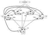
- FIG. 1is a high-level block diagram that illustrates the use of four ground transmitters for implementing a precise positioning solution, according to certain embodiments.
- FIG. 1shows a satellite 102 , four ground transmitters 104 a , 104 b , 104 c , 104 d and a rover 106 .
- each ground transmitteris equipped with a corresponding GPS receiver ( 108 a - d ), a corresponding transmitter ( 110 a - d ) and a corresponding wireless data link ( 112 a - d ).
- the wireless data linkis optional.
- Rover 106can include a ground transmitter receiver 116 , an optional GPS receiver 114 , and an optional data link 118 .
- one of the ground transmittersis designated as a master ground transmitter.
- the master ground transmitteris placed at a pre-surveyed location. Unlike a base station, the master ground transmitter transmits ranging signals to the rover. A base station does not transmit ranging signals.
- one of the ground transmittersis designated as a master ground transmitter
- the other ground transmittersare surveyed relative to the master ground transmitter at an accuracy level that is within one centimeter, using a GPS RTK survey, for example.
- the ground transmittersmay attain accurate one-centimeter survey locations by finding an optimal-fit solution to a collection of independent coarse position measurements, each coarse position measurement being a non-RTK position measurement of a ground transmitter and being much less accurate than one-centimeter.
- the GPS satellite 102transmits ranging signals that can be received by each of the ground transmitters for calculating a corresponding transmitter clock model. Each ground transmitter can transmit a ranging signal with code modulation. The implementation of a precise positioning solution is described in greater detail herein with reference to FIG. 2 .
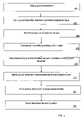
- FIG. 2is a flowchart that illustrates some high-level steps for implementing a precise positioning solution, according to certain embodiments.
- FIG. 2is described with reference to a master ground transmitter.
- four or more ground transmittersare deployed for a 3-D positioning system, assuming that there is access to ranging signals from at least one satellite.
- One of the ground transmittersis designated as a master ground transmitter according to certain embodiments.
- the number of ground transmitterscan vary from one to three and the corresponding number of satellites can vary from two to none.
- the master ground transmitteris deployed at a known location that is pre-surveyed in global coordinates, as a non-limiting example.
- GPS RTKthe location of each of the other ground transmitters can be surveyed relative to the master ground transmitter.
- the precise RTK-level GPS time reference ( ⁇ GPS )can be resolved.
- each ground transmittertransmits a wideband navigational signal, according to certain non-limiting embodiments.
- a wideband navigational signalis a ranging signal of any carrier frequency modulated by a wideband code.
- the carrier frequencyis typically 1 GHz or more.
- the wideband codehas a chipping rate that is fast enough to resolve carrier-phase integer biases. As a non-limiting example, the chipping rate is 30 MHz or faster.
- the wideband navigational signals (ranging signals) transmitted by the ground transmittersare received by a rover associated with a user who is interested in determining the user's precise position.
- the rovermeasures the carrier and code phases based on the ranging signals from the ground transmitters. It is assumed the phase measurements (also referred to as raw data) are corrected for known line biases for calculating clock models and the position solution. The line biases may be pre-calibrated quantities, for example.
- each ground transmittergenerates a corresponding transmitter clock model ( ⁇ circumflex over ( ⁇ ) ⁇ GTi ).
- the transmitter clock modelis also referred to herein as processed data because it derives from raw data such as phase measurements.
- FIG. 3is a block diagram that illustrates a clock model that uses a GPS time reference.
- FIG. 3shows a satellite 320 transmitting the GPS reference time ( ⁇ GPS ) to ground transmitter 322 .
- each of the ground transmitterscommunicates its corresponding generated clock model to the master ground transmitter, as described herein with reference to FIG. 4 and FIG. 5 .
- the generated clock modelsare communicated to the master ground transmitter via wireless datalinks.
- the master ground transmittercommunicates the set of clock models to the rover.
- the set of clock modelsis communicated to the rover via wireless datalinks, as described herein with reference to FIG. 4 .
- the set of clock modelsis communicated to the rover using a modulated data message on a ranging signal from the master ground transmitter, as described herein with reference to FIG. 5 .
- each of the ground transmittersinstead of communicating the clock models to the master ground transmitter, each of the ground transmitters communicates its corresponding generated clock model to the rover directly, as described herein with reference to FIG. 6 and FIG. 7 .
- ⁇ USER GTir USER GTi + ⁇ USER ⁇ ( ⁇ GPS + ⁇ circumflex over ( ⁇ ) ⁇ GTi )+ ⁇
- the roversolves the non-linear phase measurement equations to determine the user's position (X USER ,Y USER ,Z USER ) and the clock offset ( ⁇ USER )
- Four or more phase measurement equationscan be used to resolve the four unknowns, ⁇ USER , X USER ,Y USER , Z USER using a standard non-linear Least Squares estimate.
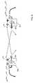
- FIG. 4is a block diagram that illustrates wireless datalink communications of clock models from the ground transmitters to the rover via the master ground transmitter.
- FIG. 4shows ground transmitters 402 , 404 , 406 , 408 and a rover 410 .
- Each ground transmitterhas a corresponding wireless datalink, such as a wireless modem, 402 a , 404 a , 406 a , and 408 a .
- Rover 410has a wireless datalink 410 a .
- Each ground transmittercommunicates its corresponding clock model to the master ground transmitter using the wireless datalinks.
- the master ground transmitterin turn, communicates the set of clock models to the rover using wireless datalinks.
- FIG. 5is a block diagram that illustrates communication of clock models from the ground transmitters to the master ground transmitter using wireless datalinks and communication from the master ground transmitter to the rover using a modulated data message on a ranging signal from the master ground transmitter.
- FIG. 5shows ground transmitters 502 , 504 , 506 , 508 and a rover 510 .
- Each ground transmitterhas a corresponding wireless datalink, such as a wireless modem, 502 a , 504 a , 506 a , and 508 a .
- Master ground transmitter 502has a transmitter 502 b .
- Rover 510has a receiver 510 a .
- Each ground transmittercommunicates its corresponding clock model to the master ground transmitter using the wireless datalinks.
- the master ground transmittercommunicates the set of clock models to the rover using its transmitter 502 b .
- a modulated data message on a ranging signal from the master ground transmitteris transmitted by transmitter 502 b and received by rover 510 through receiver 510 a.
- FIG. 6is a block diagram that illustrates wireless datalink communications of clock models directly from the ground transmitters to the rover.
- FIG. 6shows ground transmitters 602 , 604 , 606 , 608 and a rover 610 .
- Each ground transmitterhas a corresponding wireless datalink, such as a wireless modem, 602 a , 604 a , 606 a , and 608 a .
- Rover 610has a wireless datalink 610 a .
- Each ground transmittercommunicates its corresponding clock model to the rover directly using its corresponding wireless datalink.
- FIG. 7is a block diagram that illustrates communication of clock models directly from the ground transmitters to the rover using a modulated data message on a corresponding ranging signal from each ground transmitter.
- FIG. 7shows ground transmitters 702 , 704 , 706 , 708 and a rover 710 .
- Each ground transmitterhas a corresponding transmitter, 702 a , 704 a , 706 a , and 708 a .
- Rover 710has a receiver 710 a .
- Each ground transmittercommunicates its corresponding clock model to the rover directly using its corresponding transmitters.
- the modulated data message on a ranging signal from each ground transmitteris transmitted by transmitters 702 a , 704 a , 706 a , 708 a , and received by rover 710 through receiver 710 a.
- a clock model that is not based on a GPS time referencemay be used.
- the ground transmittersreceive a ranging signal from the master ground transmitter and use the master ground transmitter clock as a time reference.
- the ground transmittersare equipped with ground transmitter receivers for receiving the master ground transmitter ranging signal.
- FIG. 8is a block diagram that illustrates a clock model based on a master ground transmitter clock.
- FIG. 8shows a master ground transmitter 820 transmitting the master ground transmitter clock ( ⁇ GTmaster ) to a ground transmitter 822 .
- centimeter-level accuracy in rangecan be achieved, for example, by GPS RTK in the pre-survey stage.
- a relative clock difference amongst the ground transmitterscan be used for generating a clock model.
- the ground transmittersneed not listen to a specific ground transmitter, such as the master ground transmitter for example, to obtain a common time source.
- a specific ground transmittersuch as the master ground transmitter for example
- FIG. 9is a block diagram that illustrates a clock model based on the relative clock difference amongst ground transmitters.
- FIG. 9shows ground transmitters 920 and 922 transmitting their relative clocks to each other.
- the collection of the relative clock modelsare conveyed to the rover associated with the user.
Landscapes
- Engineering & Computer Science (AREA)
- Radar, Positioning & Navigation (AREA)
- Remote Sensing (AREA)
- Computer Networks & Wireless Communication (AREA)
- Physics & Mathematics (AREA)
- General Physics & Mathematics (AREA)
- Position Fixing By Use Of Radio Waves (AREA)
Abstract
Description
φUSERGTi=rUSERGTi+τUSER−τGTi+ε
Δ{circumflex over (τ)}GTi=τGTi−τGPS
Therefore,
τGTi=τGPS+Δ{circumflex over (τ)}GTi
φUSERGTi=rUSERGTi+τUSER−(τGPS+Δ{circumflex over (τ)}GTi)+ε
Δ{circumflex over (τ)}GTi=τGTi−τGTmaster
Δ{circumflex over (τ)}GTij=τGTi−τGTj
Claims (19)
Priority Applications (1)
| Application Number | Priority Date | Filing Date | Title |
|---|---|---|---|
| US11/360,359US7511667B2 (en) | 2006-02-22 | 2006-02-22 | Precise local positioning systems using ground-based transmitters |
Applications Claiming Priority (1)
| Application Number | Priority Date | Filing Date | Title |
|---|---|---|---|
| US11/360,359US7511667B2 (en) | 2006-02-22 | 2006-02-22 | Precise local positioning systems using ground-based transmitters |
Publications (2)
| Publication Number | Publication Date |
|---|---|
| US20070194988A1 US20070194988A1 (en) | 2007-08-23 |
| US7511667B2true US7511667B2 (en) | 2009-03-31 |
Family
ID=38427643
Family Applications (1)
| Application Number | Title | Priority Date | Filing Date |
|---|---|---|---|
| US11/360,359Active2026-05-20US7511667B2 (en) | 2006-02-22 | 2006-02-22 | Precise local positioning systems using ground-based transmitters |
Country Status (1)
| Country | Link |
|---|---|
| US (1) | US7511667B2 (en) |
Cited By (6)
| Publication number | Priority date | Publication date | Assignee | Title |
|---|---|---|---|---|
| US20090121940A1 (en)* | 2007-11-13 | 2009-05-14 | Jonathan Ladd | System for determining position over a network |
| US20100149032A1 (en)* | 2006-03-30 | 2010-06-17 | Feller Walter J | System for determining position using two way time transfer signals |
| US8055288B2 (en) | 2007-11-02 | 2011-11-08 | Novatel Inc. | System and method for distributing accurate time and frequency over a network |
| US20120127032A1 (en)* | 2010-11-19 | 2012-05-24 | Mcclure John A | Portable base station network for local differential gnss corrections |
| US8558738B2 (en) | 2008-05-22 | 2013-10-15 | Novatel Inc. | GNSS receiver using signals of opportunity and assistance information to reduce the time to first fix |
| CN108933750A (en)* | 2018-06-15 | 2018-12-04 | 北京遥测技术研究所 | A kind of distance measuring method based on Combined estimator, device and recording medium |
Families Citing this family (3)
| Publication number | Priority date | Publication date | Assignee | Title |
|---|---|---|---|---|
| US20100066603A1 (en)* | 2008-09-15 | 2010-03-18 | O'keefe Kyle | System and Methods for Real Time Kinematic Surveying Using GNSS and Ultra Wideband Ranging |
| US9285450B2 (en) | 2012-09-27 | 2016-03-15 | Google Inc. | Balloon-based positioning system and method |
| CN104483691B (en)* | 2015-01-05 | 2017-05-31 | 中国科学院重庆绿色智能技术研究院 | A kind of GNSS combines accurate one-point positioning method |
Citations (23)
| Publication number | Priority date | Publication date | Assignee | Title |
|---|---|---|---|---|
| US3715758A (en)* | 1969-07-10 | 1973-02-06 | Prakla Gmbh | Methods and apparatus for precise positioning of locations |
| US3883873A (en)* | 1972-10-19 | 1975-05-13 | Evgeny Alexandrovich Mosyakov | Method of unambiguous detecting the position of moving object, also ground station and receiver display of radio navigation system for effecting same |
| US5774829A (en)* | 1995-12-12 | 1998-06-30 | Pinterra Corporation | Navigation and positioning system and method using uncoordinated beacon signals in conjunction with an absolute positioning system |
| US5995043A (en)* | 1996-12-06 | 1999-11-30 | The Boeing Company | Aircraft satellite navigation precision-approach system including CDMA datalink |
| WO1999063358A1 (en) | 1998-05-29 | 1999-12-09 | Q Communications Pty. Ltd. | A method and device for creating a network positioning system (nps) |
| US6121928A (en)* | 1998-08-18 | 2000-09-19 | Trimble Navigation Limited | Network of ground transceivers |
| US6473032B1 (en)* | 2001-03-18 | 2002-10-29 | Trimble Navigation, Ltd | Network of non-cooperative integrated pseudolite/satellite base station transmitters |
| US6531981B1 (en)* | 2000-05-01 | 2003-03-11 | Skynetix, Llc | Global augmentation to global positioning system |
| US20030058163A1 (en)* | 2000-01-24 | 2003-03-27 | Integrinautics Corporation, A California Corporation | Carrier-based differential-position determination using multi-frequency pseudolites |
| US20040088111A1 (en)* | 2002-11-01 | 2004-05-06 | Honeywell International Inc. | Apparatus for improved integrity of wide area differential satellite navigation systems |
| US20040119638A1 (en)* | 2002-09-25 | 2004-06-24 | Fagan John E. | Navigation system using locally augmented GPS |
| US20050001742A1 (en)* | 2001-11-02 | 2005-01-06 | David Small | Method and device for chronologically synchronizing a location network |
| WO2005012935A1 (en) | 2003-08-05 | 2005-02-10 | Locata Corporation | A system and method for provinding assistance data within a location network |
| US20050089128A1 (en)* | 2003-10-27 | 2005-04-28 | Mcreynolds Stephen R. | Stable composite clock |
| US20050242995A1 (en)* | 2004-03-30 | 2005-11-03 | Thales | Method for the blind wideband localization of one or more transmitters from a carrier that is passing by |
| US6963304B2 (en)* | 2001-10-05 | 2005-11-08 | The Boeing Company | Method and apparatus for providing an integrated communications, navigation and surveillance satellite system |
| US20060022873A1 (en) | 2004-07-30 | 2006-02-02 | Integrinautics Corporation | Synchronizing ranging signals in an asynchronous ranging or position system |
| US20060022869A1 (en) | 2004-07-30 | 2006-02-02 | Integirnautics Corporation | Analog decorrelation of ranging signals |
| US20060022871A1 (en) | 2004-07-30 | 2006-02-02 | Integrinautics Corporation | Land-based transmitter position determination |
| US20060022870A1 (en) | 2004-07-30 | 2006-02-02 | Integrinautics Corporation | Land-based local ranging signal methods and systems |
| US20060022872A1 (en) | 2004-07-30 | 2006-02-02 | Integrinautics Corporation | Asynchronous local position determination system and method |
| US20070040744A1 (en)* | 2004-07-30 | 2007-02-22 | Integrinautics Corporation | Satellite and local system position determination |
| US20070063896A1 (en)* | 2005-09-20 | 2007-03-22 | Novariant Inc. | Troposphere corrections for ground based positioning systems |
- 2006
- 2006-02-22USUS11/360,359patent/US7511667B2/enactiveActive
Patent Citations (24)
| Publication number | Priority date | Publication date | Assignee | Title |
|---|---|---|---|---|
| US3715758A (en)* | 1969-07-10 | 1973-02-06 | Prakla Gmbh | Methods and apparatus for precise positioning of locations |
| US3883873A (en)* | 1972-10-19 | 1975-05-13 | Evgeny Alexandrovich Mosyakov | Method of unambiguous detecting the position of moving object, also ground station and receiver display of radio navigation system for effecting same |
| US5774829A (en)* | 1995-12-12 | 1998-06-30 | Pinterra Corporation | Navigation and positioning system and method using uncoordinated beacon signals in conjunction with an absolute positioning system |
| US5995043A (en)* | 1996-12-06 | 1999-11-30 | The Boeing Company | Aircraft satellite navigation precision-approach system including CDMA datalink |
| WO1999063358A1 (en) | 1998-05-29 | 1999-12-09 | Q Communications Pty. Ltd. | A method and device for creating a network positioning system (nps) |
| US6449558B1 (en)* | 1998-05-29 | 2002-09-10 | David Anthony Small | Method and device for creating a network positioning system (NPS) |
| US6121928A (en)* | 1998-08-18 | 2000-09-19 | Trimble Navigation Limited | Network of ground transceivers |
| US20030058163A1 (en)* | 2000-01-24 | 2003-03-27 | Integrinautics Corporation, A California Corporation | Carrier-based differential-position determination using multi-frequency pseudolites |
| US6531981B1 (en)* | 2000-05-01 | 2003-03-11 | Skynetix, Llc | Global augmentation to global positioning system |
| US6473032B1 (en)* | 2001-03-18 | 2002-10-29 | Trimble Navigation, Ltd | Network of non-cooperative integrated pseudolite/satellite base station transmitters |
| US6963304B2 (en)* | 2001-10-05 | 2005-11-08 | The Boeing Company | Method and apparatus for providing an integrated communications, navigation and surveillance satellite system |
| US20050001742A1 (en)* | 2001-11-02 | 2005-01-06 | David Small | Method and device for chronologically synchronizing a location network |
| US20040119638A1 (en)* | 2002-09-25 | 2004-06-24 | Fagan John E. | Navigation system using locally augmented GPS |
| US20040088111A1 (en)* | 2002-11-01 | 2004-05-06 | Honeywell International Inc. | Apparatus for improved integrity of wide area differential satellite navigation systems |
| WO2005012935A1 (en) | 2003-08-05 | 2005-02-10 | Locata Corporation | A system and method for provinding assistance data within a location network |
| US20050089128A1 (en)* | 2003-10-27 | 2005-04-28 | Mcreynolds Stephen R. | Stable composite clock |
| US20050242995A1 (en)* | 2004-03-30 | 2005-11-03 | Thales | Method for the blind wideband localization of one or more transmitters from a carrier that is passing by |
| US20060022873A1 (en) | 2004-07-30 | 2006-02-02 | Integrinautics Corporation | Synchronizing ranging signals in an asynchronous ranging or position system |
| US20060022869A1 (en) | 2004-07-30 | 2006-02-02 | Integirnautics Corporation | Analog decorrelation of ranging signals |
| US20060022871A1 (en) | 2004-07-30 | 2006-02-02 | Integrinautics Corporation | Land-based transmitter position determination |
| US20060022870A1 (en) | 2004-07-30 | 2006-02-02 | Integrinautics Corporation | Land-based local ranging signal methods and systems |
| US20060022872A1 (en) | 2004-07-30 | 2006-02-02 | Integrinautics Corporation | Asynchronous local position determination system and method |
| US20070040744A1 (en)* | 2004-07-30 | 2007-02-22 | Integrinautics Corporation | Satellite and local system position determination |
| US20070063896A1 (en)* | 2005-09-20 | 2007-03-22 | Novariant Inc. | Troposphere corrections for ground based positioning systems |
Non-Patent Citations (9)
| Title |
|---|
| Barnes, J., et al., "High Precision Indoor and Outdoor Positioning using LocataNet," School of Surveying and Spatial Information Systems, The University of New South Wales, Australia (UNSW). |
| Barnes, J., et al., "Locata: a New Positioning Technology for High Precision Indoor and Outdoor Positioning," School of Surveying and Spatial Information Systems, The University of New South Wales, Australia (UNSW). |
| Barnes, J., et al., "LocataNet: Intelligent time-synchronised pseudolite transceivers for cm-level stand-alone positioning," Satellite Navigation and Positioning (SNAP) Group, School of Surveying and Spatial Information Systems, The University of New South Wales, Australia (UNSW). |
| LeMaster, E.Al, "Self-Calibrating Pseudolite Arrays: Theory and Experiment," A dissertation submitted to the Department of Aeronautics and Astronautics, (May 2002). |
| Matsuoka, M., "Mars Rover Navigation Using Pseudolite Transceiver Arrays: Network-Based Ranging and Extended Self-Calibration Algorithm," A dissertation submitted to the Department of Aeronautics and Astronautics (Mar. 2005). |
| Trimbel News Release, entitled Trimble Introduces New Surveying Products For the Connected Survey Site, (Oct. 2005). |
| U.S. Appl. No. 10/909,140, filed Jul. 30, 2004, Bauregger et al. |
| U.S. Appl. No. 10/909,184, filed Jul. 30, 2004, Zimmerman et al. |
| U.S. Appl. No. 10/909,243, filed Jul. 30, 2004, Zimmerman et al. |
Cited By (13)
| Publication number | Priority date | Publication date | Assignee | Title |
|---|---|---|---|---|
| US20100149032A1 (en)* | 2006-03-30 | 2010-06-17 | Feller Walter J | System for determining position using two way time transfer signals |
| US8159397B2 (en) | 2006-03-30 | 2012-04-17 | Novatel Inc. | System for determining position using two way time transfer signals |
| US8055288B2 (en) | 2007-11-02 | 2011-11-08 | Novatel Inc. | System and method for distributing accurate time and frequency over a network |
| US8085201B2 (en) | 2007-11-13 | 2011-12-27 | Novatel Inc. | System for determining position over a network |
| US20090121940A1 (en)* | 2007-11-13 | 2009-05-14 | Jonathan Ladd | System for determining position over a network |
| US8558738B2 (en) | 2008-05-22 | 2013-10-15 | Novatel Inc. | GNSS receiver using signals of opportunity and assistance information to reduce the time to first fix |
| WO2011072368A1 (en)* | 2009-12-17 | 2011-06-23 | Novatel Inc. | System for determining position using two way time transfer signals |
| US20120127032A1 (en)* | 2010-11-19 | 2012-05-24 | Mcclure John A | Portable base station network for local differential gnss corrections |
| US8803735B2 (en)* | 2010-11-19 | 2014-08-12 | Agjunction Llc | Portable base station network for local differential GNSS corrections |
| US9903953B2 (en) | 2010-11-19 | 2018-02-27 | Agjunction Llc | Portable base station network for local differential GNSS corrections |
| US10571576B2 (en) | 2010-11-19 | 2020-02-25 | Agjunction Llc | Portable base station network for local differential GNSS corrections |
| CN108933750A (en)* | 2018-06-15 | 2018-12-04 | 北京遥测技术研究所 | A kind of distance measuring method based on Combined estimator, device and recording medium |
| CN108933750B (en)* | 2018-06-15 | 2021-03-26 | 北京遥测技术研究所 | Distance measurement method and device based on joint estimation and recording medium |
Also Published As
| Publication number | Publication date |
|---|---|
| US20070194988A1 (en) | 2007-08-23 |
Similar Documents
| Publication | Publication Date | Title |
|---|---|---|
| CN110031881B (en) | Method for assisting precise point positioning by high-precision inter-satellite laser ranging | |
| US7511667B2 (en) | Precise local positioning systems using ground-based transmitters | |
| US11705936B2 (en) | Wide area positioning system | |
| US7576690B2 (en) | Position determination with reference data outage | |
| EP1660904B1 (en) | A system and method for provinding assistance data within a location network | |
| US7616682B2 (en) | Method and device for chronologically synchronizing a location network | |
| AU2012275282B2 (en) | Coding in a wide area positioning system (WAPS) | |
| US7489270B2 (en) | GNSS line bias measurement system and method | |
| AU2002336808A1 (en) | A method and device for chronologically synchronizing a location network | |
| JPH09503058A (en) | Retransmission Navigation system using GPS | |
| US7468697B2 (en) | Self-surveying wideband ground transmitters | |
| US7292188B2 (en) | Apparatus and method for CDMA time pseudolite for repeater identification | |
| RU2825248C1 (en) | Method of locating user terminals moving in coverage area of local navigation system | |
| AU2006202938B2 (en) | Frequency Coherence within a Location Network | |
| AU2006202937B2 (en) | Locating a Roving Position Receiver within a Location Network |
Legal Events
| Date | Code | Title | Description |
|---|---|---|---|
| AS | Assignment | Owner name:NOVARIANT, INC., CALIFORNIA Free format text:ASSIGNMENT OF ASSIGNORS INTEREST;ASSIGNORS:MATSUOKA, MASAYOSHI;ZIMMERMAN, KURT R.;MONTGOMERY, PAUL Y.;AND OTHERS;REEL/FRAME:017612/0786;SIGNING DATES FROM 20060221 TO 20060222 | |
| AS | Assignment | Owner name:ORIX VENTURE FINANCE LLC,VIRGINIA Free format text:SECURITY AGREEMENT;ASSIGNOR:NOVARIANT, INC.;REEL/FRAME:018442/0556 Effective date:20061024 Owner name:ORIX VENTURE FINANCE LLC, VIRGINIA Free format text:SECURITY AGREEMENT;ASSIGNOR:NOVARIANT, INC.;REEL/FRAME:018442/0556 Effective date:20061024 | |
| STCF | Information on status: patent grant | Free format text:PATENTED CASE | |
| AS | Assignment | Owner name:SILICON VALLEY BANK,CALIFORNIA Free format text:SECURITY AGREEMENT;ASSIGNOR:NOVARIANT, INC.;REEL/FRAME:024358/0501 Effective date:20100510 Owner name:SILICON VALLEY BANK, CALIFORNIA Free format text:SECURITY AGREEMENT;ASSIGNOR:NOVARIANT, INC.;REEL/FRAME:024358/0501 Effective date:20100510 | |
| AS | Assignment | Owner name:NOVARIANT, INC.,CALIFORNIA Free format text:RELEASE BY SECURED PARTY;ASSIGNOR:ORIX VENTURE FINANCE, LLC;REEL/FRAME:024380/0678 Effective date:20100510 | |
| AS | Assignment | Owner name:NOVARIANT, INC., CALIFORNIA Free format text:RELEASE BY SECURED PARTY;ASSIGNOR:SILICON VALLEY BANK;REEL/FRAME:025114/0197 Effective date:20101008 | |
| AS | Assignment | Owner name:TRIMBLE NAVIGATION LIMITED, CALIFORNIA Free format text:ASSIGNMENT OF ASSIGNORS INTEREST;ASSIGNOR:NOVARIANT, INC.;REEL/FRAME:025238/0251 Effective date:20101008 | |
| AS | Assignment | Owner name:NOVARIANT, INC., CALIFORNIA Free format text:RELEASE;ASSIGNOR:SILICON VALLEY BANK;REEL/FRAME:027400/0587 Effective date:20111207 | |
| FPAY | Fee payment | Year of fee payment:4 | |
| AS | Assignment | Owner name:NOVARIANT, INC., CALIFORNIA Free format text:RELEASE;ASSIGNOR:SILICON VALLEY BANK;REEL/FRAME:033972/0405 Effective date:20140922 | |
| FEPP | Fee payment procedure | Free format text:PAT HOLDER NO LONGER CLAIMS SMALL ENTITY STATUS, ENTITY STATUS SET TO UNDISCOUNTED (ORIGINAL EVENT CODE: STOL); ENTITY STATUS OF PATENT OWNER: LARGE ENTITY | |
| FEPP | Fee payment procedure | Free format text:PAT HOLDER CLAIMS SMALL ENTITY STATUS, ENTITY STATUS SET TO SMALL (ORIGINAL EVENT CODE: LTOS); ENTITY STATUS OF PATENT OWNER: LARGE ENTITY Free format text:PAYOR NUMBER ASSIGNED (ORIGINAL EVENT CODE: ASPN); ENTITY STATUS OF PATENT OWNER: LARGE ENTITY Free format text:PAYER NUMBER DE-ASSIGNED (ORIGINAL EVENT CODE: RMPN); ENTITY STATUS OF PATENT OWNER: LARGE ENTITY | |
| FEPP | Fee payment procedure | Free format text:PAT HOLDER NO LONGER CLAIMS SMALL ENTITY STATUS, ENTITY STATUS SET TO UNDISCOUNTED (ORIGINAL EVENT CODE: STOL); ENTITY STATUS OF PATENT OWNER: LARGE ENTITY | |
| FPAY | Fee payment | Year of fee payment:8 | |
| MAFP | Maintenance fee payment | Free format text:PAYMENT OF MAINTENANCE FEE, 12TH YEAR, LARGE ENTITY (ORIGINAL EVENT CODE: M1553); ENTITY STATUS OF PATENT OWNER: LARGE ENTITY Year of fee payment:12 |