US7510126B2 - HVAC communication system - Google Patents
HVAC communication systemDownload PDFInfo
- Publication number
- US7510126B2 US7510126B2US11/567,626US56762606AUS7510126B2US 7510126 B2US7510126 B2US 7510126B2US 56762606 AUS56762606 AUS 56762606AUS 7510126 B2US7510126 B2US 7510126B2
- Authority
- US
- United States
- Prior art keywords
- communication
- usage
- hvac
- coupled
- thermostat
- Prior art date
- Legal status (The legal status is an assumption and is not a legal conclusion. Google has not performed a legal analysis and makes no representation as to the accuracy of the status listed.)
- Expired - Fee Related, expires
Links
Images


Classifications
- F—MECHANICAL ENGINEERING; LIGHTING; HEATING; WEAPONS; BLASTING
- F24—HEATING; RANGES; VENTILATING
- F24F—AIR-CONDITIONING; AIR-HUMIDIFICATION; VENTILATION; USE OF AIR CURRENTS FOR SCREENING
- F24F11/00—Control or safety arrangements
- F24F11/30—Control or safety arrangements for purposes related to the operation of the system, e.g. for safety or monitoring
- F24F11/32—Responding to malfunctions or emergencies
- F24F11/33—Responding to malfunctions or emergencies to fire, excessive heat or smoke
- F—MECHANICAL ENGINEERING; LIGHTING; HEATING; WEAPONS; BLASTING
- F24—HEATING; RANGES; VENTILATING
- F24F—AIR-CONDITIONING; AIR-HUMIDIFICATION; VENTILATION; USE OF AIR CURRENTS FOR SCREENING
- F24F11/00—Control or safety arrangements
- F24F11/30—Control or safety arrangements for purposes related to the operation of the system, e.g. for safety or monitoring
- F24F11/46—Improving electric energy efficiency or saving
- F24F11/47—Responding to energy costs
- F—MECHANICAL ENGINEERING; LIGHTING; HEATING; WEAPONS; BLASTING
- F24—HEATING; RANGES; VENTILATING
- F24F—AIR-CONDITIONING; AIR-HUMIDIFICATION; VENTILATION; USE OF AIR CURRENTS FOR SCREENING
- F24F11/00—Control or safety arrangements
- F24F11/50—Control or safety arrangements characterised by user interfaces or communication
- F24F11/56—Remote control
- F—MECHANICAL ENGINEERING; LIGHTING; HEATING; WEAPONS; BLASTING
- F24—HEATING; RANGES; VENTILATING
- F24F—AIR-CONDITIONING; AIR-HUMIDIFICATION; VENTILATION; USE OF AIR CURRENTS FOR SCREENING
- F24F11/00—Control or safety arrangements
- F24F11/62—Control or safety arrangements characterised by the type of control or by internal processing, e.g. using fuzzy logic, adaptive control or estimation of values
- F24F11/63—Electronic processing
- F—MECHANICAL ENGINEERING; LIGHTING; HEATING; WEAPONS; BLASTING
- F24—HEATING; RANGES; VENTILATING
- F24F—AIR-CONDITIONING; AIR-HUMIDIFICATION; VENTILATION; USE OF AIR CURRENTS FOR SCREENING
- F24F11/00—Control or safety arrangements
- F24F11/88—Electrical aspects, e.g. circuits
Definitions
- This inventionrelates generally to a communication system for a single-wire interface, and more particularly to a communication system capable of communicating between, for example, a thermostat and a receiving unit disposed near or in an air compressor by way of high frequency current modulation along a single HVAC control wire.
- variable rate plansmay offer customers variable rate plans. Under these variable rate plans, a consumer may pay A cents per unit for energy at 10 AM, B cents per unit at 2 PM, and C cents per unit at 11 PM. Further, some utilities offer cost advantages to consumers who allow the energy provider to override their programmed thermostat settings at peak demand times to help prevent brownouts and blackouts.
- HVACheating, ventilation and air conditioning
- An alternate solutionis to equip a thermostat with a wireless communication system.
- the problem with this solutionis that such a wireless connection requires more power than can be sourced by the 24-volt wire running to the thermostat. Consequently, additional wiring must still be provided to supply power to the communication device. Again, installation of additional wiring into existing structures may be cost prohibitive. While a battery may be used to power the wireless communication system, the user must take care to ensure that the batteries are continually replaced, which is inconvenient and costly. Further complicating matters, reception problems may exist with wireless systems due to interior walls and signal multipaths.
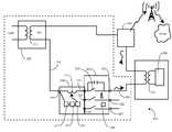
- FIG. 1illustrates a system for communication across HVAC wiring in accordance with the invention.
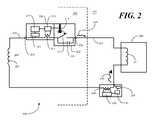
- FIG. 2illustrates an alternate embodiment of a system for communication across HVAC wiring in accordance with the invention.
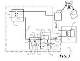
- FIG. 3illustrates an alternate embodiment of a system for communication across HVAC wiring in accordance with the invention.
- FIG. 4illustrates a method of communication across HVAC wiring in accordance with the invention.
- FIG. 5illustrates a system for communication across a HVAC wiring, the system being equipped with PLC communication capability, in accordance with the invention.
- embodiments of the invention described hereinmay be comprised of one or more conventional processors and unique stored program instructions that control the one or more processors to implement, in conjunction with certain non-processor circuits, some, most, or all of the functions of communication across conventional HVAC wiring described herein.
- the non-processor circuitsmay include, but are not limited to, signal transformers, radio-frequency modulators, signal drivers, clock circuits, power source circuits, and user input devices. As such, these functions may be interpreted as steps of a method to perform communication across HVAC wiring.
- some or all functionscould be implemented by a state machine that has no stored program instructions, or in one or more application specific integrated circuits (ASICs), in which each function or some combinations of certain of the functions are implemented as custom logic.
- ASICsapplication specific integrated circuits
- the present inventionoffers a system and method for providing a reliable communication link between a HVAC control unit disposed within a building, like a thermostat for example, and a HVAC load disposed outside, like an air conditioning compressor for example.
- conventional HVAC system wiringprovides only a single wire from the thermostat to the compressor.
- the present inventionuses high-frequency current modulation across this single wire to provide a communication channel from the interior to the exterior of the building.
- the present inventionallows reliable, low-loss communication signals in excess of 4800 baud between thermostat, compressor or air handler as required.
- a currentis injected into or induced upon the connection running between thermostat and compressor by way of a serially coupled, small signal transformer.
- the induced currentis modulated with a RF signal.
- the modulation signalhas a frequency of between 5 and 50 MHz.
- the frequencyis 21.4 MHz
- the RF-modulated current signalis modulated by narrow band frequency shift keying (FSK) with a 4800-baud packet.
- FSKnarrow band frequency shift keying
- the RF signal modulated onto the current waveformflows around the HVAC system in a continuous current loop. For example: a current induced on the compressor wire at the thermostat will flow along the wire to the coil winding of a contactor coupled to the compressor.
- the frequency of modulationis selected such that the signal flows through the parasitic inter-winding capacitance of the wire turns in the coil.
- the RF signal modulated onto the induced current waveformis generally unfiltered and unaltered as it passes through the current loop.
- the signalAfter passing through the parasitic capacitance of the contactor coil, the signal is received by a second, serially coupled, small signal transformer in a receiver.
- the receiverin one embodiment, is disposed outside the building and includes a narrow band RF receiver.
- the signalthen continues to the class II, 24-volt system power transformer, which may be disposed at, near or in the air handler. Again, as with the compressor, the high-frequency signal is able to pass about the large inductance of the power transformer coil by coupling through the parasitic capacitance of the wire turns in the transformer.
- the signalthen continues back to the communication module where it originated. Thus, a full loop is completed. While in one embodiment described below one communication device and one receiver are employed, it will be clear to one of ordinary skill in the art having the benefit of this disclosure that the invention is not so limited. Any number of communication devices and receivers may be coupled serially in the HVAC loop, regardless of location.
- FIG. 1illustrated therein is one embodiment of a system 100 for communicating across a single HVAC control wire 101 .
- the system 100may use the single wire 101 coupling a HVAC control unit 102 , such as an electronic thermostat, with a HVAC load unit 103 , such as an air compressor, to transmit communication signals 104 from inside 106 a building 105 to the exterior 107 of the building 105 .
- a HVAC control unit 102such as an electronic thermostat
- HVAC load unit 103such as an air compressor
- a communication device 108suitable for connection to the HVAC control unit 102 , is capable of inducing a modulated communication signal 104 onto any of the conventional wires coupling the control unit 102 with the load devices, e.g. 103 .
- One wire that is of particular utilityis the cooling control wire shown as element 101 , as this wire 101 runs directly from the thermostat (disposed inside in conventional HVAC systems) to the air compressor (disposed outside in conventional HVAC systems).
- a receiver 109which may be disposed near, in, or at the HVAC load unit 103 , is capable of receiving the communication signal current 104 .
- bi-directional communication between the communication device 108 and the receiver 109is desirable.
- an energy providermay wish to retrieve demand or other data from the thermostat coupled to the communication device 108 while also uploading new pricing information.
- the receiver 109is configured so as to be capable of inducing a second communication signal current waveform 110 onto the HVAC control wire 101 , thereby acting as a transceiver.
- the first communication signal 104transmits data from the communication device 108 to the receiver 109
- the second communication signal 110transmits data from the receiver 109 to the communication device 108 .
- both the communication device 108 and the receiver 109may transmit and receive signals.
- the communication signals 104 , 110comprise a frequency modulated current having a frequency of between 5 and 50 MHz. This frequency is selected such that the signals 104 , 110 are able to pass through large coils, e.g. contactor coil 111 , in load devices, e.g. 103 , by way of the inherent, parasitic capacitance formed by the closely wound wires in the coils (or transformer windings where present).
- the frequency selectionallows the communication module 108 and receiver 109 to be placed at any point in the system, regardless of the location of transformers or other coils. For instance, in FIG. 1 , the HVAC load unit 103 and its actuation contactor coil 111 are disposed serially between the communication module 108 and the receiver 109 .
- a communication system in accordance with the inventionis retrieving and delivering information to and from an electronic thermostat in a HVAC system
- the communication device 108will be directly coupled to the control unit 102 (i.e. the thermostat).
- the control unit 102i.e. the thermostat
- signals conducted across the control wire 101will pass through the thermostat (since the control wire 101 and connecting paths run in a current loop).
- the thermostatwill contain at least one HVAC load switch 112 capable of actuating the HVAC load unit 103 when closed.
- the communication device 108transmits the signals 104 , 110 through this bypass capacitor when the switch 112 is open.
- the 24-volt sourceis coupled in parallel with the bypass capacitor 113 (effectively shorting the capacitor 113 ) to the HVAC control wire 101 .
- the closed switch 112thereby delivers a high-current control signal to the HVAC control wire 101 to actuate the HVAC load unit 102 .
- the communication device 108when the switch 112 is open, the communication device 108 must ensure that the power of the signals 104 , 110 is not large enough to actuate the HVAC load unit 102 . In other words, the power of the signals 104 , 110 must be limited so as not to inadvertently cause the HVAC load unit to inadvertently turn on.
- the communication signals 104 , 110comprise a frequency modulated signal imposed on a current waveform having a peak value that remains below a predetermined switch threshold, the predetermined switch threshold corresponding to a level capable of actuating a HVAC load switch in the HVAC control unit.
- control unit 102has been described as a thermostat, and the HVAC load unit 103 has been described as an air compressor. It will be clear to those of ordinary skill in the art having the benefit of this disclosure, however, that the invention is not so limited.
- the control unit 102may be any type of device capable of affecting the performance of the overall HVAC system.
- One examplewould be a smoke detector that, for instance, turns off the furnace when smoke is detected.
- the HVAC load device 103may be any of an air conditioning compressor, a compressor, an air handler, heat pump, humidifier, furnace, or other devices. Further, the communication system could be used to control these devices.
- FIG. 2illustrated therein is another embodiment of a HVAC communication system 200 in accordance with the invention.
- the system 200includes a communication device 208 suitable for coupling to an electronic thermostat 202 .
- the electronic thermostat 202has four contacts suitable for coupling to conventional HVAC wiring (i.e. a low-voltage power wire, a heating control wire, a cooling control wire and a fan control wire).
- the communication device 208includes a control module 215 and a communication module 208 coupled to the control module 215 .
- the control module 215comprises a microprocessor capable of executing instructions from an embedded code.
- the control module 215serves as the central processing unit in the operation of the communication device 208 .
- the control module 215is coupled to the thermostat 202 so as to be able to transmit and receive data from data circuitry in the thermostat 202 .
- the communication module 208is configured to communicate through the HVAC system by way of a small signal communication transformer 213 coupled serially with a control wire 201 running from the thermostat 202 to a load 203 .
- the control wire 201may be any of the heating control wire, fan control wire or cooling control wire, for simplicity of discussion the control wire 201 shown in FIG. 2 is chosen to be the cooling control wire, which is a single wire running from a control terminal 222 of the thermostat 202 to a contactor coil 211 or other device disposed within the load 203 . This will be a preferred selection of many installations, as the air compressor 203 is disposed outside 207 a building 205 , while the thermostat 202 is disposed inside 206 .
- the compressor 203in conventional systems, includes a contactor coil 211 with which the thermostat 202 turns on the air conditioning system.
- the frequency of the communication signal 204is selected so as to easily be transferred across the parasitic capacitances of the transformer or coil windings.
- the signal 204has a frequency of between 4 and 50 MHz.
- the communication module 214includes a communication transformer 213 that is coupled serially between the control module 215 and the air compressor 203 .
- Radio frequency communication circuitry 214 disposed within the communication module 214induces low-power current signals 204 , 210 into the control wire 201 by way of the communication transformer 213 .
- digital control and data communication signalsmay be transmitted from the thermostat 202 to a receiver 209 and vice versa.
- the system 200includes a thermal sensing element 217 coupled to the control module 215 .
- the thermal sensing element 217may be the temperature sensor residing in the thermostat 202 .
- the system 200also includes at least one switch 212 responsive to the thermal sensing element 217 .
- the switch 212may be any of the heating control switch, the fan control switch and the cooling control switch found in a conventional thermostat.
- the communication device 208itself may include a serially coupled switch (not shown) that would, in effect, override the thermostat switches.
- the switch 212is the cooling control switch of the thermostat 202 . When the switch 212 is closed, the switch 212 actuates the load 203 .
- bypass capacitordisposed about the switch that the communication device 208 employs for communication when the switch 212 is open.
- an AC loop for communicationexists regardless of the state of switch 212 .
- a parallel bypass capacitorwould be included about that switch as well.
- the low-voltage AC terminalis also coupled to the control module 215 by way of a power supply module 221 .
- the control modulemay operate in a “parasitic power” mode, wherein all power needed to operate the communication device 208 may be drawn from the low-voltage AC terminal 219 .
- a power supply module 221is coupled to the low-voltage AC input terminal 219 , and the power supply module 221 receives an amount of power from the low-voltage AC input terminal 219 sufficient to operate the control module 215 and the communication module 214 .
- Such operationprovides unique advantage in that no batteries or other power connections are required when installing the communication device 208 into a conventional HVAC system.
- the control module 215must take care not to draw so much power for the operation of the communication device 208 that the power supply transformer 220 becomes overloaded, thereby causing the 24V output voltage to droop. As such, the power drawn by the communication device 208 must remain below a predetermined threshold. Experimental results have shown that so long as the components of the communication device 208 draw no more than 55 mW, operation of most HVAC systems will not be affected by the presence of the communication device 208 . As such, in accordance with one embodiment of the invention, the total power drawn by the power supply module 221 for its operation and the operation of the control module 215 and communication module 214 remains below a predetermined threshold. In one embodiment, this predetermined threshold is 48 mW. Experimental testing has shown, however, that a predetermined threshold of 55 mW works in most all applications.
- a second communication device 209is provided for receiving signals 204 from the communication device 208 .
- the second communication device 209includes a second control module 216 and a second communication module 223 having a second communication transformer 224 coupled serially with the control wire 201 .
- the second communication device 209acts as a receiver for signals 204 sent by the communication device 208 , and is also capable of transmitting signals 210 to the communication device 208 .
- the control module 215actuates the communication module 214
- a communication signal 204is transmitted across the control wire 201 and is received by the second communication module 209 , and vice versa.
- a communication device 308has a plurality of terminals 319 , 330 , 324 , 325 configured to couple to a plurality of HVAC control wires 301 , 318 , 326 , 327 , either directly or through a thermostat 302 to which the communication device 308 is coupled.
- One of the terminalsis a low-voltage AC terminal 319 that is coupled to a power transformer 320 , such as the class II, 24V transformers found in conventional HVAC systems.
- Another terminalis a Y-line terminal 322 .
- the Y-line terminal 322is so called because in certain regions of the United States, a yellow wire is used as the cooling control wire 301 that runs directly from the thermostat to the air compressor 303 of the air conditioning system.
- a yellow wireis used as the cooling control wire 301 that runs directly from the thermostat to the air compressor 303 of the air conditioning system.
- the “yellow line” or “Y-line” and “Y-terminal”are recognized terms in the industry, they are used herein to refer to this control wire 301 . It is not intended that yellow be a limiting adjective in referring to this control wire 301 , rather it is simply a commonly used term to easily identify this control wire 301 . It will be clear to those of ordinary skill in the art that any color wire may be used. In fact, some areas of the country employ a blue color for this control wire 301 .
- a power supply 321is coupled to the low-voltage AC input terminal 319 for providing power to the communication device 308 .
- all power required to operate the communication device 308is drawn from this low-voltage AC input terminal, thereby allowing the device 308 to operate as a parasitic power device, where no external batteries or additional power sources are required.
- a control module 315is coupled to the power supply 321 .
- the control module 315which may be a microprocessor or programmable logic device, serves as the central processor of the device 308 .
- the air compressor 303may be turned on, at least one switch 312 is coupled to and controllable by the control module 315 .
- the switch 312When the switch 312 is closed, the low voltage AC terminal 319 is directly coupled to the Y-line terminal, such that the low voltge, 24-volt, AC input on the low-voltage AC power line 318 is passed through to the contactor coil 311 coupled to the air compressor 303 .
- the switch 312when the switch 312 is closed, power sufficient to actuate the air compressor is passed to the load, thereby causing it to actuate.
- the Y-line 301effectively makes an AC loop throughout the system 300 regardless of the state of switch 312 , thereby permitting the communication module 314 to communicate at all times.
- the Y-line 301runs from thermostat to the air compressor load 303 to the air handler 329 and back to the thermostat 302 .
- a communication module 314is coupled to the control module 315 between the compressor 303 and the air handler 329 .
- the control module 315delivers data to the communication module 314 , which in turn transmits the data by inducing a RF signal onto the Y-line 301 by way of a communication transformer 313 coupled to the communication module 314 .
- One winding of the communication transformer 313is coupled serially with the Y-line terminal 322 .
- the communication module 314includes circuitry configured to couple a communication signal to the communication transformer 313 .
- the communication modulemay modulate the communication signal with a carrier signal having a frequency of between 5 and 50 MHz.
- the frequencyshould be high enough so as to take advantage of the parasitic capacitance found in the transformer or coil windings of the load devices, but should not be so high as to create electromagnetic noise for surrounding systems. Since the Y-line 301 is coupled in a large loop about the HVAC system, it can act as a large antenna, thereby broadcasting certain signals to neighboring systems. Experimental results have shown that frequencies of between 8 and 12 MHz, between 18 and 25 MHz and between 44 and 46 MHz work well in providing signals with minimal loss across the HVAC system. One frequency well suited for easy manufacture of the RF circuitry in the communication module 314 is 21.4 MHz.
- the communication device 308is coupled to an electronic thermostat 302 .
- the communication device 314may in fact be disposed within a sub-base of the thermostat 302 .
- the communication device 308may be used to retrieve information from the thermostat 302 and to transmit it to, for example, an energy provider.
- the communication device 308may also receive one or more signals from the energy provider.
- the control module 315 of the communication device 308may therefore include a memory device for storing the information retrieved from the thermostat.
- the information monitored by the communication device 308may include operating characteristics of the thermostat such as total compressor usage, total furnace usage, total HVAC system usage, average compressor usage, average furnace usage, average HVAC system usage, peak compressor usage, peak furnace usage, peak HVAC system usage, time of compressor usage, time of furnace usage, time of HVAC system usage, cost of compressor usage, cost of furnace usage, cost of HVAC system usage, time of use schedule, temperature override information, hold override information, time of day information, diagnostic information, error messages, temperature profiling information, appliance control schedules, protocol handling messages, current HVAC operating modes, thermostat configuration flags, test commands and lockout commands.
- operating characteristics of the thermostatsuch as total compressor usage, total furnace usage, total HVAC system usage, average compressor usage, average furnace usage, average HVAC system usage, peak compressor usage, peak furnace usage, peak HVAC system usage, time of compressor usage, time of furnace usage, time of HVAC system usage, cost of compressor usage, cost of furnace usage, cost of HVAC system usage, time of use schedule, temperature override information, hold override information, time of day information, diagnostic information, error
- information about and/or relating to appliances connected to the HVAC systemmay be communicated across the HVAC system by the communication device 308 .
- the communication device 308may further communicate to the thermostat 302 information from an energy provider such as an energy rate or an override request.
- the thermostat 302may communicate to the communication device 308 information including a command signal for actuating the load, e.g. 303 , and temperature set point information.
- thermostatsmay be coupled to the communication device 308 .
- an environmental sensor 328like a smoke detector, hygrometer, motion sensor or other device may also be coupled to the communication device 308 .
- the communication devicemay be configured to monitor changes in environmental conditions such as temperature, humidity, smoke, light, audio, water level, weight, motion, pressure, electrical current, voltage, AC input frequency and chemical element presence. Where the change in environmental condition exceeded a predetermined threshold, the control module 315 may actuate the communication module 314 .
- the environmental sensor 328is a smoke detector
- the communication device 308may transmit a signal across the Y-line 301 out of the house to a receiver 309 . The receiver 309 would then be able to notify the proper emergency personnel.
- a second communication deviceis coupled serially with the Y-line 301 .
- the receiver 309is capable of detecting and receiving communication signals from the communication device 308 . Further, in bi-directional systems, the receiver 309 may operate as a transmitter by inducing modulated current into the Y-line as well.
- the communication device 308 and receiver 309are capable of handshaking to determine the proper amount of power with which to transmit communication signals. It is often desirable to transmit with the smallest amount of power that will reliably deliver data from transmitting module to receiving module. To do this, at least one of the communication module 308 and the receiver 309 may be configured to transmit a signal to the other. In response to receiving the signal, the receiving device may transmit a received signal strength to the transmitting device. Upon receiving the received signal strength, the sending device may then compare this strength with a minimum threshold to determine whether the transmission power should be increased or decreased.
- the communication module 308may transmit a message (which may include signal strength information) to the receiver 309 , which is the second communication device in the system 300 .
- the communication module 308may retrieve a received signal strength from the receiver 309 . Where the received signal strength is below a predetermined threshold, the communication device may increase the transmitted signal strength. Where the received signal strength is above a predetermined threshold, the communication device may decrease the transmitted signal strength.
- the energy providermay wish to transmit pricing data to the thermostat 302 .
- the userin an effort to save heating and cooling costs, may wish to program his thermostat to run the HVAC system when the cost of energy is below a particular price point, and to not run the HVAC system when the cost of energy is above a particular price.
- the receiver 309may be equipped with wired or wireless communication equipment so as to communicate with a wireless wide area network, like a cellular communications network, or with a local area network or public switched telephone network, or other equivalent, like a cable television or broadband network.
- the energy providermay call the receiver 309 and transmit data thereto.
- the receiver 309may then transmit the information to the communication device 308 , which in turn uploads the information to the thermostat 302 .
- the thermostat 302may act on that information. For instance, when the energy consumption information matches a predetermined criterion, such as a specific price point, the control module may cause the switch 312 to open or close, depending upon whether the user wants the HVAC system to be operational given the delivered energy consumption information.
- One suitable device, among others, for use as the second communication deviceis a Digital Control Unit (DCU) box manufactured by Comverge, Inc.
- the DCU boxis designed to be coupled outside near the air compressor.
- the DCU boxmay be employed for communication through various channels, including through wide area and local area networks to an energy provider.
- a communication deviceis provided by coupling the device serially with at least one wire of the HVAC system.
- a currentis induced in the one wire.
- the currentcomprises an AC current having a frequency of between 5 and 50 MHz.
- the frequencyis between 8 and 46 MHz. Testing has shown 21.4 MHz to work well with minimal signal loss across a wide variety of HVAC systems.
- a second communication deviceis provided by coupling the second communication device serially with the one wire of the HVAC system.
- the second communication deviceoperates as a pure receiver for signals transmitted by the communication device.
- the second communication devicemay operate as both receiver and transmitter.
- the second communication devicereceives the current transmitted by the communication device.
- the second communication deviceinduces a current in the at least one wire, thereby being able to transmit messages to the communication device.
- the present inventionallows a low-power, parasitic power communication device to be used in conjunction with HVAC control devices, like electronic thermostats.
- the inventionmay be retrofitted in existing structures with conventional HVAC wiring systems, including those with only four wires: one supplying a 24-volt power source, one for heating control, one for cooling control. (Likewise, the invention may be retrofitted into electric heat pump systems, which traditionally have 5-8 wires for operation, without the need to install additional wires for either power or communication from the communication device.)
- the communication deviceoperates by inducing RF modulated current signals in to the Y-line that runs from the thermostat to the load.
- the load of choiceis often the air compressor because it is disposed outside of the building in which the HVAC system resides.
- the systemincludes at least one HVAC load, an air handler coupled to the HVAC load and the communication device coupled between the HVAC load and the air handler.
- the communication devicecomprises an input terminal electrically coupled to the air handler for receiving a 24-volt power connection and a Y-terminal electrically coupled to the HVAC load.
- a power supply module disposed within the communication deviceis coupled to the input terminal and a communication module is coupled to the power supply module.
- a signal transformeris coupled to the communication module. One winding of the first signal transformer is coupled serially with the Y-terminal.
- a switcheither in the thermostat or the control module, when closed, actuates the load.
- a second communication devicehaving a second signal transformer coupled serially with the Y-terminal and a second communication module coupled to the second signal transformer operates as a transceiver for sending and receiving signals to and from the first communication device.
- the first and second communication devicesare therefore able to communicate across the Y-line by transmitting or inducing low power, high frequency current signals. These signals may be imparted upon current waveforms already being conducted by the Y-line.
- the current modulation across the single-wire Y-lineoffers several advantages over the prior art. To begin, multiple wire communication busses are not required to transmit information from inside a building to its exterior. Second, the low-power signals allow the communication module to still operate in a parasitic power mode, without the need for external batteries or additional power sources.
- the communication modulemay also be configured with Powerline Carrier (PLC) circuitry so as to communicate across a building's 240/120 volt wiring within the home.
- PLCPowerline Carrier
- FIG. 5illustrated therein is an integration of a communication device in accordance with the invention with other devices via PLC communication.
- a thermostat 502is connected to the system 500 using normal thermostat wiring. As noted above, the thermostat 502 is often connected to an air handler 529 located near the furnace. Coming from the air handler 529 through the thermostat 502 , the Y-line 501 runs to a compressor 503 disposed outside the building.
- a communication module 508may be coupled to the Y-line for facilitating communication to a second communication module 509 disposed outside the building.
- the second communication module 509having a control module 516 and communication module 523 disposed therein, may be fitted with PLC communication circuitry 535 so as to communicate through the 240/120 volt wiring 534 of the building.
- the communication module 508 and second communication module 509may thus work in tandem to communicate with other devices coupled to the electrical wiring 534 , including the meter 533 , load control relays 531 , a gateway 530 and appliances like a water heater 532 .
- the communication system 500can also be used to network the thermostat 502 onto a communication bus, e.g. 534 .
- a communication buswhich may also be wireless, can be used to send diagnostics to local or remote users.
Landscapes
- Engineering & Computer Science (AREA)
- Chemical & Material Sciences (AREA)
- Combustion & Propulsion (AREA)
- Mechanical Engineering (AREA)
- General Engineering & Computer Science (AREA)
- Signal Processing (AREA)
- Physics & Mathematics (AREA)
- Fuzzy Systems (AREA)
- Mathematical Physics (AREA)
- Human Computer Interaction (AREA)
- Air Conditioning Control Device (AREA)
Abstract
Description
Claims (5)
Priority Applications (1)
| Application Number | Priority Date | Filing Date | Title |
|---|---|---|---|
| US11/567,626US7510126B2 (en) | 2005-12-13 | 2006-12-06 | HVAC communication system |
Applications Claiming Priority (2)
| Application Number | Priority Date | Filing Date | Title |
|---|---|---|---|
| US11/301,447US7163158B2 (en) | 2004-12-14 | 2005-12-13 | HVAC communication system |
| US11/567,626US7510126B2 (en) | 2005-12-13 | 2006-12-06 | HVAC communication system |
Related Parent Applications (1)
| Application Number | Title | Priority Date | Filing Date |
|---|---|---|---|
| US11/301,447DivisionUS7163158B2 (en) | 2004-12-14 | 2005-12-13 | HVAC communication system |
Publications (2)
| Publication Number | Publication Date |
|---|---|
| US20070131786A1 US20070131786A1 (en) | 2007-06-14 |
| US7510126B2true US7510126B2 (en) | 2009-03-31 |
Family
ID=38138308
Family Applications (3)
| Application Number | Title | Priority Date | Filing Date |
|---|---|---|---|
| US11/567,607Expired - Fee RelatedUS7648077B2 (en) | 2005-12-13 | 2006-12-06 | HVAC communication system |
| US11/567,626Expired - Fee RelatedUS7510126B2 (en) | 2005-12-13 | 2006-12-06 | HVAC communication system |
| US11/567,641Expired - Fee RelatedUS7537172B2 (en) | 2005-12-13 | 2006-12-06 | HVAC communication system |
Family Applications Before (1)
| Application Number | Title | Priority Date | Filing Date |
|---|---|---|---|
| US11/567,607Expired - Fee RelatedUS7648077B2 (en) | 2005-12-13 | 2006-12-06 | HVAC communication system |
Family Applications After (1)
| Application Number | Title | Priority Date | Filing Date |
|---|---|---|---|
| US11/567,641Expired - Fee RelatedUS7537172B2 (en) | 2005-12-13 | 2006-12-06 | HVAC communication system |
Country Status (1)
| Country | Link |
|---|---|
| US (3) | US7648077B2 (en) |
Cited By (81)
| Publication number | Priority date | Publication date | Assignee | Title |
|---|---|---|---|---|
| US20110029348A1 (en)* | 2008-03-31 | 2011-02-03 | Saffre Fabrice T P | Scheduling usage or provision of resources |
| US20110046790A1 (en)* | 2009-08-20 | 2011-02-24 | Performance Heating and Air Conditioning, Inc. | Energy reducing retrofit method and apparatus for a constant volume hvac system |
| US20120072033A1 (en)* | 2009-08-21 | 2012-03-22 | Imes Kevin R | Auto-adaptable energy management apparatus |
| US8478447B2 (en) | 2010-11-19 | 2013-07-02 | Nest Labs, Inc. | Computational load distribution in a climate control system having plural sensing microsystems |
| US8511576B2 (en) | 2011-02-24 | 2013-08-20 | Nest Labs, Inc. | Power management in energy buffered building control unit |
| US8511577B2 (en) | 2011-02-24 | 2013-08-20 | Nest Labs, Inc. | Thermostat with power stealing delay interval at transitions between power stealing states |
| US8523083B2 (en) | 2011-02-24 | 2013-09-03 | Nest Labs, Inc. | Thermostat with self-configuring connections to facilitate do-it-yourself installation |
| US8532827B2 (en) | 2011-10-21 | 2013-09-10 | Nest Labs, Inc. | Prospective determination of processor wake-up conditions in energy buffered HVAC control unit |
| US20130304271A1 (en)* | 2010-07-16 | 2013-11-14 | Woonghyun Lee | Network system |
| US8627127B2 (en) | 2011-02-24 | 2014-01-07 | Nest Labs, Inc. | Power-preserving communications architecture with long-polling persistent cloud channel for wireless network-connected thermostat |
| US8659302B1 (en) | 2012-09-21 | 2014-02-25 | Nest Labs, Inc. | Monitoring and recoverable protection of thermostat switching circuitry |
| US8708242B2 (en) | 2012-09-21 | 2014-04-29 | Nest Labs, Inc. | Thermostat system with software-repurposable wiring terminals adaptable for HVAC systems of different ranges of complexity |
| US8964338B2 (en) | 2012-01-11 | 2015-02-24 | Emerson Climate Technologies, Inc. | System and method for compressor motor protection |
| US8994540B2 (en) | 2012-09-21 | 2015-03-31 | Google Inc. | Cover plate for a hazard detector having improved air flow and other characteristics |
| US9007222B2 (en) | 2012-09-21 | 2015-04-14 | Google Inc. | Detector unit and sensing chamber therefor |
| US9046414B2 (en) | 2012-09-21 | 2015-06-02 | Google Inc. | Selectable lens button for a hazard detector and method therefor |
| US9092039B2 (en) | 2010-11-19 | 2015-07-28 | Google Inc. | HVAC controller with user-friendly installation features with wire insertion detection |
| US9121407B2 (en) | 2004-04-27 | 2015-09-01 | Emerson Climate Technologies, Inc. | Compressor diagnostic and protection system and method |
| US9140728B2 (en) | 2007-11-02 | 2015-09-22 | Emerson Climate Technologies, Inc. | Compressor sensor module |
| US9194600B2 (en) | 2004-10-06 | 2015-11-24 | Google Inc. | Battery charging by mechanical impeller at forced air vent outputs |
| US9209652B2 (en) | 2009-08-21 | 2015-12-08 | Allure Energy, Inc. | Mobile device with scalable map interface for zone based energy management |
| US9247378B2 (en) | 2012-08-07 | 2016-01-26 | Honeywell International Inc. | Method for controlling an HVAC system using a proximity aware mobile device |
| US9268344B2 (en) | 2010-11-19 | 2016-02-23 | Google Inc. | Installation of thermostat powered by rechargeable battery |
| US9285802B2 (en) | 2011-02-28 | 2016-03-15 | Emerson Electric Co. | Residential solutions HVAC monitoring and diagnosis |
| US9310439B2 (en) | 2012-09-25 | 2016-04-12 | Emerson Climate Technologies, Inc. | Compressor having a control and diagnostic module |
| US9310094B2 (en) | 2007-07-30 | 2016-04-12 | Emerson Climate Technologies, Inc. | Portable method and apparatus for monitoring refrigerant-cycle systems |
| US9360874B2 (en) | 2009-08-21 | 2016-06-07 | Allure Energy, Inc. | Energy management system and method |
| US9396633B1 (en) | 2015-06-14 | 2016-07-19 | Google Inc. | Systems, methods, and devices for managing coexistence of multiple transceiver devices by optimizing component layout |
| US9448567B2 (en) | 2010-11-19 | 2016-09-20 | Google Inc. | Power management in single circuit HVAC systems and in multiple circuit HVAC systems |
| US9459018B2 (en) | 2010-11-19 | 2016-10-04 | Google Inc. | Systems and methods for energy-efficient control of an energy-consuming system |
| US9477241B2 (en) | 2013-11-22 | 2016-10-25 | Honeywell International Inc. | HVAC controller with proximity based message latency control |
| US9477239B2 (en) | 2012-07-26 | 2016-10-25 | Honeywell International Inc. | HVAC controller with wireless network based occupancy detection and control |
| US9494334B2 (en) | 2013-03-15 | 2016-11-15 | Transformative Wave Technologies Llc | Method of advanced digital economization |
| US9513642B2 (en) | 2010-11-19 | 2016-12-06 | Google Inc. | Flexible functionality partitioning within intelligent-thermostat-controlled HVAC systems |
| US9543998B2 (en) | 2015-06-14 | 2017-01-10 | Google Inc. | Systems, methods, and devices for managing coexistence of multiple transceiver devices using bypass circuitry |
| US9551504B2 (en) | 2013-03-15 | 2017-01-24 | Emerson Electric Co. | HVAC system remote monitoring and diagnosis |
| US9560482B1 (en) | 2015-12-09 | 2017-01-31 | Honeywell International Inc. | User or automated selection of enhanced geo-fencing |
| US9568201B2 (en) | 2014-03-28 | 2017-02-14 | Google Inc. | Environmental control system retrofittable with multiple types of boiler-based heating systems |
| US9581342B2 (en) | 2014-03-28 | 2017-02-28 | Google Inc. | Mounting stand for multi-sensing environmental control device |
| US9587848B2 (en) | 2013-12-11 | 2017-03-07 | Honeywell International Inc. | Building automation controller with rear projecting light |
| US9609478B2 (en) | 2015-04-27 | 2017-03-28 | Honeywell International Inc. | Geo-fencing with diagnostic feature |
| US9609462B2 (en) | 2014-03-28 | 2017-03-28 | Google Inc. | Facilitating radio frequency communications among environmental control system components |
| US9612031B2 (en) | 2015-01-07 | 2017-04-04 | Google Inc. | Thermostat switching circuitry robust against anomalous HVAC control line conditions |
| US9628951B1 (en) | 2015-11-11 | 2017-04-18 | Honeywell International Inc. | Methods and systems for performing geofencing with reduced power consumption |
| US9638436B2 (en) | 2013-03-15 | 2017-05-02 | Emerson Electric Co. | HVAC system remote monitoring and diagnosis |
| US20170122612A1 (en)* | 2013-10-29 | 2017-05-04 | Lennox Industries Inc. | Mixed air temperature sensor bypass |
| US9679454B2 (en) | 2015-02-06 | 2017-06-13 | Google Inc. | Systems, methods, and devices for managing coexistence of multiple transceiver devices using control signals |
| US9716530B2 (en) | 2013-01-07 | 2017-07-25 | Samsung Electronics Co., Ltd. | Home automation using near field communication |
| US9765979B2 (en) | 2013-04-05 | 2017-09-19 | Emerson Climate Technologies, Inc. | Heat-pump system with refrigerant charge diagnostics |
| US9791839B2 (en) | 2014-03-28 | 2017-10-17 | Google Inc. | User-relocatable self-learning environmental control device capable of adapting previous learnings to current location in controlled environment |
| US9794522B2 (en) | 2015-02-06 | 2017-10-17 | Google Inc. | Systems, methods, and devices for managing coexistence of multiple transceiver devices by optimizing component layout |
| US9800463B2 (en) | 2009-08-21 | 2017-10-24 | Samsung Electronics Co., Ltd. | Mobile energy management system |
| US9803902B2 (en) | 2013-03-15 | 2017-10-31 | Emerson Climate Technologies, Inc. | System for refrigerant charge verification using two condenser coil temperatures |
| US9804610B2 (en) | 2010-09-14 | 2017-10-31 | Google Inc. | Thermostat user interface |
| US9823632B2 (en) | 2006-09-07 | 2017-11-21 | Emerson Climate Technologies, Inc. | Compressor data module |
| US9851728B2 (en) | 2010-12-31 | 2017-12-26 | Google Inc. | Inhibiting deleterious control coupling in an enclosure having multiple HVAC regions |
| US9860697B2 (en) | 2015-12-09 | 2018-01-02 | Honeywell International Inc. | Methods and systems for automatic adjustment of a geofence size |
| US9885507B2 (en) | 2006-07-19 | 2018-02-06 | Emerson Climate Technologies, Inc. | Protection and diagnostic module for a refrigeration system |
| US9900174B2 (en) | 2015-03-06 | 2018-02-20 | Honeywell International Inc. | Multi-user geofencing for building automation |
| US9967391B2 (en) | 2015-03-25 | 2018-05-08 | Honeywell International Inc. | Geo-fencing in a building automation system |
| US10018372B2 (en) | 2013-11-22 | 2018-07-10 | Honeywell International Inc. | Method to control a communication rate between a thermostat and a cloud based server |
| US10057110B2 (en) | 2015-11-06 | 2018-08-21 | Honeywell International Inc. | Site management system with dynamic site threat level based on geo-location data |
| US10063499B2 (en) | 2013-03-07 | 2018-08-28 | Samsung Electronics Co., Ltd. | Non-cloud based communication platform for an environment control system |
| US10129383B2 (en) | 2014-01-06 | 2018-11-13 | Samsung Electronics Co., Ltd. | Home management system and method |
| US10135628B2 (en) | 2014-01-06 | 2018-11-20 | Samsung Electronics Co., Ltd. | System, device, and apparatus for coordinating environments using network devices and remote sensory information |
| US10215436B1 (en) | 2011-05-02 | 2019-02-26 | John M. Rawski | Full spectrum universal controller |
| US10250520B2 (en) | 2011-08-30 | 2019-04-02 | Samsung Electronics Co., Ltd. | Customer engagement platform and portal having multi-media capabilities |
| US10302322B2 (en) | 2016-07-22 | 2019-05-28 | Ademco Inc. | Triage of initial schedule setup for an HVAC controller |
| US10306403B2 (en) | 2016-08-03 | 2019-05-28 | Honeywell International Inc. | Location based dynamic geo-fencing system for security |
| US10317102B2 (en) | 2017-04-18 | 2019-06-11 | Ademco Inc. | Geofencing for thermostatic control |
| US10488062B2 (en) | 2016-07-22 | 2019-11-26 | Ademco Inc. | Geofence plus schedule for a building controller |
| US10516965B2 (en) | 2015-11-11 | 2019-12-24 | Ademco Inc. | HVAC control using geofencing |
| US10558229B2 (en) | 2004-08-11 | 2020-02-11 | Emerson Climate Technologies Inc. | Method and apparatus for monitoring refrigeration-cycle systems |
| US10605472B2 (en) | 2016-02-19 | 2020-03-31 | Ademco Inc. | Multiple adaptive geo-fences for a building |
| US10613213B2 (en) | 2016-05-13 | 2020-04-07 | Google Llc | Systems, methods, and devices for utilizing radar with smart devices |
| US10687184B2 (en) | 2016-05-13 | 2020-06-16 | Google Llc | Systems, methods, and devices for utilizing radar-based touch interfaces |
| US10771868B2 (en) | 2010-09-14 | 2020-09-08 | Google Llc | Occupancy pattern detection, estimation and prediction |
| US10802469B2 (en) | 2015-04-27 | 2020-10-13 | Ademco Inc. | Geo-fencing with diagnostic feature |
| US10802459B2 (en) | 2015-04-27 | 2020-10-13 | Ademco Inc. | Geo-fencing with advanced intelligent recovery |
| US10928087B2 (en) | 2012-07-26 | 2021-02-23 | Ademco Inc. | Method of associating an HVAC controller with an external web service |
| US10992175B2 (en) | 2018-06-15 | 2021-04-27 | Google Llc | Communication circuit for 2-wire protocols between HVAC systems and smart-home devices |
Families Citing this family (17)
| Publication number | Priority date | Publication date | Assignee | Title |
|---|---|---|---|---|
| EP2053254B1 (en)* | 2007-10-24 | 2010-03-17 | Festo AG & Co. KG | Fluid valve assembly with at least one electromagnetic valve and an identification data containing device |
| NZ563174A (en)* | 2007-11-05 | 2010-03-26 | Gang Chen | Method and apparatus for remotely controlling electrically powered accessories by way of a digital signal impressed onto the power cable of the accessory to be controlled |
| US8918097B2 (en)* | 2007-11-28 | 2014-12-23 | Motorola Mobility Llc | Managing service in an access network for wireless communication |
| US20110172828A1 (en)* | 2008-06-18 | 2011-07-14 | Enocean Gmbh | Heating ventilation air condition system |
| US8110945B2 (en) | 2008-07-29 | 2012-02-07 | Honeywell International Inc. | Power stealing circuitry for a control device |
| US8761944B2 (en) | 2011-01-12 | 2014-06-24 | Emerson Electric Co. | Apparatus and method for determining load of energy consuming appliances within a premises |
| US20120176252A1 (en)* | 2011-01-12 | 2012-07-12 | Emerson Electric Co. | Apparatus and Method for Determining Load of Energy Consuming Appliances Within a Premises |
| US9091453B2 (en) | 2012-03-29 | 2015-07-28 | Google Inc. | Enclosure cooling using early compressor turn-off with extended fan operation |
| US9098096B2 (en) | 2012-04-05 | 2015-08-04 | Google Inc. | Continuous intelligent-control-system update using information requests directed to user devices |
| JP5881547B2 (en)* | 2012-07-05 | 2016-03-09 | 能美防災株式会社 | Fire alarm system |
| US9292021B2 (en)* | 2012-07-18 | 2016-03-22 | Emerson Electric Co. | Line communication with twinned HVAC units |
| US8620841B1 (en) | 2012-08-31 | 2013-12-31 | Nest Labs, Inc. | Dynamic distributed-sensor thermostat network for forecasting external events |
| US9208676B2 (en) | 2013-03-14 | 2015-12-08 | Google Inc. | Devices, methods, and associated information processing for security in a smart-sensored home |
| US8630741B1 (en) | 2012-09-30 | 2014-01-14 | Nest Labs, Inc. | Automated presence detection and presence-related control within an intelligent controller |
| CN106871355B (en)* | 2017-02-23 | 2019-08-06 | 广东美的制冷设备有限公司 | The control method and system of heat pump type air conditioner, the auxiliary heat of heat pump type air conditioner electricity |
| WO2019035053A1 (en)* | 2017-08-16 | 2019-02-21 | Carrier Corporation | Thermostat power monitoring, mitigation and alert |
| US10648686B2 (en) | 2018-05-15 | 2020-05-12 | Johnson Controls Technology Company | HVAC high voltage powerline communication systems and methods |
Citations (12)
| Publication number | Priority date | Publication date | Assignee | Title |
|---|---|---|---|---|
| US4347974A (en) | 1981-03-05 | 1982-09-07 | Honeywell, Inc. | Temperature control system with night setback programming as a function of temperature conditioning load |
| US4387763A (en) | 1981-09-14 | 1983-06-14 | Honeywell Inc. | Multistage thermostat using multirate integral action and exponential setpoint change |
| US4753388A (en) | 1987-07-24 | 1988-06-28 | Robertshaw Controls Company | Duty-cycle controlling thermostat construction, system utilizing the same and method of making the same |
| US5133302A (en) | 1990-09-18 | 1992-07-28 | Nissan Motor Co., Ltd. | Electric motor fan control system for vehicle |
| US5816491A (en) | 1996-03-15 | 1998-10-06 | Arnold D. Berkeley | Method and apparatus for conserving peak load fuel consumption and for measuring and recording fuel consumption |
| JP2003262387A (en) | 2002-03-08 | 2003-09-19 | Hitachi Ltd | Air conditioner |
| US6622926B1 (en) | 2002-10-16 | 2003-09-23 | Emerson Electric Co. | Thermostat with air conditioning load management feature |
| US6718213B1 (en) | 2000-06-19 | 2004-04-06 | Electric City Corporation | Variable base load energy management system and method |
| US20060036350A1 (en) | 1994-10-25 | 2006-02-16 | Bohrer Philip J | Profile based method for deriving a temperature setpoint using a 'delta' based on cross-indexing a received price-point level signal |
| US7062361B1 (en) | 2000-05-02 | 2006-06-13 | Mark E. Lane | Method and apparatus for controlling power consumption |
| US7130719B2 (en) | 2002-03-28 | 2006-10-31 | Robertshaw Controls Company | System and method of controlling an HVAC system |
| US7163158B2 (en) | 2004-12-14 | 2007-01-16 | Comverge, Inc. | HVAC communication system |
Family Cites Families (3)
| Publication number | Priority date | Publication date | Assignee | Title |
|---|---|---|---|---|
| GB2301758A (en)* | 1995-06-03 | 1996-12-11 | Ibm | Icon driven data processing system |
| CA2390945A1 (en)* | 1999-11-15 | 2001-05-25 | Amos R. Mansfield | Highly reliable power line communications system |
| US7164885B2 (en)* | 2000-12-18 | 2007-01-16 | Telefonaktiebolaget L M Ericsson (Publ) | Method and apparatus for selective service access |
- 2006
- 2006-12-06USUS11/567,607patent/US7648077B2/ennot_activeExpired - Fee Related
- 2006-12-06USUS11/567,626patent/US7510126B2/ennot_activeExpired - Fee Related
- 2006-12-06USUS11/567,641patent/US7537172B2/ennot_activeExpired - Fee Related
Patent Citations (12)
| Publication number | Priority date | Publication date | Assignee | Title |
|---|---|---|---|---|
| US4347974A (en) | 1981-03-05 | 1982-09-07 | Honeywell, Inc. | Temperature control system with night setback programming as a function of temperature conditioning load |
| US4387763A (en) | 1981-09-14 | 1983-06-14 | Honeywell Inc. | Multistage thermostat using multirate integral action and exponential setpoint change |
| US4753388A (en) | 1987-07-24 | 1988-06-28 | Robertshaw Controls Company | Duty-cycle controlling thermostat construction, system utilizing the same and method of making the same |
| US5133302A (en) | 1990-09-18 | 1992-07-28 | Nissan Motor Co., Ltd. | Electric motor fan control system for vehicle |
| US20060036350A1 (en) | 1994-10-25 | 2006-02-16 | Bohrer Philip J | Profile based method for deriving a temperature setpoint using a 'delta' based on cross-indexing a received price-point level signal |
| US5816491A (en) | 1996-03-15 | 1998-10-06 | Arnold D. Berkeley | Method and apparatus for conserving peak load fuel consumption and for measuring and recording fuel consumption |
| US7062361B1 (en) | 2000-05-02 | 2006-06-13 | Mark E. Lane | Method and apparatus for controlling power consumption |
| US6718213B1 (en) | 2000-06-19 | 2004-04-06 | Electric City Corporation | Variable base load energy management system and method |
| JP2003262387A (en) | 2002-03-08 | 2003-09-19 | Hitachi Ltd | Air conditioner |
| US7130719B2 (en) | 2002-03-28 | 2006-10-31 | Robertshaw Controls Company | System and method of controlling an HVAC system |
| US6622926B1 (en) | 2002-10-16 | 2003-09-23 | Emerson Electric Co. | Thermostat with air conditioning load management feature |
| US7163158B2 (en) | 2004-12-14 | 2007-01-16 | Comverge, Inc. | HVAC communication system |
Cited By (213)
| Publication number | Priority date | Publication date | Assignee | Title |
|---|---|---|---|---|
| US9121407B2 (en) | 2004-04-27 | 2015-09-01 | Emerson Climate Technologies, Inc. | Compressor diagnostic and protection system and method |
| US9669498B2 (en) | 2004-04-27 | 2017-06-06 | Emerson Climate Technologies, Inc. | Compressor diagnostic and protection system and method |
| US10335906B2 (en) | 2004-04-27 | 2019-07-02 | Emerson Climate Technologies, Inc. | Compressor diagnostic and protection system and method |
| US10558229B2 (en) | 2004-08-11 | 2020-02-11 | Emerson Climate Technologies Inc. | Method and apparatus for monitoring refrigeration-cycle systems |
| US9995497B2 (en) | 2004-10-06 | 2018-06-12 | Google Llc | Wireless zone control via mechanically adjustable airflow elements |
| US9194600B2 (en) | 2004-10-06 | 2015-11-24 | Google Inc. | Battery charging by mechanical impeller at forced air vent outputs |
| US9316407B2 (en) | 2004-10-06 | 2016-04-19 | Google Inc. | Multiple environmental zone control with integrated battery status communications |
| US9353964B2 (en) | 2004-10-06 | 2016-05-31 | Google Inc. | Systems and methods for wirelessly-enabled HVAC control |
| US9353963B2 (en) | 2004-10-06 | 2016-05-31 | Google Inc. | Occupancy-based wireless control of multiple environmental zones with zone controller identification |
| US9618223B2 (en) | 2004-10-06 | 2017-04-11 | Google Inc. | Multi-nodal thermostat control system |
| US10215437B2 (en) | 2004-10-06 | 2019-02-26 | Google Llc | Battery-operated wireless zone controllers having multiple states of power-related operation |
| US10126011B2 (en) | 2004-10-06 | 2018-11-13 | Google Llc | Multiple environmental zone control with integrated battery status communications |
| US9885507B2 (en) | 2006-07-19 | 2018-02-06 | Emerson Climate Technologies, Inc. | Protection and diagnostic module for a refrigeration system |
| US9823632B2 (en) | 2006-09-07 | 2017-11-21 | Emerson Climate Technologies, Inc. | Compressor data module |
| US9310094B2 (en) | 2007-07-30 | 2016-04-12 | Emerson Climate Technologies, Inc. | Portable method and apparatus for monitoring refrigerant-cycle systems |
| US10352602B2 (en) | 2007-07-30 | 2019-07-16 | Emerson Climate Technologies, Inc. | Portable method and apparatus for monitoring refrigerant-cycle systems |
| US9140728B2 (en) | 2007-11-02 | 2015-09-22 | Emerson Climate Technologies, Inc. | Compressor sensor module |
| US9194894B2 (en) | 2007-11-02 | 2015-11-24 | Emerson Climate Technologies, Inc. | Compressor sensor module |
| US10458404B2 (en) | 2007-11-02 | 2019-10-29 | Emerson Climate Technologies, Inc. | Compressor sensor module |
| US20110029348A1 (en)* | 2008-03-31 | 2011-02-03 | Saffre Fabrice T P | Scheduling usage or provision of resources |
| US9679339B2 (en)* | 2008-03-31 | 2017-06-13 | British Telecommunications Public Limited Company | Scheduling usage or provision of resources |
| US10480806B2 (en) | 2009-08-20 | 2019-11-19 | Transformative Wave Technologies Llc | Energy reducing retrofit apparatus for a constant volume HVAC system |
| US11378292B2 (en) | 2009-08-20 | 2022-07-05 | Pro Star Energy Solutions, L.P. | Energy reducing retrofit apparatus for a constant volume HVAC system |
| US9933178B2 (en) | 2009-08-20 | 2018-04-03 | Transformative Wave Technologies Llc | Energy reducing retrofit apparatus for a constant volume HVAC system |
| US8515584B2 (en) | 2009-08-20 | 2013-08-20 | Transformative Wave Technologies Llc | Energy reducing retrofit method for a constant volume HVAC system |
| US8965586B2 (en) | 2009-08-20 | 2015-02-24 | Transformative Wave Technologies Llc | Energy reducing retrofit method and apparatus for a constant volume HVAC system |
| US12061003B2 (en) | 2009-08-20 | 2024-08-13 | Pro Star Energy Solutions, L.P. | Energy reducing retrofit apparatus for a constant volume HVAC system |
| US9043034B2 (en) | 2009-08-20 | 2015-05-26 | Transformative Wave Technologies Llc | Energy reducing retrofit method and apparatus for a constant volume HVAC system |
| US20110046790A1 (en)* | 2009-08-20 | 2011-02-24 | Performance Heating and Air Conditioning, Inc. | Energy reducing retrofit method and apparatus for a constant volume hvac system |
| US9838255B2 (en) | 2009-08-21 | 2017-12-05 | Samsung Electronics Co., Ltd. | Mobile demand response energy management system with proximity control |
| US9964981B2 (en) | 2009-08-21 | 2018-05-08 | Samsung Electronics Co., Ltd. | Energy management system and method |
| US20120072033A1 (en)* | 2009-08-21 | 2012-03-22 | Imes Kevin R | Auto-adaptable energy management apparatus |
| US11550351B2 (en) | 2009-08-21 | 2023-01-10 | Samsung Electronics Co., Ltd. | Energy management system and method |
| US8442695B2 (en)* | 2009-08-21 | 2013-05-14 | Allure Energy, Inc. | Auto-adaptable energy management apparatus |
| US9766645B2 (en) | 2009-08-21 | 2017-09-19 | Samsung Electronics Co., Ltd. | Energy management system and method |
| US9800463B2 (en) | 2009-08-21 | 2017-10-24 | Samsung Electronics Co., Ltd. | Mobile energy management system |
| US10996702B2 (en) | 2009-08-21 | 2021-05-04 | Samsung Electronics Co., Ltd. | Energy management system and method, including auto-provisioning capability |
| US9874891B2 (en) | 2009-08-21 | 2018-01-23 | Samsung Electronics Co., Ltd. | Auto-adaptable energy management apparatus |
| US9164524B2 (en) | 2009-08-21 | 2015-10-20 | Allure Energy, Inc. | Method of managing a site using a proximity detection module |
| US9977440B2 (en) | 2009-08-21 | 2018-05-22 | Samsung Electronics Co., Ltd. | Establishing proximity detection using 802.11 based networks |
| US8626344B2 (en) | 2009-08-21 | 2014-01-07 | Allure Energy, Inc. | Energy management system and method |
| US10613556B2 (en) | 2009-08-21 | 2020-04-07 | Samsung Electronics Co., Ltd. | Energy management system and method |
| US9209652B2 (en) | 2009-08-21 | 2015-12-08 | Allure Energy, Inc. | Mobile device with scalable map interface for zone based energy management |
| US8571518B2 (en) | 2009-08-21 | 2013-10-29 | Allure Energy, Inc. | Proximity detection module on thermostat |
| US10551861B2 (en) | 2009-08-21 | 2020-02-04 | Samsung Electronics Co., Ltd. | Gateway for managing energy use at a site |
| US10310532B2 (en) | 2009-08-21 | 2019-06-04 | Samsung Electronics Co., Ltd. | Zone based system for altering an operating condition |
| US9405310B2 (en) | 2009-08-21 | 2016-08-02 | Allure Energy Inc. | Energy management method |
| US9360874B2 (en) | 2009-08-21 | 2016-06-07 | Allure Energy, Inc. | Energy management system and method |
| US8855794B2 (en) | 2009-08-21 | 2014-10-07 | Allure Energy, Inc. | Energy management system and method, including auto-provisioning capability using near field communication |
| US8855830B2 (en) | 2009-08-21 | 2014-10-07 | Allure Energy, Inc. | Energy management system and method |
| US10444781B2 (en) | 2009-08-21 | 2019-10-15 | Samsung Electronics Co., Ltd. | Energy management system and method |
| US10416698B2 (en) | 2009-08-21 | 2019-09-17 | Samsung Electronics Co., Ltd. | Proximity control using WiFi connection |
| US9667070B2 (en)* | 2010-07-16 | 2017-05-30 | Lg Electronics Inc. | Network system |
| US20130304271A1 (en)* | 2010-07-16 | 2013-11-14 | Woonghyun Lee | Network system |
| US9261287B2 (en) | 2010-09-14 | 2016-02-16 | Google Inc. | Adaptive power stealing thermostat |
| US9696734B2 (en) | 2010-09-14 | 2017-07-04 | Google Inc. | Active power stealing |
| US10309672B2 (en) | 2010-09-14 | 2019-06-04 | Google Llc | Thermostat wiring connector |
| US9026254B2 (en) | 2010-09-14 | 2015-05-05 | Google Inc. | Strategic reduction of power usage in multi-sensing, wirelessly communicating learning thermostat |
| US9684317B2 (en) | 2010-09-14 | 2017-06-20 | Google Inc. | Thermostat facilitating user-friendly installation thereof |
| US9702579B2 (en) | 2010-09-14 | 2017-07-11 | Google Inc. | Strategic reduction of power usage in multi-sensing, wirelessly communicating learning thermostat |
| US9715239B2 (en) | 2010-09-14 | 2017-07-25 | Google Inc. | Computational load distribution in an environment having multiple sensing microsystems |
| US9804610B2 (en) | 2010-09-14 | 2017-10-31 | Google Inc. | Thermostat user interface |
| US9605858B2 (en) | 2010-09-14 | 2017-03-28 | Google Inc. | Thermostat circuitry for connection to HVAC systems |
| US10771868B2 (en) | 2010-09-14 | 2020-09-08 | Google Llc | Occupancy pattern detection, estimation and prediction |
| US9494332B2 (en) | 2010-09-14 | 2016-11-15 | Google Inc. | Thermostat wiring connector |
| US10082307B2 (en) | 2010-09-14 | 2018-09-25 | Google Llc | Adaptive power-stealing thermostat |
| US8478447B2 (en) | 2010-11-19 | 2013-07-02 | Nest Labs, Inc. | Computational load distribution in a climate control system having plural sensing microsystems |
| US8752771B2 (en) | 2010-11-19 | 2014-06-17 | Nest Labs, Inc. | Thermostat battery recharging during HVAC function active and inactive states |
| US10151501B2 (en) | 2010-11-19 | 2018-12-11 | Google Llc | Thermostat facilitating user-friendly installation thereof |
| US9995499B2 (en) | 2010-11-19 | 2018-06-12 | Google Llc | Electronic device controller with user-friendly installation features |
| US10732651B2 (en) | 2010-11-19 | 2020-08-04 | Google Llc | Smart-home proxy devices with long-polling |
| US10747242B2 (en) | 2010-11-19 | 2020-08-18 | Google Llc | Thermostat user interface |
| US9575496B2 (en) | 2010-11-19 | 2017-02-21 | Google Inc. | HVAC controller with user-friendly installation features with wire insertion detection |
| US8757507B2 (en) | 2010-11-19 | 2014-06-24 | Nest Labs, Inc. | Thermostat facilitating user-friendly installation thereof |
| US10175668B2 (en) | 2010-11-19 | 2019-01-08 | Google Llc | Systems and methods for energy-efficient control of an energy-consuming system |
| US10452083B2 (en) | 2010-11-19 | 2019-10-22 | Google Llc | Power management in single circuit HVAC systems and in multiple circuit HVAC systems |
| US9851729B2 (en) | 2010-11-19 | 2017-12-26 | Google Inc. | Power-preserving communications architecture with long-polling persistent cloud channel for wireless network-connected thermostat |
| US9513642B2 (en) | 2010-11-19 | 2016-12-06 | Google Inc. | Flexible functionality partitioning within intelligent-thermostat-controlled HVAC systems |
| US10191727B2 (en) | 2010-11-19 | 2019-01-29 | Google Llc | Installation of thermostat powered by rechargeable battery |
| US9459018B2 (en) | 2010-11-19 | 2016-10-04 | Google Inc. | Systems and methods for energy-efficient control of an energy-consuming system |
| US11372433B2 (en) | 2010-11-19 | 2022-06-28 | Google Llc | Thermostat user interface |
| US9092039B2 (en) | 2010-11-19 | 2015-07-28 | Google Inc. | HVAC controller with user-friendly installation features with wire insertion detection |
| US8924027B2 (en) | 2010-11-19 | 2014-12-30 | Google Inc. | Computational load distribution in a climate control system having plural sensing microsystems |
| US9448567B2 (en) | 2010-11-19 | 2016-09-20 | Google Inc. | Power management in single circuit HVAC systems and in multiple circuit HVAC systems |
| US9268344B2 (en) | 2010-11-19 | 2016-02-23 | Google Inc. | Installation of thermostat powered by rechargeable battery |
| US10481780B2 (en) | 2010-11-19 | 2019-11-19 | Google Llc | Adjusting proximity thresholds for activating a device user interface |
| US9851728B2 (en) | 2010-12-31 | 2017-12-26 | Google Inc. | Inhibiting deleterious control coupling in an enclosure having multiple HVAC regions |
| US8511577B2 (en) | 2011-02-24 | 2013-08-20 | Nest Labs, Inc. | Thermostat with power stealing delay interval at transitions between power stealing states |
| US9933794B2 (en) | 2011-02-24 | 2018-04-03 | Google Llc | Thermostat with self-configuring connections to facilitate do-it-yourself installation |
| US8770491B2 (en) | 2011-02-24 | 2014-07-08 | Nest Labs Inc. | Thermostat with power stealing delay interval at transitions between power stealing states |
| US8523083B2 (en) | 2011-02-24 | 2013-09-03 | Nest Labs, Inc. | Thermostat with self-configuring connections to facilitate do-it-yourself installation |
| US9116529B2 (en) | 2011-02-24 | 2015-08-25 | Google Inc. | Thermostat with self-configuring connections to facilitate do-it-yourself installation |
| US9086703B2 (en) | 2011-02-24 | 2015-07-21 | Google Inc. | Thermostat with power stealing delay interval at transitions between power stealing states |
| US9435559B2 (en) | 2011-02-24 | 2016-09-06 | Google Inc. | Power management in energy buffered building control unit |
| US9046898B2 (en) | 2011-02-24 | 2015-06-02 | Google Inc. | Power-preserving communications architecture with long-polling persistent cloud channel for wireless network-connected thermostat |
| US8627127B2 (en) | 2011-02-24 | 2014-01-07 | Nest Labs, Inc. | Power-preserving communications architecture with long-polling persistent cloud channel for wireless network-connected thermostat |
| US9952608B2 (en) | 2011-02-24 | 2018-04-24 | Google Llc | Thermostat with power stealing delay interval at transitions between power stealing states |
| US10684633B2 (en) | 2011-02-24 | 2020-06-16 | Google Llc | Smart thermostat with active power stealing an processor isolation from switching elements |
| US8511576B2 (en) | 2011-02-24 | 2013-08-20 | Nest Labs, Inc. | Power management in energy buffered building control unit |
| US8944338B2 (en) | 2011-02-24 | 2015-02-03 | Google Inc. | Thermostat with self-configuring connections to facilitate do-it-yourself installation |
| US8788103B2 (en) | 2011-02-24 | 2014-07-22 | Nest Labs, Inc. | Power management in energy buffered building control unit |
| US9285802B2 (en) | 2011-02-28 | 2016-03-15 | Emerson Electric Co. | Residential solutions HVAC monitoring and diagnosis |
| US10884403B2 (en) | 2011-02-28 | 2021-01-05 | Emerson Electric Co. | Remote HVAC monitoring and diagnosis |
| US9703287B2 (en) | 2011-02-28 | 2017-07-11 | Emerson Electric Co. | Remote HVAC monitoring and diagnosis |
| US10234854B2 (en) | 2011-02-28 | 2019-03-19 | Emerson Electric Co. | Remote HVAC monitoring and diagnosis |
| US10215436B1 (en) | 2011-05-02 | 2019-02-26 | John M. Rawski | Full spectrum universal controller |
| US10805226B2 (en) | 2011-08-30 | 2020-10-13 | Samsung Electronics Co., Ltd. | Resource manager, system, and method for communicating resource management information for smart energy and media resources |
| US10250520B2 (en) | 2011-08-30 | 2019-04-02 | Samsung Electronics Co., Ltd. | Customer engagement platform and portal having multi-media capabilities |
| US10678416B2 (en) | 2011-10-21 | 2020-06-09 | Google Llc | Occupancy-based operating state determinations for sensing or control systems |
| US8942853B2 (en) | 2011-10-21 | 2015-01-27 | Google Inc. | Prospective determination of processor wake-up conditions in energy buffered HVAC control unit |
| US9175868B2 (en) | 2011-10-21 | 2015-11-03 | Google Inc. | Thermostat user interface |
| US8532827B2 (en) | 2011-10-21 | 2013-09-10 | Nest Labs, Inc. | Prospective determination of processor wake-up conditions in energy buffered HVAC control unit |
| US9234668B2 (en) | 2011-10-21 | 2016-01-12 | Google Inc. | User-friendly, network connected learning thermostat and related systems and methods |
| US9910577B2 (en) | 2011-10-21 | 2018-03-06 | Google Llc | Prospective determination of processor wake-up conditions in energy buffered HVAC control unit having a preconditioning feature |
| US9291359B2 (en) | 2011-10-21 | 2016-03-22 | Google Inc. | Thermostat user interface |
| US9740385B2 (en) | 2011-10-21 | 2017-08-22 | Google Inc. | User-friendly, network-connected, smart-home controller and related systems and methods |
| US9720585B2 (en) | 2011-10-21 | 2017-08-01 | Google Inc. | User friendly interface |
| US9590413B2 (en) | 2012-01-11 | 2017-03-07 | Emerson Climate Technologies, Inc. | System and method for compressor motor protection |
| US9876346B2 (en) | 2012-01-11 | 2018-01-23 | Emerson Climate Technologies, Inc. | System and method for compressor motor protection |
| US8964338B2 (en) | 2012-01-11 | 2015-02-24 | Emerson Climate Technologies, Inc. | System and method for compressor motor protection |
| US10613555B2 (en) | 2012-07-26 | 2020-04-07 | Ademco Inc. | HVAC controller with wireless network based occupancy detection and control |
| US10928087B2 (en) | 2012-07-26 | 2021-02-23 | Ademco Inc. | Method of associating an HVAC controller with an external web service |
| US9477239B2 (en) | 2012-07-26 | 2016-10-25 | Honeywell International Inc. | HVAC controller with wireless network based occupancy detection and control |
| US10133283B2 (en) | 2012-07-26 | 2018-11-20 | Honeywell International Inc. | HVAC controller with wireless network based occupancy detection and control |
| US11493224B2 (en) | 2012-07-26 | 2022-11-08 | Ademco Inc. | Method of associating an HVAC controller with an external web service |
| US10063387B2 (en) | 2012-08-07 | 2018-08-28 | Honeywell International Inc. | Method for controlling an HVAC system using a proximity aware mobile device |
| US9247378B2 (en) | 2012-08-07 | 2016-01-26 | Honeywell International Inc. | Method for controlling an HVAC system using a proximity aware mobile device |
| US8994540B2 (en) | 2012-09-21 | 2015-03-31 | Google Inc. | Cover plate for a hazard detector having improved air flow and other characteristics |
| US9046414B2 (en) | 2012-09-21 | 2015-06-02 | Google Inc. | Selectable lens button for a hazard detector and method therefor |
| US9460600B2 (en) | 2012-09-21 | 2016-10-04 | Google Inc. | Detector unit and sensing chamber therefor |
| US8708242B2 (en) | 2012-09-21 | 2014-04-29 | Nest Labs, Inc. | Thermostat system with software-repurposable wiring terminals adaptable for HVAC systems of different ranges of complexity |
| US9875631B2 (en) | 2012-09-21 | 2018-01-23 | Google Llc | Detector unit and sensing chamber therefor |
| US9007222B2 (en) | 2012-09-21 | 2015-04-14 | Google Inc. | Detector unit and sensing chamber therefor |
| US9935455B2 (en) | 2012-09-21 | 2018-04-03 | Google Llc | Monitoring and recoverable protection of thermostat switching circuitry |
| US9349273B2 (en) | 2012-09-21 | 2016-05-24 | Google Inc. | Cover plate for a hazard detector having improved air flow and other characteristics |
| US10298009B2 (en) | 2012-09-21 | 2019-05-21 | Google Llc | Monitoring and recoverable protection of switching circuitry for smart-home devices |
| US9568370B2 (en) | 2012-09-21 | 2017-02-14 | Google Inc. | Selectable lens button for a smart home device and method therefor |
| US9746859B2 (en) | 2012-09-21 | 2017-08-29 | Google Inc. | Thermostat system with software-repurposable wiring terminals adaptable for HVAC systems of different ranges of complexity |
| US8659302B1 (en) | 2012-09-21 | 2014-02-25 | Nest Labs, Inc. | Monitoring and recoverable protection of thermostat switching circuitry |
| US9762168B2 (en) | 2012-09-25 | 2017-09-12 | Emerson Climate Technologies, Inc. | Compressor having a control and diagnostic module |
| US9310439B2 (en) | 2012-09-25 | 2016-04-12 | Emerson Climate Technologies, Inc. | Compressor having a control and diagnostic module |
| US9716530B2 (en) | 2013-01-07 | 2017-07-25 | Samsung Electronics Co., Ltd. | Home automation using near field communication |
| US10063499B2 (en) | 2013-03-07 | 2018-08-28 | Samsung Electronics Co., Ltd. | Non-cloud based communication platform for an environment control system |
| US11237537B2 (en) | 2013-03-15 | 2022-02-01 | Transformative Wave Technologies Llc | System and method of advanced digital economization |
| US10775084B2 (en) | 2013-03-15 | 2020-09-15 | Emerson Climate Technologies, Inc. | System for refrigerant charge verification |
| US9494334B2 (en) | 2013-03-15 | 2016-11-15 | Transformative Wave Technologies Llc | Method of advanced digital economization |
| US9803902B2 (en) | 2013-03-15 | 2017-10-31 | Emerson Climate Technologies, Inc. | System for refrigerant charge verification using two condenser coil temperatures |
| US10488090B2 (en) | 2013-03-15 | 2019-11-26 | Emerson Climate Technologies, Inc. | System for refrigerant charge verification |
| US10274945B2 (en) | 2013-03-15 | 2019-04-30 | Emerson Electric Co. | HVAC system remote monitoring and diagnosis |
| US9638436B2 (en) | 2013-03-15 | 2017-05-02 | Emerson Electric Co. | HVAC system remote monitoring and diagnosis |
| US9551504B2 (en) | 2013-03-15 | 2017-01-24 | Emerson Electric Co. | HVAC system remote monitoring and diagnosis |
| US10060636B2 (en) | 2013-04-05 | 2018-08-28 | Emerson Climate Technologies, Inc. | Heat pump system with refrigerant charge diagnostics |
| US9765979B2 (en) | 2013-04-05 | 2017-09-19 | Emerson Climate Technologies, Inc. | Heat-pump system with refrigerant charge diagnostics |
| US10443863B2 (en) | 2013-04-05 | 2019-10-15 | Emerson Climate Technologies, Inc. | Method of monitoring charge condition of heat pump system |
| US10571149B2 (en)* | 2013-10-29 | 2020-02-25 | Lennox Industries Inc. | Mixed air temperature sensor bypass |
| US20170122612A1 (en)* | 2013-10-29 | 2017-05-04 | Lennox Industries Inc. | Mixed air temperature sensor bypass |
| US9477241B2 (en) | 2013-11-22 | 2016-10-25 | Honeywell International Inc. | HVAC controller with proximity based message latency control |
| US11768002B2 (en) | 2013-11-22 | 2023-09-26 | Ademco Inc. | Systems and methods to control a communication rate between a thermostat and a cloud based server |
| US10018372B2 (en) | 2013-11-22 | 2018-07-10 | Honeywell International Inc. | Method to control a communication rate between a thermostat and a cloud based server |
| US11098913B2 (en) | 2013-11-22 | 2021-08-24 | Ademco Inc. | Method to control a communication rate between a thermostat and a cloud based server |
| US10649418B2 (en) | 2013-12-11 | 2020-05-12 | Ademco Inc. | Building automation controller with configurable audio/visual cues |
| US9587848B2 (en) | 2013-12-11 | 2017-03-07 | Honeywell International Inc. | Building automation controller with rear projecting light |
| US10534331B2 (en) | 2013-12-11 | 2020-01-14 | Ademco Inc. | Building automation system with geo-fencing |
| US10436977B2 (en) | 2013-12-11 | 2019-10-08 | Ademco Inc. | Building automation system setup using a remote control device |
| US10591877B2 (en) | 2013-12-11 | 2020-03-17 | Ademco Inc. | Building automation remote control device with an in-application tour |
| US10768589B2 (en) | 2013-12-11 | 2020-09-08 | Ademco Inc. | Building automation system with geo-fencing |
| US10712718B2 (en) | 2013-12-11 | 2020-07-14 | Ademco Inc. | Building automation remote control device with in-application messaging |
| US10129383B2 (en) | 2014-01-06 | 2018-11-13 | Samsung Electronics Co., Ltd. | Home management system and method |
| US10135628B2 (en) | 2014-01-06 | 2018-11-20 | Samsung Electronics Co., Ltd. | System, device, and apparatus for coordinating environments using network devices and remote sensory information |
| US10678200B2 (en) | 2014-03-28 | 2020-06-09 | Google Llc | User-relocatable self-learning environmental control device capable of adapting previous learnings to current location in controlled environment |
| US9791839B2 (en) | 2014-03-28 | 2017-10-17 | Google Inc. | User-relocatable self-learning environmental control device capable of adapting previous learnings to current location in controlled environment |
| US9609462B2 (en) | 2014-03-28 | 2017-03-28 | Google Inc. | Facilitating radio frequency communications among environmental control system components |
| US9581342B2 (en) | 2014-03-28 | 2017-02-28 | Google Inc. | Mounting stand for multi-sensing environmental control device |
| US9568201B2 (en) | 2014-03-28 | 2017-02-14 | Google Inc. | Environmental control system retrofittable with multiple types of boiler-based heating systems |
| US10041690B2 (en) | 2014-03-28 | 2018-08-07 | Google Llc | Detection-facilitating mounting stand for multi-sensing smart home device |
| US9612031B2 (en) | 2015-01-07 | 2017-04-04 | Google Inc. | Thermostat switching circuitry robust against anomalous HVAC control line conditions |
| US10088189B2 (en) | 2015-01-07 | 2018-10-02 | Google Llc | Smart-home device robust against anomalous electrical conditions |
| US9679454B2 (en) | 2015-02-06 | 2017-06-13 | Google Inc. | Systems, methods, and devices for managing coexistence of multiple transceiver devices using control signals |
| US9794522B2 (en) | 2015-02-06 | 2017-10-17 | Google Inc. | Systems, methods, and devices for managing coexistence of multiple transceiver devices by optimizing component layout |
| US10375356B2 (en) | 2015-02-06 | 2019-08-06 | Google Llc | Systems, methods, and devices for managing coexistence of multiple transceiver devices by optimizing component layout |
| US10812762B2 (en) | 2015-02-06 | 2020-10-20 | Google Llc | Systems, methods, and devices for managing coexistence of multiple transceiver devices by optimizing component layout |
| US9900174B2 (en) | 2015-03-06 | 2018-02-20 | Honeywell International Inc. | Multi-user geofencing for building automation |
| US10674004B2 (en) | 2015-03-25 | 2020-06-02 | Ademco Inc. | Geo-fencing in a building automation system |
| US10462283B2 (en) | 2015-03-25 | 2019-10-29 | Ademco Inc. | Geo-fencing in a building automation system |
| US9967391B2 (en) | 2015-03-25 | 2018-05-08 | Honeywell International Inc. | Geo-fencing in a building automation system |
| US9609478B2 (en) | 2015-04-27 | 2017-03-28 | Honeywell International Inc. | Geo-fencing with diagnostic feature |
| US10802469B2 (en) | 2015-04-27 | 2020-10-13 | Ademco Inc. | Geo-fencing with diagnostic feature |
| US10802459B2 (en) | 2015-04-27 | 2020-10-13 | Ademco Inc. | Geo-fencing with advanced intelligent recovery |
| US9826357B2 (en) | 2015-04-27 | 2017-11-21 | Honeywell International Inc. | Geo-fencing with diagnostic feature |
| US9396633B1 (en) | 2015-06-14 | 2016-07-19 | Google Inc. | Systems, methods, and devices for managing coexistence of multiple transceiver devices by optimizing component layout |
| US9543998B2 (en) | 2015-06-14 | 2017-01-10 | Google Inc. | Systems, methods, and devices for managing coexistence of multiple transceiver devices using bypass circuitry |
| US9923589B2 (en) | 2015-06-14 | 2018-03-20 | Google Llc | Systems, methods, and devices for managing coexistence of multiple transceiver devices using bypass circuitry |
| US10057110B2 (en) | 2015-11-06 | 2018-08-21 | Honeywell International Inc. | Site management system with dynamic site threat level based on geo-location data |
| US9628951B1 (en) | 2015-11-11 | 2017-04-18 | Honeywell International Inc. | Methods and systems for performing geofencing with reduced power consumption |
| US10271284B2 (en) | 2015-11-11 | 2019-04-23 | Honeywell International Inc. | Methods and systems for performing geofencing with reduced power consumption |
| US10516965B2 (en) | 2015-11-11 | 2019-12-24 | Ademco Inc. | HVAC control using geofencing |
| US9560482B1 (en) | 2015-12-09 | 2017-01-31 | Honeywell International Inc. | User or automated selection of enhanced geo-fencing |
| US10021520B2 (en) | 2015-12-09 | 2018-07-10 | Honeywell International Inc. | User or automated selection of enhanced geo-fencing |
| US9860697B2 (en) | 2015-12-09 | 2018-01-02 | Honeywell International Inc. | Methods and systems for automatic adjustment of a geofence size |
| US10605472B2 (en) | 2016-02-19 | 2020-03-31 | Ademco Inc. | Multiple adaptive geo-fences for a building |
| US11122398B2 (en) | 2016-05-13 | 2021-09-14 | Google Llc | Systems, methods, and devices for utilizing radar-based touch interfaces |
| US10613213B2 (en) | 2016-05-13 | 2020-04-07 | Google Llc | Systems, methods, and devices for utilizing radar with smart devices |
| US11272335B2 (en) | 2016-05-13 | 2022-03-08 | Google Llc | Systems, methods, and devices for utilizing radar with smart devices |
| US10687184B2 (en) | 2016-05-13 | 2020-06-16 | Google Llc | Systems, methods, and devices for utilizing radar-based touch interfaces |
| US12262289B2 (en) | 2016-05-13 | 2025-03-25 | Google Llc | Systems, methods, and devices for utilizing radar with smart devices |
| US11516630B2 (en) | 2016-05-13 | 2022-11-29 | Google Llc | Techniques for adjusting operation of an electronic device |
| US10798539B2 (en) | 2016-05-13 | 2020-10-06 | Google Llc | Systems, methods, and devices for utilizing radar with smart devices |
| US10488062B2 (en) | 2016-07-22 | 2019-11-26 | Ademco Inc. | Geofence plus schedule for a building controller |
| US10302322B2 (en) | 2016-07-22 | 2019-05-28 | Ademco Inc. | Triage of initial schedule setup for an HVAC controller |
| US10306403B2 (en) | 2016-08-03 | 2019-05-28 | Honeywell International Inc. | Location based dynamic geo-fencing system for security |
| US10317102B2 (en) | 2017-04-18 | 2019-06-11 | Ademco Inc. | Geofencing for thermostatic control |
| US11664679B2 (en) | 2018-06-15 | 2023-05-30 | Google Llc | Communication circuit for 2-wire protocols between HVAC systems and smart-home devices |
| US10992175B2 (en) | 2018-06-15 | 2021-04-27 | Google Llc | Communication circuit for 2-wire protocols between HVAC systems and smart-home devices |
Also Published As
| Publication number | Publication date |
|---|---|
| US20070131786A1 (en) | 2007-06-14 |
| US20070131787A1 (en) | 2007-06-14 |
| US7648077B2 (en) | 2010-01-19 |
| US7537172B2 (en) | 2009-05-26 |
| US20070131785A1 (en) | 2007-06-14 |
Similar Documents
| Publication | Publication Date | Title |
|---|---|---|
| US7510126B2 (en) | HVAC communication system | |
| US7163158B2 (en) | HVAC communication system | |
| US20060049694A1 (en) | Method and apparatus for load management in an electric power system | |
| US8014902B2 (en) | Method and apparatus for energy-efficient temperature-based systems management | |
| US8138626B2 (en) | Power node for energy management | |
| US20110006887A1 (en) | Programmable Communicating Thermostat And System | |
| US20070299562A1 (en) | Method and apparatus for temperature-based load management metering in an electric power system | |
| US8514540B2 (en) | Smart plug with internal condition-based demand response capability | |
| US9363103B2 (en) | Energy-management in a user-premises area network | |
| US20100010683A1 (en) | Method and apparatus for power-limiting electrical access | |
| US9403441B2 (en) | Autonomous management of distribution transformer power load | |
| US20120191263A1 (en) | Electric power management system | |
| KR20120101003A (en) | System, method and apparatus for advanced utility control, monitoring and conservation | |
| US20060052906A1 (en) | Method and apparatus for load management metering in an electric power system | |
| CN209992842U (en) | Intelligent socket control system | |
| US20120221164A1 (en) | Power controller for electric devices, and telephone | |
| JP5555918B2 (en) | Plug receptacle | |
| CN113300738B (en) | Cross-phase communicator, communication method, system and storage medium | |
| JP2019190824A (en) | Air-conditioning management system | |
| US20120228932A1 (en) | Method and Device for Energy Management | |
| JP3415105B2 (en) | Power consumption display device and power consumption display system | |
| JP2016220143A (en) | Remote meter reading system | |
| WO2006028856A1 (en) | Load management in an electric power system | |
| JP2018200148A (en) | Air conditioning management system | |
| US20170324274A1 (en) | Power Monitoring and Control System and Method |
Legal Events
| Date | Code | Title | Description |
|---|---|---|---|
| STCF | Information on status: patent grant | Free format text:PATENTED CASE | |
| AS | Assignment | Owner name:EMERSON ELECTRIC CO., MISSOURI Free format text:ASSIGNMENT OF ASSIGNORS INTEREST;ASSIGNORS:MUELLER, CARL J.;GAROZZO, JAMES P.;REEL/FRAME:022794/0841 Effective date:20051212 | |
| AS | Assignment | Owner name:PARTNERS FOR GROWTH III, L.P., CALIFORNIA Free format text:SECURITY AGREEMENT;ASSIGNOR:COMVERGE, INC.;REEL/FRAME:025329/0577 Effective date:20101105 | |
| AS | Assignment | Owner name:GRACE BAY HOLDINGS II, LLC (AS SUCCESSOR-BY-ASSIGN Free format text:INTELLECTUAL PROPERTY SECURITY AGREEMENT;ASSIGNOR:COMVERGE, INC.;REEL/FRAME:027959/0286 Effective date:20120326 | |
| AS | Assignment | Owner name:PEAK HOLDING CORP., FLORIDA Free format text:INTELLECTUAL PROPERTY SECURITY AGREEMENT;ASSIGNOR:COMVERGE, INC.;REEL/FRAME:027968/0112 Effective date:20120326 | |
| FPAY | Fee payment | Year of fee payment:4 | |
| AS | Assignment | Owner name:HERCULES TECHNOLOGY II, L.P., AS COLLATERAL AGENT, Free format text:SECURITY AGREEMENT;ASSIGNOR:COMVERGE, INC.;REEL/FRAME:029382/0849 Effective date:20121127 | |
| AS | Assignment | Owner name:TRIANGLE CAPITAL CORPORATION, NORTH CAROLINA Free format text:SECURITY AGREEMENT;ASSIGNOR:COMVERGE, INC.;REEL/FRAME:029407/0981 Effective date:20121127 | |
| AS | Assignment | Owner name:COMVERGE, INC., GEORGIA Free format text:RELEASE BY SECURED PARTY;ASSIGNOR:HERCULES TECHNOLOGY II, L.P.;REEL/FRAME:030422/0550 Effective date:20130514 | |
| AS | Assignment | Owner name:COMVERGE, INC., GEORGIA Free format text:RELEASE BY SECURED PARTY OF SECURITY INTEREST PREVIOUSLY RECORDED AT REEL 027959 FRAME 0286;ASSIGNOR:GRACE BAY HOLDINGS II, LLC, AS SUCCESSOR-BY-ASSIGNMENT TO PARTNERS FOR GROWTH III, L.P.;REEL/FRAME:030954/0839 Effective date:20130802 Owner name:COMVERGE, INC., GEORGIA Free format text:RELEASE BY SECURED PARTY FOR SECURITY INTEREST PREVIOUSLY RECORDED AT REEL 025329 FRAME 0577;ASSIGNOR:GRACE BAY HOLDINGS II, LLC, AS SUCCESSOR-BY-ASSIGNMENT TO PARTNERS FOR GROWTH III, L.P.;REEL/FRAME:030954/0746 Effective date:20130802 | |
| AS | Assignment | Owner name:COMVERGE, INC., GEORGIA Free format text:RELEASE OF SECURITY INTEREST BY SECURED PARTY AS PREVIOUSLY RECORDED AT REEL 027968 FRAME 0112;ASSIGNOR:PEAK HOLDING CORP.;REEL/FRAME:031016/0115 Effective date:20130812 | |
| FPAY | Fee payment | Year of fee payment:8 | |
| AS | Assignment | Owner name:ITRON DISTRIBUTED ENERGY MANAGEMENT, INC., WASHING Free format text:MERGER AND CHANGE OF NAME;ASSIGNORS:ITRON DR/EE INC.;COMVERGE, INC.;REEL/FRAME:043618/0811 Effective date:20170601 | |
| AS | Assignment | Owner name:WELLS FARGO BANK, NATIONAL ASSOCIATION, NORTH CAROLINA Free format text:SECURITY INTEREST;ASSIGNORS:ITRON, INC.;ITRON NETWORKED SOLUTIONS, INC.;REEL/FRAME:045017/0893 Effective date:20180105 Owner name:WELLS FARGO BANK, NATIONAL ASSOCIATION, NORTH CARO Free format text:SECURITY INTEREST;ASSIGNORS:ITRON, INC.;ITRON NETWORKED SOLUTIONS, INC.;REEL/FRAME:045017/0893 Effective date:20180105 | |
| AS | Assignment | Owner name:ITRON, INC., WASHINGTON Free format text:MERGER AND CHANGE OF NAME;ASSIGNORS:ITRON DISTRIBUTED ENERGY MANAGEMENT, INC.;ITRON, INC.;ITRON, INC.;REEL/FRAME:045230/0691 Effective date:20171003 | |
| FEPP | Fee payment procedure | Free format text:MAINTENANCE FEE REMINDER MAILED (ORIGINAL EVENT CODE: REM.); ENTITY STATUS OF PATENT OWNER: LARGE ENTITY | |
| LAPS | Lapse for failure to pay maintenance fees | Free format text:PATENT EXPIRED FOR FAILURE TO PAY MAINTENANCE FEES (ORIGINAL EVENT CODE: EXP.); ENTITY STATUS OF PATENT OWNER: LARGE ENTITY | |
| STCH | Information on status: patent discontinuation | Free format text:PATENT EXPIRED DUE TO NONPAYMENT OF MAINTENANCE FEES UNDER 37 CFR 1.362 | |
| FP | Lapsed due to failure to pay maintenance fee | Effective date:20210331 |