US7509329B1 - Technique for accelerating file deletion by preloading indirect blocks - Google Patents
Technique for accelerating file deletion by preloading indirect blocksDownload PDFInfo
- Publication number
- US7509329B1 US7509329B1US10/858,492US85849204AUS7509329B1US 7509329 B1US7509329 B1US 7509329B1US 85849204 AUS85849204 AUS 85849204AUS 7509329 B1US7509329 B1US 7509329B1
- Authority
- US
- United States
- Prior art keywords
- low
- blocks
- level indirect
- file
- block
- Prior art date
- Legal status (The legal status is an assumption and is not a legal conclusion. Google has not performed a legal analysis and makes no representation as to the accuracy of the status listed.)
- Expired - Lifetime, expires
Links
Images


Classifications
- G—PHYSICS
- G06—COMPUTING OR CALCULATING; COUNTING
- G06F—ELECTRIC DIGITAL DATA PROCESSING
- G06F3/00—Input arrangements for transferring data to be processed into a form capable of being handled by the computer; Output arrangements for transferring data from processing unit to output unit, e.g. interface arrangements
- G06F3/06—Digital input from, or digital output to, record carriers, e.g. RAID, emulated record carriers or networked record carriers
- G06F3/0601—Interfaces specially adapted for storage systems
- G06F3/0628—Interfaces specially adapted for storage systems making use of a particular technique
- G06F3/0655—Vertical data movement, i.e. input-output transfer; data movement between one or more hosts and one or more storage devices
- G06F3/0656—Data buffering arrangements
- G—PHYSICS
- G06—COMPUTING OR CALCULATING; COUNTING
- G06F—ELECTRIC DIGITAL DATA PROCESSING
- G06F3/00—Input arrangements for transferring data to be processed into a form capable of being handled by the computer; Output arrangements for transferring data from processing unit to output unit, e.g. interface arrangements
- G06F3/06—Digital input from, or digital output to, record carriers, e.g. RAID, emulated record carriers or networked record carriers
- G06F3/0601—Interfaces specially adapted for storage systems
- G06F3/0602—Interfaces specially adapted for storage systems specifically adapted to achieve a particular effect
- G06F3/0604—Improving or facilitating administration, e.g. storage management
- G06F3/0605—Improving or facilitating administration, e.g. storage management by facilitating the interaction with a user or administrator
- G—PHYSICS
- G06—COMPUTING OR CALCULATING; COUNTING
- G06F—ELECTRIC DIGITAL DATA PROCESSING
- G06F3/00—Input arrangements for transferring data to be processed into a form capable of being handled by the computer; Output arrangements for transferring data from processing unit to output unit, e.g. interface arrangements
- G06F3/06—Digital input from, or digital output to, record carriers, e.g. RAID, emulated record carriers or networked record carriers
- G06F3/0601—Interfaces specially adapted for storage systems
- G06F3/0628—Interfaces specially adapted for storage systems making use of a particular technique
- G06F3/0638—Organizing or formatting or addressing of data
- G06F3/0643—Management of files
- G—PHYSICS
- G06—COMPUTING OR CALCULATING; COUNTING
- G06F—ELECTRIC DIGITAL DATA PROCESSING
- G06F3/00—Input arrangements for transferring data to be processed into a form capable of being handled by the computer; Output arrangements for transferring data from processing unit to output unit, e.g. interface arrangements
- G06F3/06—Digital input from, or digital output to, record carriers, e.g. RAID, emulated record carriers or networked record carriers
- G06F3/0601—Interfaces specially adapted for storage systems
- G06F3/0628—Interfaces specially adapted for storage systems making use of a particular technique
- G06F3/0646—Horizontal data movement in storage systems, i.e. moving data in between storage devices or systems
- G06F3/0652—Erasing, e.g. deleting, data cleaning, moving of data to a wastebasket
- G—PHYSICS
- G06—COMPUTING OR CALCULATING; COUNTING
- G06F—ELECTRIC DIGITAL DATA PROCESSING
- G06F3/00—Input arrangements for transferring data to be processed into a form capable of being handled by the computer; Output arrangements for transferring data from processing unit to output unit, e.g. interface arrangements
- G06F3/06—Digital input from, or digital output to, record carriers, e.g. RAID, emulated record carriers or networked record carriers
- G06F3/0601—Interfaces specially adapted for storage systems
- G06F3/0668—Interfaces specially adapted for storage systems adopting a particular infrastructure
- G06F3/067—Distributed or networked storage systems, e.g. storage area networks [SAN], network attached storage [NAS]
Definitions
- the present inventionis directed to deleting files in a file system and, in particular to accelerating file deletion by preloading indirect blocks.
- a storage systemis a computer that provides storage service relating to the organization of information on storage devices, such as disks.
- the storage systemmay be deployed within a network attached storage (NAS) environment and, as such, may be embodied as a file server.
- the file server or filerincludes a storage operating system that implements a file system to logically organize the information as a hierarchical structure of directories and files on the disks.
- Each “on-disk” filemay be implemented as a set of data structures, e.g., disk blocks, configured to store information.
- a directoryon the other hand, may be implemented as a specially formatted file in which information about other files and directories are stored.
- a filermay be further configured to operate according to a client/server model of information delivery to thereby allow many clients to access files stored on a server, e.g., the filer.
- the clientmay comprise an application, such as a database application, executing on a computer that “connects” to the filer over a computer network, such as a point-to-point link, shared local area network (LAN), wide area network (WAN), or virtual private network (VPN) implemented over a public network such as the Internet.
- Each clientmay request the services of the file system on the filer by issuing file system protocol messages (in the form of packets) to the filer over the network.
- a common type of file systemis a “write in-place” file system, an example of which is the conventional Berkeley fast file system.
- a write in-place file systemthe locations of the data structures, such as inodes and data blocks, on disk are typically fixed.
- An inodeis a data structure used to store information, such as meta-data, about a file, whereas the data blocks are structures used to store the actual data for the file.
- the information contained in an inodemay include, e.g., ownership of the file, access permission for the file, size of the file, file type and references to locations on disk of the data blocks for the file.
- the references to the locations of the file dataare provided by pointers, which may further reference indirect blocks that, in turn, reference the data blocks, depending upon the quantity of data in the file. Changes to the inodes and data blocks are made “in-place” in accordance with the write in-place file system. If an update to a file extends the quantity of data for the file, an additional data block is allocated and the appropriate inode is updated to reference that data block.
- a write-anywhere file systemmay initially assume an optimal layout such that the data is substantially contiguously arranged on disks. The optimal disk layout results in efficient access operations, particularly for sequential read operations, directed to the disks.
- a particular example of a write-anywhere file system that is configured to operate on a fileris the SpinFS file system available from Network Appliance, Inc. of Sunnyvale, Calif.
- the SpinFS file systemutilizes a write anywhere technique for user and directory data but writes metadata in place.
- the SpinFS file systemis implemented within a storage operating system having a protocol stack and associated disk storage.
- the file systemretrieves the requested block from disk and stores it in a buffer cache of the memory as part of a buffer tree of the file.
- the buffer treeis an internal representation of blocks of a file stored in the buffer cache and maintained by the file system.
- the buffer treehas an inode at the root (top-level) of the file.
- the inodecontains pointers that may reference high-level (e.g. level 2, L2) indirect blocks, which blocks may also contain pointers that reference low-level (e.g., level 1, L1) indirect blocks.
- the L1 indirect blocksin turn, contain pointers that reference the actual data blocks of the file.
- Disk storageis typically implemented as one or more storage “volumes” that comprise physical storage disks, defining an overall logical arrangement of storage space.
- volumetypically comprises one or more groups of Redundant Array of Independent (or Inexpensive) Disks (RAID).
- RAID implementationsenhance the reliability/integrity of data storage through the redundant writing of data “stripes” across a given number of physical disks in the RAID group, and the appropriate caching of parity information with respect to the striped data.
- a volumetypically comprises at least one data disk and one associated parity disk (or possibly data/parity partitions in a single disk) arranged according to a RAID 4, or equivalent high-reliability, implementation.
- the write anywhere file systemtypically includes a storage allocator that performs write allocation of blocks in a volume in response to an event in the file system (e.g., dirtying of the blocks in a file).
- the storage allocatoruses block allocation structures, such as an allocation bitmap, to select free blocks within its storage space to which to write the dirty blocks.
- Each bit in the allocation bitmap structurecorresponds to a block in the volume; freeing a block involves clearing of the corresponding bit in the allocation bitmap, whereas selecting (allocating) a block involves setting the corresponding bit.
- the allocated blocksare generally in the same positions along the disks for each RAID group (i.e., within a stripe) so as to optimize use of the parity disks.
- a noted advantage of write anywhere file systemsis that write operations directed to many files can be collected and later committed to disk in a batch operation, thereby increasing system performance by writing large blocks of contiguous data to disk at once.
- the optimized write performance of the write anywhere file systemmay result in the dirtied data of the files being stored in new locations separate and apart from the originally stored data of the files. Accordingly, the blocks of a file may be scattered among the disks of the volume.
- This results in a noted disadvantage of write anywhere file systemsnamely, the latencies involved with (slowness of) file deletion, especially of a large (i.e., multi-megabyte) file.
- the buffer tree of the fileis loaded from disk.
- loading of indirect blocks of the filetypically occurs serially (i.e., one indirect block at a time) from disk, which results in numerous single block disk access requests.
- the indirect blockis a low-level (L1) indirect block, i.e., one that directly points to (references) data
- the storage allocatorserially (one at a time) clears the bit in the allocation bitmap corresponding to the data block referenced by each pointer in the block, and then clears the allocation bit corresponding to the L1 block.
- each L1 indirect block referenced by a pointer in the L2 blockmust be loaded (serially) for processing as described above.
- L2high level
- One technique for improving file deletion performanceis to immediately remove the file from its directory, thereby making it “invisible” (inaccessible) to a user of the file system. Individual blocks of the file may then be asynchronously deleted at a later time using, e.g., a “lazy-write” technique of processing indirect blocks (as described above) when there is free processing time or available disk access bandwidth.
- this techniquedoes not eliminate the substantial time required to individually load each indirect block for processing.
- the storage allocatormust still work its way down (traverse) the buffer tree of the file, retrieving a first high level (L2) block, reading a first pointer of the L2 block and retrieving its referenced low level (L1) block, and serially freeing each data block referenced by the pointers of the L1 block.
- the storage allocatorthen reads a second pointer of the L2 block, retrieves its referenced L1 block and processes that block as described above. This process continues in a manner that spreads the numerous single block access requests over a longer period of time, which generates an increased load over a longer period of time.
- the disadvantages of the prior artare overcome by a novel technique that accelerates file deletion by preloading indirect blocks of a large file served by a storage system.
- the techniqueaccelerates traversal of a buffer tree of the file during a file deletion operation by preloading a predefined number (N) of low level (L1) indirect blocks referenced by a high level (L2) indirect block into a buffer cache of the storage system before those L1 blocks are needed for processing.
- Nis chosen to ensure that all preloaded indirect blocks may be stored in the buffer without overflowing the cache, thereby enabling rapid processing without the need for single block access requests to disk.
- a Bmap module of the storage systemprocesses the indirect blocks during file deletion by, inter alia, freeing data is blocks referenced by pointers of the L1 blocks of the file.
- the Bmap moduleaccesses the L1 blocks by reading pointers contained in L2 blocks of the file.
- the Bmap modulereads a first portion of the block to access a first L1.
- the Bmap modulethen sends a requests to a cache controller to return the first L1 indirect block from the buffer cache. If the L1 block is not currently residing in the cache, the Bmap module (or cache controller) issues a read request to a disk controller to retrieve the next N L1 indirect blocks of the file.
- the cache controllerforwards the preloaded indirect block from the cache module.
- such preloadingsignificantly improves file deletion performance as it obviates the need to perform multiple single indirect block data access requests.
- a situationmay arise where there is a slight delay at the completion of processing of the N preloaded indirect blocks when the Bmap module requests the N+1st L1 indirect block, which is not preloaded into the buffer cache.
- a new request for the next N L1 indirect blocksmust be issued to the disk controller.
- a request for an additional N blocksmay be sent to the disk controller after a predefined number of the first N blocks have been processed.
- FIG. 1is a schematic block diagram of a plurality of nodes interconnected as a cluster that may be advantageously used with the present invention
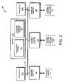
- FIG. 2is a schematic block diagram of a node that may be advantageously used with the present invention.
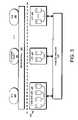
- FIG. 3is a schematic block diagram illustrating the storage subsystem that may be advantageously used with the present invention.
- FIG. 4is a partial schematic block diagram of a storage operating system that may be advantageously used with the present invention.
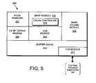
- FIG. 5is a schematic block diagram of a D-blade that may be advantageously used with the present invention.
- FIG. 6is a schematic block diagram illustrating the format of a SpinFS request that may be advantageously used with the present invention
- FIG. 7is a schematic block diagram illustrating the format of a file handle that may be advantageously used with the present invention.
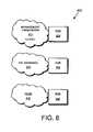
- FIG. 8is a schematic block diagram illustrating a collection of management processes that may be advantageously used with the present invention.
- FIG. 9is a schematic block diagram illustrating a buffer tree in accordance with an embodiment of the present invention.
- FIG. 10is a schematic block diagram illustrating an illustrative inode in accordance with an embodiment of the present invention.
- FIG. 11is a flow chart detailing the steps of a procedure for preloading indirect blocks in accordance with an embodiment of the present invention.
- FIG. 12is a schematic block diagram of an exemplary procedure for preloading indirect blocks in accordance with an alternate embodiment of the present invention.
- FIG. 1is a schematic block diagram of a plurality of nodes 200 interconnected as a cluster 100 and configured to provide storage service relating to the organization of information on storage devices of a storage subsystem.
- the nodes 200comprise various functional components that cooperate to provide a distributed Spin File System (SpinFS) architecture of the cluster 100 .
- SpinFSSpin File System
- each SpinFS node 200is generally organized as a network element (N-blade 110 ) and a disk element (D-blade 500 ).
- the N-blade 110includes a plurality of ports that couple the node 200 to clients 180 over a computer network 140
- each D-blade 500includes a plurality of ports that connect the node to a storage subsystem 300 .
- the nodes 200are interconnected by a cluster switching fabric 150 which, in the illustrative embodiment, may be embodied as a Gigabit Ethernet switch.
- the distributed SpinFS architectureis generally described in U.S. Pat. No. 6,671,773 titled Method and System for Responding to File System Requests, by M. Kazar et al. issued Dec. 30, 2003.
- FIG. 2is a schematic block diagram of a node 200 that is illustratively embodied as a storage system server comprising a plurality of processors 222 , a memory 224 , a network adapter 225 , a cluster access adapter 226 and a storage adapter 228 interconnected by a system bus 223 .
- the cluster access adapter 226comprises a plurality of ports adapted to couple the node 200 to other nodes of the cluster 100 .
- Ethernetis used as the clustering protocol and interconnect media, although it will be apparent to those skilled in the art that other types of protocols and interconnects may be utilized within the cluster architecture described herein.
- Each node 200is illustratively embodied as a dual processor server system executing a storage operating system 400 that provides a file system configured to logically organize the information as a hierarchical structure of named directories and files on storage subsystem 300 .
- the node 200may alternatively comprise a single or more than two processor system.
- one processor 222 aexecutes the functions of the N-blade 110 on the node, while the other processor 222 b executes the functions of the D-blade 500 .
- the memory 224comprises storage locations that are addressable by the processors and adapters for storing software program code and data structures associated with the present invention.
- the processor and adaptersmay, in turn, comprise processing elements and/or logic circuitry configured to execute the software code and manipulate the data structures.
- the storage operating system 400portions of which are typically resident in memory and executed by the processing elements, functionally organizes the node 200 by, inter alia, invoking storage operations in support of the storage service implemented by the node. It will be apparent to those skilled in the art that other processing and memory means, including various computer readable media, may be used for storing and executing program instructions pertaining to the inventive system and method described herein.
- the network adapter 225comprises a plurality of ports adapted to couple the node 200 to one or more clients 180 over point-to-point links, wide area networks, virtual private networks implemented over a public network (Internet) or a shared local area network, hereinafter referred to as an Ethernet computer network 140 . Therefore, the network adapter 225 may comprise a network interface card (NIC) having the mechanical, electrical and signaling circuitry needed to connect the node to the network. For such a network attached storage (NAS) based network environment, the clients are configured to access information stored on the node 200 as files.
- the clients 180communicate with each node over network 140 by exchanging discrete frames or packets of data according to pre-defined protocols, such as the Transmission Control Protocol/Internet Protocol (TCP/IP).
- TCP/IPTransmission Control Protocol/Internet Protocol
- the storage adapter 228cooperates with the storage operating system 400 executing on the node 200 to access information requested by the clients.
- the informationmay be stored on disks or other similar media adapted to store information.
- the storage adaptercomprises a plurality of ports having input/output (I/O) interface circuitry that couples to the disks over an I/O interconnect arrangement, such as a conventional high-performance, Fibre Channel (FC) link topology.
- I/Oinput/output
- FCFibre Channel
- FIG. 3is a schematic block diagram illustrating the storage subsystem 300 that may be advantageously used with the present invention.
- Storage of information on the storage subsystem 300is illustratively implemented as a plurality of storage disks 310 defining an overall logical arrangement of disk space.
- the disksare further organized as one or more groups or sets of Redundant Array of Independent (or Inexpensive) Disks (RAID).
- RAID implementationsenhance the reliability/integrity of data storage through the writing of data “stripes” across a given number of physical disks in the RAID group, and the appropriate storing of redundant information with respect to the striped data.
- the redundant informationenables recovery of data lost when a storage device fails. It will be apparent to those skilled in the art that other redundancy techniques, such as mirroring, may used in accordance with the present invention.
- Each RAID setis illustratively configured by one or more disk (e.g., RAID) controllers 330 .
- the RAID controller 330exports a RAID set as a logical unit number (LUN 320 ) to the D-blade 500 , which writes and reads blocks to and from the LUN 320 .
- LUN 320logical unit number
- One or more LUNsare illustratively organized as a storage pool 350 , wherein each storage pool 350 is “owned” by a D-blade 500 in the cluster 100 .
- Each storage pool 350is further organized as a plurality of virtual file systems (VFSs 380 ), each of which is also owned by the D-blade.
- Each VFS 380may be organized within the storage pool according to a hierarchical policy that, among other things, allows the VFS to be dynamically moved among nodes of the cluster to, for example, control load among individual storage pools.
- a VFS 380is synonymous with a volume and comprises a root directory, as well as a number of subdirectories and files.
- a group of VFSsmay be composed into a larger namespace.
- a root directory(c:) may be contained within a root VFS (“/”), which is the VFS that begins a translation process from a pathname associated with an incoming request to actual data (file) in a file system, such as the SpinFS file system.
- the root VFSmay contain a directory (“system”) or a mount point (“user”).
- a mount pointis a SpinFS object used to “vector off” to another VFS and which contains the name of that vectored VFS.
- the file systemmay comprise one or more VFSs that are “stitched together” by mount point objects.
- the storage operating system 400implements a write-anywhere file system, such as the SpinFS file system, which logically organizes the information as a hierarchical structure of named directories and files on the disks.
- a write-anywhere file systemsuch as the SpinFS file system
- any appropriate storage operating systemincluding a write in-place file system, may be enhanced for use in accordance with the inventive principles described herein.
- Each “on-disk” filemay be implemented as set of disk blocks configured to store information, such as data, whereas the directory may be implemented as a specially formatted file in which names and links to other files and directories are stored.
- the term “storage operating system”generally refers to the computer-executable code operable on a computer that manages data access and may, in the case of a node 200 , implement data access semantics of a general purpose operating system.
- the storage operating systemcan also be implemented as a microkernel, an application program operating over a general-purpose operating system, such as UNIX® or Windows NT®, or as a general-purpose operating system with configurable functionality, which is configured for storage applications as described herein.
- inventive system and method described hereinmay apply to any type of special-purpose (e.g., storage serving appliance) or general-purpose computer, including a standalone computer or portion thereof, embodied as or including a storage system.
- teachings of this inventioncan be adapted to a variety of storage system architectures including, but not limited to, a network-attached storage environment, a storage area network and disk assembly directly-attached to a client or host computer.
- storage systemshould therefore be taken broadly to include such arrangements in addition to any subsystems configured to perform a storage function and associated with other equipment or systems.
- FIG. 4is a partial schematic block diagram of the storage operating system 400 that may be advantageously used with the present invention.
- the storage operating systemcomprises a series of software layers organized to form an integrated network protocol stack 430 that provides a data path for clients to access information stored on the node 200 using file access protocols.
- the protocol stackincludes a media access layer 410 of network drivers (e.g., gigabit Ethernet drivers) that interfaces to network protocol layers, such as the IP layer 412 and its supporting transport mechanisms, the TCP layer 414 and the User Datagram Protocol (UDP) layer 416 .
- a file system protocol layerprovides multi-protocol file access to a file system 450 (the SpinFS file system) and, thus, includes support for the CIFS protocol 220 and the NFS protocol 222 .
- a plurality of management processesexecutes as user mode applications 800 .
- the processors 222share various resources of the node 200 , including the storage operating system 400 .
- the N-blade 110executes the integrated network protocol stack 430 of the operating system 400 to thereby perform protocol termination with respect to a client issuing incoming NFS/CIFS file access request packets over the network 140 .
- the NFS/CIFS layers of the network protocol stackfunction as NFS/CIFS servers 422 , 420 that translate NFS/CIFS requests from a client into SpinFS protocol requests used for communication with the D-blade 500 .
- the SpinFS protocolis a file system protocol that provides operations related to those operations contained within the incoming file access packets. Local communication between an N-blade and D-blade of a node is preferably effected through the use of message passing between the blades, while remote communication between an N-blade and D-blade of different nodes occurs over the cluster switching fabric 150 .
- the NFS and CIFS servers of an N-blade 110convert the incoming file access requests into SpinFS requests that are processed by the D-blades 500 of the cluster 100 .
- Each D-blade 500provides a disk interface function through execution of the SpinFS file system 450 .
- the file systems 450cooperate to provide a single SpinFS file system image across all of the D-blades in the cluster.
- any network port of an N-blade that receives a client requestcan access any file within the single file system image located on any D-blade 500 of the cluster.
- FIG. 5is a schematic block diagram of the D-blade 500 comprising a plurality of functional components including a file system processing module (the inode manager 502 ), a logical-oriented block processing module (the Bmap module 504 ) and a Bmap volume module 506 .
- the inode manager 502is the processing module that implements the SpinFS file system 450
- the Bmap module 504is responsible for all block allocation functions associated with a write anywhere policy of the file system 450 , including reading and writing all data to and from the RAID controller 330 of storage subsystem 300 .
- the Bmap volume module 506implements all VFS operations in the cluster 100 , including creating and deleting a VFS, mounting and unmounting a VFS in the cluster, moving a VFS, as well as cloning (snapshotting) and mirroring a VFS.
- the D-bladealso includes a high availability storage pool (HA SP) voting module 508 , a log module 510 , a buffer cache 512 and a fibre channel device driver (FCD) module.
- HA SPhigh availability storage pool
- FCDfibre channel device driver
- FIG. 6is a schematic block diagram illustrating the format of a SpinFS request 600 that illustratively includes a media access layer 602 , an IP layer 604 , a UDP layer 606 , an RF layer 608 and a SpinFS protocol layer 610 .
- the SpinFS protocol 610is a file system protocol that provides operations, related to those operations contained within incoming file access packets, to access files stored on the cluster 100 .
- the SpinFS protocol 610is datagram based and, as such, involves transmission of packets or “envelopes” in a reliable manner from a source (e.g., an N-blade) to a destination (e.g., a D-blade).
- the RF layer 608implements a reliable transport protocol that is adapted to process such envelopes in accordance with a connectionless protocol, such as UDP 606 .
- FIG. 7is a schematic block diagram illustrating the format of a file handle 700 including a VFS ID field 702 , an inode number field 704 and a unique-ifier field 706 .
- the VFS ID field 702is contains an identifier of a VFS that is unique (global) within the entire cluster 100 .
- the inode number field 704contains an inode number of a particular inode within an inode file of a particular VFS.
- the unique-ifier field 706contains a monotonically increasing number that uniquely identifies the file handle 700 , particularly in the case where an inode number has been deleted, reused and reassigned to a new file. The unique-ifier distinguishes that reused inode number in a particular VFS from a potentially previous use of those fields.
- FIG. 8is a schematic block diagram illustrating a collection of management processes that execute as user mode applications 800 on the storage operating system 400 to provide management of configuration information (i.e. management data) for the nodes of the cluster.
- the management processesinclude a management framework process 810 , a high availability manager (HA Mgr) process 820 , a VFS location database (VLDB) process 830 and a replicated database (RDB) process 850 .
- the management framework 810provides a user interface via a command line interface (CLI) and/or graphical user interface (GUI).
- CLIcommand line interface
- GUIgraphical user interface
- the management frameworkis illustratively based on a conventional common interface model (CIM) object manager that provides the entity to which users/system administrators interact with a node 200 in order to manage the cluster 100 .
- CIMcommon interface model
- the HA Mgr 820manages all network addresses (IP addresses) of all nodes 200 on a cluster-wide basis. For example, assume a network adapter 225 having two IP addresses (IP 1 and IP 2 ) on a node fails. The HA Mgr 820 relocates those two IP addresses onto another N-blade of a node within the cluster to thereby enable clients to transparently survive the failure of an adapter (interface) on an N-blade 110 . The relocation (repositioning) of IP addresses within the cluster is dependent upon configuration information provided by a system administrator. The HA Mgr 820 is also responsible for functions such as monitoring an uninterrupted power supply (UPS) and notifying the D-blade to write its data to persistent storage when a power supply issue arises within the cluster.
- UPSuninterrupted power supply
- the VLDB 830is a database process that tracks the locations of various storage components (e.g., a VFS) within the cluster 100 to thereby facilitate routing of requests throughout the cluster.
- the N-blade 110 of each nodehas a look up table that maps the VFS ID 702 of a file handle 700 to a D-blade 500 that “owns” (is running) the VFS 380 within the cluster.
- the VLDBprovides the contents of the look up table by, among other things, keeping track of the locations of the VFSs 380 within the cluster.
- the VLDBhas a remote procedure call (RPC) interface, e.g., a Sun RPC interface, which allows the N-blade 110 to query the VLDB 830 .
- RPCremote procedure call
- the N-bladeWhen encountering a VFS ID 702 that is not stored in its mapping table, the N-blade sends an RPC to the VLDB process. In response, the VLDB 830 returns to the N-blade the appropriate mapping information, including an identifier of the D-blade that owns the VFS. The N-blade caches the information in its look up table and uses the D-blade ID to forward the incoming request to the appropriate VFS 380 .
- the RDBcomprises a library that provides a persistent object store (storing of objects) for the management data processed by the management processes.
- the RDB 850replicates and synchronizes the management data object store access across all nodes 200 of the cluster 100 to thereby ensure that the RDB database is identical (has an identical image) on all of the nodes 200 .
- the HA Mgr 820uses the RDB library 850 to monitor the status of the IP addresses within the cluster.
- each node 200records the status/state of its interfaces and IP addresses (those IP addresses it “owns”) into the RDB database.
- requestsare issued by clients 180 and received at the network protocol stack 430 of an N-blade 110 within a node 200 of the cluster 100 .
- the requestis parsed through the network protocol stack to the appropriate NFS/CIFS server, where the specified VFS 380 (and file), along with the appropriate D-blade 500 that “owns” that VFS, are determined.
- the appropriate serverthen translates the incoming request into a SpinFS request 600 that is routed to the D-blade 500 .
- the D-bladereceives the SpinFS request and apportions it into a part that is relevant to the requested file (for use by the inode manager 502 ), as well as a part that is relevant to specific access (read/write) allocation with respect to blocks on the disk (for use by the Bmap module 504 ). All functions and interactions between the N-blade 110 and D-blade 500 are coordinated on a cluster-wide basis through the collection of management processes and the RDB library user mode applications 800 .
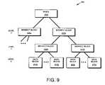
- FIG. 9is a schematic block diagram of an exemplary buffer tree 900 of a file.
- an inode 1000At the top of the buffer tree of the file is an inode 1000 , which may be stored within an inode file of the file system.
- Inode filesare further described in U.S. patent application Ser. No. 10/777,979 filed on Feb. 12, 2004 now issued as U.S. Pat. No. 7,313,720 issued Dec. 25, 2007, entitled TECHNIQUE FOR INCREASING THE NUMBER OF PERSISTENT CONSISTENCY POINT IMAGES IN A FILE SYSTEM, by Emily Eng, et al.
- the inodecontains a series of pointers to high-level indirect blocks 905 a,b , which in turn contain pointers to additional low-level indirect blocks 910 a,b .
- At the base of the fileare individual data blocks 915 a - d .
- Each data blockillustratively represents a 4 KB on-disk block.
- the data blocksare labeled as direct or level 0 (L0) blocks 915
- indirect blocks that point directly to data blocksare labeled as level 1 (L1) blocks 910 .
- L2 blocks 905are level 2 (L2) blocks 905 .
- Buffer tree 900is illustratively representative of a file having an inode and two levels of indirect blocks, L1 and L2, pointing to direct blocks; however, it should be noted that the principle of the present invention applies to files having any number of indirect blocks. Two levels of indirect blocks are shown for illustrative purposes only and should not be taken as limiting the present invention.
- FIG. 10is an exemplary inode 1000 data structure according to an embodiment of the present invention.
- the inode 1000includes a meta-data section 1005 and a data section 1060 that illustratively starts a series of disk block pointers 1035 , 1040 , 1045 , 1050 .
- a fileis represented in the write-anywhere file system by an inode data structure adapted for storage on the disks 310 .
- the information stored in the metadata section 1005describes the file and, as such, includes the type (e.g., regular, directory, virtual disk) 1010 of file, the size 1015 of the file, time stamps (e.g., access and/or modification) 1020 for the file and ownership, i.e., user identifier (UID 1025 ) and group ID (GID 1030 ), of the file.
- typee.g., regular, directory, virtual disk
- time stampse.g., access and/or modification
- UID 1025user identifier
- GID 1030group ID
- the disk block pointers 1035 , 1040 , 1045 , 1050contain pointers to direct or indirect blocks of a buffer tree for the file represented by the inode.
- pointer 1035points to a direct block
- pointer 1040points to a L1 indirect block
- pointer 1045points to a L2 indirect block
- pointer 1050points to a L6 indirect block.
- each of the pointers 1035 , 1040 , 1045 , 1050may point to any level of indirect or direct block, depending on the size of the file associated with the inode.
- the present inventionis directed to a technique that accelerates file deletion of a file (preferably a large file) by preloading indirect blocks of the file stored by a storage system, such as node 200 having an inode-based file system 450 .
- the techniqueaccelerates traversal of buffer tree 900 of the file during file deletion by preloading a predefined number (N) of low-level (L1) indirect blocks referenced by a high-level (L2) indirect block into buffer cache 512 before those L1 blocks are needed for processing.
- Nis preferably chosen to ensure that all preloaded indirect blocks may be stored in the buffer cache without overflowing the cache.
- 128 L1 blocksare loaded into the cache at a time. Once loaded, the L1 indirect blocks are temporarily stored (cached) until requested for processing. Preloading of the indirect blocks thereby obviates the need to perform a plurality of single block access requests to disk.
- a Bmap module of the storage systemprocesses the indirect blocks during file deletion by, inter alia, freeing data blocks referenced by pointers of the L1 blocks of the file.
- the Bmap moduleaccesses the L1 blocks by reading pointers contained in L2 blocks of the file.
- the Bmap modulereads a first portion of the block to access a first L1.
- the Bmap modulethen sends a request to a cache controller to return the first L1 indirect block from the buffer cache. If the L1 block is not currently residing in the cache, the Bmap module (or cache controller) issues a read request to a disk controller to retrieve the next N L1 indirect blocks of the file.
- the cache controllerforwards the preloaded indirect block from the cache module.
- pre-loadingsignificantly improves file deletion performance as it obviates the need to perform multiple single indirect block data access requests.
- FIG. 11is a flowchart detailing the steps of a procedure 1100 for preloading indirect blocks of a large file in accordance with an embodiment of the present invention.
- the procedure 1100is invoked during a file deletion operation.
- the procedurebegins in step 1105 and continues to step 1110 where the Bmap module sends a request to a cache controller 516 for a L1 indirect block to process.
- the Bmap 504may request a L1 indirect block while it is currently processing a L2 indirect block that references a plurality of L1 blocks. Alternately, if the file size is of an appropriate size, the inode may directly reference a plurality of L1 blocks.
- the cache controller 516alerts the Bmap module that the block is not resident in the buffer cache 512 .
- the Bmap module(or cache controller) issues a read request to the disk controller 330 for the next N L1 indirect blocks from disk.
- N128, however the value of N may vary depending on a variety of factors including the size of the buffer cache and the size of indirect blocks in the file system. The value of N is illustratively set so that the N indirect blocks do not cause the buffer cache to overflow, thereby requiring additional read operations. In alternate embodiments, the value of N may vary dynamically based on the amount of available buffer cache memory, i.e., N is proportional to the amount of free buffer cache.
- the RAID controllerreturns the requested blocks and forwards them to the cache controller, which loads the next N L1 indirect blocks into the buffer cache. Then, in step 1125 , the Bmap module receives the first requested L1 indirect block from the buffer cache. It should be noted that the N indirect blocks may not arrive simultaneously into the buffer cache; however, the RAID controller 310 of the storage subsystem 300 may be processing the disk access request for the N indirect blocks while other modules of the D-blade are processing the received indirect blocks, thereby creating, in effect, a parallel processing system that improves system performance and reduces the time required for large file deletion.
- the Bmap modulethen processes the received L1 indirect block (step 1130 ) using conventional file deletion techniques, i.e., clearing bits corresponding to data blocks referenced by pointers in the L1 block.
- the bitsare stored in an allocation bitmap structure 229 maintained by the Bmap module 504 .
- the Bmap 504“frees” a block by clearing a corresponding bit in the bitmap 229 .
- step 1145the Bmap module requests the next L1 indirect block.
- the procedurereturns to step 1120 and where the next N L1 indirect blocks are loaded into the buffer cache. This will occur when, e.g., the Bmap module has processed all N of the previously loaded blocks, which may result in a slight performance delay at the end of each N blocks.
- the N indirect blockswere loaded in a single operation instead of in N disk operations, a significant improvement in system performance is achieved.
- FIG. 12is a flowchart of a procedure 1200 for preloading indirect blocks in accordance with an alternate embodiment of the present invention that eliminates the performance delay at the end of every N blocks.
- the procedurebegins in step 1205 and continues to step 1210 where the Bmap module requests a L1 indirect block from the buffer cache and the cache controller alerts the Bmap module that the block is not loaded into the buffer cache (step 1215 ).
- the Bmap module(or cache controller) issues a read request (step 1220 ) to the RAID controller 330 for the next N L1 indirect blocks. This read request results in the next N indirect blocks being loaded into the buffer cache.
- the Bmap modulereceives the first L1 indirect block in step 1225 and processes the L1 indirect block in step 1230 .
- the proceduredetermines if there are additional blocks to process in step 1235 . If there are no further L1 indirect blocks to process, the procedure branches to step 1240 and is complete. Otherwise, the procedure continues to step 1235 where the procedure determines if it has processed at least X of the N L1 indirect blocks. The value of X is set to an appropriate level so that a request for an additional N blocks will not overflow the buffer cache.
- the procedurebranches to step 1255 where the Bmap module (or cache controller) issues a read request for an additional N L1 indirect blocks.
- the Bmap modulerequests an additional Y L1 indirect blocks, wherein Y does not equal N. This may occur when, for example, requesting an additional N blocks would cause the buffer cache to overflow, thereby resulting in additional read requests.
- the selection of N, X, and Yis configurable by an administrator to optimize the performance of the file system depending on the specific implementation.
- this alternate embodiment“smooths” the flow of indirect blocks into the buffer cache compared to the illustrative embodiment, which may have an interrupt after each N blocks.
- the values of N, X and Ymay be chosen to achieve the best performance depending on the specifics of the file system implementing the teachings of the present invention.
- a Bmap module of the storage systemprocesses the indirect blocks during file deletion by, inter alia, freeing data blocks references by pointers of the L1 blocks of the file.
- the Bmap moduleaccesses the L1 blocks by reading pointers contained in L2 blocks of the file.
- the Bmap modulereads a first portion of the block to access a first L1.
- the Bmap modulethen sends a requests to a cache controller to return the first L1 indirect block from the buffer cache.
- the Bmap module(or cache controller) issues a read request to a disk controller to retrieve the next N L1 indirect blocks of the file. Thereafter, while the Bmap module processes the first L1 indirect block, the next L1 indirect blocks to be processed are loaded or are being loaded into the buffer cache. When the Bmap module completes processing of the first L1 indirect block and requests the next L1 indirect block, the cache controller forwards the preloaded indirect block from the cache module.
- preloadingsignificantly improves file deletion performance as it obviates the need to perform multiple single indirect block data access requests.
- a read requestis issued for an additional N indirect blocks from disk, thereby eliminating the slight delay that occurs between processing the Nth and N+1 st indirect block in the illustrative embodiment.
Landscapes
- Engineering & Computer Science (AREA)
- Theoretical Computer Science (AREA)
- Human Computer Interaction (AREA)
- Physics & Mathematics (AREA)
- General Engineering & Computer Science (AREA)
- General Physics & Mathematics (AREA)
- Information Retrieval, Db Structures And Fs Structures Therefor (AREA)
Abstract
Description
The present invention is directed to deleting files in a file system and, in particular to accelerating file deletion by preloading indirect blocks.
A storage system is a computer that provides storage service relating to the organization of information on storage devices, such as disks. The storage system may be deployed within a network attached storage (NAS) environment and, as such, may be embodied as a file server. The file server or filer includes a storage operating system that implements a file system to logically organize the information as a hierarchical structure of directories and files on the disks. Each “on-disk” file may be implemented as a set of data structures, e.g., disk blocks, configured to store information. A directory, on the other hand, may be implemented as a specially formatted file in which information about other files and directories are stored.
A filer may be further configured to operate according to a client/server model of information delivery to thereby allow many clients to access files stored on a server, e.g., the filer. In this model, the client may comprise an application, such as a database application, executing on a computer that “connects” to the filer over a computer network, such as a point-to-point link, shared local area network (LAN), wide area network (WAN), or virtual private network (VPN) implemented over a public network such as the Internet. Each client may request the services of the file system on the filer by issuing file system protocol messages (in the form of packets) to the filer over the network.
A common type of file system is a “write in-place” file system, an example of which is the conventional Berkeley fast file system. In a write in-place file system, the locations of the data structures, such as inodes and data blocks, on disk are typically fixed. An inode is a data structure used to store information, such as meta-data, about a file, whereas the data blocks are structures used to store the actual data for the file. The information contained in an inode may include, e.g., ownership of the file, access permission for the file, size of the file, file type and references to locations on disk of the data blocks for the file. The references to the locations of the file data are provided by pointers, which may further reference indirect blocks that, in turn, reference the data blocks, depending upon the quantity of data in the file. Changes to the inodes and data blocks are made “in-place” in accordance with the write in-place file system. If an update to a file extends the quantity of data for the file, an additional data block is allocated and the appropriate inode is updated to reference that data block.
Another type of file system is a write-anywhere file system that does not over-write data on disks. If a data block on disk is retrieved (read) from disk into memory and “dirtied” with new data, the data is stored (written) to a new location on disk to thereby optimize write performance. A write-anywhere file system may initially assume an optimal layout such that the data is substantially contiguously arranged on disks. The optimal disk layout results in efficient access operations, particularly for sequential read operations, directed to the disks. A particular example of a write-anywhere file system that is configured to operate on a filer is the SpinFS file system available from Network Appliance, Inc. of Sunnyvale, Calif. The SpinFS file system utilizes a write anywhere technique for user and directory data but writes metadata in place. The SpinFS file system is implemented within a storage operating system having a protocol stack and associated disk storage.
When accessing a block of a file in response to servicing a client request, the file system retrieves the requested block from disk and stores it in a buffer cache of the memory as part of a buffer tree of the file. The buffer tree is an internal representation of blocks of a file stored in the buffer cache and maintained by the file system. Broadly stated, the buffer tree has an inode at the root (top-level) of the file. For a large file, the inode contains pointers that may reference high-level (e.g. level 2, L2) indirect blocks, which blocks may also contain pointers that reference low-level (e.g.,level 1, L1) indirect blocks. The L1 indirect blocks, in turn, contain pointers that reference the actual data blocks of the file.
Disk storage is typically implemented as one or more storage “volumes” that comprise physical storage disks, defining an overall logical arrangement of storage space. Currently available filer implementations can serve a large number of discrete volumes (150 or more, for example). Each volume is associated with its own file system and, for purposes hereof, volume and file system shall generally be used synonymously. The disks within a volume are typically organized as one or more groups of Redundant Array of Independent (or Inexpensive) Disks (RAID). RAID implementations enhance the reliability/integrity of data storage through the redundant writing of data “stripes” across a given number of physical disks in the RAID group, and the appropriate caching of parity information with respect to the striped data. As described herein, a volume typically comprises at least one data disk and one associated parity disk (or possibly data/parity partitions in a single disk) arranged according to aRAID 4, or equivalent high-reliability, implementation.
The write anywhere file system typically includes a storage allocator that performs write allocation of blocks in a volume in response to an event in the file system (e.g., dirtying of the blocks in a file). The storage allocator uses block allocation structures, such as an allocation bitmap, to select free blocks within its storage space to which to write the dirty blocks. Each bit in the allocation bitmap structure corresponds to a block in the volume; freeing a block involves clearing of the corresponding bit in the allocation bitmap, whereas selecting (allocating) a block involves setting the corresponding bit. The allocated blocks are generally in the same positions along the disks for each RAID group (i.e., within a stripe) so as to optimize use of the parity disks.
A noted advantage of write anywhere file systems is that write operations directed to many files can be collected and later committed to disk in a batch operation, thereby increasing system performance by writing large blocks of contiguous data to disk at once. The optimized write performance of the write anywhere file system may result in the dirtied data of the files being stored in new locations separate and apart from the originally stored data of the files. Accordingly, the blocks of a file may be scattered among the disks of the volume. This results in a noted disadvantage of write anywhere file systems, namely, the latencies involved with (slowness of) file deletion, especially of a large (i.e., multi-megabyte) file.
During a file deletion operation, the buffer tree of the file is loaded from disk. Given the scattered nature of the file, loading of indirect blocks of the file typically occurs serially (i.e., one indirect block at a time) from disk, which results in numerous single block disk access requests. If the indirect block is a low-level (L1) indirect block, i.e., one that directly points to (references) data, the storage allocator serially (one at a time) clears the bit in the allocation bitmap corresponding to the data block referenced by each pointer in the block, and then clears the allocation bit corresponding to the L1 block. If the indirect block is a high level (L2) indirect block) then each L1 indirect block referenced by a pointer in the L2 block must be loaded (serially) for processing as described above. As a result, many single block disk access requests are generated during file deletion, which adversely affects (slows) system performance.
One technique for improving file deletion performance is to immediately remove the file from its directory, thereby making it “invisible” (inaccessible) to a user of the file system. Individual blocks of the file may then be asynchronously deleted at a later time using, e.g., a “lazy-write” technique of processing indirect blocks (as described above) when there is free processing time or available disk access bandwidth. However, this technique does not eliminate the substantial time required to individually load each indirect block for processing. That is, the storage allocator must still work its way down (traverse) the buffer tree of the file, retrieving a first high level (L2) block, reading a first pointer of the L2 block and retrieving its referenced low level (L1) block, and serially freeing each data block referenced by the pointers of the L1 block. The storage allocator then reads a second pointer of the L2 block, retrieves its referenced L1 block and processes that block as described above. This process continues in a manner that spreads the numerous single block access requests over a longer period of time, which generates an increased load over a longer period of time.
The disadvantages of the prior art are overcome by a novel technique that accelerates file deletion by preloading indirect blocks of a large file served by a storage system. In particular, the technique accelerates traversal of a buffer tree of the file during a file deletion operation by preloading a predefined number (N) of low level (L1) indirect blocks referenced by a high level (L2) indirect block into a buffer cache of the storage system before those L1 blocks are needed for processing. The value of N is chosen to ensure that all preloaded indirect blocks may be stored in the buffer without overflowing the cache, thereby enabling rapid processing without the need for single block access requests to disk.
In the illustrative embodiment, a Bmap module of the storage system, such as a file server, processes the indirect blocks during file deletion by, inter alia, freeing data is blocks referenced by pointers of the L1 blocks of the file. The Bmap module accesses the L1 blocks by reading pointers contained in L2 blocks of the file. When processing an L2 block, the Bmap module reads a first portion of the block to access a first L1. The Bmap module then sends a requests to a cache controller to return the first L1 indirect block from the buffer cache. If the L1 block is not currently residing in the cache, the Bmap module (or cache controller) issues a read request to a disk controller to retrieve the next N L1 indirect blocks of the file. Thereafter, while the Bmap module processes the first L1 indirect block, the next L1 indirect blocks to be processed are loaded or are being loaded into the buffer cache. When the Bmap module completes processing of the first L1 indirect block and requests the next L1 indirect block, the cache controller forwards the preloaded indirect block from the cache module.
Advantageously, such preloading significantly improves file deletion performance as it obviates the need to perform multiple single indirect block data access requests. However, a situation may arise where there is a slight delay at the completion of processing of the N preloaded indirect blocks when the Bmap module requests the N+1st L1 indirect block, which is not preloaded into the buffer cache. As a result, a new request for the next N L1 indirect blocks must be issued to the disk controller. In an embodiment, a request for an additional N blocks may be sent to the disk controller after a predefined number of the first N blocks have been processed. This “overlapping” enhancement to the novel technique removes the slight delay that occurs at the end of each N block quantum.
The above and further advantages of invention may be better understood by referring to the following description in conjunction with the accompanying drawings in which like reference numerals indicate identical or functionally similar elements:
A. Cluster Environment
B. Storage Systems
Eachnode 200 is illustratively embodied as a dual processor server system executing astorage operating system 400 that provides a file system configured to logically organize the information as a hierarchical structure of named directories and files onstorage subsystem 300. However, it will be apparent to those of ordinary skill in the art that thenode 200 may alternatively comprise a single or more than two processor system. Illustratively, oneprocessor 222aexecutes the functions of the N-blade 110 on the node, while theother processor 222bexecutes the functions of the D-blade 500.
In the illustrative embodiment, thememory 224 comprises storage locations that are addressable by the processors and adapters for storing software program code and data structures associated with the present invention. The processor and adapters may, in turn, comprise processing elements and/or logic circuitry configured to execute the software code and manipulate the data structures. Thestorage operating system 400, portions of which are typically resident in memory and executed by the processing elements, functionally organizes thenode 200 by, inter alia, invoking storage operations in support of the storage service implemented by the node. It will be apparent to those skilled in the art that other processing and memory means, including various computer readable media, may be used for storing and executing program instructions pertaining to the inventive system and method described herein.
Thenetwork adapter 225 comprises a plurality of ports adapted to couple thenode 200 to one ormore clients 180 over point-to-point links, wide area networks, virtual private networks implemented over a public network (Internet) or a shared local area network, hereinafter referred to as anEthernet computer network 140. Therefore, thenetwork adapter 225 may comprise a network interface card (NIC) having the mechanical, electrical and signaling circuitry needed to connect the node to the network. For such a network attached storage (NAS) based network environment, the clients are configured to access information stored on thenode 200 as files. Theclients 180 communicate with each node overnetwork 140 by exchanging discrete frames or packets of data according to pre-defined protocols, such as the Transmission Control Protocol/Internet Protocol (TCP/IP).
Thestorage adapter 228 cooperates with thestorage operating system 400 executing on thenode 200 to access information requested by the clients. The information may be stored on disks or other similar media adapted to store information. The storage adapter comprises a plurality of ports having input/output (I/O) interface circuitry that couples to the disks over an I/O interconnect arrangement, such as a conventional high-performance, Fibre Channel (FC) link topology. The information is retrieved by the storage adapter and, if necessary, processed by the processor222 (or theadapter 228 itself) prior to being forwarded over thesystem bus 223 to thenetwork adapter 225 where the information is formatted into packets or messages and returned to the clients.
Each RAID set is illustratively configured by one or more disk (e.g., RAID)controllers 330. TheRAID controller 330 exports a RAID set as a logical unit number (LUN320) to the D-blade 500, which writes and reads blocks to and from theLUN 320. One or more LUNs are illustratively organized as astorage pool 350, wherein eachstorage pool 350 is “owned” by a D-blade 500 in thecluster 100. Eachstorage pool 350 is further organized as a plurality of virtual file systems (VFSs380), each of which is also owned by the D-blade. EachVFS 380 may be organized within the storage pool according to a hierarchical policy that, among other things, allows the VFS to be dynamically moved among nodes of the cluster to, for example, control load among individual storage pools.
In the illustrative embodiment, aVFS 380 is synonymous with a volume and comprises a root directory, as well as a number of subdirectories and files. A group of VFSs may be composed into a larger namespace. For example, a root directory (c:) may be contained within a root VFS (“/”), which is the VFS that begins a translation process from a pathname associated with an incoming request to actual data (file) in a file system, such as the SpinFS file system. The root VFS may contain a directory (“system”) or a mount point (“user”). A mount point is a SpinFS object used to “vector off” to another VFS and which contains the name of that vectored VFS. The file system may comprise one or more VFSs that are “stitched together” by mount point objects.
C. Storage Operating System
To facilitate access to thedisks 310 and information stored thereon, thestorage operating system 400 implements a write-anywhere file system, such as the SpinFS file system, which logically organizes the information as a hierarchical structure of named directories and files on the disks. However, it is expressly contemplated that any appropriate storage operating system, including a write in-place file system, may be enhanced for use in accordance with the inventive principles described herein. Each “on-disk” file may be implemented as set of disk blocks configured to store information, such as data, whereas the directory may be implemented as a specially formatted file in which names and links to other files and directories are stored.
As used herein, the term “storage operating system” generally refers to the computer-executable code operable on a computer that manages data access and may, in the case of anode 200, implement data access semantics of a general purpose operating system. The storage operating system can also be implemented as a microkernel, an application program operating over a general-purpose operating system, such as UNIX® or Windows NT®, or as a general-purpose operating system with configurable functionality, which is configured for storage applications as described herein.
In addition, it will be understood to those skilled in the art that the inventive system and method described herein may apply to any type of special-purpose (e.g., storage serving appliance) or general-purpose computer, including a standalone computer or portion thereof, embodied as or including a storage system. Moreover, the teachings of this invention can be adapted to a variety of storage system architectures including, but not limited to, a network-attached storage environment, a storage area network and disk assembly directly-attached to a client or host computer. The term “storage system” should therefore be taken broadly to include such arrangements in addition to any subsystems configured to perform a storage function and associated with other equipment or systems.
In the illustrative embodiment, the processors222 share various resources of thenode 200, including thestorage operating system 400. To that end, the N-blade 110 executes the integratednetwork protocol stack 430 of theoperating system 400 to thereby perform protocol termination with respect to a client issuing incoming NFS/CIFS file access request packets over thenetwork 140. The NFS/CIFS layers of the network protocol stack function as NFS/CIFS servers blade 500. The SpinFS protocol is a file system protocol that provides operations related to those operations contained within the incoming file access packets. Local communication between an N-blade and D-blade of a node is preferably effected through the use of message passing between the blades, while remote communication between an N-blade and D-blade of different nodes occurs over the cluster switching fabric150.
D. D-Blade
Specifically, the NFS and CIFS servers of an N-blade 110 convert the incoming file access requests into SpinFS requests that are processed by the D-blades 500 of thecluster 100. Each D-blade 500 provides a disk interface function through execution of theSpinFS file system 450. In theillustrative cluster 100, thefile systems 450 cooperate to provide a single SpinFS file system image across all of the D-blades in the cluster. Thus, any network port of an N-blade that receives a client request can access any file within the single file system image located on any D-blade 500 of the cluster.FIG. 5 is a schematic block diagram of the D-blade 500 comprising a plurality of functional components including a file system processing module (the inode manager502), a logical-oriented block processing module (the Bmap module504) and aBmap volume module 506. Theinode manager 502 is the processing module that implements theSpinFS file system 450, whereas theBmap module 504 is responsible for all block allocation functions associated with a write anywhere policy of thefile system 450, including reading and writing all data to and from theRAID controller 330 ofstorage subsystem 300. TheBmap volume module 506, on the other hand, implements all VFS operations in thecluster 100, including creating and deleting a VFS, mounting and unmounting a VFS in the cluster, moving a VFS, as well as cloning (snapshotting) and mirroring a VFS. The D-blade also includes a high availability storage pool (HA SP)voting module 508, alog module 510, abuffer cache 512 and a fibre channel device driver (FCD) module.
E. SpinFS
The NFS and CIFS servers on the N-blade 110 translate respective NFS and CIFS requests into SpinFS primitive operations contained within SpinFS packets (requests).FIG. 6 is a schematic block diagram illustrating the format of aSpinFS request 600 that illustratively includes amedia access layer 602, anIP layer 604, aUDP layer 606, anRF layer 608 and aSpinFS protocol layer 610. As noted, theSpinFS protocol 610 is a file system protocol that provides operations, related to those operations contained within incoming file access packets, to access files stored on thecluster 100. Illustratively, theSpinFS protocol 610 is datagram based and, as such, involves transmission of packets or “envelopes” in a reliable manner from a source (e.g., an N-blade) to a destination (e.g., a D-blade). TheRF layer 608 implements a reliable transport protocol that is adapted to process such envelopes in accordance with a connectionless protocol, such asUDP 606.
Files are accessed in theSpinFS file system 450 using a file handle.FIG. 7 is a schematic block diagram illustrating the format of afile handle 700 including aVFS ID field 702, aninode number field 704 and a unique-ifier field 706. TheVFS ID field 702 is contains an identifier of a VFS that is unique (global) within theentire cluster 100. Theinode number field 704 contains an inode number of a particular inode within an inode file of a particular VFS. The unique-ifier field 706 contains a monotonically increasing number that uniquely identifies thefile handle 700, particularly in the case where an inode number has been deleted, reused and reassigned to a new file. The unique-ifier distinguishes that reused inode number in a particular VFS from a potentially previous use of those fields.
TheHA Mgr 820 manages all network addresses (IP addresses) of allnodes 200 on a cluster-wide basis. For example, assume anetwork adapter 225 having two IP addresses (IP1 and IP2) on a node fails. TheHA Mgr 820 relocates those two IP addresses onto another N-blade of a node within the cluster to thereby enable clients to transparently survive the failure of an adapter (interface) on an N-blade 110. The relocation (repositioning) of IP addresses within the cluster is dependent upon configuration information provided by a system administrator. TheHA Mgr 820 is also responsible for functions such as monitoring an uninterrupted power supply (UPS) and notifying the D-blade to write its data to persistent storage when a power supply issue arises within the cluster.
TheVLDB 830 is a database process that tracks the locations of various storage components (e.g., a VFS) within thecluster 100 to thereby facilitate routing of requests throughout the cluster. In the illustrative embodiment, the N-blade 110 of each node has a look up table that maps theVFS ID 702 of afile handle 700 to a D-blade 500 that “owns” (is running) theVFS 380 within the cluster. The VLDB provides the contents of the look up table by, among other things, keeping track of the locations of theVFSs 380 within the cluster. The VLDB has a remote procedure call (RPC) interface, e.g., a Sun RPC interface, which allows the N-blade 110 to query theVLDB 830. When encountering aVFS ID 702 that is not stored in its mapping table, the N-blade sends an RPC to the VLDB process. In response, theVLDB 830 returns to the N-blade the appropriate mapping information, including an identifier of the D-blade that owns the VFS. The N-blade caches the information in its look up table and uses the D-blade ID to forward the incoming request to theappropriate VFS 380.
All of these management processes have interfaces to (are closely coupled to) a replicated database (RDB)850. The RDB comprises a library that provides a persistent object store (storing of objects) for the management data processed by the management processes. Notably, theRDB 850 replicates and synchronizes the management data object store access across allnodes 200 of thecluster 100 to thereby ensure that the RDB database is identical (has an identical image) on all of thenodes 200. For example, theHA Mgr 820 uses theRDB library 850 to monitor the status of the IP addresses within the cluster. At system startup, eachnode 200 records the status/state of its interfaces and IP addresses (those IP addresses it “owns”) into the RDB database.
Operationally, requests are issued byclients 180 and received at thenetwork protocol stack 430 of an N-blade 110 within anode 200 of thecluster 100. The request is parsed through the network protocol stack to the appropriate NFS/CIFS server, where the specified VFS380 (and file), along with the appropriate D-blade 500 that “owns” that VFS, are determined. The appropriate server then translates the incoming request into aSpinFS request 600 that is routed to the D-blade 500. The D-blade receives the SpinFS request and apportions it into a part that is relevant to the requested file (for use by the inode manager502), as well as a part that is relevant to specific access (read/write) allocation with respect to blocks on the disk (for use by the Bmap module504). All functions and interactions between the N-blade 110 and D-blade 500 are coordinated on a cluster-wide basis through the collection of management processes and the RDB libraryuser mode applications 800.
Thedisk block pointers pointer 1035 points to a direct block,pointer 1040 points to a L1 indirect block,pointer 1045 points to a L2 indirect block andpointer 1050 points to a L6 indirect block. However, in alternate embodiments, each of thepointers
F. Accelerating File Deletion by Preloading Indirect Blocks
The present invention is directed to a technique that accelerates file deletion of a file (preferably a large file) by preloading indirect blocks of the file stored by a storage system, such asnode 200 having an inode-basedfile system 450. In particular, the technique accelerates traversal ofbuffer tree 900 of the file during file deletion by preloading a predefined number (N) of low-level (L1) indirect blocks referenced by a high-level (L2) indirect block intobuffer cache 512 before those L1 blocks are needed for processing. The value of N is preferably chosen to ensure that all preloaded indirect blocks may be stored in the buffer cache without overflowing the cache. Illustratively, 128 L1 blocks are loaded into the cache at a time. Once loaded, the L1 indirect blocks are temporarily stored (cached) until requested for processing. Preloading of the indirect blocks thereby obviates the need to perform a plurality of single block access requests to disk.
In the illustrative embodiment, a Bmap module of the storage system, such as a file server, processes the indirect blocks during file deletion by, inter alia, freeing data blocks referenced by pointers of the L1 blocks of the file. The Bmap module accesses the L1 blocks by reading pointers contained in L2 blocks of the file. When processing an L2 block, the Bmap module reads a first portion of the block to access a first L1. The Bmap module then sends a request to a cache controller to return the first L1 indirect block from the buffer cache. If the L1 block is not currently residing in the cache, the Bmap module (or cache controller) issues a read request to a disk controller to retrieve the next N L1 indirect blocks of the file. Thereafter, while the Bmap module processes the first L1 indirect block, the next L1 indirect blocks to be processed are loaded or are being loaded into the buffer cache. When the Bmap module completes processing of the first L1 indirect block and requests the next L1 indirect block, the cache controller forwards the preloaded indirect block from the cache module. Advantageously, such pre-loading significantly improves file deletion performance as it obviates the need to perform multiple single indirect block data access requests.
The RAID controller returns the requested blocks and forwards them to the cache controller, which loads the next N L1 indirect blocks into the buffer cache. Then, instep 1125, the Bmap module receives the first requested L1 indirect block from the buffer cache. It should be noted that the N indirect blocks may not arrive simultaneously into the buffer cache; however, theRAID controller 310 of thestorage subsystem 300 may be processing the disk access request for the N indirect blocks while other modules of the D-blade are processing the received indirect blocks, thereby creating, in effect, a parallel processing system that improves system performance and reduces the time required for large file deletion.
The Bmap module then processes the received L1 indirect block (step1130) using conventional file deletion techniques, i.e., clearing bits corresponding to data blocks referenced by pointers in the L1 block. In the illustrative embodiment, the bits are stored in anallocation bitmap structure 229 maintained by theBmap module 504. Using thebitmap 229, theBmap 504 “frees” a block by clearing a corresponding bit in thebitmap 229. Once the received L1 indirect block has been processed, the file system determines, instep 1135, if there are additional blocks to be processed. If there are no further L1 indirect blocks to be processed, then the procedure branches to step1140 and completes. Otherwise, the procedure continues to step1145 where the Bmap module requests the next L1 indirect block. A determination is made instep 1150 if the requested block has been loaded in the buffer cache. If the requested L1 indirect block is located in the buffer cache, then the procedure branches to step1155 where the requested L1 indirect block is loaded from the buffer cache to the Bmap module before returning tostep 1130.
However, if the requested L1 indirect block is not in the buffer cache, then the procedure returns to step1120 and where the next N L1 indirect blocks are loaded into the buffer cache. This will occur when, e.g., the Bmap module has processed all N of the previously loaded blocks, which may result in a slight performance delay at the end of each N blocks. However, as the N indirect blocks were loaded in a single operation instead of in N disk operations, a significant improvement in system performance is achieved.
If X indirect blocks have been processed, the procedure branches to step1255 where the Bmap module (or cache controller) issues a read request for an additional N L1 indirect blocks. In yet another alternate embodiment, the Bmap module requests an additional Y L1 indirect blocks, wherein Y does not equal N. This may occur when, for example, requesting an additional N blocks would cause the buffer cache to overflow, thereby resulting in additional read requests. The selection of N, X, and Y is configurable by an administrator to optimize the performance of the file system depending on the specific implementation. Once the additional L1 indirect blocks have been requested the procedure continues to step1250 where the Bmap module request the next L1 indirect block before returning tostep 1230.
Advantageously, this alternate embodiment “smooths” the flow of indirect blocks into the buffer cache compared to the illustrative embodiment, which may have an interrupt after each N blocks. As noted, the values of N, X and Y may be chosen to achieve the best performance depending on the specifics of the file system implementing the teachings of the present invention.
To again summarize, the present invention provides a technique for accelerating file deletion by preloading L1 indirect blocks. In the illustrative embodiment, a Bmap module of the storage system, such as a file server, processes the indirect blocks during file deletion by, inter alia, freeing data blocks references by pointers of the L1 blocks of the file. The Bmap module accesses the L1 blocks by reading pointers contained in L2 blocks of the file. When processing an L2 block, the Bmap module reads a first portion of the block to access a first L1. The Bmap module then sends a requests to a cache controller to return the first L1 indirect block from the buffer cache. If the L1 block is not currently residing in the cache, the Bmap module (or cache controller) issues a read request to a disk controller to retrieve the next N L1 indirect blocks of the file. Thereafter, while the Bmap module processes the first L1 indirect block, the next L1 indirect blocks to be processed are loaded or are being loaded into the buffer cache. When the Bmap module completes processing of the first L1 indirect block and requests the next L1 indirect block, the cache controller forwards the preloaded indirect block from the cache module. Advantageously, such preloading significantly improves file deletion performance as it obviates the need to perform multiple single indirect block data access requests. In an alternate embodiment, once X of the N indirect blocks have been processed, a read request is issued for an additional N indirect blocks from disk, thereby eliminating the slight delay that occurs between processing the Nth and N+1stindirect block in the illustrative embodiment.
The foregoing description has been directed to particular embodiments of this invention. It will be apparent, however, that other variations and modifications may be made to the described embodiments, with the attainment of some or all of their advantages. Additionally, the procedures or processes may be implemented in hardware, software, embodied as a computer-readable medium having program instructions, firmware, or a combination thereof. Therefore, it is the object of the appended claims to cover all such variations and modifications as come within the true spirit and scope of the invention.
Claims (10)
1. A method for accelerating file deletion of a file served by a storage system, comprising:
invoking a file deletion operation to delete a selected file;
reading, in response to the file deletion operation, a high-level indirect block of a buffer tree of the selected file to locate one or more low-level indirect blocks referenced by the high-level indirect block;
issuing read requests, in response to locating the one or more low-level indirect blocks, for the one or more low-level indirect blocks;
processing a first low-level indirect block of the one or more low-level indirect blocks in parallel with executing the read requests;
preloading into a buffer cache memory a number of one or more low-level indirect blocks that were read while the first low-level block is being processed, wherein the number, of the one or more low-level indirect blocks to be preloaded, chosen to ensure that the one or more low-level indirect blocks do not overflow the buffer cache memory; and
freeing data blocks referenced by pointers of the first low-level indirect block in response to the file deletion operation to delete the data blocks.
2. The method ofclaim 1 , further comprising:
processing, by the storage system, the low-level indirect blocks referenced by the high-level indirect block.
3. The method ofclaim 1 , further comprising:
preloading the one or more low-level indirect blocks referenced by the high-level indirect block into the buffer cache of the storage system before the one or more low-level indirect blocks are needed for processing.
4. The method ofclaim 1 , further comprising:
processing the first low-level indirect block by clearing a set of pointers in the first low level indirect block.
5. The method ofclaim 1 , further comprising:
representing each low-level indirect block as a 4 KB block.
6. A storage system, comprising:
an operating system having a file deletion operation;
in response to the file deletion operation, reading a high-level indirect block of a buffer tree of a selected file to locate one or more low-level indirect blocks referenced by the high-level indirect blocks;
read requests to be issued in response to locating the one or more low-level indirect blocks;
a first low-level indirect block of the one or more low-level indirect blocks to be processed in parallel to executing the read requests;
a number of one or more low-level indirect blocks that were read to be preloaded into a buffer cache memory while the first low level indirect block is being processed, wherein the number, of the one or more low-level indirect blocks to be preloaded, chosen to ensure that the one or more low-level indirect blocks do not overflow the buffer cache memory; and
data blocks referenced by pointers of the first low-level indirect block are freed in response to the file deletion operation to delete the data blocks.
7. The system ofclaim 6 , further comprising:
the one or more low-level indirect blocks referenced by the high-level indirect block are processed by the storage system.
8. The system ofclaim 6 , further comprising:
the first low-level indirect block is processed by clearing a set of pointers in the first low level indirect block.
9. The system ofclaim 6 , further comprising:
each low-level indirect block represented as a 4 KB block.
10. A computer readable media, comprising:
said computer readable media containing instructions for execution on a processor for a method of accelerated file deletion of a file served by a storage system, the method having;
invoking a file deletion operation to delete a selected file;
reading, in response to the file deletion operation, a high-level indirect block of a buffer tree of the selected file to locate one or more low-level indirect blocks referenced by the high-level indirect block;
issuing read requests, in response to locating the one or more low-level indirect blocks, for the one or more low-level indirect blocks;
processing a first low-level indirect block of the one or more low-level indirect blocks in parallel to executing-the read requests;
preloading into a buffer cache memory a number of one or more low-level indirect blocks that were read while the first low-level indirect block is being processed, wherein the number, of the one or more low-level indirect blocks to be preloaded, chosen to ensure that the one or more low-level indirect blocks do not overflow the buffer cache memory; and
freeing data blocks referenced by pointers of the first low-level indirect block in response to the file deletion operation to delete the data blocks.
Priority Applications (1)
| Application Number | Priority Date | Filing Date | Title |
|---|---|---|---|
| US10/858,492US7509329B1 (en) | 2004-06-01 | 2004-06-01 | Technique for accelerating file deletion by preloading indirect blocks |
Applications Claiming Priority (1)
| Application Number | Priority Date | Filing Date | Title |
|---|---|---|---|
| US10/858,492US7509329B1 (en) | 2004-06-01 | 2004-06-01 | Technique for accelerating file deletion by preloading indirect blocks |
Publications (1)
| Publication Number | Publication Date |
|---|---|
| US7509329B1true US7509329B1 (en) | 2009-03-24 |
Family
ID=40457253
Family Applications (1)
| Application Number | Title | Priority Date | Filing Date |
|---|---|---|---|
| US10/858,492Expired - LifetimeUS7509329B1 (en) | 2004-06-01 | 2004-06-01 | Technique for accelerating file deletion by preloading indirect blocks |
Country Status (1)
| Country | Link |
|---|---|
| US (1) | US7509329B1 (en) |
Cited By (8)
| Publication number | Priority date | Publication date | Assignee | Title |
|---|---|---|---|---|
| US20050226603A1 (en)* | 2001-08-08 | 2005-10-13 | Mitsuhiro Hirabayashi | Recording apparatus, recording method, and recording medium |
| US20100011037A1 (en)* | 2008-07-11 | 2010-01-14 | Arriad, Inc. | Media aware distributed data layout |
| US20100250834A1 (en)* | 2009-03-31 | 2010-09-30 | Trika Sanjeev N | Method and system to perform caching based on file-level heuristics |
| US20170031828A1 (en)* | 2015-07-31 | 2017-02-02 | Oracle International Corporation | Systems and methods for coordinating interdependent asynchronous reads |
| US20170228170A1 (en)* | 2011-12-30 | 2017-08-10 | Intel Corporation | Write Mechanism for Storage Class Memory |
| US10248655B2 (en) | 2008-07-11 | 2019-04-02 | Avere Systems, Inc. | File storage system, cache appliance, and method |
| US10268717B2 (en)* | 2013-07-02 | 2019-04-23 | Red Hat, Inc. | System and method for reading file blocks |
| US20200012735A1 (en)* | 2018-07-06 | 2020-01-09 | Vmware, Inc. | Reducing write amplification in buffer trees |
Citations (30)
| Publication number | Priority date | Publication date | Assignee | Title |
|---|---|---|---|---|
| US4156907A (en) | 1977-03-02 | 1979-05-29 | Burroughs Corporation | Data communications subsystem |
| US4399503A (en) | 1978-06-30 | 1983-08-16 | Bunker Ramo Corporation | Dynamic disk buffer control unit |
| US4598357A (en) | 1980-11-14 | 1986-07-01 | Sperry Corporation | Cache/disk subsystem with file number for recovery of cached data |
| US4688221A (en) | 1983-12-28 | 1987-08-18 | Hitachi, Ltd. | Error recovery method and apparatus |
| US4698808A (en) | 1984-12-14 | 1987-10-06 | International Business Machines Corporation | Method for detecting intermittent error in volatile memory |
| US4761785A (en) | 1986-06-12 | 1988-08-02 | International Business Machines Corporation | Parity spreading to enhance storage access |
| US4805090A (en) | 1985-09-27 | 1989-02-14 | Unisys Corporation | Peripheral-controller for multiple disk drive modules having different protocols and operating conditions |
| US4837675A (en) | 1981-10-05 | 1989-06-06 | Digital Equipment Corporation | Secondary storage facility empolying serial communications between drive and controller |
| US4864497A (en) | 1988-04-13 | 1989-09-05 | Digital Equipment Corporation | Method of integrating software application programs using an attributive data model database |
| WO1989010594A1 (en) | 1988-04-22 | 1989-11-02 | Amdahl Corporation | A file system for a plurality of storage classes |
| US4896259A (en) | 1984-09-07 | 1990-01-23 | International Business Machines Corporation | Apparatus for storing modifying data prior to selectively storing data to be modified into a register |
| US4899342A (en) | 1988-02-01 | 1990-02-06 | Thinking Machines Corporation | Method and apparatus for operating multi-unit array of memories |
| US4989206A (en) | 1988-06-28 | 1991-01-29 | Storage Technology Corporation | Disk drive memory |
| US5124987A (en) | 1990-04-16 | 1992-06-23 | Storage Technology Corporation | Logical track write scheduling system for a parallel disk drive array data storage subsystem |
| USRE34100E (en) | 1987-01-12 | 1992-10-13 | Seagate Technology, Inc. | Data error correction system |
| US5155835A (en) | 1990-11-19 | 1992-10-13 | Storage Technology Corporation | Multilevel, hierarchical, dynamically mapped data storage subsystem |
| US5239644A (en)* | 1988-03-28 | 1993-08-24 | Hitachi, Ltd. | Data preloading method and system for using a buffer |
| US5426747A (en) | 1991-03-22 | 1995-06-20 | Object Design, Inc. | Method and apparatus for virtual memory mapping and transaction management in an object-oriented database system |
| US5581724A (en) | 1992-10-19 | 1996-12-03 | Storage Technology Corporation | Dynamically mapped data storage subsystem having multiple open destage cylinders and method of managing that subsystem |
| US5996047A (en)* | 1996-07-01 | 1999-11-30 | Sun Microsystems, Inc. | Method and apparatus for caching file control information corresponding to a second file block in a first file block |
| US6003115A (en)* | 1997-07-29 | 1999-12-14 | Quarterdeck Corporation | Method and apparatus for predictive loading of a cache |
| US6098096A (en)* | 1996-12-09 | 2000-08-01 | Sun Microsystems, Inc. | Method and apparatus for dynamic cache preloading across a network |
| US6289356B1 (en)* | 1993-06-03 | 2001-09-11 | Network Appliance, Inc. | Write anywhere file-system layout |
| US20010021959A1 (en)* | 2000-02-18 | 2001-09-13 | Holmberg Per Anders | Static cache |
| US6397311B1 (en)* | 1990-01-19 | 2002-05-28 | Texas Instruments Incorporated | System and method for defragmenting a file system |
| US20020116593A1 (en) | 2000-12-07 | 2002-08-22 | Spinnaker Networks, Inc. | Method and system for responding to file system requests |
| US6463509B1 (en)* | 1999-01-26 | 2002-10-08 | Motive Power, Inc. | Preloading data in a cache memory according to user-specified preload criteria |
| US20030182317A1 (en)* | 2002-03-22 | 2003-09-25 | Kahn Andy C. | File folding technique |
| US6636879B1 (en) | 2000-08-18 | 2003-10-21 | Network Appliance, Inc. | Space allocation in a write anywhere file system |
| US20060129766A1 (en)* | 2002-08-14 | 2006-06-15 | Cassia Simon H | Method and apparatus for preloading caches |
- 2004
- 2004-06-01USUS10/858,492patent/US7509329B1/ennot_activeExpired - Lifetime
Patent Citations (31)
| Publication number | Priority date | Publication date | Assignee | Title |
|---|---|---|---|---|
| US4156907A (en) | 1977-03-02 | 1979-05-29 | Burroughs Corporation | Data communications subsystem |
| US4399503A (en) | 1978-06-30 | 1983-08-16 | Bunker Ramo Corporation | Dynamic disk buffer control unit |
| US4598357A (en) | 1980-11-14 | 1986-07-01 | Sperry Corporation | Cache/disk subsystem with file number for recovery of cached data |
| US4837675A (en) | 1981-10-05 | 1989-06-06 | Digital Equipment Corporation | Secondary storage facility empolying serial communications between drive and controller |
| US4688221A (en) | 1983-12-28 | 1987-08-18 | Hitachi, Ltd. | Error recovery method and apparatus |
| US4896259A (en) | 1984-09-07 | 1990-01-23 | International Business Machines Corporation | Apparatus for storing modifying data prior to selectively storing data to be modified into a register |
| US4698808A (en) | 1984-12-14 | 1987-10-06 | International Business Machines Corporation | Method for detecting intermittent error in volatile memory |
| US4805090A (en) | 1985-09-27 | 1989-02-14 | Unisys Corporation | Peripheral-controller for multiple disk drive modules having different protocols and operating conditions |
| US4761785A (en) | 1986-06-12 | 1988-08-02 | International Business Machines Corporation | Parity spreading to enhance storage access |
| US4761785B1 (en) | 1986-06-12 | 1996-03-12 | Ibm | Parity spreading to enhance storage access |
| USRE34100E (en) | 1987-01-12 | 1992-10-13 | Seagate Technology, Inc. | Data error correction system |
| US4899342A (en) | 1988-02-01 | 1990-02-06 | Thinking Machines Corporation | Method and apparatus for operating multi-unit array of memories |
| US5239644A (en)* | 1988-03-28 | 1993-08-24 | Hitachi, Ltd. | Data preloading method and system for using a buffer |
| US4864497A (en) | 1988-04-13 | 1989-09-05 | Digital Equipment Corporation | Method of integrating software application programs using an attributive data model database |
| WO1989010594A1 (en) | 1988-04-22 | 1989-11-02 | Amdahl Corporation | A file system for a plurality of storage classes |
| US4989206A (en) | 1988-06-28 | 1991-01-29 | Storage Technology Corporation | Disk drive memory |
| US6397311B1 (en)* | 1990-01-19 | 2002-05-28 | Texas Instruments Incorporated | System and method for defragmenting a file system |
| US5124987A (en) | 1990-04-16 | 1992-06-23 | Storage Technology Corporation | Logical track write scheduling system for a parallel disk drive array data storage subsystem |
| US5155835A (en) | 1990-11-19 | 1992-10-13 | Storage Technology Corporation | Multilevel, hierarchical, dynamically mapped data storage subsystem |
| US5426747A (en) | 1991-03-22 | 1995-06-20 | Object Design, Inc. | Method and apparatus for virtual memory mapping and transaction management in an object-oriented database system |
| US5581724A (en) | 1992-10-19 | 1996-12-03 | Storage Technology Corporation | Dynamically mapped data storage subsystem having multiple open destage cylinders and method of managing that subsystem |
| US6289356B1 (en)* | 1993-06-03 | 2001-09-11 | Network Appliance, Inc. | Write anywhere file-system layout |
| US5996047A (en)* | 1996-07-01 | 1999-11-30 | Sun Microsystems, Inc. | Method and apparatus for caching file control information corresponding to a second file block in a first file block |
| US6098096A (en)* | 1996-12-09 | 2000-08-01 | Sun Microsystems, Inc. | Method and apparatus for dynamic cache preloading across a network |
| US6003115A (en)* | 1997-07-29 | 1999-12-14 | Quarterdeck Corporation | Method and apparatus for predictive loading of a cache |
| US6463509B1 (en)* | 1999-01-26 | 2002-10-08 | Motive Power, Inc. | Preloading data in a cache memory according to user-specified preload criteria |
| US20010021959A1 (en)* | 2000-02-18 | 2001-09-13 | Holmberg Per Anders | Static cache |
| US6636879B1 (en) | 2000-08-18 | 2003-10-21 | Network Appliance, Inc. | Space allocation in a write anywhere file system |
| US20020116593A1 (en) | 2000-12-07 | 2002-08-22 | Spinnaker Networks, Inc. | Method and system for responding to file system requests |
| US20030182317A1 (en)* | 2002-03-22 | 2003-09-25 | Kahn Andy C. | File folding technique |
| US20060129766A1 (en)* | 2002-08-14 | 2006-06-15 | Cassia Simon H | Method and apparatus for preloading caches |
Non-Patent Citations (56)
| Title |
|---|
| Administration Guide found at http://www.openafs.org/pages/doc/AdminGuide/auagd010.htm, visited on Mar. 2, 2005. |
| Basilico, et al., Error Correction System Using "Shadow Memory," IBM Technical Disclosure Bulletin, May 1984, pp. 5792-5793. |
| Bitton, Dina, Disk Shadowing, Proceedings of the 14th VLDB Conference, LA, CA (1988). |
| Blasgen, M.W. et al., System R:An architectural Overview,Reprinted from IBM Systems Journal vol. 20, No. 1, 1981 (C) 1981, 1999. |
| Borenstein, Nathaniel S., CMU's Andrew project a retrospective, Communications of ACM, 39(12), Dec. 1996. |
| Brown, Mark R. et al., The Alpine file system, ACM Transactions on Computing Systems, 3(4):261-293, Nov. 1985. |
| Chen, Peter M., et al., An Evaluation of Redundant Arrays of Disks Using an Amdahl 5890 Performance Evaluation, pp. 74-85, 1990. |
| Chutani, Sailesh, et al., The Episode file system, In Proceedings of the USENIX Winter 1992. |
| Clark, B.E., et al., Application System/400 Performance Characteristics, IBM Systems Journal, 28(3): 407-423, 1989. |
| Data Sheet for the Check Point Software Technologies product Flood-Gate-1 (1997). |
| Dibble, Peter C., et al., Beyond Striping: The Bridge Multiprocessor File System, Computer Science Department, University of Rochester, Aug. 11, 1989. |
| Douglis, Fred, et al., A comparison of two distributed systems: Amoeba and Sprite-Computing Systems, 4(4), Fall 1991, pp. 353-385 ? |
| Gait, Jason, Phoenix: A Safe In-Memory File System. Communications of the ACM, 33(1):81-86, Jan. 1990. |
| Hartman, John H. et al., Performance Measurements of a Multiprocessor Sprite Kernel, Proceedings of the USENIX Conference, 1990. |
| Hitz, Dave et al., File System Design for an NFS File Server Appliance, Technical Report 3002, Rev. C395, presented Jan. 19, 1994. |
| Howard, John H, et al., Scale and Performance in a Distributed File System, Carnegie Mellon University, CMU-ITC-87-068, Aug. 5, 1987. |
| Howard, John H., An Overview of the Andrew File System, Carnegie Mellon University, CMU-ITC-88-062. |
| Howard, John, H. et al., Scale and performance in a distributed file system, ACM Trans. Computer. System., 6(1), Feb. 1988 pp. 51-81. |
| Isomaki, Markus, Diferentiated Service for the Internet, Department of Technical Physics and Mathematics, May 9, 1998. |
| Kazar, Michael L., et al., Decorum File System Architectural Overview, USENIX Summer Conference, Anaheim, California, 1990. |
| Lomet, David., et al., The performance of a multiversion access method, ACM SIGMOD International Conference on Management of Data, 19:353-363. |
| Lorie, RA, Shadow Page Mechanism, IBM Technical Disclosure Bulletin, Jun. 1986, pp. 340-342. |
| Lorie, Raymond, A, Physical integrity in a large segmented database, ACM Trans. Database Systems, (2)1: 91-104, Mar. 1977. |
| McKusick, Marshall Kirk, et al., A Fast File System for UNIX, Computer Science Division, Department of Electrical Engineering and Computer Sciences, Univ. of CA, Berkley, Feb. 18, 1994. |
| Miller, Ethan, L., et al., RAMA:A File System for Massively Parallel Computers, 12th IEEE Symposium on Mass Storage Systems, Monterey, CA, Apr. 1993, pp. 163-168. |
| Moons, Herman et al., Location-Independent Object Invocation in Open Distributed Systems, Autumn 1991 EurOpen Technical Conference and Exhibition, pp. 287-300 (Sep. 16-20, 1991). |
| Morris, James H., et al, Andrew: A Distributed Personal Computing Environment, Comm. of the ACM, vol. 29, Mar. 1986, pp. 184-201. |
| Mullender, Sape J., et al., A distributed file service based on optimistic concurrency control, ACM Symposium on Operating System Principles (Orcas Island, Washington). Published as Operating Systems Review, 19(5):51-62, Dec. 1985. |
| Muller, Keith, et al., A High Performance Multi-Structured File System Design, In Proceedings of the 13th ACM Symposium on Operating Systems Principles, Oct. 1991, pp. 56-67. |
| Ousterhout, John et al., Beating the I/O Bottleneck: A Case for Log-Structured File Systems, Technical Report, Computer Science Division, Electrical Engineering and Computer Sciences, University of California at Berkeley, Oct. 30, 1988. |
| Ousterhout, John K. et al., The Sprite Network Operating System, Computer Science Division, Department of Electrical Engineering and Computer Sciences, Univ. of CA, Berkley, Nov. 19, 1987. |
| Ousterhout, John, A Brief Retrospective On The Sprite Network Operating System, found at http://www.cs.berkeley.edu/projects/sprite/retrospective,html, visited on Mar. 11, 2005. |
| Ousterhout, John, Why Aren't Operating Systems Getting Faster as Fast as Hardware?, Digital WRL Technical Note TN-11, Oct. 1989. |
| Patterson, D., et al., A Case for Redundant Arrays of Inexpensive Disks (RAID), SIGMOD International Conference on Management of Data, Chicago, IL, USA, Jun. 1-3, 1988, SIGMOD Record (17)3:109-16 (Sep. 1988). |
| Patterson, D., et al., A Case for Redundant Arrays of Inexpensive Disks (RAID), Technical Report, CSD-87-391, Computer Science Division, Electrical Engineering and Computer Sciences, University of California at Berkeley (1987). |
| Peterson, Zachary Nathaniel Joseph, Data Placement for Copy-on-Write Using Virtual Contiguity, University of CA, Santa Cruz, Master of Science in Computer Science Thesis, Sep. 2002. |
| Quinlan, Sean, A Cached WORM File System, Software-Practice and Experience, 21(12):1289-1299 (1991). |
| Redundant Array of Independent Disks, from Wikipedia, the free encyclopedia, found at http://en.wikipedia.org/wiki/RAID, visited on Mar. 9, 2005. |
| Rosenberg, J., et al., Stability in a Persistent Store Based on a Large Virtual Memory, In Security and Persistence, Rosenber, J. & Keedy, J.L. (ed), Springer-Verlag (1990) pp. 229-245. |
| Rosenblum, Mendel, et al, The Design and Implementation of a Log-Structured File System Jul. 24, 1991, pp. 1-15. |
| Rosenblum, Mendel, et al., The Design and Implementation of a Log-Structured File System, , In Proceedings of ACM Transactions on Computer Systems, (10)1:26-52, Feb. 1992. |
| Rosenblum, Mendel, et al., The LFS Storage Manager, Computer Science Division, Electrical Engin. And Computer Sciences, Univ. of CA, presented at Summer '90 USENIX Technical Conference, Anaheim, CA Jun. 1990. |
| Sandberg, Russel et al., Design and Implementation of the Sun Network Filesystem. In Proc. Summer 1985 USENIX Conf., pp. 119-130, Portland OR (USA), Jun. 1985. |
| Santry, Douglas S., et al., Deciding When to Forget in the Elephant File System, Operating Systems Review, 34(5), (Dec. 1999) pp. 110-123. |
| Satyanarayanan, M., et al, Coda: A highly available file system for a distributed workstation environment Carnegie Mellon University, CMU-ITC. |
| Satyanarayanan, M., et al, Coda: A highly available file system for a distributed workstation environment. IEEE Transactions on Computers, 39(4):447-459, 1990. |
| Satyanarayanan, M., et al., The ITC Distributed File System: Principles and Design, In Proceedings of the 10th ACM Symposium on Operating Systems Principles, (19)5:56-67, Dec. 1985. |
| Satyanarayanan, Mahadev, Scalable, Secure, and Highly Available Distributed File Access, Computer May 1990: 9-21. |
| Satyanarayanan,.M.. A survey of distributed file-systems. Annual Review of Computing Science, 4(73-104), 1989. |
| Sidebotham, Bob, Volumes: The Andrew File System Data Structuring Primitive, EEUG Conference Proceedings, Manchester, UK, Autumn 1986. |
| The IBM System/38, Chapter 8, pp. 137-15. |
| U.S. Appl. No. 10/777,979, filed Feb. 12, 2004, Eng et al. |
| User Guide found at http://www.openafs.org/pages/doc/UserGuide/auusg004.htm, visited on Mar. 2, 2005. |
| Welch, Brent B., et al., Pseudo Devices: User-Level Extensions to the Sprite File System, Computer Science Division, Department of Electrical Engineering and Computer Sciences, Univ. of CA, Berkley, Apr. 1988. |
| Welch, Brent B., et al., Pseudo-File-Systems, Computer Science Division, Department of Electrical Engineering and Computer Sciences, Univ. of CA, Berkley, Oct. 1989. |
| Wittle, Mark, et al, LADDIS: The next generation in NFS file server benchmarking, USENIX Association Conference Proceedings, Apr. 1993. |
Cited By (30)
| Publication number | Priority date | Publication date | Assignee | Title |
|---|---|---|---|---|
| US20050226603A1 (en)* | 2001-08-08 | 2005-10-13 | Mitsuhiro Hirabayashi | Recording apparatus, recording method, and recording medium |
| US7609296B2 (en)* | 2001-08-08 | 2009-10-27 | Sony Corporation | Recording apparatus, recording method, and recording medium using an index file |
| US20170293442A1 (en)* | 2008-07-11 | 2017-10-12 | Avere Systems, Inc. | Media Aware Distributed Data Layout |
| US20100011037A1 (en)* | 2008-07-11 | 2010-01-14 | Arriad, Inc. | Media aware distributed data layout |
| US10769108B2 (en) | 2008-07-11 | 2020-09-08 | Microsoft Technology Licensing, Llc | File storage system, cache appliance, and method |
| US10338853B2 (en)* | 2008-07-11 | 2019-07-02 | Avere Systems, Inc. | Media aware distributed data layout |
| US20160335015A1 (en)* | 2008-07-11 | 2016-11-17 | Avere Systems, Inc. | Media Aware Distributed Data Layout |
| US20160313948A1 (en)* | 2008-07-11 | 2016-10-27 | Avere Systems, Inc. | Media Aware Distributed Data Layout |
| US8214404B2 (en)* | 2008-07-11 | 2012-07-03 | Avere Systems, Inc. | Media aware distributed data layout |
| US8412742B2 (en)* | 2008-07-11 | 2013-04-02 | Avere Systems, Inc. | Media aware distributed data layout |
| US8655931B2 (en)* | 2008-07-11 | 2014-02-18 | Avere Systems, Inc. | Media aware distributed data layout |
| US20140115015A1 (en)* | 2008-07-11 | 2014-04-24 | Avere Systems, Inc. | Media Aware Distributed Data Layout |
| US20140156928A1 (en)* | 2008-07-11 | 2014-06-05 | Avere Systems, Inc. | Media Aware Distributed Data Layout |
| US9389806B2 (en)* | 2008-07-11 | 2016-07-12 | Avere Systems, Inc. | Media aware distributed data layout |
| US10248655B2 (en) | 2008-07-11 | 2019-04-02 | Avere Systems, Inc. | File storage system, cache appliance, and method |
| US20170308331A1 (en)* | 2008-07-11 | 2017-10-26 | Avere Systems, Inc. | Media Aware Distributed Data Layout |
| US20110282922A1 (en)* | 2008-07-11 | 2011-11-17 | Kazar Michael L | Media aware distributed data layout |
| US9405487B2 (en)* | 2008-07-11 | 2016-08-02 | Avere Systems, Inc. | Media aware distributed data layout |
| US9696944B2 (en)* | 2008-07-11 | 2017-07-04 | Avere Systems, Inc. | Media aware distributed data layout |
| US9710195B2 (en)* | 2008-07-11 | 2017-07-18 | Avere Systems, Inc. | Media aware distributed data layout |
| US20100250834A1 (en)* | 2009-03-31 | 2010-09-30 | Trika Sanjeev N | Method and system to perform caching based on file-level heuristics |
| US8171219B2 (en) | 2009-03-31 | 2012-05-01 | Intel Corporation | Method and system to perform caching based on file-level heuristics |
| GB2469373B (en)* | 2009-03-31 | 2011-10-19 | Intel Corp | Method and system to perform caching based on file-level heuristics |
| GB2469373A (en)* | 2009-03-31 | 2010-10-13 | Intel Corp | Using file level heuristics to manage a storage device cache |
| US20170228170A1 (en)* | 2011-12-30 | 2017-08-10 | Intel Corporation | Write Mechanism for Storage Class Memory |
| US10268717B2 (en)* | 2013-07-02 | 2019-04-23 | Red Hat, Inc. | System and method for reading file blocks |
| US20170031828A1 (en)* | 2015-07-31 | 2017-02-02 | Oracle International Corporation | Systems and methods for coordinating interdependent asynchronous reads |
| US10241920B2 (en)* | 2015-07-31 | 2019-03-26 | Oracle International Corporation | Systems and methods for coordinating interdependent asynchronous reads |
| US20200012735A1 (en)* | 2018-07-06 | 2020-01-09 | Vmware, Inc. | Reducing write amplification in buffer trees |
| US10997144B2 (en)* | 2018-07-06 | 2021-05-04 | Vmware, Inc. | Reducing write amplification in buffer trees |
Similar Documents
| Publication | Publication Date | Title |
|---|---|---|
| US8578090B1 (en) | System and method for restriping data across a plurality of volumes | |
| US8886778B2 (en) | System and method for proxying network management protocol commands to enable cluster wide management of data backups | |
| US8489811B1 (en) | System and method for addressing data containers using data set identifiers | |
| US8209289B1 (en) | Technique for accelerating the creation of a point in time representation of a virtual file system | |
| US7698289B2 (en) | Storage system architecture for striping data container content across volumes of a cluster | |
| US7739250B1 (en) | System and method for managing file data during consistency points | |
| US7676628B1 (en) | Methods, systems, and computer program products for providing access to shared storage by computing grids and clusters with large numbers of nodes | |
| US8301673B2 (en) | System and method for performing distributed consistency verification of a clustered file system | |
| EP1875384B1 (en) | System and method for multi-tiered meta-data caching and distribution in a clustered computer environment | |
| US7366837B2 (en) | Data placement technique for striping data containers across volumes of a storage system cluster | |
| US8224777B2 (en) | System and method for generating consistent images of a set of data objects | |
| US7197490B1 (en) | System and method for lazy-copy sub-volume load balancing in a network attached storage pool | |
| US8117388B2 (en) | Data distribution through capacity leveling in a striped file system | |
| US7707165B1 (en) | System and method for managing data versions in a file system | |
| US8566845B2 (en) | System and method for optimizing multi-pathing support in a distributed storage system environment | |
| US8041888B2 (en) | System and method for LUN cloning | |
| US9165003B1 (en) | Technique for permitting multiple virtual file systems having the same identifier to be served by a single storage system | |
| US7647451B1 (en) | Data placement technique for striping data containers across volumes of a storage system cluster | |
| US7743210B1 (en) | System and method for implementing atomic cross-stripe write operations in a striped volume set | |
| US20190258604A1 (en) | System and method for implementing a quota system in a distributed file system | |
| US7962689B1 (en) | System and method for performing transactional processing in a striped volume set | |
| US7506111B1 (en) | System and method for determining a number of overwitten blocks between data containers | |
| US7509329B1 (en) | Technique for accelerating file deletion by preloading indirect blocks | |
| US7783611B1 (en) | System and method for managing file metadata during consistency points | |
| US10521159B2 (en) | Non-disruptive automatic application regrouping |
Legal Events
| Date | Code | Title | Description |
|---|---|---|---|
| AS | Assignment | Owner name:NETWORK APPLIANCE, INC., CALIFORNIA Free format text:ASSIGNMENT OF ASSIGNORS INTEREST;ASSIGNORS:SRIVAS, MANDAYAM C.;LEVERETT, BRUCE W.;REEL/FRAME:015737/0040;SIGNING DATES FROM 20040811 TO 20040817 | |
| STCF | Information on status: patent grant | Free format text:PATENTED CASE | |
| CC | Certificate of correction | ||
| FPAY | Fee payment | Year of fee payment:4 | |
| AS | Assignment | Owner name:NETAPP, INC., CALIFORNIA Free format text:CHANGE OF NAME;ASSIGNOR:NETWORK APPLIANCE, INC.;REEL/FRAME:036610/0642 Effective date:20080310 | |
| FPAY | Fee payment | Year of fee payment:8 | |
| MAFP | Maintenance fee payment | Free format text:PAYMENT OF MAINTENANCE FEE, 12TH YEAR, LARGE ENTITY (ORIGINAL EVENT CODE: M1553); ENTITY STATUS OF PATENT OWNER: LARGE ENTITY Year of fee payment:12 | |
| AS | Assignment | Owner name:NETAPP, INC., CALIFORNIA Free format text:CHANGE OF NAME;ASSIGNOR:NETWORK APPLIANCE, INC.;REEL/FRAME:067983/0108 Effective date:20080317 |