US7508813B2 - Local area network contention avoidance - Google Patents
Local area network contention avoidanceDownload PDFInfo
- Publication number
- US7508813B2 US7508813B2US10/722,676US72267603AUS7508813B2US 7508813 B2US7508813 B2US 7508813B2US 72267603 AUS72267603 AUS 72267603AUS 7508813 B2US7508813 B2US 7508813B2
- Authority
- US
- United States
- Prior art keywords
- packet
- switching device
- transmission
- transmitting
- packets
- Prior art date
- Legal status (The legal status is an assumption and is not a legal conclusion. Google has not performed a legal analysis and makes no representation as to the accuracy of the status listed.)
- Expired - Lifetime
Links
Images


Classifications
- H—ELECTRICITY
- H04—ELECTRIC COMMUNICATION TECHNIQUE
- H04L—TRANSMISSION OF DIGITAL INFORMATION, e.g. TELEGRAPHIC COMMUNICATION
- H04L12/00—Data switching networks
- H04L12/28—Data switching networks characterised by path configuration, e.g. LAN [Local Area Networks] or WAN [Wide Area Networks]
- H04L12/46—Interconnection of networks
- H04L12/4604—LAN interconnection over a backbone network, e.g. Internet, Frame Relay
- H04L12/462—LAN interconnection over a bridge based backbone
- H04L12/4625—Single bridge functionality, e.g. connection of two networks over a single bridge
- H—ELECTRICITY
- H04—ELECTRIC COMMUNICATION TECHNIQUE
- H04L—TRANSMISSION OF DIGITAL INFORMATION, e.g. TELEGRAPHIC COMMUNICATION
- H04L47/00—Traffic control in data switching networks
- H04L47/10—Flow control; Congestion control
- H—ELECTRICITY
- H04—ELECTRIC COMMUNICATION TECHNIQUE
- H04L—TRANSMISSION OF DIGITAL INFORMATION, e.g. TELEGRAPHIC COMMUNICATION
- H04L47/00—Traffic control in data switching networks
- H04L47/10—Flow control; Congestion control
- H04L47/12—Avoiding congestion; Recovering from congestion
- H04L47/125—Avoiding congestion; Recovering from congestion by balancing the load, e.g. traffic engineering
Definitions
- the present inventionrelates generally to a system for reducing packet congestion for multiple devices that need to communicate over a network, such as the Internet.
- a networksuch as the Internet.
- the subject matter of this applicationis related to my previously-filed U.S. application Ser. No. 10/697,103, now U.S. Pat. No. 7,339,923, entitled “Endpoint Packet Scheduling System,” filed on Oct. 31, 2003.
- Ethernet and packet-switched Internet Protocol (IP) networksare systems for transmitting data between different points. These systems are known as “contention-based” systems. That is, all transmitters contend for network resources. All transmitters may transmit simultaneously. If they do, then network resources may be oversubscribed. When this happens, data may be delayed or lost, resulting in network impairment.
- Contention-based systemsThat is, all transmitters contend for network resources. All transmitters may transmit simultaneously. If they do, then network resources may be oversubscribed. When this happens, data may be delayed or lost, resulting in network impairment.
- a conventional networkcomprises a plurality of Local Area Network (LAN) endpoints, such as computers connected to an Ethernet LAN.
- the endpointsmay comprise, for example, one or more IP-enabled telephones; video cameras; televisions; desktop computers; printers; or any other device that communicates over the LAN.
- the datamay comprise real-time or quasi-realtime data, such as video flames, audio frames (voice-over-IP connections), and other types of data.
- the endpointsare coupled to one or more LAN switches 105 , which connect the LAN to a Wide Area Network (WAN) through a router 106 .
- WANWide Area Network
- endpoint 101When endpoint 101 sends packets destined for the WAN, the packets are sent through LAN switch 105 , which also handles packets from other LAN endpoints. If too many packets are simultaneously transmitted by the other endpoints to LAN switch 105 , LAN switch 105 may have a queue overflow, causing packets to be lost. Similarly, WAN router 106 may have a queue overflow, causing packets to be lost at that point.
- packetswill be used to refer to datagrams in a LAN or Wide Area Network (WAN) environment.
- WANWide Area Network
- packetsare sometimes called “frames.”
- packet-switched WAN environmentpacket-switching devices are normally referred to as “routers.”
- the LAN switching and WAN routing functionscan be combined into a single device.
- FIG. 2illustrates the nature of the problem of dropped packets, which can occur in a LAN environment as well as a WAN environment.
- the LAN switch 105 and/or WAN router 106may become overloaded, such that some packets are discarded. This is typically caused by an internal queue in the devices becoming full and thus becoming unable to accept new packets until the outgoing packets have been removed from the queue.
- TCPTransmission Control Protocol
- Such solutionsmay be inappropriate for broadcast video, voice over IP or other realtime applications, which cannot wait for retransmission of packets.
- FIG. 2depicts the situation where multiple packet flows create congestion and loss within an Ethernet switch.
- FIG. 2shows four different flows on four separate Ethernet ports, Input A through Input D (elements 201 through 204 ), the resulting output flow, Output E (element 205 ) and the discarded frames 206 .
- Inputs A-D(elements 201 through 204 ) have bursts of packets that overlap one another time-wise.
- the utilization of each input 201 - 204is within limits. That is, each input is not saturated or oversubscribed.
- the total utilization of each input 201 - 204is also not too much data in aggregate to oversubscribe the Output E (element 205 ).
- Ethernet switchis oversubscribed. Thus packets will be lost when the Ethernet switch queue overflows lost packets, shown as discarded frames 206 . Note that frames are not immediately discarded from the combined input frames.
- the switchuses a queue which is used to hold frames until a later transmission can occur. When concurrent bursts arrive, the queue can fill and cause frames to be discarded as illustrated in element 206 .
- the inventionprovides a method for transmitting packets in a network by eliminating contention among local transmitters in the network.
- a devicecomprises a CPU and other components that accept input from various transmitting data sources.
- the deviceprocesses signals from the various transmitting sources and converts these signals to packets, before they are output via a LAN and/or WAN interface, thus avoiding contention on the LAN, since only one device produces the packets from many signal sources.
- This devicemay initiate and receive connections via the WAN and begin transmitting over the Ethernet to the WAN at agreed-upon rates, without contention.
- FIG. 1shows the problem of multiple packet sources creating an overflow condition at a packet switch, leading to packet loss.
- FIG. 2shows how network congestion can cause packet loss where multiple sets of endpoints share a common network resource under bursty conditions.
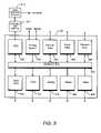
- FIG. 3shows one embodiment of a device for carrying out various principles of the invention.
- FIG. 4shows one example of using a device 301 to reduce contention for resources when a plurality of transmitting sources 401 through 404 are transmitting and/or receiving packets.
- FIG. 5shows a system employing multiple devices coupled together and synchronized to avoid overloading a LAN switch.
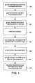
- FIG. 6shows one method for coordinating the transmission of data from the devices shown in FIG. 5 .
- FIG. 7shows one possible transmission map for use in the method of FIG. 6 .
- FIG. 3shows one possible device for carrying out various principles of the present invention.
- the device 301comprises a backplane bus 307 and a CPU 302 that coordinates the scheduling and other activities of the device.
- CPU 302may comprise, for example, an IBM 440GX processor.
- the CPUincludes or is coupled to a local area network, such as an Ethernet via an Ethernet interface that outputs Internet Protocol packets encapsulated in Ethernet frames, as is conventional.
- the Ethernet interfacemay for example comprise a gigabit Ethernet. Other network interfaces are possible, such as a telecommunication interface, or any type of packet interface.
- the packet network interfacemay be coupled to a WAN router 313 for transmission and reception over a Wide Area Network (WAN), such as the Internet.
- WANWide Area Network
- device 301may be directly coupled to WAN network router 313 rather than being connected through device 314 .
- device 301may be directly coupled to the WAN without requiring external devices.
- device 301may be coupled through any packet network interface according to the inventive principles.
- Timing system 303provides clock and interval signals to and from other modules as shown in more detail in FIG. 5 .
- timing system 303works as follows. The timing system will receive a reference timing signal from an external source. In many cases this timing source can be a telecom timing reference or a GPS clock. The timing reference enters the timing system 303 as a clock signal. This clock can be a 1 MHz, 5 MHz or 10 MHz signal. It can also be a T1 or E1 clock.
- the timing system 303employs a set of clock dividers and phase-locked multipliers to generate the clocks needed by each of the modules 304 - 312 in the system of FIG. 3 301 .
- Each modulecan also derive its own timing clock individually by referencing the clock that is provided by the timing system 303 through the backplane 307 .
- the timing system 303can also be commanded, by the CPU 302 , through the backplane 307 to provide timing interrupts at precise intervals, to the CPU 302 . These interrupts can be used to initiate transmission of packets at precise intervals to the Ethernet Network.
- the CPU 302can also use the precise interrupts, to control its access of data from the various modules 304 - 312 . In this way, the CPU can always have sufficient data from each module to create a packet, at the time the CPU has set to transmit the packet.
- a parallel data card 304accepts parallel data from one or more modules and presents the data to CPU 302 via backplane bus 307 .
- Examples of parallel datainclude parallel ports on page printers, scientific instruments and memory loading and CPU emulation devices.
- Asynchronous data card 305accepts asynchronous data from one or more devices and presents the data to CPU 302 via backplane bus 307 . Examples of such data include serial device controllers, communications interfaces to display terminals, keyboards, teletype devices, IR remote control devices, etc.
- data card 305can also transmit asynchronous data to one or more devices from the backplane bus 307 .
- Ethernet data card 306accepts Ethernet data frames (e.g., ad hoc computer data) and presents the data to CPU 302 via backplane bus 307 .
- Video data card 308accepts video analog or digital signals from one or more video devices (e.g., video cameras or the like), converts this into digital data, and may compress the digital data before presenting the data to CPU 302 via backplane bus 307 .
- Stereo card 309accepts stereo analog or digital signals from one or more sources (e.g., CD players, radios, or the like), and may convert the stereo signals to digital data and presents the data to CPU 302 via backplane bus 307 .
- Analog card 310converts analog data (e.g., voice, measurements, or other analog data) into digital form and presents the data to CPU 302 via backplane bus 307 .
- T1/E1 card 311receives data in T1/E1 format from one or more sources and presents it to CPU 302 via backplane bus 307 .
- Synchronous data card 312accepts synchronous data from various sources and presents it to CPU 302 via backplane 307 .
- the various modules shown in FIG. 3are intended to be illustrative only. More or fewer modules may be included, and other types of data beyond those illustrated may be included.
- CPU 302organizes the work that is done by the modules connected to backplane bus 307 .
- CPU 302detects the presence of data at one or more of the modules; retrieves the data in a format suitable for the particular module; reformats the data into Ethernet packet frames; and transmits each packet via Ethernet to an Ethernet LAN switch 314 to a WAN network router 313 , or via Ethernet directly to a WAN network router 313 .
- the datacan be transmitted over the bus using DMA techniques; interrupts; or other methods. Because only one CPU handles the processing, there is no contention for resources.
- CPU 302is also responsible for executing any call establishment protocols. These protocols can include MGCP, H.323, Session Initiation Protocol (SIP), etc. These protocols are used to perform call set up and disconnect.
- SIPSession Initiation Protocol
- FIG. 4shows one example of using a device 301 to reduce contention for resources when a plurality of transmitting sources 401 through 404 are transmitting and/or receiving information.
- Device 301is the same device 301 of FIG. 3 , and is coupled to a plurality of transmitting sources 401 through 404 , such as telephones, and video cameras that transmit video frames.
- each deviceis coupled to device 301 , which reduces congestion by placing packets from each module on the Ethernet using a single CPU and data bus. Realtime data or near-realtime data can thus be handled without losing packets due to LAN contention.
- connectionsare established with devices across the WAN, data flows through the device 301 to and from the devices 401 to 404 .
- FIG. 5shows a system employing multiple devices coupled together.
- multiple endpoint systems 502 - 504can be connected so that they work cooperatively. They can be synchronized to avoid creating congestion or packet loss in a LAN switch.
- each device 501 through 504corresponds to device 301 of FIG. 3 .
- Each deviceincludes a clock/frame interface corresponding to timing circuit 303 of FIG. 3 .
- One of the devices 501is designated as the master, and the others are designated as slaves.
- each device 501 through 504accepts inputs from and generates outputs to multiple devices of various types.
- Each devicegenerates an output to (and receives input via) an Ethernet link to LAN switch 505 , which in turn is linked to a WAN router.
- each device 501 through 504coordinates its schedule such that packets are not transmitted at the same time to LAN switch 505 . Any of various methods can be used to accomplish this, such as assigning time slots for each device to transmit to LAN switch 505 and using the clock/frame interfaces to coordinate this timing.
- FIG. 6shows one method of coordinating a timing schedule among multiple devices to avoid congestion in LAN switch 505 .
- one of the slave devices in FIG. 5queries the master device 501 for a transmission map indicating time slots during which the master and/or other slaves have already allocated packet transmissions.
- a delivery schedulecomprising an arbitrary time period (e.g., one second) can be decomposed into frames, subframes and so forth, and each device can determine based on the bandwidth required to support a particular connection how many time slots are needed to transmit data to and from LAN switch 505 .
- the master deviceresponds in step 602 with a transmission map showing what time slots are available for transmission to LAN switch 505 or, alternatively, what time slots have already been allocated.
- the slavesends a proposed transmission schedule indicating what time slots it proposes to use in order to carry data sufficient to support the various devices it is serving.
- the master deviceagrees to the proposed schedule or proposes an alternate schedule.
- FIG. 7shows one possible implementation of a transmission map, which is essentially a bitmap with each bit corresponding to a time slot.
- step 605the slave device uses the assigned time slots to schedule packets for transmission over the Ethernet to and from LAN switch 505 .
- step 606the slave ends transmission when the connection is no longer needed.
- step 607the slave signals the master to indicate that no further transmission will be required.
- step 608the master removes the slave from the transmission map, freeing up the time slots for other slaves.
- each slave devicecould request a bandwidth and receive from the master a proposed schedule taking into account the proposed bandwidth.
- the slave deviceWhen a slave device receives a request from a distant device to initiate a communications flow, the slave device will begin the process illustrated in FIG. 6 to establish the flow of packets to the distant device. Likewise, the distant device will do the same, at its end, to establish a flow of packets towards the local slave device.
- a virtual connectionis to be established between two nodes on the network to support a telephone voice connection.
- a voice-over-IP connectionmay require a 64 kilobits per second transfer rate. This rate could be accomplished by transmitting one 80-byte payload packet every 10 milliseconds.
- a video streamcould also be established. A video stream would typically impose higher bandwidth requirements on the network. For instance, an MPEG-2 encoded video flow could typically require 8 megabytes per second transfer rate. This could be accomplished on an Ethernet LAN, each packet could comprise up to 1,500 bytes of payload. The video could be transmitted using approximately 13 packets, sent every 10 milliseconds.
- Each devicerepeatedly transmits to the intended recipient according to the agreed delivery schedule.
- the transmittercould transmit an 80-byte packet every 10 milliseconds. It could also transmit a 160 byte packet, at 20 millisecond intervals. For a streaming video connection, more packets are required. In this case the transmitter would transmit larger packets, and groups of them, at a more frequent rate.
Landscapes
- Engineering & Computer Science (AREA)
- Computer Networks & Wireless Communication (AREA)
- Signal Processing (AREA)
- Data Exchanges In Wide-Area Networks (AREA)
- Small-Scale Networks (AREA)
Abstract
Description
Claims (30)
Priority Applications (8)
| Application Number | Priority Date | Filing Date | Title |
|---|---|---|---|
| US10/722,676US7508813B2 (en) | 2003-11-25 | 2003-11-25 | Local area network contention avoidance |
| AU2004296461AAU2004296461A1 (en) | 2003-11-25 | 2004-10-05 | Internet endpoint system |
| CA002546277ACA2546277A1 (en) | 2003-11-25 | 2004-10-05 | Internet endpoint system |
| CNA2004800334897ACN1886943A (en) | 2003-11-25 | 2004-10-05 | Internet endpoint system |
| PCT/US2004/032563WO2005057334A2 (en) | 2003-11-25 | 2004-10-05 | Internet endpoint system |
| EP04794061AEP1690101A2 (en) | 2003-11-25 | 2004-10-05 | Internet endpoint system |
| JP2006541146AJP2007515875A (en) | 2003-11-25 | 2004-10-05 | Internet endpoint system |
| TW093131335ATW200520474A (en) | 2003-11-25 | 2004-10-15 | Internet endpoint system |
Applications Claiming Priority (1)
| Application Number | Priority Date | Filing Date | Title |
|---|---|---|---|
| US10/722,676US7508813B2 (en) | 2003-11-25 | 2003-11-25 | Local area network contention avoidance |
Publications (2)
| Publication Number | Publication Date |
|---|---|
| US20050111357A1 US20050111357A1 (en) | 2005-05-26 |
| US7508813B2true US7508813B2 (en) | 2009-03-24 |
Family
ID=34592039
Family Applications (1)
| Application Number | Title | Priority Date | Filing Date |
|---|---|---|---|
| US10/722,676Expired - LifetimeUS7508813B2 (en) | 2003-11-25 | 2003-11-25 | Local area network contention avoidance |
Country Status (8)
| Country | Link |
|---|---|
| US (1) | US7508813B2 (en) |
| EP (1) | EP1690101A2 (en) |
| JP (1) | JP2007515875A (en) |
| CN (1) | CN1886943A (en) |
| AU (1) | AU2004296461A1 (en) |
| CA (1) | CA2546277A1 (en) |
| TW (1) | TW200520474A (en) |
| WO (1) | WO2005057334A2 (en) |
Cited By (2)
| Publication number | Priority date | Publication date | Assignee | Title |
|---|---|---|---|---|
| US8583735B2 (en) | 2010-11-17 | 2013-11-12 | International Business Machines Corporation | Delivery in session initiated protocol (SIP) conferencing |
| US8824285B1 (en) | 2009-12-16 | 2014-09-02 | Dnutch Associates, Inc. | System and method for collision detection and avoidance during packet based communications |
Families Citing this family (4)
| Publication number | Priority date | Publication date | Assignee | Title |
|---|---|---|---|---|
| US8687628B2 (en)* | 2006-03-16 | 2014-04-01 | Rockstar Consortium USLP | Scalable balanced switches |
| EP2597850A1 (en) | 2011-11-24 | 2013-05-29 | Alcatel Lucent | Method and arrangement for echo cancellation in conference systems |
| CN107979563B (en)* | 2016-10-21 | 2019-05-17 | 视联动力信息技术股份有限公司 | A kind of information processing method and device based on view networking |
| DE102019205488A1 (en)* | 2019-04-16 | 2020-10-22 | Robert Bosch Gmbh | Subscriber station for a serial bus system and method for communication in a serial bus system |
Citations (74)
| Publication number | Priority date | Publication date | Assignee | Title |
|---|---|---|---|---|
| US4745593A (en) | 1986-11-17 | 1988-05-17 | American Telephone And Telegraph Company, At&T Bell Laboratories | Arrangement for testing packet switching networks |
| US4821259A (en) | 1986-09-05 | 1989-04-11 | American Telephone And Telegraph Company, At&T Bell Laboratories | Control information communication arrangement for a distributed control switching system |
| JPH0456322A (en) | 1990-06-26 | 1992-02-24 | Mitsubishi Electric Corp | Heat treatment device |
| US5271000A (en) | 1991-03-22 | 1993-12-14 | International Business Machines Corporation | Method and apparatus for testing and evaluation of distributed networks |
| US5373504A (en) | 1992-04-09 | 1994-12-13 | Fujitsu Limited | Apparatus and a method for setting a communication path |
| US5408465A (en) | 1993-06-21 | 1995-04-18 | Hewlett-Packard Company | Flexible scheme for admission control of multimedia streams on integrated networks |
| US5432775A (en) | 1993-12-03 | 1995-07-11 | Advanced Micro Devices, Inc. | Auto negotiation system for a communications network |
| US5455865A (en) | 1989-05-09 | 1995-10-03 | Digital Equipment Corporation | Robust packet routing over a distributed network containing malicious failures |
| US5477531A (en) | 1991-06-12 | 1995-12-19 | Hewlett-Packard Company | Method and apparatus for testing a packet-based network |
| US5517620A (en) | 1993-05-19 | 1996-05-14 | Nec Corporation | Dynamic updating of routing information for routing packets between LAN's connected to a plurality of routers via a public network |
| US5541921A (en) | 1994-12-06 | 1996-07-30 | National Semiconductor Corporation | Isochronous serial time division multiplexer |
| US5563875A (en) | 1995-07-10 | 1996-10-08 | International Business Machines Corporation | Wrap-around route testing in packet communications networks |
| EP0827307A2 (en) | 1996-08-22 | 1998-03-04 | International Business Machines Corporation | Adaptive rate-based congestion control in packet networks |
| US5734656A (en) | 1995-07-12 | 1998-03-31 | Bay Networks, Inc. | Method and apparatus for dynamically allocating bandwidth on a TDM bus |
| US5774668A (en) | 1995-06-07 | 1998-06-30 | Microsoft Corporation | System for on-line service in which gateway computer uses service map which includes loading condition of servers broadcasted by application servers for load balancing |
| US5781534A (en) | 1995-10-31 | 1998-07-14 | Novell, Inc. | Method and apparatus for determining characteristics of a path |
| US5859835A (en) | 1996-04-15 | 1999-01-12 | The Regents Of The University Of California | Traffic scheduling system and method for packet-switched networks |
| US5859979A (en) | 1993-11-24 | 1999-01-12 | Intel Corporation | System for negotiating conferencing capabilities by selecting a subset of a non-unique set of conferencing capabilities to specify a unique set of conferencing capabilities |
| US5917822A (en) | 1995-11-15 | 1999-06-29 | Xerox Corporation | Method for providing integrated packet services over a shared-media network |
| US5974056A (en)* | 1996-01-10 | 1999-10-26 | Frequentis Nachrichtentechnik Gesellschaft M.B.H. | Method of and apparatus for transmission of data |
| US6047054A (en) | 1994-11-01 | 2000-04-04 | Davox Corporation | Computer telephone system |
| US6058117A (en) | 1997-10-27 | 2000-05-02 | Cisco Technology, Inc. | Data transfer via pseudo deterministic channel |
| WO2000028705A1 (en) | 1998-11-10 | 2000-05-18 | Odyssia Systems, Inc. | Method and apparatus for interconnection of packet switches with guaranteed bandwidth |
| WO2000028706A1 (en) | 1998-11-10 | 2000-05-18 | Odyssia Systems, Inc. | Method and apparatus to minimize congestion in a packet switched network |
| US6067572A (en) | 1996-11-07 | 2000-05-23 | Novell, Inc. | Extrinsically influenced near-optimal path apparatus and method |
| US6088361A (en) | 1997-05-06 | 2000-07-11 | International Business Machines Corp. | Timed division multiplex bus connection controller |
| US6134589A (en) | 1997-06-16 | 2000-10-17 | Telefonaktiebolaget Lm Ericsson | Dynamic quality control network routing |
| US6141355A (en)* | 1998-11-06 | 2000-10-31 | Path 1 Network Technologies, Inc. | Time-synchronized multi-layer network switch for providing quality of service guarantees in computer networks |
| US6208666B1 (en) | 1997-11-04 | 2001-03-27 | Geogia Tech Research Corporation | System and method for maintaining timing synchronization in a digital video network |
| US6240084B1 (en)* | 1996-10-10 | 2001-05-29 | Cisco Systems, Inc. | Telephony-enabled network processing device with separate TDM bus and host system backplane bus |
| US6247061B1 (en) | 1998-06-09 | 2001-06-12 | Microsoft Corporation | Method and computer program product for scheduling network communication packets originating from different flows having unique service requirements |
| WO2001047162A1 (en) | 1999-12-23 | 2001-06-28 | Cetacean Networks, Inc. | Network switch with packet scheduling |
| WO2001050146A1 (en) | 2000-01-06 | 2001-07-12 | Cetacean Networks, Inc. | Local area network (lan) packet switch remote power system |
| US6272131B1 (en)* | 1998-06-11 | 2001-08-07 | Synchrodyne Networks, Inc. | Integrated data packet network using a common time reference |
| WO2001060029A1 (en) | 2000-02-08 | 2001-08-16 | Cetacean Networks, Inc. | Speakerphone accessory for a telephone instrument |
| US20020010792A1 (en) | 2000-07-21 | 2002-01-24 | John Border | Method and system for improving network performance by utilizing path selection, path activation, and profiles |
| US6359885B1 (en) | 1997-08-27 | 2002-03-19 | Electronics And Telecommunications Research Institute | Multi-channel packet switching apparatus having traffic flow controlling and checking functions |
| US6373822B1 (en) | 1999-01-08 | 2002-04-16 | Cisco Technology, Inc. | Data network protocol conformance test system |
| US6377579B1 (en) | 1998-06-11 | 2002-04-23 | Synchrodyne Networks, Inc. | Interconnecting a synchronous switching network that utilizes a common time reference with an asynchronous switching network |
| US6385198B1 (en) | 1998-06-11 | 2002-05-07 | Synchrodyne Networks, Inc. | Signaling for timely forwarding in packet switching network with a common time reference |
| US20020054611A1 (en) | 1998-07-07 | 2002-05-09 | Mitsuru Seta | Time synchronization method in cdma system |
| WO2002041505A2 (en) | 2000-11-16 | 2002-05-23 | Broadcom Corporation | Method and apparatus for detection and classification of impairments on an rf modulated network |
| US20020080719A1 (en) | 2000-12-22 | 2002-06-27 | Stefan Parkvall | Scheduling transmission of data over a transmission channel based on signal quality of a receive channel |
| US6426814B1 (en) | 1999-10-13 | 2002-07-30 | Caly Corporation | Spatially switched router for wireless data packets |
| US6426944B1 (en) | 1998-12-30 | 2002-07-30 | At&T Corp | Method and apparatus for controlling data messages across a fast packet network |
| US20020110129A1 (en) | 2001-02-09 | 2002-08-15 | Naoki Matsuoka | Scheduling method and scheduling apparatus |
| US6487593B2 (en) | 1998-12-24 | 2002-11-26 | International Business Machines Corporation | Data processing with distributed messaging problem determination |
| WO2002100023A2 (en) | 2001-06-05 | 2002-12-12 | Cetacean Networks, Inc. | Real-time network scheduled packet routing system |
| US20020186660A1 (en) | 2001-06-12 | 2002-12-12 | Bahadiroglu Murat I. | Adaptive control of data packet size in networks |
| US6496477B1 (en) | 1999-07-09 | 2002-12-17 | Texas Instruments Incorporated | Processes, articles, and packets for network path diversity in media over packet applications |
| US6502135B1 (en) | 1998-10-30 | 2002-12-31 | Science Applications International Corporation | Agile network protocol for secure communications with assured system availability |
| US6529480B1 (en) | 1999-08-19 | 2003-03-04 | National Semiconductor Corporation | Self-test for 10/100 Mbit ethernet physical layer devices |
| US20030058880A1 (en) | 2001-09-21 | 2003-03-27 | Terago Communications, Inc. | Multi-service queuing method and apparatus that provides exhaustive arbitration, load balancing, and support for rapid port failover |
| US20030067903A1 (en) | 1998-07-10 | 2003-04-10 | Jorgensen Jacob W. | Method and computer program product for internet protocol (IP)-flow classification in a wireless point to multi-point (PTMP) |
| US6560222B1 (en) | 1998-04-03 | 2003-05-06 | Vertical Networks, Inc. | Systems and methods for multiple voice and data communications using intelligently bridged TDM and packet buses and methods for performing telephony and data functions using the same |
| US6574193B1 (en) | 1999-07-28 | 2003-06-03 | Veraz Networks Ltd. | Congestion control using variable rate encoding based on queue fill |
| US20030107991A1 (en) | 2001-12-12 | 2003-06-12 | Yasuo Tezuka | Congestion control system for VoIP network |
| US20030117959A1 (en) | 2001-12-10 | 2003-06-26 | Igor Taranov | Methods and apparatus for placement of test packets onto a data communication network |
| US6611519B1 (en)* | 1998-08-19 | 2003-08-26 | Swxtch The Rules, Llc | Layer one switching in a packet, cell, or frame-based network |
| US6618360B1 (en) | 1999-06-15 | 2003-09-09 | Hewlett-Packard Development Company, L.P. | Method for testing data path of peripheral server devices |
| US6628629B1 (en) | 1998-07-10 | 2003-09-30 | Malibu Networks | Reservation based prioritization method for wireless transmission of latency and jitter sensitive IP-flows in a wireless point to multi-point transmission system |
| US20030188188A1 (en) | 2002-03-15 | 2003-10-02 | Microsoft Corporation | Time-window-constrained multicast for future delivery multicast |
| WO2003084137A2 (en) | 2002-03-29 | 2003-10-09 | Network Genomics, Inc. | Methods for identifying network traffic flows |
| US6633544B1 (en) | 1998-06-24 | 2003-10-14 | At&T Corp. | Efficient precomputation of quality-of-service routes |
| US20030219029A1 (en) | 1998-04-03 | 2003-11-27 | Pickett Scott K. | Systems and methods for multiple mode voice and data communications using intelligently bridged TDM and packet buses and methods for performing telephony and data functions using the same |
| US20040008655A1 (en) | 2002-06-26 | 2004-01-15 | Park Sung K. | Scheduling method and apparatus for combined code division multiplexing and time division multiplexing |
| US20040014491A1 (en) | 2002-04-15 | 2004-01-22 | Weigand Gilbert G. | Dynamically managing and reconfiguring wireless mesh networks |
| US20040024550A1 (en) | 2000-09-19 | 2004-02-05 | Heinrich Doerken | Method for measuring unidirectional transmission characteristics such as packet propagation time, fluctuations in propagation time and results derivable therefrom, in a telecommunications network |
| JP2004056322A (en) | 2002-07-18 | 2004-02-19 | Victor Co Of Japan Ltd | Network management apparatus and computer program |
| US6711137B1 (en) | 1999-03-12 | 2004-03-23 | International Business Machines Corporation | System and method for analyzing and tuning a communications network |
| US6731600B1 (en) | 1999-02-08 | 2004-05-04 | Realnetworks, Inc. | System and method for determining network conditions |
| US6778536B1 (en) | 1999-11-09 | 2004-08-17 | Synchrodyne Networks, Inc. | Combined wavelength division multiplexing, time division multiplexing, and asynchronous packet switching with common time reference |
| US20040160340A1 (en)* | 2003-02-17 | 2004-08-19 | Thomson Deane A. | Methods and apparatus for transportation vehicle security monitoring |
| US20040179530A1 (en) | 1997-12-08 | 2004-09-16 | Alcatel | Signalling between ATM and local area networks |
Family Cites Families (20)
| Publication number | Priority date | Publication date | Assignee | Title |
|---|---|---|---|---|
| US219029A (en)* | 1879-08-26 | Improvement in plows | ||
| US426944A (en)* | 1890-04-29 | The art of boxing | ||
| US186660A (en)* | 1877-01-30 | Improvement in road-scrapers | ||
| US117959A (en)* | 1871-08-15 | Improvement in brooms | ||
| US179530A (en)* | 1876-07-04 | Improvement in keyed violins, cellos | ||
| US110129A (en)* | 1870-12-13 | Improvement in notes, checks | ||
| US188188A (en)* | 1877-03-06 | Improvement in liquid-measures | ||
| US54611A (en)* | 1866-05-08 | Improvement in harvesters | ||
| US67903A (en)* | 1867-08-20 | Adolph philippi | ||
| US80719A (en)* | 1868-08-04 | John f | ||
| US8655A (en)* | 1852-01-13 | Bevelihg-plahe | ||
| US14491A (en)* | 1856-03-25 | Improvement in breech - loading fire-arms | ||
| US191592A (en)* | 1877-06-05 | Improvement in fulling-mills | ||
| US10792A (en)* | 1854-04-18 | Machine foe cleaning blinds | ||
| US58880A (en)* | 1866-10-16 | Improvement in drop-presses | ||
| US86641A (en)* | 1869-02-09 | Sylvania | ||
| US6480506B1 (en)* | 1999-04-15 | 2002-11-12 | Sharewave Inc | Co-location negotiation scheme for wireless computer networks |
| US7269152B2 (en)* | 2003-02-14 | 2007-09-11 | Motorola, Inc. | Method and apparatus for transmitting information within a communication system |
| US7529247B2 (en)* | 2003-09-17 | 2009-05-05 | Rivulet Communications, Inc. | Empirical scheduling of network packets |
| US7468948B2 (en)* | 2003-09-17 | 2008-12-23 | Steven A Rogers | Empirical scheduling of network packets using coarse and fine testing periods |
- 2003
- 2003-11-25USUS10/722,676patent/US7508813B2/ennot_activeExpired - Lifetime
- 2004
- 2004-10-05EPEP04794061Apatent/EP1690101A2/ennot_activeWithdrawn
- 2004-10-05WOPCT/US2004/032563patent/WO2005057334A2/ennot_activeApplication Discontinuation
- 2004-10-05AUAU2004296461Apatent/AU2004296461A1/ennot_activeAbandoned
- 2004-10-05CNCNA2004800334897Apatent/CN1886943A/enactivePending
- 2004-10-05JPJP2006541146Apatent/JP2007515875A/ennot_activeWithdrawn
- 2004-10-05CACA002546277Apatent/CA2546277A1/ennot_activeAbandoned
- 2004-10-15TWTW093131335Apatent/TW200520474A/enunknown
Patent Citations (83)
| Publication number | Priority date | Publication date | Assignee | Title |
|---|---|---|---|---|
| US4821259A (en) | 1986-09-05 | 1989-04-11 | American Telephone And Telegraph Company, At&T Bell Laboratories | Control information communication arrangement for a distributed control switching system |
| US4745593A (en) | 1986-11-17 | 1988-05-17 | American Telephone And Telegraph Company, At&T Bell Laboratories | Arrangement for testing packet switching networks |
| US5455865A (en) | 1989-05-09 | 1995-10-03 | Digital Equipment Corporation | Robust packet routing over a distributed network containing malicious failures |
| JPH0456322A (en) | 1990-06-26 | 1992-02-24 | Mitsubishi Electric Corp | Heat treatment device |
| US5271000A (en) | 1991-03-22 | 1993-12-14 | International Business Machines Corporation | Method and apparatus for testing and evaluation of distributed networks |
| US5477531A (en) | 1991-06-12 | 1995-12-19 | Hewlett-Packard Company | Method and apparatus for testing a packet-based network |
| US5373504A (en) | 1992-04-09 | 1994-12-13 | Fujitsu Limited | Apparatus and a method for setting a communication path |
| US5517620A (en) | 1993-05-19 | 1996-05-14 | Nec Corporation | Dynamic updating of routing information for routing packets between LAN's connected to a plurality of routers via a public network |
| US5408465A (en) | 1993-06-21 | 1995-04-18 | Hewlett-Packard Company | Flexible scheme for admission control of multimedia streams on integrated networks |
| US5859979A (en) | 1993-11-24 | 1999-01-12 | Intel Corporation | System for negotiating conferencing capabilities by selecting a subset of a non-unique set of conferencing capabilities to specify a unique set of conferencing capabilities |
| US5610903A (en) | 1993-12-03 | 1997-03-11 | Advanced Micro Devices, Inc. | Auto negotiation system for a communications network |
| US5432775A (en) | 1993-12-03 | 1995-07-11 | Advanced Micro Devices, Inc. | Auto negotiation system for a communications network |
| US6047054A (en) | 1994-11-01 | 2000-04-04 | Davox Corporation | Computer telephone system |
| US5541921A (en) | 1994-12-06 | 1996-07-30 | National Semiconductor Corporation | Isochronous serial time division multiplexer |
| US5774668A (en) | 1995-06-07 | 1998-06-30 | Microsoft Corporation | System for on-line service in which gateway computer uses service map which includes loading condition of servers broadcasted by application servers for load balancing |
| US5563875A (en) | 1995-07-10 | 1996-10-08 | International Business Machines Corporation | Wrap-around route testing in packet communications networks |
| US5734656A (en) | 1995-07-12 | 1998-03-31 | Bay Networks, Inc. | Method and apparatus for dynamically allocating bandwidth on a TDM bus |
| US5781534A (en) | 1995-10-31 | 1998-07-14 | Novell, Inc. | Method and apparatus for determining characteristics of a path |
| US5917822A (en) | 1995-11-15 | 1999-06-29 | Xerox Corporation | Method for providing integrated packet services over a shared-media network |
| US5974056A (en)* | 1996-01-10 | 1999-10-26 | Frequentis Nachrichtentechnik Gesellschaft M.B.H. | Method of and apparatus for transmission of data |
| US5859835A (en) | 1996-04-15 | 1999-01-12 | The Regents Of The University Of California | Traffic scheduling system and method for packet-switched networks |
| EP0827307A2 (en) | 1996-08-22 | 1998-03-04 | International Business Machines Corporation | Adaptive rate-based congestion control in packet networks |
| US6240084B1 (en)* | 1996-10-10 | 2001-05-29 | Cisco Systems, Inc. | Telephony-enabled network processing device with separate TDM bus and host system backplane bus |
| US6067572A (en) | 1996-11-07 | 2000-05-23 | Novell, Inc. | Extrinsically influenced near-optimal path apparatus and method |
| US6088361A (en) | 1997-05-06 | 2000-07-11 | International Business Machines Corp. | Timed division multiplex bus connection controller |
| US6134589A (en) | 1997-06-16 | 2000-10-17 | Telefonaktiebolaget Lm Ericsson | Dynamic quality control network routing |
| US6359885B1 (en) | 1997-08-27 | 2002-03-19 | Electronics And Telecommunications Research Institute | Multi-channel packet switching apparatus having traffic flow controlling and checking functions |
| US6058117A (en) | 1997-10-27 | 2000-05-02 | Cisco Technology, Inc. | Data transfer via pseudo deterministic channel |
| US6208666B1 (en) | 1997-11-04 | 2001-03-27 | Geogia Tech Research Corporation | System and method for maintaining timing synchronization in a digital video network |
| US20040179530A1 (en) | 1997-12-08 | 2004-09-16 | Alcatel | Signalling between ATM and local area networks |
| US6560222B1 (en) | 1998-04-03 | 2003-05-06 | Vertical Networks, Inc. | Systems and methods for multiple voice and data communications using intelligently bridged TDM and packet buses and methods for performing telephony and data functions using the same |
| US20030219029A1 (en) | 1998-04-03 | 2003-11-27 | Pickett Scott K. | Systems and methods for multiple mode voice and data communications using intelligently bridged TDM and packet buses and methods for performing telephony and data functions using the same |
| US6247061B1 (en) | 1998-06-09 | 2001-06-12 | Microsoft Corporation | Method and computer program product for scheduling network communication packets originating from different flows having unique service requirements |
| US6377579B1 (en) | 1998-06-11 | 2002-04-23 | Synchrodyne Networks, Inc. | Interconnecting a synchronous switching network that utilizes a common time reference with an asynchronous switching network |
| US6272131B1 (en)* | 1998-06-11 | 2001-08-07 | Synchrodyne Networks, Inc. | Integrated data packet network using a common time reference |
| US6385198B1 (en) | 1998-06-11 | 2002-05-07 | Synchrodyne Networks, Inc. | Signaling for timely forwarding in packet switching network with a common time reference |
| US6633544B1 (en) | 1998-06-24 | 2003-10-14 | At&T Corp. | Efficient precomputation of quality-of-service routes |
| US20020054611A1 (en) | 1998-07-07 | 2002-05-09 | Mitsuru Seta | Time synchronization method in cdma system |
| US6628629B1 (en) | 1998-07-10 | 2003-09-30 | Malibu Networks | Reservation based prioritization method for wireless transmission of latency and jitter sensitive IP-flows in a wireless point to multi-point transmission system |
| US20030067903A1 (en) | 1998-07-10 | 2003-04-10 | Jorgensen Jacob W. | Method and computer program product for internet protocol (IP)-flow classification in a wireless point to multi-point (PTMP) |
| US6611519B1 (en)* | 1998-08-19 | 2003-08-26 | Swxtch The Rules, Llc | Layer one switching in a packet, cell, or frame-based network |
| US6618761B2 (en) | 1998-10-30 | 2003-09-09 | Science Applications International Corp. | Agile network protocol for secure communications with assured system availability |
| US6502135B1 (en) | 1998-10-30 | 2002-12-31 | Science Applications International Corporation | Agile network protocol for secure communications with assured system availability |
| US6141355A (en)* | 1998-11-06 | 2000-10-31 | Path 1 Network Technologies, Inc. | Time-synchronized multi-layer network switch for providing quality of service guarantees in computer networks |
| WO2000028706A1 (en) | 1998-11-10 | 2000-05-18 | Odyssia Systems, Inc. | Method and apparatus to minimize congestion in a packet switched network |
| WO2000028705A1 (en) | 1998-11-10 | 2000-05-18 | Odyssia Systems, Inc. | Method and apparatus for interconnection of packet switches with guaranteed bandwidth |
| US6487593B2 (en) | 1998-12-24 | 2002-11-26 | International Business Machines Corporation | Data processing with distributed messaging problem determination |
| US6426944B1 (en) | 1998-12-30 | 2002-07-30 | At&T Corp | Method and apparatus for controlling data messages across a fast packet network |
| US6373822B1 (en) | 1999-01-08 | 2002-04-16 | Cisco Technology, Inc. | Data network protocol conformance test system |
| US6731600B1 (en) | 1999-02-08 | 2004-05-04 | Realnetworks, Inc. | System and method for determining network conditions |
| US6711137B1 (en) | 1999-03-12 | 2004-03-23 | International Business Machines Corporation | System and method for analyzing and tuning a communications network |
| US6618360B1 (en) | 1999-06-15 | 2003-09-09 | Hewlett-Packard Development Company, L.P. | Method for testing data path of peripheral server devices |
| US6496477B1 (en) | 1999-07-09 | 2002-12-17 | Texas Instruments Incorporated | Processes, articles, and packets for network path diversity in media over packet applications |
| US6574193B1 (en) | 1999-07-28 | 2003-06-03 | Veraz Networks Ltd. | Congestion control using variable rate encoding based on queue fill |
| US6529480B1 (en) | 1999-08-19 | 2003-03-04 | National Semiconductor Corporation | Self-test for 10/100 Mbit ethernet physical layer devices |
| US6426814B1 (en) | 1999-10-13 | 2002-07-30 | Caly Corporation | Spatially switched router for wireless data packets |
| US6778536B1 (en) | 1999-11-09 | 2004-08-17 | Synchrodyne Networks, Inc. | Combined wavelength division multiplexing, time division multiplexing, and asynchronous packet switching with common time reference |
| WO2001047162A1 (en) | 1999-12-23 | 2001-06-28 | Cetacean Networks, Inc. | Network switch with packet scheduling |
| WO2001050146A1 (en) | 2000-01-06 | 2001-07-12 | Cetacean Networks, Inc. | Local area network (lan) packet switch remote power system |
| US6556564B2 (en) | 2000-02-08 | 2003-04-29 | Cetacean Networks, Inc. | Scheduled internet protocol telephone instrument system |
| WO2001060029A1 (en) | 2000-02-08 | 2001-08-16 | Cetacean Networks, Inc. | Speakerphone accessory for a telephone instrument |
| US20010033565A1 (en) | 2000-02-08 | 2001-10-25 | Cetacean Networks, Inc. | Scheduled internet protocol telephone instrument system |
| US20010033649A1 (en) | 2000-02-08 | 2001-10-25 | Cetacean Networks, Inc. | Speakerphone accessory for a telephone instrument |
| WO2001059994A1 (en) | 2000-02-08 | 2001-08-16 | Cetacean Networks, Inc. | Scheduled internet protocol telephone instrument system |
| US20020010792A1 (en) | 2000-07-21 | 2002-01-24 | John Border | Method and system for improving network performance by utilizing path selection, path activation, and profiles |
| US20040024550A1 (en) | 2000-09-19 | 2004-02-05 | Heinrich Doerken | Method for measuring unidirectional transmission characteristics such as packet propagation time, fluctuations in propagation time and results derivable therefrom, in a telecommunications network |
| US20020086641A1 (en) | 2000-11-16 | 2002-07-04 | Howard Daniel H. | Method and apparatus for detection and classification of impairments on an RF modulated network |
| WO2002041505A2 (en) | 2000-11-16 | 2002-05-23 | Broadcom Corporation | Method and apparatus for detection and classification of impairments on an rf modulated network |
| US20020080719A1 (en) | 2000-12-22 | 2002-06-27 | Stefan Parkvall | Scheduling transmission of data over a transmission channel based on signal quality of a receive channel |
| US20020110129A1 (en) | 2001-02-09 | 2002-08-15 | Naoki Matsuoka | Scheduling method and scheduling apparatus |
| WO2002100023A3 (en) | 2001-06-05 | 2003-02-27 | Cetacean Networks Inc | Real-time network scheduled packet routing system |
| US20020191592A1 (en) | 2001-06-05 | 2002-12-19 | Rogers Steven A. | Real-time network scheduled packet routing system |
| WO2002100023A2 (en) | 2001-06-05 | 2002-12-12 | Cetacean Networks, Inc. | Real-time network scheduled packet routing system |
| US20020186660A1 (en) | 2001-06-12 | 2002-12-12 | Bahadiroglu Murat I. | Adaptive control of data packet size in networks |
| US20030058880A1 (en) | 2001-09-21 | 2003-03-27 | Terago Communications, Inc. | Multi-service queuing method and apparatus that provides exhaustive arbitration, load balancing, and support for rapid port failover |
| US20030117959A1 (en) | 2001-12-10 | 2003-06-26 | Igor Taranov | Methods and apparatus for placement of test packets onto a data communication network |
| US20030107991A1 (en) | 2001-12-12 | 2003-06-12 | Yasuo Tezuka | Congestion control system for VoIP network |
| US20030188188A1 (en) | 2002-03-15 | 2003-10-02 | Microsoft Corporation | Time-window-constrained multicast for future delivery multicast |
| WO2003084137A2 (en) | 2002-03-29 | 2003-10-09 | Network Genomics, Inc. | Methods for identifying network traffic flows |
| US20040014491A1 (en) | 2002-04-15 | 2004-01-22 | Weigand Gilbert G. | Dynamically managing and reconfiguring wireless mesh networks |
| US20040008655A1 (en) | 2002-06-26 | 2004-01-15 | Park Sung K. | Scheduling method and apparatus for combined code division multiplexing and time division multiplexing |
| JP2004056322A (en) | 2002-07-18 | 2004-02-19 | Victor Co Of Japan Ltd | Network management apparatus and computer program |
| US20040160340A1 (en)* | 2003-02-17 | 2004-08-19 | Thomson Deane A. | Methods and apparatus for transportation vehicle security monitoring |
Non-Patent Citations (12)
| Title |
|---|
| Business Communications Review; Sep. 2003; "Circuit-y New Choices for IP Networks" pp. 18-24. |
| Cetacean Networks; www.cetacean.com; "Cost-Effective IP Networks for High Quality Videoconferencing" Nov. 2002; pp. 1-9. |
| Clark, M; Jeffay, K; Application -level Measurements of Performance on the vBNS Multimedia Computing and Systems, 1999. IEEE International Conference on Jun. 1999, vol. 2, 7-11, pp. 362-366 vol. 2. |
| Copyright @ 2001; Practical Limits on Network Utilization in Converged IP Networks; Sean S.B. Moore, Ph.D. ; Cetacean Networks, Inc.; pp. 1-2. |
| Copyright @ 2003, Cetacean Networks, Inc.; A Deterministic Protocol for QoS in IP Networks: Packet Sequencing; Steven A. Rogers, Sean S.B. Moore, Ph.D. and Curtis A. Siller, Jr. Ph.D.; Abstract pp. 1-18. |
| Copyright @ 2003; Packet Sequencing: IP Networks; Sean S.B. Moore, Ph.D.; Cetacean Networks, Inc.; pp. 98-107. |
| Distributed Path Reservation Algorithms for Multiplexed all-Optical Interconnection Networks; X, Yuan, R. Melhem and R. Gupta; Abstract; 10pages. |
| IEEE Communications Magazine Oct. 2003; Topics in Internet Technology; "Packet Sequencing a Deterministic Protocol for Qos in IP Networks"; Sean S. B. Moore and Curtis A. Siller, Jr., Cetacean Networks, Inc; Abstract pp. 98-107. |
| Packet Sequencing: A Layer -2 Wan Switching Technology for Per-Flow Ideal QoS and Secure IP Networking; Steven A. Rogers, Sean S.B. Moore and Curtis A. Siller, Jr.; Abstract pp. 1-6. |
| Self-Adjusted Network Transmission for Multimedia Data; Mei-Ling Shyu, Shu-Ching Chen, Hongli Luo; Abstract; 6pages. |
| The Desk Area Network;; Mark Hayter and Derek McAuley; May 1991;Abstract pp. 11. |
| The Problem of Upstream Traffic Synchronization in Passive Optical Networks; Glen Kramer; Abstract pp. 1-7. |
Cited By (3)
| Publication number | Priority date | Publication date | Assignee | Title |
|---|---|---|---|---|
| US8824285B1 (en) | 2009-12-16 | 2014-09-02 | Dnutch Associates, Inc. | System and method for collision detection and avoidance during packet based communications |
| US9553828B1 (en) | 2009-12-16 | 2017-01-24 | Dnutch Associates, Inc. | System and method for collision detection and avoidance for network communications |
| US8583735B2 (en) | 2010-11-17 | 2013-11-12 | International Business Machines Corporation | Delivery in session initiated protocol (SIP) conferencing |
Also Published As
| Publication number | Publication date |
|---|---|
| EP1690101A2 (en) | 2006-08-16 |
| AU2004296461A1 (en) | 2005-06-23 |
| CN1886943A (en) | 2006-12-27 |
| WO2005057334A3 (en) | 2005-11-24 |
| CA2546277A1 (en) | 2005-06-23 |
| JP2007515875A (en) | 2007-06-14 |
| US20050111357A1 (en) | 2005-05-26 |
| TW200520474A (en) | 2005-06-16 |
| WO2005057334A2 (en) | 2005-06-23 |
Similar Documents
| Publication | Publication Date | Title |
|---|---|---|
| US7453885B2 (en) | Network connection device | |
| US6377579B1 (en) | Interconnecting a synchronous switching network that utilizes a common time reference with an asynchronous switching network | |
| US6754210B1 (en) | Shared medium access scheduling with common time reference | |
| US6885664B2 (en) | Distributed switching system and method with time-based routing | |
| US4586175A (en) | Method for operating a packet bus for transmission of asynchronous and pseudo-synchronous signals | |
| JPH06216908A (en) | Network for transmitting isochronous source data having frame structure | |
| US5610920A (en) | Coupling of voice and computer resources over networks | |
| US7529247B2 (en) | Empirical scheduling of network packets | |
| CN101297203A (en) | Compressed Video Packet Scheduling System | |
| JP2000101609A (en) | Device for, synchronization of synchronous traffic stream sent out by asynchronous medium | |
| CN115296764A (en) | Timestamp confidence level | |
| US7339923B2 (en) | Endpoint packet scheduling system | |
| KR20070053654A (en) | Method and apparatus for isochronous datagram delivery over competitive system data links | |
| CN1668029B (en) | Method, apparatus and system for the synchronized combining of packet data | |
| US12267248B2 (en) | Network infrastructure device, communication terminal and method for synchronizing control applications via a communication network for transferring time-critical data | |
| US7508813B2 (en) | Local area network contention avoidance | |
| JP2000183922A (en) | Device for synchronizing plural streams of synchronous traffic supplied by asynchronous medium | |
| EP1292083A2 (en) | Method for processing requests in a network adaptor | |
| JP2016503615A (en) | Real-time message transmission method and computer network for transmitting real-time messages | |
| JP4200133B2 (en) | Data link layer device for serial communication bus | |
| KR100419281B1 (en) | Transmitting Data Processor (TDP) and control method based on PMC in the Central Station for the Satellite Communication Systems | |
| CN218217375U (en) | Accurate synchronous scheduling device for large-batch controlled receivers | |
| US9231984B1 (en) | Systems and methods for hair pinning time-division multiplexing calls across time domains | |
| US20030016693A1 (en) | Buffering in packet-TDM systems | |
| JP2003324476A (en) | IP packet transmission system |
Legal Events
| Date | Code | Title | Description |
|---|---|---|---|
| AS | Assignment | Owner name:RIVULET COMMUNICATIONS, INC., NEW HAMPSHIRE Free format text:ASSIGNMENT OF ASSIGNORS INTEREST;ASSIGNOR:ROGERS, STEVEN A.;REEL/FRAME:015764/0836 Effective date:20040901 | |
| AS | Assignment | Owner name:TMG-RIVULET PARTNERSHIP, CALIFORNIA Free format text:SECURITY AGREEMENT;ASSIGNOR:RIVULET COMMUNICATIONS, INC.;REEL/FRAME:015263/0314 Effective date:20041018 | |
| AS | Assignment | Owner name:RIVULET COMMUNICATIONS INC, NEW HAMPSHIRE Free format text:ASSIGNMENT OF ASSIGNORS INTEREST;ASSIGNOR:ROGERS, STEVEN A;REEL/FRAME:015434/0499 Effective date:20040901 | |
| AS | Assignment | Owner name:RIVULET COMMUNICATIONS, INC., A DELAWARE CORP., NE Free format text:RELEASE BY SECURED PARTY;ASSIGNOR:TMG-RIVULET PARTNERSHIP;REEL/FRAME:015994/0328 Effective date:20050331 | |
| STCF | Information on status: patent grant | Free format text:PATENTED CASE | |
| AS | Assignment | Owner name:HERCULES TECHNOLOGY GROWTH CAPITAL, INC., CALIFORN Free format text:SECURITY AGREEMENT;ASSIGNOR:RIVULET COMMUNICATIONS, INC.;REEL/FRAME:022390/0039 Effective date:20090127 | |
| AS | Assignment | Owner name:NDS IMAGING HOLDINGS, LLC,CALIFORNIA Free format text:ASSIGNMENT OF ASSIGNORS INTEREST;ASSIGNOR:HERCULES TECHNOLOGY GROWTH CAPITAL, INC.;REEL/FRAME:024170/0819 Effective date:20100401 | |
| AS | Assignment | Owner name:MCG CAPITAL CORPORATION, AS ADMINISTRATIVE AGENT,V Free format text:NOTICE OF GRANT OF SECURITY INTEREST IN PATENTS;ASSIGNOR:NDS IMAGING HOLDINGS, LLC;REEL/FRAME:024358/0624 Effective date:20051207 Owner name:MCG CAPITAL CORPORATION, AS ADMINISTRATIVE AGENT, Free format text:NOTICE OF GRANT OF SECURITY INTEREST IN PATENTS;ASSIGNOR:NDS IMAGING HOLDINGS, LLC;REEL/FRAME:024358/0624 Effective date:20051207 | |
| AS | Assignment | Owner name:MCG CAPITAL CORPORATION, AS COLLATERAL AGENT,VIRGI Free format text:CORRECTIVE ASSIGNMENT TO CORRECT THE CAPACITY OF MCG CAPITAL CORPORATION FROM ADMINISTRATIVE AGENT TO COLLATERAL AGENT PREVIOUSLY RECORDED ON REEL 024358 FRAME 0624. ASSIGNOR(S) HEREBY CONFIRMS THE NOTICE OF GRANT OF SECURITY INTEREST IN PATENTS AS A TRUE AND CORRECT COPY OF THE ORIGINAL;ASSIGNOR:NDS IMAGING HOLDINGS, LLC;REEL/FRAME:024588/0113 Effective date:20051207 Owner name:MCG CAPITAL CORPORATION, AS COLLATERAL AGENT, VIRG Free format text:CORRECTIVE ASSIGNMENT TO CORRECT THE CAPACITY OF MCG CAPITAL CORPORATION FROM ADMINISTRATIVE AGENT TO COLLATERAL AGENT PREVIOUSLY RECORDED ON REEL 024358 FRAME 0624. ASSIGNOR(S) HEREBY CONFIRMS THE NOTICE OF GRANT OF SECURITY INTEREST IN PATENTS AS A TRUE AND CORRECT COPY OF THE ORIGINAL;ASSIGNOR:NDS IMAGING HOLDINGS, LLC;REEL/FRAME:024588/0113 Effective date:20051207 | |
| FPAY | Fee payment | Year of fee payment:4 | |
| AS | Assignment | Owner name:NDSSI IP HOLDINGS, LLC, CALIFORNIA Free format text:RELEASE BY SECURED PARTY;ASSIGNOR:MCG CAPITAL CORPORATION;REEL/FRAME:029658/0584 Effective date:20130115 Owner name:NDS SURGICAL IMAGING, LLC (FORMERLY NATIONAL DISPL Free format text:RELEASE BY SECURED PARTY;ASSIGNOR:MCG CAPITAL CORPORATION;REEL/FRAME:029658/0584 Effective date:20130115 Owner name:NDS SURGICAL IMAGING, INC. (FORMERLY DOME IMAGING Free format text:RELEASE BY SECURED PARTY;ASSIGNOR:MCG CAPITAL CORPORATION;REEL/FRAME:029658/0584 Effective date:20130115 Owner name:NDSSI HOLDINGS, LLC (FORMERLY NATIONAL DISPLAY HOL Free format text:RELEASE BY SECURED PARTY;ASSIGNOR:MCG CAPITAL CORPORATION;REEL/FRAME:029658/0584 Effective date:20130115 Owner name:NDS IMAGING HOLDINGS, LLC, CALIFORNIA Free format text:RELEASE BY SECURED PARTY;ASSIGNOR:MCG CAPITAL CORPORATION;REEL/FRAME:029658/0584 Effective date:20130115 | |
| AS | Assignment | Owner name:BANK OF AMERICA, N.A., ILLINOIS Free format text:SECURITY AGREEMENT;ASSIGNOR:NDS IMAGING HOLDINGS, LLC;REEL/FRAME:029792/0682 Effective date:20130201 | |
| AS | Assignment | Owner name:GSI GROUP, INC., CALIFORNIA Free format text:ASSIGNMENT OF ASSIGNORS INTEREST;ASSIGNOR:NDS SURGICAL IMAGING, LLC;REEL/FRAME:031611/0191 Effective date:20130927 Owner name:NDS SURGICAL IMAGING, LLC, CALIFORNIA Free format text:ASSIGNMENT OF ASSIGNORS INTEREST;ASSIGNOR:NDS IMAGING HOLDINGS, LLC;REEL/FRAME:031610/0615 Effective date:20130903 | |
| XAS | Not any more in us assignment database | Free format text:ASSIGNMENT OF ASSIGNORS INTEREST;ASSIGNOR:NDS SURGICAL IMAGING, LLC;REEL/FRAME:031611/0191 | |
| AS | Assignment | Owner name:GSI GROUP, INC., MASSACHUSETTS Free format text:ASSIGNMENT OF ASSIGNORS INTEREST;ASSIGNOR:NDS SURGICAL IMAGING, INC.;REEL/FRAME:031816/0886 Effective date:20130927 | |
| AS | Assignment | Owner name:GSI GROUP, INC., MASSACHUSETTS Free format text:CORRECTIVE ASSIGNMENT TO CORRECT THE NAME OF ASSIGNOR PREVIOUSLY RECORDED ON REEL 031816 FRAME 0886. ASSIGNOR(S) HEREBY CONFIRMS THE ASSIGNMENT;ASSIGNOR:NDS SURGICAL IMAGING, LLC;REEL/FRAME:032095/0671 Effective date:20130927 | |
| AS | Assignment | Owner name:NOVANTA INC., MASSACHUSETTS Free format text:CHANGE OF NAME;ASSIGNOR:GSI GROUP INC.;REEL/FRAME:039281/0084 Effective date:20160511 | |
| FPAY | Fee payment | Year of fee payment:8 | |
| MAFP | Maintenance fee payment | Free format text:PAYMENT OF MAINTENANCE FEE, 12TH YR, SMALL ENTITY (ORIGINAL EVENT CODE: M2553); ENTITY STATUS OF PATENT OWNER: SMALL ENTITY Year of fee payment:12 |