US7508764B2 - Packet flow bifurcation and analysis - Google Patents
Packet flow bifurcation and analysisDownload PDFInfo
- Publication number
- US7508764B2 US7508764B2US11/224,201US22420105AUS7508764B2US 7508764 B2US7508764 B2US 7508764B2US 22420105 AUS22420105 AUS 22420105AUS 7508764 B2US7508764 B2US 7508764B2
- Authority
- US
- United States
- Prior art keywords
- traffic
- flow
- packets
- ingress
- blade
- Prior art date
- Legal status (The legal status is an assumption and is not a legal conclusion. Google has not performed a legal analysis and makes no representation as to the accuracy of the status listed.)
- Active, expires
Links
- 238000004458analytical methodMethods0.000titleclaimsabstractdescription52
- 238000000034methodMethods0.000claimsabstractdescription58
- 238000012545processingMethods0.000claimsabstractdescription41
- 239000004744fabricSubstances0.000claimsdescription42
- 238000007689inspectionMethods0.000claimsdescription15
- 230000003139buffering effectEffects0.000claimsdescription8
- 238000012546transferMethods0.000claimsdescription7
- 238000003780insertionMethods0.000claimsdescription6
- 230000037431insertionEffects0.000claimsdescription6
- 238000005206flow analysisMethods0.000claimsdescription3
- 230000001902propagating effectEffects0.000claimsdescription2
- 230000000977initiatory effectEffects0.000claims1
- 238000007726management methodMethods0.000description71
- 239000010410layerSubstances0.000description36
- 238000013515scriptMethods0.000description30
- 230000008569processEffects0.000description29
- 230000006870functionEffects0.000description28
- 238000010586diagramMethods0.000description19
- JEOQACOXAOEPLX-WCCKRBBISA-N(2s)-2-amino-5-(diaminomethylideneamino)pentanoic acid;1,3-thiazolidine-4-carboxylic acidChemical compoundOC(=O)C1CSCN1.OC(=O)[C@@H](N)CCCN=C(N)NJEOQACOXAOEPLX-WCCKRBBISA-N0.000description18
- 238000007493shaping processMethods0.000description16
- 238000013475authorizationMethods0.000description15
- 244000035744Hura crepitansSpecies0.000description12
- 238000004891communicationMethods0.000description10
- 230000000875corresponding effectEffects0.000description10
- 239000008186active pharmaceutical agentSubstances0.000description5
- 230000005540biological transmissionEffects0.000description5
- 230000003287optical effectEffects0.000description5
- 230000002085persistent effectEffects0.000description5
- 230000008901benefitEffects0.000description4
- 230000007246mechanismEffects0.000description4
- 238000012544monitoring processMethods0.000description4
- 230000009471actionEffects0.000description3
- 230000008859changeEffects0.000description3
- 238000009499grossingMethods0.000description3
- 230000000644propagated effectEffects0.000description3
- 230000003068static effectEffects0.000description3
- RYGMFSIKBFXOCR-UHFFFAOYSA-NCopperChemical compound[Cu]RYGMFSIKBFXOCR-UHFFFAOYSA-N0.000description2
- 229910052802copperInorganic materials0.000description2
- 239000010949copperSubstances0.000description2
- 238000002224dissectionMethods0.000description2
- 230000000694effectsEffects0.000description2
- 238000013507mappingMethods0.000description2
- 238000012986modificationMethods0.000description2
- 230000004048modificationEffects0.000description2
- 230000006855networkingEffects0.000description2
- 230000004044responseEffects0.000description2
- ABEXEQSGABRUHS-UHFFFAOYSA-N16-methylheptadecyl 16-methylheptadecanoateChemical compoundCC(C)CCCCCCCCCCCCCCCOC(=O)CCCCCCCCCCCCCCC(C)CABEXEQSGABRUHS-UHFFFAOYSA-N0.000description1
- 241001522296Erithacus rubeculaSpecies0.000description1
- 241000764238IsisSpecies0.000description1
- 230000004931aggregating effectEffects0.000description1
- 230000000712assemblyEffects0.000description1
- 238000000429assemblyMethods0.000description1
- 239000003795chemical substances by applicationSubstances0.000description1
- 238000001816coolingMethods0.000description1
- 238000012937correctionMethods0.000description1
- 230000002596correlated effectEffects0.000description1
- 230000008878couplingEffects0.000description1
- 238000010168coupling processMethods0.000description1
- 238000005859coupling reactionMethods0.000description1
- 230000001419dependent effectEffects0.000description1
- 238000001413far-infrared spectroscopyMethods0.000description1
- 238000001914filtrationMethods0.000description1
- 238000005417image-selected in vivo spectroscopyMethods0.000description1
- 238000012739integrated shape imaging systemMethods0.000description1
- 230000003993interactionEffects0.000description1
- 239000002346layers by functionSubstances0.000description1
- 238000012423maintenanceMethods0.000description1
- 230000013011matingEffects0.000description1
- 238000012913prioritisationMethods0.000description1
- 230000001105regulatory effectEffects0.000description1
- 238000009877renderingMethods0.000description1
- 238000013468resource allocationMethods0.000description1
- 230000011664signalingEffects0.000description1
- 230000001360synchronised effectEffects0.000description1
Images


Classifications
- H—ELECTRICITY
- H04—ELECTRIC COMMUNICATION TECHNIQUE
- H04L—TRANSMISSION OF DIGITAL INFORMATION, e.g. TELEGRAPHIC COMMUNICATION
- H04L47/00—Traffic control in data switching networks
- H04L47/10—Flow control; Congestion control
- H—ELECTRICITY
- H04—ELECTRIC COMMUNICATION TECHNIQUE
- H04L—TRANSMISSION OF DIGITAL INFORMATION, e.g. TELEGRAPHIC COMMUNICATION
- H04L43/00—Arrangements for monitoring or testing data switching networks
- H—ELECTRICITY
- H04—ELECTRIC COMMUNICATION TECHNIQUE
- H04L—TRANSMISSION OF DIGITAL INFORMATION, e.g. TELEGRAPHIC COMMUNICATION
- H04L47/00—Traffic control in data switching networks
- H04L47/10—Flow control; Congestion control
- H04L47/12—Avoiding congestion; Recovering from congestion
- H04L47/125—Avoiding congestion; Recovering from congestion by balancing the load, e.g. traffic engineering
- H—ELECTRICITY
- H04—ELECTRIC COMMUNICATION TECHNIQUE
- H04L—TRANSMISSION OF DIGITAL INFORMATION, e.g. TELEGRAPHIC COMMUNICATION
- H04L47/00—Traffic control in data switching networks
- H04L47/10—Flow control; Congestion control
- H04L47/20—Traffic policing
- H—ELECTRICITY
- H04—ELECTRIC COMMUNICATION TECHNIQUE
- H04L—TRANSMISSION OF DIGITAL INFORMATION, e.g. TELEGRAPHIC COMMUNICATION
- H04L47/00—Traffic control in data switching networks
- H04L47/10—Flow control; Congestion control
- H04L47/22—Traffic shaping
- H—ELECTRICITY
- H04—ELECTRIC COMMUNICATION TECHNIQUE
- H04L—TRANSMISSION OF DIGITAL INFORMATION, e.g. TELEGRAPHIC COMMUNICATION
- H04L47/00—Traffic control in data switching networks
- H04L47/10—Flow control; Congestion control
- H04L47/24—Traffic characterised by specific attributes, e.g. priority or QoS
- H04L47/2441—Traffic characterised by specific attributes, e.g. priority or QoS relying on flow classification, e.g. using integrated services [IntServ]
- H—ELECTRICITY
- H04—ELECTRIC COMMUNICATION TECHNIQUE
- H04L—TRANSMISSION OF DIGITAL INFORMATION, e.g. TELEGRAPHIC COMMUNICATION
- H04L47/00—Traffic control in data switching networks
- H04L47/10—Flow control; Congestion control
- H04L47/24—Traffic characterised by specific attributes, e.g. priority or QoS
- H04L47/2475—Traffic characterised by specific attributes, e.g. priority or QoS for supporting traffic characterised by the type of applications
- H—ELECTRICITY
- H04—ELECTRIC COMMUNICATION TECHNIQUE
- H04L—TRANSMISSION OF DIGITAL INFORMATION, e.g. TELEGRAPHIC COMMUNICATION
- H04L49/00—Packet switching elements
- H04L49/35—Switches specially adapted for specific applications
- H04L49/355—Application aware switches, e.g. for HTTP
- H—ELECTRICITY
- H04—ELECTRIC COMMUNICATION TECHNIQUE
- H04L—TRANSMISSION OF DIGITAL INFORMATION, e.g. TELEGRAPHIC COMMUNICATION
- H04L49/00—Packet switching elements
- H04L49/40—Constructional details, e.g. power supply, mechanical construction or backplane
Definitions
- the field of inventionrelates generally to congestion and flow control in converged full service communication systems, and, more specifically but not exclusively relates to applying quality of service profiles in real time groups of traffic flows.
- a modern metro area network 100is composed of two types of networks: a core network 102 and one of more access networks 106 .
- the core network 102communicates data traffic from one or more service providers 104 A- 104 N in order to provide services to one or more subscribers 108 A- 108 M.
- Services supported by the core network 102include, but are not limited to, (1) a branded service, such as a Voice over Internet Protocol (VoIP), from a branded service provider; (2) a licensed service, such as Video on Demand (VoD), through a licensed service provider and (3) traditional Internet access through an Internet Service Provider (ISP).
- VoIPVoice over Internet Protocol
- ISPInternet Service Provider
- the core networksupports a variety of protocols (Synchronous Optical Networking (SONET), Internet Protocol (IP), Packet over SONET (POS), Dense Wave Division Multiplexing (DWDM), OSPF, BGP, ISIS, etc.) using various types of equipment (core routers, SONET add-drop multiplexers (ADM), DWDM equipment, etc.).
- SONETSynchronous Optical Networking
- IPInternet Protocol
- POSPacket over SONET
- DWDMDense Wave Division Multiplexing
- OSPFPacket over SONET
- BGPPacket over SONET
- ISISISIS
- the core networkcommunicates data traffic from the service providers 104 A- 104 N to access network(s) 106 across link(s) 112 .
- link(s) 112may be a single optical, copper or wireless link or may comprise several such optical, copper or wireless link(s).
- the access network(s) 106complements the core network 102 by aggregating the data traffic from the subscribers 108 A- 108 M.
- Access network(s) 106may support data traffic to and from a variety of types of subscribers 108 A- 108 M, (e.g. residential; corporate, mobile, wireless, etc.). Although the access network(s) 106 may not comprise of each of the types of subscriber (residential, corporate, mobile, etc), access(s) network 106 will comprise at least one subscriber. Typically, access network(s) 106 supports thousands of subscribers 108 A- 108 M. Access network(s) 106 aggregates data traffic from the subscribers over link(s) 112 connecting to the core network 102 .
- Access networkssupport a variety of protocols (e.g., IP, Asynchronous Transfer Mode (ATM), Frame Relay, Ethernet, Digital Subscriber Line (DSL), Dynamic Host Configuration Protocol (DHCP), Point-to-Point Protocol (PPP), Point-to-Point Protocol over Ethernet (PPPoE), etc.) using various types of equipment (Edge router, Broadband Remote Access Servers (BRAS), Digital Subscriber Line Access Multiplexers (DSLAM), Switches, etc).
- the access network(s) 106uses subscriber policy manager(s) 110 to set policies for individual ones and/or groups of subscribers. Policies stored in a subscriber policy manager(s) 110 allow subscribers access to different ones of the service providers 104 A-N. Examples of subscriber policies are bandwidth limitations, traffic flow characteristics, amount of data, allowable services, etc.
- a data packet(also known as a “packet”) is a block of user data with necessary address and administration information attached, usually in a packet header and/or footer, which allows the data network to deliver the data packet to the correct destination.
- Examples of data packetsinclude, but are not limited to, IP packets, ATM cells, Ethernet frames, SONET frames and Frame Relay packets.
- data packets having similar characteristicsare transmitted in a flow at a transmission rate. The transmission rate is determined by the packet size and the transmission gap (or “inter-packet gap”) between each packet. In addition, the transmission rate of data packets is dependent on the capacity of the network connection and processor capability of the transmitting device.
- FIG. 2represents the Open Systems Interconnect (OSI) model of a layered protocol stack for transmitting data packets 200 .
- OSIOpen Systems Interconnect
- Each layerinstalls its own header in the data packet being transmitted to control the packet through the network.
- the physical layer (layer 1 ) 202is used for the physical signaling.
- the next layer, data link layer (layer 2 ) 204enables transferring of data between network entities.
- the network layer (layer 3 ) 206contains information for transferring variable length data packet between one or more networks. For example, IP addresses are contained in the network layer 206 , which allows network devices (also commonly referred to a network elements) to route the data packet.
- Layer 4the transport layer 208 , provides transparent data transfer between end users.
- the session layer (layer 5 ) 210provides the mechanism for managing the dialogue between end-user applications.
- the presentation layer (layer 6 ) 212provides independence from difference in data representation (e.g. encryption, data encoding, etc.).
- the final layeris the application layer (layer 7 ) 212 , which contains the actual data used by the application sending or receiving the packet. While most protocol stacks do not exactly follow the OSI model, it is commonly used to describe networks.
- bandwidth sensitive servicessuch as VoIP or VoD
- QoSQuality of Service
- link(s) 112can get overloaded and not provide enough bandwidth for these bandwidth sensitive services. Subsequently, the quality of these services degrades or becomes interrupted altogether.
- QoSQuality of Service
- QoSallocates different bandwidth rates to different types of data traffic. For example, QoS can be set up to allocate a bandwidth of 20 Mbps for VoIP service over link(s) 112 .
- QoSshapes the data traffic by re-transmitting the data traffic in a constant rate.
- both the core and access networksmust be set up to support the desired QoS policy.
- a traffic shaperis a device that classifies a packet by deep packet inspection and transmits the packet based on pre-determined subscriber policies.
- deep packet inspectionexamines the data contained in layers up to and including application layer 214 of each data packet 200 to determine what quality of service should be used for the packet. For example and by way of illustration, deep packet inspection matches the structure of the application layer data with potentially hundreds of known application data types. This allows a traffic shaper to finely tune the quality of service enforced. For instance, a traffic shaper may identify control packets for an adaptable video conferencing protocol to configure the network for an optimal video conferencing rate.
- traffic shapersare subscriber aware, these traffic shapers only enforce pre-determined subscriber policies. That is, subscribers policies are set by the operator of the traffic shaper and do not change until the operator modifies the subscriber policies. This does not allow subscriber policies to change in real-time based on existing network conditions. Furthermore, existing traffic shapers cannot handle the high volume of data traffic that cross the core 102 and access 116 networks.
- flow switchesare network devices that transmit data packets in connected flows, instead of discrete packets.
- Flow switchesoperate on groups of similar packets to provide QoS for an application.
- flow switcheshave limited data traffic processing capability, are not subscriber aware, perform limited or no deep packet inspection, and cannot update subscriber policies in real-time.
- optimum matching of traffic profiles with individual traffic flowsThis matching of optimum traffic profiles occurs in real time without any static provisioning linking the flow with the profile.
- the matchingis performed by the bifurcation and duplication of packets that make up a flow to each of egress traffic and computation processor resources, such that egress traffic operations and traffic analysis operations may be performed concurrently on the egress traffic and computation processor resources without introducing jitter or delay in either bifurcated processing path.
- the traffic analysisincludes maintaining flow statistics, flow stateful information and classifying the flow as a particular application traffic type.
- the optimum traffic profile for this application traffic typeis then selected and applied to the individual flow.
- the traffic analysis datais forwarded to ingress and egress processing elements in real time, and ingress and egress traffic processing operations are dynamically adjusted in view of the traffic analysis data.
- an implementation environmentcomprising an apparatus for performing the method.
- the apparatusincludes a chassis populated with multiple traffic and compute blades.
- the various bladesare enabled to communicate with one another using a backplane mesh interconnect provided by the chassis under management of backplane fabric switches hosted by each blade.
- Distributed software componentsare also provided for facilitating the method via execution on associated processing elements on the traffic and compute blades.
- FIG. 1(Prior Art) illustrates a typical metro area network configuration
- FIG. 2(Prior Art) is a block diagram illustrating layers of the OSI protocol stack
- FIG. 3illustrates an exemplary network configuration using a traffic shaping service node in a metro area network, according to one embodiment of the invention
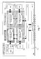
- FIG. 4is a diagram illustrating sets of Ingress Traffic Processors, Computation Processors, and Egress Traffic Processors used to implement aspects of the invention
- FIG. 5is a diagram of a feed-forward control loop illustrating aspects of the invention employed via bifurcation of packet flows;
- FIG. 6is a schematic diagram illustrating the communication interconnected between a Traffic Blade and a Compute Blade
- FIG. 7is a schematic diagram illustrating of one embodiment of a Compute Blade that is provisioned for an OAMP function
- FIG. 8is a schematic diagram illustrating one embodiment of a Traffic Blade
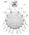
- FIG. 9is a schematic diagram illustrating one configuration of a service node implemented via a ATCA chassis
- FIG. 10is a schematic diagram illustrating details of the inter-blade communication scheme; according to one embodiment of the invention.
- FIG. 11is a schematic diagram illustrating a service node implementation environment including a local instance of a global arbitrator on each blade;
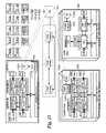
- FIG. 12is a schematic diagram illustrating various components associated with a Service Management Engine (SME);
- SMEService Management Engine
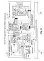
- FIG. 13is a schematic diagram illustrating details of the Bandwidth Management Component of the SME components of FIG. 12 ;
- FIG. 14is a schematic diagram illustrating details of the Services Management Component of the SME components of FIG. 12 ;
- FIG. 15is a schematic diagram illustrating details of the Application Scripting Component of the SME components of FIG. 12 ;
- FIG. 16is a flowchart illustrating operations employed to provision compute resources for an associated subscriber flow
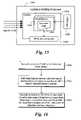
- FIG. 17is a schematic diagram of an exemplary execution environment for a service node used in connection with the packet processing operations of FIG. 18 ;
- FIG. 18is a flowchart illustrating operations performed in connection with processing a packet flow, according to one embodiment of the invention.
- Embodiments of methods and apparatus for optimum matching of traffic profiles with individual traffic flowsare set forth in order to provide a more thorough understanding of the invention. It will be appreciated, however, by one skilled in the art that the invention may be practiced without such specific details. In other instances, control structures, gate level circuits and full software instruction sequences have not been shown in detail in order not to obscure the invention. Those of ordinary skill in the art, with the included descriptions, will be able to implement appropriate functionality without undue experimentation.
- references in the specification to “one embodiment”, “an embodiment”, “an example embodiment”, etc.,indicate that the embodiment described may include a particular feature, structure, or characteristic, but every embodiment may not necessarily include the particular feature, structure, or characteristic. Moreover, such phrases are not necessarily referring to the same embodiment. Further, when a particular feature, structure, or characteristic is described in connection with an embodiment, it is submitted that it is within the knowledge of one skilled in the art to effect such feature, structure, or characteristic in connection with other embodiments whether or not explicitly described.
- Coupledmay mean that two or more elements are in direct physical or electrical contact. However, “coupled” may also mean that two or more elements are not in direct contact with each other, but yet still co-operate or interact with each other.
- FIGS. 5 , 16 , and 18Exemplary embodiments of the invention will now be described with reference to FIGS. 3-18 .
- the operations of the flow diagrams in FIGS. 5 , 16 , and 18will be described with reference to the exemplary architecture embodiments of FIGS. 4 , 6 - 15 , and 17 .
- the operations of these flow diagramscan be performed by embodiments of the invention other than those discussed with reference to FIGS. 4 , 6 - 15 , and 17 , and that the embodiments discussed with reference to FIGS. 5 , 16 , and 18 can perform operations different than those discussed with reference to these flow diagrams.
- FIG. 3illustrates an exemplary network configuration using a traffic shaping service node 302 in a metro area network according to one embodiment of the invention.
- traffic shaping service node 302is communicatively coupled between the core 102 and access 106 networks. While one embodiment is described under which the traffic shaping service node may shape traffic traveling in either direction, alternative embodiments may shape in only one direction (e.g., the service provider data traffic coming from the core network 102 .
- Traffic shapinga form of QoS, is the process of regulating and smoothing the flow of network data traffic within a computer network.
- Restricting the bandwidth of the traffic flowis one way to regulate data traffic.
- There are a variety of ways to bring data traffic flow with a desired rateincluding dropping or discarding data packets, buffering received data packets and re-transmitting the data packets at the desired rate, combinations of these (e.g., buffering packets when there is space in the buffer and dropping packets when there is not), etc.
- Buffering the data traffic flowallows the traffic shaping service node to smooth the data traffic flow. Smoothing removes the bursts of data traffic and shapes the data traffic into a constant flow of data traffic. Smoothing is advantageous for applications that depend on a constant flow of data traffic.
- the traffic shaping service node 302uses the subscriber policies contained in subscriber policy manager(s) 110 for instruction on how to shape the data traffic from service providers 104 A- 104 N and/or subscribers 108 A- 108 M accordingly. Further details of various elements of embodiments of traffic shaping service nodes are discussed below.
- techniquesare provided to enable optimum matching of a traffic profile with an individual traffic flow.
- This matching of the optimum traffic profileoccurs in real time without any static provisioning linking the flow with the profile.
- the matchingis achieved by the bifurcation and duplication of all packets (i.e., packet data) that make up a flow to a computation resource that will analyze the packets, maintain flow statistics, flow stateful information and classify the flow as a particular application traffic type.
- the optimum traffic profile for this application traffic typeis then selected and applied to the individual flow in real time.
- a Traffic Flowcomprises a set of packets having similar flow classification parameters.
- a typical ingress operation performed by a layer- 4 router or the likeis to classify received packets to associated flows using a rule-based packet classification scheme, such as defined by an Access Control List (ACL) database.
- ACLAccess Control List
- the rules for classifying a messagei.e., one or more associated packets
- filtersor rules in firewall terminology
- the packet classification problemis to determine the lowest cost matching filter or rule for each incoming message at the network element.
- the relevant informationis contained in N distinct header fields (or partial header fields) in each packet.
- the relevant fields for an IPv4 packetcomprise the Destination Address (32 bits), the Source Address (32 bits), the Destination Port (16 bits), the Source Port (16 bits), and the Protocol Field (8 bits); the set of field values for a given packet is referred to as the 5-Tuple signature.
- the corresponding filter databaseconsists of a finite set of filters, filt 1 , filt 2 . . . filt N .
- Each filteris a combination of N values, one for each header field.
- Each field in a filteris allowed three kinds of matches: exact match, prefix match, or range match and wildcard.
- exact matchthe header field of the packet should exactly match the filter field.
- prefix matchthe filter field should be a prefix of the header field.
- the header valuesshould like in the range specified by the filter.
- Each filter filt ihas an associated directive disp i , which specifies how to process a packet matching the filter.
- An Application Flowis a flow of packets that carries traffic belonging to a specific application, such as VoIP or VoD.
- the data carried in the packet headere.g., the 5-Tuple signature
- data in the packet payloadis employed for identifying the appropriate application.
- a technique known as Deep Packet Inspectionis required to further analyze the contents of the packet and to keep stateful context of previous packets seen in the flow.
- Modern network equipmentcan typically support 5-Tuple classification at line speed rates.
- classification schemes that employ deep packet inspectionmay not be implemented at line rate speeds in many instances.
- separate processing pathsrespectively referred to as fast path and slow path, are sometimes typically employed for performing 5-Tuple classification and deep packet inspection on a given network device.
- an apparatus via which the techniques may be implementedincludes various processor resources, including multiple ingress traffic processors 400 (depicted as i ingress traffic processors 400 1-i ), computation processors 402 (depicted as j computation processors 402 1-j ), and egress traffic processors 404 (depicted as k egress traffic processors 402 1-k ).
- ingress traffic processors 400depicted as i ingress traffic processors 400 1-i
- computation processors 402depicted as j computation processors 402 1-j
- egress traffic processors 404depicted as k egress traffic processors 402 1-k
- the particular values for i, j, and kmay be the same or may differ, depending on the particular implementation environment and requirements.
- the various ingress traffic processors 400 1-i , computation processors 402 1-j , and egress traffic processors 402 1-kare interconnected in a mesh fashion such that any processor may communicate with any other processor.
- the communication rates amongst the various processorsare equal. In other embodiments, the communication rates may differ.
- the traffic processorsperform 5-Tuple classification of flows, while the computation processors perform deep packet inspection of the flows and maintain stateful analysis data pertaining to each flow.
- an Ingress Traffic Processoris termed TP i
- an Egress Traffic Processoris termed TP e
- the ingress flowis termed F i
- the egress flowis termed F e .
- Packetsenter the apparatus at the TP i .
- the TP iidentifies a new incoming flow and make a routing decision R (F i ) regarding the destination TP e . Packets from the identified flow shall henceforth be sent to the TP e and exit the apparatus; packets thus flow from TP i to TP e .
- F iis bifurcated, and its packets duplicated, to provide an equivalent and simultaneous flow that is sent to one of the many Computation Processors (CP); which CP is selected is decided programmatically and is a function S (F i ) of the flow F i , as schematically depicted by the feed forward control loop of FIG. 5 .
- the bifurcated flowis termed F b .
- the CPshall be notified of the creation of a new flow, along with the 5-Tuple that accompanies the flow and it shall expect reception of the flow F b .
- the CPshall route the F b to specific software Analysis Entities that are capable of analyzing a traffic flow associated with the specific 5-Tuple.
- This routing to specific analysis entitiesenables any state or analytical information that has been extracted from the flow to be preserved, meaning that the analysis process has access to past state information and can alter its analysis based upon this information.
- the packet flowis bifurcated and duplicated, no additional latency or jitter is introduced into any traffic flow F i and F e .
- the result R b of the analysis performed in the CPis then passed onto the TP e and back to the TP i ; this enables the TP e to adjust the shaping performed on F e and allow the TP i to adjust the policing performed on F i .
- the Analysis Engineshall be working on packet P t producing a result R (P t ) that is sent to TP e .
- the arrival of the result R (P t ) at the TP ewill have a certain time delay introduced in relation to the packet P t that arrived at TP e as part of the original (non bifurcated) flow F e such that, as R (P t ) arrives at TP e , then the current packet being processed by TP e shall be P t+ ⁇ .
- the apparatushas the ability to view traffic in terms of Traffic Aggregates. Having access to these Traffic Aggregates and the statistics associated with then allow the Analysis Engines to select a traffic profile different from that which would result from isolated analysis of the traffic flow.
- services provided over the networkwill consist of multiple flows, each with their own 5-Tuple signature.
- the Analysis Enginesshall have the ability to draw together and group the information regarding these multiple flows and treat the grouping as a Service Flow.
- the Analysis Engineshave the ability to track the state of a Service Flow and dynamically alter the results being sent to the TP i and TP e that servicing the flows the make up the Service Flow.
- FIGS. 4 , 6 - 15 , and 17illustrate exemplary network element architectures that may be used for a variety of purposes, including but not limited to, a traffic shaping service node as previously described.
- a traffic shaping service nodeas previously described.
- FIGS. 4 , 6 - 15 , and 17are described with reference to a traffic shaping service node, it should be understood that these architectures are independent as part of the invention.
- the aforementioned functionsare facilitated by various processing and storage resources hosted by associated line cards and the like, which are mounted in a common chassis.
- the hardware architecture of one embodiment of a Service Nodecan be decomposed into three entities, Traffic Blades (TB) 600 , Compute Blades (CB) 602 and the chassis 604 .
- a TB 600can be further reduced to its physical and link layer portions 606 and 608 , network layer components 610 , and infrastructure components 612 .
- a CB 602provides Service Layer termination 613 and infrastructure components 614 .
- a CBcan be further re-defined to be an OAMP Blade based on its slot index (within chassis 604 ).
- OAMP bladesare a functional superset of CBs, adding operations, administration, maintenance and provisioning functionality (collectively referred to as OAMP card function or OAMP CF).
- chassis 604comprises an Advanced Telecommunication and Computing Architecture (ATCA or AdvancedTCA®) chassis.
- ATCA Chassisprovides physical connectivity between the blades via a passive backplane 616 including a full-mesh backplane 616 .
- a passive backplane 616including a full-mesh backplane 616 .
- the ATCA environment depicted hereinis merely illustrative of one modular board environment in which the principles and teachings of the embodiments of the invention described herein may be applied. In general, similar configurations may be deployed for other standardized and proprietary board environments, including but not limited to blade server environments.
- the ATCA 3.0 base specification(approved Dec. 30, 2002), which is being carried out by the PCI Industrial Computer Manufacturers Group (PICMG), defines the physical and electrical characteristics of an off-the-shelf, modular chassis based on switch fabric connections between hot-swappable blades. (As used herein, the terms “board,” “blade,” and “card,” are interchangeable.)
- This specificationdefines the frame (rack) and shelf (chassis) form factors, core backplane fabric connectivity, power, cooling, management interfaces, and the electromechanical specification of the ATCA-compliant boards.
- the electromechanical specificationis based on the existing IEC60297 EuroCard form factor, and enables equipment from different vendors to be incorporated in a modular fashion with guaranteed interoperability.
- the ATCA 3.0 base specificationalso defines a power budget of 200 Watts (W) per board, enabling high performance servers with multi-processor architectures and multi gigabytes of on-board memory.
- I/Oinput/output
- Advanced Switching (AS)employs a serial communication channel operating at Gigahertz+ frequencies.
- ATCA boardsmay also provide one or more I/O ports on their front panels, enabling an ATCA board to be coupled to other network resources.
- FIG. 7An exemplary architecture 700 for a compute blade 602 is shown in FIG. 7 .
- a single compute blade (physical) architectureis employed for both Compute Blades and OAMP CF's. More particularly, under architecture 700 , a corresponding blade may be deployed to support both Compute Blade and OAMP functionality.
- Compute Blade 602employs four multiple processor compute nodes 702 1-4 .
- each of compute nodes 702 1-4functions as multiple processor resources, with each processor resource being associated with a logical processor. Accordingly, such processor resources may be implemented using separate processors, or processor chips employing multiple processor cores.
- each of compute nodes 702 1-4is implemented via an associated symmetric multi-core processor. Exemplary multi-core processors that may be implemented include, but are not limited to Broadcom 1480 and 1280 devices.
- Each of the compute nodes 702 1-4is enabled to communicate with other compute nodes via an appropriate interface (e.g., bus or serial-based interfaces). For the Broadcom 1480 and 1280 devices, this interface comprises a “Hyper Transport” (HT) interface. Other native (standard or proprietary) interfaces between processors may also be employed.
- HTHyper Transport
- each compute nodes 702 1-4is allocated various memory resources, including respective RAM 704 1-4 .
- each of compute nodes 702 1-4may also be allocated an external cache 706 1-4 , or may provide one or more levels of cache on-chip.
- the RAMcomprises ECC (Error Correction Code) RAM.
- each compute nodeemploys a NUMA (Non-Uniform Memory Access) cache coherency scheme.
- NUMANon-Uniform Memory Access
- Other cache coherency schemessuch as MESI (Modified, Exclusive, Shared, Invalidated), may also be implemented for other embodiments.
- Each Compute Blade 602includes a means for interfacing with ATCA mesh interconnect 618 . In the illustrated embodiment of FIG. 7 , this is facilitated by a Backplane Fabric Switch 708 . Meanwhile, a field programmable gate array (FPGA) 710 containing appropriate programmed logic is used as an intermediary component to enable each of compute nodes 702 1-4 to access backplane fabric switch 708 using native interfaces for each of the compute nodes and the fabric switch.
- the interface between each of compute nodes 702 1-4 and the FPGA 710comprises an SPI (System Packet Interface) 4.2 interface, while the interface between the FPGA and backplane fabric switch 708 comprises a Broadcom HiGigTM interface. It is noted that these interfaces are merely exemplary, and that other interface may be employed depending on the native interfaces of the various blade components.
- the compute node associated with the OAMP function(depicted in FIG. 7 as Compute Node # 1 ) is provided with local SRAM 712 and a non-volatile store (depicted as Compact flash 714 ).
- the non-volatile storeis used to store persistent data used for the OAMP function, such as provisioning information and logs.
- each compute nodeis provided with local RAM and a local cache, as depicted in FIG. 11 .
- compute blade 602is provisioned as an OAMP blade.
- one of the compute nodesis employed for performing OAMP functions (e.g., compute node 702 1 ), while the other three compute nodes (e.g., compute nodes 702 2-4 ) perform normal compute functions associated with compute blades, as described in further detail below.
- compute nodes 702 1-4are available for performing the compute functions described herein.
- FIG. 8shows an exemplary architecture 800 for a traffic blade 600 .
- Architecture 800includes a PHY block 802 , an Ethernet MAC block 804 , a network processor unit (NPU) 806 , a host processor 808 , a SERDES interface 810 , an FPGA 812 , a backplane fabric switch 814 , RAM 816 and 818 and cache 819 .
- the traffic bladefurther includes one or more I/O ports 820 , which are operatively coupled to PHY block 820 .
- the number of I/O portsmay vary from 1 to N ports. For example, under one traffic blade type a 10 ⁇ 1 Gigabit Ethernet (GigE) port configuration is provided, while for another type a 1 ⁇ 10 GigE port configuration is provided. Other port number and speed combinations may also be employed.
- GigEGigabit Ethernet
- PHY block 802 and Ethernet MAC block 804respectively perform layer 1 (Physical) and layer 2 (Data Link) functions, which are well-known in the art.
- layer 1Physical
- layer 2Data Link
- the PHY and Ethernet MAC functionsmay be implemented in hardware via separate components or a single component, or may be implemented in a combination of hardware and software via an embedded processor or the like.
- One of the operations performed by a traffic bladeis packet identification/classification.
- a multi-level classification hierarchy schemeis implemented for this purpose.
- a first level of classificationsuch as the aforementioned 5-Tuple signature classification scheme, is performed by the traffic blade's NPU 806 .
- Additional classification operations in the classification hierarchythat may be required to fully classify a packet (e.g., identify an application flow type) in the manner discussed above.
- these higher-level classification operationsmay be performed by the traffic blade's host processor 808 and/or a processor on a compute blade, depending on the particular classification.
- NPU 806includes various interfaces for communicating with other board components. These include an Ethernet MAC interface, a memory controller (not shown) to access RAM 816 , Ethernet and PCI interfaces to communicate with host processor 808 , and an XGMII interface.
- SERDES interface 810provides the interface between XGMII interface signals and HiGig signals, thus enabling NPU 806 to communicate with backplane fabric switch 814 .
- NPU 806may also provide additional interfaces to interface with other components, such as an SRAM (Static Random Access Memory) interface unit to interface with off-chip SRAM (both not shown).
- SRAMStatic Random Access Memory
- host processor 808includes various interfaces for communicating with other board components. These include the aforementioned Ethernet and PCI interfaces to communicate with NPU 806 , a memory controller (on-chip or off-chip—not shown) to access RAM 818 , and a pair of SPI 4.2 interfaces. FPGA 812 is employed to as an interface between the SPI 4.2 interface signals and the HiGig interface signals.
- NPUsare designed for performing particular tasks in a very efficient manner. These tasks include packet forwarding and packet classification, among other tasks related to packet processing.
- NPU 806executes corresponding NPU software 822 .
- This softwareis shown in dashed outline to indicate that the software may be stored (persist) on a given traffic blade (e.g., in a flash device or the like), or may be downloaded from an external (to the traffic blade) store during initialization operations, as described below.
- NPU software 822is loaded into internal SRAM 823 provided by NPU 806 .
- Host processor 808is employed for various purposes, including lower-level (in the hierarchy) packet classification, gathering and correlation of flow statistics, and application of traffic profiles. Host processor 808 may also be employed for other purposes. In general, host processor 808 will comprise a general-purpose processor or the like, and may include one or more compute cores (as illustrated, in one embodiment a two-core processor is used). As with NPU 806 , the functionality performed by host processor is effected via execution of corresponding software (e.g., machine code and or virtual machine byte code), which is depicted as host software 824 . As before, this software may already reside on a traffic blade, or be loaded during blade initialization.
- corresponding softwaree.g., machine code and or virtual machine byte code
- host processor 808is responsible for initializing and configuring NPU 806 .
- host processor 808performs network booting via the DHCP (or BOOTP) protocol.
- DHCPor BOOTP
- an operating systemis loaded into RAM 818 and is booted.
- the host processorthen configures and initializes NPU 806 via the PCI interface.
- NPU 806may execute NPU software 822 on a run-time basis, without the need or use of an operating system.
- FIG. 9is a schematic diagram illustrating the cross-connectivity provided by the ATCA backplane mesh interconnect used in one embodiment of the Service Node.
- an ATCA chassis 604is fully populated with 14 ATCA blades, with each blade installed in a respective chassis slot—in an actual implementation, the chassis may be populated with less blades or may include other types of blades in addition to compute and traffic blades.
- the illustrated configurationincludes four compute blades 602 1-4 , and 10 traffic blades 600 1-10 , with one of the compute blades being provisioned to provide OAMP functions.
- each bladeis communicatively-coupled with every other blade under the control of fabric switching operations performed by each blade's fabric switch.
- mesh interconnect 618provides a 10 Gbps connection between each pair of blades, with an aggregate bandwidth of 280 Gbps.
- Inter-slot connectivityis enabled through a full mesh interconnect network compromising the ATCA passive backplane and a multi-port 10 Gbps switch fabric device integrated on every blade.
- a 16-port 10 Gbps HiGig switch(Broadcom proposed model BCM56700) is implemented for each of backplane fabric switches 708 and 814 .
- a pair of 8-port switch fabric devices(e.g., Broadcom BCM5675) may be employed in place of the 16-port device shown in FIG. 10 .
- Each fabric switch devicemaintains chassis facing ports and local facing HiGig ports.
- Each Traffic Blade 602 fabricpresent three local facing ports, while each Compute Blade 600 fabric present two local facing ports, with one spare port. The remaining ports are coupled to the backplane mesh, and provide support for a full 14-slot ATCA configuration
- the switch fabricis a distributed shared memory switch architecture with output port buffering.
- the fabricis implemented as an insertion ring.
- Each portprovides 128 K bytes of egress packet buffering (principal queue point) and 19 K bytes on ingress packet buffering (sufficient for address resolution and ring insertion delay) for a 9 K byte jumbo frame.
- the switch fabric architecture of FIG. 10utilizes the fabric to create a partial mesh. That is, full “any-to-any” port forwarding is not required. Specifically, the fabric only needs to forward from local to chassis facing ports (and vice versa) and forwarding between chassis facing ports is not required.
- the service nodeis implemented using a distributed architecture, wherein various processor and memory resources are distributed across multiple blades. To scale a system, one simply adds another blade. The system is further enabled to dynamically allocate processor tasks, and to automatically perform fail-over operations in response to a blade failure or the like. Furthermore, under an ATCA implementation, blades may be hot-swapped without taking the system down, thus supporting dynamic scaling.
- Yet another aspect of the inventionrelates to dynamic allocation of system resources, such as compute resources, queues, etc.
- compute resources and usageis monitored on an ongoing basis, and real-time statistics and the like are maintained using a distributed database scheme and a local (to each blade) agent, such that each blade has a “global” view of the entire system resource availability and consumption.
- FIG. 11shows an OAMP Blade 601 , multiple Compute Blades 602 , and multiple Traffic Blades 600 .
- Each of these bladesruns an instance of a software agent or the like (e.g., service, daemon, etc.) referred to as the “Global Arbitrator” 1100 .
- one of the compute nodes on a Compute Bladewill be provisioned to run a Global Arbitrator, while the host processor on a Traffic Blade will be used for a similar function.
- Each of the Global Arbitrator instancesare enabled to communicate with one another using a common protocol running over the aforementioned communication signal infrastructure. For example, in one embodiment, Global Arbitrators exchange IP packets to communicate with one another. Other protocols may be implemented in a similar manner.
- the Global Arbitrators 1100are used to perform various tasks. Some task examples include: Distributed Scheduling, Process Management, Group Management, Inter-Process Communication (IPC), and Remote Procedure Calls (RPC). With respect to Distributed Scheduling and Process Management, each Global Arbitrator will maintain local and global resource information for the system. In this case, each Distributed Schedule module for each Global Arbitrator instance will identify the resources on its host blade (e.g., disk, memory, processing, networking, and subscribers), and then propagate this information to the other Global Arbitrators, as illustrated in FIG. 11 . The Distributed Schedulers will also be responsible for load balancing resources across blades by tracking local resource loading an propagating this information to other Distributed Schedulers, such that each Global Arbitrator have access to a “world view” of available resources and resource consumption.
- IPCInter-Process Communication
- RPCRemote Procedure Calls
- the Global Arbitratorswill maintain a distributed database 1102 having a local instance 1102 A stored on each blade.
- the distributed database 1102which functions as a virtual database, will be maintained in such a manner that if a blade fails, no information will be lost.
- Each local database instancewill store both local and global data.
- subscribersare associated with groups (based on their Subscriber Profile, such as QoS requirements and other contracted service parameters), while groups, in turn, are associated with resource groups.
- groupsmay be associated with resources on a blade basis (e.g., Group 1 is associated with Traffic Blades 1, 2, 6, and 7 or with further granularity, such as the individual resource level (e.g., each compute node comprises an individual resource that may be allocated to a given group).
- One of the purposes of the Group-to-subscriber mappingpertains to resource allocation.
- the systemwill attempt to maintain load balancing by allocating resources such that the resources are consumed at a similar level across the infrastructure.
- the subscriber-to-group allocationenables subscribers that have contracted for different levels of services to be allocated a corresponding level of (access to) resources. For example, some groups may be allocated more resources on a per-subscriber basis such that service flows corresponding to subscribers that have purchased a higher level of service will be allocated relatively more resources than service flows corresponding to lower QoS subscribers.
- SMEService Management Engine
- the SMEprovides key added value over and above that of a traditional network element such as a BRAS and Edge-Router.
- a traditional BRAS/Edge-Routeris able to manage subscribers' traffic on a per session basis.
- a service node, equipped with the SMEprovides visibility into subscriber sessions, and enable traffic management on a per application level. In addition, it is able to provide customized, network-based, and subscriber-aware application services.
- the SMEprovides these functionalities through flow classification, deep packet inspection, flow level traffic management, and application service scripting.
- subscriber trafficenters a service node, it is separated into flows.
- the flowsare classified by their application-level protocols with the aid of deep packet inspection.
- Some of these flowsare traffic-managed according to the authorization of the subscriber to which they belong. This management typically includes policing, shaping and prioritization on a per flow basis.
- Other flowsare bifurcated or diverted to application service scripts that implement various customized services.
- the SMEbuilds on the subscriber management functions of a BRAS, and extends traffic management to a per-subscriber/per-application level. It also exposes some of these functions in a generic state machine so that customized applications may be built on top of these.
- the service management engine softwareis the top most functional layer in the system. It uses features provided by the lower layers; it guarantees certain level of quality of service for services and applications under management; and it provides visibility into the traffic stream for the network operators.
- the Service Management Engineis the runtime layer of Services Management Software Environment. It may be divided into three major functional areas: Bandwidth Management, Service Management, and Application Scripting.
- the Bandwidth Management areais concerned with per-subscriber/per-service traffic management; the Service Management area is concerned with classifying flows and following protocol negotiations; and the Application Scripting area is concerned with providing capability to script custom network-based application services.
- FIG. 12shows the major components of the SME, and their interactions. Some components are shown in more detail, while external components such as subscriber management, traffic management, and the global arbitrator are not shown for clarity. FIG. 12 also does not show the internal layering of the components.
- the SMEconsists of three major abstract components: Bandwidth Management component (BMC) 1201 , a Services Management component (SMC) 1202 , and an Application Scripting Component (ASC) 1204 .
- BMC 1201is responsible for tracking per-subscriber usage statistic and traffic authorization and admission.
- SMC 1202is responsible for classification of flows, dissection of packets, and correlation of flows to services.
- ASC 1204runs sandboxes in which scripts may be executed.
- the Bandwidth Management Component 1201depends on a Subscriber Management Subsystem (SMS) (which provides subscriber information 1206 ), a Statistics Engine 1208 , as well as a Traffic Management Engine (TME) 1210 for operation.
- SMSSubscriber Management Subsystem
- Statistics Engine 1208receives correlated traffic and flow statistics on a per-subscriber and per-port/circuit basis from Statistics Engine 1208 . It runs a per-subscriber state machine that keeps track of subscriber authorization, bandwidth consumption, and service utilization. It also receives service classification information from Service Management Component 1202 , and computes traffic management policies on a per-flow basis. These policies are then sent to the TME 1210 for execution.
- BMC 1201includes a Bandwidth Controller 1212 , and a Traffic Monitor 1214
- the Services Management Component 1202supplies the protocol and service classification information to Bandwidth Management Component 1201 . It receives pre-classified packet flows that are bifurcated from the ingress traffic blade; it classifies each flow by their application level protocol; it dissects packets from interested flows in order to get application level messages; finally, it correlates flows to services, and sends the service classification and traffic specification of flows to BMC and other interested listeners. These operations are facilitated by a Flow Classifier 1216 and a Service Classifier 1218 .
- the Application Scripting Component 1204implements a sandbox where “application scripts” may be executed in virtual machines. This component provides an API and an execution environment similar to what is available to the Bandwidth Management Component. In addition, Service Definition Scripts may direct specific messages to a particular application script. Application Scripts may implement custom application state machines, or security and traffic management policies. Each script has its dedicated environment.
- each subscriberis provisioned with a list of services; and each service is tagged with a service class: Best Effort, Managed, or Preferred.
- service classBest Effort, Managed, or Preferred.
- Profiles of servicesare provisioned at the management layer of SMC 1202 . They are provisioned in the form of Service Definition Scripts.
- a Service Definitionspecifies what protocols a service uses, how a service is matched, what values are expected in the service's control protocol negotiations, the traffic profile of the data streams, and the control actions to be taken when this services is detected.
- These profilesare stored in a service node's persistent file system. The SMC uses these profiles to match flows to services, and obtain their traffic profiles, which are delivered to the BMC 1201 .
- Application Scriptsare provisioned at the management layer of ASC 1204 . They are stored in a service node's persistent file system, and are loaded into their sandboxes at startup time.
- the Service Node platform architectureemploys a substantial level of parallelism, as provided by multiple Compute and Traffic Blades.
- External entitiessuch as subscriber provisioning and AAA (Authentication, Authorization, and Accounting), the Statistics Engine 1208 , and the Traffic Management Engine 1210 are run in their own processes.
- the SMEspreads itself along component boundaries.
- the Bandwidth Management Componentwill have its own process; so is the Service Management Component.
- the Application Scripting componentwill have a sandbox process from which all application scripts run.
- Each compute-node that is not reserved for OAMP functionswill have a full set of SME processes, including one BMC process, one SMC process, and one ASC process. Each of these processes is also multithreaded as described below.
- a compute-nodeis responsible for a number of subscribers. All processing, analysis and computation done for, or on behalf of, these subscribers are conducted on this compute-node.
- the Global Arbitrator 1100has the responsibility to allocate subscribers to compute-nodes when they are authenticated.
- the Service Management Componentoffloads some of its tasks, such as IP reassembly and preliminary classification, to a process on the host processor on Traffic Blades 600 . This process may run these tasks directly, or act as a proxy for the ASIC/FPGA array.
- SMEhas a configuration management (CM) process that implements the management layer functions.
- CMconfiguration management
- each of BMC 1201 and SMC 1202employ several threads that drain their work queues.
- the BMCemploys two or more “worker threads”, each of which is responsible for a (disjoint) subset of subscribers that are assigned to a particular BMC instance.
- the IPC servicing thread of a BMCwill sort messages for different subscribers into different work queues based on their subscriber identification.
- the SMCemploys two or more threads that process incoming packets. The division of labor between threads is defined on a per-flow basis.
- the specific number of worker threads per processwill be decided based on processor utilization data after profiling the processes with experimental data load.
- the ASCemploys one master thread, and at least one worker threads per application script.
- the ASC virtual machineshave facilities to allow application scripts to spawn more threads when desired.
- the SMCreceives pre-classified datagrams from the packet processing HAL 1220 ; these datagrams are packed in IPC messages with extra headers.
- the worker threads of SMC 1202will run flow classifiers, packet dissectors, as well as service classifiers on these messages and, in turn, produce “application level messages” for those services identified. These messages are then delivered to BMC 1201 .
- the BMC's worker threadsare driven with these messages; they produce traffic management directives for Traffic Management Engine 1210 .
- the ASC 1204 worker threadsare driven, similarly, with messages from SMC 1202 and other parts of the system.
- subscriber authorizationis provisioned in the Subscriber Management Subsystem. This information is provisioned statically, either on the node or in an external database. It is retrieved when a subscriber authenticates; and it is made available to the rest of the system software through sharing of the embedded provisioning information database.
- Each subscriber's authorization dataincludes a list of names of services, as well as their access class, namely “guaranteed”, “managed” or “best effort” in one embodiment.
- each compute-node that does not serve the OAMP functionwill have an instance of SME with all of its components.
- Each instanceis responsible for a number of subscribers.
- the list of subscribers served by a particular compute-node, or SME instance,is decided by the Global Arbitrator 1100 when subscribers authenticate. The decision is based on available compute resources on all available compute-nodes.
- the protocol descriptionsare provisioned as binary loadable modules that are loaded into SMC 1202 .
- the SMChas descriptions of a number of protocols built-in, while descriptions of extra protocols are loaded as protocol dissector plug-in modules.
- all protocol definitionsincluding the provisioned ones, are loaded automatically. These definitions may be de-provisioned by user request, provided that no other protocol or service definitions depend on them.
- the service definitionsare provisioned as clear text scripts. These definitions are provisioned at the management layer of SMC 1202 , and saved in a persistent file system. Each SMC instance loads the complete list of provisioned service definitions when it starts. These definitions may be de-provisioned at any time.
- application scriptsare provisioned at the management layer of ASC 1204 and stored in the persistent file system.
- the scriptsare loaded into the ASC process by the master thread on each compute-node when the embedded software for that node is started. They may be de-provisioned and unloaded at any time.
- the SMEprovisions the Traffic Management Engine dynamically.
- the SMEspecifically the BMC, computes traffic management policies on the fly based on subscribers' authorization and real-time traffic condition. These policies are sent to the TMC for enforcement
- One “application” provided by the SMEis bandwidth management. This is performed by assigning classes of service to flows based on their classification and the authorization of the subscriber to whom they belong.
- the SMErelies on Subscriber Management Subsystem 1206 for subscriber authorization information, on Statistics Engine 1208 for circuit and flow level statistics, and on Traffic Management Engine 1210 for traffic management policy enforcement.
- a BMCemploys a Traffic Monitor 1214 and a Traffic Controller 1212 .
- the Traffic Monitorinterfaces with Statistics Engine 1208 to monitor network traffic.
- the Traffic Monitoraggregates traffic statistics on a per-port or per-circuit basis. On subscriber facing interfaces, however, the Traffic Monitor aggregates statistics on per-destination or per-subscriber basis.
- Core-side monitoringprovides information for admission control when new service is initiated. Subscriber-side monitoring helps to determine how much bandwidth and throughput any given subscriber is using. Together with their allotted bandwidth and throughput authorization, this information is taken as an input for deciding the class of service a new flow receives.
- flow-based statistics on selected flowsare monitored for verifying the QoS a particular flow experiences.
- the Traffic Controller 1212computes traffic management policies on a per flow basis. It runs a “traffic state tracking machine” for each subscriber under its management. It has access to subscriber authorization information, including service profiles, and provisioned bandwidth and throughput. It receives classification and traffic profile information for detected or expected flows of recognized network applications (services) from Service Management Component 1202 . It then validates whether there is enough bandwidth on the subscriber's line to accommodate it.
- the Traffic Controller's primary focusis to decide the class of service for a given flow and a given subscriber. If a flow is of a guaranteed service, and there is enough bandwidth, given the flow's traffic profile and the available bandwidth of the subscriber's line, then the flow will be admitted to the guaranteed class. Queues for other classes of traffic are adjusted, as necessary, to accommodate this flow. Otherwise, the flow will be added to the best-effort class. An alarm indication may be raised in this situation. Regardless of service classes, policing, shaping, and priority parameters are setup for all flows to protect them from each other, and to protect service level agreements for all subscribers.
- the Services Management Component 1202is responsible for identifying and monitoring services. As shown in FIGS. 12 and 14 , the SMC receives bifurcated flows of packets from the Packet Processing HAL (Hardware Abstraction Layer) 1220 (PPHAL), classifies the flows according to the protocol they use, dissects the packets into application level messages, and matches flows to known “services”. Once a service is identified, SMC 1202 sends a notification with flow identification and classification information, as well as traffic profile to the BMC instance on the same compute-node. This notification may include a Flow Information Record (FIR) that contains various flow statistics.
- FIRFlow Information Record
- no traffic(for an associated flow) is bifurcated.
- a subscriberWhen a subscriber is authenticated and assigned to a compute-node, its authorization list is analyzed at the BMC instance on that node. If the subscriber subscribes to any service that is being supported, the BMC instance will contact the SMC instance on the same compute-node, which, in turn, will instruct PPHAL 1220 to bifurcate traffic belonging to this subscriber to this node. If a subscriber is not authorized to use any “service,” then no bifurcation is needed. For authorized subscribers, SMC 1202 will attempt to classify as much traffic as possible, and discard packets that it can not process.
- SMC 1202will determine whether it needs to receive more packets from this flow. It is expected that only control flows need constant monitoring in SMC. High bandwidth flows, such as media flows, only need to be classified and never looked at again.
- the Services Management Componentcan be broken down to two parts: the Flow Classifier 1216 and the Service Classifier 1218 .
- the Flow Classifieras its name suggests, is responsible for classification of packet flows. It runs a set of Packet Dissection Plug-in modules (Packet Dissectors).
- Packet DissectorsPacket Dissectors
- a Pre-Classifier in PPHAL 1220filters out flows that are not of interest to the SMC, and only bifurcate flows belonging to subscribers who are assigned to a particular instance of SMC to that instance of SMC.
- the SMCis responsible to provision classification rules to the PPHAL so that only flows that are potentially interesting are bifurcated; the BMC, however, is responsible for notifying the SMC, which, in turn, registers with PPHAL of subscribers that are to be monitored by a particular instance of SMC.
- the Service ClassifierFor every packet it encounters, the Service Classifier performs deep packet inspection by running through its protocol dissectors 1400 . Each protocol dissector assigns a percentage probability of a packet being of its associated protocol. At the end, the protocol with the highest probability wins. Some flows, however, may not be classified successfully: all dissectors may report very low probability. Accordingly, unclassified flows will be lumped into an “unclassified” pool. For management purposes, they will only be distinguishable by their flow ID. The classified flows are dissected into application level messages and passed to Service Classifier 1218 for further analysis.
- the Service Classifiercorrelates classified and dissected packet flows as services. Services are defined by Service Definitions 1402 .
- a Service Definitiondescribes how a service is recognized, its traffic profile, and what actions to take when such a service is detected.
- Service Classifier 1218reads in all available service definitions at startup time, and builds an internal data structure for service classification. Additional service definitions may be loaded at runtime. When service definitions are added or removed, this internal data structure is amended dynamically.
- a service definitionmay request the traffic profile and the flow information record be sent to other components including, but not limited to, BMC 1201 .
- a service definitionmay be used, for example, to send information to Application Scripts running in a sandbox.
- the Service Management Componentmaintains one FIR for each flow it monitors. Protocol classification and service classification results are recorded in these Flow Information records. FIRs are used when communicating classification information with other components.
- the SMC 1202relies on PPHAL 1220 to deliver bifurcated flows of packets to the correct instance of the software. As discussed earlier, when a subscriber is authenticated, it is assigned to a particular compute-node, and a particular instance of the SMC software. In addition, a backup instance may be specified at the same time by Global Arbitrator 1100 . This assignment is communicated to PPHAL 1220 , and it is the responsibility of the PPHAL to deliver bifurcated packets to the correct instance of the software. Moreover, SMC 1202 will instruct PPHAL 1220 to stop bifurcation of certain flows when enough information has been obtained from packet inspection.
- the main communication method for delivering bifurcated packets from PPHAL 1220 to SMC 1202will be IPC, using the “push” model.
- the communication channel from SMC 1202 to PPHAL 1220 for control messagingwill use RPC (Remote Procedure Call).
- the primary client of SMC 1202is the Bandwidth Management Component 1201 .
- a BMC instancenotifies the SMC instance on the same compute-node the set of subscribers who are under its management.
- the SMC instanceregisters with PPHAL 1220 to receive bifurcated packets from these subscribers.
- PPHAL 1220registers with PPHAL 1220 to receive bifurcated packets from these subscribers.
- SMC 1202sends the classification result and traffic profile to BMC 1201 for policy decision rendering.
- the API from BMC to SMCcomprises an RPC interface; whereas the interface from SMC to BMC will use IPC. As there is no shared data, no locking is necessary.
- the Application Scripting Component 1204is client of SMC 1202 , and is very similar to BMC 1201 .
- the ASCreceives copies of IPC events that are sent to BMC 1201 . However, it does not provision SMC 1202 as does BMC 1201 .
- SMC 1202couples with a configuration manager (CM) in the Management Layer (not shown).
- CMconfiguration manager
- the configuration managerresides on a compute-node that is dedicated for OAMP functions. They communicate via the provisioning database. While the configuration manager has write access to the provisioning information database, SMC only has read access. Multiple instances of SMC may share read locks on the same record set in this database.
- the Application Scripting Component 1204implements a sandbox where “application scripts” may be executed in virtual machines.
- the ASCprovides an API and an execution environment similar to what is available to BMC 1201
- Service Definition Scriptsmay direct specific messages to a particular application script.
- Application Scriptsmay implement custom application state machines or security and traffic management policies. Each script has its dedicated environment. This is where network-based applications can be hosted on the service node.
- VMM 1500is responsible for setting up the sandbox, and starting all virtual machines that run application scripts. For every application script, a separate virtual machine 1504 is started. The VMM monitors virtual machines that it starts, and restarts them if they crash.
- Sandbox 1502an execution environment for generic state machine engines (see FIG. 12 ) (or virtual machines) which, in turn, run Application Scripts 1506 .
- the sandboxdelivers events from other parts of the system to the virtual machines; in addition, it provides guarded access to a selected API 1508 for access resources and runtime information available on the network element.
- the virtual machinescomprise generic state machine engines. In respective embodiments they may be implemented as Mono or Java virtual machines with specific class libraries.
- the sandboxis built with a Common Language Runtime (CLR) that is based on Mono with a custom-built Just-In-Time compiler to execute the Common Intermediate Language (CIL) byte code.
- CLRCommon Language Runtime
- CILCommon Intermediate Language
- the generic state machinesmay be implemented as “application domains” within the sandbox.
- class librariesprovide the event mechanism as well as API 1508 to the rest of the system.
- Application scriptshave access to flow information, statistics, as well as classification results from SMC 1202 . They may be granted other access to components such as Traffic Management and Subscriber Management, depending on their intended application.
- the Application Scripts 1506are in the form of CIL packages known as “assemblies.”
- An application service developermay use any language for which a compiler with a backend for generating CIL byte code is available.
- the preferred languageis C#.
- Each Application Script 1506is loaded into a separate application domain in the CLR.
- the Application Scriptshave access to system information and resources similar to those available to BMC 1201 ; however, they are not allowed to interact with each other for security reasons.
- the various resources that are employed for handling a given flowmay be (generally) located anywhere within the service node, thus supporting various capabilities, such as full scalability and failover.
- specific resourcesare assigned for handling particular flows based on the subscriber and possibly other considerations, such as application (e.g., VoIP, VoD, etc.).
- FIG. 16illustrates operations that are employed to provision a new flow.
- the processbegins in a block 1600 , wherein a subscriber attempts to obtain a IP address or initiates a PPOE Session.
- each ingress Traffic Bladeswill provide a set of one or more input ports via which input traffic is received by the service node, such that a particular flow received from a given subscriber will be received by a particular Traffic Blade.
- that Traffic Bladewill perform a preliminary inspection to identify the subscriber or subscriber session (e.g., a given subscriber may have multiple sessions open at the same time, including sessions having different applications).
- the Traffic Blade NPUwill have access to a distributed runtime database containing flow assignments based on some filtering criteria (e.g., 5-Tuple signature), whereby the NPU can determine the assignment for a flow using a database lookup. In the case of a new flow, this is result in a miss, and the NPU will forward the processing to the control plane and send the flow to an OAMP blade to verify and/or authenticate the subscriber.
- subscriber authenticationmay be performed using one of many well-known authentication schemes, such as an AAA server.
- the processmoves to a block 1604 , wherein the subscriber will be associated with an IP address or other Tuple, with the association being stored as a record in the runtime database.
- the global arbitratorassigns the subscriber to a compute node/blade based on a combination of criteria, including the group associated with the subscriber/application and dynamic considerations, such as discussed above (e.g., load balancing, etc.)
- the global arbitratorfurther informs the SME that the subscriber has been assigned to the compute node/blade and which Traffic Blade the subscriber has been activated on.
- FIG. 17an exemplary service node environment is shown in FIG. 17 .
- this environmentemploys a fully-populated ATCA chassis including 10 Traffic Blades 600 1-10 , and 4 Compute Blades 602 1-4 , with Compute Blade 602 , being provisioned as to support OAMP functions.
- Each of the Traffic and Compute Bladesare communicatively-coupled via mesh interconnect 618 , with access to the interconnect being managed by the backplane fabric switch on each blade.
- a global arbitrator 1100 instancewill run on each blade, as exemplified by OAMP blade 602 1 .
- OAMP blade 602 1For simplicity and clarity, other global arbitrators are not shown.
- various SME component instanceswill be run on the various blades.
- these SME component instancesare schematically depicted as SME instances 1200 1-3 . It will be understood that the actual SME component instances will include instances of SME components applicable to the respective execution host (i.e., each of the Traffic Blades 600 1-10 and Compute Blades 602 1-4 will run instances of associated SME components).
- FIGS. 5 , 17 , and 18the on-going flow operations begin at a block 1800 in FIG. 18 , wherein a packet (flow) is received at an ingress port.
- an ingress packet flow F i(depicted as packets P 1 and P 2 ) is received at an input port of an ingress Traffic Blade 6001 .
- ingress operations including primary classificationis performed by the Ingress Traffic Blade's NPU, which functions as an Ingress Traffic Processor TP i of FIG. 5 .
- TP ifunctions as an Ingress Traffic Processor
- Other classification schemesmay also be employed in a similar manner. The purpose of the classification is to associate the packets with a subscriber flow.
- subscriber informationis retrieved from a runtime database (e.g., Subscriber Management DB 1206 ) to identify the compute resources that will be employed to process the subscriber flow. As discussed above, this information (i.e., subscriber-to-resource mapping) is generated in block 1604 of FIG. 16 .
- the compute resourcecomprises Compute Node # 3 on compute blade 6002 .
- the Ingress Traffic Bladealso identifies the Egress Traffic Blade to which the packet is to be sent for Egress processing.
- thiscomprises Egress Traffic Blade 600 10 , which also functions as Egress Traffic Processor TP e of FIG. 5 .
- the processing of the packetis bifurcated.
- This aspectinvolves two primary operations: copy the packet to each target processor, and perform respective sets of packet processing operations on those target processors.
- the copy operationis accomplished in the following manner. First, the packet is copied from its NPU buffer (e.g., local RAM) into the backplane fabric switch 814 of Ingress Traffic Blade 600 1 . Along with copying the packet, information is provided to the backplane fabric switch to instruct the switch to which target blades the packet is to be copied to.
- NPU buffere.g., local RAM
- the backplane fabric switches 814 and 708implement a insertion ring scheme, under which certain cross-connections exist for each transmit “cycle.” A bit mask or the like is used to identify which blade(s) is/are targeted to receive a copy of the data, based on the slot address of the blade.
- the backplane fabric switch of a given bladedetermines if there is an interconnect from itself to the backplane fabric switch on another blade for which request for a data transfer is pending. If so, the data is transmitted during that cycle; otherwise the backplane fabric switch waits for the next cycle. Meanwhile, the data is held in a fabric switch buffer until all copies of the data have been transmitted.
- This schemeprovides several advantages over conventional copy schemes. Under a typical scheme, a processor or the like is employed for each copy. In addition, an interconnect path may not be immediately available, especially under a priority-based fabric switch scheme. Each of these may consume additional processor resources, which in turn may introduce jitter an/or delay. In contrast, under the insertion ring discussed herein, there is no jitter or delay introduced to the packet processing.
- the flow to the Egress Traffic Blade(the egress flow) is termed F e
- the bifurcated flow to the Compute Bladeis termed F b
- egress packet processing operationsare performed in a block 1808 . This typically involves assigning the packet to an associated flow queue and appending the packet to that flow queue.
- Other ongoing traffic management and shaping processesmay be employed for dispatching the flow queues for transmission to a next hop in the network, such as employed by round robin and priority-based dispatch schemes.
- the flow queue assignmentis based, in part, on current traffic profiles and subscriber flow attributes such as flow application. For example, in one embodiment flow queues are dispatched using a priority-based scheme, with flows associated with higher QoS, for example, receiving higher priority.
- the availability of queue dispatch (and corresponding queue assignments)may be managed in view of current traffic profiles. Accordingly, the assignment of a subscriber flow packet into a dispatch queue is a dynamic consideration that may change over time in view of changes in traffic profiles and the like.
- the Analysis Engine of FIG. 5is employed to perform analysis of the traffic flow in a block 1810 .
- the Analysis Engine functionsare effected via corresponding SME component instances in the manner described above and as represented by SME instance 1200 2 .
- the Analysis Enginegenerates traffic profile information that is provided to each of the Ingress and Egress Traffic Blades to update there traffic profile information.
- this resultcan be effected by updating a local instance of a distributed Traffic Profile (TP) database 1800 with the new traffic profile information.
- TPTraffic Profile
- the updated traffic profile informationis propagated to each local instance of the Traffic Profile database, thereby effectively providing the updated traffic profile information to Egress Traffic Blade 600 10 , as depicted by the update Traffic Profiles operation of block 1814 .
- the traffic analysis information generated in block 1810may be used to adjusting policing operations performed on the ingress flow, as shown in a block 1816 .
- Thisprovides a means by which an Ingress Traffic Blade can dynamically adjust its ingress processing operations for a given flow in view of real-time traffic analysis feedback derived from that flow.
- a machine-readable mediumincludes any mechanism for storing or transmitting information in a form readable by a machine (e.g., a computer).
- a machine-readable mediummay include a read only memory (ROM); a random access memory (RAM); a magnetic disk storage media; an optical storage media; and a flash memory device, etc.
- a machine-readable mediumcan include propagated signals such as electrical, optical, acoustical or other form of propagated signals (e.g., carrier waves, infrared signals, digital signals, etc.).
Landscapes
- Engineering & Computer Science (AREA)
- Computer Networks & Wireless Communication (AREA)
- Signal Processing (AREA)
- Data Exchanges In Wide-Area Networks (AREA)
Abstract
Description
PRfe(Pt+Δ)=R(Pt)where Δ→0 (1)
Claims (30)
Priority Applications (4)
| Application Number | Priority Date | Filing Date | Title |
|---|---|---|---|
| US11/224,201US7508764B2 (en) | 2005-09-12 | 2005-09-12 | Packet flow bifurcation and analysis |
| CA2620349ACA2620349C (en) | 2005-09-12 | 2006-08-30 | Packet flow bifurcation and analysis |
| EP06790602AEP1932312A4 (en) | 2005-09-12 | 2006-08-30 | BIFURCATION AND ANALYSIS OF DATA STREAMS PACKED BY PACKETS |
| PCT/CA2006/001423WO2007030917A1 (en) | 2005-09-12 | 2006-08-30 | Packet flow bifurcation and analysis |
Applications Claiming Priority (1)
| Application Number | Priority Date | Filing Date | Title |
|---|---|---|---|
| US11/224,201US7508764B2 (en) | 2005-09-12 | 2005-09-12 | Packet flow bifurcation and analysis |
Publications (2)
| Publication Number | Publication Date |
|---|---|
| US20070058632A1 US20070058632A1 (en) | 2007-03-15 |
| US7508764B2true US7508764B2 (en) | 2009-03-24 |
Family
ID=37855020
Family Applications (1)
| Application Number | Title | Priority Date | Filing Date |
|---|---|---|---|
| US11/224,201Active2027-03-25US7508764B2 (en) | 2005-09-12 | 2005-09-12 | Packet flow bifurcation and analysis |
Country Status (4)
| Country | Link |
|---|---|
| US (1) | US7508764B2 (en) |
| EP (1) | EP1932312A4 (en) |
| CA (1) | CA2620349C (en) |
| WO (1) | WO2007030917A1 (en) |
Cited By (39)
| Publication number | Priority date | Publication date | Assignee | Title |
|---|---|---|---|---|
| US20070058629A1 (en)* | 2005-09-09 | 2007-03-15 | Luft Siegfried J | Application driven fast unicast flow replication |
| US20070127483A1 (en)* | 2005-12-02 | 2007-06-07 | Alcatel | Network node with modular multi-stage packet classification |
| US20070208843A1 (en)* | 2006-03-06 | 2007-09-06 | B-Hive Networks, Inc. | Service Level Management System |
| US20070208852A1 (en)* | 2006-03-06 | 2007-09-06 | B-Hive Networks, Inc. | Network sniffer for performing service level management |
| US20080114892A1 (en)* | 2006-11-09 | 2008-05-15 | Aurelien Bruno | Method and apparatus for providing flow based load balancing |
| US20080151757A1 (en)* | 2006-12-26 | 2008-06-26 | Hitachi, Ltd. | Traffic information aggregating apparatus |
| US20080195731A1 (en)* | 2005-05-13 | 2008-08-14 | Gautier Harmel | Distributed Traffic Analysis |
| US20080311941A1 (en)* | 2007-06-13 | 2008-12-18 | Alvarion Ltd. | Method and devices for bandwidth allocation in a wireless communications system |
| US20090086651A1 (en)* | 2007-10-02 | 2009-04-02 | Luft Siegfried J | Intelligent collection and management of flow statistics |
| US20090116383A1 (en)* | 2007-11-02 | 2009-05-07 | Cisco Technology, Inc. | Providing Single Point-of-Presence Across Multiple Processors |
| US20090144414A1 (en)* | 2007-11-30 | 2009-06-04 | Joel Dolisy | Method for summarizing flow information from network devices |
| US20090141638A1 (en)* | 2007-11-30 | 2009-06-04 | Joel Dolisy | Method for partitioning network flows based on their time information |
| US20090144304A1 (en)* | 2007-11-30 | 2009-06-04 | Josh Stephens | Method for summarizing flow information of network devices |
| US20090252148A1 (en)* | 2008-04-03 | 2009-10-08 | Alcatel Lucent | Use of DPI to extract and forward application characteristics |
| US20090290501A1 (en)* | 2008-05-23 | 2009-11-26 | Levy Joseph H | Capture and regeneration of a network data using a virtual software switch |
| US20090292736A1 (en)* | 2008-05-23 | 2009-11-26 | Matthew Scott Wood | On demand network activity reporting through a dynamic file system and method |
| US20090316711A1 (en)* | 2008-06-24 | 2009-12-24 | Intel Corporation | Packet switching |
| US20100098086A1 (en)* | 2006-11-30 | 2010-04-22 | Kelly Donald Fromm | Preventing Forwarding of a Packet to a Control Plane |
| US20100180004A1 (en)* | 2009-01-12 | 2010-07-15 | Network Instruments, Llc | Apparatus and methods for network analysis |
| US7761485B2 (en) | 2006-10-25 | 2010-07-20 | Zeugma Systems Inc. | Distributed database |
| US20100195538A1 (en)* | 2009-02-04 | 2010-08-05 | Merkey Jeffrey V | Method and apparatus for network packet capture distributed storage system |
| US20100211668A1 (en)* | 2009-02-13 | 2010-08-19 | Alcatel-Lucent | Optimized mirror for p2p identification |
| US20110087771A1 (en)* | 2009-10-05 | 2011-04-14 | Vss Monitoring, Inc. | Method, apparatus and system for a layer of stacked network captured traffic distribution devices |
| US20110125748A1 (en)* | 2009-11-15 | 2011-05-26 | Solera Networks, Inc. | Method and Apparatus for Real Time Identification and Recording of Artifacts |
| US20110125749A1 (en)* | 2009-11-15 | 2011-05-26 | Solera Networks, Inc. | Method and Apparatus for Storing and Indexing High-Speed Network Traffic Data |
| US20110154449A1 (en)* | 2006-11-03 | 2011-06-23 | At&T Intellectual Property I, L.P. | System and Method of Multimedia Access |
| US20110158250A1 (en)* | 2009-12-30 | 2011-06-30 | International Business Machines Corporation | Assigning Work From Multiple Sources to Multiple Sinks Given Assignment Constraints |
| US20110158249A1 (en)* | 2009-12-30 | 2011-06-30 | International Business Machines Corporation | Assignment Constraint Matrix for Assigning Work From Multiple Sources to Multiple Sinks |
| US20110158254A1 (en)* | 2009-12-30 | 2011-06-30 | International Business Machines Corporation | Dual scheduling of work from multiple sources to multiple sinks using source and sink attributes to achieve fairness and processing efficiency |
| US20120144061A1 (en)* | 2009-08-28 | 2012-06-07 | Zte Corporation | Control element, forwarding element and routing method for internet protocol network |
| US20130128885A1 (en)* | 2011-11-18 | 2013-05-23 | Marvell World Trade Ltd. | Data path acceleration using hw virtualization |
| US8521732B2 (en) | 2008-05-23 | 2013-08-27 | Solera Networks, Inc. | Presentation of an extracted artifact based on an indexing technique |
| US8625642B2 (en) | 2008-05-23 | 2014-01-07 | Solera Networks, Inc. | Method and apparatus of network artifact indentification and extraction |
| US8666985B2 (en) | 2011-03-16 | 2014-03-04 | Solera Networks, Inc. | Hardware accelerated application-based pattern matching for real time classification and recording of network traffic |
| US8849991B2 (en) | 2010-12-15 | 2014-09-30 | Blue Coat Systems, Inc. | System and method for hypertext transfer protocol layered reconstruction |
| US10015086B2 (en)* | 2016-04-29 | 2018-07-03 | Intuit Inc. | Multi GTM based routing to avoid latencies |
| US10291497B2 (en)* | 2017-03-31 | 2019-05-14 | Juniper Networks, Inc. | Session-based traffic statistics logging for virtual routers |
| US10432650B2 (en) | 2016-03-31 | 2019-10-01 | Stuart Staniford | System and method to protect a webserver against application exploits and attacks |
| US11799779B1 (en) | 2020-10-28 | 2023-10-24 | Juniper Networks, Inc. | Session-based packet capture |
Families Citing this family (79)
| Publication number | Priority date | Publication date | Assignee | Title |
|---|---|---|---|---|
| US8028337B1 (en) | 2005-08-30 | 2011-09-27 | Sprint Communications Company L.P. | Profile-aware filtering of network traffic |
| US8204974B1 (en)* | 2005-08-30 | 2012-06-19 | Sprint Communications Company L.P. | Identifying significant behaviors within network traffic |
| US7929532B2 (en)* | 2005-11-30 | 2011-04-19 | Cortina Systems, Inc. | Selective multicast traffic shaping |
| US7724754B2 (en)* | 2006-02-24 | 2010-05-25 | Texas Instruments Incorporated | Device, system and/or method for managing packet congestion in a packet switching network |
| US7693985B2 (en)* | 2006-06-09 | 2010-04-06 | Cisco Technology, Inc. | Technique for dispatching data packets to service control engines |
| US8005101B1 (en) | 2006-08-10 | 2011-08-23 | Bivio Networks, Inc. | Scalable architecture for deep-packet processing |
| US7895331B1 (en) | 2006-08-10 | 2011-02-22 | Bivio Networks, Inc. | Method for dynamically configuring network services |
| US8612570B1 (en) | 2006-09-18 | 2013-12-17 | Emc Corporation | Data classification and management using tap network architecture |
| US10394849B2 (en) | 2006-09-18 | 2019-08-27 | EMC IP Holding Company LLC | Cascaded discovery of information environment |
| US8073384B2 (en)* | 2006-12-14 | 2011-12-06 | Elster Electricity, Llc | Optimization of redundancy and throughput in an automated meter data collection system using a wireless network |
| CA2615584A1 (en)* | 2006-12-20 | 2008-06-20 | David Brown | Bifurcate space switch |
| US8745179B2 (en)* | 2007-01-31 | 2014-06-03 | Cisco Technology, Inc. | Managing multiple application configuration versions in a heterogeneous network |
| US7729278B2 (en)* | 2007-02-14 | 2010-06-01 | Tropos Networks, Inc. | Wireless routing based on data packet classifications |
| US7773510B2 (en)* | 2007-05-25 | 2010-08-10 | Zeugma Systems Inc. | Application routing in a distributed compute environment |
| US20080298230A1 (en)* | 2007-05-30 | 2008-12-04 | Luft Siegfried J | Scheduling of workloads in a distributed compute environment |
| US8000329B2 (en)* | 2007-06-29 | 2011-08-16 | Alcatel Lucent | Open platform architecture for integrating multiple heterogeneous network functions |
| US7843914B2 (en)* | 2007-06-29 | 2010-11-30 | Alcatel-Lucent | Network system having an extensible forwarding plane |
| US20090003375A1 (en)* | 2007-06-29 | 2009-01-01 | Martin Havemann | Network system having an extensible control plane |
| US7706291B2 (en)* | 2007-08-01 | 2010-04-27 | Zeugma Systems Inc. | Monitoring quality of experience on a per subscriber, per session basis |
| KR100948604B1 (en)* | 2008-03-25 | 2010-03-24 | 한국전자통신연구원 | Security Method in Server-based Mobile Internet Protocol System |
| US9323901B1 (en) | 2007-09-28 | 2016-04-26 | Emc Corporation | Data classification for digital rights management |
| US8548964B1 (en) | 2007-09-28 | 2013-10-01 | Emc Corporation | Delegation of data classification using common language |
| US8522248B1 (en) | 2007-09-28 | 2013-08-27 | Emc Corporation | Monitoring delegated operations in information management systems |
| US8868720B1 (en) | 2007-09-28 | 2014-10-21 | Emc Corporation | Delegation of discovery functions in information management system |
| US9141658B1 (en) | 2007-09-28 | 2015-09-22 | Emc Corporation | Data classification and management for risk mitigation |
| US9461890B1 (en) | 2007-09-28 | 2016-10-04 | Emc Corporation | Delegation of data management policy in an information management system |
| WO2009082761A1 (en) | 2007-12-26 | 2009-07-02 | Elster Electricity, Llc. | Optimized data collection in a wireless fixed network metering system |
| US8264965B2 (en)* | 2008-03-21 | 2012-09-11 | Alcatel Lucent | In-band DPI application awareness propagation enhancements |
| US8179846B2 (en)* | 2008-09-08 | 2012-05-15 | Alcatel Lucent | DPI-driven bearer termination for short-lived applications |
| US8300532B1 (en)* | 2008-09-23 | 2012-10-30 | Juniper Networks, Inc. | Forwarding plane configuration for separation of services and forwarding in an integrated services router |
| WO2010105350A1 (en) | 2009-03-18 | 2010-09-23 | Nortel Networks Limited | Methods and systems for providing a logical network layer for delivery of input/output data |
| US9413649B2 (en)* | 2010-03-12 | 2016-08-09 | Force10 Networks, Inc. | Virtual network device architecture |
| US20110310736A1 (en)* | 2010-06-16 | 2011-12-22 | Alcatel-Lucent Usa Inc. | Method And System For Handling Traffic In A Data Communication Network |
| CN102420741B (en)* | 2010-09-28 | 2016-01-20 | 朗讯科技投资有限公司 | The method of dispatching communication flow and device in based on the equipment of ATCA |
| US8699344B2 (en) | 2010-12-15 | 2014-04-15 | At&T Intellectual Property I, L.P. | Method and apparatus for managing a degree of parallelism of streams |
| US8776207B2 (en)* | 2011-02-16 | 2014-07-08 | Fortinet, Inc. | Load balancing in a network with session information |
| US9001828B2 (en)* | 2011-03-21 | 2015-04-07 | Marvell World Trade Ltd. | Method and apparatus for pre-classifying packets |
| EP2692100A1 (en)* | 2011-03-31 | 2014-02-05 | Telefonaktiebolaget L M Ericsson (PUBL) | Methods and apparatus for determining a language |
| EP2725749B1 (en)* | 2011-07-14 | 2017-11-15 | Huawei Technologies Co., Ltd. | Method, apparatus and system for processing service flow |
| US8842664B2 (en)* | 2011-09-27 | 2014-09-23 | Znyx Networks, Inc. | Chassis management modules for advanced telecom computing architecture shelves, and methods for using the same |
| EP2761840A4 (en)* | 2011-09-29 | 2015-06-10 | Avvasi Inc | Systems and methods for media service delivery |
| JP5822125B2 (en)* | 2011-11-09 | 2015-11-24 | 日本電気株式会社 | Service cooperation apparatus, service cooperation method, and service cooperation program |
| US9246823B1 (en)* | 2011-12-22 | 2016-01-26 | Marvell Israel (M.I.S.L.) Ltd. | Remote policing in a chassis switch |
| US9559948B2 (en)* | 2012-02-29 | 2017-01-31 | Dell Products, Lp | System and method for managing unknown flows in a flow-based switching device |
| US9288159B2 (en) | 2012-08-03 | 2016-03-15 | Marvell World Trade Ltd. | Systems and methods for deep packet inspection with a virtual machine |
| KR102020046B1 (en)* | 2012-12-06 | 2019-09-10 | 한국전자통신연구원 | Apparatus and Method for managing flow in server virtualization environment, Method for applying QoS |
| JP6172546B2 (en)* | 2012-12-28 | 2017-08-02 | ▲ホア▼▲ウェイ▼技術有限公司Huawei Technologies Co.,Ltd. | Traffic steering method, device, and system |
| KR101424503B1 (en)* | 2013-05-08 | 2014-08-04 | (주)엔텔스 | Apparatus and mehtod for controlling traffic |
| US9461967B2 (en)* | 2013-07-18 | 2016-10-04 | Palo Alto Networks, Inc. | Packet classification for network routing |
| EP3103231A1 (en)* | 2014-02-04 | 2016-12-14 | Nokia Solutions and Networks Oy | Service scaling in communications |
| US9906452B1 (en)* | 2014-05-29 | 2018-02-27 | F5 Networks, Inc. | Assisting application classification using predicted subscriber behavior |
| CA2951769A1 (en)* | 2014-06-30 | 2016-01-07 | Universitat Bern | Method for segmenting and predicting tissue regions in patients with acute cerebral ischemia |
| US9806885B1 (en)* | 2014-09-26 | 2017-10-31 | Rockwell Collins, Inc. | Dual use cryptographic system and method |
| WO2017100394A1 (en)* | 2015-12-11 | 2017-06-15 | Idac Holdings, Inc. | Methods and apparatus for common transport of backhaul and fronthaul traffic |
| US10498612B2 (en)* | 2016-09-27 | 2019-12-03 | Mellanox Technologies Tlv Ltd. | Multi-stage selective mirroring |
| US10574546B2 (en) | 2016-09-27 | 2020-02-25 | Mellanox Technologies Tlv Ltd. | Network monitoring using selective mirroring |
| WO2018082044A1 (en)* | 2016-11-04 | 2018-05-11 | 华为技术有限公司 | Network hotspot control method and related device |
| US11296960B2 (en) | 2018-03-08 | 2022-04-05 | Nicira, Inc. | Monitoring distributed applications |
| CN110580256B (en)* | 2018-05-22 | 2022-06-10 | 华为技术有限公司 | Method, device and system for identifying application identification |
| US10798006B2 (en)* | 2018-10-12 | 2020-10-06 | Akamai Technologies, Inc. | Overload protection for data sinks in a distributed computing system |
| US11188570B2 (en) | 2019-07-23 | 2021-11-30 | Vmware, Inc. | Using keys to aggregate flow attributes at host |
| US11398987B2 (en) | 2019-07-23 | 2022-07-26 | Vmware, Inc. | Host-based flow aggregation |
| US11340931B2 (en) | 2019-07-23 | 2022-05-24 | Vmware, Inc. | Recommendation generation based on selection of selectable elements of visual representation |
| US11176157B2 (en) | 2019-07-23 | 2021-11-16 | Vmware, Inc. | Using keys to aggregate flows at appliance |
| US11140090B2 (en)* | 2019-07-23 | 2021-10-05 | Vmware, Inc. | Analyzing flow group attributes using configuration tags |
| US11349876B2 (en) | 2019-07-23 | 2022-05-31 | Vmware, Inc. | Security policy recommendation generation |
| US11436075B2 (en) | 2019-07-23 | 2022-09-06 | Vmware, Inc. | Offloading anomaly detection from server to host |
| US11743135B2 (en) | 2019-07-23 | 2023-08-29 | Vmware, Inc. | Presenting data regarding grouped flows |
| US11288256B2 (en) | 2019-07-23 | 2022-03-29 | Vmware, Inc. | Dynamically providing keys to host for flow aggregation |
| US11321213B2 (en) | 2020-01-16 | 2022-05-03 | Vmware, Inc. | Correlation key used to correlate flow and con text data |
| JP6944617B1 (en)* | 2020-04-24 | 2021-10-06 | 株式会社東陽テクニカ | Packet capture device and method |
| US12335132B2 (en)* | 2020-05-15 | 2025-06-17 | Equinix, Inc. | Virtual gateways in a cloud exchange |
| US11785032B2 (en) | 2021-01-22 | 2023-10-10 | Vmware, Inc. | Security threat detection based on network flow analysis |
| US11991187B2 (en) | 2021-01-22 | 2024-05-21 | VMware LLC | Security threat detection based on network flow analysis |
| US11997120B2 (en) | 2021-07-09 | 2024-05-28 | VMware LLC | Detecting threats to datacenter based on analysis of anomalous events |
| US11831667B2 (en) | 2021-07-09 | 2023-11-28 | Vmware, Inc. | Identification of time-ordered sets of connections to identify threats to a datacenter |
| US11792151B2 (en) | 2021-10-21 | 2023-10-17 | Vmware, Inc. | Detection of threats based on responses to name resolution requests |
| US12015591B2 (en) | 2021-12-06 | 2024-06-18 | VMware LLC | Reuse of groups in security policy |
| CN114820961B (en)* | 2022-04-20 | 2022-11-29 | 北京金石视觉数字科技有限公司 | Immersive digital visual display method and system |
Citations (38)
| Publication number | Priority date | Publication date | Assignee | Title |
|---|---|---|---|---|
| US4720850A (en) | 1986-03-14 | 1988-01-19 | American Telephone And Telegraph Company At&T Bell Laboratories | Communication system control arrangement |
| US4893302A (en) | 1988-03-31 | 1990-01-09 | American Telephone And Telegraph Company, At&T Bell Laboratories | Arrangement for switching concentrated telecommunications packet traffic |
| CA1295391C (en) | 1988-03-31 | 1992-02-04 | William Paul Lidinsky | Metropolitan area network arrangement for serving virtual data networks |
| CA2276526A1 (en) | 1997-01-03 | 1998-07-09 | Telecommunications Research Laboratories | Method for real-time traffic analysis on packet networks |
| WO1999030460A2 (en) | 1997-12-10 | 1999-06-17 | Sun Microsystems, Inc. | Highly-distributed servers for network applications |
| US6262974B1 (en) | 1996-07-23 | 2001-07-17 | International Business Machines Corporation | Method and system for non disruptively assigning link bandwidth to a user in a high speed digital network |
| US6320863B1 (en) | 1998-04-17 | 2001-11-20 | Dynarc Inc. Dba Dynamic Network Architecture Inc. | Backplane architecture for dynamic synchronous transfer mode |
| US20020016860A1 (en) | 2000-04-28 | 2002-02-07 | Garcia-Luna-Aceves J. J. | System and method for resolving network layer anycast addresses to network layer unicast addresses |
| US20020036983A1 (en) | 2000-05-22 | 2002-03-28 | Ina Widegren | Application influenced policy |
| US20020107908A1 (en) | 2000-12-28 | 2002-08-08 | Alcatel Usa Sourcing, L.P. | QoS monitoring system and method for a high-speed diffserv-capable network element |
| US20020116521A1 (en) | 2001-02-22 | 2002-08-22 | Denis Paul | Soft multi-contract rate policing |
| US20020181462A1 (en) | 2001-04-24 | 2002-12-05 | Sorin Surdila | System and method for providing end-to-end quality of service (QoS) across multiple internet protocol (IP) networks |
| US20030067903A1 (en) | 1998-07-10 | 2003-04-10 | Jorgensen Jacob W. | Method and computer program product for internet protocol (IP)-flow classification in a wireless point to multi-point (PTMP) |
| US20030108015A1 (en) | 2001-12-07 | 2003-06-12 | Nokia Corporation | Mechanisms for policy based umts qos and ip qos management in mobile ip networks |
| US20030118029A1 (en) | 2000-08-31 | 2003-06-26 | Maher Robert Daniel | Method and apparatus for enforcing service level agreements |
| US6587470B1 (en) | 1999-03-22 | 2003-07-01 | Cisco Technology, Inc. | Flexible cross-connect with data plane |
| US6608832B2 (en) | 1997-09-25 | 2003-08-19 | Telefonaktiebolaget Lm Ericsson | Common access between a mobile communications network and an external network with selectable packet-switched and circuit-switched and circuit-switched services |
| WO2003094449A1 (en) | 2002-05-03 | 2003-11-13 | Thomson Licensing S.A. | Method and apparatus for multicast delivery of information |
| US6678281B1 (en) | 2000-03-08 | 2004-01-13 | Lucent Technologies Inc. | Hardware configuration, support node and method for implementing general packet radio services over GSM |
| US20040013089A1 (en) | 2001-11-08 | 2004-01-22 | Mukesh Taneja | Admission control and resource allocation in a communication system supporting application flows having quality of service requirements |
| US20040028051A1 (en) | 2002-05-31 | 2004-02-12 | Catena Networks, Inc. | System and method for implementing combined packetized TDM streams and TDM cross connect functions |
| US6741595B2 (en) | 2002-06-11 | 2004-05-25 | Netrake Corporation | Device for enabling trap and trace of internet protocol communications |
| US6779030B1 (en) | 1997-10-06 | 2004-08-17 | Worldcom, Inc. | Intelligent network |
| CA2511997A1 (en) | 2003-01-29 | 2004-08-19 | Telcordia Technologies, Inc. | Mitigating denial of service attacks |
| US6789116B1 (en) | 1999-06-30 | 2004-09-07 | Hi/Fn, Inc. | State processor for pattern matching in a network monitor device |
| US20040248583A1 (en) | 2000-12-27 | 2004-12-09 | Aharon Satt | Resource allocation in cellular telephone networks |
| US20050041584A1 (en) | 2003-08-14 | 2005-02-24 | Richard Lau | Auto-IP traffic optimization in mobile telecommunications systems |
| US6873600B1 (en)* | 2000-02-04 | 2005-03-29 | At&T Corp. | Consistent sampling for network traffic measurement |
| US20050068722A1 (en) | 2003-09-29 | 2005-03-31 | Wen Wei | Front side hot-swap chassis management module |
| US6948003B1 (en) | 2000-03-15 | 2005-09-20 | Ensim Corporation | Enabling a service provider to provide intranet services |
| US6961539B2 (en) | 2001-08-09 | 2005-11-01 | Hughes Electronics Corporation | Low latency handling of transmission control protocol messages in a broadband satellite communications system |
| US6985431B1 (en)* | 1999-08-27 | 2006-01-10 | International Business Machines Corporation | Network switch and components and method of operation |
| US20060028982A1 (en) | 2004-08-06 | 2006-02-09 | Wright Steven A | Methods, systems, and computer program products for managing admission control in a regional/access network based on implicit protocol detection |
| US7002977B1 (en) | 2001-06-29 | 2006-02-21 | Luminous Networks, Inc. | Policy based accounting and billing for network services |
| US20060101159A1 (en)* | 2004-10-25 | 2006-05-11 | Alcatel | Internal load balancing in a data switch using distributed network processing |
| US20060140119A1 (en) | 2004-12-29 | 2006-06-29 | Alcatel | Predictive congestion management in a data communications switch using traffic and system statistics |
| US20060140128A1 (en)* | 2004-12-29 | 2006-06-29 | Paul Chi | Traffic generator and monitor |
| US20060149841A1 (en) | 2004-12-20 | 2006-07-06 | Alcatel | Application session management for flow-based statistics |
Family Cites Families (5)
| Publication number | Priority date | Publication date | Assignee | Title |
|---|---|---|---|---|
| AU5567499A (en)* | 1998-08-17 | 2000-03-06 | Vitesse Semiconductor Corporation | Packet processing architecture and methods |
| US7466704B2 (en) | 2000-09-20 | 2008-12-16 | Broadcom Corporation | Switch assembly having multiple blades in a chassis |
| US7251215B1 (en)* | 2002-08-26 | 2007-07-31 | Juniper Networks, Inc. | Adaptive network router |
| US20040210663A1 (en)* | 2003-04-15 | 2004-10-21 | Paul Phillips | Object-aware transport-layer network processing engine |
| US7496661B1 (en)* | 2004-03-29 | 2009-02-24 | Packeteer, Inc. | Adaptive, application-aware selection of differentiated network services |
- 2005
- 2005-09-12USUS11/224,201patent/US7508764B2/enactiveActive
- 2006
- 2006-08-30EPEP06790602Apatent/EP1932312A4/ennot_activeWithdrawn
- 2006-08-30CACA2620349Apatent/CA2620349C/ennot_activeExpired - Fee Related
- 2006-08-30WOPCT/CA2006/001423patent/WO2007030917A1/enactiveApplication Filing
Patent Citations (40)
| Publication number | Priority date | Publication date | Assignee | Title |
|---|---|---|---|---|
| US4720850A (en) | 1986-03-14 | 1988-01-19 | American Telephone And Telegraph Company At&T Bell Laboratories | Communication system control arrangement |
| US4893302A (en) | 1988-03-31 | 1990-01-09 | American Telephone And Telegraph Company, At&T Bell Laboratories | Arrangement for switching concentrated telecommunications packet traffic |
| CA1295391C (en) | 1988-03-31 | 1992-02-04 | William Paul Lidinsky | Metropolitan area network arrangement for serving virtual data networks |
| US6262974B1 (en) | 1996-07-23 | 2001-07-17 | International Business Machines Corporation | Method and system for non disruptively assigning link bandwidth to a user in a high speed digital network |
| CA2276526A1 (en) | 1997-01-03 | 1998-07-09 | Telecommunications Research Laboratories | Method for real-time traffic analysis on packet networks |
| US6608832B2 (en) | 1997-09-25 | 2003-08-19 | Telefonaktiebolaget Lm Ericsson | Common access between a mobile communications network and an external network with selectable packet-switched and circuit-switched and circuit-switched services |
| US6779030B1 (en) | 1997-10-06 | 2004-08-17 | Worldcom, Inc. | Intelligent network |
| WO1999030460A2 (en) | 1997-12-10 | 1999-06-17 | Sun Microsystems, Inc. | Highly-distributed servers for network applications |
| US6320863B1 (en) | 1998-04-17 | 2001-11-20 | Dynarc Inc. Dba Dynamic Network Architecture Inc. | Backplane architecture for dynamic synchronous transfer mode |
| US20030067903A1 (en) | 1998-07-10 | 2003-04-10 | Jorgensen Jacob W. | Method and computer program product for internet protocol (IP)-flow classification in a wireless point to multi-point (PTMP) |
| US6587470B1 (en) | 1999-03-22 | 2003-07-01 | Cisco Technology, Inc. | Flexible cross-connect with data plane |
| US6789116B1 (en) | 1999-06-30 | 2004-09-07 | Hi/Fn, Inc. | State processor for pattern matching in a network monitor device |
| US7257616B2 (en)* | 1999-08-27 | 2007-08-14 | International Business Machines Corporation | Network switch and components and method of operation |
| US6985431B1 (en)* | 1999-08-27 | 2006-01-10 | International Business Machines Corporation | Network switch and components and method of operation |
| US6873600B1 (en)* | 2000-02-04 | 2005-03-29 | At&T Corp. | Consistent sampling for network traffic measurement |
| US6678281B1 (en) | 2000-03-08 | 2004-01-13 | Lucent Technologies Inc. | Hardware configuration, support node and method for implementing general packet radio services over GSM |
| US6948003B1 (en) | 2000-03-15 | 2005-09-20 | Ensim Corporation | Enabling a service provider to provide intranet services |
| US20020016860A1 (en) | 2000-04-28 | 2002-02-07 | Garcia-Luna-Aceves J. J. | System and method for resolving network layer anycast addresses to network layer unicast addresses |
| US20020036983A1 (en) | 2000-05-22 | 2002-03-28 | Ina Widegren | Application influenced policy |
| US20030118029A1 (en) | 2000-08-31 | 2003-06-26 | Maher Robert Daniel | Method and apparatus for enforcing service level agreements |
| US20040248583A1 (en) | 2000-12-27 | 2004-12-09 | Aharon Satt | Resource allocation in cellular telephone networks |
| US20020107908A1 (en) | 2000-12-28 | 2002-08-08 | Alcatel Usa Sourcing, L.P. | QoS monitoring system and method for a high-speed diffserv-capable network element |
| US20020116521A1 (en) | 2001-02-22 | 2002-08-22 | Denis Paul | Soft multi-contract rate policing |
| US20020181462A1 (en) | 2001-04-24 | 2002-12-05 | Sorin Surdila | System and method for providing end-to-end quality of service (QoS) across multiple internet protocol (IP) networks |
| US7002977B1 (en) | 2001-06-29 | 2006-02-21 | Luminous Networks, Inc. | Policy based accounting and billing for network services |
| US6961539B2 (en) | 2001-08-09 | 2005-11-01 | Hughes Electronics Corporation | Low latency handling of transmission control protocol messages in a broadband satellite communications system |
| US20040013089A1 (en) | 2001-11-08 | 2004-01-22 | Mukesh Taneja | Admission control and resource allocation in a communication system supporting application flows having quality of service requirements |
| US20030108015A1 (en) | 2001-12-07 | 2003-06-12 | Nokia Corporation | Mechanisms for policy based umts qos and ip qos management in mobile ip networks |
| WO2003094449A1 (en) | 2002-05-03 | 2003-11-13 | Thomson Licensing S.A. | Method and apparatus for multicast delivery of information |
| US20040028051A1 (en) | 2002-05-31 | 2004-02-12 | Catena Networks, Inc. | System and method for implementing combined packetized TDM streams and TDM cross connect functions |
| US6741595B2 (en) | 2002-06-11 | 2004-05-25 | Netrake Corporation | Device for enabling trap and trace of internet protocol communications |
| CA2511997A1 (en) | 2003-01-29 | 2004-08-19 | Telcordia Technologies, Inc. | Mitigating denial of service attacks |
| WO2005017707A2 (en) | 2003-08-14 | 2005-02-24 | Telcordia Technologies, Inc. | Auto-ip traffic optimization in mobile telecommunications systems |
| US20050041584A1 (en) | 2003-08-14 | 2005-02-24 | Richard Lau | Auto-IP traffic optimization in mobile telecommunications systems |
| US20050068722A1 (en) | 2003-09-29 | 2005-03-31 | Wen Wei | Front side hot-swap chassis management module |
| US20060028982A1 (en) | 2004-08-06 | 2006-02-09 | Wright Steven A | Methods, systems, and computer program products for managing admission control in a regional/access network based on implicit protocol detection |
| US20060101159A1 (en)* | 2004-10-25 | 2006-05-11 | Alcatel | Internal load balancing in a data switch using distributed network processing |
| US20060149841A1 (en) | 2004-12-20 | 2006-07-06 | Alcatel | Application session management for flow-based statistics |
| US20060140119A1 (en) | 2004-12-29 | 2006-06-29 | Alcatel | Predictive congestion management in a data communications switch using traffic and system statistics |
| US20060140128A1 (en)* | 2004-12-29 | 2006-06-29 | Paul Chi | Traffic generator and monitor |
Non-Patent Citations (41)
| Title |
|---|
| "A Unified Policy Management Framework: IP Service Creation and Assurance in Converged Networks." [retrieved Apr. 19, 2007]. Retrieved from the Internet: www.operax.com. Operax, Tegeluddsvägen 92, SE-115 28, Stockholm, Sweden. Nov. 2006. |
| "Administrator, Developer and Partner Training Courses." [online] CloudShield Technologies, Inc., 2006 [retrieved Feb. 28, 2007]. Retrieved from the Internet: <URL: http://www.cloudshield.com/pdfs/training-course-Descriptions.pdf>. |
| "Arbor Peakflow SP on CS-2000: CloudShield and Arbor Networks Integrated Solution for DDoS Control." [retrieved Feb. 28, 2007]. Retrieved from the Internet: CloudShield Technologies, Inc., www.cloudshield.com. CloudShield, 212 Gibraltar Drive, Sunnyvale, California 94089. 2005. |
| "Bandwidth-on-Demand Solution." [retrieved Apr. 19, 2007]. Retrieved from the Internet: www.operax.com. Operax, Tegeluddsvägen 92, SE-115 28, Stockholm, Sweden. 2005. |
| "Broadband Architectures to Go Above and Beyond Triple Play." [retrieved Feb. 28, 2007]. Retrieved from the Internet: www.operax.com. Operax, Tegeluddsvägen 92, SE-115 28, Stockholm, Sweden. Sep. 2005. |
| "CloudShield Content Control Suite: Modular Software for Implementing Multi-Function Service Control." [retrieved Feb. 28, 2007]. Retrieved from the Internet: CloudShield Technologies, Inc., www.cloudshield.com, CloudShield, 212 Gibraltar Drive, Sunnyvale, California 94089. 2006. |
| "CloudShield Network Observatory: CS-2000 with 3rd Party Applications Bring Network Content Into Focus." [retrieved Feb. 28, 2007]. Retrieved from the Internet: CloudShield Technologies, Inc., www.cloudshield.com. CloudShield, 212 Gibraltar Drive, Sunnyvale, California 94089. 2005. |
| "CloudShield PacketWorks IDE: Developers' Toolkit for CS-2000 In-Network Computing Platform." [retrieved Feb. 28, 2007]. Retrieved from the Internet: CloudShield Technologies, Inc., www.cloudshield.com. CloudShield, 212 Gibraltar Drive, Sunnyvale, California 94089. 2005. |
| "CS-2000 Content Processing Platform: Multi-Function Systems for Controlling and Securing Next Generation Services." [retrieved Feb. 28, 2007]. Retrieved from the Internet: CloudShield Technologies, Inc., www.cloudshield.com, CloudShield, 212 Gibraltar Drive, Sunnyvale, California 94089. 2006. |
| "Delivering Video over IP," Microsoft Corporation, 2003. |
| "Efficient Network Resource Control-A Source of Competitive Advantage." [retrieved Apr. 19, 2007]. Retrieved from the Internet: www.operax.com. Operax, Tegeluddsvägen 92, SE-115 28, Stockholm, Sweden. Sep. 2005. |
| "Ellacoya Introduces VoIP Quality Reporter (VQR)." [online] Ellacoya Networks, Inc., [retrieved Apr. 19, 2007] Retrieved from the Internet: <URL: http://www.ellacoya.com/products/vqr.shtml>. |
| "Ellacoya Multimedia Service Manager (MSM) PacketCable Multimedia-based Application." [online] Ellacoya Networks, Inc., [retrieved Apr. 19, 2007] Retrieved from the Internet: <URL: http://www.ellacoya.com/products/multimediaMgr.shtml>. |
| "Ellacoya's Scalable Distributed Architecture." [online] Ellacoya Networks, Inc., [retrieved Apr. 19, 2007] Retrieved from the Internet: <URL: http://www.ellacoya.com/products/architecture.shtml>. |
| "Guarantee QoS for IPTV with Operax Bandwidth Manager." [retrieved Apr. 19, 2007]. Retrieved from the Internet: www.operax.com. Operax, Tegeluddsvägen 92, SE-115 28, Stockholm, Sweden. 2006. |
| "How IPv4 Multicasting Works," Microsoft TechNet, Microsoft Corporation, Mar. 28, 2003, pp. 1-32. |
| "How IPv4 Mutlicasting Works," Microsoft TechNet, Microsoft Corporation, Mar. 28, 2003, pp. 1-32. |
| "How Unicast Ipv4 Routing Protocols and Services Work," Microsoft TechNet, Microsoft Corporation, Mar. 28, 2003, pp. 1-60. |
| "IMS and Operax Bandwidth Manager-Guaranteed QoS." [retrieved Apr. 19, 2007]. Retrieved from the Internet: www.operax.com. Operax, Tegeluddsvägen 92, SE-115 28, Stockholm, Sweden. 2006. |
| "Integrated Content Control for An All IP World." [retrieved Feb. 28, 2007]. Retrieved from the Internet: CloudShield Technologies, Inc., www.cloudshiled.com. CloudShield, 212 Gibraltar Drive, Sunnyvale, California 94089. |
| "Integrating Applications with the CloudShield ONSP." [retrieved Feb. 28, 2007]. Retrived from the Internet: CloudShield Technologies, Inc., www.cloudshiled.com, CloudShield, 212 Gibraltar Drive, Sunnyvale, California 94089. Aug. 2004. |
| "IP Service Control System." [retrieved Apr. 19, 2007] Retrieved from the Internet: Ellacoya Networks, Inc., www.ellacoya.com. Ellacoya Networks, 7 Henry Clay Drive, Merrimack, NH 03054 USA. 2005. |
| "Managed DDoS Security Services: An Arbor Networks/CloudShield Solution." [retrived Feb. 28, 2007]. Retrived from the Internet: CloudShield Technologies, Inc., www.cloudshield.com. CloudShield, 212 Gibraltar Drive, Sunnyvale, California 94089. Aug. 2004. |
| "Meeting the Multi-Service IP QoS Challenges." [retrieved Apr. 19, 2007]. Retrieved from the Internet: www.operax.com. Operax, Tegeluddsvägen 92, SE-115 28, Stockholm, Sweden. |
| "On the Road to IP Multi-Service." [retrieved Apr. 19, 2007]. Retrieved from the Internet: www.operax.com. Operax, Tegeluddsvägen 92, SE-115 28, Stockholm, Sweden. |
| "Operax Bandwidth Manager 5500: QoS control for the access, aggregation and edge." [retrieved Apr. 19, 2007]. Retrieved from the Internet: www.operax.com. Operax, Tegeluddsvägen 92, SE-115 28, Stockholm, Sweden. 2006. |
| "Operax Bandwidth Manager 5700: QoS control for IP/MPLS Networks." [retrieved Apr. 19, 2007]. Retrieved from the Internet: www.operax.com. Operax, Tegeluddsvägen 92, SE-115 28, Stockholm, Sweden. 2006. |
| "Operax guarantees QoS for Video Telephony: QoS guaranteed value added services." [retrieved Apr. 19, 2007]. Retrieved from the Internet: www.operax.com. Operax, Tegeluddsvägen 92, SE-115 28, Stockholm, Sweden. 2005. |
| "Operax in IP Multimedia Subsystem (IMS): Advanced QoS control for IMS/NGN." [retrieved Apr. 19, 2007]. Retrieved from the Internet: www.operax.com. Operax, Tegeluddsvägen 92, SE-115 28, Stockholm, Sweden. 2006. |
| "Operax Triple Play: Service Control System." [retrieved Apr. 19, 2007]. Retrieved from the Internet: www.operax.com. Operax, Tegeluddsvägen 92, SE-115 28, Stockholm, Sweden. 2005. |
| "Prolexic DNS Shield on CS-2000: Prolexic and CloudShield Integrated Solution for DNS Service Protection." [retrieved Feb. 28, 2007]. Retrieved from the Internet: CloudShield Technologies, Inc., www.cloudshield.com. CloudShield, 212 Gibraltar Drive, Sunnyvale, California 94089. 2005. |
| "What is Unicast IPv4 Routing?" Microsoft TechNet, Microsoft Corporation, Mar. 28, 2003, pp. 1-6. |
| Bodin, U., et al., "End-to-End QoS control architectures from a wholesale and retail perspective: benefits and challenges." [retrieved Apr. 19, 2007]. Retrieved from the Internet: www.operax.com, Operax, Tegeluddsvägen 92, SE-115 28, Stockholm, Sweden. |
| Gallon, C., et al., MSF Technical Report, MSF-TR-ARCH-005-FINAL. "Bandwidth Management in Next Generation Packet Networks." MultiService Forum. Aug. 2005. [retrieved Apr. 19, 2007]. Retrieved from the Internet: <URL: http://www.msforum.org/techinfo/reports/MSF-TR-ARCH-005-FINAL.pdf>. |
| Jungck, Peder, "Open Network Services Platforms for High-Value Network Services", [online], 2004 [retrieved Feb. 28, 2007]. Retrived from the Internet: CloudShield Technologies, Inc., www.cloudshield.com. CloudShield, 212 Gibraltar Drive, Sunnyvale, California 94089. |
| PCT/CA/2006/001469, PCT International Search Report and Written Opinion, Dec. 28, 2006. |
| PCT/CA2006/000554, PCT International Search Report and Written Opinion, Aug. 1, 2006. |
| PCT/CA2006/000555, PCT International Search Report and Written Opinion, Jul. 26, 2006. |
| PCT/CA2006/001414, PCT International Search Report and Written Opinion, Dec. 19, 2006. |
| PCT/CA2006/001423, PCT International Search Report and Written Opinion, Dec. 18, 2006. |
| PCT/CA2006/001469, PCT International Search Report and Written Opinion, Dec. 28, 2006. |
Cited By (70)
| Publication number | Priority date | Publication date | Assignee | Title |
|---|---|---|---|---|
| US20080195731A1 (en)* | 2005-05-13 | 2008-08-14 | Gautier Harmel | Distributed Traffic Analysis |
| US8090820B2 (en)* | 2005-05-13 | 2012-01-03 | Qosmos | Distributed traffic analysis |
| US20070058629A1 (en)* | 2005-09-09 | 2007-03-15 | Luft Siegfried J | Application driven fast unicast flow replication |
| US7719995B2 (en) | 2005-09-09 | 2010-05-18 | Zeugma Systems Inc. | Application driven fast unicast flow replication |
| US20070127483A1 (en)* | 2005-12-02 | 2007-06-07 | Alcatel | Network node with modular multi-stage packet classification |
| US20070208852A1 (en)* | 2006-03-06 | 2007-09-06 | B-Hive Networks, Inc. | Network sniffer for performing service level management |
| US8892737B2 (en)* | 2006-03-06 | 2014-11-18 | Vmware, Inc. | Network sniffer for performing service level management |
| US8683041B2 (en) | 2006-03-06 | 2014-03-25 | Vmware, Inc. | Service level management system |
| US20070208843A1 (en)* | 2006-03-06 | 2007-09-06 | B-Hive Networks, Inc. | Service Level Management System |
| US8656000B2 (en) | 2006-03-06 | 2014-02-18 | Vmware, Inc. | Service level management system |
| US7693996B2 (en) | 2006-03-06 | 2010-04-06 | Vmware, Inc. | Service level management system |
| US20100094916A1 (en)* | 2006-03-06 | 2010-04-15 | Vmware, Inc. | Service Level Management System |
| US20090313273A1 (en)* | 2006-03-06 | 2009-12-17 | Vmware, Inc. | service level management system |
| US7761485B2 (en) | 2006-10-25 | 2010-07-20 | Zeugma Systems Inc. | Distributed database |
| US20110154449A1 (en)* | 2006-11-03 | 2011-06-23 | At&T Intellectual Property I, L.P. | System and Method of Multimedia Access |
| US8621576B2 (en)* | 2006-11-03 | 2013-12-31 | At&T Intellectual Property I, L.P. | System and method of multimedia access |
| US8601126B2 (en)* | 2006-11-09 | 2013-12-03 | At&T Intellectual Property Ii, L.P. | Method and apparatus for providing flow based load balancing |
| US20080114892A1 (en)* | 2006-11-09 | 2008-05-15 | Aurelien Bruno | Method and apparatus for providing flow based load balancing |
| US20100098086A1 (en)* | 2006-11-30 | 2010-04-22 | Kelly Donald Fromm | Preventing Forwarding of a Packet to a Control Plane |
| US8306024B2 (en)* | 2006-11-30 | 2012-11-06 | World Wide Packets, Inc. | Preventing forwarding of a packet to a control plane |
| US7746788B2 (en)* | 2006-12-26 | 2010-06-29 | Hitachi, Ltd. | Traffic information aggregating apparatus |
| US20080151757A1 (en)* | 2006-12-26 | 2008-06-26 | Hitachi, Ltd. | Traffic information aggregating apparatus |
| US20080311941A1 (en)* | 2007-06-13 | 2008-12-18 | Alvarion Ltd. | Method and devices for bandwidth allocation in a wireless communications system |
| US8315656B2 (en)* | 2007-06-13 | 2012-11-20 | Alvarion Ltd. | Method and devices for bandwidth allocation in a wireless communications system |
| US9026159B2 (en) | 2007-06-13 | 2015-05-05 | Sparkmotion Inc. | Method and devices for bandwidth allocation in a wireless communications system |
| US8374102B2 (en)* | 2007-10-02 | 2013-02-12 | Tellabs Communications Canada, Ltd. | Intelligent collection and management of flow statistics |
| US20090086651A1 (en)* | 2007-10-02 | 2009-04-02 | Luft Siegfried J | Intelligent collection and management of flow statistics |
| US20090116383A1 (en)* | 2007-11-02 | 2009-05-07 | Cisco Technology, Inc. | Providing Single Point-of-Presence Across Multiple Processors |
| US7826455B2 (en)* | 2007-11-02 | 2010-11-02 | Cisco Technology, Inc. | Providing single point-of-presence across multiple processors |
| US9331919B2 (en) | 2007-11-30 | 2016-05-03 | Solarwinds Worldwide, Llc | Method for summarizing flow information of network devices |
| US20090141638A1 (en)* | 2007-11-30 | 2009-06-04 | Joel Dolisy | Method for partitioning network flows based on their time information |
| US20090144304A1 (en)* | 2007-11-30 | 2009-06-04 | Josh Stephens | Method for summarizing flow information of network devices |
| US8601113B2 (en) | 2007-11-30 | 2013-12-03 | Solarwinds Worldwide, Llc | Method for summarizing flow information from network devices |
| US20090144414A1 (en)* | 2007-11-30 | 2009-06-04 | Joel Dolisy | Method for summarizing flow information from network devices |
| US8179799B2 (en)* | 2007-11-30 | 2012-05-15 | Solarwinds Worldwide, Llc | Method for partitioning network flows based on their time information |
| US20090252148A1 (en)* | 2008-04-03 | 2009-10-08 | Alcatel Lucent | Use of DPI to extract and forward application characteristics |
| US8165024B2 (en)* | 2008-04-03 | 2012-04-24 | Alcatel Lucent | Use of DPI to extract and forward application characteristics |
| US8625642B2 (en) | 2008-05-23 | 2014-01-07 | Solera Networks, Inc. | Method and apparatus of network artifact indentification and extraction |
| US8521732B2 (en) | 2008-05-23 | 2013-08-27 | Solera Networks, Inc. | Presentation of an extracted artifact based on an indexing technique |
| US20090290501A1 (en)* | 2008-05-23 | 2009-11-26 | Levy Joseph H | Capture and regeneration of a network data using a virtual software switch |
| US20090292736A1 (en)* | 2008-05-23 | 2009-11-26 | Matthew Scott Wood | On demand network activity reporting through a dynamic file system and method |
| US8675491B2 (en) | 2008-06-24 | 2014-03-18 | Intel Corporation | Packet switching |
| US8031606B2 (en)* | 2008-06-24 | 2011-10-04 | Intel Corporation | Packet switching |
| US10447604B2 (en) | 2008-06-24 | 2019-10-15 | Intel Corporation | Packet switching |
| US9674097B2 (en) | 2008-06-24 | 2017-06-06 | Intel Corporation | Packet switching |
| US8934344B2 (en) | 2008-06-24 | 2015-01-13 | Intel Corporation | Packet switching |
| US20090316711A1 (en)* | 2008-06-24 | 2009-12-24 | Intel Corporation | Packet switching |
| US20100180004A1 (en)* | 2009-01-12 | 2010-07-15 | Network Instruments, Llc | Apparatus and methods for network analysis |
| US8204958B2 (en)* | 2009-01-12 | 2012-06-19 | Network Instruments, Llc | Apparatus and methods for network analysis |
| US20100195538A1 (en)* | 2009-02-04 | 2010-08-05 | Merkey Jeffrey V | Method and apparatus for network packet capture distributed storage system |
| US8051167B2 (en)* | 2009-02-13 | 2011-11-01 | Alcatel Lucent | Optimized mirror for content identification |
| US20100211668A1 (en)* | 2009-02-13 | 2010-08-19 | Alcatel-Lucent | Optimized mirror for p2p identification |
| US20120144061A1 (en)* | 2009-08-28 | 2012-06-07 | Zte Corporation | Control element, forwarding element and routing method for internet protocol network |
| US20110087771A1 (en)* | 2009-10-05 | 2011-04-14 | Vss Monitoring, Inc. | Method, apparatus and system for a layer of stacked network captured traffic distribution devices |
| US20110125749A1 (en)* | 2009-11-15 | 2011-05-26 | Solera Networks, Inc. | Method and Apparatus for Storing and Indexing High-Speed Network Traffic Data |
| US20110125748A1 (en)* | 2009-11-15 | 2011-05-26 | Solera Networks, Inc. | Method and Apparatus for Real Time Identification and Recording of Artifacts |
| US8295305B2 (en) | 2009-12-30 | 2012-10-23 | International Business Machines Corporation | Dual scheduling of work from multiple sources to multiple sinks using source and sink attributes to achieve fairness and processing efficiency |
| US20110158254A1 (en)* | 2009-12-30 | 2011-06-30 | International Business Machines Corporation | Dual scheduling of work from multiple sources to multiple sinks using source and sink attributes to achieve fairness and processing efficiency |
| US20110158250A1 (en)* | 2009-12-30 | 2011-06-30 | International Business Machines Corporation | Assigning Work From Multiple Sources to Multiple Sinks Given Assignment Constraints |
| US20110158249A1 (en)* | 2009-12-30 | 2011-06-30 | International Business Machines Corporation | Assignment Constraint Matrix for Assigning Work From Multiple Sources to Multiple Sinks |
| US8532129B2 (en) | 2009-12-30 | 2013-09-10 | International Business Machines Corporation | Assigning work from multiple sources to multiple sinks given assignment constraints |
| US8391305B2 (en) | 2009-12-30 | 2013-03-05 | International Business Machines Corporation | Assignment constraint matrix for assigning work from multiple sources to multiple sinks |
| US8849991B2 (en) | 2010-12-15 | 2014-09-30 | Blue Coat Systems, Inc. | System and method for hypertext transfer protocol layered reconstruction |
| US8666985B2 (en) | 2011-03-16 | 2014-03-04 | Solera Networks, Inc. | Hardware accelerated application-based pattern matching for real time classification and recording of network traffic |
| US20130128885A1 (en)* | 2011-11-18 | 2013-05-23 | Marvell World Trade Ltd. | Data path acceleration using hw virtualization |
| US9130776B2 (en)* | 2011-11-18 | 2015-09-08 | Marvell World Trade, Ltd. | Data path acceleration using HW virtualization |
| US10432650B2 (en) | 2016-03-31 | 2019-10-01 | Stuart Staniford | System and method to protect a webserver against application exploits and attacks |
| US10015086B2 (en)* | 2016-04-29 | 2018-07-03 | Intuit Inc. | Multi GTM based routing to avoid latencies |
| US10291497B2 (en)* | 2017-03-31 | 2019-05-14 | Juniper Networks, Inc. | Session-based traffic statistics logging for virtual routers |
| US11799779B1 (en) | 2020-10-28 | 2023-10-24 | Juniper Networks, Inc. | Session-based packet capture |
Also Published As
| Publication number | Publication date |
|---|---|
| CA2620349C (en) | 2017-06-13 |
| WO2007030917A8 (en) | 2007-08-09 |
| EP1932312A1 (en) | 2008-06-18 |
| CA2620349A1 (en) | 2007-03-22 |
| EP1932312A4 (en) | 2011-08-24 |
| US20070058632A1 (en) | 2007-03-15 |
| WO2007030917A1 (en) | 2007-03-22 |
Similar Documents
| Publication | Publication Date | Title |
|---|---|---|
| US7508764B2 (en) | Packet flow bifurcation and analysis | |
| US7733891B2 (en) | Methods and apparatus to support dynamic allocation of traffic management resources in a network element | |
| US7773510B2 (en) | Application routing in a distributed compute environment | |
| US11451491B2 (en) | Methods and apparatus related to virtualization of data center resources | |
| EP1922852B1 (en) | Application driven fast unicast flow replication | |
| EP2206289B1 (en) | Intelligent collection and management of flow statistics | |
| US8755396B2 (en) | Methods and apparatus related to flow control within a data center switch fabric | |
| CN103765839B (en) | Variable-based forwarding path construction for packet processing within a network device | |
| US7606147B2 (en) | Application aware traffic shaping service node positioned between the access and core networks | |
| US8730954B2 (en) | Methods and apparatus related to any-to-any connectivity within a data center | |
| US8340088B2 (en) | Methods and apparatus related to a low cost data center architecture | |
| US20080298230A1 (en) | Scheduling of workloads in a distributed compute environment | |
| EP2974230B1 (en) | Common agent framework for network devices | |
| US20150229709A1 (en) | Automation and programmability for software defined networking systems | |
| US20100061242A1 (en) | Methods and apparatus related to a flexible data center security architecture | |
| US20100061367A1 (en) | Methods and apparatus related to lossless operation within a data center | |
| Wale | ATCA Support of Wireless Flow-Based Routing–the NGN Wireless “God-Box”? |
Legal Events
| Date | Code | Title | Description |
|---|---|---|---|
| AS | Assignment | Owner name:ZEUGMA SYSTEMS CANADA, INC., CANADA Free format text:ASSIGNMENT OF ASSIGNORS INTEREST;ASSIGNORS:BACK, JONATHAN;LUFT, SIEGFRIED JOHANNES;REEL/FRAME:017288/0726 Effective date:20051109 | |
| AS | Assignment | Owner name:ZEUGMA SYSTEMS INC., CANADA Free format text:CHANGE OF NAME;ASSIGNOR:ZEUGMA SYSTEMS CANADA, INC.;REEL/FRAME:020861/0108 Effective date:20041209 | |
| AS | Assignment | Owner name:VELOCITY FINANCIAL GROUP INC., ITS SUCCESSORS AND Free format text:SECURITY AGREEMENT;ASSIGNOR:ZEUGMA SYSTEMS, INC.;REEL/FRAME:020887/0861 Effective date:20080430 | |
| STCF | Information on status: patent grant | Free format text:PATENTED CASE | |
| AS | Assignment | Owner name:ZEUGMA SYSTEMS INC., CANADA Free format text:RELEASE BY SECURED PARTY;ASSIGNOR:VELOCITY FINANCIAL GROUP, INC., ITS SUCCESSORS AND ASSIGNS;REEL/FRAME:025448/0536 Effective date:20101119 | |
| AS | Assignment | Owner name:TELLABS COMMUNICATIONS CANADA, LTD., CANADA Free format text:ASSIGNMENT OF ASSIGNORS INTEREST;ASSIGNOR:ZEUGMA SYSTEMS INC.;REEL/FRAME:025745/0495 Effective date:20110126 | |
| AS | Assignment | Owner name:TELLABS COMMUNICATIONS CANADA, LTD., CANADA Free format text:CORRECTIVE ASSIGNMENT TO CORRECT THE ASSIGNEE'S STREET ADDRESS PREVIOUSLY RECORDED ON REEL 025745 FRAME 0495. ASSIGNOR(S) HEREBY CONFIRMS THE DELETE "BROOKFILED PLACE" AND INSERT --BROOKFIELD PLACE--.;ASSIGNOR:ZEUGMA SYSTEMS INC.;REEL/FRAME:026467/0446 Effective date:20110126 | |
| FPAY | Fee payment | Year of fee payment:4 | |
| FEPP | Fee payment procedure | Free format text:PAYOR NUMBER ASSIGNED (ORIGINAL EVENT CODE: ASPN); ENTITY STATUS OF PATENT OWNER: LARGE ENTITY | |
| FPAY | Fee payment | Year of fee payment:8 | |
| FEPP | Fee payment procedure | Free format text:MAINTENANCE FEE REMINDER MAILED (ORIGINAL EVENT CODE: REM.); ENTITY STATUS OF PATENT OWNER: LARGE ENTITY | |
| FEPP | Fee payment procedure | Free format text:11.5 YR SURCHARGE- LATE PMT W/IN 6 MO, LARGE ENTITY (ORIGINAL EVENT CODE: M1556); ENTITY STATUS OF PATENT OWNER: LARGE ENTITY | |
| MAFP | Maintenance fee payment | Free format text:PAYMENT OF MAINTENANCE FEE, 12TH YEAR, LARGE ENTITY (ORIGINAL EVENT CODE: M1553); ENTITY STATUS OF PATENT OWNER: LARGE ENTITY Year of fee payment:12 |