US7507384B2 - Preferential oxidation reactor temperature regulation - Google Patents
Preferential oxidation reactor temperature regulationDownload PDFInfo
- Publication number
- US7507384B2 US7507384B2US10/463,763US46376303AUS7507384B2US 7507384 B2US7507384 B2US 7507384B2US 46376303 AUS46376303 AUS 46376303AUS 7507384 B2US7507384 B2US 7507384B2
- Authority
- US
- United States
- Prior art keywords
- reactor
- reformate
- catalyst
- stream
- water
- Prior art date
- Legal status (The legal status is an assumption and is not a legal conclusion. Google has not performed a legal analysis and makes no representation as to the accuracy of the status listed.)
- Expired - Lifetime, expires
Links
Images


Classifications
- C—CHEMISTRY; METALLURGY
- C10—PETROLEUM, GAS OR COKE INDUSTRIES; TECHNICAL GASES CONTAINING CARBON MONOXIDE; FUELS; LUBRICANTS; PEAT
- C10K—PURIFYING OR MODIFYING THE CHEMICAL COMPOSITION OF COMBUSTIBLE GASES CONTAINING CARBON MONOXIDE
- C10K3/00—Modifying the chemical composition of combustible gases containing carbon monoxide to produce an improved fuel, e.g. one of different calorific value, which may be free from carbon monoxide
- C10K3/02—Modifying the chemical composition of combustible gases containing carbon monoxide to produce an improved fuel, e.g. one of different calorific value, which may be free from carbon monoxide by catalytic treatment
- C10K3/04—Modifying the chemical composition of combustible gases containing carbon monoxide to produce an improved fuel, e.g. one of different calorific value, which may be free from carbon monoxide by catalytic treatment reducing the carbon monoxide content, e.g. water-gas shift [WGS]
- B—PERFORMING OPERATIONS; TRANSPORTING
- B01—PHYSICAL OR CHEMICAL PROCESSES OR APPARATUS IN GENERAL
- B01J—CHEMICAL OR PHYSICAL PROCESSES, e.g. CATALYSIS OR COLLOID CHEMISTRY; THEIR RELEVANT APPARATUS
- B01J12/00—Chemical processes in general for reacting gaseous media with gaseous media; Apparatus specially adapted therefor
- B01J12/007—Chemical processes in general for reacting gaseous media with gaseous media; Apparatus specially adapted therefor in the presence of catalytically active bodies, e.g. porous plates
- B—PERFORMING OPERATIONS; TRANSPORTING
- B01—PHYSICAL OR CHEMICAL PROCESSES OR APPARATUS IN GENERAL
- B01J—CHEMICAL OR PHYSICAL PROCESSES, e.g. CATALYSIS OR COLLOID CHEMISTRY; THEIR RELEVANT APPARATUS
- B01J19/00—Chemical, physical or physico-chemical processes in general; Their relevant apparatus
- B01J19/24—Stationary reactors without moving elements inside
- B01J19/248—Reactors comprising multiple separated flow channels
- B01J19/249—Plate-type reactors
- B—PERFORMING OPERATIONS; TRANSPORTING
- B01—PHYSICAL OR CHEMICAL PROCESSES OR APPARATUS IN GENERAL
- B01J—CHEMICAL OR PHYSICAL PROCESSES, e.g. CATALYSIS OR COLLOID CHEMISTRY; THEIR RELEVANT APPARATUS
- B01J8/00—Chemical or physical processes in general, conducted in the presence of fluids and solid particles; Apparatus for such processes
- B01J8/02—Chemical or physical processes in general, conducted in the presence of fluids and solid particles; Apparatus for such processes with stationary particles, e.g. in fixed beds
- B01J8/04—Chemical or physical processes in general, conducted in the presence of fluids and solid particles; Apparatus for such processes with stationary particles, e.g. in fixed beds the fluid passing successively through two or more beds
- B01J8/0446—Chemical or physical processes in general, conducted in the presence of fluids and solid particles; Apparatus for such processes with stationary particles, e.g. in fixed beds the fluid passing successively through two or more beds the flow within the beds being predominantly vertical
- B01J8/0449—Chemical or physical processes in general, conducted in the presence of fluids and solid particles; Apparatus for such processes with stationary particles, e.g. in fixed beds the fluid passing successively through two or more beds the flow within the beds being predominantly vertical in two or more cylindrical beds
- B—PERFORMING OPERATIONS; TRANSPORTING
- B01—PHYSICAL OR CHEMICAL PROCESSES OR APPARATUS IN GENERAL
- B01J—CHEMICAL OR PHYSICAL PROCESSES, e.g. CATALYSIS OR COLLOID CHEMISTRY; THEIR RELEVANT APPARATUS
- B01J8/00—Chemical or physical processes in general, conducted in the presence of fluids and solid particles; Apparatus for such processes
- B01J8/02—Chemical or physical processes in general, conducted in the presence of fluids and solid particles; Apparatus for such processes with stationary particles, e.g. in fixed beds
- B01J8/04—Chemical or physical processes in general, conducted in the presence of fluids and solid particles; Apparatus for such processes with stationary particles, e.g. in fixed beds the fluid passing successively through two or more beds
- B01J8/0496—Heating or cooling the reactor
- C—CHEMISTRY; METALLURGY
- C01—INORGANIC CHEMISTRY
- C01B—NON-METALLIC ELEMENTS; COMPOUNDS THEREOF; METALLOIDS OR COMPOUNDS THEREOF NOT COVERED BY SUBCLASS C01C
- C01B3/00—Hydrogen; Gaseous mixtures containing hydrogen; Separation of hydrogen from mixtures containing it; Purification of hydrogen
- C01B3/50—Separation of hydrogen or hydrogen containing gases from gaseous mixtures, e.g. purification
- C01B3/56—Separation of hydrogen or hydrogen containing gases from gaseous mixtures, e.g. purification by contacting with solids; Regeneration of used solids
- C01B3/58—Separation of hydrogen or hydrogen containing gases from gaseous mixtures, e.g. purification by contacting with solids; Regeneration of used solids including a catalytic reaction
- C01B3/583—Separation of hydrogen or hydrogen containing gases from gaseous mixtures, e.g. purification by contacting with solids; Regeneration of used solids including a catalytic reaction the reaction being the selective oxidation of carbon monoxide
- F—MECHANICAL ENGINEERING; LIGHTING; HEATING; WEAPONS; BLASTING
- F28—HEAT EXCHANGE IN GENERAL
- F28D—HEAT-EXCHANGE APPARATUS, NOT PROVIDED FOR IN ANOTHER SUBCLASS, IN WHICH THE HEAT-EXCHANGE MEDIA DO NOT COME INTO DIRECT CONTACT
- F28D7/00—Heat-exchange apparatus having stationary tubular conduit assemblies for both heat-exchange media, the media being in contact with different sides of a conduit wall
- F28D7/005—Heat-exchange apparatus having stationary tubular conduit assemblies for both heat-exchange media, the media being in contact with different sides of a conduit wall the conduits for only one medium being tubes having bent portions or being assembled from bent tubes or being tubes having a toroidal configuration
- F—MECHANICAL ENGINEERING; LIGHTING; HEATING; WEAPONS; BLASTING
- F28—HEAT EXCHANGE IN GENERAL
- F28D—HEAT-EXCHANGE APPARATUS, NOT PROVIDED FOR IN ANOTHER SUBCLASS, IN WHICH THE HEAT-EXCHANGE MEDIA DO NOT COME INTO DIRECT CONTACT
- F28D7/00—Heat-exchange apparatus having stationary tubular conduit assemblies for both heat-exchange media, the media being in contact with different sides of a conduit wall
- F28D7/08—Heat-exchange apparatus having stationary tubular conduit assemblies for both heat-exchange media, the media being in contact with different sides of a conduit wall the conduits being otherwise bent, e.g. in a serpentine or zig-zag
- F—MECHANICAL ENGINEERING; LIGHTING; HEATING; WEAPONS; BLASTING
- F28—HEAT EXCHANGE IN GENERAL
- F28F—DETAILS OF HEAT-EXCHANGE AND HEAT-TRANSFER APPARATUS, OF GENERAL APPLICATION
- F28F9/00—Casings; Header boxes; Auxiliary supports for elements; Auxiliary members within casings
- F28F9/02—Header boxes; End plates
- F—MECHANICAL ENGINEERING; LIGHTING; HEATING; WEAPONS; BLASTING
- F28—HEAT EXCHANGE IN GENERAL
- F28F—DETAILS OF HEAT-EXCHANGE AND HEAT-TRANSFER APPARATUS, OF GENERAL APPLICATION
- F28F9/00—Casings; Header boxes; Auxiliary supports for elements; Auxiliary members within casings
- F28F9/26—Arrangements for connecting different sections of heat-exchange elements, e.g. of radiators
- B—PERFORMING OPERATIONS; TRANSPORTING
- B01—PHYSICAL OR CHEMICAL PROCESSES OR APPARATUS IN GENERAL
- B01J—CHEMICAL OR PHYSICAL PROCESSES, e.g. CATALYSIS OR COLLOID CHEMISTRY; THEIR RELEVANT APPARATUS
- B01J2208/00—Processes carried out in the presence of solid particles; Reactors therefor
- B01J2208/00008—Controlling the process
- B01J2208/00017—Controlling the temperature
- B01J2208/00106—Controlling the temperature by indirect heat exchange
- B01J2208/00168—Controlling the temperature by indirect heat exchange with heat exchange elements outside the bed of solid particles
- B01J2208/00203—Coils
- B—PERFORMING OPERATIONS; TRANSPORTING
- B01—PHYSICAL OR CHEMICAL PROCESSES OR APPARATUS IN GENERAL
- B01J—CHEMICAL OR PHYSICAL PROCESSES, e.g. CATALYSIS OR COLLOID CHEMISTRY; THEIR RELEVANT APPARATUS
- B01J2208/00—Processes carried out in the presence of solid particles; Reactors therefor
- B01J2208/00008—Controlling the process
- B01J2208/00017—Controlling the temperature
- B01J2208/00522—Controlling the temperature using inert heat absorbing solids outside the bed
- B—PERFORMING OPERATIONS; TRANSPORTING
- B01—PHYSICAL OR CHEMICAL PROCESSES OR APPARATUS IN GENERAL
- B01J—CHEMICAL OR PHYSICAL PROCESSES, e.g. CATALYSIS OR COLLOID CHEMISTRY; THEIR RELEVANT APPARATUS
- B01J2208/00—Processes carried out in the presence of solid particles; Reactors therefor
- B01J2208/00008—Controlling the process
- B01J2208/00017—Controlling the temperature
- B01J2208/0053—Controlling multiple zones along the direction of flow, e.g. pre-heating and after-cooling
- B—PERFORMING OPERATIONS; TRANSPORTING
- B01—PHYSICAL OR CHEMICAL PROCESSES OR APPARATUS IN GENERAL
- B01J—CHEMICAL OR PHYSICAL PROCESSES, e.g. CATALYSIS OR COLLOID CHEMISTRY; THEIR RELEVANT APPARATUS
- B01J2208/00—Processes carried out in the presence of solid particles; Reactors therefor
- B01J2208/00008—Controlling the process
- B01J2208/00539—Pressure
- B—PERFORMING OPERATIONS; TRANSPORTING
- B01—PHYSICAL OR CHEMICAL PROCESSES OR APPARATUS IN GENERAL
- B01J—CHEMICAL OR PHYSICAL PROCESSES, e.g. CATALYSIS OR COLLOID CHEMISTRY; THEIR RELEVANT APPARATUS
- B01J2208/00—Processes carried out in the presence of solid particles; Reactors therefor
- B01J2208/00008—Controlling the process
- B01J2208/00628—Controlling the composition of the reactive mixture
- B—PERFORMING OPERATIONS; TRANSPORTING
- B01—PHYSICAL OR CHEMICAL PROCESSES OR APPARATUS IN GENERAL
- B01J—CHEMICAL OR PHYSICAL PROCESSES, e.g. CATALYSIS OR COLLOID CHEMISTRY; THEIR RELEVANT APPARATUS
- B01J2219/00—Chemical, physical or physico-chemical processes in general; Their relevant apparatus
- B01J2219/24—Stationary reactors without moving elements inside
- B01J2219/2401—Reactors comprising multiple separate flow channels
- B01J2219/245—Plate-type reactors
- B01J2219/2451—Geometry of the reactor
- B01J2219/2453—Plates arranged in parallel
- B—PERFORMING OPERATIONS; TRANSPORTING
- B01—PHYSICAL OR CHEMICAL PROCESSES OR APPARATUS IN GENERAL
- B01J—CHEMICAL OR PHYSICAL PROCESSES, e.g. CATALYSIS OR COLLOID CHEMISTRY; THEIR RELEVANT APPARATUS
- B01J2219/00—Chemical, physical or physico-chemical processes in general; Their relevant apparatus
- B01J2219/24—Stationary reactors without moving elements inside
- B01J2219/2401—Reactors comprising multiple separate flow channels
- B01J2219/245—Plate-type reactors
- B01J2219/2451—Geometry of the reactor
- B01J2219/2456—Geometry of the plates
- B01J2219/2458—Flat plates, i.e. plates which are not corrugated or otherwise structured, e.g. plates with cylindrical shape
- B—PERFORMING OPERATIONS; TRANSPORTING
- B01—PHYSICAL OR CHEMICAL PROCESSES OR APPARATUS IN GENERAL
- B01J—CHEMICAL OR PHYSICAL PROCESSES, e.g. CATALYSIS OR COLLOID CHEMISTRY; THEIR RELEVANT APPARATUS
- B01J2219/00—Chemical, physical or physico-chemical processes in general; Their relevant apparatus
- B01J2219/24—Stationary reactors without moving elements inside
- B01J2219/2401—Reactors comprising multiple separate flow channels
- B01J2219/245—Plate-type reactors
- B01J2219/2461—Heat exchange aspects
- B01J2219/2462—Heat exchange aspects the reactants being in indirect heat exchange with a non reacting heat exchange medium
- B—PERFORMING OPERATIONS; TRANSPORTING
- B01—PHYSICAL OR CHEMICAL PROCESSES OR APPARATUS IN GENERAL
- B01J—CHEMICAL OR PHYSICAL PROCESSES, e.g. CATALYSIS OR COLLOID CHEMISTRY; THEIR RELEVANT APPARATUS
- B01J2219/00—Chemical, physical or physico-chemical processes in general; Their relevant apparatus
- B01J2219/24—Stationary reactors without moving elements inside
- B01J2219/2401—Reactors comprising multiple separate flow channels
- B01J2219/245—Plate-type reactors
- B01J2219/2461—Heat exchange aspects
- B01J2219/2466—The same reactant stream undergoing different reactions, endothermic or exothermic
- B—PERFORMING OPERATIONS; TRANSPORTING
- B01—PHYSICAL OR CHEMICAL PROCESSES OR APPARATUS IN GENERAL
- B01J—CHEMICAL OR PHYSICAL PROCESSES, e.g. CATALYSIS OR COLLOID CHEMISTRY; THEIR RELEVANT APPARATUS
- B01J2219/00—Chemical, physical or physico-chemical processes in general; Their relevant apparatus
- B01J2219/24—Stationary reactors without moving elements inside
- B01J2219/2401—Reactors comprising multiple separate flow channels
- B01J2219/245—Plate-type reactors
- B01J2219/2474—Mixing means, e.g. fins or baffles attached to the plates
- B—PERFORMING OPERATIONS; TRANSPORTING
- B01—PHYSICAL OR CHEMICAL PROCESSES OR APPARATUS IN GENERAL
- B01J—CHEMICAL OR PHYSICAL PROCESSES, e.g. CATALYSIS OR COLLOID CHEMISTRY; THEIR RELEVANT APPARATUS
- B01J2219/00—Chemical, physical or physico-chemical processes in general; Their relevant apparatus
- B01J2219/24—Stationary reactors without moving elements inside
- B01J2219/2401—Reactors comprising multiple separate flow channels
- B01J2219/245—Plate-type reactors
- B01J2219/2476—Construction materials
- B01J2219/2477—Construction materials of the catalysts
- B01J2219/2479—Catalysts coated on the surface of plates or inserts
- C—CHEMISTRY; METALLURGY
- C01—INORGANIC CHEMISTRY
- C01B—NON-METALLIC ELEMENTS; COMPOUNDS THEREOF; METALLOIDS OR COMPOUNDS THEREOF NOT COVERED BY SUBCLASS C01C
- C01B2203/00—Integrated processes for the production of hydrogen or synthesis gas
- C01B2203/02—Processes for making hydrogen or synthesis gas
- C01B2203/0205—Processes for making hydrogen or synthesis gas containing a reforming step
- C01B2203/0227—Processes for making hydrogen or synthesis gas containing a reforming step containing a catalytic reforming step
- C01B2203/0233—Processes for making hydrogen or synthesis gas containing a reforming step containing a catalytic reforming step the reforming step being a steam reforming step
- C—CHEMISTRY; METALLURGY
- C01—INORGANIC CHEMISTRY
- C01B—NON-METALLIC ELEMENTS; COMPOUNDS THEREOF; METALLOIDS OR COMPOUNDS THEREOF NOT COVERED BY SUBCLASS C01C
- C01B2203/00—Integrated processes for the production of hydrogen or synthesis gas
- C01B2203/04—Integrated processes for the production of hydrogen or synthesis gas containing a purification step for the hydrogen or the synthesis gas
- C01B2203/0435—Catalytic purification
- C01B2203/044—Selective oxidation of carbon monoxide
- C—CHEMISTRY; METALLURGY
- C01—INORGANIC CHEMISTRY
- C01B—NON-METALLIC ELEMENTS; COMPOUNDS THEREOF; METALLOIDS OR COMPOUNDS THEREOF NOT COVERED BY SUBCLASS C01C
- C01B2203/00—Integrated processes for the production of hydrogen or synthesis gas
- C01B2203/04—Integrated processes for the production of hydrogen or synthesis gas containing a purification step for the hydrogen or the synthesis gas
- C01B2203/0465—Composition of the impurity
- C01B2203/047—Composition of the impurity the impurity being carbon monoxide
- C—CHEMISTRY; METALLURGY
- C01—INORGANIC CHEMISTRY
- C01B—NON-METALLIC ELEMENTS; COMPOUNDS THEREOF; METALLOIDS OR COMPOUNDS THEREOF NOT COVERED BY SUBCLASS C01C
- C01B2203/00—Integrated processes for the production of hydrogen or synthesis gas
- C01B2203/16—Controlling the process
- C01B2203/1614—Controlling the temperature
- H—ELECTRICITY
- H01—ELECTRIC ELEMENTS
- H01M—PROCESSES OR MEANS, e.g. BATTERIES, FOR THE DIRECT CONVERSION OF CHEMICAL ENERGY INTO ELECTRICAL ENERGY
- H01M8/00—Fuel cells; Manufacture thereof
- H01M8/06—Combination of fuel cells with means for production of reactants or for treatment of residues
- H01M8/0662—Treatment of gaseous reactants or gaseous residues, e.g. cleaning
- H01M8/0668—Removal of carbon monoxide or carbon dioxide
- Y—GENERAL TAGGING OF NEW TECHNOLOGICAL DEVELOPMENTS; GENERAL TAGGING OF CROSS-SECTIONAL TECHNOLOGIES SPANNING OVER SEVERAL SECTIONS OF THE IPC; TECHNICAL SUBJECTS COVERED BY FORMER USPC CROSS-REFERENCE ART COLLECTIONS [XRACs] AND DIGESTS
- Y02—TECHNOLOGIES OR APPLICATIONS FOR MITIGATION OR ADAPTATION AGAINST CLIMATE CHANGE
- Y02E—REDUCTION OF GREENHOUSE GAS [GHG] EMISSIONS, RELATED TO ENERGY GENERATION, TRANSMISSION OR DISTRIBUTION
- Y02E60/00—Enabling technologies; Technologies with a potential or indirect contribution to GHG emissions mitigation
- Y02E60/30—Hydrogen technology
- Y02E60/50—Fuel cells
Definitions
- the present inventionis generally related to a hydrocarbon fuel reforming system for reforming a gaseous or liquid hydrocarbon fuel to produce a hydrogen-rich product stream for use in, among other things, fuel cells. More particularly, the invention is directed to a method and apparatus for selective or preferential oxidation of carbon monoxide, and particularly in the control of reactor temperature during this process.
- Reforming of hydrocarbon fuels to make hydrogenis well known in the art.
- hydrocarbonsare reacted with steam to make a mixture of hydrogen, carbon monoxide and other components, commonly referred to as the reformate, sometimes also referred to as syngas, particularly before a water-gas shift reaction is performed.
- the reformateis treated with additional steam to convert most of the carbon monoxide to carbon dioxide and produce additional hydrogen.
- the shift reactionis an equilibrium reaction, and typically does not reduce the carbon monoxide content of the reformate to a level suitable for supplying to a PEM fuel cell. For a PEM fuel cell, it is necessary to further remove carbon monoxide from the hydrogen-rich reformate stream.
- PrOxpreferential oxidation
- a PrOx reactorusually comprises a catalyst that promotes the selective oxidation of carbon monoxide to carbon dioxide by oxygen in the presence of the hydrogen, without oxidizing substantial quantities of the hydrogen itself.
- the preferential oxidation reactionis: CO+1 ⁇ 2O 2 ⁇ CO 2 (1)
- the amount of O 2 used for the PrOx reactionwill be no more than about two times the stoichiometric amount required to react the CO in the reformate.
- catalysts for promoting the PrOx reactionare known. Some are disclosed in the above references. In modern practice, such catalysts are often provided by commercial catalyst vendors, and their compositions are typically proprietary. The practitioner is instead provided with approximate temperature ranges for use, and some physical parameters. The properties of candidate catalysts have to be evaluated in the actual proposed design before final selection of a catalyst for development or production. Moreover, catalysts come in a wide variety of physical forms. In addition to the “classical” pellets and powders, which are typically porous to some extent, catalysts are also supplied on any of a large variety of supports. These may also be pellets, but also include monoliths, such as the ceramic and metal honeycombs used in automotive catalytic converters, metal and ceramic foams, and other monolithic forms.
- PrOx reactionsmay be either (1) adiabatic (i.e., where the temperature of the reformate and the catalyst are allowed to rise during oxidation of the CO), or (2) isothermal (i.e., where the temperature of the reformate and the catalyst are maintained substantially constant during oxidation of the CO).
- the adiabatic PrOx processis typically effected via a number of sequential stages which progressively reduce the CO content. Temperature control is important at all stages, because if the temperature rises too much, methanation, hydrogen oxidation, or a reverse shift reaction can occur. The reverse shift reaction produces more undesirable CO, while methanation and hydrogen oxidation decrease system efficiencies.
- the selectivity of the catalyst of the preferential oxidation reactionis dependent on temperature, typically decreasing in selectivity as the temperature rises.
- the activity of the catalystis also temperature dependent, increasing with higher temperatures.
- the reactionis very slow below a threshold temperature. For this reason the temperature profile in a PrOx reactor is important in maximizing the oxidation of carbon monoxide while minimizing the undesired oxidation of the hydrogen gas in the mixed gas stream.
- PrOx catalyst temperaturewhen the PrOx catalyst temperature is less than a certain value, high levels of CO may bind to the catalytic site but fail to react, thereby inhibiting the catalyst's performance.
- PrOx temperatureincreases beyond a certain point, catalyst selectivity decreases, and a higher equilibrium CO concentration results. Because of these multiple sensitivities of the reaction to temperature, there is for any catalyst a preferred temperature range for efficient operation.
- a method of controlling a temperature profile within a preferential oxidation reactor to provide a temperature range within the reactor which favors the selective oxidation of CO in a hydrogen rich reformate stream by a preferential oxidation catalystincludes flowing a stream of a mixture of a hydrogen rich reformate and oxygen over the preferential oxidation catalyst.
- a stream of wateris flowed proximate to the preferential oxidation catalyst so as the stream of water and the reformate stream passing over the catalyst are in a heat transfer arrangement.
- the stream of wateris maintained as a two phase stream from a point at which the water reaches its boiling temperature to a point proximate an outlet from which the stream of water exits the reactor.
- a reactor for the selective oxidation of carbon monoxide in a hydrogen rich reformate streamincludes a reactor body.
- the reactorhas an inlet for the addition of a reformate stream to the reactor body.
- the reactoralso includes at least one oxygen inlet for the addition of oxygen to the reformate stream.
- a catalyst suitable for selective oxidation of carbon monoxideis located within the reactor body.
- the reactorincludes a heat exchanger, having an inlet and an outlet, for removing heat from at least one of the catalyst and the reformate.
- a stream of waterflows through the heat exchanger. The stream of water enters the heat exchanger at least partially as liquid water and is a two phase mixture of water and steam throughout at least a portion of the reformate flow path.
- a reactor for the selective oxidation of carbon monoxide in a hydrogen rich reformate streamincludes a reactor body.
- the bodyincludes an inlet for the addition of a reformate stream to the reactor body.
- the reactorhas at least one inlet for the addition of oxygen to the reformate stream.
- a substrate, wash coated with a catalyst suitable for selective oxidation of carbon monoxideis contained within the reactor body and the substrate is a heat exchanger through which a coolant flows.
- a heat exchangerincludes two or more tubular sections each with an inlet and an outlet for permitting circulation of a heat exchange fluid through the tubular section.
- the heat exchangerhas a connector between each tubular section for permitting a flow from the outlet of one tubular section to the inlet of the next tubular section.
- the operation of PrOx reactors in purifying reformate, especially in small or mobile systemscan be improved by particular improvements in management of the temperature profile in the PrOx reactor.
- These improvementsinclude operating the reactor in a substantially isothermal mode by using the particular properties of two-phase cooling water, i.e., water/steam mixtures, to maintain the temperature of the heat-removal system close to the boiling point of water at a particular pressure.
- the pressuremay be adjusted by a pressure regulator to place the boiling temperature at a favorable point in the temperature profile of the particular catalyst used in the PrOx reaction.
- Additional improvementsinclude use of an initial non-catalytic heat-exchange section within the reactor to allow cooling of the reformate before beginning the preferential oxidation reaction.
- FIG. 1is a perspective view of a PrOx reactor according to one embodiment of the present invention.
- FIG. 2is a cross sectional view of the PrOx reactor of FIG. 1 according to one embodiment of the present invention
- FIG. 3is cross sectional view of a PrOx reactor according to another embodiment of the present invention.
- FIG. 4is a qualitative plot of the temperature profile within the PrOx reactor of FIG. 3 according to another embodiment of the present invention.
- FIG. 5is a cross sectional view of a PrOx reactor according to another embodiment of the present invention.
- FIG. 6is a qualitative plot of the temperature profile within the PrOx reactor of FIG. 5 according to another embodiment of the present invention.
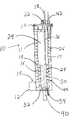
- FIG. 7is a cross-sectional view of a PrOx reactor according to another embodiment of the present invention.
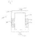
- FIG. 8is a cross-sectional view of a heat exchanger component according to another embodiment of the present invention.
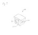
- FIG. 9is a perspective view of a heat exchanger component according to another embodiment of the present invention.
- FIG. 10is a front view of the heat exchanger component of FIG. 9 ;
- FIG. 11is a cross-sectional view of the heat exchanger component of FIG. 10 along line 11 ;
- FIG. 12is a perspective view of a heat exchanger component according to another embodiment of the present invention.
- FIG. 13is a top view of a heat exchanger component according to another embodiment of the present invention.
- FIG. 14is a cross-sectional view of the heat exchanger component of FIG. 13 along line 14 ;
- FIG. 15is top view of a portion of a heat exchanger according to another embodiment of the present invention.
- FIG. 16is front view of a heat exchanger component according to another embodiment of the present invention.
- FIG. 17is a cut away top view of the heat exchanger component of FIG. 16 along line 17 ;
- FIG. 18is an exploded view of a PrOx reactor according to another embodiment of the present invention.
- FIG. 19is a schematic view of fluid flow through the reactor of FIG. 18 .
- the temperature of the PrOx reactor catalystis preferably maintained above a lower level, and below a maximum level so that the selectivity for carbon monoxide oxidation over hydrogen oxidation is maintained.
- the volume of the catalyst bedshould be as small as possible, and the system should have as few parts as possible for ease of manufacturing.
- the PrOx reactors of the present inventionincorporate and embody improvements with respect to balancing these conflicting requirements.
- FIGS. 1 and 2show a first embodiment of the present invention.
- the reactor 10is shown in perspective in FIG. 1 , and in cross section in FIG. 2 .
- the reactor 10includes a reactor body 11 .
- a reformate inlet 12has an air inlet 14 , through which an oxygen-containing gas (either pure oxygen, or oxygen mixed with other gases, such as in air) is mixed with the reformate prior to entering the reactor 10 .
- the air inletis directed into the reactor wherein oxygen is mixed with the reformate stream at a location inside the reactor body 11 .
- Oxygen and airare generally used as synonyms herein, except in discussing particular chemical reactions.
- the rate of flow of the oxygenis usually controlled, and the flow may be adjusted to maintain a desired ratio between the amount of carbon monoxide entering the reactor 10 and the amount of oxygen.
- the desired ratiois approximately two oxygen atoms (i.e., one diatomic oxygen molecule) per carbon monoxide molecule.
- the reformate and oxygen mixtureenters the reactor 10 and flows into a catalyst bed 17 .
- the catalyst bed 17is optionally, and preferably, preceded by a non-catalytic cooling bed 16 optimized for temperature equilibration of the reformate.
- the cooling bed 16is preferably filled with heat-conducting material, such as metal shot, to optimize heat exchange, and the catalyst bed 17 is typically granular.
- Other physical formsare contemplated, examples of which are discussed below.
- the catalyst usedmay be any of those known in the art which are suitable for the selective oxidation of carbon monoxide, examples of which include Pt/ ⁇ -Al 2 O 3 and Au/ ⁇ Fe 2 O 3 .
- a wide variety of catalysts for promoting the PrOx reactionare known. Such catalysts are easily available from commercial catalyst vendors, and their compositions are typically proprietary. The approximate temperatures ranges for use, and the physical parameters of the catalyst used may be any of those commonly used in the art.
- the properties of candidate catalystshave to be evaluated in the actual proposed design before final selection of a catalyst for development or production.
- catalystscome in a wide variety of physical forms. In addition to classical porous pellets and powders, catalysts on any of a large variety of supports are suitable for use.
- Thesemay be pellets, but also include monoliths, such as the ceramic and metal honeycombs use in automotive catalytic converters, metal and ceramic foams, and other monolithic forms, such as catalyst coated on tubes of a heat exchanger, as described below.
- the catalystsmay be coated onto the supports, or impregnated into them, or may comprise extruded or otherwise formed catalyst-containing materials. Any of these catalyst chemistries and forms is potentially suitable for catalyzing the PrOx reaction.
- the reformate flowing through the catalyst bed 17undergoes an exothermic preferential oxidation reaction in which carbon monoxide is selectively oxidized.
- a cooling tube 18may be embedded in the catalyst bed 17 and in the non-catalytic cooling bed 16 .
- a favorable temperature for the PrOx reactionfalls within the range of from about 75° C. to about 300° C. More preferably the temperature range should be from about 100° C. to about 250° C.
- a two phase water/steam cooling mediumis routed through the cooling tube 18 in a direction countercurrent to the direction of flow of the reformate.
- Two phasesare not necessarily present throughout the entire length of cooling tube 18 , but are present in at least a portion of the cooling tube 18 as it passes through the beds 16 and 17 .
- Wateris typically fed to the reactor 10 in a substantially single phase liquid form and is then at least partially vaporized by heat absorbed as it passes through cooling tube 18 within the reactor body 11 , creating a two phase system.
- the point at which the water is initially heated to its boiling pointvaries depending on the operating conditions of the reactor 10 .
- the point within the cooling tube 18 at which it reaches its boiling pointmay vary substantially without affecting the carbon monoxide concentration present in the reformate exit stream from the reactor 10 .
- the two phase systemis advantageous in that it allows the removal of heat from the exothermic selective oxidation reaction without an increase in the temperature of the cooling medium. Rather, the heat removed from the catalyst bed 17 performs work in the form of a vaporization phase change. In this way, the reactor 10 is able to deal with transitory power demands caused by, for example, an increased need for hydrogen at a fuel cell (not shown) without the catalyst bed 17 temperature rising to a point at which it does not operate effectively in the selective oxidation of carbon monoxide. To the extent that the water in the cooling tube 18 is allowed to completely vaporize, the steam within the cooling tube will become superheated to the temperature of the reformate, and not operate effectively to reduce the temperature of the reformate. In order to maintain a two phase system within the cooling tube 18 , the flow of water through the cooling tube 18 is adjusted as needed to maintain some liquid water throughout most or all of cooling tube 18 .
- Controlling the pressure within the cooling tube 18may additionally be used to maintain the temperature of the two phase system (by adjusting the boiling point of water).
- Wateris inlet to the cooling tube 18 through inlet 42 and outlet at 44 .
- the exiting stream of water/steamexits the reactor 10 and is then optionally integrated into the larger fuel processing system of which the PrOx reactor 10 is a part.
- the steammay be directed to a steam separator, an auxiliary heater, a heat exchanger, or a steam reformer located separately from the PrOx reactor. In this manner the efficiency of the system is maximized by using heat generated in the exothermic selective oxidation reaction in other areas of the fuel processing system requiring the addition of heat or steam. It should be noted that if the water is entirely evaporated in the final portion of its flow path through the reactor, such as in cooling bed 16 , the temperature control desired can still be obtained.
- the reformate mixtureflows into a manifold 20 where it is optionally and preferably mixed with a second addition of oxygen from air inlet 22 .
- the amount of oxygen added through inlet 22is generally in the range of from about 10% to about 30%, or sub-ranges therein, preferably about 20%, of the initial amount added through inlet 14 .
- the mixtureflows into catalyst bed 24 located annularly interior to gap 26 which contains the first catalyst bed 17 , and through which the first cooling tube 18 is routed.
- the catalyst 24may be any of the well known PrOx catalysts as discussed above.
- the mixtureagain undergoes the exothermic selective oxidation reaction.
- the reactionis preferably allowed to proceed adiabatically in catalyst bed 24 .
- the now CO-depleted mixtureflows out of catalyst bed 24 , through a second set of cooling coils 28 which are optionally surrounded by additional PrOx catalyst or additional steel shot.
- the cooling coils 28are coiled around a cylindrical central region 30 .
- the central region 30is blocked off, and may be hollow, contain insulation, or may have additional reforming equipment contained therein.
- the reformateflows into manifold 32 where it is directed out of the reactor through outlet 40 .
- Outlet 38is optionally and preferably connected to water inlet 42 .
- the water of the cooling coils 28is preferentially heated from an inlet temperature in the range of from about 20° C. to 60° C. to an outlet temperature of about 90° C. to about 120° C. This part of the coolant flow is substantially a single phase liquid.
- the water exiting from outlet 38is optionally recycled to the inlet 42 of the higher temperature section. However, a fresh feed of water to inlet 42 may be used in addition, or in place of the water from outlet 38 .
- the temperature of the reformatemay also be regulated to prevent condensation of water from the reformate onto the catalysts.
- the moisture content of the reformatecan be reduced, for example by provision of a condenser, or by adjustment of the steam to carbon ratio, to prevent condensation in the beds.
- FIG. 3shows another embodiment of the present invention wherein the PrOx reactor 60 includes the use of a two phase water cooling system.
- the water/steamis contained within a helical tube 62 .
- the helical tube 62coils around a central core 64 that is a hollow space contained within a sealed chamber.
- core 64may contain an insulating material, a heat exchanger, or another reforming reactor module for preparation of a hydrocarbon fuel for use in a PEM fuel cell.
- the reforming reactor moduleincludes a Low Temperature Shift (LTS) module located in core 64 .
- LTSLow Temperature Shift
- a LTS moduleis preferred in that it is temperature compatible with a PrOx reactor, and additionally, the reformate can easily be routed directly from the LTS module to an inlet of a PrOx reactor.
- the reactorhas a reformate inlet 70 to which is supplied reformate having a temperature typically within the range of from about 250° C. to about 350° C.
- the helical tube 62is typically constructed of copper or stainless steel.
- the helical tube 62is surrounded by fins 66 creating a first tube/fin assembly 68 . Additional tube/fin assemblies may be provided.
- the fins 66are preferably constructed of a corrosion resistant material capable of withstanding the operating temperatures of the system.
- the preferred shapes for the fins 66are square or rectangular, although other shapes could easily be substituted.
- the number of fins 66 in this embodimentis sixteen per inch, although a lesser or greater number could be substituted as desired depending on the details of system design.
- the fins 66are preferably affixed to the tube/fin assembly 68 . This may be done by silver soldering, nickel brazing, or press fitting the fins onto the tubes, with or without flanges or washers, to affix the fins 66 in place.
- the tube/fin assembly 68may be treated to prevent corrosion, for example, by plating with nickel or other corrosion-resistant material.
- any or all of the fins and tubingmay be wash-coated with a PrOx catalyst.
- a PrOx catalystAs discussed above, many suitable catalysts exist for performing the PrOx reaction. It is preferred that a catalyst which displays optimal activity and selectivity for reacting CO without substantially reacting hydrogen throughout the operating temperature range is selected.
- a typical catalystis a group VIII metal, or sometimes a Group VIB or VIIB metal, usually with selectivity promoters based on non-noble metals or metal oxides.
- the helical tube 62 and the fins 66are contained between a cylindrical outer tube 74 and cylindrical inner core 64 which are concentrically arranged.
- the reactor of this embodimentcontains three sections, A, B, and C. Reformate and oxygen enter section A through inlet 70 , where they are cooled by passing over the helical tube 62 which contains two phase water/steam. The temperature of the reformate is lowered to be in the range of from about 100° C. to about 200° C. Section A of the reactor 60 does not include catalyst. Passing through section A lowers the temperature of the reformate to a temperature more favorable for the selective oxidation reaction.
- the tube/fin assembly 68 within section B of the reactor 60is wash coated with a selective oxidation catalyst.
- the washcoating embodiment of this embodimentis preferred in many cases, especially mobile applications, because it is more durable and resistant to attrition than pellets.
- the catalystwill operate at a temperature very close to that of the coolant, improving control of reaction temperatures.
- other physical forms of the catalystmay also be used, particularly catalyst-coated foams or monoliths, or even pellets in stationary applications.
- the reformateundergoes the exothermic selective oxidation reaction in section B and raises the temperature of the reformate as indicated qualitatively by dashed line 106 of FIG. 4 .
- Sections A, B, and C of the reactor 60 of FIG. 3correspond to sections A, B, and C of FIG. 4 .
- Helical tube 62absorbs heat, and within the tube 62 water is vaporized to steam.
- the temperature of the helical tube 62 (and of the enclosing fins 66 )remains substantially constant where the two phase system is maintained.
- the boiling point of the wateris dependent on pressure, and the temperature of the steam/water mixture is maintained at the boiling temperature as long as the two phases are present.
- the operating pressure within the helical tube 62is generally maintained in the range of from about 1 atmosphere to about 10 atmospheres.
- the pressure within the tuberemains essentially constant and is controlled by an external pressure regulating device, such as a variable speed or pressure pump, a regulator valve, an orifice, or functionally similar known devices.
- an external pressure regulating devicesuch as a variable speed or pressure pump, a regulator valve, an orifice, or functionally similar known devices.
- the cooling wateris maintained as a one phase liquid, or a two phase liquid/vapor system substantially throughout at least sections B and C of the reactor 60 .
- Additional airmay be added at inlet 76 , and further selective oxidation of the reformate occurs in section C of the reactor 60 .
- the amount of air added through injector 76is typically 10 to 30% of the total air introduced to the system, more preferably, about 20%.
- Air injectorspreferably inject the air through tubes having a plurality of holes facing in a direction countercurrent to the flow of reformate to improve mixing. Mixing may be enhanced if required throughout the reactor by the provision of mixing chambers, turbulence-creating devices, diffusing beds, and other known means. The specific location of the air inlets is different for other embodiments. Also, more or less additions may be present in a reactor.
- the temperature of the reformateincreases upon the selective oxidation caused by the second addition of oxygen as indicated qualitatively by line 108 .
- no additional airis added, and the temperature of the reformate continues to decrease as it moves through the reactor with the temperature profile shown qualitatively by line 106 .
- FIG. 3shows a reactor having two air inlets, other embodiments may include more or less than two air inlets, or may include air bleeds.
- a final air bleedmay be provided through inlet 80 and injector of distributor 81 , proximate to the outlet 82 . This air is conveyed to a fuel cell downstream from a PrOx, where it oxidizes any CO adsorbed to the fuel cell membrane catalysts.
- the total amount of oxygen added to the systemis controlled by a single controller (not shown) in response to the level of CO predicted by a system map of the reformer, or a measured value.
- the oxygencan be drawn from a common source and distributed among the various feeds as a proportion of the whole. This may be done with calibrated orifices, delivering a fixed fraction of the total oxygen supply to each air inlet; or with valves or other equivalent methods well known in the art.
- the rate of water fed to the helical tube 62is controlled to maintain a water/steam two phase system through at least reactor 60 sections C and a substantial portion of B.
- the boiling temperature of waterat the system pressure of the water, controls the temperature profile of the principal reaction portion of the PrOx catalyst, and of the reformate flowing over it, so as to maintain the temperature in the optimal operating range of the particular catalyst being used.
- the flow rateis adjusted as needed, it is generally possible to maintain the flow rate at a constant level through a wide range of operating conditions, including varying system demands.
- the presence of two phase watermakes the system resilient to transient power demands.
- the point within the helical tube 62 at which the system becomes a two phase systemmay vary substantially throughout the length of the reactor 60 , particularly within sections A and B, with little effect on the final level of CO in the reformate, as long as at least part of the length contains the two phase water/steam mixture.
- the operating temperature of the reactorvaries with position within the reactor.
- FIG. 4is a schematic plot 100 showing qualitatively how the temperature within the reactor 60 changes with position.
- the cooling water/steam temperature within the helical tube 62is indicated by the solid line 104 .
- the plotted embodimentassumes section A contains two-phase water, with no significant length of the tube 62 containing pure steam.
- the reformate (gas-phase) temperatureis qualitatively indicated by the dashed line 106 .
- Line 106shows the qualitative temperature profile where the reactor 60 is receiving an oxygen injection through inlet 76 .
- Line 106shows the temperature profile where there is only a single addition of oxygen to the reactor 60 .
- the temperature profile of the reformate as it flows through the reactoris the same whether there are two oxygen additions up to the point of the second addition. Therefore, the temperature profile of both up to the point of the second addition, if present, is indicated by line 106 .
- FIG. 5shows another embodiment of a PrOx reactor 200 .
- Reformateenters the reactor through a first inlet 202 .
- the reformatepreferably enters the reactor after being cooled to a temperature in the range of from about 60° C. to about 130° C., more preferably in the range of from about 70° C. to about 90° C. Cooling of the reformate prior to feeding to the reactor 200 precipitates out water vapor from the reformate stream, preventing the condensation of water from the reformate in the PrOx reactor or the PEM fuel cell.
- Other embodimentsemploy a water removal system (not shown) to remove water that may condense prior to entry, within the reactor, or between the reactor and a fuel cell stack.
- Oxygenis added to the reformate through air inlet 204 .
- the airis added at ambient temperature. In other embodiments, the air is added separately to a reactor and mixed with the reformate therein.
- the reformate/air mixtureflows over a catalyst bed 206 .
- the catalystsupported on a monolith or foam, typically reticulated, to provide better radial and axial heat transfer in comparison to a packed bed.
- the CO presentis selectively oxidized to carbon dioxide.
- the amount of CO presentis reduced to a level in which the reformate is suitable for use with a PEM fuel cell.
- the catalyst 206 of the reactor 200is distributed annularly about a core 208 within the reactor.
- a coremay be hollow, contain insulation, be solid, or may contain another unit used in the processing of a hydrocarbon.
- the core 208occupies the center of the reactor 200 , and the catalyst bed is positioned radially outward beginning at the outer edge of the core 208 , and extending towards the outer wall 210 of the reactor.
- the reactor 200is jacketed with a cooling water jacket 212 positioned within the outer wall 210 . In other embodiments, the jacketing is not contained within a reactor wall, but either internal or external to the wall.
- the core 208results in the selective oxidation reaction occurring generally closer to the cooling jacket 212 , in contrast to a reactor not containing core region 208 , and results in a more even temperature profile in a radial direction at each point throughout the catalyst bed 206 .
- the temperature in the catalyst bed 206 at any point having axially the same position, and radially a different positionis closer to equal than without the use of the core 208 .
- the temperature of the wateris preferably in the range of from about 1° C. to about 70° C.
- a portion of the waterbecomes heated to a temperature wherein it vaporizes to steam creating a two phase system.
- the pressure within the jacket 212is preferably maintained in the range of from about 1 to about 10 atmospheres. Therefore, the boiling temperature of the water in the jacket may be at temperatures of about 100° C. to about 200° C., depending on the pressure in the jacket.
- Use of the two phase water systemhas the advantage of allowing the temperature of the jacket 212 to remain substantially constant when the pressure is substantially constant, while still absorbing heat which is in turn used to vaporize liquid water.
- FIG. 6shows a graph 250 which charts the temperature profile obtained in the operation of a reactor according to the embodiment shown in FIG. 5 .
- the horizontal axis 252indicates position within the reactor, and the vertical access 254 qualitatively indicates the temperature.
- Reformate temperatureis indicated by line 256 , where the left hand side is the entry temperature, and the right hand side the exiting temperature.
- Cooling waterflows countercurrent to the reformate stream, and enters on the right and exits on the left according to line 258 .
- the two phase vaporization of the cooling wateroccurs near or at point 260 .
- the temperature of the two phase systemstops increasing at that point.
- the PrOx reactor 200 of this exampleis especially suitable when the concentration of CO in the reformate has previously been reduced by a first PrOx reactor, for example one integrated with a reformer, so that the reactor 200 is performing essentially a final cleanup function. It is also particularly suited to use with a fuel cell stack operating at a temperature above that typically used in a PEM fuel cell which is about 70° C. to about 85° C. Such a fuel cell stack may operate at temperature at from about 90° C. to about 150° C., which has become possible with the use of high-temperature tolerant PEM membranes and/or membrane electrode assemblies.
- FIG. 7shows another embodiment of a PrOx reactor according to the present invention shown generally as reference numeral 300 .
- the reactor 300preferably includes a reformate inlet 302 and a reformate outlet 304 .
- the reactor 300preferably includes a core 306 positioned within the reactor body 308 such that reformate fed into the reactor through the reformate inlet 302 travels about the core 306 in traversing the reactor 300 to the reformate outlet 304 .
- Airmay be mixed with the reformate within the reformate inlet 302 prior to entry into the reactor body 308 .
- other embodimentsmay have air inlets positioned such that air may be injected into the reactor body in place of, or in addition to the air added into the reformate inlet 302 .
- the reformategenerally flows around the core 306 and over a heat exchanger 310 positioned within the reactor body 308 .
- the heat exchangerwill now be described in greater detail in conjunction with FIGS. 8-16 .
- the heat exchanger 310is generally comprised of a plurality of modular rings 312 .
- a cross-sectional view of a single modular ring 312is shown in FIG. 8 .
- Each ring 312generally includes a tubular section which here is a flow tube 314 .
- the flow tube 314generally has a circular shape, but the shape is not limited, and could include such shapes as oblong, obround, triangular, polygonal, or numerous other shapes with the same beneficial results.
- Each ring 312generally includes an inlet 316 and an outlet 318 for permitting circulation of a heat exchange fluid.
- the preferred heat exchange fluid in this embodimentis water or a water and steam mixture. However, numerous heat exchange fluids could be flowed through the flow tube 314 .
- Stainless steelis the preferred material for forming the flow tube 314 . Benefits of stainless steel include its resistance to corrosion and its ability to withstand heat and pressure.
- the heat exchangergenerally includes a connector between each tubular section, or flow tube 314 for permitting flow from the outlet 318 of one to the inlet 316 of another.
- the connectorpreferably includes a manifold 320 .
- Each modular ring 312generally includes a single manifold 320 which directs fluid flow into, out of, and within each modular ring 312 .
- the manifold 320is shown separately in FIGS. 9-11 .
- the manifold 320generally includes a section transfer inlet 322 and a section transfer outlet 324 which form a fluid inlet and fluid outlet into the modular ring 312 .
- the manifold 320also generally include a manifold inlet 326 and a manifold outlet 328 into which the flow tube 314 is preferably secured with fluid tight seals.
- a plurality of modular rings 312are connected to one another.
- the manifolds 320 of the modular rings 312generally include bolt holes 330 which extend through the manifold for securing one manifold to another.
- a sealis generally placed between the manifolds to ensure a fluid tight seal.
- FIGS. 12-14show a preferred spool seal, shown generally as reference numeral 350 .
- the spool seal 350generally includes a generally cylindrical body 352 having a bore 354 through its center.
- the spool seal 350generally includes an annular central ridge 356 and annular terminal ridges 358 proximate to both ends of the cylindrical body 352 .
- the central ridge 356 and terminal ridges 358form annular channels 360 between them.
- O-rings 362are generally placed into the channels 360 .
- sealswhich are already known and in the relevant prior art may be used to form a fluid tight seal between connected manifolds. Some of these may include various gaskets, O-rings, swage, compression fittings, and numerous other types of seals which are well known to those practicing the art.
- the spool seal 350is loaded with O-rings, and inserted into the section transfer inlet 322 of the manifold 320 .
- the spool seal 350is inserted such that the bore 354 aligns with the section transfer inlet 322 to allow fluid flow through the bore 354 .
- One half of the spool seal 350is generally inserted into the section transfer inlet 322 and one half extends outward for insertion into a section transfer outlet of another manifold 324 .
- the correct positioning of the spool seal 350is generally governed by stops 323 within the manifold 320 as shown in FIG. 11 .
- connection between the modular rings 312is preferably made with bolts or other nonpermanent means such that the modular rings 312 can later be unconnected without destroying the ring or its component parts.
- swaging, welding, or other permanent means for connecting the modular rings 312may be done if additional strength is desired.
- Each manifold 320 of the heat exchangeris preferably sized, configured, and attached to the adjacent manifolds such that the joined manifolds 320 provide sufficient structural rigidity to transport or operate the heat exchanger with reduced support for the joined tubular sections.
- the manifolds 320may be used to join together modular rings 312 of different sizes. For example if the reactor 300 were larger through one section, a modular ring 312 having a relatively larger diameter could be used.
- Each of the flow tubes 314has a flow path of from its inlet to its outlet of a defined flow path length, and two different flow tubes 314 , connected by a manifold, may have differing flow path lengths.
- the flow tubes 314 of the heat exchanger 310are spaced and generally provide fluid flow within the various flow tubes 314 along respective planes substantially parallel to each other.
- the manifolds 350provide fluid flow in a direction angular to the planes of flow in the flow tubes 314 .
- the angular direction of flow through the manifolds 350is approximately ninety degrees with respect to the flow in the flow tubes 314 .
- the modular rings 312 of the heat exchanger 310generally include fins 364 .
- the fins 364are preferably cast aluminum. More specifically, the fin is preferably cast from a material having a high thermal conductivity such as aluminum Alloy 360 .
- the flow tube 312generally has an inner surface 366 and an outer surface 368 .
- the fins 364are generally connected to and extending out of the outer surface 368 .
- the heat exchanger 310preferably includes a plurality of connected modular rings 312 and the fins 364 of adjacent modular rings 312 are preferable offset such that they create more turbulent flow for any fluid flowing over the heat exchanger.
- the fins 364are preferably axially misaligned between each modular ring 312 .
- FIG. 15shows a view of two stacked modular rings 312 .
- the fins 370 from the top modular ringare visible over the flow tube 372 .
- the fins 374 from the bottom modular ringare visible only because they are misaligned with those from the top modular ring.
- Some of the modular rings 312 of the heat exchanger 310 used in the reactor 300are preferably wash coated with a PrOx catalyst 365 .
- the PrOx catalyst 365preferably adheres well to the modular rings.
- the catalystmay be any of the well known PrOx catalysts discussed elsewhere in this application, or in the prior art. It can be appreciated that when the heat exchanger is used in other types of applications, a catalyst other than a PrOx catalyst may be washcoated onto the modular rings 312 . In certain instances it may be beneficial to include a wash coated catalyst on an interior surface of the tubular section of the modular rings.
- a heat exchangermay include a first modular ring which is wash coated with a PrOx catalyst, a second modular ring which is not wash coated, and a third modular ring which is again wash coated with a PrOx catalyst. Numerous variations of this concept immediately come to mind and are well within the skill of one of ordinary skill in the art.
- Other propertiesalso may vary between individual modular rings within the same heat exchanger. These may include different number of fins, spacing between fins, alignment of fins, material comprising the fins, coating on the fins, heat transfer coefficient, surface area, shape of individual fins, size of the individual fins, orientation with respect to the flow tubes, and type of attachment to the flow tube.
- the reactor 300 of FIG. 7generally receives reformate gas at approximately 300° C. to which air is added at the reformate inlet 302 .
- Liquid watergenerally enters the heat exchanger 310 at the opposite end, and flows in a countercurrent direction to the reformate. The water generally turns to a two-phase water steam mixture with in the heat exchanger 310 .
- the heat exchangerpreferably maintains a desirable thermal profile within the reactor 300 .
- Reaction of the reformateis preferably catalyzed by the PrOx catalyst 365 .
- the now reacted reformateleaves the reactor 300 through reformate outlet 304 .
- One advantage of this reactoris it does not generally require additional air inlets, although, the use of them is contemplated as needed.
- the heat exchanger 310 used in conjunction with reactor 300provides a benefit in that it is easily manufactured.
- a tubular conduit of a first metalis formed into a tubular section of the desired shape and size.
- the first metalis preferably stainless steel.
- the tubular sectionis shown in FIGS. 16 and 17 with an attached manifold 320 .
- the tubular sectionis placed in a die, and a second metal is cast onto an outer surface of the tubular section in the form of fins.
- the manifold 320is not connected to the tubular section during die casting.
- the second metalis preferably aluminum.
- the finsare then optionally wash coated with a catalyst for promoting a desired reaction in a heat transfer fluid intended to contact the fins during heat transfer operations.
- the final step in assembling the heat exchanger 310is connecting the tubular sections to a connector and connecting at least two of the tubular sections together with the connector. The number of tubular sections connected together will vary depending on system requirements.
- the reactor 400generally includes a plurality of plates 402 which are connected such that heat transfer may be performed between two fluids traveling through channels 404 formed between adjacent plates 402 .
- the two fluidsare generally reformate, water, or a water/steam mixture.
- An interior surface 406 of the plates 402 through which the reformate is routedis preferably wash coated with a PrOx catalyst 408 .
- a portion of the channelmay be packed with a PrOx catalyst in any of the well know catalyst forms discussed elsewhere in this application.
- the reactor 400is generally understood as a plate and frame type heat exchanger with a reforming capacity provided by the inclusion of a catalyst.
- Flow through the reactor 400is generally countercurrent as shown in FIG. 19 .
- Reformategenerally enters the reactor 400 through a reformate inlet 410 .
- Liquid watergenerally enters the reactor 400 through a water inlet 412 .
- the reformate and water/steamthen generally proceed through the reactor exchanging heat through the plates 402 which separate the channels 404 through which they flow.
- the flow through the channelsis preferably directed and made turbulent by the presence of raised protuberances 414 .
- the pattern of the protuberances 414may be selected based on the degree to which it is desirable to make the fluid path tortuous.
- One system considerationis that additional pressure is required to move a fluid through a tortuous fluid path. It is preferable to make the fluid path within a channel 404 travel diagonally across a plate 402 .
- the flow of fluids between channelsis done through openings 403 in the plates 402 .
- the reformategenerally exits the reactor through a reformate outlet 416 .
- the water/steamgenerally exits the reactor through a water/steam outlet 418 . While the two fluids are shown here entering and exiting the reactor 400 through different end plates 420 , 422 , in other embodiments, both fluids enter and exit the system through the same end plate 420 , and the plates 402 and channels 404 are arranged accordingly as is well understood by one of ordinary skill in the art.
Landscapes
- Chemical & Material Sciences (AREA)
- Engineering & Computer Science (AREA)
- Organic Chemistry (AREA)
- Chemical Kinetics & Catalysis (AREA)
- Mechanical Engineering (AREA)
- General Engineering & Computer Science (AREA)
- Physics & Mathematics (AREA)
- Thermal Sciences (AREA)
- Combustion & Propulsion (AREA)
- Inorganic Chemistry (AREA)
- General Chemical & Material Sciences (AREA)
- Oil, Petroleum & Natural Gas (AREA)
- Hydrogen, Water And Hydrids (AREA)
- Carbon And Carbon Compounds (AREA)
Abstract
Description
CO+½O2→CO2 (1)
Desirably, the amount of O2used for the PrOx reaction will be no more than about two times the stoichiometric amount required to react the CO in the reformate. If the amount of O2exceeds about two to three times the stoichiometric amount needed, excessive consumption of H2results. On the other hand, if the amount of O2is substantially less than about two times the stoichiometric amount needed, insufficient CO oxidation may occur, making the reformate unsuitable for use in a PEM fuel cell. The essence of the PrOx process is described in the literature, for example, in U.S. Pat. Nos. 1,366,176 and 1,375,932. Modern practice is described, for example, in, “Preferential Oxidation of CO over Pt/γ-Al2O3and Au/α-Fe2O3: Reactor Design Calculations and Experimental Results” by M. J. Kahlich, et al. published in theJournal of New Materials for Electrochemical Systems,1988 (pp. 39-46), and in U.S. Pat. No. 5,316,747 to Pow et al.
Claims (19)
Priority Applications (1)
| Application Number | Priority Date | Filing Date | Title |
|---|---|---|---|
| US10/463,763US7507384B2 (en) | 2002-06-13 | 2003-06-13 | Preferential oxidation reactor temperature regulation |
Applications Claiming Priority (2)
| Application Number | Priority Date | Filing Date | Title |
|---|---|---|---|
| US38855502P | 2002-06-13 | 2002-06-13 | |
| US10/463,763US7507384B2 (en) | 2002-06-13 | 2003-06-13 | Preferential oxidation reactor temperature regulation |
Publications (2)
| Publication Number | Publication Date |
|---|---|
| US20040037758A1 US20040037758A1 (en) | 2004-02-26 |
| US7507384B2true US7507384B2 (en) | 2009-03-24 |
Family
ID=29736493
Family Applications (1)
| Application Number | Title | Priority Date | Filing Date |
|---|---|---|---|
| US10/463,763Expired - LifetimeUS7507384B2 (en) | 2002-06-13 | 2003-06-13 | Preferential oxidation reactor temperature regulation |
Country Status (6)
| Country | Link |
|---|---|
| US (1) | US7507384B2 (en) |
| EP (1) | EP1581784A4 (en) |
| JP (1) | JP2006502938A (en) |
| AU (1) | AU2003243601A1 (en) |
| CA (1) | CA2489299A1 (en) |
| WO (1) | WO2003106946A2 (en) |
Cited By (1)
| Publication number | Priority date | Publication date | Assignee | Title |
|---|---|---|---|---|
| US20110272123A1 (en)* | 2009-06-29 | 2011-11-10 | Thomas Bruce Avis | Spiral heat exchanger for hydrodesulfurizer feedstock |
Families Citing this family (11)
| Publication number | Priority date | Publication date | Assignee | Title |
|---|---|---|---|---|
| US20040126297A1 (en)* | 2002-12-27 | 2004-07-01 | Visteon Global Technologies, Inc. | Integrated catalyst-heat exchanger and method of oxidizing carbon monoxide in a hydrogen reformer of a vehicle fuel cell system |
| CA2528194A1 (en)* | 2003-06-16 | 2005-01-06 | Cerionx, Inc. | Atmospheric pressure non-thermal plasma device to clean and sterilize the surface of probes, cannulas, pin tools, pipettes and spray heads |
| DE602004019076D1 (en) | 2004-08-05 | 2009-03-05 | Saudi Basic Ind Corp | Process with a catalyst-coated heat exchanger |
| JP2008509873A (en)* | 2004-08-11 | 2008-04-03 | ヌヴェラ・フュエル・セルズ・インコーポレーテッド | Heat exchanger coated with catalyst |
| US7572304B2 (en)* | 2004-09-28 | 2009-08-11 | Texaco Inc. | Apparatus and method for preferential oxidation of carbon monoxide |
| JP4542205B2 (en)* | 2008-05-30 | 2010-09-08 | パナソニック株式会社 | Fuel processor |
| CA2835481A1 (en)* | 2011-05-09 | 2012-11-15 | Fluor Technologies Corporation | Internal heat exchanger for distillation column |
| ES2431491B1 (en)* | 2013-08-07 | 2014-09-29 | Abengoa Hidrógeno, S.A. | Carbon monoxide preferential oxidation reactor |
| US10479680B2 (en)* | 2015-01-14 | 2019-11-19 | Raven Sr, Llc | Electrically heated steam reforming reactor |
| CN110790225A (en)* | 2019-10-24 | 2020-02-14 | 中石化宁波工程有限公司 | Isothermal converter with double cooling systems |
| WO2022173416A1 (en)* | 2021-02-09 | 2022-08-18 | Raytheon Technologies Corporation | Compact two-phase heat exchanger |
Citations (486)
| Publication number | Priority date | Publication date | Assignee | Title |
|---|---|---|---|---|
| US1366176A (en) | 1918-04-18 | 1921-01-18 | Terrey | Treatment or purification of mixtures of hydrogen and carbon monoxid for the separation therffrom of the latter |
| US1375932A (en) | 1918-03-14 | 1921-04-26 | Rideal Eric Keightley | Purification of hydrogen |
| US1797426A (en) | 1928-05-15 | 1931-03-24 | Pont Ammonia Corp Du | Manufacture of hydrogen |
| US2051363A (en) | 1936-08-18 | Process fob the preparation of | ||
| US2220849A (en) | 1938-08-29 | 1940-11-05 | Kellogg M W Co | Method for forming synthesis gas |
| US2759805A (en) | 1952-04-01 | 1956-08-21 | United Gas Improvement Co | Method of carrying out catalytic reactions |
| US2795559A (en) | 1954-04-01 | 1957-06-11 | Texas Co | Production of hydrogen-nitrogen mixtures |
| US3014787A (en) | 1959-06-08 | 1961-12-26 | Exxon Research Engineering Co | Production of hydrogen and carbon monoxide |
| US3069348A (en) | 1959-07-22 | 1962-12-18 | Socony Mobil Oil Co Inc | Multi-stage, multi-zone static bed reforming process and apparatus therefor |
| US3159450A (en) | 1962-11-29 | 1964-12-01 | Atlantic Res Corp | Catalytic reactor and method for controlling temperature of the catalyst bed therein |
| US3180813A (en) | 1961-05-31 | 1965-04-27 | Consolidation Coal Co | Electrolytic process for producing hydrogen from hydrocarbonaceous gases |
| US3216782A (en) | 1962-10-09 | 1965-11-09 | Engelhard Ind Inc | Process for selectively removing carbon monoxide from hydrogen-containing gases |
| US3216783A (en) | 1962-10-09 | 1965-11-09 | Engelhard Ind Inc | Process for selectively removing carbon monoxide from hydrogen-containing gases |
| US3278452A (en) | 1959-12-24 | 1966-10-11 | Pullman Inc | Production of hydrogen-containing gases |
| US3288646A (en) | 1961-07-21 | 1966-11-29 | Svensk Ackumulator Aktiebolage | Method of utilizing hydrocarbon as fuel in fuel cells |
| GB1060166A (en) | 1963-09-10 | 1967-03-01 | Mobil Oil Corp | Catalytic conversion of combustible gases |
| US3334971A (en) | 1964-08-18 | 1967-08-08 | Chemical Construction Corp | Catalytically reforming hydrocarbon and steam mixtures |
| US3367882A (en) | 1962-02-08 | 1968-02-06 | Walton H. Marshall Jr. | Ammonia synthesis gas process |
| US3375140A (en) | 1964-09-08 | 1968-03-26 | Leesona Corp | Fuel cell with hydrogen purification means and process of using same |
| US3387942A (en) | 1965-05-10 | 1968-06-11 | Catalysts & Chemicals Inc | Production of hydrogen |
| US3395004A (en) | 1964-01-20 | 1968-07-30 | Exxon Research Engineering Co | Low-temperature, high-pressure, catalytic, partial conversion of naphtha hydrocarbons to hydrogen |
| US3397028A (en) | 1966-08-11 | 1968-08-13 | Bbc Brown Boveri & Cie | High-temperature fuel element apparatus |
| US3438759A (en) | 1965-12-03 | 1969-04-15 | Cons Natural Gas Svc | Gas reformer and control means |
| US3446674A (en) | 1965-07-07 | 1969-05-27 | United Aircraft Corp | Method and apparatus for converting hydrogen-containing feedstocks |
| US3446672A (en) | 1965-07-07 | 1969-05-27 | United Aircraft Corp | Method and apparatus for converting hydrogen-containing feedstocks into electrical energy |
| US3451949A (en) | 1963-01-15 | 1969-06-24 | Haldor Frederik Axel Topsoe | Catalyst for reforming hydrocarbons |
| US3462308A (en) | 1967-11-07 | 1969-08-19 | Union Carbide Corp | Method and means for flowing a gas in a fuel cell system |
| US3477942A (en) | 1967-07-28 | 1969-11-11 | Us Interior | Hydrocarbon fuels from coal or any carbonaceous material |
| US3499797A (en) | 1966-04-28 | 1970-03-10 | Texas Instruments Inc | Water gas shift converter and fuel cell system therewith |
| US3516807A (en) | 1966-04-06 | 1970-06-23 | Texas Instruments Inc | Apparatus for producing hydrogen gas by the partial oxidation of a carbonaceous fuel containing hydrogen |
| US3524720A (en) | 1967-04-24 | 1970-08-18 | Lummus Co | Process for removing sulfur dioxide from gases |
| US3531263A (en) | 1968-08-05 | 1970-09-29 | United Aircraft Corp | Integrated reformer unit |
| US3541729A (en) | 1968-05-09 | 1970-11-24 | Gen Electric | Compact reactor-boiler combination |
| US3585078A (en) | 1968-11-19 | 1971-06-15 | United Aircraft Corp | Method of reformer fuel flow control |
| US3607419A (en) | 1969-10-01 | 1971-09-21 | United Aircraft Corp | Fuel cell system control |
| US3615850A (en) | 1969-03-10 | 1971-10-26 | Gen Electric | System and process employing a reformable fuel to generate electrical energy |
| US3619144A (en) | 1969-09-15 | 1971-11-09 | Texas Instruments Inc | Apparatus for reforming hydrocarbon fuels to produce hydrogen |
| US3645701A (en) | 1967-06-19 | 1972-02-29 | Lummus Co | Reformer furnace |
| US3649360A (en) | 1970-01-16 | 1972-03-14 | United Aircraft Corp | Combined water removal and hydrogen generation fuel cell powerplant |
| US3666682A (en) | 1969-11-26 | 1972-05-30 | Texaco Inc | Water-gas shift conversion process |
| US3666423A (en) | 1969-11-26 | 1972-05-30 | Texaco Inc | Heat exchange apparatus |
| US3669751A (en) | 1967-03-15 | 1972-06-13 | Peter D Richman | Electric battery comprising a fuel cell hydrogen generator and heat exchanger |
| US3718506A (en) | 1971-02-22 | 1973-02-27 | Bbc Brown Boveri & Cie | Fuel cell system for reacting hydrocarbons |
| US3729898A (en) | 1971-06-01 | 1973-05-01 | Chemical Construction Corp | Removal of entrained matter from gas streams |
| US3731071A (en) | 1971-06-03 | 1973-05-01 | Texaco Inc | Minimum operating pressure control system and method for controlling a product separator in a catalytic reforming unit |
| US3787038A (en) | 1970-01-04 | 1974-01-22 | P Tesner | Reformer for firing reverberatory furnace and method of operating said reformer |
| US3796547A (en) | 1969-11-26 | 1974-03-12 | Texaco Inc | Heat exchange apparatus for catalytic system |
| US3909299A (en) | 1973-10-01 | 1975-09-30 | United Technologies Corp | Fuel cell system including reform reactor |
| GB1408560A (en) | 1971-11-26 | 1975-10-01 | Shell Int Research | Process for the production of hydrogenrich gas |
| US3920416A (en) | 1973-12-26 | 1975-11-18 | California Inst Of Techn | Hydrogen-rich gas generator |
| US3932147A (en) | 1971-06-28 | 1976-01-13 | Japan Gasoline Co., Ltd. | Method of reforming hydrocarbons |
| US3941869A (en) | 1972-05-23 | 1976-03-02 | Warren Fuchs | Process for exothermic reactions |
| US3955941A (en) | 1973-08-20 | 1976-05-11 | California Institute Of Technology | Hydrogen rich gas generator |
| US3959019A (en) | 1973-03-30 | 1976-05-25 | Fuji Electric Co., Ltd. | Fuel cell |
| US3961018A (en) | 1973-12-06 | 1976-06-01 | United Air Specialists, Inc. | Method for purification of gas streams by removal of acidic gases |
| US3971847A (en) | 1973-12-26 | 1976-07-27 | The United States Of America As Represented By The Adminstrator Of The National Aeronautics And Space Administration | Hydrogen-rich gas generator |
| US3981792A (en) | 1974-11-25 | 1976-09-21 | Universal Oil Products Company | Heat exchange method for series flow reactors |
| US3982910A (en) | 1974-07-10 | 1976-09-28 | The United States Of America As Represented By The Administrator Of The National Aeronautics And Space Administration | Hydrogen-rich gas generator |
| US4006099A (en) | 1975-06-16 | 1977-02-01 | Texaco Inc. | Manufacture of gaseous mixtures comprising hydrogen and carbon monoxide |
| US4006100A (en) | 1975-04-29 | 1977-02-01 | Texaco Inc. | Manufacture of gaseous mixtures comprising hydrogen and carbon monoxide |
| US4007018A (en) | 1975-12-22 | 1977-02-08 | Texaco Inc. | Production of clean synthesis or fuel gas |
| US4007017A (en) | 1975-12-22 | 1977-02-08 | Slater William L | Production of clean synthesis or fuel gas |
| US4007019A (en) | 1975-12-22 | 1977-02-08 | Texaco Inc. | Production of clean synthesis or fuel gas |
| US4008050A (en) | 1975-06-11 | 1977-02-15 | Betz Erwin C | Apparatus for combining oxygen and hydrogen |
| US4010797A (en) | 1974-03-04 | 1977-03-08 | C F Braun & Co | Heat exchanger |
| US4025612A (en) | 1974-12-13 | 1977-05-24 | Texaco Inc. | Process for the production of hydrogen |
| US4042344A (en) | 1975-05-09 | 1977-08-16 | The Broken Hill Proprietary Company Limited | Process for the production of gaseous mixtures |
| US4045960A (en) | 1975-01-15 | 1977-09-06 | Metallgesellschaft Aktiengesellschaft | Process for producing energy |
| US4056602A (en) | 1975-08-20 | 1977-11-01 | Thagard Technology Company | High temperature chemical reaction processes utilizing fluid-wall reactors |
| US4059076A (en) | 1975-04-21 | 1977-11-22 | Nissan Motor Co., Ltd. | Method and apparatus for generating reformed gas containing hydrogen and carbon monoxide from hydrocarbon fuel |
| US4060498A (en) | 1972-06-02 | 1977-11-29 | Hitachi, Ltd. | Process for steam reforming of hydrocarbons |
| US4060397A (en) | 1974-02-21 | 1977-11-29 | Shell Internationale Research Maatschappij B.V. | Two stage partial combustion process for solid carbonaceous fuels |
| US4066543A (en) | 1975-11-12 | 1978-01-03 | Texaco Inc. | Continuous process for non-catalytic oxidation of sulfite-containing waters |
| US4067958A (en) | 1976-03-10 | 1978-01-10 | Continental Oil Company | Production of a hydrogen-rich gas from a co-containing fuel gas |
| US4071330A (en) | 1976-12-22 | 1978-01-31 | United Technologies Corporation | Steam reforming process and apparatus therefor |
| US4072601A (en) | 1976-06-14 | 1978-02-07 | Antar Petroles De L'atlantique | Process and apparatus for performing endothermic catalytic reactions |
| US4073698A (en) | 1976-06-04 | 1978-02-14 | Energetics Science, Inc. | Method and device for the detection and measurement of carbon monoxide in the presence of hydrogen |
| US4074981A (en) | 1976-12-10 | 1978-02-21 | Texaco Inc. | Partial oxidation process |
| US4083799A (en) | 1973-01-08 | 1978-04-11 | Texaco Inc. | Method of steam reforming |
| US4087259A (en) | 1974-09-20 | 1978-05-02 | Kabushiki Kaisha Toyota Chuo Kenkyusho | Process for partially oxidizing hydrocarbons |
| US4088450A (en) | 1975-09-08 | 1978-05-09 | Nissan Motor Company, Limited | Hydrogen generator |
| US4094813A (en) | 1972-08-02 | 1978-06-13 | Shell Oil Company | Process and apparatus for the manufacture and cooling of gases containing hydrogen and carbon monoxide |
| US4094650A (en) | 1972-09-08 | 1978-06-13 | Exxon Research & Engineering Co. | Integrated catalytic gasification process |
| US4098589A (en) | 1976-12-22 | 1978-07-04 | United Technologies Corporation | Catalytic reaction apparatus |
| US4098587A (en) | 1976-12-22 | 1978-07-04 | United Technologies Corporation | Compact multi-tube catalytic reaction apparatus |
| US4098588A (en) | 1976-12-22 | 1978-07-04 | United Technologies Corporation | Multi-tube catalytic reaction apparatus |
| US4099383A (en) | 1976-06-21 | 1978-07-11 | Texaco Inc. | Partial oxidation process |
| US4101376A (en) | 1974-03-18 | 1978-07-18 | Metallgesellschaft Aktiengesellschaft | Tubular heater for cracking hydrocarbons |
| US4113445A (en) | 1977-01-31 | 1978-09-12 | Texaco Development Corporation | Process for the partial oxidation of liquid hydrocarbonaceous fuels |
| US4113441A (en) | 1976-03-09 | 1978-09-12 | Director-General Agency Of Industrial Science And Technology | Steam reforming reactor |
| US4121912A (en) | 1977-05-02 | 1978-10-24 | Texaco Inc. | Partial oxidation process with production of power |
| US4125090A (en) | 1975-11-25 | 1978-11-14 | Toyota Jidosha Kogyo Kabushiki Kaisha | Control method and system for car-mounted fuel reformer |
| US4140493A (en) | 1976-11-19 | 1979-02-20 | Phillips Petroleum Company | Hydrocarbon steam reforming process |
| US4153671A (en) | 1977-01-13 | 1979-05-08 | Nalco Chemical Company | Catalytic gas purification process |
| US4155987A (en) | 1976-08-26 | 1979-05-22 | Atlantic Richfield Company | Claus tail gas recovery |
| US4162290A (en) | 1976-11-19 | 1979-07-24 | Pullman Incorporated | Parallel steam reformers to provide low energy process |
| US4178758A (en) | 1976-06-21 | 1979-12-18 | Texaco Inc. | Partial oxidation process |
| US4181503A (en) | 1978-10-30 | 1980-01-01 | United Technologies Corporation | Process for alternately steam reforming sulfur containing hydrocarbons that vary in oxygen content |
| US4182795A (en) | 1978-07-10 | 1980-01-08 | Energy Research Corporation | Fuel cell thermal control and reforming of process gas hydrocarbons |
| US4183369A (en) | 1977-11-04 | 1980-01-15 | Thomas Robert E | Method of transmitting hydrogen |
| US4184322A (en) | 1976-06-21 | 1980-01-22 | Texaco Inc. | Partial oxidation process |
| US4191540A (en) | 1978-03-27 | 1980-03-04 | Chevron Research Company | Carbon dioxide acceptor process using countercurrent plug flow |
| US4199545A (en) | 1975-08-20 | 1980-04-22 | Thagard Technology Company | Fluid-wall reactor for high temperature chemical reaction processes |
| US4203950A (en) | 1977-12-27 | 1980-05-20 | United Technologies Corporation | Steam reforming reactor designed to reduce catalyst crushing |
| US4205044A (en) | 1976-09-24 | 1980-05-27 | Tecnimont S.P.A. | Reactor for catalyzed exothermic reactions |
| US4212817A (en) | 1974-06-26 | 1980-07-15 | Linde Aktiengesellschaft | Control of highly exothermic chemical reactions |
| US4216198A (en) | 1977-12-19 | 1980-08-05 | Billings Energy Corporation | Self-regenerating method and system of removing oxygen and water impurities from hydrogen gas |
| US4224298A (en) | 1977-04-14 | 1980-09-23 | Robinson Lee F | Reforming of hydrocarbons |
| US4229418A (en) | 1977-10-07 | 1980-10-21 | Shell Oil Company | Apparatus for the catalytic treatment of hydrocarbons |
| US4233276A (en) | 1979-03-30 | 1980-11-11 | Standard Oil Company (Indiana) | Process for the desulfurization of waste gases |
| US4233180A (en) | 1978-11-13 | 1980-11-11 | United Catalysts Inc. | Process for the conversion of carbon monoxide |
| US4233179A (en) | 1975-12-08 | 1980-11-11 | United Catalysts Inc. | Process for steam reforming of hydrocarbons |
| US4236941A (en) | 1979-01-22 | 1980-12-02 | General Motors Corporation | Method of producing heat treatment atmosphere |
| US4240805A (en) | 1979-03-16 | 1980-12-23 | United Technologies Corporation | Process for producing hydrogen containing gas |
| US4242105A (en) | 1979-10-10 | 1980-12-30 | Union Carbide Corporation | Process for producing methane from gas streams containing carbon monoxide and hydrogen |
| US4246235A (en) | 1978-03-13 | 1981-01-20 | Engelhard Minerals & Chemicals Corporation | Horizontal flow catalytic reactor |
| US4259414A (en) | 1979-11-29 | 1981-03-31 | Rca Corporation | Non-air polluting, non-pyrolytic upgrading of coal for cleaner and more effective electrical power generation |
| US4259312A (en) | 1977-04-18 | 1981-03-31 | Didier Engineering Gmbh | Process and apparatus for catalytically reacting a reducing gas and water vapor |
| US4259294A (en) | 1978-01-20 | 1981-03-31 | Shell Oil Company | Apparatus for the hydrogenation of heavy hydrocarbon oils |
| US4261964A (en) | 1979-07-16 | 1981-04-14 | J. M. Huber Corporation | Utilization of combustible components of a tail-gas in the manufacture of carbon black at a high production rate |
| US4277444A (en) | 1978-05-29 | 1981-07-07 | Institut Francais Du Petrole | Apparatus for converting hydrocarbons |
| US4292274A (en) | 1980-08-04 | 1981-09-29 | United Technologies Corporation | Catalytic reactor with improved burner |
| US4293315A (en) | 1979-03-16 | 1981-10-06 | United Technologies Corporation | Reaction apparatus for producing a hydrogen containing gas |
| GB2084894A (en) | 1980-10-07 | 1982-04-21 | Gen Signal Corp | Two pass endothermic generator |
| US4328008A (en) | 1979-05-30 | 1982-05-04 | Texaco Development Corporation | Method for the production of cleaned and cooled synthesis gas |
| US4328856A (en) | 1980-11-10 | 1982-05-11 | Corning Glass Works | Heat recovery wheel |
| US4337170A (en) | 1980-01-23 | 1982-06-29 | Union Carbide Corporation | Catalytic steam reforming of hydrocarbons |
| US4338292A (en) | 1980-12-08 | 1982-07-06 | Texaco Inc. | Production of hydrogen-rich gas |
| US4341737A (en) | 1979-05-22 | 1982-07-27 | The Lummus Company | Apparatus for carrying out catalytic exothermic and endothermic high-pressure gas reactions |
| US4343624A (en) | 1979-12-10 | 1982-08-10 | Caterpillar Tractor Co. | Rotating fluidized bed hydrogen production system |
| US4353712A (en) | 1980-07-14 | 1982-10-12 | Texaco Inc. | Start-up method for partial oxidation process |
| US4365006A (en) | 1981-03-26 | 1982-12-21 | Energy Research Corporation | Fuel cell system for mobile applications |
| US4371379A (en) | 1980-12-03 | 1983-02-01 | Texaco Inc. | Partial oxidation process using a swirl burner |
| US4372920A (en) | 1979-07-13 | 1983-02-08 | Ammonia Casale S.A. | Axial-radial reactor for heterogeneous synthesis |
| US4381187A (en) | 1980-03-24 | 1983-04-26 | United Technologies Corporation | Process for gasifying liquid hydrocarbon fuels |
| US4390347A (en) | 1981-12-21 | 1983-06-28 | Texaco Inc. | Trim control process for partial oxidation gas generator |
| US4391617A (en) | 1978-09-15 | 1983-07-05 | Way Peter F | Process for the recovery of vaporized sublimates from gas streams |
| US4391794A (en) | 1978-11-21 | 1983-07-05 | Ludwig Silberring | Process and apparatus for hydrogen production |
| US4392869A (en) | 1980-07-14 | 1983-07-12 | Texaco Inc. | High turndown partial oxidation process |
| US4402711A (en) | 1982-04-27 | 1983-09-06 | Texaco Inc. | Partial oxidation process with extractant purification |
| US4405593A (en) | 1980-09-25 | 1983-09-20 | Metallgesellschaft Aktiengesellschaft | Process of decreasing the sulfur content of exhaust gases obtained during the recovery of sulfur |
| US4405562A (en) | 1980-11-28 | 1983-09-20 | Ammonia Casale S.A. | Axial-radial reactor for heterogeneous synthesis |
| US4420462A (en) | 1982-03-22 | 1983-12-13 | Clyde Robert A | Catalytic heat exchanger |
| US4430096A (en) | 1978-05-26 | 1984-02-07 | Ruhrchemie Aktiengesellschaft | Process for the production of gas mixtures containing hydrogen and carbon monoxide via the endothermic partial oxidation of organic compounds |
| US4436711A (en) | 1982-09-30 | 1984-03-13 | Shell Oil Company | Method of removing hydrogen sulfide from gases utilizing a polyvalent metal chelate solution and regenerating the solution in a fuel cell |
| US4436793A (en) | 1982-09-29 | 1984-03-13 | Engelhard Corporation | Control system for hydrogen generators |
| US4442020A (en) | 1980-01-23 | 1984-04-10 | Union Carbide Corporation | Catalytic steam reforming of hydrocarbons |
| US4454207A (en) | 1983-07-13 | 1984-06-12 | The United States Of America As Represented By The United States Department Of Energy | Steam reforming of fuel to hydrogen in fuel cells |
| US4462928A (en) | 1983-03-31 | 1984-07-31 | Texaco Inc. | Partial oxidation of heavy refinery fractions |
| US4464444A (en) | 1981-08-03 | 1984-08-07 | Hitachi, Ltd. | Fuel cell power generation system and method of operating the same |
| US4478793A (en) | 1982-09-22 | 1984-10-23 | Uop Inc. | Radial flow reactor with operating temperature profile |
| US4491456A (en) | 1982-06-29 | 1985-01-01 | Texaco Inc. | Partial oxidation process |
| US4504447A (en) | 1981-11-13 | 1985-03-12 | The United States Of America As Represented By The United States Department Of Energy | Slab reformer |
| US4505232A (en) | 1983-03-28 | 1985-03-19 | Hitachi, Ltd. | Boiler tube |
| US4522894A (en) | 1982-09-30 | 1985-06-11 | Engelhard Corporation | Fuel cell electric power production |
| US4530886A (en) | 1984-12-06 | 1985-07-23 | United Technologies Corporation | Process for humidifying a gaseous fuel stream |
| US4532192A (en) | 1984-11-06 | 1985-07-30 | Energy Research Corporation | Fuel cell system |
| US4537839A (en)* | 1982-11-23 | 1985-08-27 | Johnson Matthey Public Limited Company | Fuel cell and method of purging a fuel cell |
| US4553981A (en) | 1984-02-07 | 1985-11-19 | Union Carbide Corporation | Enhanced hydrogen recovery from effluent gas streams |
| US4563267A (en) | 1984-07-30 | 1986-01-07 | The Badger Company, Inc. | Process for reducing thermal shock in fluidized bed stem coils cycled in and out of service |
| US4569890A (en) | 1981-05-08 | 1986-02-11 | Ruhrgas Aktiengesellschaft | Process for increasing the heating value of fuel gas mixtures containing hydrogen |
| US4578370A (en) | 1985-04-25 | 1986-03-25 | Uop Inc. | Gas circulation method for moving bed catalyst regeneration zones |
| US4581157A (en) | 1981-12-21 | 1986-04-08 | Imperial Chemical Industries Plc | Catalyst and steam reforming process |
| US4590044A (en) | 1982-10-07 | 1986-05-20 | Shell Oil Company | Multistage reactor for exothermic or endothermic chemical processes |
| US4604275A (en) | 1980-10-24 | 1986-08-05 | National Distillers And Chemical Corporation | Selective catalytic oxidation of carbon monoxide in hydrocarbon stream to carbon dioxide |
| US4618451A (en) | 1983-04-06 | 1986-10-21 | Imperial Chemical Industries Plc | Synthesis gas |
| US4626521A (en) | 1980-10-24 | 1986-12-02 | National Distillers And Chemical Corporation | Selective catalytic oxidation of carbon monoxide in hydrocarbon stream to carbon dioxide |
| US4636371A (en) | 1985-09-09 | 1987-01-13 | Phillips Petroleum Company | Removal of sulfur oxides from fluid streams |
| US4642272A (en) | 1985-12-23 | 1987-02-10 | International Fuel Cells Corporation | Integrated fuel cell and fuel conversion apparatus |
| US4642042A (en) | 1985-07-05 | 1987-02-10 | International Fuel Cells Corporation | Apparatus for making composite sheets |
| GB2179366A (en) | 1985-08-16 | 1987-03-04 | British Petroleum Co Plc | Process for the production of synthesis gas |
| US4650651A (en) | 1983-06-09 | 1987-03-17 | Union Carbide Corporation | Integrated process and apparatus for the primary and secondary catalytic steam reforming of hydrocarbons |
| US4657828A (en) | 1985-04-10 | 1987-04-14 | Fuji Electric Company Ltd. | Fuel cell system |
| US4659634A (en) | 1984-12-18 | 1987-04-21 | Struthers Ralph C | Methanol hydrogen fuel cell system |
| US4666680A (en) | 1984-01-30 | 1987-05-19 | Fluor Corporation | Autothermal production of synthesis gas |
| US4670359A (en) | 1985-06-10 | 1987-06-02 | Engelhard Corporation | Fuel cell integrated with steam reformer |
| US4670357A (en) | 1985-06-17 | 1987-06-02 | International Fuel Cells Corporation | Fuel cell powerplant employing an aqueous solution |
| US4678723A (en) | 1986-11-03 | 1987-07-07 | International Fuel Cells Corporation | High pressure low heat rate phosphoric acid fuel cell stack |
| US4678600A (en) | 1985-03-21 | 1987-07-07 | Stahl Henrik O | Heat exchange reforming process and reactor |
| US4681701A (en) | 1985-08-30 | 1987-07-21 | Shell Oil Company | Process for producing synthesis gas |
| US4686157A (en) | 1985-01-18 | 1987-08-11 | Sanyo Electric Co., Ltd. | Fuel cell power system |
| US4690690A (en) | 1985-03-05 | 1987-09-01 | Imperial Chemical Industries Plc | Steam reforming hydrocarbons |
| US4692306A (en) | 1986-03-24 | 1987-09-08 | Kinetics Technology International Corporation | Catalytic reaction apparatus |
| US4693882A (en) | 1986-04-30 | 1987-09-15 | International Fuel Cells Corporation | Steam reforming utilizing sulfur tolerant catalyst |
| US4696871A (en) | 1985-10-22 | 1987-09-29 | Imperial Chemical Industries Plc | Electricity production |
| US4699631A (en) | 1986-12-29 | 1987-10-13 | Texaco Development Corp. | Partial oxidation of hydrocarbon gases |
| US4713303A (en) | 1987-02-24 | 1987-12-15 | Energy Research Corporation | Fuel cell apparatus with rapid start-up |
| US4716023A (en) | 1986-11-13 | 1987-12-29 | Energy Research Corporation | Composite partial oxidizer and reformer |
| US4722873A (en) | 1985-12-06 | 1988-02-02 | Mitsubishi Denki Kabushiki Kaisha | Fuel cell power generating system |
| US4729931A (en) | 1986-11-03 | 1988-03-08 | Westinghouse Electric Corp. | Reforming of fuel inside fuel cell generator |
| US4737161A (en) | 1987-01-27 | 1988-04-12 | International Fuel Cells Corporation | Compact hydrogen generator |
| US4738903A (en) | 1986-12-03 | 1988-04-19 | International Fuel Cells Corporation | Pressurized fuel cell system |
| US4740357A (en) | 1986-06-27 | 1988-04-26 | International Fuel Cells | Radiation shield for reformer apparatus |
| US4741978A (en) | 1986-08-14 | 1988-05-03 | Fuji Electric Co., Ltd. | Fuel cell generator control system |
| US4743517A (en) | 1987-08-27 | 1988-05-10 | International Fuel Cells Corporation | Fuel cell power plant with increased reactant pressures |
| US4746329A (en) | 1986-11-26 | 1988-05-24 | Energy Research Corporation | Methanol fuel reformer |
| US4751151A (en) | 1986-12-08 | 1988-06-14 | International Fuel Cells Corporation | Recovery of carbon dioxide from fuel cell exhaust |
| US4759997A (en) | 1986-01-23 | 1988-07-26 | Hitachi, Ltd. | Air supply apparatus for fuel cell system |
| US4762532A (en) | 1986-03-13 | 1988-08-09 | The Dow Chemical Company | Partial oxidation process using a nozzle for achieving constant mixing energy |
| US4765132A (en) | 1985-03-19 | 1988-08-23 | General Electric Company | Process for combustion of a fuel containing sulfur through the use of a gas turbine |
| US4766044A (en) | 1986-11-03 | 1988-08-23 | International Fuel Cells Corporation | Fuel cell recycling system |
| US4778485A (en) | 1987-08-28 | 1988-10-18 | Texaco Inc. | POX process with high temperature desulfurization of syngas |
| US4781241A (en) | 1987-08-27 | 1988-11-01 | International Fuel Cells Corporation | Heat exchanger for fuel cell power plant reformer |
| US4781731A (en) | 1987-12-31 | 1988-11-01 | Texaco Inc. | Integrated method of charge fuel pretreatment and tail gas sulfur removal in a partial oxidation process |
| US4782669A (en) | 1986-11-17 | 1988-11-08 | International Fuel Cells Corporation | Cooling system for a burst power fuel cell |
| US4789540A (en) | 1985-09-03 | 1988-12-06 | Johnson Matthey Public Limited Co. | Catalytic hydrogen generator for use with methanol |
| US4789384A (en) | 1986-08-05 | 1988-12-06 | Shell Oil Company | Process for partial oxidation of a hydrocarbon-containing fuel |
| US4791033A (en) | 1988-03-28 | 1988-12-13 | Energy Research Corporation | Fuel cell system |
| US4792502A (en) | 1986-11-14 | 1988-12-20 | International Fuel Cells Corporation | Apparatus for producing nitrogen |
| US4792436A (en) | 1987-05-08 | 1988-12-20 | Kinetics Technology International | Hydrocarbon converter furnace |
| US4800138A (en) | 1987-04-16 | 1989-01-24 | International Fuel Cells Corporation | Separation of gaseous hydrogen from a water-hydrogen mixture in a fuel cell power system operating in a weightless environment |
| US4801356A (en) | 1987-10-15 | 1989-01-31 | International Fuel Cells Corporation | Removal of ammonia from fuel cell power plant water system |
| US4804591A (en) | 1985-06-18 | 1989-02-14 | International Fuel Cells | Fuel cell powerplant employing an aqueous solution |
| US4804580A (en) | 1988-07-07 | 1989-02-14 | International Fuel Cells Corporation | Catalytic reformer housing insulation and method of making same |
| US4810485A (en) | 1986-08-25 | 1989-03-07 | Institute Of Gas Technology | Hydrogen forming reaction process |
| US4816040A (en) | 1987-10-15 | 1989-03-28 | International Fuel Cells Corporation | Removal of ammonia and carbon dioxide from fuel cell stack water system by steam stripping |
| US4816353A (en) | 1986-05-14 | 1989-03-28 | International Fuel Cells Corporation | Integrated fuel cell and fuel conversion apparatus |
| US4820594A (en) | 1986-02-07 | 1989-04-11 | Hitachi, Ltd. | Method of starting fuel cell power generation system |
| US4822521A (en) | 1983-06-09 | 1989-04-18 | Uop | Integrated process and apparatus for the primary and secondary catalytic steam reforming of hydrocarbons |
| US4824738A (en) | 1988-02-12 | 1989-04-25 | International Fuel Cells Corporation | Controlling oxygen concentrations in fuel cell cooling water loops |
| US4824740A (en) | 1987-06-15 | 1989-04-25 | International Fuel Cell Corporation | Fuel cell stack cooling system |
| US4826742A (en) | 1988-01-21 | 1989-05-02 | International Fuel Cells Corporation | Water and heat management in solid polymer fuel cell stack |
| US4830091A (en) | 1984-04-28 | 1989-05-16 | Basf Aktiengesellschaft | Method of removing heat from a vertical steam reformer connecting pipe |
| US4835072A (en) | 1985-06-17 | 1989-05-30 | International Fuel Cells Corporation | Apparatus employing an aqueous solution |
| US4836831A (en) | 1987-05-12 | 1989-06-06 | Shell Oil Company | Process for partial oxidation of a hydrocarbon-containing fuel |
| US4838020A (en) | 1985-10-24 | 1989-06-13 | Mitsubishi Denki Kabushiki Kaisha | Turbocompressor system and method for controlling the same |
| US4839247A (en) | 1987-11-13 | 1989-06-13 | International Fuel Cells Corporation | Static regenerative fuel cell system for use in space |
| US4838897A (en) | 1985-04-10 | 1989-06-13 | Hitachi, Ltd. | Reformer |
| US4842844A (en) | 1985-08-02 | 1989-06-27 | The Boeing Company | Method of generating hydrogen |
| US4841723A (en) | 1986-10-14 | 1989-06-27 | General Electric Company | Multiple-propellant air vehicle and propulsion system |
| US4844837A (en) | 1982-09-30 | 1989-07-04 | Engelhard Corporation | Catalytic partial oxidation process |
| US4847051A (en) | 1988-03-21 | 1989-07-11 | International Fuel Cells Corporation | Reformer tube heat transfer device |
| US4849187A (en) | 1987-03-31 | 1989-07-18 | Toyo Engineering Corporation | Steam reforming apparatus |
| US4848387A (en) | 1987-09-22 | 1989-07-18 | Mobil Oil Corporation | Method and apparatus for segregated introduction of two liquids into a chemical reactor vessel at a common entry point |
| US4855192A (en) | 1988-07-08 | 1989-08-08 | International Fuel Cells Corporation | Fuel cell clean waste water discharge system |
| US4859545A (en) | 1988-05-05 | 1989-08-22 | International Fuel Cells Corporation | Cathode flow control for fuel cell power plant |
| US4861347A (en) | 1986-12-29 | 1989-08-29 | International Fuel Cells Corporation | Compact chemical reaction vessel |
| US4865926A (en) | 1988-08-24 | 1989-09-12 | International Fuel Cells Corporation | Hydrogen fuel reforming in a fog cooled fuel cell power plant assembly |
| US4865624A (en) | 1987-06-29 | 1989-09-12 | Nippon Sanso Kabushiki Kaisha | Method for steam reforming methanol and a system therefor |
| US4869894A (en) | 1987-04-15 | 1989-09-26 | Air Products And Chemicals, Inc. | Hydrogen generation and recovery |
| US4876163A (en) | 1987-12-18 | 1989-10-24 | Westinghouse Electric Corp. | Generator configuration for solid oxide fuel cells |
| US4877592A (en) | 1986-10-17 | 1989-10-31 | Institut Kataliza Sibirskogo Otdelenia Akademii Nauk Sssr | Method of catalytic cleaning of exhaust gases |
| US4879189A (en) | 1988-05-27 | 1989-11-07 | International Fuel Cells Corporation | Fuel cell air pressurization system and method |
| US4888031A (en) | 1988-05-26 | 1989-12-19 | Shell Oil Company | Process for partial oxidation of a liquid or solid and/or a gaseous hydrocarbon-containing fuel |
| US4888130A (en) | 1977-03-22 | 1989-12-19 | Foster Wheeler Usa Corporation | Process for the production of synthesis gas |
| US4892717A (en) | 1985-07-31 | 1990-01-09 | Union Oil Company Of California | Gas treating process |
| US4897089A (en) | 1987-06-30 | 1990-01-30 | Institut Francais Du Petrole | Partial oxidation burner for producing synthetic gases |
| US4897253A (en) | 1986-09-30 | 1990-01-30 | Johnson Matthey Public Limited Company | Catalytic generation of hydrogen from hydrocarbons |
| US4902586A (en) | 1989-08-28 | 1990-02-20 | International Fuel Cells Corporation | Once through molten carbonate fuel cell system |
| US4904455A (en) | 1985-06-27 | 1990-02-27 | Stone & Webster Engineering Corporation | Production of synthesis gas using convective reforming |
| US4909809A (en) | 1986-12-25 | 1990-03-20 | Toyo Engineering Corporation | Apparatus for the production of gas |
| US4909808A (en) | 1987-10-14 | 1990-03-20 | The United States Of America As Represented By The Administrator Of The National Aeronautics And Space Administration | Steam reformer with catalytic combustor |
| US4910099A (en) | 1988-12-05 | 1990-03-20 | The United States Of America As Represented By The United States Department Of Energy | Preventing CO poisoning in fuel cells |
| US4919844A (en) | 1984-08-16 | 1990-04-24 | Air Products And Chemicals, Inc. | Enhanced heat transfer reformer and method |
| US4921680A (en) | 1989-09-12 | 1990-05-01 | International Fuel Cells Corporation | Reformer seal plate arrangement |
| US4923768A (en) | 1988-08-22 | 1990-05-08 | Fuji Electric Co., Ltd. | Fuel cell power generation system |
| US4923767A (en) | 1985-06-18 | 1990-05-08 | International Fuel Cells | Fuel cell power plants employing an aqueous solution |
| US4925456A (en) | 1986-04-15 | 1990-05-15 | The Bristish Petroleum COmpany p.1.c. | Process and apparatus for the production of synthesis gas |
| US4935037A (en) | 1986-10-08 | 1990-06-19 | Hitachi, Ltd. | Fuel reforming apparatus |
| EP0312757B1 (en) | 1987-10-17 | 1990-07-11 | Uhde GmbH | Reformer, especially for autothermal secondary reforming |
| US4943493A (en) | 1989-04-21 | 1990-07-24 | International Fuel Cells Corporation | Fuel cell power plant |
| US4946750A (en) | 1988-09-26 | 1990-08-07 | Kti Group B.V. | Process for generating electricity |
| US4952380A (en) | 1985-06-27 | 1990-08-28 | Texaco Inc. | Partial oxidation process |
| US4971601A (en) | 1989-08-24 | 1990-11-20 | Texaco Inc. | Partial oxidation of ash-containing solid carbonaceous and/or liquid hydrocarbonaceous fuel |
| US4973529A (en) | 1985-06-18 | 1990-11-27 | International Fuel Cells | Apparatus and process for forming an aqueous solution |
| US4973528A (en) | 1990-05-10 | 1990-11-27 | International Fuel Cells Corporation | Fuel cell generating plant |
| US4976747A (en) | 1989-10-10 | 1990-12-11 | International Fuel Cells Corporation | Fuel treatment apparatus for fuel cells |
| US4981676A (en) | 1989-11-13 | 1991-01-01 | Minet Ronald G | Catalytic ceramic membrane steam/hydrocarbon reformer |
| US4985231A (en) | 1987-12-10 | 1991-01-15 | Imperial Chemical Industries Plc | Production of hydrogen-containing gas streams |
| US4988283A (en) | 1988-01-14 | 1991-01-29 | Fuji Electric Co., Ltd. | Fuel cell power generating apparatus and method for controlling the apparatus |
| US4988580A (en) | 1988-10-26 | 1991-01-29 | Toyo Engineering Corporation | Fuel cell power generating system |
| US4994331A (en) | 1989-08-28 | 1991-02-19 | International Fuel Cells Corporation | Fuel cell evaporative cooling using fuel as a carrier gas |
| US4993368A (en) | 1990-06-12 | 1991-02-19 | Armada Investment Group Inc. | Boiler tube structure |
| EP0112613B1 (en) | 1982-09-30 | 1991-03-06 | Engelhard Corporation | Process for producing hydrogen-rich gas from hydrocarbonaceous feeds |
| US4999029A (en) | 1989-01-31 | 1991-03-12 | Pasf Aktiengesellschaft | Preparation of synthesis gas by partial oxidation |
| US5000926A (en) | 1987-09-25 | 1991-03-19 | Mitsubishi Gas Chemical Company Inc. | Catalyst layer-fixed reactor |
| US5004592A (en) | 1983-03-25 | 1991-04-02 | Imperial Chemical Industries Plc | Steam reforming process |
| US5006131A (en) | 1985-06-27 | 1991-04-09 | Stone & Webster Engineering Corporation | Apparatus for production of synthesis gas using convective reforming |
| US5009967A (en) | 1989-10-24 | 1991-04-23 | International Fuel Cells Corporation | Fuel cell power plant fuel control |
| US5011625A (en) | 1989-12-11 | 1991-04-30 | The M. W. Kellogg Company | Autothermal steam reforming process |
| US5011670A (en) | 1989-03-07 | 1991-04-30 | Air Products And Chemicals, Inc. | Integrated reformer process for the production of carbon black |
| US5013617A (en) | 1989-12-29 | 1991-05-07 | International Fuel Cells Corporation | Air ejector system for fuel cell passivation |
| US5019463A (en) | 1989-10-26 | 1991-05-28 | Yamaha Hatsudoki Kabushiki Kaisha | Fuel cell system |
| US5019356A (en) | 1986-05-23 | 1991-05-28 | Ludwig Silberring | Steam reformer with internal heat recovery |
| US5023151A (en) | 1990-10-01 | 1991-06-11 | International Fuel Cells Corporation | Power plant cogeneration control |
| US5026536A (en) | 1988-12-20 | 1991-06-25 | Nippon Oil Co., Ltd. | Hydrogen production from hydrocarbon |
| US5030440A (en) | 1988-07-22 | 1991-07-09 | Imperial Chemical Industries Plc | Hydrogen production |
| US5030661A (en) | 1988-03-24 | 1991-07-09 | Imperial Chemical Industries Plc | Hydrogen production |
| US5032365A (en) | 1988-06-14 | 1991-07-16 | Mitsubishi Denki Kabushiki Kaisha | Reaction apparatus |
| US5034287A (en) | 1990-04-23 | 1991-07-23 | International Fuel Cells Corporation | Fuel cell cooling using heat of reaction |
| US5035867A (en) | 1988-01-13 | 1991-07-30 | Institut Francais Du Petrole | Reactor and reaction method with internal heat control by hollow heat exchanger plates |
| US5039510A (en) | 1983-03-25 | 1991-08-13 | Imperial Chemical Industries Plc | Steam reforming |
| US5043232A (en) | 1990-05-10 | 1991-08-27 | International Fuel Cells Corporation | Fuel Preheating for a fuel processing system of a fuel cell power plant |
| US5045297A (en) | 1989-03-31 | 1991-09-03 | E. I. Du Pont De Nemours And Company | Selective oxidation of carbon monoxide in a mixture |
| US5045414A (en) | 1989-12-29 | 1991-09-03 | International Fuel Cells Corporation | Reactant gas composition for fuel cell potential control |
| US5047299A (en) | 1990-07-25 | 1991-09-10 | Westinghouse Electric Corp. | Electrochemical cell apparatus having an integrated reformer-mixer nozzle-mixer diffuser |
| US5051244A (en) | 1990-07-20 | 1991-09-24 | Uop | Use of a molecular sieve bed to minimize emissions during cold start of internal combustion engines |
| US5059494A (en) | 1990-05-10 | 1991-10-22 | International Fuel Cells | Fuel cell power plant |
| US5064733A (en) | 1989-09-27 | 1991-11-12 | Gas Research Institute | Electrochemical conversion of CO2 and CH4 to C2 hydrocarbons in a single cell |
| US5064732A (en) | 1990-02-09 | 1991-11-12 | International Fuel Cells Corporation | Solid polymer fuel cell system: high current density operation |
| US5071719A (en) | 1989-11-20 | 1991-12-10 | Haldor Topsoe A/S | Fuel cell power plant |
| US5079105A (en) | 1989-05-18 | 1992-01-07 | Asea Brown Boveri Ltd. | Device for conversion of chemical energy from hydrocarbons into electric energy by an electrochemical high-temperature process |
| US5080875A (en) | 1987-11-04 | 1992-01-14 | HWT Gesellschaft fur Hydrid-und Wasserstofftechnik m.b.H. | Process and apparatus for the purification of hydrogen gas |
| US5084363A (en) | 1990-01-10 | 1992-01-28 | International Fuel Cells Corp. | Molten carbonate fuel cell power plant |
| US5087271A (en) | 1990-11-19 | 1992-02-11 | Texaco Inc. | Partial oxidation process |
| US5093178A (en) | 1988-03-25 | 1992-03-03 | Sundstroem Erik | Flow divider |
| US5092121A (en) | 1985-03-19 | 1992-03-03 | General Electric Company | Process for combustion of a fuel containing sulfur through the use of a gas turbine |
| US5096470A (en) | 1990-12-05 | 1992-03-17 | The Boc Group, Inc. | Hydrogen and carbon monoxide production by hydrocarbon steam reforming and pressure swing adsorption purification |
| US5096674A (en) | 1988-03-22 | 1992-03-17 | Fuji Electric Co., Ltd. | Endothermic reaction apparatus |
| US5098690A (en) | 1987-12-23 | 1992-03-24 | Uop | Method for distributing fluids in a downflow reactor |
| US5106590A (en) | 1990-05-11 | 1992-04-21 | Davy Mckee (London) Limited | Gas mixer and distributor with heat exchange between incoming gases |
| US5106390A (en) | 1988-05-06 | 1992-04-21 | American Power And Waste Management Ltd. | Gasification process using a multi-layer reaction bed, to destroy toxic material and produce synthesis gas |
| US5110559A (en) | 1989-06-29 | 1992-05-05 | Hitachi, Ltd. | Hydrogen generating apparatus |
| US5112578A (en) | 1988-04-12 | 1992-05-12 | Mitsubishi Gas Chemical Company, Inc. | Reactor for reforming hydrocarbon and process for reforming hydrocarbon |
| US5122299A (en) | 1989-12-11 | 1992-06-16 | The M. W. Kellogg Company | Autothermal steam reforming process |
| US5132174A (en) | 1986-12-08 | 1992-07-21 | International Fuel Cells Corporation | Temperature regulation system for endmost fuel cells in a fuel cell stack |
| US5141823A (en) | 1984-03-03 | 1992-08-25 | Vickers Shipbuilding And Engineering Limited | Electrical generating plant |
| US5143800A (en) | 1990-07-25 | 1992-09-01 | Westinghouse Electric Corp. | Electrochemical cell apparatus having combusted exhaust gas heat exchange and valving to control the reformable feed fuel composition |
| US5149600A (en) | 1989-12-27 | 1992-09-22 | Petroleum Energy Center And Showa Shell Sekiyu Kabushiki Kaisha | Fuel cell electricity generation process |
| US5152975A (en) | 1991-03-15 | 1992-10-06 | Texaco Inc. | Process for producing high purity hydrogen |
| US5156821A (en) | 1988-07-07 | 1992-10-20 | Mitsubishi Gas Chemical Company, Inc. | Reactor for reforming hydrocarbon |
| US5156926A (en) | 1988-04-16 | 1992-10-20 | Mtu Friedrichshafen Gmbh | System for generating electric energy from fuels having electrochemically acting fuel cells |
| US5164163A (en) | 1988-09-19 | 1992-11-17 | Kabushiki Kaisha Kobe Seiko Sho | Hydrocarbon reforming apparatus |
| US5169730A (en) | 1990-07-25 | 1992-12-08 | Westinghouse Electric Corp. | Electrochemical cell apparatus having an exterior fuel mixer nozzle |
| US5181937A (en) | 1985-06-27 | 1993-01-26 | Stone & Webster Engineering Corp. | Apparatus for production of synthesis gas using convective reforming |
| US5193635A (en) | 1989-09-21 | 1993-03-16 | Yamaha Hatsudoki Kabushiki Kaisha | Vehicle with fuel cell system |
| US5198310A (en) | 1991-09-11 | 1993-03-30 | Institute Of Gas Technology | Thermal management in fuel cell system by feed gas conditioning |
| US5200278A (en) | 1991-03-15 | 1993-04-06 | Ballard Power Systems, Inc. | Integrated fuel cell power generation system |
| US5199961A (en) | 1990-08-28 | 1993-04-06 | Toyo Engineering Corporation | Apparatus for catalytic reaction |
| US5202195A (en) | 1990-12-14 | 1993-04-13 | International Fuel Cells Corporation | Method of and arrangement for replenishing hydrogen consumed by a fuel cell device |
| US5207185A (en) | 1992-03-27 | 1993-05-04 | Leonard Greiner | Emissions reduction system for internal combustion engines |
| US5209908A (en) | 1989-09-25 | 1993-05-11 | Uop | Radial flow reactor with double perforated scallops |
| US5213912A (en) | 1991-12-30 | 1993-05-25 | International Fuel Cells Corporation | Molten carbonate fuel cell sulfur scrubber |
| US5221586A (en) | 1990-09-19 | 1993-06-22 | Ishikawajima-Harima Heavy Industries Co., Ltd. | Power generation system using fuel cells |
| US5226928A (en) | 1989-12-26 | 1993-07-13 | The Tokyo Electric Power Company, Incorporated | Reforming apparatus for hydrocarbon |
| US5229102A (en) | 1989-11-13 | 1993-07-20 | Medalert, Inc. | Catalytic ceramic membrane steam-hydrocarbon reformer |
| US5229222A (en) | 1990-11-14 | 1993-07-20 | Sanyo Electric Co., Ltd. | Fuel cell system |
| US5229345A (en) | 1992-05-04 | 1993-07-20 | Ford Motor Company | Method of making a catalytic metal oxide selective for the conversion of a gas and a coating system for the selective oxidation of hydrocarbons and carbon monoxide |
| US5235846A (en) | 1991-12-30 | 1993-08-17 | International Fuel Cells Corporation | Fuel cell leakage detection technique |
| US5242673A (en) | 1991-11-12 | 1993-09-07 | Massachusetts Institute Of Technology | Elemental sulfur recovery process |
| US5245110A (en) | 1991-09-19 | 1993-09-14 | Starchem, Inc. | Process for producing and utilizing an oxygen enriched gas |
| US5248566A (en) | 1991-11-25 | 1993-09-28 | The United States Of America As Represented By The United States Department Of Energy | Fuel cell system for transportation applications |
| US5248567A (en) | 1991-12-24 | 1993-09-28 | Kabushiki Kaisha Toshiba | Power generation plant including fuel cell |
| US5250270A (en) | 1992-07-17 | 1993-10-05 | The M. W. Kellogg Company | Catalytic reactor bed |
| US5260640A (en) | 1992-01-28 | 1993-11-09 | The United States Of America As Represented By The United States Department Of Energy | Method of and system for producing electrical power |
| US5260143A (en) | 1991-01-15 | 1993-11-09 | Ballard Power Systems Inc. | Method and apparatus for removing water from electrochemical fuel cells |
| US5265635A (en) | 1992-10-13 | 1993-11-30 | Texaco Inc. | Control means and method for controlling feed gases |
| US5271916A (en) | 1991-07-08 | 1993-12-21 | General Motors Corporation | Device for staged carbon monoxide oxidation |
| US5275632A (en) | 1991-10-07 | 1994-01-04 | International Fuel Cells Corporation | Reformer support arrangement |
| GB2268322A (en) | 1992-07-01 | 1994-01-05 | Rolls Royce & Ass | A hydrocarbon fuelled fuel cell power system |
| US5290641A (en) | 1989-10-06 | 1994-03-01 | Fuji Electric Co., Ltd. | Method of controlling operation of fuel cell power supply |
| US5300275A (en) | 1990-01-08 | 1994-04-05 | Imperial Chemical Industries Plc | Steam reforming |
| US5299536A (en) | 1992-03-27 | 1994-04-05 | David Moard | Apparatus and method for decreasing nitrogen oxide emissions from internal combustion power sources |
| US5302470A (en) | 1989-05-16 | 1994-04-12 | Osaka Gas Co., Ltd. | Fuel cell power generation system |
| US5316747A (en) | 1992-10-09 | 1994-05-31 | Ballard Power Systems Inc. | Method and apparatus for the selective oxidation of carbon monoxide in a hydrogen-containing gas mixture |
| EP0600621A1 (en) | 1992-12-02 | 1994-06-08 | Rolls-Royce And Associates Limited | A combined reformer and shift reactor |
| US5326550A (en) | 1992-10-22 | 1994-07-05 | The University Of British Columbia | Fluidized bed reaction system for steam/hydrocarbon gas reforming to produce hydrogen |
| US5330857A (en) | 1991-10-30 | 1994-07-19 | International Fuel Cells Corporation | Method of generating high-purity nitrogen gas |
| US5330727A (en) | 1992-03-19 | 1994-07-19 | International Fuel Cells Corporation | Apparatus for removing carbon monoxide from gaseous media |
| JPH06211501A (en) | 1991-06-04 | 1994-08-02 | Toshiba Corp | Reformer |
| US5335628A (en) | 1993-09-03 | 1994-08-09 | Aqua-Chem, Inc. | Integrated boiler/fuel cell system |
| US5341313A (en) | 1992-08-03 | 1994-08-23 | Phillips Petroleum Company | Catalyst life prediction in hydrodesulfurization |
| US5340663A (en) | 1988-12-22 | 1994-08-23 | International Fuel Cells Corporation | Fuel cell power plant |
| US5344721A (en) | 1992-03-31 | 1994-09-06 | Kabushiki Kaisha Toshiba | Solid polymer electrolyte fuel cell apparatus |
| US5346778A (en) | 1992-08-13 | 1994-09-13 | Energy Partners, Inc. | Electrochemical load management system for transportation applications |
| US5346779A (en) | 1992-06-25 | 1994-09-13 | Ishikawajima-Harima Heavy Industries Co., Ltd. | Fuel reforming method and apparatus for power generation system using fuel cells |
| US5360679A (en) | 1993-08-20 | 1994-11-01 | Ballard Power Systems Inc. | Hydrocarbon fueled solid polymer fuel cell electric power generation system |
| US5362453A (en) | 1992-07-03 | 1994-11-08 | Uhde Gmbh | Reformer for the generation of synthesis gas |
| US5366704A (en) | 1989-09-25 | 1994-11-22 | Uop | Radial flow reactor with double perforated scallops |
| US5366819A (en) | 1993-10-06 | 1994-11-22 | Ceramatec, Inc. | Thermally integrated reformer for solid oxide fuel cells |
| US5366821A (en) | 1992-03-13 | 1994-11-22 | Ballard Power Systems Inc. | Constant voltage fuel cell with improved reactant supply and control system |
| US5366818A (en) | 1991-01-15 | 1994-11-22 | Ballard Power Systems Inc. | Solid polymer fuel cell systems incorporating water removal at the anode |
| US5380600A (en) | 1989-06-19 | 1995-01-10 | Haldor Topsoe A/S | Fuel cell system |
| US5382271A (en) | 1991-12-26 | 1995-01-17 | Industrial Technology Research Institute | Hydrogen generator |
| US5401589A (en) | 1990-11-23 | 1995-03-28 | Vickers Shipbuilding And Engineering Limited | Application of fuel cells to power generation systems |
| US5419978A (en) | 1994-03-17 | 1995-05-30 | International Fuel Cells Corporation | Phosphoric acid fuel cell passivation with natural gas |
| US5421840A (en) | 1994-09-06 | 1995-06-06 | Exxon Research And Engineering Company | Production of synthesis gas via fluidized bed/fixed bed process combination |
| US5429809A (en) | 1991-09-23 | 1995-07-04 | Haldor Topsoe A/S | Process and reactor for carrying out non-adiabatic catalytic reactions |
| US5432021A (en) | 1992-10-09 | 1995-07-11 | Ballard Power Systems Inc. | Method and apparatus for oxidizing carbon monoxide in the reactant stream of an electrochemical fuel cell |
| USRE35002E (en) | 1988-10-28 | 1995-07-25 | Yamaha Hatsudoki Kabushiki Kaisha | Fuel cell system |
| US5436086A (en) | 1992-11-11 | 1995-07-25 | Vickers Shipbuilding & Engineering Limited | Processing of fuel gases, in particular for fuel cells and apparatus therefor |
| US5437123A (en) | 1993-11-08 | 1995-08-01 | Hydrogen Burner Techn Inc | Underoxidized burner utilizing improved injectors |
| US5441821A (en) | 1994-12-23 | 1995-08-15 | Ballard Power Systems Inc. | Electrochemical fuel cell system with a regulated vacuum ejector for recirculation of the fluid fuel stream |
| US5447702A (en) | 1993-07-12 | 1995-09-05 | The M. W. Kellogg Company | Fluid bed desulfurization |
| US5451249A (en) | 1994-06-14 | 1995-09-19 | International Fuel Cells | Landfill gas treatment system |
| US5458808A (en) | 1994-01-07 | 1995-10-17 | Texaco Inc. | Process for continuously controlling the heat content of a partial oxidation unit feed-gas stream |
| US5462719A (en) | 1994-06-08 | 1995-10-31 | Atlantic Richfield Company | Method and apparatus for mixing and distributing fluids in a reactor |
| US5461864A (en) | 1993-12-10 | 1995-10-31 | Catalytica, Inc. | Cooled support structure for a catalyst |
| US5462358A (en) | 1994-01-03 | 1995-10-31 | At&T Ipm Corp. | Selectively extracting infrared radiation from bioler interior to determine the temperature of individual boiler tubes |
| US5464606A (en) | 1994-05-27 | 1995-11-07 | Ballard Power Systems Inc. | Two-stage water gas shift conversion method |
| US5470670A (en) | 1993-03-01 | 1995-11-28 | Matsushita Electric Industrial Co., Ltd. | Fuel cell |
| US5470671A (en) | 1993-12-22 | 1995-11-28 | Ballard Power Systems Inc. | Electrochemical fuel cell employing ambient air as the oxidant and coolant |
| US5470360A (en) | 1994-03-10 | 1995-11-28 | International Fuel Cells Corporation | Fuel cell power plant reformer burner gas flow control system |
| US5472986A (en) | 1994-11-08 | 1995-12-05 | Starchem, Inc. | Methanol production process using a high nitrogen content synthesis gas with a hydrogen recycle |
| US5482680A (en) | 1992-10-09 | 1996-01-09 | Ballard Power Systems, Inc. | Electrochemical fuel cell assembly with integral selective oxidizer |
| US5484576A (en) | 1992-03-12 | 1996-01-16 | Bayer Aktiengesellschaft | Fixed bed reactors having a short catalyst bed in the direction of flow |
| US5484577A (en) | 1994-05-27 | 1996-01-16 | Ballard Power System Inc. | Catalytic hydrocarbon reformer with enhanced internal heat transfer mechanism |
| US5486313A (en) | 1993-12-27 | 1996-01-23 | Shell Oil Company | Process for the preparation of carbon monoxide and/or hydrogen |
| US5492682A (en) | 1993-04-29 | 1996-02-20 | Saes Getters S.P.A. | Hydrogen purification |
| US5496531A (en) | 1993-05-11 | 1996-03-05 | Exxon Research And Engineering Company | High surface purity heat transfer solids for high temperature fluidized bed reactions |
| US5503944A (en) | 1995-06-30 | 1996-04-02 | International Fuel Cells Corp. | Water management system for solid polymer electrolyte fuel cell power plants |
| US5510056A (en) | 1993-11-29 | 1996-04-23 | Shell Oil Company | Process for the catalytic partial oxidation of hydrocarbons |
| US5510201A (en) | 1992-04-24 | 1996-04-23 | H Power Corporation | Method of operating a fuel cell wherein hydrogen is generated by providing iron in situ |
| US5516344A (en) | 1992-01-10 | 1996-05-14 | International Fuel Cells Corporation | Fuel cell power plant fuel processing apparatus |
| US5518827A (en) | 1993-04-28 | 1996-05-21 | Mitsubishi Denki Kabushiki Kaisha | Internal reforming type fuel cell device and fuel cell generating system |
| US5520891A (en) | 1994-02-01 | 1996-05-28 | Lee; Jing M. | Cross-flow, fixed-bed catalytic reactor |
| US5527632A (en) | 1992-07-01 | 1996-06-18 | Rolls-Royce And Associates Limited | Hydrocarbon fuelled fuel cell power system |
| US5527631A (en) | 1994-02-18 | 1996-06-18 | Westinghouse Electric Corporation | Hydrocarbon reforming catalyst material and configuration of the same |
| US5538706A (en) | 1992-08-19 | 1996-07-23 | The Boc Group, Inc. | Hydrogen and carbon monoxide production by partial oxidation of hydrocarbon feed |
| US5543532A (en) | 1994-03-31 | 1996-08-06 | E. I. Du Pont De Nemours And Company | Catalyst and method for vapor phase oxidation of alkane hydrocarbons |
| US5546701A (en) | 1994-09-20 | 1996-08-20 | Hydrogen Burner Technology, Inc. | Underoxidized burner utilizing improved injectors |
| US5547776A (en) | 1991-01-15 | 1996-08-20 | Ballard Power Systems Inc. | Electrochemical fuel cell stack with concurrently flowing coolant and oxidant streams |
| US5554347A (en) | 1994-02-02 | 1996-09-10 | Institut Francais Du Petrole | Apparatus for carrying out chemical reactions requiring addition of heat at least during start up |
| US5554351A (en) | 1993-05-17 | 1996-09-10 | Haldor Topsoe A/S | High temperature steam reforming |
| US5560890A (en) | 1993-07-28 | 1996-10-01 | Gas Research Institute | Apparatus for gas glow discharge |
| US5560891A (en) | 1993-10-15 | 1996-10-01 | Agency Of Industrial Science And Technology | Catalytic reaction apparatus |
| US5565009A (en) | 1990-04-03 | 1996-10-15 | The Standard Oil Company | Endothermic reaction process |
| US5567397A (en) | 1992-09-25 | 1996-10-22 | Institut Francais Du Petrole | Device for manufacturing synthetic gas |
| US5567398A (en) | 1990-04-03 | 1996-10-22 | The Standard Oil Company | Endothermic reaction apparatus and method |
| US5573866A (en) | 1995-05-08 | 1996-11-12 | International Fuel Cells Corp. | Direct methanol oxidation polymer electrolyte membrane power system |
| US5588974A (en) | 1995-04-04 | 1996-12-31 | Exxon Research And Engineering Company | Process, and apparatus, for the injection of preheated oxygen into a high temperature reactor |
| US5593640A (en) | 1995-06-07 | 1997-01-14 | Ball Corporation | Portable hydrogen generator |
| US5604047A (en) | 1995-06-23 | 1997-02-18 | Exxon Research And Engineering Company | Carbon monoxide removal method based on adsorption/steam desorption cycle |
| US5609834A (en) | 1994-07-05 | 1997-03-11 | Ishikawajima-Harima Heavy Industries Co., Ltd. | Plate reformer |
| US5612012A (en) | 1994-06-08 | 1997-03-18 | Ngk Insulators, Ltd. | Method for removing carbon monoxide from reformed gas |
| US5618322A (en) | 1989-06-23 | 1997-04-08 | Yamaha Hatsudoki Kabushiki Kaisha | Reformer for fuel cell system |
| US5628931A (en) | 1994-07-07 | 1997-05-13 | Shell Oil Company | Process for the preparation of hydrogen and carbon monoxide containing mixtures |
| US5637415A (en) | 1996-08-30 | 1997-06-10 | General Motors Corporation | Controlled CO preferential oxidation |
| US5639431A (en) | 1993-03-16 | 1997-06-17 | Tokyo Gas Co. Ltd. | Hydrogen producing apparatus |
| US5639401A (en) | 1994-08-02 | 1997-06-17 | Shell Oil Company | Process for the catalytic partial oxidation of hydrocarbons |
| US5643692A (en) | 1992-08-12 | 1997-07-01 | Ohmi; Tadahiro | Power generator |
| US5645950A (en) | 1993-06-07 | 1997-07-08 | Daimler-Benz Ag | Process for supplying air to a fuel cell system |
| US5646852A (en) | 1993-07-08 | 1997-07-08 | Daimler-Benz Aktiengesellschaft | Method and device for vehicle fuel cell dynamic power control |
| US5648051A (en) | 1989-07-19 | 1997-07-15 | Chevron U.S.A. Inc. | Apparatus and method for quenching in hydroprocessing of a hydrocarbon feed stream |
| US5648182A (en) | 1994-08-31 | 1997-07-15 | Kabushikikaisha Eqous Research | Fuel cell power generation system |
| US5669960A (en) | 1995-11-02 | 1997-09-23 | Praxair Technology, Inc. | Hydrogen generation process |
| US5676911A (en) | 1995-12-14 | 1997-10-14 | Her Majesty The Queen In Right Of Canada, As Represented By The Minister Of National Defence Of Her Majesty's Canadian Government | Radial flow fuel processor |
| WO1997044123A1 (en) | 1996-05-17 | 1997-11-27 | International Fuel Cells Corporation | Shift converter |
| US5700595A (en) | 1995-06-23 | 1997-12-23 | International Fuel Cells Corp. | Ion exchange membrane fuel cell power plant with water management pressure differentials |
| US5707917A (en) | 1993-04-29 | 1998-01-13 | Engelhard De Meern B.V. | Catalyst for the selective oxidation of hydrocarbons |
| US5712052A (en) | 1994-11-02 | 1998-01-27 | Toyota Jidosha Kabushiki Kaisha | Fuel cell generator and method of the same |
| US5716587A (en) | 1994-11-03 | 1998-02-10 | Khanmamedov; Tofik | Apparatus for removal of contaminates from a gas stream |
| US5718881A (en) | 1996-06-24 | 1998-02-17 | International Fuel Cells, Inc. | Catalytic reactor designed to reduce catalyst slumping and crushing |
| US5728183A (en) | 1995-06-06 | 1998-03-17 | Hydrogen Burner Tech., Inc. | Shift reactor for use with an underoxidized burner |
| US5730763A (en) | 1990-09-11 | 1998-03-24 | Kortec Ag | Heat exchanger and apparatus for gasification and/or reforming |
| US5733675A (en) | 1995-08-23 | 1998-03-31 | Westinghouse Electric Corporation | Electrochemical fuel cell generator having an internal and leak tight hydrocarbon fuel reformer |
| US5733347A (en) | 1995-12-27 | 1998-03-31 | International Fuel Cells Corp. | Compact fuel gas reformer assemblage |
| US5733941A (en) | 1996-02-13 | 1998-03-31 | Marathon Oil Company | Hydrocarbon gas conversion system and process for producing a synthetic hydrocarbon liquid |
| US5741440A (en) | 1994-02-28 | 1998-04-21 | Eastman Chemical Company | Production of hydrogen and carbon monoxide |
| US5741474A (en) | 1994-05-23 | 1998-04-21 | Ngk Insulators, Ltd. | Process for production of high-purity hydrogen |
| US5746985A (en) | 1994-05-23 | 1998-05-05 | Ngk Insulators, Ltd. | Reforming reactor |
| US5750076A (en) | 1994-08-22 | 1998-05-12 | Ballard Power Systems Inc. | Apparatus for the two-stage selective oxidation of carbon monoxide in a hydrogen-containing gas mixture |
| US5763765A (en) | 1996-09-25 | 1998-06-09 | Ballard Power Systems Inc. | Method and apparatus for detecting and locating perforations in membranes employed in electrochemical cells |
| US5763114A (en) | 1994-09-01 | 1998-06-09 | Gas Research Institute | Integrated reformer/CPN SOFC stack module design |
| US5769909A (en) | 1996-05-31 | 1998-06-23 | International Fuel Cells Corp. | Method and apparatus for desulfurizing fuel gas |
| US5771476A (en) | 1995-12-29 | 1998-06-23 | Dbb Fuel Cell Engines Gmbh | Power control system for a fuel cell powered vehicle |
| WO1998008771A3 (en) | 1996-08-26 | 1998-06-25 | Little Inc A | Method and apparatus for converting hydrocarbon fuel into hydrogen gas and carbon dioxide |
| US5792572A (en) | 1996-05-31 | 1998-08-11 | International Fuel Cells, Inc. | System for treatment of acid fuel cell fuel gas stream |
| US5800792A (en) | 1994-11-29 | 1998-09-01 | Teisan Kabushiki Kaisha | Exhaust gas treatment unit and method |
| US5823761A (en) | 1996-01-15 | 1998-10-20 | Institut Francais Du Petrole | Process for catalytic combustion with staged fuel injection |
| US5840270A (en) | 1993-04-23 | 1998-11-24 | H Power Corporation | Catalytic method of generating hydrogen |
| US5840437A (en) | 1995-12-19 | 1998-11-24 | Sulzer Innotec Ag | Apparatus with fuel cells |
| US5843195A (en) | 1995-05-15 | 1998-12-01 | Toyota Jidosha Kabushiki Kaisha | Apparatus for reducing carbon monoxide concentration, apparatus for reducing methanol concentration, and fuel reformer utilizing the same |
| US5858314A (en) | 1996-04-12 | 1999-01-12 | Ztek Corporation | Thermally enhanced compact reformer |
| US5861137A (en) | 1996-10-30 | 1999-01-19 | Edlund; David J. | Steam reformer with internal hydrogen purification |
| US5869011A (en) | 1994-02-01 | 1999-02-09 | Lee; Jing Ming | Fixed-bed catalytic reactor |
| US5874051A (en) | 1995-12-01 | 1999-02-23 | Daimler-Benz Ag | Method and apparatus for selective catalytic oxidation of carbon monoxide |
| US5876469A (en) | 1993-12-28 | 1999-03-02 | Chiyoda Corporation | Method of heat transfer in reformer |
| USRE36148E (en) | 1992-11-05 | 1999-03-16 | Siemens Aktiengesellschaft | Method and apparatus for disposing of water and/or inert gas from a fuel cell block |
| US5904907A (en) | 1997-11-03 | 1999-05-18 | Chevron U.S.A., Inc. | Mixing system for mixing and distributing fluids in a reactor |
| US5914091A (en) | 1996-02-15 | 1999-06-22 | Atmi Ecosys Corp. | Point-of-use catalytic oxidation apparatus and method for treatment of voc-containing gas streams |
| US5916529A (en) | 1989-07-19 | 1999-06-29 | Chevron U.S.A. Inc | Multistage moving-bed hydroprocessing reactor with separate catalyst addition and withdrawal systems for each stage, and method for hydroprocessing a hydrocarbon feed stream |
| US5925322A (en) | 1995-10-26 | 1999-07-20 | H Power Corporation | Fuel cell or a partial oxidation reactor or a heat engine and an oxygen-enriching device and method therefor |
| US5931658A (en) | 1995-04-12 | 1999-08-03 | International Fuel Cells | Fuel cell power plant furnace |
| US5935531A (en) | 1993-10-29 | 1999-08-10 | Mannesmann Aktiengesellschaft | Catalytic reactor for endothermic reactions |
| US5939031A (en) | 1996-08-23 | 1999-08-17 | Exxon Research And Engineering Co. | Countercurrent reactor |
| US5938800A (en) | 1997-11-13 | 1999-08-17 | Mcdermott Technology, Inc. | Compact multi-fuel steam reformer |
| US5942197A (en) | 1996-08-23 | 1999-08-24 | Exxon Research And Engineering Co | Countercurrent reactor |
| US6156184A (en) | 1997-12-10 | 2000-12-05 | De Nora S.P.A. | Polymeric membrane electrochemical cell operating at temperatures above 100° C. |
| US6238815B1 (en)* | 1998-07-29 | 2001-05-29 | General Motors Corporation | Thermally integrated staged methanol reformer and method |
| US6403049B1 (en) | 1997-09-25 | 2002-06-11 | Johnson Matthey Public Limited Company | Hydrogen purification |
| US6447745B1 (en)* | 2000-08-01 | 2002-09-10 | Exxonmobil Research And Engineering Company | Catalytic oxidation process |
| US6485853B1 (en) | 2000-06-27 | 2002-11-26 | General Motors Corporation | Fuel cell system having thermally integrated, isothermal co-cleansing subsystem |
| US6641625B1 (en)* | 1999-05-03 | 2003-11-04 | Nuvera Fuel Cells, Inc. | Integrated hydrocarbon reforming system and controls |
| US7066973B1 (en)* | 1996-08-26 | 2006-06-27 | Nuvera Fuel Cells | Integrated reformer and shift reactor |
| US7069981B2 (en)* | 2002-11-08 | 2006-07-04 | Modine Manufacturing Company | Heat exchanger |
Family Cites Families (5)
| Publication number | Priority date | Publication date | Assignee | Title |
|---|---|---|---|---|
| JP2000329483A (en)* | 1999-05-14 | 2000-11-30 | Honda Motor Co Ltd | Heat exchanger |
| JP3515438B2 (en)* | 1999-08-24 | 2004-04-05 | 三洋電機株式会社 | CO removal device and fuel cell power generation system |
| JP2001155756A (en)* | 1999-11-30 | 2001-06-08 | Tokyo Gas Co Ltd | Steam reforming reactor for fuel cells |
| JP2002274805A (en)* | 2001-01-12 | 2002-09-25 | Toyota Motor Corp | Control of reformer with heat exchanger using reforming raw material as refrigerant |
| US6958195B2 (en)* | 2002-02-19 | 2005-10-25 | Utc Fuel Cells, Llc | Steam generator for a PEM fuel cell power plant |
- 2003
- 2003-06-13AUAU2003243601Apatent/AU2003243601A1/ennot_activeAbandoned
- 2003-06-13EPEP03760400Apatent/EP1581784A4/ennot_activeWithdrawn
- 2003-06-13CACA002489299Apatent/CA2489299A1/ennot_activeAbandoned
- 2003-06-13JPJP2004513718Apatent/JP2006502938A/enactivePending
- 2003-06-13WOPCT/US2003/018974patent/WO2003106946A2/enactiveApplication Filing
- 2003-06-13USUS10/463,763patent/US7507384B2/ennot_activeExpired - Lifetime
Patent Citations (504)
| Publication number | Priority date | Publication date | Assignee | Title |
|---|---|---|---|---|
| US2051363A (en) | 1936-08-18 | Process fob the preparation of | ||
| US1375932A (en) | 1918-03-14 | 1921-04-26 | Rideal Eric Keightley | Purification of hydrogen |
| US1366176A (en) | 1918-04-18 | 1921-01-18 | Terrey | Treatment or purification of mixtures of hydrogen and carbon monoxid for the separation therffrom of the latter |
| US1797426A (en) | 1928-05-15 | 1931-03-24 | Pont Ammonia Corp Du | Manufacture of hydrogen |
| US2220849A (en) | 1938-08-29 | 1940-11-05 | Kellogg M W Co | Method for forming synthesis gas |
| US2759805A (en) | 1952-04-01 | 1956-08-21 | United Gas Improvement Co | Method of carrying out catalytic reactions |
| US2795559A (en) | 1954-04-01 | 1957-06-11 | Texas Co | Production of hydrogen-nitrogen mixtures |
| US3014787A (en) | 1959-06-08 | 1961-12-26 | Exxon Research Engineering Co | Production of hydrogen and carbon monoxide |
| US3069348A (en) | 1959-07-22 | 1962-12-18 | Socony Mobil Oil Co Inc | Multi-stage, multi-zone static bed reforming process and apparatus therefor |
| US3278452A (en) | 1959-12-24 | 1966-10-11 | Pullman Inc | Production of hydrogen-containing gases |
| US3180813A (en) | 1961-05-31 | 1965-04-27 | Consolidation Coal Co | Electrolytic process for producing hydrogen from hydrocarbonaceous gases |
| US3288646A (en) | 1961-07-21 | 1966-11-29 | Svensk Ackumulator Aktiebolage | Method of utilizing hydrocarbon as fuel in fuel cells |
| US3367882A (en) | 1962-02-08 | 1968-02-06 | Walton H. Marshall Jr. | Ammonia synthesis gas process |
| US3216782A (en) | 1962-10-09 | 1965-11-09 | Engelhard Ind Inc | Process for selectively removing carbon monoxide from hydrogen-containing gases |
| US3216783A (en) | 1962-10-09 | 1965-11-09 | Engelhard Ind Inc | Process for selectively removing carbon monoxide from hydrogen-containing gases |
| US3159450A (en) | 1962-11-29 | 1964-12-01 | Atlantic Res Corp | Catalytic reactor and method for controlling temperature of the catalyst bed therein |
| US3451949A (en) | 1963-01-15 | 1969-06-24 | Haldor Frederik Axel Topsoe | Catalyst for reforming hydrocarbons |
| GB1060166A (en) | 1963-09-10 | 1967-03-01 | Mobil Oil Corp | Catalytic conversion of combustible gases |
| US3395004A (en) | 1964-01-20 | 1968-07-30 | Exxon Research Engineering Co | Low-temperature, high-pressure, catalytic, partial conversion of naphtha hydrocarbons to hydrogen |
| US3334971A (en) | 1964-08-18 | 1967-08-08 | Chemical Construction Corp | Catalytically reforming hydrocarbon and steam mixtures |
| US3375140A (en) | 1964-09-08 | 1968-03-26 | Leesona Corp | Fuel cell with hydrogen purification means and process of using same |
| US3387942A (en) | 1965-05-10 | 1968-06-11 | Catalysts & Chemicals Inc | Production of hydrogen |
| US3446674A (en) | 1965-07-07 | 1969-05-27 | United Aircraft Corp | Method and apparatus for converting hydrogen-containing feedstocks |
| US3446672A (en) | 1965-07-07 | 1969-05-27 | United Aircraft Corp | Method and apparatus for converting hydrogen-containing feedstocks into electrical energy |
| US3438759A (en) | 1965-12-03 | 1969-04-15 | Cons Natural Gas Svc | Gas reformer and control means |
| US3516807A (en) | 1966-04-06 | 1970-06-23 | Texas Instruments Inc | Apparatus for producing hydrogen gas by the partial oxidation of a carbonaceous fuel containing hydrogen |
| US3499797A (en) | 1966-04-28 | 1970-03-10 | Texas Instruments Inc | Water gas shift converter and fuel cell system therewith |
| US3397028A (en) | 1966-08-11 | 1968-08-13 | Bbc Brown Boveri & Cie | High-temperature fuel element apparatus |
| US3669751A (en) | 1967-03-15 | 1972-06-13 | Peter D Richman | Electric battery comprising a fuel cell hydrogen generator and heat exchanger |
| US3524720A (en) | 1967-04-24 | 1970-08-18 | Lummus Co | Process for removing sulfur dioxide from gases |
| US3645701A (en) | 1967-06-19 | 1972-02-29 | Lummus Co | Reformer furnace |
| US3477942A (en) | 1967-07-28 | 1969-11-11 | Us Interior | Hydrocarbon fuels from coal or any carbonaceous material |
| US3462308A (en) | 1967-11-07 | 1969-08-19 | Union Carbide Corp | Method and means for flowing a gas in a fuel cell system |
| US3541729A (en) | 1968-05-09 | 1970-11-24 | Gen Electric | Compact reactor-boiler combination |
| US3531263A (en) | 1968-08-05 | 1970-09-29 | United Aircraft Corp | Integrated reformer unit |
| US3585078A (en) | 1968-11-19 | 1971-06-15 | United Aircraft Corp | Method of reformer fuel flow control |
| US3615850A (en) | 1969-03-10 | 1971-10-26 | Gen Electric | System and process employing a reformable fuel to generate electrical energy |
| US3619144A (en) | 1969-09-15 | 1971-11-09 | Texas Instruments Inc | Apparatus for reforming hydrocarbon fuels to produce hydrogen |
| US3607419A (en) | 1969-10-01 | 1971-09-21 | United Aircraft Corp | Fuel cell system control |
| US3796547A (en) | 1969-11-26 | 1974-03-12 | Texaco Inc | Heat exchange apparatus for catalytic system |
| US3666423A (en) | 1969-11-26 | 1972-05-30 | Texaco Inc | Heat exchange apparatus |
| US3666682A (en) | 1969-11-26 | 1972-05-30 | Texaco Inc | Water-gas shift conversion process |
| US3787038A (en) | 1970-01-04 | 1974-01-22 | P Tesner | Reformer for firing reverberatory furnace and method of operating said reformer |
| US3649360A (en) | 1970-01-16 | 1972-03-14 | United Aircraft Corp | Combined water removal and hydrogen generation fuel cell powerplant |
| US3718506A (en) | 1971-02-22 | 1973-02-27 | Bbc Brown Boveri & Cie | Fuel cell system for reacting hydrocarbons |
| US3729898A (en) | 1971-06-01 | 1973-05-01 | Chemical Construction Corp | Removal of entrained matter from gas streams |
| US3731071A (en) | 1971-06-03 | 1973-05-01 | Texaco Inc | Minimum operating pressure control system and method for controlling a product separator in a catalytic reforming unit |
| US3932147A (en) | 1971-06-28 | 1976-01-13 | Japan Gasoline Co., Ltd. | Method of reforming hydrocarbons |
| GB1408560A (en) | 1971-11-26 | 1975-10-01 | Shell Int Research | Process for the production of hydrogenrich gas |
| US3941869A (en) | 1972-05-23 | 1976-03-02 | Warren Fuchs | Process for exothermic reactions |
| US4060498A (en) | 1972-06-02 | 1977-11-29 | Hitachi, Ltd. | Process for steam reforming of hydrocarbons |
| US4094813A (en) | 1972-08-02 | 1978-06-13 | Shell Oil Company | Process and apparatus for the manufacture and cooling of gases containing hydrogen and carbon monoxide |
| US4094650A (en) | 1972-09-08 | 1978-06-13 | Exxon Research & Engineering Co. | Integrated catalytic gasification process |
| US4083799A (en) | 1973-01-08 | 1978-04-11 | Texaco Inc. | Method of steam reforming |
| US3959019A (en) | 1973-03-30 | 1976-05-25 | Fuji Electric Co., Ltd. | Fuel cell |
| US3955941A (en) | 1973-08-20 | 1976-05-11 | California Institute Of Technology | Hydrogen rich gas generator |
| US3909299A (en) | 1973-10-01 | 1975-09-30 | United Technologies Corp | Fuel cell system including reform reactor |
| US3961018A (en) | 1973-12-06 | 1976-06-01 | United Air Specialists, Inc. | Method for purification of gas streams by removal of acidic gases |
| US3971847A (en) | 1973-12-26 | 1976-07-27 | The United States Of America As Represented By The Adminstrator Of The National Aeronautics And Space Administration | Hydrogen-rich gas generator |
| US3920416A (en) | 1973-12-26 | 1975-11-18 | California Inst Of Techn | Hydrogen-rich gas generator |
| US4060397A (en) | 1974-02-21 | 1977-11-29 | Shell Internationale Research Maatschappij B.V. | Two stage partial combustion process for solid carbonaceous fuels |
| US4010797A (en) | 1974-03-04 | 1977-03-08 | C F Braun & Co | Heat exchanger |
| US4101376A (en) | 1974-03-18 | 1978-07-18 | Metallgesellschaft Aktiengesellschaft | Tubular heater for cracking hydrocarbons |
| US4212817A (en) | 1974-06-26 | 1980-07-15 | Linde Aktiengesellschaft | Control of highly exothermic chemical reactions |
| US3982910A (en) | 1974-07-10 | 1976-09-28 | The United States Of America As Represented By The Administrator Of The National Aeronautics And Space Administration | Hydrogen-rich gas generator |
| US4087259A (en) | 1974-09-20 | 1978-05-02 | Kabushiki Kaisha Toyota Chuo Kenkyusho | Process for partially oxidizing hydrocarbons |
| US3981792A (en) | 1974-11-25 | 1976-09-21 | Universal Oil Products Company | Heat exchange method for series flow reactors |
| US4025612A (en) | 1974-12-13 | 1977-05-24 | Texaco Inc. | Process for the production of hydrogen |
| US4045960A (en) | 1975-01-15 | 1977-09-06 | Metallgesellschaft Aktiengesellschaft | Process for producing energy |
| US4059076A (en) | 1975-04-21 | 1977-11-22 | Nissan Motor Co., Ltd. | Method and apparatus for generating reformed gas containing hydrogen and carbon monoxide from hydrocarbon fuel |
| US4006100A (en) | 1975-04-29 | 1977-02-01 | Texaco Inc. | Manufacture of gaseous mixtures comprising hydrogen and carbon monoxide |
| US4042344A (en) | 1975-05-09 | 1977-08-16 | The Broken Hill Proprietary Company Limited | Process for the production of gaseous mixtures |
| US4008050A (en) | 1975-06-11 | 1977-02-15 | Betz Erwin C | Apparatus for combining oxygen and hydrogen |
| US4006099A (en) | 1975-06-16 | 1977-02-01 | Texaco Inc. | Manufacture of gaseous mixtures comprising hydrogen and carbon monoxide |
| US4056602A (en) | 1975-08-20 | 1977-11-01 | Thagard Technology Company | High temperature chemical reaction processes utilizing fluid-wall reactors |
| US4199545A (en) | 1975-08-20 | 1980-04-22 | Thagard Technology Company | Fluid-wall reactor for high temperature chemical reaction processes |
| US4088450A (en) | 1975-09-08 | 1978-05-09 | Nissan Motor Company, Limited | Hydrogen generator |
| US4066543A (en) | 1975-11-12 | 1978-01-03 | Texaco Inc. | Continuous process for non-catalytic oxidation of sulfite-containing waters |
| US4125090A (en) | 1975-11-25 | 1978-11-14 | Toyota Jidosha Kogyo Kabushiki Kaisha | Control method and system for car-mounted fuel reformer |
| US4233179A (en) | 1975-12-08 | 1980-11-11 | United Catalysts Inc. | Process for steam reforming of hydrocarbons |
| US4007018A (en) | 1975-12-22 | 1977-02-08 | Texaco Inc. | Production of clean synthesis or fuel gas |
| US4007019A (en) | 1975-12-22 | 1977-02-08 | Texaco Inc. | Production of clean synthesis or fuel gas |
| US4007017A (en) | 1975-12-22 | 1977-02-08 | Slater William L | Production of clean synthesis or fuel gas |
| US4113441A (en) | 1976-03-09 | 1978-09-12 | Director-General Agency Of Industrial Science And Technology | Steam reforming reactor |
| US4067958A (en) | 1976-03-10 | 1978-01-10 | Continental Oil Company | Production of a hydrogen-rich gas from a co-containing fuel gas |
| US4145405A (en) | 1976-03-10 | 1979-03-20 | Continental Oil Company | Production of a hydrogen-rich gas from a co-containing fuel gas |
| US4073698A (en) | 1976-06-04 | 1978-02-14 | Energetics Science, Inc. | Method and device for the detection and measurement of carbon monoxide in the presence of hydrogen |
| US4072601A (en) | 1976-06-14 | 1978-02-07 | Antar Petroles De L'atlantique | Process and apparatus for performing endothermic catalytic reactions |
| US4099383A (en) | 1976-06-21 | 1978-07-11 | Texaco Inc. | Partial oxidation process |
| US4184322A (en) | 1976-06-21 | 1980-01-22 | Texaco Inc. | Partial oxidation process |
| US4178758A (en) | 1976-06-21 | 1979-12-18 | Texaco Inc. | Partial oxidation process |
| US4155987A (en) | 1976-08-26 | 1979-05-22 | Atlantic Richfield Company | Claus tail gas recovery |
| US4205044A (en) | 1976-09-24 | 1980-05-27 | Tecnimont S.P.A. | Reactor for catalyzed exothermic reactions |
| US4162290A (en) | 1976-11-19 | 1979-07-24 | Pullman Incorporated | Parallel steam reformers to provide low energy process |
| US4140493A (en) | 1976-11-19 | 1979-02-20 | Phillips Petroleum Company | Hydrocarbon steam reforming process |
| US4074981A (en) | 1976-12-10 | 1978-02-21 | Texaco Inc. | Partial oxidation process |
| US4098589A (en) | 1976-12-22 | 1978-07-04 | United Technologies Corporation | Catalytic reaction apparatus |
| US4071330A (en) | 1976-12-22 | 1978-01-31 | United Technologies Corporation | Steam reforming process and apparatus therefor |
| US4098587A (en) | 1976-12-22 | 1978-07-04 | United Technologies Corporation | Compact multi-tube catalytic reaction apparatus |
| US4098588A (en) | 1976-12-22 | 1978-07-04 | United Technologies Corporation | Multi-tube catalytic reaction apparatus |
| US4153671A (en) | 1977-01-13 | 1979-05-08 | Nalco Chemical Company | Catalytic gas purification process |
| US4113445A (en) | 1977-01-31 | 1978-09-12 | Texaco Development Corporation | Process for the partial oxidation of liquid hydrocarbonaceous fuels |
| US4999133A (en) | 1977-03-22 | 1991-03-12 | Foster Wheeler Usa Corporation | Process for the production of synthesis gas |
| US4888130A (en) | 1977-03-22 | 1989-12-19 | Foster Wheeler Usa Corporation | Process for the production of synthesis gas |
| US4224298A (en) | 1977-04-14 | 1980-09-23 | Robinson Lee F | Reforming of hydrocarbons |
| US4259312A (en) | 1977-04-18 | 1981-03-31 | Didier Engineering Gmbh | Process and apparatus for catalytically reacting a reducing gas and water vapor |
| US4121912A (en) | 1977-05-02 | 1978-10-24 | Texaco Inc. | Partial oxidation process with production of power |
| US4229418A (en) | 1977-10-07 | 1980-10-21 | Shell Oil Company | Apparatus for the catalytic treatment of hydrocarbons |
| US4183369A (en) | 1977-11-04 | 1980-01-15 | Thomas Robert E | Method of transmitting hydrogen |
| US4216198A (en) | 1977-12-19 | 1980-08-05 | Billings Energy Corporation | Self-regenerating method and system of removing oxygen and water impurities from hydrogen gas |
| US4203950A (en) | 1977-12-27 | 1980-05-20 | United Technologies Corporation | Steam reforming reactor designed to reduce catalyst crushing |
| US4259294A (en) | 1978-01-20 | 1981-03-31 | Shell Oil Company | Apparatus for the hydrogenation of heavy hydrocarbon oils |
| US4246235A (en) | 1978-03-13 | 1981-01-20 | Engelhard Minerals & Chemicals Corporation | Horizontal flow catalytic reactor |
| US4191540A (en) | 1978-03-27 | 1980-03-04 | Chevron Research Company | Carbon dioxide acceptor process using countercurrent plug flow |
| US4430096A (en) | 1978-05-26 | 1984-02-07 | Ruhrchemie Aktiengesellschaft | Process for the production of gas mixtures containing hydrogen and carbon monoxide via the endothermic partial oxidation of organic compounds |
| US4277444A (en) | 1978-05-29 | 1981-07-07 | Institut Francais Du Petrole | Apparatus for converting hydrocarbons |
| US4182795A (en) | 1978-07-10 | 1980-01-08 | Energy Research Corporation | Fuel cell thermal control and reforming of process gas hydrocarbons |
| US4391617A (en) | 1978-09-15 | 1983-07-05 | Way Peter F | Process for the recovery of vaporized sublimates from gas streams |
| US4181503A (en) | 1978-10-30 | 1980-01-01 | United Technologies Corporation | Process for alternately steam reforming sulfur containing hydrocarbons that vary in oxygen content |
| US4233180A (en) | 1978-11-13 | 1980-11-11 | United Catalysts Inc. | Process for the conversion of carbon monoxide |
| US4391794A (en) | 1978-11-21 | 1983-07-05 | Ludwig Silberring | Process and apparatus for hydrogen production |
| US4236941A (en) | 1979-01-22 | 1980-12-02 | General Motors Corporation | Method of producing heat treatment atmosphere |
| US4293315A (en) | 1979-03-16 | 1981-10-06 | United Technologies Corporation | Reaction apparatus for producing a hydrogen containing gas |
| US4240805A (en) | 1979-03-16 | 1980-12-23 | United Technologies Corporation | Process for producing hydrogen containing gas |
| US4233276A (en) | 1979-03-30 | 1980-11-11 | Standard Oil Company (Indiana) | Process for the desulfurization of waste gases |
| US4341737A (en) | 1979-05-22 | 1982-07-27 | The Lummus Company | Apparatus for carrying out catalytic exothermic and endothermic high-pressure gas reactions |
| US4328008A (en) | 1979-05-30 | 1982-05-04 | Texaco Development Corporation | Method for the production of cleaned and cooled synthesis gas |
| US4372920A (en) | 1979-07-13 | 1983-02-08 | Ammonia Casale S.A. | Axial-radial reactor for heterogeneous synthesis |
| US4261964A (en) | 1979-07-16 | 1981-04-14 | J. M. Huber Corporation | Utilization of combustible components of a tail-gas in the manufacture of carbon black at a high production rate |
| US4242105A (en) | 1979-10-10 | 1980-12-30 | Union Carbide Corporation | Process for producing methane from gas streams containing carbon monoxide and hydrogen |
| US4259414A (en) | 1979-11-29 | 1981-03-31 | Rca Corporation | Non-air polluting, non-pyrolytic upgrading of coal for cleaner and more effective electrical power generation |
| US4343624A (en) | 1979-12-10 | 1982-08-10 | Caterpillar Tractor Co. | Rotating fluidized bed hydrogen production system |
| US4337170A (en) | 1980-01-23 | 1982-06-29 | Union Carbide Corporation | Catalytic steam reforming of hydrocarbons |
| US4442020A (en) | 1980-01-23 | 1984-04-10 | Union Carbide Corporation | Catalytic steam reforming of hydrocarbons |
| US4381187A (en) | 1980-03-24 | 1983-04-26 | United Technologies Corporation | Process for gasifying liquid hydrocarbon fuels |
| US4353712A (en) | 1980-07-14 | 1982-10-12 | Texaco Inc. | Start-up method for partial oxidation process |
| US4392869A (en) | 1980-07-14 | 1983-07-12 | Texaco Inc. | High turndown partial oxidation process |
| US4292274A (en) | 1980-08-04 | 1981-09-29 | United Technologies Corporation | Catalytic reactor with improved burner |
| US4405593A (en) | 1980-09-25 | 1983-09-20 | Metallgesellschaft Aktiengesellschaft | Process of decreasing the sulfur content of exhaust gases obtained during the recovery of sulfur |
| US4355003A (en) | 1980-10-07 | 1982-10-19 | General Signal Corporation | Two pass endothermic generator |
| GB2084894A (en) | 1980-10-07 | 1982-04-21 | Gen Signal Corp | Two pass endothermic generator |
| US4604275A (en) | 1980-10-24 | 1986-08-05 | National Distillers And Chemical Corporation | Selective catalytic oxidation of carbon monoxide in hydrocarbon stream to carbon dioxide |
| US4626521A (en) | 1980-10-24 | 1986-12-02 | National Distillers And Chemical Corporation | Selective catalytic oxidation of carbon monoxide in hydrocarbon stream to carbon dioxide |
| US4328856A (en) | 1980-11-10 | 1982-05-11 | Corning Glass Works | Heat recovery wheel |
| US4405562A (en) | 1980-11-28 | 1983-09-20 | Ammonia Casale S.A. | Axial-radial reactor for heterogeneous synthesis |
| US4371379A (en) | 1980-12-03 | 1983-02-01 | Texaco Inc. | Partial oxidation process using a swirl burner |
| US4338292A (en) | 1980-12-08 | 1982-07-06 | Texaco Inc. | Production of hydrogen-rich gas |
| US4365006A (en) | 1981-03-26 | 1982-12-21 | Energy Research Corporation | Fuel cell system for mobile applications |
| US4569890A (en) | 1981-05-08 | 1986-02-11 | Ruhrgas Aktiengesellschaft | Process for increasing the heating value of fuel gas mixtures containing hydrogen |
| US4464444A (en) | 1981-08-03 | 1984-08-07 | Hitachi, Ltd. | Fuel cell power generation system and method of operating the same |
| US4504447A (en) | 1981-11-13 | 1985-03-12 | The United States Of America As Represented By The United States Department Of Energy | Slab reformer |
| US4581157A (en) | 1981-12-21 | 1986-04-08 | Imperial Chemical Industries Plc | Catalyst and steam reforming process |
| US4390347A (en) | 1981-12-21 | 1983-06-28 | Texaco Inc. | Trim control process for partial oxidation gas generator |
| US4420462A (en) | 1982-03-22 | 1983-12-13 | Clyde Robert A | Catalytic heat exchanger |
| US4402711A (en) | 1982-04-27 | 1983-09-06 | Texaco Inc. | Partial oxidation process with extractant purification |
| US4491456A (en) | 1982-06-29 | 1985-01-01 | Texaco Inc. | Partial oxidation process |
| US4478793A (en) | 1982-09-22 | 1984-10-23 | Uop Inc. | Radial flow reactor with operating temperature profile |
| US4436793A (en) | 1982-09-29 | 1984-03-13 | Engelhard Corporation | Control system for hydrogen generators |
| EP0112613B1 (en) | 1982-09-30 | 1991-03-06 | Engelhard Corporation | Process for producing hydrogen-rich gas from hydrocarbonaceous feeds |
| US4844837A (en) | 1982-09-30 | 1989-07-04 | Engelhard Corporation | Catalytic partial oxidation process |
| US4522894A (en) | 1982-09-30 | 1985-06-11 | Engelhard Corporation | Fuel cell electric power production |
| US4436711A (en) | 1982-09-30 | 1984-03-13 | Shell Oil Company | Method of removing hydrogen sulfide from gases utilizing a polyvalent metal chelate solution and regenerating the solution in a fuel cell |
| US4590044A (en) | 1982-10-07 | 1986-05-20 | Shell Oil Company | Multistage reactor for exothermic or endothermic chemical processes |
| US4537839A (en)* | 1982-11-23 | 1985-08-27 | Johnson Matthey Public Limited Company | Fuel cell and method of purging a fuel cell |
| US5004592A (en) | 1983-03-25 | 1991-04-02 | Imperial Chemical Industries Plc | Steam reforming process |
| US5039510A (en) | 1983-03-25 | 1991-08-13 | Imperial Chemical Industries Plc | Steam reforming |
| US4505232A (en) | 1983-03-28 | 1985-03-19 | Hitachi, Ltd. | Boiler tube |
| US4462928A (en) | 1983-03-31 | 1984-07-31 | Texaco Inc. | Partial oxidation of heavy refinery fractions |
| US4618451A (en) | 1983-04-06 | 1986-10-21 | Imperial Chemical Industries Plc | Synthesis gas |
| US4650651A (en) | 1983-06-09 | 1987-03-17 | Union Carbide Corporation | Integrated process and apparatus for the primary and secondary catalytic steam reforming of hydrocarbons |
| US4822521A (en) | 1983-06-09 | 1989-04-18 | Uop | Integrated process and apparatus for the primary and secondary catalytic steam reforming of hydrocarbons |
| US4454207A (en) | 1983-07-13 | 1984-06-12 | The United States Of America As Represented By The United States Department Of Energy | Steam reforming of fuel to hydrogen in fuel cells |
| US4666680A (en) | 1984-01-30 | 1987-05-19 | Fluor Corporation | Autothermal production of synthesis gas |
| US4553981A (en) | 1984-02-07 | 1985-11-19 | Union Carbide Corporation | Enhanced hydrogen recovery from effluent gas streams |
| US5141823A (en) | 1984-03-03 | 1992-08-25 | Vickers Shipbuilding And Engineering Limited | Electrical generating plant |
| US4830091A (en) | 1984-04-28 | 1989-05-16 | Basf Aktiengesellschaft | Method of removing heat from a vertical steam reformer connecting pipe |
| US4563267A (en) | 1984-07-30 | 1986-01-07 | The Badger Company, Inc. | Process for reducing thermal shock in fluidized bed stem coils cycled in and out of service |
| US4919844A (en) | 1984-08-16 | 1990-04-24 | Air Products And Chemicals, Inc. | Enhanced heat transfer reformer and method |
| US4532192A (en) | 1984-11-06 | 1985-07-30 | Energy Research Corporation | Fuel cell system |
| US4530886A (en) | 1984-12-06 | 1985-07-23 | United Technologies Corporation | Process for humidifying a gaseous fuel stream |
| US4659634A (en) | 1984-12-18 | 1987-04-21 | Struthers Ralph C | Methanol hydrogen fuel cell system |
| US4686157A (en) | 1985-01-18 | 1987-08-11 | Sanyo Electric Co., Ltd. | Fuel cell power system |
| US4690690A (en) | 1985-03-05 | 1987-09-01 | Imperial Chemical Industries Plc | Steam reforming hydrocarbons |
| US4765132A (en) | 1985-03-19 | 1988-08-23 | General Electric Company | Process for combustion of a fuel containing sulfur through the use of a gas turbine |
| US5092121A (en) | 1985-03-19 | 1992-03-03 | General Electric Company | Process for combustion of a fuel containing sulfur through the use of a gas turbine |
| US4830834A (en) | 1985-03-21 | 1989-05-16 | Epri Electric Power Research Institute | Reactor for the catalytic reforming of hydrocarbons |
| US4678600A (en) | 1985-03-21 | 1987-07-07 | Stahl Henrik O | Heat exchange reforming process and reactor |
| US4838897A (en) | 1985-04-10 | 1989-06-13 | Hitachi, Ltd. | Reformer |
| US4657828A (en) | 1985-04-10 | 1987-04-14 | Fuji Electric Company Ltd. | Fuel cell system |
| US4578370A (en) | 1985-04-25 | 1986-03-25 | Uop Inc. | Gas circulation method for moving bed catalyst regeneration zones |
| US4670359A (en) | 1985-06-10 | 1987-06-02 | Engelhard Corporation | Fuel cell integrated with steam reformer |
| US4835072A (en) | 1985-06-17 | 1989-05-30 | International Fuel Cells Corporation | Apparatus employing an aqueous solution |
| US4670357A (en) | 1985-06-17 | 1987-06-02 | International Fuel Cells Corporation | Fuel cell powerplant employing an aqueous solution |
| US4973529A (en) | 1985-06-18 | 1990-11-27 | International Fuel Cells | Apparatus and process for forming an aqueous solution |
| US4804591A (en) | 1985-06-18 | 1989-02-14 | International Fuel Cells | Fuel cell powerplant employing an aqueous solution |
| US4923767A (en) | 1985-06-18 | 1990-05-08 | International Fuel Cells | Fuel cell power plants employing an aqueous solution |
| US5006131A (en) | 1985-06-27 | 1991-04-09 | Stone & Webster Engineering Corporation | Apparatus for production of synthesis gas using convective reforming |
| US4904455A (en) | 1985-06-27 | 1990-02-27 | Stone & Webster Engineering Corporation | Production of synthesis gas using convective reforming |
| US4952380A (en) | 1985-06-27 | 1990-08-28 | Texaco Inc. | Partial oxidation process |
| US5181937A (en) | 1985-06-27 | 1993-01-26 | Stone & Webster Engineering Corp. | Apparatus for production of synthesis gas using convective reforming |
| US4642042A (en) | 1985-07-05 | 1987-02-10 | International Fuel Cells Corporation | Apparatus for making composite sheets |
| US4892717A (en) | 1985-07-31 | 1990-01-09 | Union Oil Company Of California | Gas treating process |
| US4842844A (en) | 1985-08-02 | 1989-06-27 | The Boeing Company | Method of generating hydrogen |
| GB2179366A (en) | 1985-08-16 | 1987-03-04 | British Petroleum Co Plc | Process for the production of synthesis gas |
| US4681701A (en) | 1985-08-30 | 1987-07-21 | Shell Oil Company | Process for producing synthesis gas |
| US4789540A (en) | 1985-09-03 | 1988-12-06 | Johnson Matthey Public Limited Co. | Catalytic hydrogen generator for use with methanol |
| US4636371A (en) | 1985-09-09 | 1987-01-13 | Phillips Petroleum Company | Removal of sulfur oxides from fluid streams |
| US4696871A (en) | 1985-10-22 | 1987-09-29 | Imperial Chemical Industries Plc | Electricity production |
| US4838020A (en) | 1985-10-24 | 1989-06-13 | Mitsubishi Denki Kabushiki Kaisha | Turbocompressor system and method for controlling the same |
| US4722873A (en) | 1985-12-06 | 1988-02-02 | Mitsubishi Denki Kabushiki Kaisha | Fuel cell power generating system |
| US4642272A (en) | 1985-12-23 | 1987-02-10 | International Fuel Cells Corporation | Integrated fuel cell and fuel conversion apparatus |
| US4759997A (en) | 1986-01-23 | 1988-07-26 | Hitachi, Ltd. | Air supply apparatus for fuel cell system |
| US4820594A (en) | 1986-02-07 | 1989-04-11 | Hitachi, Ltd. | Method of starting fuel cell power generation system |
| US4762532A (en) | 1986-03-13 | 1988-08-09 | The Dow Chemical Company | Partial oxidation process using a nozzle for achieving constant mixing energy |
| US4692306A (en) | 1986-03-24 | 1987-09-08 | Kinetics Technology International Corporation | Catalytic reaction apparatus |
| US4925456A (en) | 1986-04-15 | 1990-05-15 | The Bristish Petroleum COmpany p.1.c. | Process and apparatus for the production of synthesis gas |
| US4693882A (en) | 1986-04-30 | 1987-09-15 | International Fuel Cells Corporation | Steam reforming utilizing sulfur tolerant catalyst |
| US4816353A (en) | 1986-05-14 | 1989-03-28 | International Fuel Cells Corporation | Integrated fuel cell and fuel conversion apparatus |
| US5019356A (en) | 1986-05-23 | 1991-05-28 | Ludwig Silberring | Steam reformer with internal heat recovery |
| US4740357A (en) | 1986-06-27 | 1988-04-26 | International Fuel Cells | Radiation shield for reformer apparatus |
| US4789384A (en) | 1986-08-05 | 1988-12-06 | Shell Oil Company | Process for partial oxidation of a hydrocarbon-containing fuel |
| US4741978A (en) | 1986-08-14 | 1988-05-03 | Fuji Electric Co., Ltd. | Fuel cell generator control system |
| US4810485A (en) | 1986-08-25 | 1989-03-07 | Institute Of Gas Technology | Hydrogen forming reaction process |
| US4897253A (en) | 1986-09-30 | 1990-01-30 | Johnson Matthey Public Limited Company | Catalytic generation of hydrogen from hydrocarbons |
| US4935037A (en) | 1986-10-08 | 1990-06-19 | Hitachi, Ltd. | Fuel reforming apparatus |
| US4841723A (en) | 1986-10-14 | 1989-06-27 | General Electric Company | Multiple-propellant air vehicle and propulsion system |
| US4877592A (en) | 1986-10-17 | 1989-10-31 | Institut Kataliza Sibirskogo Otdelenia Akademii Nauk Sssr | Method of catalytic cleaning of exhaust gases |
| US4678723A (en) | 1986-11-03 | 1987-07-07 | International Fuel Cells Corporation | High pressure low heat rate phosphoric acid fuel cell stack |
| US4729931A (en) | 1986-11-03 | 1988-03-08 | Westinghouse Electric Corp. | Reforming of fuel inside fuel cell generator |
| US4766044A (en) | 1986-11-03 | 1988-08-23 | International Fuel Cells Corporation | Fuel cell recycling system |
| US4716023A (en) | 1986-11-13 | 1987-12-29 | Energy Research Corporation | Composite partial oxidizer and reformer |
| US4792502A (en) | 1986-11-14 | 1988-12-20 | International Fuel Cells Corporation | Apparatus for producing nitrogen |
| US4782669A (en) | 1986-11-17 | 1988-11-08 | International Fuel Cells Corporation | Cooling system for a burst power fuel cell |
| US4746329A (en) | 1986-11-26 | 1988-05-24 | Energy Research Corporation | Methanol fuel reformer |
| US4738903A (en) | 1986-12-03 | 1988-04-19 | International Fuel Cells Corporation | Pressurized fuel cell system |
| US4751151A (en) | 1986-12-08 | 1988-06-14 | International Fuel Cells Corporation | Recovery of carbon dioxide from fuel cell exhaust |
| US5132174A (en) | 1986-12-08 | 1992-07-21 | International Fuel Cells Corporation | Temperature regulation system for endmost fuel cells in a fuel cell stack |
| US4909809A (en) | 1986-12-25 | 1990-03-20 | Toyo Engineering Corporation | Apparatus for the production of gas |
| US4861347A (en) | 1986-12-29 | 1989-08-29 | International Fuel Cells Corporation | Compact chemical reaction vessel |
| US4699631A (en) | 1986-12-29 | 1987-10-13 | Texaco Development Corp. | Partial oxidation of hydrocarbon gases |
| US4737161A (en) | 1987-01-27 | 1988-04-12 | International Fuel Cells Corporation | Compact hydrogen generator |
| US4713303A (en) | 1987-02-24 | 1987-12-15 | Energy Research Corporation | Fuel cell apparatus with rapid start-up |
| US4849187A (en) | 1987-03-31 | 1989-07-18 | Toyo Engineering Corporation | Steam reforming apparatus |
| US4869894A (en) | 1987-04-15 | 1989-09-26 | Air Products And Chemicals, Inc. | Hydrogen generation and recovery |
| US4800138A (en) | 1987-04-16 | 1989-01-24 | International Fuel Cells Corporation | Separation of gaseous hydrogen from a water-hydrogen mixture in a fuel cell power system operating in a weightless environment |
| US4792436A (en) | 1987-05-08 | 1988-12-20 | Kinetics Technology International | Hydrocarbon converter furnace |
| US4836831A (en) | 1987-05-12 | 1989-06-06 | Shell Oil Company | Process for partial oxidation of a hydrocarbon-containing fuel |
| US4824740A (en) | 1987-06-15 | 1989-04-25 | International Fuel Cell Corporation | Fuel cell stack cooling system |
| US4865624A (en) | 1987-06-29 | 1989-09-12 | Nippon Sanso Kabushiki Kaisha | Method for steam reforming methanol and a system therefor |
| US4897089A (en) | 1987-06-30 | 1990-01-30 | Institut Francais Du Petrole | Partial oxidation burner for producing synthetic gases |
| US4828940A (en) | 1987-08-27 | 1989-05-09 | International Fuel Cells Corporation | Fuel cell power plant with increased reactant pressures |
| US4743517A (en) | 1987-08-27 | 1988-05-10 | International Fuel Cells Corporation | Fuel cell power plant with increased reactant pressures |
| US4781241A (en) | 1987-08-27 | 1988-11-01 | International Fuel Cells Corporation | Heat exchanger for fuel cell power plant reformer |
| US4778485A (en) | 1987-08-28 | 1988-10-18 | Texaco Inc. | POX process with high temperature desulfurization of syngas |
| US4848387A (en) | 1987-09-22 | 1989-07-18 | Mobil Oil Corporation | Method and apparatus for segregated introduction of two liquids into a chemical reactor vessel at a common entry point |
| US5000926A (en) | 1987-09-25 | 1991-03-19 | Mitsubishi Gas Chemical Company Inc. | Catalyst layer-fixed reactor |
| US4909808A (en) | 1987-10-14 | 1990-03-20 | The United States Of America As Represented By The Administrator Of The National Aeronautics And Space Administration | Steam reformer with catalytic combustor |
| US4816040A (en) | 1987-10-15 | 1989-03-28 | International Fuel Cells Corporation | Removal of ammonia and carbon dioxide from fuel cell stack water system by steam stripping |
| US4801356A (en) | 1987-10-15 | 1989-01-31 | International Fuel Cells Corporation | Removal of ammonia from fuel cell power plant water system |
| EP0312757B1 (en) | 1987-10-17 | 1990-07-11 | Uhde GmbH | Reformer, especially for autothermal secondary reforming |
| US5080875A (en) | 1987-11-04 | 1992-01-14 | HWT Gesellschaft fur Hydrid-und Wasserstofftechnik m.b.H. | Process and apparatus for the purification of hydrogen gas |
| US4839247A (en) | 1987-11-13 | 1989-06-13 | International Fuel Cells Corporation | Static regenerative fuel cell system for use in space |
| US4985231A (en) | 1987-12-10 | 1991-01-15 | Imperial Chemical Industries Plc | Production of hydrogen-containing gas streams |
| US4876163A (en) | 1987-12-18 | 1989-10-24 | Westinghouse Electric Corp. | Generator configuration for solid oxide fuel cells |
| US5098690A (en) | 1987-12-23 | 1992-03-24 | Uop | Method for distributing fluids in a downflow reactor |
| US4781731A (en) | 1987-12-31 | 1988-11-01 | Texaco Inc. | Integrated method of charge fuel pretreatment and tail gas sulfur removal in a partial oxidation process |
| US5035867A (en) | 1988-01-13 | 1991-07-30 | Institut Francais Du Petrole | Reactor and reaction method with internal heat control by hollow heat exchanger plates |
| US4988283A (en) | 1988-01-14 | 1991-01-29 | Fuji Electric Co., Ltd. | Fuel cell power generating apparatus and method for controlling the apparatus |
| US4826742A (en) | 1988-01-21 | 1989-05-02 | International Fuel Cells Corporation | Water and heat management in solid polymer fuel cell stack |
| US4824738A (en) | 1988-02-12 | 1989-04-25 | International Fuel Cells Corporation | Controlling oxygen concentrations in fuel cell cooling water loops |
| US4847051A (en) | 1988-03-21 | 1989-07-11 | International Fuel Cells Corporation | Reformer tube heat transfer device |
| US5096674A (en) | 1988-03-22 | 1992-03-17 | Fuji Electric Co., Ltd. | Endothermic reaction apparatus |
| US5030661A (en) | 1988-03-24 | 1991-07-09 | Imperial Chemical Industries Plc | Hydrogen production |
| US5093178A (en) | 1988-03-25 | 1992-03-03 | Sundstroem Erik | Flow divider |
| US4791033A (en) | 1988-03-28 | 1988-12-13 | Energy Research Corporation | Fuel cell system |
| US5112578A (en) | 1988-04-12 | 1992-05-12 | Mitsubishi Gas Chemical Company, Inc. | Reactor for reforming hydrocarbon and process for reforming hydrocarbon |
| US5156926A (en) | 1988-04-16 | 1992-10-20 | Mtu Friedrichshafen Gmbh | System for generating electric energy from fuels having electrochemically acting fuel cells |
| US4859545A (en) | 1988-05-05 | 1989-08-22 | International Fuel Cells Corporation | Cathode flow control for fuel cell power plant |
| US5106390A (en) | 1988-05-06 | 1992-04-21 | American Power And Waste Management Ltd. | Gasification process using a multi-layer reaction bed, to destroy toxic material and produce synthesis gas |
| US4888031A (en) | 1988-05-26 | 1989-12-19 | Shell Oil Company | Process for partial oxidation of a liquid or solid and/or a gaseous hydrocarbon-containing fuel |
| US4879189A (en) | 1988-05-27 | 1989-11-07 | International Fuel Cells Corporation | Fuel cell air pressurization system and method |
| US5032365A (en) | 1988-06-14 | 1991-07-16 | Mitsubishi Denki Kabushiki Kaisha | Reaction apparatus |
| US4804580A (en) | 1988-07-07 | 1989-02-14 | International Fuel Cells Corporation | Catalytic reformer housing insulation and method of making same |
| US5156821A (en) | 1988-07-07 | 1992-10-20 | Mitsubishi Gas Chemical Company, Inc. | Reactor for reforming hydrocarbon |
| US4855192A (en) | 1988-07-08 | 1989-08-08 | International Fuel Cells Corporation | Fuel cell clean waste water discharge system |
| US5030440A (en) | 1988-07-22 | 1991-07-09 | Imperial Chemical Industries Plc | Hydrogen production |
| EP0361648B1 (en) | 1988-07-22 | 1993-04-07 | Imperial Chemical Industries Plc | Hydrogen production including a shift reaction process |
| US4923768A (en) | 1988-08-22 | 1990-05-08 | Fuji Electric Co., Ltd. | Fuel cell power generation system |
| US4865926A (en) | 1988-08-24 | 1989-09-12 | International Fuel Cells Corporation | Hydrogen fuel reforming in a fog cooled fuel cell power plant assembly |
| US5164163A (en) | 1988-09-19 | 1992-11-17 | Kabushiki Kaisha Kobe Seiko Sho | Hydrocarbon reforming apparatus |
| US4946750A (en) | 1988-09-26 | 1990-08-07 | Kti Group B.V. | Process for generating electricity |
| US4988580A (en) | 1988-10-26 | 1991-01-29 | Toyo Engineering Corporation | Fuel cell power generating system |
| USRE35002E (en) | 1988-10-28 | 1995-07-25 | Yamaha Hatsudoki Kabushiki Kaisha | Fuel cell system |
| US4910099A (en) | 1988-12-05 | 1990-03-20 | The United States Of America As Represented By The United States Department Of Energy | Preventing CO poisoning in fuel cells |
| US5026536A (en) | 1988-12-20 | 1991-06-25 | Nippon Oil Co., Ltd. | Hydrogen production from hydrocarbon |
| US5340663A (en) | 1988-12-22 | 1994-08-23 | International Fuel Cells Corporation | Fuel cell power plant |
| US4999029A (en) | 1989-01-31 | 1991-03-12 | Pasf Aktiengesellschaft | Preparation of synthesis gas by partial oxidation |
| US5011670A (en) | 1989-03-07 | 1991-04-30 | Air Products And Chemicals, Inc. | Integrated reformer process for the production of carbon black |
| US5045297A (en) | 1989-03-31 | 1991-09-03 | E. I. Du Pont De Nemours And Company | Selective oxidation of carbon monoxide in a mixture |
| US4943493A (en) | 1989-04-21 | 1990-07-24 | International Fuel Cells Corporation | Fuel cell power plant |
| US5302470A (en) | 1989-05-16 | 1994-04-12 | Osaka Gas Co., Ltd. | Fuel cell power generation system |
| US5079105A (en) | 1989-05-18 | 1992-01-07 | Asea Brown Boveri Ltd. | Device for conversion of chemical energy from hydrocarbons into electric energy by an electrochemical high-temperature process |
| US5380600A (en) | 1989-06-19 | 1995-01-10 | Haldor Topsoe A/S | Fuel cell system |
| US5651800A (en) | 1989-06-23 | 1997-07-29 | Yamaha Hatsudoki Kabushiki Kaisha | Reformer for fuel cell system |
| US5618322A (en) | 1989-06-23 | 1997-04-08 | Yamaha Hatsudoki Kabushiki Kaisha | Reformer for fuel cell system |
| US5110559A (en) | 1989-06-29 | 1992-05-05 | Hitachi, Ltd. | Hydrogen generating apparatus |
| US5916529A (en) | 1989-07-19 | 1999-06-29 | Chevron U.S.A. Inc | Multistage moving-bed hydroprocessing reactor with separate catalyst addition and withdrawal systems for each stage, and method for hydroprocessing a hydrocarbon feed stream |
| US5648051A (en) | 1989-07-19 | 1997-07-15 | Chevron U.S.A. Inc. | Apparatus and method for quenching in hydroprocessing of a hydrocarbon feed stream |
| US4971601A (en) | 1989-08-24 | 1990-11-20 | Texaco Inc. | Partial oxidation of ash-containing solid carbonaceous and/or liquid hydrocarbonaceous fuel |
| US4994331A (en) | 1989-08-28 | 1991-02-19 | International Fuel Cells Corporation | Fuel cell evaporative cooling using fuel as a carrier gas |
| US4902586A (en) | 1989-08-28 | 1990-02-20 | International Fuel Cells Corporation | Once through molten carbonate fuel cell system |
| US4921680A (en) | 1989-09-12 | 1990-05-01 | International Fuel Cells Corporation | Reformer seal plate arrangement |
| US5193635A (en) | 1989-09-21 | 1993-03-16 | Yamaha Hatsudoki Kabushiki Kaisha | Vehicle with fuel cell system |
| US5209908A (en) | 1989-09-25 | 1993-05-11 | Uop | Radial flow reactor with double perforated scallops |
| US5366704A (en) | 1989-09-25 | 1994-11-22 | Uop | Radial flow reactor with double perforated scallops |
| US5064733A (en) | 1989-09-27 | 1991-11-12 | Gas Research Institute | Electrochemical conversion of CO2 and CH4 to C2 hydrocarbons in a single cell |
| US5290641A (en) | 1989-10-06 | 1994-03-01 | Fuji Electric Co., Ltd. | Method of controlling operation of fuel cell power supply |
| US4976747A (en) | 1989-10-10 | 1990-12-11 | International Fuel Cells Corporation | Fuel treatment apparatus for fuel cells |
| US5009967A (en) | 1989-10-24 | 1991-04-23 | International Fuel Cells Corporation | Fuel cell power plant fuel control |
| US5019463A (en) | 1989-10-26 | 1991-05-28 | Yamaha Hatsudoki Kabushiki Kaisha | Fuel cell system |
| US5229102A (en) | 1989-11-13 | 1993-07-20 | Medalert, Inc. | Catalytic ceramic membrane steam-hydrocarbon reformer |
| US4981676A (en) | 1989-11-13 | 1991-01-01 | Minet Ronald G | Catalytic ceramic membrane steam/hydrocarbon reformer |
| US5071719A (en) | 1989-11-20 | 1991-12-10 | Haldor Topsoe A/S | Fuel cell power plant |
| US5011625A (en) | 1989-12-11 | 1991-04-30 | The M. W. Kellogg Company | Autothermal steam reforming process |
| US5122299A (en) | 1989-12-11 | 1992-06-16 | The M. W. Kellogg Company | Autothermal steam reforming process |
| US5226928A (en) | 1989-12-26 | 1993-07-13 | The Tokyo Electric Power Company, Incorporated | Reforming apparatus for hydrocarbon |
| US5149600A (en) | 1989-12-27 | 1992-09-22 | Petroleum Energy Center And Showa Shell Sekiyu Kabushiki Kaisha | Fuel cell electricity generation process |
| US5045414A (en) | 1989-12-29 | 1991-09-03 | International Fuel Cells Corporation | Reactant gas composition for fuel cell potential control |
| US5013617A (en) | 1989-12-29 | 1991-05-07 | International Fuel Cells Corporation | Air ejector system for fuel cell passivation |
| US5300275A (en) | 1990-01-08 | 1994-04-05 | Imperial Chemical Industries Plc | Steam reforming |
| US5084363A (en) | 1990-01-10 | 1992-01-28 | International Fuel Cells Corp. | Molten carbonate fuel cell power plant |
| US5064732A (en) | 1990-02-09 | 1991-11-12 | International Fuel Cells Corporation | Solid polymer fuel cell system: high current density operation |
| US5567398A (en) | 1990-04-03 | 1996-10-22 | The Standard Oil Company | Endothermic reaction apparatus and method |
| US5565009A (en) | 1990-04-03 | 1996-10-15 | The Standard Oil Company | Endothermic reaction process |
| US5034287A (en) | 1990-04-23 | 1991-07-23 | International Fuel Cells Corporation | Fuel cell cooling using heat of reaction |
| US5059494A (en) | 1990-05-10 | 1991-10-22 | International Fuel Cells | Fuel cell power plant |
| US5043232A (en) | 1990-05-10 | 1991-08-27 | International Fuel Cells Corporation | Fuel Preheating for a fuel processing system of a fuel cell power plant |
| US4973528A (en) | 1990-05-10 | 1990-11-27 | International Fuel Cells Corporation | Fuel cell generating plant |
| US5106590A (en) | 1990-05-11 | 1992-04-21 | Davy Mckee (London) Limited | Gas mixer and distributor with heat exchange between incoming gases |
| US4993368A (en) | 1990-06-12 | 1991-02-19 | Armada Investment Group Inc. | Boiler tube structure |
| US5051244A (en) | 1990-07-20 | 1991-09-24 | Uop | Use of a molecular sieve bed to minimize emissions during cold start of internal combustion engines |
| US5047299A (en) | 1990-07-25 | 1991-09-10 | Westinghouse Electric Corp. | Electrochemical cell apparatus having an integrated reformer-mixer nozzle-mixer diffuser |
| US5143800A (en) | 1990-07-25 | 1992-09-01 | Westinghouse Electric Corp. | Electrochemical cell apparatus having combusted exhaust gas heat exchange and valving to control the reformable feed fuel composition |
| US5169730A (en) | 1990-07-25 | 1992-12-08 | Westinghouse Electric Corp. | Electrochemical cell apparatus having an exterior fuel mixer nozzle |
| US5199961A (en) | 1990-08-28 | 1993-04-06 | Toyo Engineering Corporation | Apparatus for catalytic reaction |
| US5730763A (en) | 1990-09-11 | 1998-03-24 | Kortec Ag | Heat exchanger and apparatus for gasification and/or reforming |
| US5221586A (en) | 1990-09-19 | 1993-06-22 | Ishikawajima-Harima Heavy Industries Co., Ltd. | Power generation system using fuel cells |
| US5023151A (en) | 1990-10-01 | 1991-06-11 | International Fuel Cells Corporation | Power plant cogeneration control |
| US5366820A (en) | 1990-11-14 | 1994-11-22 | Sanyo Electric Co., Ltd. | Fuel cell system |
| US5229222A (en) | 1990-11-14 | 1993-07-20 | Sanyo Electric Co., Ltd. | Fuel cell system |
| US5087271A (en) | 1990-11-19 | 1992-02-11 | Texaco Inc. | Partial oxidation process |
| US5401589A (en) | 1990-11-23 | 1995-03-28 | Vickers Shipbuilding And Engineering Limited | Application of fuel cells to power generation systems |
| US5096470A (en) | 1990-12-05 | 1992-03-17 | The Boc Group, Inc. | Hydrogen and carbon monoxide production by hydrocarbon steam reforming and pressure swing adsorption purification |
| US5202195A (en) | 1990-12-14 | 1993-04-13 | International Fuel Cells Corporation | Method of and arrangement for replenishing hydrogen consumed by a fuel cell device |
| US5547776A (en) | 1991-01-15 | 1996-08-20 | Ballard Power Systems Inc. | Electrochemical fuel cell stack with concurrently flowing coolant and oxidant streams |
| US5366818A (en) | 1991-01-15 | 1994-11-22 | Ballard Power Systems Inc. | Solid polymer fuel cell systems incorporating water removal at the anode |
| US5441819A (en) | 1991-01-15 | 1995-08-15 | Ballard Power Systems Inc. | Method and apparatus for removing water from electrochemical fuel cells by controlling the temperature and pressure of the reactant streams |
| US5260143A (en) | 1991-01-15 | 1993-11-09 | Ballard Power Systems Inc. | Method and apparatus for removing water from electrochemical fuel cells |
| US5200278A (en) | 1991-03-15 | 1993-04-06 | Ballard Power Systems, Inc. | Integrated fuel cell power generation system |
| US5152975A (en) | 1991-03-15 | 1992-10-06 | Texaco Inc. | Process for producing high purity hydrogen |
| JPH06211501A (en) | 1991-06-04 | 1994-08-02 | Toshiba Corp | Reformer |
| US5271916A (en) | 1991-07-08 | 1993-12-21 | General Motors Corporation | Device for staged carbon monoxide oxidation |
| US5198310A (en) | 1991-09-11 | 1993-03-30 | Institute Of Gas Technology | Thermal management in fuel cell system by feed gas conditioning |
| US5245110A (en) | 1991-09-19 | 1993-09-14 | Starchem, Inc. | Process for producing and utilizing an oxygen enriched gas |
| US5942203A (en) | 1991-09-19 | 1999-08-24 | Van Dijk; Christiaan P. | Process for producing and utilizing an oxygen enriched gas |
| US5429809A (en) | 1991-09-23 | 1995-07-04 | Haldor Topsoe A/S | Process and reactor for carrying out non-adiabatic catalytic reactions |
| US5275632A (en) | 1991-10-07 | 1994-01-04 | International Fuel Cells Corporation | Reformer support arrangement |
| US5330857A (en) | 1991-10-30 | 1994-07-19 | International Fuel Cells Corporation | Method of generating high-purity nitrogen gas |
| US5242673A (en) | 1991-11-12 | 1993-09-07 | Massachusetts Institute Of Technology | Elemental sulfur recovery process |
| US5248566A (en) | 1991-11-25 | 1993-09-28 | The United States Of America As Represented By The United States Department Of Energy | Fuel cell system for transportation applications |
| US5248567A (en) | 1991-12-24 | 1993-09-28 | Kabushiki Kaisha Toshiba | Power generation plant including fuel cell |
| US5382271A (en) | 1991-12-26 | 1995-01-17 | Industrial Technology Research Institute | Hydrogen generator |
| US5213912A (en) | 1991-12-30 | 1993-05-25 | International Fuel Cells Corporation | Molten carbonate fuel cell sulfur scrubber |
| US5308456A (en) | 1991-12-30 | 1994-05-03 | International Fuel Cells Corporation | Molten carbonate fuel cell sulfur scrubber and method using same |
| US5235846A (en) | 1991-12-30 | 1993-08-17 | International Fuel Cells Corporation | Fuel cell leakage detection technique |
| US5516344A (en) | 1992-01-10 | 1996-05-14 | International Fuel Cells Corporation | Fuel cell power plant fuel processing apparatus |
| US5260640A (en) | 1992-01-28 | 1993-11-09 | The United States Of America As Represented By The United States Department Of Energy | Method of and system for producing electrical power |
| US5484576A (en) | 1992-03-12 | 1996-01-16 | Bayer Aktiengesellschaft | Fixed bed reactors having a short catalyst bed in the direction of flow |
| US5366821A (en) | 1992-03-13 | 1994-11-22 | Ballard Power Systems Inc. | Constant voltage fuel cell with improved reactant supply and control system |
| US5330727A (en) | 1992-03-19 | 1994-07-19 | International Fuel Cells Corporation | Apparatus for removing carbon monoxide from gaseous media |
| US5299536A (en) | 1992-03-27 | 1994-04-05 | David Moard | Apparatus and method for decreasing nitrogen oxide emissions from internal combustion power sources |
| US5207185A (en) | 1992-03-27 | 1993-05-04 | Leonard Greiner | Emissions reduction system for internal combustion engines |
| US5344721A (en) | 1992-03-31 | 1994-09-06 | Kabushiki Kaisha Toshiba | Solid polymer electrolyte fuel cell apparatus |
| US5510201A (en) | 1992-04-24 | 1996-04-23 | H Power Corporation | Method of operating a fuel cell wherein hydrogen is generated by providing iron in situ |
| US5229345A (en) | 1992-05-04 | 1993-07-20 | Ford Motor Company | Method of making a catalytic metal oxide selective for the conversion of a gas and a coating system for the selective oxidation of hydrocarbons and carbon monoxide |
| US5346779A (en) | 1992-06-25 | 1994-09-13 | Ishikawajima-Harima Heavy Industries Co., Ltd. | Fuel reforming method and apparatus for power generation system using fuel cells |
| US5527632A (en) | 1992-07-01 | 1996-06-18 | Rolls-Royce And Associates Limited | Hydrocarbon fuelled fuel cell power system |
| GB2268322A (en) | 1992-07-01 | 1994-01-05 | Rolls Royce & Ass | A hydrocarbon fuelled fuel cell power system |
| US5362453A (en) | 1992-07-03 | 1994-11-08 | Uhde Gmbh | Reformer for the generation of synthesis gas |
| US5250270A (en) | 1992-07-17 | 1993-10-05 | The M. W. Kellogg Company | Catalytic reactor bed |
| US5341313A (en) | 1992-08-03 | 1994-08-23 | Phillips Petroleum Company | Catalyst life prediction in hydrodesulfurization |
| US5643692A (en) | 1992-08-12 | 1997-07-01 | Ohmi; Tadahiro | Power generator |
| US5346778A (en) | 1992-08-13 | 1994-09-13 | Energy Partners, Inc. | Electrochemical load management system for transportation applications |
| US5538706A (en) | 1992-08-19 | 1996-07-23 | The Boc Group, Inc. | Hydrogen and carbon monoxide production by partial oxidation of hydrocarbon feed |
| US5567397A (en) | 1992-09-25 | 1996-10-22 | Institut Francais Du Petrole | Device for manufacturing synthetic gas |
| US5705138A (en) | 1992-09-25 | 1998-01-06 | Institut Francais Du Petrole | Process for manufacturing synthetic gas and associated utilization |
| US5456889A (en) | 1992-10-09 | 1995-10-10 | Her Majesty The Queen In Right Of Canada, As Represented By The Minister Of National Defence | Apparatus for the selective oxidation of carbon monoxide in a hydrogen-containing gas mixture |
| US5482680A (en) | 1992-10-09 | 1996-01-09 | Ballard Power Systems, Inc. | Electrochemical fuel cell assembly with integral selective oxidizer |
| US5432021A (en) | 1992-10-09 | 1995-07-11 | Ballard Power Systems Inc. | Method and apparatus for oxidizing carbon monoxide in the reactant stream of an electrochemical fuel cell |
| US5316747A (en) | 1992-10-09 | 1994-05-31 | Ballard Power Systems Inc. | Method and apparatus for the selective oxidation of carbon monoxide in a hydrogen-containing gas mixture |
| US5265635A (en) | 1992-10-13 | 1993-11-30 | Texaco Inc. | Control means and method for controlling feed gases |
| US5326550A (en) | 1992-10-22 | 1994-07-05 | The University Of British Columbia | Fluidized bed reaction system for steam/hydrocarbon gas reforming to produce hydrogen |
| USRE36148E (en) | 1992-11-05 | 1999-03-16 | Siemens Aktiengesellschaft | Method and apparatus for disposing of water and/or inert gas from a fuel cell block |
| US5436086A (en) | 1992-11-11 | 1995-07-25 | Vickers Shipbuilding & Engineering Limited | Processing of fuel gases, in particular for fuel cells and apparatus therefor |
| US5458857A (en) | 1992-12-02 | 1995-10-17 | Rolls-Royce, Plc | Combined reformer and shift reactor |
| EP0600621A1 (en) | 1992-12-02 | 1994-06-08 | Rolls-Royce And Associates Limited | A combined reformer and shift reactor |
| US5470670A (en) | 1993-03-01 | 1995-11-28 | Matsushita Electric Industrial Co., Ltd. | Fuel cell |
| US5639431A (en) | 1993-03-16 | 1997-06-17 | Tokyo Gas Co. Ltd. | Hydrogen producing apparatus |
| US5840270A (en) | 1993-04-23 | 1998-11-24 | H Power Corporation | Catalytic method of generating hydrogen |
| US5518827A (en) | 1993-04-28 | 1996-05-21 | Mitsubishi Denki Kabushiki Kaisha | Internal reforming type fuel cell device and fuel cell generating system |
| US5707917A (en) | 1993-04-29 | 1998-01-13 | Engelhard De Meern B.V. | Catalyst for the selective oxidation of hydrocarbons |
| US5492682A (en) | 1993-04-29 | 1996-02-20 | Saes Getters S.P.A. | Hydrogen purification |
| US5496531A (en) | 1993-05-11 | 1996-03-05 | Exxon Research And Engineering Company | High surface purity heat transfer solids for high temperature fluidized bed reactions |
| US5554351A (en) | 1993-05-17 | 1996-09-10 | Haldor Topsoe A/S | High temperature steam reforming |
| US5645950A (en) | 1993-06-07 | 1997-07-08 | Daimler-Benz Ag | Process for supplying air to a fuel cell system |
| US5646852A (en) | 1993-07-08 | 1997-07-08 | Daimler-Benz Aktiengesellschaft | Method and device for vehicle fuel cell dynamic power control |
| US5447702A (en) | 1993-07-12 | 1995-09-05 | The M. W. Kellogg Company | Fluid bed desulfurization |
| US5578093A (en) | 1993-07-12 | 1996-11-26 | The M. W. Kellogg Company | Fluid bed desulfurization |
| US5560890A (en) | 1993-07-28 | 1996-10-01 | Gas Research Institute | Apparatus for gas glow discharge |
| US5360679A (en) | 1993-08-20 | 1994-11-01 | Ballard Power Systems Inc. | Hydrocarbon fueled solid polymer fuel cell electric power generation system |
| US5335628A (en) | 1993-09-03 | 1994-08-09 | Aqua-Chem, Inc. | Integrated boiler/fuel cell system |
| US5366819A (en) | 1993-10-06 | 1994-11-22 | Ceramatec, Inc. | Thermally integrated reformer for solid oxide fuel cells |
| US5560891A (en) | 1993-10-15 | 1996-10-01 | Agency Of Industrial Science And Technology | Catalytic reaction apparatus |
| US5935531A (en) | 1993-10-29 | 1999-08-10 | Mannesmann Aktiengesellschaft | Catalytic reactor for endothermic reactions |
| US5437123A (en) | 1993-11-08 | 1995-08-01 | Hydrogen Burner Techn Inc | Underoxidized burner utilizing improved injectors |
| US5441546A (en) | 1993-11-08 | 1995-08-15 | Moard; David | Apparatus and method for decreasing nitrogen oxide emissions from internal combustion power sources |
| US5529484A (en) | 1993-11-08 | 1996-06-25 | Moard; David M. | Apparatus and method for decreasing nitrogen oxide emissions from internal combustion power sources |
| US5510056A (en) | 1993-11-29 | 1996-04-23 | Shell Oil Company | Process for the catalytic partial oxidation of hydrocarbons |
| US5461864A (en) | 1993-12-10 | 1995-10-31 | Catalytica, Inc. | Cooled support structure for a catalyst |
| US5470671A (en) | 1993-12-22 | 1995-11-28 | Ballard Power Systems Inc. | Electrochemical fuel cell employing ambient air as the oxidant and coolant |
| US5486313A (en) | 1993-12-27 | 1996-01-23 | Shell Oil Company | Process for the preparation of carbon monoxide and/or hydrogen |
| US5876469A (en) | 1993-12-28 | 1999-03-02 | Chiyoda Corporation | Method of heat transfer in reformer |
| US5462358A (en) | 1994-01-03 | 1995-10-31 | At&T Ipm Corp. | Selectively extracting infrared radiation from bioler interior to determine the temperature of individual boiler tubes |
| US5458808A (en) | 1994-01-07 | 1995-10-17 | Texaco Inc. | Process for continuously controlling the heat content of a partial oxidation unit feed-gas stream |
| US5869011A (en) | 1994-02-01 | 1999-02-09 | Lee; Jing Ming | Fixed-bed catalytic reactor |
| US5520891A (en) | 1994-02-01 | 1996-05-28 | Lee; Jing M. | Cross-flow, fixed-bed catalytic reactor |
| US5554347A (en) | 1994-02-02 | 1996-09-10 | Institut Francais Du Petrole | Apparatus for carrying out chemical reactions requiring addition of heat at least during start up |
| US5527631A (en) | 1994-02-18 | 1996-06-18 | Westinghouse Electric Corporation | Hydrocarbon reforming catalyst material and configuration of the same |
| US5741440A (en) | 1994-02-28 | 1998-04-21 | Eastman Chemical Company | Production of hydrogen and carbon monoxide |
| US5470360A (en) | 1994-03-10 | 1995-11-28 | International Fuel Cells Corporation | Fuel cell power plant reformer burner gas flow control system |
| US5419978A (en) | 1994-03-17 | 1995-05-30 | International Fuel Cells Corporation | Phosphoric acid fuel cell passivation with natural gas |
| US5543532A (en) | 1994-03-31 | 1996-08-06 | E. I. Du Pont De Nemours And Company | Catalyst and method for vapor phase oxidation of alkane hydrocarbons |
| US5741474A (en) | 1994-05-23 | 1998-04-21 | Ngk Insulators, Ltd. | Process for production of high-purity hydrogen |
| US5897970A (en) | 1994-05-23 | 1999-04-27 | Ngk Insulators, Ltd. | System for production of high-purity hydrogen, process for production of high-purity hydrogen, and fuel cell system |
| US5746985A (en) | 1994-05-23 | 1998-05-05 | Ngk Insulators, Ltd. | Reforming reactor |
| US5484577A (en) | 1994-05-27 | 1996-01-16 | Ballard Power System Inc. | Catalytic hydrocarbon reformer with enhanced internal heat transfer mechanism |
| US5464606A (en) | 1994-05-27 | 1995-11-07 | Ballard Power Systems Inc. | Two-stage water gas shift conversion method |
| US5612012A (en) | 1994-06-08 | 1997-03-18 | Ngk Insulators, Ltd. | Method for removing carbon monoxide from reformed gas |
| US5462719A (en) | 1994-06-08 | 1995-10-31 | Atlantic Richfield Company | Method and apparatus for mixing and distributing fluids in a reactor |
| US5451249A (en) | 1994-06-14 | 1995-09-19 | International Fuel Cells | Landfill gas treatment system |
| US5609834A (en) | 1994-07-05 | 1997-03-11 | Ishikawajima-Harima Heavy Industries Co., Ltd. | Plate reformer |
| US5628931A (en) | 1994-07-07 | 1997-05-13 | Shell Oil Company | Process for the preparation of hydrogen and carbon monoxide containing mixtures |
| US5639401A (en) | 1994-08-02 | 1997-06-17 | Shell Oil Company | Process for the catalytic partial oxidation of hydrocarbons |
| US5750076A (en) | 1994-08-22 | 1998-05-12 | Ballard Power Systems Inc. | Apparatus for the two-stage selective oxidation of carbon monoxide in a hydrogen-containing gas mixture |
| US5648182A (en) | 1994-08-31 | 1997-07-15 | Kabushikikaisha Eqous Research | Fuel cell power generation system |
| US5763114A (en) | 1994-09-01 | 1998-06-09 | Gas Research Institute | Integrated reformer/CPN SOFC stack module design |
| US5421840A (en) | 1994-09-06 | 1995-06-06 | Exxon Research And Engineering Company | Production of synthesis gas via fluidized bed/fixed bed process combination |
| US5546701A (en) | 1994-09-20 | 1996-08-20 | Hydrogen Burner Technology, Inc. | Underoxidized burner utilizing improved injectors |
| US5712052A (en) | 1994-11-02 | 1998-01-27 | Toyota Jidosha Kabushiki Kaisha | Fuel cell generator and method of the same |
| US5716587A (en) | 1994-11-03 | 1998-02-10 | Khanmamedov; Tofik | Apparatus for removal of contaminates from a gas stream |
| US5472986A (en) | 1994-11-08 | 1995-12-05 | Starchem, Inc. | Methanol production process using a high nitrogen content synthesis gas with a hydrogen recycle |
| US5800792A (en) | 1994-11-29 | 1998-09-01 | Teisan Kabushiki Kaisha | Exhaust gas treatment unit and method |
| US5441821A (en) | 1994-12-23 | 1995-08-15 | Ballard Power Systems Inc. | Electrochemical fuel cell system with a regulated vacuum ejector for recirculation of the fluid fuel stream |
| US5588974A (en) | 1995-04-04 | 1996-12-31 | Exxon Research And Engineering Company | Process, and apparatus, for the injection of preheated oxygen into a high temperature reactor |
| US5931658A (en) | 1995-04-12 | 1999-08-03 | International Fuel Cells | Fuel cell power plant furnace |
| US5573866A (en) | 1995-05-08 | 1996-11-12 | International Fuel Cells Corp. | Direct methanol oxidation polymer electrolyte membrane power system |
| US5843195A (en) | 1995-05-15 | 1998-12-01 | Toyota Jidosha Kabushiki Kaisha | Apparatus for reducing carbon monoxide concentration, apparatus for reducing methanol concentration, and fuel reformer utilizing the same |
| US5728183A (en) | 1995-06-06 | 1998-03-17 | Hydrogen Burner Tech., Inc. | Shift reactor for use with an underoxidized burner |
| US5593640A (en) | 1995-06-07 | 1997-01-14 | Ball Corporation | Portable hydrogen generator |
| US5604047A (en) | 1995-06-23 | 1997-02-18 | Exxon Research And Engineering Company | Carbon monoxide removal method based on adsorption/steam desorption cycle |
| US5700595A (en) | 1995-06-23 | 1997-12-23 | International Fuel Cells Corp. | Ion exchange membrane fuel cell power plant with water management pressure differentials |
| US5503944A (en) | 1995-06-30 | 1996-04-02 | International Fuel Cells Corp. | Water management system for solid polymer electrolyte fuel cell power plants |
| US5733675A (en) | 1995-08-23 | 1998-03-31 | Westinghouse Electric Corporation | Electrochemical fuel cell generator having an internal and leak tight hydrocarbon fuel reformer |
| US5925322A (en) | 1995-10-26 | 1999-07-20 | H Power Corporation | Fuel cell or a partial oxidation reactor or a heat engine and an oxygen-enriching device and method therefor |
| US5669960A (en) | 1995-11-02 | 1997-09-23 | Praxair Technology, Inc. | Hydrogen generation process |
| US5874051A (en) | 1995-12-01 | 1999-02-23 | Daimler-Benz Ag | Method and apparatus for selective catalytic oxidation of carbon monoxide |
| US5676911A (en) | 1995-12-14 | 1997-10-14 | Her Majesty The Queen In Right Of Canada, As Represented By The Minister Of National Defence Of Her Majesty's Canadian Government | Radial flow fuel processor |
| US5840437A (en) | 1995-12-19 | 1998-11-24 | Sulzer Innotec Ag | Apparatus with fuel cells |
| US5733347A (en) | 1995-12-27 | 1998-03-31 | International Fuel Cells Corp. | Compact fuel gas reformer assemblage |
| US5771476A (en) | 1995-12-29 | 1998-06-23 | Dbb Fuel Cell Engines Gmbh | Power control system for a fuel cell powered vehicle |
| US5823761A (en) | 1996-01-15 | 1998-10-20 | Institut Francais Du Petrole | Process for catalytic combustion with staged fuel injection |
| US5733941A (en) | 1996-02-13 | 1998-03-31 | Marathon Oil Company | Hydrocarbon gas conversion system and process for producing a synthetic hydrocarbon liquid |
| US5914091A (en) | 1996-02-15 | 1999-06-22 | Atmi Ecosys Corp. | Point-of-use catalytic oxidation apparatus and method for treatment of voc-containing gas streams |
| US5858314A (en) | 1996-04-12 | 1999-01-12 | Ztek Corporation | Thermally enhanced compact reformer |
| WO1997044123A1 (en) | 1996-05-17 | 1997-11-27 | International Fuel Cells Corporation | Shift converter |
| US5769909A (en) | 1996-05-31 | 1998-06-23 | International Fuel Cells Corp. | Method and apparatus for desulfurizing fuel gas |
| US5792572A (en) | 1996-05-31 | 1998-08-11 | International Fuel Cells, Inc. | System for treatment of acid fuel cell fuel gas stream |
| US5718881A (en) | 1996-06-24 | 1998-02-17 | International Fuel Cells, Inc. | Catalytic reactor designed to reduce catalyst slumping and crushing |
| US5939031A (en) | 1996-08-23 | 1999-08-17 | Exxon Research And Engineering Co. | Countercurrent reactor |
| US5942197A (en) | 1996-08-23 | 1999-08-24 | Exxon Research And Engineering Co | Countercurrent reactor |
| WO1998008771A3 (en) | 1996-08-26 | 1998-06-25 | Little Inc A | Method and apparatus for converting hydrocarbon fuel into hydrogen gas and carbon dioxide |
| US7066973B1 (en)* | 1996-08-26 | 2006-06-27 | Nuvera Fuel Cells | Integrated reformer and shift reactor |
| US5637415A (en) | 1996-08-30 | 1997-06-10 | General Motors Corporation | Controlled CO preferential oxidation |
| US5763765A (en) | 1996-09-25 | 1998-06-09 | Ballard Power Systems Inc. | Method and apparatus for detecting and locating perforations in membranes employed in electrochemical cells |
| US5861137A (en) | 1996-10-30 | 1999-01-19 | Edlund; David J. | Steam reformer with internal hydrogen purification |
| US6403049B1 (en) | 1997-09-25 | 2002-06-11 | Johnson Matthey Public Limited Company | Hydrogen purification |
| US5904907A (en) | 1997-11-03 | 1999-05-18 | Chevron U.S.A., Inc. | Mixing system for mixing and distributing fluids in a reactor |
| US5938800A (en) | 1997-11-13 | 1999-08-17 | Mcdermott Technology, Inc. | Compact multi-fuel steam reformer |
| US6156184A (en) | 1997-12-10 | 2000-12-05 | De Nora S.P.A. | Polymeric membrane electrochemical cell operating at temperatures above 100° C. |
| US6238815B1 (en)* | 1998-07-29 | 2001-05-29 | General Motors Corporation | Thermally integrated staged methanol reformer and method |
| US6641625B1 (en)* | 1999-05-03 | 2003-11-04 | Nuvera Fuel Cells, Inc. | Integrated hydrocarbon reforming system and controls |
| US6485853B1 (en) | 2000-06-27 | 2002-11-26 | General Motors Corporation | Fuel cell system having thermally integrated, isothermal co-cleansing subsystem |
| US6447745B1 (en)* | 2000-08-01 | 2002-09-10 | Exxonmobil Research And Engineering Company | Catalytic oxidation process |
| US7069981B2 (en)* | 2002-11-08 | 2006-07-04 | Modine Manufacturing Company | Heat exchanger |
Non-Patent Citations (1)
| Title |
|---|
| V.V. Wadekar, Compact Heat Exchangers, CEP Magazine, Dec. 2000, pp. 39-49. |
Cited By (2)
| Publication number | Priority date | Publication date | Assignee | Title |
|---|---|---|---|---|
| US20110272123A1 (en)* | 2009-06-29 | 2011-11-10 | Thomas Bruce Avis | Spiral heat exchanger for hydrodesulfurizer feedstock |
| US9976811B2 (en)* | 2009-06-29 | 2018-05-22 | Doosan Fuel Cell America, Inc. | Spiral heat exchanger for hydrodesulfurizer feedstock |
Also Published As
| Publication number | Publication date |
|---|---|
| EP1581784A4 (en) | 2009-06-24 |
| EP1581784A2 (en) | 2005-10-05 |
| CA2489299A1 (en) | 2003-12-24 |
| AU2003243601A8 (en) | 2003-12-31 |
| US20040037758A1 (en) | 2004-02-26 |
| AU2003243601A1 (en) | 2003-12-31 |
| WO2003106946A2 (en) | 2003-12-24 |
| JP2006502938A (en) | 2006-01-26 |
| WO2003106946A3 (en) | 2005-09-22 |
Similar Documents
| Publication | Publication Date | Title |
|---|---|---|
| US7670395B2 (en) | Compact reforming reactor | |
| KR101299168B1 (en) | Compact reforming reactor | |
| EP1345679B1 (en) | Reactor module for use in a compact fuel processor | |
| US5456889A (en) | Apparatus for the selective oxidation of carbon monoxide in a hydrogen-containing gas mixture | |
| US6746650B1 (en) | Compact, light weight methanol fuel gas autothermal reformer assembly | |
| US6797244B1 (en) | Compact light weight autothermal reformer assembly | |
| US7507384B2 (en) | Preferential oxidation reactor temperature regulation | |
| US20030051405A1 (en) | Compact fuel processor for producing a hydrogen rich gas | |
| WO2001063682A1 (en) | Selective oxidizer in cell stack manifold | |
| US7572304B2 (en) | Apparatus and method for preferential oxidation of carbon monoxide | |
| US20060022065A1 (en) | Distribution of air for carbon monoxide removal in a reformate | |
| US20080166674A1 (en) | Temperature control method | |
| HK1122786B (en) | Compact reforming reactor |
Legal Events
| Date | Code | Title | Description |
|---|---|---|---|
| AS | Assignment | Owner name:NUVERA FUEL CELLS, INC., MASSACHUSETTS Free format text:ASSIGNMENT OF ASSIGNORS INTEREST;ASSIGNORS:POLLICA, DARRYL;NORTHRUP, WILLIAM F.;QI, CHUNMING;AND OTHERS;REEL/FRAME:014579/0134;SIGNING DATES FROM 20030825 TO 20031006 | |
| AS | Assignment | Owner name:NUVERA FUEL CELLS, INC., MASSACHUSETTS Free format text:CORRECTIVE ASSIGNMENT TO CORRECT THE 2ND AND 4TH ASSIGNOR'S NAME, PREVIOUSLY RECORDED ON REEL 014579 FRAME 0134;ASSIGNORS:POLLICA, DARRYL;NORTHROP, WILLIAM F.;QI, CHUNMING;AND OTHERS;REEL/FRAME:015466/0458;SIGNING DATES FROM 20030825 TO 20031006 | |
| AS | Assignment | Owner name:ENERGY, UNITED STATES DEPARTMENT OF, DISTRICT OF C Free format text:CONFIRMATORY LICENSE;ASSIGNOR:NUVERA FUEL CELLS, INC.;REEL/FRAME:016757/0365 Effective date:20050613 | |
| FEPP | Fee payment procedure | Free format text:PAYOR NUMBER ASSIGNED (ORIGINAL EVENT CODE: ASPN); ENTITY STATUS OF PATENT OWNER: LARGE ENTITY | |
| FEPP | Fee payment procedure | Free format text:PAYER NUMBER DE-ASSIGNED (ORIGINAL EVENT CODE: RMPN); ENTITY STATUS OF PATENT OWNER: LARGE ENTITY Free format text:PAYOR NUMBER ASSIGNED (ORIGINAL EVENT CODE: ASPN); ENTITY STATUS OF PATENT OWNER: LARGE ENTITY | |
| STCF | Information on status: patent grant | Free format text:PATENTED CASE | |
| FPAY | Fee payment | Year of fee payment:4 | |
| FPAY | Fee payment | Year of fee payment:8 | |
| AS | Assignment | Owner name:BANK OF AMERICA, N.A., AS ADMINISTRATIVE AGENT, ILLINOIS Free format text:NOTICE OF GRANT OF SECURITY INTEREST IN PATENTS;ASSIGNORS:HYSTER-YALE GROUP, INC.;HYSTER-YALE MATERIALS HANDLING, INC.;HYSTER OVERSEAS CAPITAL CORPORATION, LLC;AND OTHERS;REEL/FRAME:042624/0838 Effective date:20170530 Owner name:BANK OF AMERICA, N.A., AS ADMINISTRATIVE AGENT, IL Free format text:NOTICE OF GRANT OF SECURITY INTEREST IN PATENTS;ASSIGNORS:HYSTER-YALE GROUP, INC.;HYSTER-YALE MATERIALS HANDLING, INC.;HYSTER OVERSEAS CAPITAL CORPORATION, LLC;AND OTHERS;REEL/FRAME:042624/0838 Effective date:20170530 | |
| AS | Assignment | Owner name:IVYS ENERGY SOLUTIONS, INC., MASSACHUSETTS Free format text:ASSIGNMENT OF ASSIGNORS INTEREST;ASSIGNOR:NUVERA FUEL CELLS, LLC;REEL/FRAME:053338/0203 Effective date:20200608 | |
| AS | Assignment | Owner name:IVYS, INC., MASSACHUSETTS Free format text:CORRECTIVE ASSIGNMENT TO CORRECT THE ASSIGNMENT AGREEMENT PREVIOUSLY RECORDED ON REEL 053338 FRAME 0203. ASSIGNOR(S) HEREBY CONFIRMS THE CORRECT ASSIGNEE NAME FROM IVYS ENERGY SOLUTIONS, INC. TO IVYS, INC.;ASSIGNOR:NUVERA FUEL CELLS, LLC;REEL/FRAME:053478/0120 Effective date:20200608 | |
| MAFP | Maintenance fee payment | Free format text:PAYMENT OF MAINTENANCE FEE, 12TH YEAR, LARGE ENTITY (ORIGINAL EVENT CODE: M1553); ENTITY STATUS OF PATENT OWNER: LARGE ENTITY Year of fee payment:12 | |
| AS | Assignment | Owner name:HYDROGEN FUELING CORP., CALIFORNIA Free format text:ASSIGNMENT OF ASSIGNORS INTEREST;ASSIGNOR:IVYS ENERGY SOLUTIONS, INC.;REEL/FRAME:053595/0057 Effective date:20200817 | |
| AS | Assignment | Owner name:POWERTAP HYDROGEN FUELING CORP., CALIFORNIA Free format text:CHANGE OF NAME;ASSIGNOR:HYDROGEN FUELING CORP.;REEL/FRAME:057101/0891 Effective date:20200330 |