US7506936B2 - Moveable headrest assembly for a vehicle seat - Google Patents
Moveable headrest assembly for a vehicle seatDownload PDFInfo
- Publication number
- US7506936B2 US7506936B2US11/071,355US7135505AUS7506936B2US 7506936 B2US7506936 B2US 7506936B2US 7135505 AUS7135505 AUS 7135505AUS 7506936 B2US7506936 B2US 7506936B2
- Authority
- US
- United States
- Prior art keywords
- headrest
- assembly
- seat back
- seat
- latching member
- Prior art date
- Legal status (The legal status is an assumption and is not a legal conclusion. Google has not performed a legal analysis and makes no representation as to the accuracy of the status listed.)
- Expired - Fee Related, expires
Links
- 230000007246mechanismEffects0.000claimsdescription26
- 239000000463materialSubstances0.000description7
- 239000002184metalSubstances0.000description3
- 239000000853adhesiveSubstances0.000description2
- 230000001070adhesive effectEffects0.000description2
- 238000003466weldingMethods0.000description2
- 230000006835compressionEffects0.000description1
- 238000007906compressionMethods0.000description1
- 239000004744fabricSubstances0.000description1
- 239000006261foam materialSubstances0.000description1
- 230000008676importEffects0.000description1
- 230000002401inhibitory effectEffects0.000description1
- 239000010985leatherSubstances0.000description1
- 230000014759maintenance of locationEffects0.000description1
- 125000000391vinyl groupChemical group[H]C([*])=C([H])[H]0.000description1
- 229920002554vinyl polymerPolymers0.000description1
Images


Classifications
- B—PERFORMING OPERATIONS; TRANSPORTING
- B60—VEHICLES IN GENERAL
- B60N—SEATS SPECIALLY ADAPTED FOR VEHICLES; VEHICLE PASSENGER ACCOMMODATION NOT OTHERWISE PROVIDED FOR
- B60N2/00—Seats specially adapted for vehicles; Arrangement or mounting of seats in vehicles
- B60N2/80—Head-rests
- B60N2/806—Head-rests movable or adjustable
- B60N2/809—Head-rests movable or adjustable vertically slidable
- B60N2/812—Head-rests movable or adjustable vertically slidable characterised by their locking devices
- B—PERFORMING OPERATIONS; TRANSPORTING
- B60—VEHICLES IN GENERAL
- B60N—SEATS SPECIALLY ADAPTED FOR VEHICLES; VEHICLE PASSENGER ACCOMMODATION NOT OTHERWISE PROVIDED FOR
- B60N2/00—Seats specially adapted for vehicles; Arrangement or mounting of seats in vehicles
- B60N2/80—Head-rests
- B60N2/806—Head-rests movable or adjustable
- B60N2/809—Head-rests movable or adjustable vertically slidable
- B60N2/832—Head-rests movable or adjustable vertically slidable movable to an inoperative or stowed position
- B—PERFORMING OPERATIONS; TRANSPORTING
- B60—VEHICLES IN GENERAL
- B60N—SEATS SPECIALLY ADAPTED FOR VEHICLES; VEHICLE PASSENGER ACCOMMODATION NOT OTHERWISE PROVIDED FOR
- B60N2/00—Seats specially adapted for vehicles; Arrangement or mounting of seats in vehicles
- B60N2/80—Head-rests
- B60N2/806—Head-rests movable or adjustable
- B60N2/809—Head-rests movable or adjustable vertically slidable
- B60N2/812—Head-rests movable or adjustable vertically slidable characterised by their locking devices
- B60N2/818—Head-rests movable or adjustable vertically slidable characterised by their locking devices with stepwise positioning
- B—PERFORMING OPERATIONS; TRANSPORTING
- B60—VEHICLES IN GENERAL
- B60N—SEATS SPECIALLY ADAPTED FOR VEHICLES; VEHICLE PASSENGER ACCOMMODATION NOT OTHERWISE PROVIDED FOR
- B60N2/00—Seats specially adapted for vehicles; Arrangement or mounting of seats in vehicles
- B60N2/80—Head-rests
- B60N2/806—Head-rests movable or adjustable
- B60N2/809—Head-rests movable or adjustable vertically slidable
- B60N2/829—Head-rests movable or adjustable vertically slidable characterised by their adjusting mechanisms, e.g. electric motors
- B—PERFORMING OPERATIONS; TRANSPORTING
- B60—VEHICLES IN GENERAL
- B60N—SEATS SPECIALLY ADAPTED FOR VEHICLES; VEHICLE PASSENGER ACCOMMODATION NOT OTHERWISE PROVIDED FOR
- B60N2/00—Seats specially adapted for vehicles; Arrangement or mounting of seats in vehicles
- B60N2/80—Head-rests
- B60N2/894—Head-rests with rods solidly attached to the back-rest
Definitions
- the present inventionrelates to a vehicle seat having a moveable headrest assembly, and more particularly to a headrest assembly that may be actuated when a seat back is folded.
- Vehicle seats having moveable headrest arrangementsare known in the vehicle seating art, such as the headrest arrangement disclosed in U.S. Pat. No. 6,604,788.
- a vehicle seat assemblyincludes a seat back having a frame, a moveable head restraint arrangement, and a latching member.
- the moveable head restraint arrangementhas a headrest support disposed proximate the frame and a headrest assembly moveably disposed on the headrest support.
- the latching memberis disposed in the headrest assembly. The headrest assembly moves linearly toward the seat back when the latching member is spaced apart from the headrest support.
- the headrest assemblymay include a headrest frame and a guide fixedly attached to the headrest frame.
- the headrest framemay include a recess.
- the guidemay be at least partially disposed in the recess.
- a springmay be disposed in the recess and may be configured to bias the headrest assembly toward the seat back.
- the latching membermay be disposed proximate the guide.
- the guidemay include a side opening. At least a portion of the latching member may extend through the side opening to engage the headrest support.
- the headrest supportmay include a notch.
- the latching membermay be configured to selectively engage the notch to inhibit movement of the headrest assembly toward the seat back.
- the headrest supportmay include a linear upper portion having a center axis.
- the notchmay include an upper surface and a lower surface. The lower surface may be disposed at a greater angle from the center axis from the upper surface.
- the vehicle seat assemblymay include a seat bottom pivotally attached to the seat back and a cable.
- the cablemay have a first and second ends. The first end may be disposed proximate the latching member. The second end may be disposed proximate the seat bottom or may be disposed proximate a portion of a pivot mechanism.
- the cablemay actuate the latching member away from the headrest support when the seat back is folded toward the seat bottom.
- the headrest assemblymay include a manual release mechanism adapted to actuate the latching mechanism away from the headrest support.
- a vehicle seat assemblyincludes a seat bottom, a seat back, a pivot mechanism, a moveable head restraint arrangement, a latching member, and a cable.
- the pivot mechanismis configured to allow the seat back to pivot relative to the seat bottom.
- the moveable head restraint arrangementincludes a headrest support disposed proximate the seat back and a headrest assembly moveably disposed on the headrest support.
- the latching memberis disposed proximate the headrest assembly.
- the cableis attached to the latching member at a first end and is attached to a portion of the pivot mechanism disposed proximate the seat bottom at a second end. The latching member moves away from the headrest support and the headrest assembly moves toward the seat back when the seat back is folded toward the seat bottom.
- the headrest assemblymay include a headrest frame, a guide and a spring.
- the guidemay be fixedly attached to the headrest frame.
- the springmay have a first spring end and a second spring end. The first spring end may be disposed proximate a portion of the headrest support that extends through the guide. The second end may be disposed proximate the guide.
- the springmay exert a biasing force to actuate the headrest assembly toward the seat back.
- the headrest supportmay include a headrest frame having a recess and a tension spring.
- the recessmay include an end surface.
- the tension springmay have a first end and a second end. The first end may be disposed proximate the end surface. The second end may be disposed proximate the headrest support.
- the tension springmay exert a biasing force to actuate the headrest assembly toward the seat back.
- the headrest supportmay include a notch configured to inhibit movement of the headrest assembly toward the seat back when the latching mechanism engages the notch.
- the notchmay permit movement of the headrest assembly away from the seat back.
- a vehicle seat assemblyincludes a seat bottom, a seat back, a moveable head restraint arrangement, a latching member and a cable.
- the moveable head restraint arrangementhas a headrest assembly and a headrest support.
- the headrest supporthas a lower portion disposed proximate the seat back and an upper portion connected to the headrest assembly.
- the latching memberis disposed proximate the headrest assembly.
- the cableis attached to the latching member at a first end and attached to the seat bottom at a second end. The headrest assembly moves linearly along the upper portion toward the seat back when the seat back is folded the seat bottom.
- the headrest supportmay include a set of notches adapted to receive the latching member. Each member of the set of notches may be spaced apart from another member of the set of notches to allow the headrest assembly to be selectively positioned when the headrest assembly is moved away from the seat back.
- a release mechanismmay be provided that includes a release rod pivotally disposed on headrest assembly and a release button.
- the release rodmay move the latching member away from the headrest support when the release button is actuated.
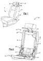
- FIG. 1is a perspective view of a vehicle seat assembly having a seat back.
- FIG. 2is a fragmentary perspective view of the seat back shown in FIG. 1 .
- FIGS. 3 a and 3 bare a perspective view of a head restraint arrangement having a headrest assembly.
- FIG. 4is a side view of a guide and headrest support of the headrest assembly shown in FIGS. 3 a and 3 b.
- FIG. 5is a fragmentary perspective view of another embodiment of a head restraint arrangement.
- FIG. 6is a section view of an embodiment of the headrest assembly having a tension spring.
- the vehicle seat assembly 10includes a seat bottom 12 and a seat back 14 .
- the vehicle seat assembly 10may be disposed in any suitable seating location of the vehicle.
- the vehicle seat assembly 10may be a front seat or may be disposed behind the front seat, such as in a second or third seating row of the vehicle.
- the seat back 14may be pivotally connected to the seat bottom 12 with one or more pivot mechanisms 16 .
- a pivot mechanism 16may be disposed on opposite sides the vehicle seat assembly 10 to allow the seat back 14 to pivot with respect to the seat bottom 12 .
- the seat bottom 12may be attached to a vehicle floor and/or to seat adjuster mechanisms 18 that enable lateral and/or vertical movement of the seat bottom 12 with respect to the vehicle floor.
- the seat back 14includes a frame 20 and a head restraint arrangement 22 .
- the frame 20may have any suitable configuration.
- the frame 20includes first and second side supports 30 , 32 and first and second cross members 34 , 36 .
- the first and second cross members 34 , 36extend laterally to connect the first and second side supports 30 , 32 .
- the side supports 30 , 32 and cross members 34 , 36may be separate components that are joined in any suitable manner, such as by welding, fasteners, or an adhesive.
- the side supports 30 , 32 and cross members 34 , 36 or any combinations thereofmay be integrally formed.
- the head restraint arrangement 22includes one or more headrest supports 40 and a head restraint or headrest assembly 42 .
- the headrest assembly 42is adapted to move between an extended position shown in phantom lines in FIG. 1 and a retracted position shown in solid lines in which the headrest assembly 42 is disposed proximate or closer to the seat back 14 .
- the headrest assembly 42may be selectively positioned between the extended and retracted positions as discussed in more detail below.
- the headrest support 40may have any suitable configuration. In the embodiment shown in FIG. 2 , two headrest supports 40 are provided. Alternatively, the headrest supports 40 may be coupled in a generally U-shaped arrangement.
- the headrest support 40may be made of any suitable material, such as a metal, and may have a tubular configuration.
- Each headrest support 40may include a lower portion 44 and a upper portion 46 .
- the lower and upper portions 44 , 46 as shownare generally linear and are angled relative to each other.
- the lower and upper portions 44 , 46may be coaxially formed or may be non-linear.
- the lower and upper portions 44 , 46may be integrally formed or may be separate components assembled in any suitable manner, such as by welding, fasteners, or an adhesive.
- the lower portion 44is fixedly positioned relative to the seat back 14 .
- the lower portion 44may be secured to a portion of the vehicle seat assembly 10 in any suitable manner, such as by attaching the lower portion 44 to part of the frame 20 .
- the lower portion 44is secured to the first cross member 32 .
- an intermediate componentsuch as a bracket or sleeve, may be used to couple the lower portion 44 to a portion of the vehicle seat assembly 10 .
- the upper portion 46is shown in more detail.
- the upper portion 46is adapted to support the headrest assembly 42 and may include an end 48 and one or more notches 50 .
- the notches 50may be spaced apart in a direction extending along a center axis 52 of the upper portion 46 .
- the notches 50may be disposed generally parallel to each other.
- the notches 50may have any suitable configuration.
- each notch 50has a generally triangular configuration that includes an upper surface 54 and a lower surface 56 .
- the upper and lower surfaces 54 , 56may be configured to permit the headrest assembly 42 to move toward the extended position and to inhibit movement of the headrest assembly 42 toward the retracted position as described in more detail below.
- the lower surface 56may be disposed generally perpendicular to the center axis 52 to help inhibit movement toward the retracted position.
- the upper surface 54may be disposed more parallel to the center axis 52 than the lower surface 56 and may be the longer than lower surface 56 .
- the headrest assembly 42may include a headrest frame 60 , a cushion assembly 62 , one or more guides 64 , one or more springs 66 , and one or more latching members 68 .
- the headrest frame 60may be made of any suitable material, such as a polymeric material or a metal.
- the headrest frame 60may have any suitable configuration and may include one or more recesses 70 .
- the headrest frame 60includes two recesses 70 .
- Each recess 70includes an opening 72 oriented toward the seat back 14 and an end surface 74 disposed opposite the opening 72 .
- Each recess 70is adapted to receive at least part of the upper portion 46 of an associated headrest support 40 .
- each recess 70may receive a guide 64 and a spring 66 as described in more detail below.
- the cushion assembly 62may be disposed proximate the headrest frame 60 .
- the cushion assembly 62includes a cushion 76 disposed proximate the headrest frame 60 and a trim panel 78 disposed proximate an exterior surface of the cushion 76 .
- the cushion 76 and trim cover 78may be made of any suitable material.
- the cushion 76may be made of a foam material while the trim cover 78 may be made of cloth, leather, or a polymeric material like vinyl.
- the guide 64is at least partially disposed in the recess 70 of the headrest frame 60 and is adapted to receive at least a portion of the headrest support 40 .
- the guide 64may be made of any suitable material, such as a polymeric material or a metal, and may have any suitable configuration.
- the guide 64has a tubular configuration and includes inlet end 80 , a distal end 82 , and a side opening 84 .
- the inlet end 80is disposed near the opening 72 of the headrest frame 60 .
- the distal end 82is disposed within the recess 70 between the opening 72 and the end surface 74 .
- the side opening 84is disposed between the inlet and distal ends 80 , 82 .
- the latching member 68is adapted to selectively engage a notch 50 to inhibit movement of the headrest assembly 42 toward the retracted position.
- the latching member 68may have any suitable configuration and may be disposed in any suitable location.
- the latching member 68is configured as a spring clip and is disposed proximate the guide 64 . More specifically, the latching member 68 is generally U-shaped and includes a first end 90 , a second end 92 , and a contact portion 94 disposed between the first and second ends 90 , 92 .
- the contact portion 94may extend through the side opening 84 of the guide 64 and may be angled toward the headrest support 22 .
- the latching member 68may be attached to another component of the headrest assembly 42 .
- the spring 66is provided to bias the headrest assembly 22 toward the retracted position.
- the spring 66may be of any suitable type and may have any suitable configuration.
- the spring 66is a compression spring and has a first end 100 that is connected to the upper portion 46 and a second end 102 that is disposed proximate the guide 64 . More particularly, the second end 102 may be disposed proximate the distal end 82 of the guide 64 or may be secured to the guide 64 between the distal end 82 and side opening 84 if sufficient clearance is provided between the recess 70 and the guide 64 .
- the spring 66 ′is a tension spring and has a first end 100 ′ and a second end 102 ′.
- the first end 100 ′is disposed proximate the end surface 74 of the recess 70 .
- the second end 102 ′is disposed proximate the upper portion 46 of the headrest support 40 . More particularly, the second end 102 ′ may be disposed proximate the end 48 of the upper portion 46 or may be secured to the upper portion 46 between the end 48 and the notches 50 to reduce package space.
- the springs 66 , 66 ′may be separated from the cushion assembly 62 by the headrest frame 66 , or another surface that defines a cavity wall.
- One or more cablesmay be provided to actuate the latching member 68 .
- a first cable 110 and a second cable 112are provided.
- the first cable 110includes a first end 114 and a second end 116 .
- the first end 114is disposed proximate the latching member 68 .
- the second end 116is disposed proximate a portion of vehicle seat assembly 10 that does not pivot with the seat back 14 , such as the seat bottom 12 or a portion of the pivot mechanism 16 disposed proximate the seat bottom 12 .
- the first cable 110may be routed through a headrest support 40 to help protect the first cable 110 and no interfere with movement of the headrest assembly 42 .
- the first cable 110may be secured to a portion of the seat back 14 , such as the frame 20 , with a retention clip or in any suitable manner.
- the second cable 112is provided to connect the latching members 68 associated with each headrest support 40 .
- the second cable 112may be omitted if a single latch mechanism is provided.
- the second cable 112may be disposed in any suitable location in the headrest assembly 42 , such as adjacent to or within the headrest frame 60 .
- the first and second cables 110 , 112may be integrally formed.
- a release mechanism 120may be provided to permit manual actuation of the latching member 68 .
- the release mechanism 120may have any suitable configuration, such as a button, lever, linkage, or wedge.
- the release mechanism 120may be disposed in any suitable location, such as proximate an exterior surface of the cushion 76 and/or trim panel 78 to facilitate ease-of-use.
- the release mechanism 120includes a release button 122 , a release rod 124 , and a reset spring 126 .
- the release button 122is configured to actuate a release rod 124 .
- the release rod 124may be pivotally connected to the guides 64 .
- a reset spring 126may be attached to the release rod 124 at a first end and attached to a cover 128 disposed proximate the headrest assembly 42 at a second end.
- the release spring 126may exert a biasing force to actuate the release rod 124 toward the seat back 14 .
- the release rod 124is configured to move the latching member 68 away from the headrest support 40 when the release button 122 is pressed.
- a cavitymay be provided proximate at least a portion of the release mechanism 120 to facilitate movement of the release rod 124 and/or release spring 126 .
- the headrest assembly 42may be automatically actuated toward the retracted position when the seat back 14 is folded relative to the seat bottom 12 .
- the latching member 68may engage a notch 50 .
- Folding of the seat back 14causes the first and second cables 110 , 112 to move.
- the first and second cables 110 , 112then pull on their associated latching members 68 , causing the latching members 68 to disengage from their respective notches.
- the headrest assembly 42is then free to move toward the retracted position in response to the biasing force exerted by the spring 66 , 66 ′.
- unfolding of the seat back 14 toward an upright positionreleases tension on the first and second cables 110 , 112 , thereby allowing the latching member 68 to engage the headrest support 40 and/or a notch 50 .
- the headrest assembly 42may then be manually actuated toward the extended position by exerting force on the headrest assembly 42 in a direction extending away from the seat back 14 . Moreover, the headrest assembly 42 may be selectively positioned between the retracted and extended positions by moving the headrest assembly 42 to engage a desired notch 50 .
- the configuration of the notchesfacilitates manual actuation of the headrest assembly 42 toward the extended position, while inhibiting movement toward the retracted position when the latching member 68 is extended.
- the present inventionallows a headrest assembly to be automatically retracted when a vehicle seat is folded or folded and tumbled in the case of a storable vehicle seat assembly.
- Automatic retractionis desirable since it allows the overall height of the seat back to be reduced without manual intervention, thereby reducing the likelihood of interference between the headrest assembly and another vehicle component, such as an instrument panel, a seat disposed in front of the vehicle seat assembly, or vehicle floor.
- the present inventionimproves ease of use and enhances customer satisfaction.
- automatic retractionis desirable in meeting manufacturer and/or government specifications, such as Federal Motor Vehicle Safety Specification 202A (FMVSS 202A).
- FMVSS 202AFederal Motor Vehicle Safety Specification 202A
- the manual adjustment capabilities of the present inventionallow a headrest arrangement to be selectively positioned to improve visibility and to provide positioning tailored to a vehicle occupant.
Landscapes
- Engineering & Computer Science (AREA)
- Aviation & Aerospace Engineering (AREA)
- Transportation (AREA)
- Mechanical Engineering (AREA)
- Seats For Vehicles (AREA)
Abstract
Description
Claims (20)
Priority Applications (3)
| Application Number | Priority Date | Filing Date | Title |
|---|---|---|---|
| US11/071,355US7506936B2 (en) | 2005-03-03 | 2005-03-03 | Moveable headrest assembly for a vehicle seat |
| GB0603818AGB2423708B (en) | 2005-03-03 | 2006-02-27 | Moveable headrest assembly for a vehicle seat |
| DE102006009712ADE102006009712B4 (en) | 2005-03-03 | 2006-03-02 | Vehicle seat with a movable headrest device |
Applications Claiming Priority (1)
| Application Number | Priority Date | Filing Date | Title |
|---|---|---|---|
| US11/071,355US7506936B2 (en) | 2005-03-03 | 2005-03-03 | Moveable headrest assembly for a vehicle seat |
Publications (2)
| Publication Number | Publication Date |
|---|---|
| US20060197366A1 US20060197366A1 (en) | 2006-09-07 |
| US7506936B2true US7506936B2 (en) | 2009-03-24 |
Family
ID=36178776
Family Applications (1)
| Application Number | Title | Priority Date | Filing Date |
|---|---|---|---|
| US11/071,355Expired - Fee RelatedUS7506936B2 (en) | 2005-03-03 | 2005-03-03 | Moveable headrest assembly for a vehicle seat |
Country Status (3)
| Country | Link |
|---|---|
| US (1) | US7506936B2 (en) |
| DE (1) | DE102006009712B4 (en) |
| GB (1) | GB2423708B (en) |
Cited By (5)
| Publication number | Priority date | Publication date | Assignee | Title |
|---|---|---|---|---|
| US20120148342A1 (en)* | 2010-03-10 | 2012-06-14 | Wanke Juergen | Headrest socket for accommodating a headrest rod |
| US20130015694A1 (en)* | 2011-07-13 | 2013-01-17 | Franco Tosco | Seat backrest for a motor vehicle |
| US8939513B2 (en) | 2009-05-13 | 2015-01-27 | Johnson Controls Technology Company | Rotating head rests |
| CN106945578A (en)* | 2015-12-19 | 2017-07-14 | 通用汽车环球科技运作有限责任公司 | Head rest device no for motor vehicle |
| US11142108B2 (en) | 2018-04-20 | 2021-10-12 | Daimay North America Automotive, Inc. | Bushing arrangement for headrest assembly |
Families Citing this family (12)
| Publication number | Priority date | Publication date | Assignee | Title |
|---|---|---|---|---|
| US20080100118A1 (en)* | 2006-10-27 | 2008-05-01 | Lear Corporation | Dynamic headrest |
| DE102006061638B4 (en)* | 2006-12-27 | 2010-08-05 | Lear Corp., Southfield | Vehicle seat assembly for supporting an occupant |
| US8276983B2 (en)* | 2007-12-11 | 2012-10-02 | Magna Seating Inc. | Manual retracting head restraint |
| US8616625B2 (en) | 2008-05-23 | 2013-12-31 | Johnson Controls Technology Company | Seat headrest |
| CN102686447B (en)* | 2010-01-18 | 2015-04-01 | 李尔公司 | Seat assembly having a cross member |
| US8876211B2 (en) | 2010-06-08 | 2014-11-04 | Lear Corporation | Seat assembly having a guide bushing |
| DE102011010232B4 (en)* | 2011-02-03 | 2013-01-17 | Audi Ag | Device for adjusting a headrest |
| WO2014033965A1 (en)* | 2012-09-03 | 2014-03-06 | テイ・エス テック株式会社 | Vehicle seat, and seat frame for vehicle seat |
| DE102015100752A1 (en)* | 2015-01-20 | 2016-07-21 | Illinois Tool Works Inc. | Device for variably fixing a headrest to a vehicle seat |
| WO2017057687A1 (en)* | 2015-09-30 | 2017-04-06 | 東海化成工業株式会社 | Stay for headrest |
| CN105835737B (en)* | 2016-05-20 | 2018-07-27 | 神龙汽车有限公司 | It is electrically adjusted the seat of height of headrest |
| DE102016013721A1 (en)* | 2016-11-17 | 2018-05-17 | Grammer Ag | Spring, use of a plastic tube as a spring and equipment part of a vehicle interior |
Citations (45)
| Publication number | Priority date | Publication date | Assignee | Title |
|---|---|---|---|---|
| US3563602A (en)* | 1967-10-04 | 1971-02-16 | Toyota Motor Co Ltd | Adjustable headrest for vehicle seat |
| US4222608A (en)* | 1977-12-30 | 1980-09-16 | Nissan Motor Company, Limited | Control system for adjustable head restraint on automotive seat |
| US4483565A (en)* | 1981-06-22 | 1984-11-20 | Ikeda Bussan Co., Ltd. | Head rest stay retaining device |
| US4545618A (en)* | 1984-02-22 | 1985-10-08 | Tachikawa Spring Co., Ltd. | Head-rest device |
| US4568123A (en)* | 1983-08-02 | 1986-02-04 | Tachikawa Spring Co., Ltd. | Head-rest vertical adjustment device |
| US4577904A (en)* | 1983-01-14 | 1986-03-25 | Itw Ateco Gmbh | Guiding sleeve for head rests at vehicle seats |
| US4604777A (en)* | 1982-08-20 | 1986-08-12 | Itw Limited | Spring retainers |
| US4657425A (en)* | 1985-02-14 | 1987-04-14 | Nifco, Inc. | Device for locking rod against movement in extending and contracting directions |
| US4657297A (en)* | 1985-04-25 | 1987-04-14 | Mazda Motor Corporation | Rear seat apparatus for automobile |
| US4765683A (en)* | 1985-11-26 | 1988-08-23 | Aisin Seiki Kabushiki Kaisha | Headrest apparatus |
| DE3843616A1 (en)* | 1988-12-23 | 1990-06-28 | Bayerische Motoren Werke Ag | Seat, in particular motor-vehicle seat |
| US5156440A (en)* | 1992-04-06 | 1992-10-20 | Hoover Universal, Inc. | Head restraint adjustment mechanism |
| US5529379A (en)* | 1994-03-19 | 1996-06-25 | Itw-Ateco Gmbh | Guiding sleeve for the headrests in seats of vehicles |
| US5711579A (en)* | 1995-06-28 | 1998-01-27 | Volkswagen Ag | Locking arrangement for a head restraint |
| GB2318285A (en) | 1996-10-17 | 1998-04-22 | Johnson Controls Automotive Uk | Vehicle seat having a retractable head restraint |
| US5823623A (en)* | 1996-03-30 | 1998-10-20 | Itw-Ateco Gmbh | Guide sleeve for neck rests on vehicle seats |
| US5860703A (en)* | 1996-07-31 | 1999-01-19 | Bertrand Faure Equipements S.A. | Vehicle seat including a headrest, and a headrest for a vehicle seat |
| DE19730911A1 (en) | 1997-07-18 | 1999-01-21 | Grammer Ag | Adjustable headrest for vehicle seat |
| US5895094A (en)* | 1996-04-08 | 1999-04-20 | Aisin Seiki Kabushiki Kaisha | Headrest apparatus for vehicle seat |
| US5918940A (en)* | 1996-06-26 | 1999-07-06 | Aisin Seiki Kabushiki Kaisha | Seat having an adjusting mechanism for adjusting height of head rest |
| US6012777A (en)* | 1997-04-29 | 2000-01-11 | Grammer Automotive Gmbh | Mount for motor-vehicle headrest |
| DE19832902A1 (en) | 1998-07-22 | 2000-01-27 | Grammer Ag | Seat for motor vehicle has headrest which with seat back in sitting position occupies highly set active position, and in forwards folded access position of seat back is adjusted to lowered position by pull cable |
| US6062645A (en)* | 1998-12-14 | 2000-05-16 | Del-Met Corporation | Headrest support assembly |
| US6074011A (en) | 1998-03-16 | 2000-06-13 | Johnson Controls Technology Company | Automatic retractable head restraint |
| US6099077A (en)* | 1998-10-27 | 2000-08-08 | Centura Group, Inc. | Head restraint assembly for motor vehicle |
| DE10035972A1 (en) | 1999-07-30 | 2001-02-22 | Faure Bertrand Equipements Sa | Improved headrest and seat provided with this headrest |
| US20010002764A1 (en) | 1999-12-01 | 2001-06-07 | Harald Fischer | Mechanical headrest retraction with memory effect with a seat for a means of transport |
| US20010013718A1 (en)* | 2000-02-10 | 2001-08-16 | Itw Automotive Products Gmbh & Co. Kg | Mechanical neck rest retraction device with a memory function |
| DE10043923A1 (en) | 2000-09-06 | 2002-04-04 | Keiper Gmbh & Co | Car seat has reclining back rest with separate head rest attached to mounting which is normally locked in raised position, but is biased towards position where it fits against top of the back rest by springs |
| US6454356B1 (en)* | 1998-08-25 | 2002-09-24 | Nihon Technica Co., Ltd. | Head rest support |
| US20030222492A1 (en)* | 2002-05-31 | 2003-12-04 | Tachi-S Co., Ltd | Locking/unlocking mechanism for headrest |
| US20030222491A1 (en)* | 2002-05-29 | 2003-12-04 | Centura Group, Inc. | Head restraint assembly for motor vehicle |
| US20030222493A1 (en)* | 2002-05-31 | 2003-12-04 | Tachi-S Co., Ltd. | Locking/unlocking mechanism for headrest |
| US6709051B2 (en)* | 2002-05-15 | 2004-03-23 | Daimlerchrysler Corporation | Bar actuator for retractable headrest |
| US6742846B1 (en)* | 2003-03-12 | 2004-06-01 | Troy Allen Isaacson | Modified head restraint assembly for motor vehicle seats |
| US6761409B2 (en)* | 2002-05-03 | 2004-07-13 | John R. Ford | Head restraint guide sleeve |
| US20050082893A1 (en)* | 2003-10-17 | 2005-04-21 | Delta Kogyo Co., Ltd. | Headrest lock structure with lock slots, method for forming lock slots in headrest pole and method for producing headrest pole |
| US6969118B2 (en)* | 2003-10-14 | 2005-11-29 | Nihon Technica Co., Ltd. | Headrest support structure |
| US20060108851A1 (en)* | 2004-11-22 | 2006-05-25 | Tachi-S Co. Ltd. | Headrest device for vehicle seat |
| US7059681B2 (en)* | 2004-01-29 | 2006-06-13 | Tachi-S Co., Ltd. | Headrest for vehicle seat |
| US7108327B2 (en)* | 2004-09-23 | 2006-09-19 | Lear Corporation | Adjustable head restraint guide |
| US7121625B2 (en)* | 2002-12-30 | 2006-10-17 | Lear Corporation | Headrest mechanism |
| US7140687B2 (en)* | 2004-11-18 | 2006-11-28 | Fisher Dynamics Corporation | Spring-loaded headrest |
| US7159946B2 (en)* | 2004-06-17 | 2007-01-09 | Illinois Tool Worlk Inc | Headrest guide button assembly |
| US20070145803A1 (en)* | 2003-07-15 | 2007-06-28 | Schukra Geratebau Ag | Adjuster of the vertical adjustment of a head restraint |
Family Cites Families (1)
| Publication number | Priority date | Publication date | Assignee | Title |
|---|---|---|---|---|
| WO2000035707A1 (en)* | 1998-12-14 | 2000-06-22 | Lear Corporation | Vehicle pivotal headrest |
- 2005
- 2005-03-03USUS11/071,355patent/US7506936B2/ennot_activeExpired - Fee Related
- 2006
- 2006-02-27GBGB0603818Apatent/GB2423708B/ennot_activeExpired - Fee Related
- 2006-03-02DEDE102006009712Apatent/DE102006009712B4/ennot_activeExpired - Fee Related
Patent Citations (47)
| Publication number | Priority date | Publication date | Assignee | Title |
|---|---|---|---|---|
| US3563602A (en)* | 1967-10-04 | 1971-02-16 | Toyota Motor Co Ltd | Adjustable headrest for vehicle seat |
| US4222608A (en)* | 1977-12-30 | 1980-09-16 | Nissan Motor Company, Limited | Control system for adjustable head restraint on automotive seat |
| US4483565A (en)* | 1981-06-22 | 1984-11-20 | Ikeda Bussan Co., Ltd. | Head rest stay retaining device |
| US4604777A (en)* | 1982-08-20 | 1986-08-12 | Itw Limited | Spring retainers |
| US4577904A (en)* | 1983-01-14 | 1986-03-25 | Itw Ateco Gmbh | Guiding sleeve for head rests at vehicle seats |
| US4568123A (en)* | 1983-08-02 | 1986-02-04 | Tachikawa Spring Co., Ltd. | Head-rest vertical adjustment device |
| US4545618A (en)* | 1984-02-22 | 1985-10-08 | Tachikawa Spring Co., Ltd. | Head-rest device |
| US4657425A (en)* | 1985-02-14 | 1987-04-14 | Nifco, Inc. | Device for locking rod against movement in extending and contracting directions |
| US4657297A (en)* | 1985-04-25 | 1987-04-14 | Mazda Motor Corporation | Rear seat apparatus for automobile |
| US4765683A (en)* | 1985-11-26 | 1988-08-23 | Aisin Seiki Kabushiki Kaisha | Headrest apparatus |
| DE3843616A1 (en)* | 1988-12-23 | 1990-06-28 | Bayerische Motoren Werke Ag | Seat, in particular motor-vehicle seat |
| US5156440A (en)* | 1992-04-06 | 1992-10-20 | Hoover Universal, Inc. | Head restraint adjustment mechanism |
| US5529379A (en)* | 1994-03-19 | 1996-06-25 | Itw-Ateco Gmbh | Guiding sleeve for the headrests in seats of vehicles |
| US5711579A (en)* | 1995-06-28 | 1998-01-27 | Volkswagen Ag | Locking arrangement for a head restraint |
| US5823623A (en)* | 1996-03-30 | 1998-10-20 | Itw-Ateco Gmbh | Guide sleeve for neck rests on vehicle seats |
| US5895094A (en)* | 1996-04-08 | 1999-04-20 | Aisin Seiki Kabushiki Kaisha | Headrest apparatus for vehicle seat |
| US5918940A (en)* | 1996-06-26 | 1999-07-06 | Aisin Seiki Kabushiki Kaisha | Seat having an adjusting mechanism for adjusting height of head rest |
| US5860703A (en)* | 1996-07-31 | 1999-01-19 | Bertrand Faure Equipements S.A. | Vehicle seat including a headrest, and a headrest for a vehicle seat |
| GB2318285A (en) | 1996-10-17 | 1998-04-22 | Johnson Controls Automotive Uk | Vehicle seat having a retractable head restraint |
| US6012777A (en)* | 1997-04-29 | 2000-01-11 | Grammer Automotive Gmbh | Mount for motor-vehicle headrest |
| DE19730911A1 (en) | 1997-07-18 | 1999-01-21 | Grammer Ag | Adjustable headrest for vehicle seat |
| US6074011A (en) | 1998-03-16 | 2000-06-13 | Johnson Controls Technology Company | Automatic retractable head restraint |
| DE69902150T2 (en) | 1998-03-16 | 2002-11-07 | Johnson Controls Technology Co., Plymouth | Automatically retractable headrest |
| DE19832902A1 (en) | 1998-07-22 | 2000-01-27 | Grammer Ag | Seat for motor vehicle has headrest which with seat back in sitting position occupies highly set active position, and in forwards folded access position of seat back is adjusted to lowered position by pull cable |
| US6454356B1 (en)* | 1998-08-25 | 2002-09-24 | Nihon Technica Co., Ltd. | Head rest support |
| US6099077A (en)* | 1998-10-27 | 2000-08-08 | Centura Group, Inc. | Head restraint assembly for motor vehicle |
| US6062645A (en)* | 1998-12-14 | 2000-05-16 | Del-Met Corporation | Headrest support assembly |
| DE10035972A1 (en) | 1999-07-30 | 2001-02-22 | Faure Bertrand Equipements Sa | Improved headrest and seat provided with this headrest |
| US6390558B2 (en)* | 1999-12-01 | 2002-05-21 | Lear Corporation | Seat for a means of transport |
| US20010002764A1 (en) | 1999-12-01 | 2001-06-07 | Harald Fischer | Mechanical headrest retraction with memory effect with a seat for a means of transport |
| US20010013718A1 (en)* | 2000-02-10 | 2001-08-16 | Itw Automotive Products Gmbh & Co. Kg | Mechanical neck rest retraction device with a memory function |
| DE10043923A1 (en) | 2000-09-06 | 2002-04-04 | Keiper Gmbh & Co | Car seat has reclining back rest with separate head rest attached to mounting which is normally locked in raised position, but is biased towards position where it fits against top of the back rest by springs |
| US6761409B2 (en)* | 2002-05-03 | 2004-07-13 | John R. Ford | Head restraint guide sleeve |
| US6709051B2 (en)* | 2002-05-15 | 2004-03-23 | Daimlerchrysler Corporation | Bar actuator for retractable headrest |
| US20030222491A1 (en)* | 2002-05-29 | 2003-12-04 | Centura Group, Inc. | Head restraint assembly for motor vehicle |
| US20030222492A1 (en)* | 2002-05-31 | 2003-12-04 | Tachi-S Co., Ltd | Locking/unlocking mechanism for headrest |
| US20030222493A1 (en)* | 2002-05-31 | 2003-12-04 | Tachi-S Co., Ltd. | Locking/unlocking mechanism for headrest |
| US7121625B2 (en)* | 2002-12-30 | 2006-10-17 | Lear Corporation | Headrest mechanism |
| US6742846B1 (en)* | 2003-03-12 | 2004-06-01 | Troy Allen Isaacson | Modified head restraint assembly for motor vehicle seats |
| US20070145803A1 (en)* | 2003-07-15 | 2007-06-28 | Schukra Geratebau Ag | Adjuster of the vertical adjustment of a head restraint |
| US6969118B2 (en)* | 2003-10-14 | 2005-11-29 | Nihon Technica Co., Ltd. | Headrest support structure |
| US20050082893A1 (en)* | 2003-10-17 | 2005-04-21 | Delta Kogyo Co., Ltd. | Headrest lock structure with lock slots, method for forming lock slots in headrest pole and method for producing headrest pole |
| US7059681B2 (en)* | 2004-01-29 | 2006-06-13 | Tachi-S Co., Ltd. | Headrest for vehicle seat |
| US7159946B2 (en)* | 2004-06-17 | 2007-01-09 | Illinois Tool Worlk Inc | Headrest guide button assembly |
| US7108327B2 (en)* | 2004-09-23 | 2006-09-19 | Lear Corporation | Adjustable head restraint guide |
| US7140687B2 (en)* | 2004-11-18 | 2006-11-28 | Fisher Dynamics Corporation | Spring-loaded headrest |
| US20060108851A1 (en)* | 2004-11-22 | 2006-05-25 | Tachi-S Co. Ltd. | Headrest device for vehicle seat |
Cited By (8)
| Publication number | Priority date | Publication date | Assignee | Title |
|---|---|---|---|---|
| US8939513B2 (en) | 2009-05-13 | 2015-01-27 | Johnson Controls Technology Company | Rotating head rests |
| US20120148342A1 (en)* | 2010-03-10 | 2012-06-14 | Wanke Juergen | Headrest socket for accommodating a headrest rod |
| US9004803B2 (en)* | 2010-03-10 | 2015-04-14 | Faurecia Autositze Gmbh | Headrest socket for accommodating a headrest rod |
| US20130015694A1 (en)* | 2011-07-13 | 2013-01-17 | Franco Tosco | Seat backrest for a motor vehicle |
| US9067520B2 (en)* | 2011-07-13 | 2015-06-30 | C.R.F. Societa' Consortile Per Azioni | Seat backrest for a motor vehicle |
| CN106945578A (en)* | 2015-12-19 | 2017-07-14 | 通用汽车环球科技运作有限责任公司 | Head rest device no for motor vehicle |
| US10017084B2 (en)* | 2015-12-19 | 2018-07-10 | GM Global Technology Operations LLC | Head rest for a motor vehicle |
| US11142108B2 (en) | 2018-04-20 | 2021-10-12 | Daimay North America Automotive, Inc. | Bushing arrangement for headrest assembly |
Also Published As
| Publication number | Publication date |
|---|---|
| DE102006009712B4 (en) | 2010-06-10 |
| US20060197366A1 (en) | 2006-09-07 |
| GB0603818D0 (en) | 2006-04-05 |
| DE102006009712A1 (en) | 2006-09-07 |
| GB2423708B (en) | 2008-04-09 |
| GB2423708A (en) | 2006-09-06 |
Similar Documents
| Publication | Publication Date | Title |
|---|---|---|
| GB2423708A (en) | Adjustable head rest assembly | |
| US6192565B1 (en) | Automotive seat assembly having a rectractable headrest | |
| US7871129B2 (en) | Seat assembly having an adjustable head restraint assembly | |
| CN110539675B (en) | Headrest and vehicle seat | |
| US6749256B1 (en) | Vehicle seat having a movable head restraint | |
| CA2664954C (en) | Fold flat seat with rearward folding motion | |
| US7992913B2 (en) | Fold flat seat assembly | |
| US8763538B2 (en) | Folding table | |
| US8465098B2 (en) | Adjustable head restraint assembly for vehicle seats | |
| US8474777B2 (en) | Seat slide apparatus for vehicle | |
| US9789789B2 (en) | Vehicular seat | |
| US20110095592A1 (en) | Folding Vehicle Head Restraint Assembly | |
| US11208019B2 (en) | Headrest assembly | |
| KR20110081895A (en) | Folding seat | |
| JP2007503925A (en) | Ergonomic support device and method for centering an occupant | |
| US9145073B2 (en) | Collapsible bolster cushion | |
| US20180319293A1 (en) | Stowable Vehicle Seat Assembly Having a Pivot Link | |
| US20170158100A1 (en) | Multi-directional translational head restraint | |
| JP6236233B2 (en) | Vehicle seat | |
| JP2001163101A (en) | Headrest structure of vehicle seat | |
| US11117497B2 (en) | Vehicle seat having a displaceable upper backrest part | |
| JP6663557B2 (en) | Vehicle seat frame structure and vehicle seat using the same | |
| US20210387554A1 (en) | Headrest assembly configured to resist vibration | |
| JP6643713B2 (en) | Vehicle seat reclining device | |
| KR101972509B1 (en) | Controlling apparatus of headrest |
Legal Events
| Date | Code | Title | Description |
|---|---|---|---|
| AS | Assignment | Owner name:LEAR CORPORATION, MICHIGAN Free format text:ASSIGNMENT OF ASSIGNORS INTEREST;ASSIGNOR:SABERAN, MOHAMMAD;REEL/FRAME:016354/0534 Effective date:20050303 | |
| STCF | Information on status: patent grant | Free format text:PATENTED CASE | |
| AS | Assignment | Owner name:JPMORGAN CHASE BANK, N.A., AS ADMINISTRATIVE AGENT Free format text:GRANT OF FIRST LIEN SECURITY INTEREST IN PATENT RIGHTS;ASSIGNOR:LEAR CORPORATION;REEL/FRAME:023519/0267 Effective date:20091109 Owner name:JPMORGAN CHASE BANK, N.A., AS ADMINISTRATIVE AGENT Free format text:GRANT OF SECOND LIEN SECURITY INTEREST IN PATENT RIGHTS;ASSIGNOR:LEAR CORPORATION;REEL/FRAME:023519/0626 Effective date:20091109 | |
| FPAY | Fee payment | Year of fee payment:4 | |
| AS | Assignment | Owner name:JPMORGAN CAHSE BANK, N.A., AS AGENT, ILLINOIS Free format text:SECURITY INTEREST;ASSIGNOR:LEAR CORPORATION;REEL/FRAME:030076/0016 Effective date:20130130 Owner name:JPMORGAN CHASE BANK, N.A., AS AGENT, ILLINOIS Free format text:SECURITY INTEREST;ASSIGNOR:LEAR CORPORATION;REEL/FRAME:030076/0016 Effective date:20130130 | |
| AS | Assignment | Owner name:LEAR CORPORATION, MICHIGAN Free format text:RELEASE BY SECURED PARTY;ASSIGNOR:JPMORGAN CHASE BANK, N.A.;REEL/FRAME:032770/0843 Effective date:20100830 | |
| AS | Assignment | Owner name:LEAR CORPORATION, MICHIGAN Free format text:RELEASE BY SECURED PARTY;ASSIGNOR:JPMORGAN CHASE BANK, N.A., AS AGENT;REEL/FRAME:037701/0340 Effective date:20160104 Owner name:LEAR CORPORATION, MICHIGAN Free format text:RELEASE BY SECURED PARTY;ASSIGNOR:JPMORGAN CHASE BANK, N.A., AS AGENT;REEL/FRAME:037701/0180 Effective date:20160104 Owner name:LEAR CORPORATION, MICHIGAN Free format text:RELEASE BY SECURED PARTY;ASSIGNOR:JPMORGAN CHASE BANK, N.A., AS AGENT;REEL/FRAME:037701/0251 Effective date:20160104 | |
| AS | Assignment | Owner name:LEAR CORPORATION, MICHIGAN Free format text:RELEASE BY SECURED PARTY;ASSIGNOR:JPMORGAN CHASE BANK, N.A., AS AGENT;REEL/FRAME:037702/0911 Effective date:20160104 | |
| FPAY | Fee payment | Year of fee payment:8 | |
| FEPP | Fee payment procedure | Free format text:MAINTENANCE FEE REMINDER MAILED (ORIGINAL EVENT CODE: REM.); ENTITY STATUS OF PATENT OWNER: LARGE ENTITY | |
| LAPS | Lapse for failure to pay maintenance fees | Free format text:PATENT EXPIRED FOR FAILURE TO PAY MAINTENANCE FEES (ORIGINAL EVENT CODE: EXP.); ENTITY STATUS OF PATENT OWNER: LARGE ENTITY | |
| STCH | Information on status: patent discontinuation | Free format text:PATENT EXPIRED DUE TO NONPAYMENT OF MAINTENANCE FEES UNDER 37 CFR 1.362 | |
| FP | Lapsed due to failure to pay maintenance fee | Effective date:20210324 |