US7506846B2 - Foot for optical or photographic supports - Google Patents
Foot for optical or photographic supportsDownload PDFInfo
- Publication number
- US7506846B2 US7506846B2US10/539,142US53914204AUS7506846B2US 7506846 B2US7506846 B2US 7506846B2US 53914204 AUS53914204 AUS 53914204AUS 7506846 B2US7506846 B2US 7506846B2
- Authority
- US
- United States
- Prior art keywords
- sleeve
- foot
- rollers
- ring
- pair
- Prior art date
- Legal status (The legal status is an assumption and is not a legal conclusion. Google has not performed a legal analysis and makes no representation as to the accuracy of the status listed.)
- Expired - Lifetime, expires
Links
- 230000003287optical effectEffects0.000titleclaimsabstractdescription14
- 230000007246mechanismEffects0.000claimsabstractdescription26
- 238000005303weighingMethods0.000claimsdescription5
- 230000000903blocking effectEffects0.000description2
- 229910000838Al alloyInorganic materials0.000description1
- 239000003795chemical substances by applicationSubstances0.000description1
- 238000010276constructionMethods0.000description1
- 239000000428dustSubstances0.000description1
- 230000000694effectsEffects0.000description1
- 229910001234light alloyInorganic materials0.000description1
Images

Classifications
- F—MECHANICAL ENGINEERING; LIGHTING; HEATING; WEAPONS; BLASTING
- F16—ENGINEERING ELEMENTS AND UNITS; GENERAL MEASURES FOR PRODUCING AND MAINTAINING EFFECTIVE FUNCTIONING OF MACHINES OR INSTALLATIONS; THERMAL INSULATION IN GENERAL
- F16B—DEVICES FOR FASTENING OR SECURING CONSTRUCTIONAL ELEMENTS OR MACHINE PARTS TOGETHER, e.g. NAILS, BOLTS, CIRCLIPS, CLAMPS, CLIPS OR WEDGES; JOINTS OR JOINTING
- F16B7/00—Connections of rods or tubes, e.g. of non-circular section, mutually, including resilient connections
- F16B7/10—Telescoping systems
- F16B7/14—Telescoping systems locking in intermediate non-discrete positions
- F16B7/1409—Telescoping systems locking in intermediate non-discrete positions with balls or rollers urged by an axial displacement of a wedge or a conical member
- F—MECHANICAL ENGINEERING; LIGHTING; HEATING; WEAPONS; BLASTING
- F16—ENGINEERING ELEMENTS AND UNITS; GENERAL MEASURES FOR PRODUCING AND MAINTAINING EFFECTIVE FUNCTIONING OF MACHINES OR INSTALLATIONS; THERMAL INSULATION IN GENERAL
- F16M—FRAMES, CASINGS OR BEDS OF ENGINES, MACHINES OR APPARATUS, NOT SPECIFIC TO ENGINES, MACHINES OR APPARATUS PROVIDED FOR ELSEWHERE; STANDS; SUPPORTS
- F16M11/00—Stands or trestles as supports for apparatus or articles placed thereon ; Stands for scientific apparatus such as gravitational force meters
- F16M11/20—Undercarriages with or without wheels
- F16M11/24—Undercarriages with or without wheels changeable in height or length of legs, also for transport only, e.g. by means of tubes screwed into each other
- F16M11/26—Undercarriages with or without wheels changeable in height or length of legs, also for transport only, e.g. by means of tubes screwed into each other by telescoping, with or without folding
- F16M11/28—Undercarriages for supports with one single telescoping pillar
- F—MECHANICAL ENGINEERING; LIGHTING; HEATING; WEAPONS; BLASTING
- F16—ENGINEERING ELEMENTS AND UNITS; GENERAL MEASURES FOR PRODUCING AND MAINTAINING EFFECTIVE FUNCTIONING OF MACHINES OR INSTALLATIONS; THERMAL INSULATION IN GENERAL
- F16M—FRAMES, CASINGS OR BEDS OF ENGINES, MACHINES OR APPARATUS, NOT SPECIFIC TO ENGINES, MACHINES OR APPARATUS PROVIDED FOR ELSEWHERE; STANDS; SUPPORTS
- F16M11/00—Stands or trestles as supports for apparatus or articles placed thereon ; Stands for scientific apparatus such as gravitational force meters
- F16M11/20—Undercarriages with or without wheels
- F16M11/24—Undercarriages with or without wheels changeable in height or length of legs, also for transport only, e.g. by means of tubes screwed into each other
- F16M11/26—Undercarriages with or without wheels changeable in height or length of legs, also for transport only, e.g. by means of tubes screwed into each other by telescoping, with or without folding
- F16M11/32—Undercarriages for supports with three or more telescoping legs
- F—MECHANICAL ENGINEERING; LIGHTING; HEATING; WEAPONS; BLASTING
- F16—ENGINEERING ELEMENTS AND UNITS; GENERAL MEASURES FOR PRODUCING AND MAINTAINING EFFECTIVE FUNCTIONING OF MACHINES OR INSTALLATIONS; THERMAL INSULATION IN GENERAL
- F16M—FRAMES, CASINGS OR BEDS OF ENGINES, MACHINES OR APPARATUS, NOT SPECIFIC TO ENGINES, MACHINES OR APPARATUS PROVIDED FOR ELSEWHERE; STANDS; SUPPORTS
- F16M2200/00—Details of stands or supports
- F16M2200/02—Locking means
- F16M2200/025—Locking means for translational movement
- F16M2200/027—Locking means for translational movement by friction
- F—MECHANICAL ENGINEERING; LIGHTING; HEATING; WEAPONS; BLASTING
- F16—ENGINEERING ELEMENTS AND UNITS; GENERAL MEASURES FOR PRODUCING AND MAINTAINING EFFECTIVE FUNCTIONING OF MACHINES OR INSTALLATIONS; THERMAL INSULATION IN GENERAL
- F16M—FRAMES, CASINGS OR BEDS OF ENGINES, MACHINES OR APPARATUS, NOT SPECIFIC TO ENGINES, MACHINES OR APPARATUS PROVIDED FOR ELSEWHERE; STANDS; SUPPORTS
- F16M2200/00—Details of stands or supports
- F16M2200/08—Foot or support base
Definitions
- the present inventionrelates to a foot for optical or photographic supports.
- the footis suitable for the construction of monopod or pluripod supports, in particular so-called tripod supports.
- the telescopic membersbe provided with arrangements for relative locking that are suitable for increasing the locking action under load while ensuring easy unlocking when the work has been completed. It is also desired that it should be possible to activate the unlocking operation with a single control operation.
- feetalsowise known as legs in pluripod supports
- telescopic membersone of which has locking means of the type in the form of a ring of balls. Locking is effected by expansion of the ring of balls as a result of the relative movement between the balls and a frustoconical expander body.
- a first disadvantage of this type of footis encountered when, as is routine, the telescopic members are produced from a light alloy, for example aluminium alloy.
- the action of the expander bodyincreases under load, that is to say, the force with which the balls are pressed against the inner shell of the telescopic member in question increases in proportion to the load weighing on the foot, conditions may arise in which the radial expansion pressure of the ring is such as significantly to damage the inner shell of the telescopic member against which the balls press.
- Unlockingis effected by operating a rod which acts on a plate which holds the balls against the expander body.
- the mechanismis such that it is possible to control only one pair of telescopic members, which limits to an unacceptable extent the height of the foot in the extended condition.
- the problem on which the present invention is basedis to provide a foot for monopod or pluripod supports which are intended for optical equipment, including specifically photographic and/or cinematographic equipment, which foot is designed structurally and functionally to overcome all of the disadvantages discussed with reference to the mentioned prior art.
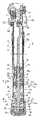
- FIG. 1is a view in longitudinal section of a foot produced in accordance with the present invention
- FIGS. 2 and 3are cross-sectional views taken at the location of the lines II-II and III-III in FIG. 1 .
- 1generally indicates a foot having at one axial end a mechanism 2 for articulation to a cross-member or the like (not shown) in order to form a pluripod support, for example a photographic tripod.
- the foot 1comprises three tubular telescopic members 3 , 4 , 5 , of increasing diameter, which are slidably insertable one inside the other in the contracted position of FIG. 1 and which are telescopically extendable one from the other in the required operative extension condition.
- the first tubular telescopic member 3that having the smallest diameter, has one end accommodated in a seat 7 of the mechanism 2 and has, inserted at the opposite end, a stopper 8 which has a central hole 9 and which, with a lip 10 thereof, abuts the free end of the first telescopic member.
- the stopper 8forms an engagement surface 10 a for a resilient means, such as a helical spring 11 , which in turn acts against a shoulder 12 of a sleeve 13 .
- the sleeve 13is tubular and extends beyond the free end of the first telescopic member, terminating in an appendage 14 having a ring 15 which holds a plate 16 of a cage 17 .
- the cage 17comprises a ring 19 to which are coupled legs 19 a which extend from the plate 16 and are spaced circumferentially with equal angular spacings.
- a ring of barrel rollers 20which are circumferentially equidistant and whose outer shell 21 has a curvature substantially identical to the curvature of the inner shell of the second telescopic member 4 .
- a large radial clearanceis present between the rollers, the inner shell of the second telescopic member and the sleeve and is partially occupied by the free end of an expander body in the form of a conical ring 22 which, at the opposite end, abuts the stopper 8 and is capable of being placed between the rollers and the sleeve in the manner explained hereinafter.
- What has been describedthus far constitutes a first expanding stop mechanism for blocking the relative telescoping between the first and second telescopic members, that is to say, between two adjacent telescopic members of a first pair of telescopic members.
- the second and third telescopic membersalso form a pair of telescopic members which are adjacent to one another, and a corresponding second expanding stop mechanism is provided which is substantially analogous to that described above, to the extent that analogous details are indicated by the same reference numerals supplemented by the index (′).
- the main difference between the first and second stop mechanismresides in the fact that the sleeve 13 ′ has a seat 25 for accommodating the appendage 14 of the first mechanism.
- the third telescopic memberis closed at one end by a cap 26 and has at the opposite end a dust-protecting means 27 for preventing dust and dirt from entering the inside of the foot 1 .
- a rod-shaped control 31extending axially in the foot 1 and operable from outside the foot by a push-button 32 by way of an angular guide 33 is provided for the release on command of the first stop mechanism.
- a spring 34is used to urge the push-button into a non-stressed state and a threaded grub screw 35 is used to adjust the clearance between the guide and the rod-shaped control.
- the rod-shaped control 31acts on the sleeve 13 by way of an enlarged portion 36 , extends through the sleeve with an extension 37 thereof and is capable of snap-engagement in the central seat 29 of the plug 28 , being held there by snap-engagement of the radial pins 30 in a circumferential groove 38 when the foot 1 is completely retracted ( FIG. 1 ). In that state, the extension 37 is accommodated in the axial hole of the sleeve 13 ′.
- the operation of the foot 1is as follows.
- the relative sliding between the telescopic members 3 , 4 , 5is blocked with a blocking action which increases in proportion to the load applied to the foot.
- the expander body 22Owing to the resilient preloading applied to the ring of rollers 20 by way of the plate 16 , the expander body 22 is initially positioned between the ring of rollers 20 and the sleeve 13 .
- the axial load applied to the foot in the direction of closing the sameis consistent with this positioning action generating greater pressure of the rollers against the inner shell of the telescopic member against which they bear.
- the wall of the telescopic member in questionis not, however, damaged, because the curvature of the rollers is substantially equal to that of the telescopic member and contact is distributed over a larger surface.
- the contact between the surface of the roller and the surface of the inner shell of the telescopic memberis a surface contact instead of a punctiform contact.
- the push-button 32is pressed in such a manner as to pivot the angular guide 33 and to move the rod-shaped control 31 axially.
- an action unlocking the first stop mechanismis exerted because the plate 16 is moved away from the conical ring 22 (expander body) by means of the movement imparted to the sleeve 13 by the enlarged portion 36 in opposition to the spring 11 , with a consequent release of the ring of rollers 20 .
- Thisenables the extension of the first telescopic member relative to the second to be adjusted as far as complete closure.
- the inventionthus solves the problem posed and obtains numerous advantages over conventional feet, including greater speed of opening and closing the tripod.
- simpler adjustment of the length of each single footis permitted thanks to the positioning of the control push-button in the vicinity of the cross-member.
- the inventionoffers the advantage of not having external members on the stop mechanism.
- the mechanismis more protected from the action of atmospheric agents and from jolts, and the undesired possibility that cables or belts (for example of photographic apparatus) may become entangled in external members is also prevented.
Landscapes
- Engineering & Computer Science (AREA)
- General Engineering & Computer Science (AREA)
- Mechanical Engineering (AREA)
- Accessories Of Cameras (AREA)
- Fishing Rods (AREA)
Abstract
Description
Claims (10)
Applications Claiming Priority (3)
| Application Number | Priority Date | Filing Date | Title |
|---|---|---|---|
| IT000020AITPD20030020A1 (en) | 2003-01-30 | 2003-01-30 | FOOT FOR OPTICAL OR PHOTOGRAPHIC SUPPORTS |
| ITPD2003A000020 | 2003-01-30 | ||
| PCT/EP2004/000448WO2004068024A1 (en) | 2003-01-30 | 2004-01-21 | A foot for optical or photographic supports |
Publications (2)
| Publication Number | Publication Date |
|---|---|
| US20060186286A1 US20060186286A1 (en) | 2006-08-24 |
| US7506846B2true US7506846B2 (en) | 2009-03-24 |
Family
ID=32800726
Family Applications (1)
| Application Number | Title | Priority Date | Filing Date |
|---|---|---|---|
| US10/539,142Expired - LifetimeUS7506846B2 (en) | 2003-01-30 | 2004-01-21 | Foot for optical or photographic supports |
Country Status (7)
| Country | Link |
|---|---|
| US (1) | US7506846B2 (en) |
| EP (1) | EP1592914B1 (en) |
| JP (1) | JP4404894B2 (en) |
| CN (1) | CN100424403C (en) |
| DE (1) | DE602004002457T2 (en) |
| IT (1) | ITPD20030020A1 (en) |
| WO (1) | WO2004068024A1 (en) |
Cited By (8)
| Publication number | Priority date | Publication date | Assignee | Title |
|---|---|---|---|---|
| US20100229679A1 (en)* | 2009-03-15 | 2010-09-16 | Lai Chui-Teng | Stepless positioning structure for telescopic tube |
| US7845602B1 (en) | 2006-02-09 | 2010-12-07 | Primos, Inc. | Telescoping support stand apparatus |
| US20110173867A1 (en)* | 2010-01-15 | 2011-07-21 | Desert Manufacturing, Llc | Adjustable support for firearms |
| US8146876B1 (en)* | 2006-02-09 | 2012-04-03 | Primos, Inc. | Telescoping support stand apparatus |
| US9903528B1 (en)* | 2014-09-22 | 2018-02-27 | Joshua Terry Hatch | Telescoping lock mechanism |
| US9933225B2 (en) | 2016-02-25 | 2018-04-03 | Ravin Crossbows, Llc | Bipod with a quick connect feature for standard rails |
| US20190003635A1 (en)* | 2017-06-30 | 2019-01-03 | Guangdong Sirui Optical Co., Ltd. | Tripod button mechanism and a tripod |
| US20230184372A1 (en)* | 2021-12-15 | 2023-06-15 | Bushnell Holdings, Inc. | Telescoping support stand apparatus |
Families Citing this family (6)
| Publication number | Priority date | Publication date | Assignee | Title |
|---|---|---|---|---|
| JP4547542B2 (en)* | 2007-12-28 | 2010-09-22 | 英也 大関 | Camera support |
| JP4696290B2 (en)* | 2008-09-17 | 2011-06-08 | 英也 大関 | Camera support |
| EP2233817A1 (en)* | 2009-03-27 | 2010-09-29 | König & Meyer GmbH & Co. KG | Supporting column, in particular music rest or microphone supporting column |
| CN103595841B (en)* | 2013-11-12 | 2015-11-25 | 胡海明 | Remote mobile phone is from taking the photograph device |
| CN108151583A (en)* | 2017-06-06 | 2018-06-12 | 上海飞米工业设计有限公司 | The adjustable support foot damped for the band of shotgun |
| CN119879009B (en)* | 2025-03-26 | 2025-06-24 | 成都理工大学 | A self-balancing and regulating soil quality detection device |
Citations (8)
| Publication number | Priority date | Publication date | Assignee | Title |
|---|---|---|---|---|
| DE592023C (en) | 1933-01-13 | 1934-01-31 | Johann Schiansky | Extension tube, especially for tripod feet |
| US2529861A (en)* | 1945-09-01 | 1950-11-14 | White S Dental Mfg Co | Adjustable seat supporting structure |
| DE1775404B1 (en) | 1968-08-07 | 1971-11-25 | Erna Klever Fa | Extension tube, especially for tripods or similar height-adjustable device stands or holders |
| US3807574A (en)* | 1972-07-28 | 1974-04-30 | Dynadesign Inc | Costumer |
| US4073456A (en)* | 1976-07-14 | 1978-02-14 | Alex D. Karapita | Suspension support |
| US4526334A (en)* | 1981-09-28 | 1985-07-02 | Martela Oy | Device for adjusting the height of desktop, chair or similar |
| US20020195411A1 (en) | 2001-06-19 | 2002-12-26 | Lin-Ho Liu | Structure of a tube rack with telescoping function |
| US7204466B2 (en)* | 2005-03-11 | 2007-04-17 | Wu-Hong Hsieh | Quick-acting telescopic tube |
Family Cites Families (2)
| Publication number | Priority date | Publication date | Assignee | Title |
|---|---|---|---|---|
| ITPD940140A1 (en)* | 1993-09-30 | 1996-01-27 | Manfrotto Lino & C Spa | EXTENDABLE AUCTION |
| GB9608945D0 (en)* | 1996-04-29 | 1996-07-03 | Vitec Group Plc | Improvements in or relating to extendible legs for stands or similar appliances |
- 2003
- 2003-01-30ITIT000020Apatent/ITPD20030020A1/enunknown
- 2004
- 2004-01-21USUS10/539,142patent/US7506846B2/ennot_activeExpired - Lifetime
- 2004-01-21DEDE602004002457Tpatent/DE602004002457T2/ennot_activeExpired - Lifetime
- 2004-01-21JPJP2006501569Apatent/JP4404894B2/ennot_activeExpired - Fee Related
- 2004-01-21CNCNB2004800033391Apatent/CN100424403C/ennot_activeExpired - Fee Related
- 2004-01-21EPEP04703778Apatent/EP1592914B1/ennot_activeExpired - Lifetime
- 2004-01-21WOPCT/EP2004/000448patent/WO2004068024A1/enactiveIP Right Grant
Patent Citations (8)
| Publication number | Priority date | Publication date | Assignee | Title |
|---|---|---|---|---|
| DE592023C (en) | 1933-01-13 | 1934-01-31 | Johann Schiansky | Extension tube, especially for tripod feet |
| US2529861A (en)* | 1945-09-01 | 1950-11-14 | White S Dental Mfg Co | Adjustable seat supporting structure |
| DE1775404B1 (en) | 1968-08-07 | 1971-11-25 | Erna Klever Fa | Extension tube, especially for tripods or similar height-adjustable device stands or holders |
| US3807574A (en)* | 1972-07-28 | 1974-04-30 | Dynadesign Inc | Costumer |
| US4073456A (en)* | 1976-07-14 | 1978-02-14 | Alex D. Karapita | Suspension support |
| US4526334A (en)* | 1981-09-28 | 1985-07-02 | Martela Oy | Device for adjusting the height of desktop, chair or similar |
| US20020195411A1 (en) | 2001-06-19 | 2002-12-26 | Lin-Ho Liu | Structure of a tube rack with telescoping function |
| US7204466B2 (en)* | 2005-03-11 | 2007-04-17 | Wu-Hong Hsieh | Quick-acting telescopic tube |
Cited By (17)
| Publication number | Priority date | Publication date | Assignee | Title |
|---|---|---|---|---|
| US9010710B1 (en) | 2006-02-09 | 2015-04-21 | Primos, Inc. | Telescoping support stand apparatus |
| US8146876B1 (en)* | 2006-02-09 | 2012-04-03 | Primos, Inc. | Telescoping support stand apparatus |
| US8256732B1 (en) | 2006-02-09 | 2012-09-04 | Primos, Inc. | Telescoping support stand apparatus |
| US8469326B1 (en) | 2006-02-09 | 2013-06-25 | Primos, Inc. | Telescoping support stand apparatus |
| US8714508B1 (en) | 2006-02-09 | 2014-05-06 | Primos, Inc. | Telescoping support stand apparatus |
| US8820693B1 (en)* | 2006-02-09 | 2014-09-02 | Primos, Inc. | Telescoping support stand apparatus |
| US7845602B1 (en) | 2006-02-09 | 2010-12-07 | Primos, Inc. | Telescoping support stand apparatus |
| US20100229679A1 (en)* | 2009-03-15 | 2010-09-16 | Lai Chui-Teng | Stepless positioning structure for telescopic tube |
| US20110173867A1 (en)* | 2010-01-15 | 2011-07-21 | Desert Manufacturing, Llc | Adjustable support for firearms |
| US9903528B1 (en)* | 2014-09-22 | 2018-02-27 | Joshua Terry Hatch | Telescoping lock mechanism |
| US10386011B2 (en)* | 2014-09-22 | 2019-08-20 | Joshua Terry Hatch | Telescoping lock mechanism |
| US11313509B2 (en) | 2014-09-22 | 2022-04-26 | Joshua Terry Hatch | Telescoping lock mechanism |
| US9933225B2 (en) | 2016-02-25 | 2018-04-03 | Ravin Crossbows, Llc | Bipod with a quick connect feature for standard rails |
| US20190003635A1 (en)* | 2017-06-30 | 2019-01-03 | Guangdong Sirui Optical Co., Ltd. | Tripod button mechanism and a tripod |
| US10612719B2 (en)* | 2017-06-30 | 2020-04-07 | Guangdong Sirui Optical Co., Ltd. | Tripod button mechanism and a tripod |
| US20230184372A1 (en)* | 2021-12-15 | 2023-06-15 | Bushnell Holdings, Inc. | Telescoping support stand apparatus |
| US12196359B2 (en)* | 2021-12-15 | 2025-01-14 | Bushnell Holdings, Inc. | Telescoping support stand apparatus |
Also Published As
| Publication number | Publication date |
|---|---|
| DE602004002457T2 (en) | 2007-09-20 |
| CN100424403C (en) | 2008-10-08 |
| EP1592914A1 (en) | 2005-11-09 |
| WO2004068024A1 (en) | 2004-08-12 |
| US20060186286A1 (en) | 2006-08-24 |
| JP2006516707A (en) | 2006-07-06 |
| CN1745272A (en) | 2006-03-08 |
| JP4404894B2 (en) | 2010-01-27 |
| EP1592914B1 (en) | 2006-09-20 |
| ITPD20030020A1 (en) | 2004-07-31 |
| DE602004002457D1 (en) | 2006-11-02 |
Similar Documents
| Publication | Publication Date | Title |
|---|---|---|
| US7506846B2 (en) | Foot for optical or photographic supports | |
| US6913231B2 (en) | Telescopic stand for optical or photographic apparatus and the like | |
| US7182303B2 (en) | Stabilizer with telescopic rods for tripods | |
| EP1966531B1 (en) | An adjustable telescopic support | |
| US2806723A (en) | Telescopic support device | |
| US4706916A (en) | Support stand with adjustable legs | |
| US20080283713A1 (en) | Support Particularly for Optical or Photographic Use | |
| US4531855A (en) | Adjustable arm | |
| ITPD20130154A1 (en) | SUPPORT FOR PHOTOGRAPHIC EQUIPMENT | |
| US10500891B2 (en) | Mechanical pencil | |
| US2838266A (en) | Adjustable strut | |
| US3338607A (en) | Extensible handle | |
| JP2003130017A (en) | Telescopic pipe | |
| US5708889A (en) | Device for adjusting the length of an extendible rod-like element, particularly an extendable leg of a tripod or stand for optical or photographic equipment | |
| JP2018096390A (en) | Telescopic tension rod | |
| US5960674A (en) | Mechanical actuator with integral travel stop and down lock | |
| JP2565609Y2 (en) | Tripod | |
| JP2016159047A (en) | Cane with extention/contraction function | |
| RU2202726C1 (en) | Fast-demountable collet joint | |
| JPS6229689Y2 (en) | ||
| CN120476077A (en) | Device for latching a movable element | |
| JP2017082846A (en) | Clamper unit and sliding type telescopic motion stand using clamper unit | |
| JPS6298097A (en) | Support stand |
Legal Events
| Date | Code | Title | Description |
|---|---|---|---|
| AS | Assignment | Owner name:LINO MANFROTTO + CO. S.P.A., ITALY Free format text:ASSIGNMENT OF ASSIGNORS INTEREST;ASSIGNOR:SPEGGIORIN, PAOLO;REEL/FRAME:016389/0669 Effective date:20050428 | |
| FEPP | Fee payment procedure | Free format text:PAYOR NUMBER ASSIGNED (ORIGINAL EVENT CODE: ASPN); ENTITY STATUS OF PATENT OWNER: LARGE ENTITY | |
| STCF | Information on status: patent grant | Free format text:PATENTED CASE | |
| FPAY | Fee payment | Year of fee payment:4 | |
| FPAY | Fee payment | Year of fee payment:8 | |
| MAFP | Maintenance fee payment | Free format text:PAYMENT OF MAINTENANCE FEE, 12TH YEAR, LARGE ENTITY (ORIGINAL EVENT CODE: M1553); ENTITY STATUS OF PATENT OWNER: LARGE ENTITY Year of fee payment:12 | |
| AS | Assignment | Owner name:VITEC IMAGING SOLUTIONS S.P.A., ITALY Free format text:CHANGE OF NAME;ASSIGNOR:LINO MANFROTTO & CO. S.P.A.;REEL/FRAME:062081/0649 Effective date:20180621 | |
| AS | Assignment | Owner name:VIDENDUM MEDIA SOLUTIONS S.P.A., ITALY Free format text:CHANGE OF NAME;ASSIGNOR:VITEC IMAGING SOLUTIONS S.P.A.;REEL/FRAME:063208/0288 Effective date:20220601 |