US7506782B2 - Single use unit dosage dispensing closure - Google Patents
Single use unit dosage dispensing closureDownload PDFInfo
- Publication number
- US7506782B2 US7506782B2US11/024,365US2436504AUS7506782B2US 7506782 B2US7506782 B2US 7506782B2US 2436504 AUS2436504 AUS 2436504AUS 7506782 B2US7506782 B2US 7506782B2
- Authority
- US
- United States
- Prior art keywords
- cap
- shell
- container
- closure
- inner guide
- Prior art date
- Legal status (The legal status is an assumption and is not a legal conclusion. Google has not performed a legal analysis and makes no representation as to the accuracy of the status listed.)
- Expired - Fee Related, expires
Links
Images


Classifications
- B—PERFORMING OPERATIONS; TRANSPORTING
- B65—CONVEYING; PACKING; STORING; HANDLING THIN OR FILAMENTARY MATERIAL
- B65D—CONTAINERS FOR STORAGE OR TRANSPORT OF ARTICLES OR MATERIALS, e.g. BAGS, BARRELS, BOTTLES, BOXES, CANS, CARTONS, CRATES, DRUMS, JARS, TANKS, HOPPERS, FORWARDING CONTAINERS; ACCESSORIES, CLOSURES, OR FITTINGS THEREFOR; PACKAGING ELEMENTS; PACKAGES
- B65D51/00—Closures not otherwise provided for
- B65D51/24—Closures not otherwise provided for combined or co-operating with auxiliary devices for non-closing purposes
- B65D51/28—Closures not otherwise provided for combined or co-operating with auxiliary devices for non-closing purposes with auxiliary containers for additional articles or materials
- B65D51/2807—Closures not otherwise provided for combined or co-operating with auxiliary devices for non-closing purposes with auxiliary containers for additional articles or materials the closure presenting means for placing the additional articles or materials in contact with the main contents by acting on a part of the closure without removing the closure, e.g. by pushing down, pulling up, rotating or turning a part of the closure, or upon initial opening of the container
- B65D51/2814—Closures not otherwise provided for combined or co-operating with auxiliary devices for non-closing purposes with auxiliary containers for additional articles or materials the closure presenting means for placing the additional articles or materials in contact with the main contents by acting on a part of the closure without removing the closure, e.g. by pushing down, pulling up, rotating or turning a part of the closure, or upon initial opening of the container the additional article or materials being released by piercing, cutting or tearing an element enclosing it
- B65D51/2828—Closures not otherwise provided for combined or co-operating with auxiliary devices for non-closing purposes with auxiliary containers for additional articles or materials the closure presenting means for placing the additional articles or materials in contact with the main contents by acting on a part of the closure without removing the closure, e.g. by pushing down, pulling up, rotating or turning a part of the closure, or upon initial opening of the container the additional article or materials being released by piercing, cutting or tearing an element enclosing it said element being a film or a foil
- B65D51/2835—Closures not otherwise provided for combined or co-operating with auxiliary devices for non-closing purposes with auxiliary containers for additional articles or materials the closure presenting means for placing the additional articles or materials in contact with the main contents by acting on a part of the closure without removing the closure, e.g. by pushing down, pulling up, rotating or turning a part of the closure, or upon initial opening of the container the additional article or materials being released by piercing, cutting or tearing an element enclosing it said element being a film or a foil ruptured by a sharp element, e.g. a cutter or a piercer
Definitions
- the present inventionrelates to cap dispensing closures for a container, more particularly to closures having a chamber in the cap that can selectively store and dispense the contents there-of into the container.
- U.S. Pat. No. 3,521,745discloses a container with two compartments and a piercing member used to rupture the wall between the compartments to allow the material stored in one compartment to mix with the material in the other.
- U.S. Pat. No. 3,603,469discloses a container closure having a cap that forms an interior chamber or reservoir for storing a substance.
- a reciprocating piercing memberis used to rupture the reservoir to allow the material stored in the reservoir to mix with the material in the container.
- U.S. Pat. No. 3,715,189discloses a container with a completely open top (i.e. no neck finish) with a top cover that includes an interior chamber or reservoir for storing a substance.
- a plungeris used to rupture the reservoir to allow the material stored in the reservoir to mix with the material in the container.
- U.S. Pat. No. 3,968,872discloses a container closure having a cap that forms an interior chamber or reservoir for storing a substance.
- a piercing memberis used to rupture the reservoir to allow the material stored in the reservoir to mix with the material in the container.
- U.S. Pat. No. 4,195,731discloses a container closure having a cap that forms an interior chamber or reservoir for storing a substance.
- a piercing pistonis used to rupture the reservoir to allow the material stored in the reservoir to mix with the material in the container.
- U.S. Pat. No. 4,221,291discloses a container closure having a cap that forms an interior chamber or reservoir for storing a substance.
- a plunger or rodis connected to the bottom wall of the reservoir and is used to rupture the reservoir to allow the material stored in the reservoir to mix with the material in the container.
- U.S. Pat. No. 4,615,437discloses a threaded container closure or cap that forms an interior chamber or reservoir for storing a substance. A bottom wall of the reservoir is held in position by the bottle neck finish and further threading of the upper portion of the cap onto the bottle is used to rupture the reservoir to allow the material stored in the reservoir to mix with the material in the container.
- U.S. Pat. No. 4,858,760discloses a container closure having a cap that forms an interior chamber or reservoir for storing a substance. A bottom wall of the reservoir is ruptured by a piecing plunger to allow the material stored in the reservoir to mix with the material in the container.
- U.S. Pat. No. 4,903,865discloses a threaded container closure or cap that forms an interior chamber or reservoir for storing a substance. A bottom wall of the reservoir is held in position by the bottle neck finish and movement of a reciprocating plunger on the cap into the bottle is used to rupture the reservoir to allow the material stored in the reservoir to mix with the material in the container.
- U.S. Pat. No. 5,029,718discloses a container closure or cap that forms an interior chamber or reservoir for storing a substance. A bottom wall of the reservoir is held in position by the bottle neck finish and movement of a reciprocating plunger on the cap into the bottle is used to rupture the reservoir to allow the material stored in the reservoir to mix with the material in the container.
- U.S. Pat. No. 5,038,951discloses a container closure or cap that forms an interior chamber or reservoir for storing a substance. A bottom wall of the reservoir is held in position by the bottle neck finish and movement of a reciprocating plunger on the cap into the bottle is used to rupture the reservoir to allow the material stored in the reservoir to mix with the material in the container.
- U.S. Pat. No. 5,772,017discloses a threaded container closure or cap that forms an interior chamber or reservoir for storing a substance. A bottom wall of the reservoir is ruptured through movement of a threaded reciprocating piecing member on the cap to allow the material stored in the reservoir to mix with the material in the container.
- U.S. Pat. No. 5,950,819discloses a threaded container closure or cap that forms an interior chamber or reservoir for storing a substance.
- the reservoiris held in position by the bottle neck finish and movement of a top of the cap into the bottle is used to rupture the side walls of the reservoir to allow the material stored in the reservoir to mix with the material in the container.
- U.S. Pat. No. 6,165,523discloses a threaded container closure or cap that forms an interior chamber or reservoir for storing a substance.
- the reservoiris collapsible and has a piecing member for piercing the bottom wall thereof during compression to rupture the reservoir to allow the material stored in the reservoir to mix with the material in the container.
- U.S. Pat. No. 6,224,922discloses a container closure or cap that forms multiple colorants reservoirs for selectively dispensing into the container to selectively color the beverage in the container.
- U.S. Pat. No. 6,305,576discloses a threaded container closure or cap that forms an “aseptic” interior chamber or reservoir for storing a substance.
- a bottom wall of the reservoiris pieced by a movement of a reciprocating piercing member to allow the material stored in the reservoir to mix with the material in the container.
- U.S. Pat. No. 6,372,270discloses a container closure or cap that forms an interior chamber or reservoir for storing a substance. A bottom wall of the reservoir is ruptured by movement of a reciprocating plunger on the cap into the bottle to allow the material stored in the reservoir to mix with the material in the container.
- cap dispensing, or cap ejecting, closuresare known in the art.
- the prior art deviceshave certain drawbacks. Many of these earlier designs do not allow for the formation of the cap chamber out of a high moisture/oxygen barrier material. Materials that form a high moisture/oxygen barrier are generally too rigid to form undercuts that can be jumped out of a mold. Materials that can economically form the components do not yield the high moisture/oxygen barrier and limits the applicability of the closure (e.g. certain material in the chamber would have a low shelf life due to the material selection for the cap). Further, many of these prior art designs are impractical from a standpoint of filling the chamber or reservoir in the closure.
- the closure according to the inventionincludes a shell adapted to be attached to a container, an axial movable cap attached to the shell, a cover preventing premature actuation of the cap, and a sealing member coupled to the cap.
- the shellhas an inner guide with an open end in communication with the container and the cap is moveable along the inner guide.
- the capis axially movable along the inner guide.
- the caphas a chamber adapted to hold a unit dosage of material to be dispensed into the container.
- the chamberis sealed with the sealing member extending across a lower open end of the cap, wherein axial movement of the cap along the inner guide will pierce or otherwise remove the sealing member to dispense the contents of the chamber into the container.
- the axial movable capis formed from a material with a higher oxygen and moisture barrier property than the material forming the shell.
- the capmay be formed from polyethylene terephthalate, nylon, polypropylene with low shrink filler, or polyethylene with low shrink filler.
- the low shrink fillermay be talc or mica, and the shell may be formed of a polyolefin material.
- the shellmay have an outer skirt with a closure attaching mechanism, such as a thread, on the outer skirt for attaching the shell to the container.
- a tamper evident bandcan be placed on a lower end of the outer skirt.
- a tamper evident bandmay be placed around the cap to prevent premature dispensing of the contents of the chamber.
- the shellmay further include a piercing element, wherein axial movement of the cap along the inner guide member will cause the piercing element to pierce the sealing film and dispense the contents of the chamber into the container.
- the piercing elementmay include a plurality of angled radial blades at a lower end of the inner guide, wherein the radial blades converge to form a piercing tip extending toward the upper end of the inner guide.
- the inventionmay include folding elements to move the sealing member out of the way to further assist in dispensing.
- the inner guidemay be an annular tube having annular seals engaging and sealing against the cap, wherein the inner guide includes an upper stop limiting the upward movement of the cap and a finger access in an upper side of the inner guide.
- the capmay have a top and a cylindrical side member forming the chamber.
- One embodiment of the present inventionforms the closure as a three piece structure with a rotating actuator provided for axially moving the cap. Another modification moves the sealing member from the cap to the shell, wherein the sealing member is pierced by the axial movement of the cap.
- a further embodimentforms the rotating actuator as a dispensing tip, with a seal between the cap and the dispensing tip that is opened as the cap is actually moved from the dispensing tip which movement will also pierce or otherwise remove the sealing member.
- FIG. 1is a perspective view of a shell of a closure according to the present invention
- FIG. 2is a side elevation view of the shell of FIG. 1 ;
- FIG. 3is a front elevation view of the shell of FIG. 1 ;
- FIG. 4is a top plan view of the shell of FIG. 1 ;
- FIG. 5is a bottom plan view of the shell of FIG. 1 ;
- FIG. 6is a front section view of the shell of FIG. 1 taken along section line A-A in FIG. 4 ;
- FIG. 7is a side section view of the shell of FIG. 1 taken along section line B-B of FIG. 3 ;
- FIG. 8is a side elevation view of a cap of a closure according to the present invention.
- FIG. 9is a top plan view of the cap of FIG. 8 ;
- FIG. 10is a section of the cap of FIG. 8 taken along section line A-A of FIG. 9 ;
- FIG. 11is a side elevation view of a dust cover a closure according to the present invention.
- FIG. 12is a top plan view of the cover of FIG. 11 ;
- FIG. 13is a bottom plan view of the cover of FIG. 11 ;
- FIG. 14is a section of the cover of FIG. 11 taken along section line A-A of FIG. 13 ;
- FIG. 15is an enlarged view of the section view of FIG. 14 ;
- FIG. 16is a sectional of the closure according to the present invention, with a cap thereof in a closed sealed position;
- FIG. 17is a sectional of the closure according to the present invention, with a cap thereof in the open, dispensing position;
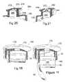
- FIG. 18is a schematic view, partially in section of a modified three piece closure according to the present invention.
- FIG. 19is a schematic view, partially in section of a further modified three piece closure according to the present invention.
- FIG. 20is a schematic view, partially in section of another modified three piece closure according to the present invention.
- FIG. 21is a schematic view of the closure of FIG. 20 in a dispensing position.
- a single use unit dosage dispensing closure 10is shown in the figures.
- the closure 10is adapted to be attached to a container 5 (shown in FIG. 6 in phantom) with a threaded neck finish 8 (e.g. a bottle).
- a container 5shown in FIG. 6 in phantom
- a threaded neck finish 8e.g. a bottle
- the closureincludes a shell 12 , shown alone in FIGS. 1-7 , which is adapted to be attached to the container.
- the shellhas an outer skirt 14 with a closure attaching mechanism in the form of threads 16 on the outer skirt 14 for attaching the shell 12 to the container.
- the lower portion 18 of the skirt 14may be formed as a tamper evident band, as is known in the art.
- the inner surface of the skirtmay include a sealing ring 20 for sealing against the neck finish of the container.
- the shell 12has a tubular inner guide 22 with an open lower end in communication with the interior of the container.
- the inner guide 22includes at least one sealing ring 24 , a lower stop 26 at a lower end thereof and an upper stop 28 at an upper end thereof.
- the inner guide 22further includes a finger access 30 adjacent an upper end thereof and a second stop 31 above the seal ring 24 .
- the shell 12may further include an alignment nub on the exterior of the guide 22 for alignment of the guide during manufacturing.
- a piercing element 32is formed integral with the inner guide 22 .
- the piercing element 32is formed a plurality of angled radial blades 34 at a lower end of the inner guide 22 , wherein the radial blades 34 converge to form a piercing tip extending toward the upper end of the inner guide 22 .
- the triangular center piercing tipgives a center point for gating of the shell 12 .
- Adjacent the blades 34are folding elements 36 that are adapted to engage and fold back a sealing element to facilitate discharge of the unit dosage as will be described.
- An important aspect of the present inventionis that all of the major seals, undercuts and other “jump” features (i.e. elements that effectively deform slightly in the de-molding process) are formed in or integral with the shell 12 .
- the shellis made of a polymer that accommodates such features, such as polyolefin. Materials that accommodate these jump features do not have significant moisture or gas barrier properties (i.e. high moisture and gas permeability).
- An axial movable cap 40is attached to the shell 12 and moveable along the inner guide 22 .
- the cap 40defines an inner chamber 42 therein adapted to hold a unit dosage of material to be dispensed into the container.
- the cap 40is of a simple configuration having a top 44 and a cylindrical side member 46 forming the chamber 42 .
- the simple construction (no jump features) of the cap 40allows a relatively rigid material to be used to form the cap 40 , whereby the cap 40 and the shell 12 are made from different polymer materials.
- the axial movable cap 40is formed from a material with a higher oxygen and water barrier property than the material forming the shell 12 .
- the cap 40may, preferably, be formed a rigid material such as polyethylene terephthalate (PET), nylon, polypropylene (PP) with low shrink filler, and polyethylene (PE) with low shrink filler.
- Low shrink fillersinclude talc and mica.
- a sealing layer, or even film, 50is coupled to the cap 40 at least prior to dispensing with the cap 40 , wherein the chamber 42 is sealed with the sealing layer 50 extending across a lower open end of the cap 40 at the open end of the cylindrical side member 46 .
- Axial movement of the cap 40 along the inner guide 22will cause the piercing element formed by blades 34 to pierce the sealing layer 50 and dispense the contents of the chamber 42 into the container.
- the folding elements 36engage the distinct pieces of the sealing layer and move them out of the way to further assist in the dispensing.
- the layer 50may be a metallic foil or a plastic film.
- the sealing ring 24 of the guide 22engages and seals against the cylindrical side member 46 .
- the upper stop 28 and the second stop 31engage against the top 44 to limit the respective axial motion of the cap 40 .
- the lower stop 26engages against the lower end of the cylindrical side member 46 .
- the closureadditionally includes a dust cover 60 shown in FIGS. 11-14 .
- the dust coverhas a top 62 with an extending cylindrical skirt 64 .
- a coupling bead 66will engage the shell 20 .
- the cover 60is removed prior to actuation of the dispensing closure and can further include tamper evident band for security.
- the shell 20would include associated engaging beads for such tamper evident bands, as generally known in the art.
- the addition of the dust cover 60may further assist in the stacking of vertical containers. Further, the dust cover 60 prevents premature actuation of the cap 40 , since the cap 40 cannot be pressed downward until the cover 60 is removed.
- FIG. 18is a schematic view, partially in section of a modified three piece closure 100 according to the present invention.
- the closure 100includes a shell 120 and cap 140 similar in function and operation as the shell 20 and cap 40 described above.
- the details of the shell 120such as the piercing elements, are not shown and can be formed the same as shell 20 .
- the difference in this embodimentis that the actuation of the axial movement of the cap 140 is though a rotational actuator 170 attached to the cap 140 .
- a threaded shaft 172extends from the actuator top 174 , through the shell 120 , and engages the cap 140 .
- This designshows seals 142 on the cap 140 and requires a more complex cap construction for the attachment of the shaft 172 to the cap 142 and for the formation of an anti-rotation mechanism (not shown) between the cap 140 and the shell 120 ⁇ e.g. a sliding key in an axial slot).
- the more complex cap constructionmay minimize the choices of material for forming the cap 140 , therefore the earlier embodiment is preferred.
- FIG. 19is a schematic view, partially in section of a further modified three piece closure 100 according to the present invention.
- This embodimentis essentially the same as described in FIG. 18 , except that the sealing member 50 is attached to a lower end of the shell 120 (and piercing elements thereof are omitted).
- This embodimentuses the lower end of the cap 140 as a piercing element and requires a good seal between the cap 140 and the shell 120 .
- the complex cap 140may be less advantageous than the cap 40 of the first design.
- FIGS. 20-21are schematic views, partially in section of another modified three piece closure 200 according to the present invention.
- This embodimentis essentially the same as described in FIG. 18 , except that the rotational actuator is in the form of a dispensing tip 270 having a central opening 272 therein.
- the threaded shaftis replaced with an internally threaded skirt 274 .
- the cap 240further includes a sealing plug 242 closing the central opening 272 when the cap 240 is in the uppermost position shown in FIG. 20 , and at least one opening 244 there-through to form a flow path when in the fully opened position and the foil or sealing layer has been removed or ruptured.
- the structure removing the sealing layeris not shown in detail but may be formed essentially as shown above.
- the cap 240is essentially an axial movable stem similar to stems of push pull closures (except in standard push pull closures the tip is slid away and toward the stem as opposed to vice-versa as in this closure). As shown in FIG. 21 the closure 200 is a dispensing closure once the cap 240 is moved away from the tip 270 and the sealing layer 50 is removed thereby opening the flow path from interior of the container to the exterior (as well as dispensing the contents of the cap into the container).
Landscapes
- Engineering & Computer Science (AREA)
- Mechanical Engineering (AREA)
- Closures For Containers (AREA)
Abstract
Description
Claims (20)
Priority Applications (1)
| Application Number | Priority Date | Filing Date | Title |
|---|---|---|---|
| US11/024,365US7506782B2 (en) | 2004-12-24 | 2004-12-24 | Single use unit dosage dispensing closure |
Applications Claiming Priority (1)
| Application Number | Priority Date | Filing Date | Title |
|---|---|---|---|
| US11/024,365US7506782B2 (en) | 2004-12-24 | 2004-12-24 | Single use unit dosage dispensing closure |
Publications (2)
| Publication Number | Publication Date |
|---|---|
| US20050236424A1 US20050236424A1 (en) | 2005-10-27 |
| US7506782B2true US7506782B2 (en) | 2009-03-24 |
Family
ID=35135424
Family Applications (1)
| Application Number | Title | Priority Date | Filing Date |
|---|---|---|---|
| US11/024,365Expired - Fee RelatedUS7506782B2 (en) | 2004-12-24 | 2004-12-24 | Single use unit dosage dispensing closure |
Country Status (1)
| Country | Link |
|---|---|
| US (1) | US7506782B2 (en) |
Cited By (14)
| Publication number | Priority date | Publication date | Assignee | Title |
|---|---|---|---|---|
| US20070280042A1 (en)* | 2004-09-29 | 2007-12-06 | Yoshino Kogyosyo Co., Ltd. | Container for mixing two liquids and the like |
| US20080067172A1 (en)* | 2005-03-23 | 2008-03-20 | Rene Wilhelm | Container Closure for a Container Comprising a So-Called "Push-Pull" Closure |
| US20100089860A1 (en)* | 2008-10-14 | 2010-04-15 | Mead Johnson & Company | Nutritive substance delivery container |
| US8613372B2 (en) | 2011-02-01 | 2013-12-24 | Granite State Product Development LLC | Dispensing cap for a container |
| US20150251837A1 (en)* | 2012-10-23 | 2015-09-10 | Alpla Werke Alwin Lehner Gmbh & Co. Kg | Container and method for adding a mixture component |
| US9352896B2 (en) | 2013-03-14 | 2016-05-31 | Berry Plastics Corporation | Dispenser apparatus |
| US9604765B2 (en) | 2013-03-14 | 2017-03-28 | Ahhmigo, Llc | Locking cap device and methods |
| US20170259982A1 (en)* | 2016-03-09 | 2017-09-14 | Phoenix Closures, Inc. | Dispensable containment vessel and dispensing system |
| US9919860B2 (en) | 2012-05-15 | 2018-03-20 | Yaacov Dabah | Cap device and methods |
| US10065775B2 (en) | 2011-02-01 | 2018-09-04 | Granite State Product Development LLC | Dispensing cap for a container |
| US20220024673A1 (en)* | 2020-07-22 | 2022-01-27 | Smart Cap Licensing Pty Ltd | Dispensing devices, systems, and methods |
| USD960667S1 (en) | 2020-06-16 | 2022-08-16 | Bacardi & Company Limited | Strainer for cocktail shaker |
| USD960623S1 (en) | 2020-06-16 | 2022-08-16 | Bacardi & Company Limited | Cocktail shaker |
| USD973484S1 (en) | 2020-06-16 | 2022-12-27 | Bacardi & Company Limited | Beverage-containing pod for cocktail shaker |
Families Citing this family (12)
| Publication number | Priority date | Publication date | Assignee | Title |
|---|---|---|---|---|
| US9452870B1 (en) | 1987-01-20 | 2016-09-27 | Michael Anderson | Two-piece double-sealed dispensing capsule with button blast and drink through feature |
| AU2005304789B2 (en)* | 2004-11-04 | 2012-02-23 | Viz Enterprises, Llc | Multi-chamber container and cap therefor |
| US20100236952A1 (en)* | 2004-12-24 | 2010-09-23 | Berry Plastics Corporation | Solute-dispensing closure |
| US20060006077A1 (en)* | 2004-12-24 | 2006-01-12 | Erie County Plastics Corporation | Dispensing closure with integral piercing unit |
| US20080149585A1 (en)* | 2006-12-20 | 2008-06-26 | Valentine Craig R | Flavor cap |
| FR2930140B1 (en)* | 2008-04-17 | 2011-04-22 | Philippe Perovitch | DEVICE FOR STORING, EXTENDED PREPARATION AND ADMINISTRATION OF A LOW ASSAY OF ACTIVE INGREDIENT |
| US8701906B1 (en) | 2008-12-31 | 2014-04-22 | Blast Max Llc | Ingredient dispensing cap for mixing beverages with push-pull drinking spout |
| US9567142B1 (en) | 2011-05-27 | 2017-02-14 | Michael Anderson | One-piece dispensing capsule with integral plunger |
| US9067716B2 (en) | 2011-09-30 | 2015-06-30 | Federico Intriago | Cap assembly for dispensing a dispensable component and method of making and using the same |
| US9051099B2 (en)* | 2012-12-13 | 2015-06-09 | Jose Rodrigo Oliva SALINAS | One piece dispensing lid |
| WO2018053196A1 (en)* | 2016-09-14 | 2018-03-22 | Horn Company | Ingredient dispensing cap for beverage container |
| WO2021021764A1 (en)* | 2019-07-27 | 2021-02-04 | Confirm Biosciences, Inc. | Specimen sample collection device with buffer-containing cap |
Citations (58)
| Publication number | Priority date | Publication date | Assignee | Title |
|---|---|---|---|---|
| US2631521A (en) | 1953-03-17 | Beverage mixing container | ||
| US2859898A (en) | 1956-10-03 | 1958-11-11 | Res Lab Inc | Container and a cap therefor, by means of which a user can prepare a fresh solution or suspension and can readily dispense the same |
| US3156369A (en)* | 1962-09-19 | 1964-11-10 | Ethicon Inc | Bicameral container |
| US3404811A (en)* | 1966-12-02 | 1968-10-08 | Cernei Jose | Container for maintaining in separate condition liquids which are to be mixed together and which may be manipulated to commingle such liquids |
| US3521745A (en) | 1968-07-31 | 1970-07-28 | Gilbert Schwartzman | Mixing package |
| US3603469A (en) | 1968-04-11 | 1971-09-07 | Ambrogio Magni | Guarantee cap |
| US3655035A (en) | 1967-11-23 | 1972-04-11 | Zahn Porzellan Kg E Muehlbauer | Multiplex capsule for dental filling materials |
| US3715189A (en) | 1970-06-15 | 1973-02-06 | Secretary Of The Treasury | Qualitative analysis device |
| US3841467A (en) | 1972-06-20 | 1974-10-15 | Univ Missouri | Product and process for making improved strength dental amalgam |
| US3968872A (en) | 1973-08-03 | 1976-07-13 | Sigma-Tau | Device, provided with a puncher and a dripper, for the hermetic sealing of containers |
| US4011945A (en) | 1974-09-13 | 1977-03-15 | National Research Development Corporation | First aid equipment |
| US4195731A (en) | 1978-04-27 | 1980-04-01 | Claudio Cavazza | Device for containing a substance to be mixed with another substance in a vial |
| US4203517A (en)* | 1977-12-02 | 1980-05-20 | Wella Aktiengesellschaft | Container |
| US4221291A (en) | 1978-06-20 | 1980-09-09 | General Foods Corporation | Container having separate storage facilities for two materials |
| US4315570A (en) | 1979-01-04 | 1982-02-16 | Jules Silver | Two-compartment container with means for dispersing contents of one compartment into the other compartment |
| US4615437A (en) | 1984-07-20 | 1986-10-07 | Robert Finke Kommanditgesellschaft | Bottle closure with separable capsule |
| US4682689A (en)* | 1986-06-27 | 1987-07-28 | Clairol Incorporated | Dual compartment container |
| US4693366A (en)* | 1986-01-10 | 1987-09-15 | The French Joint Stock Company "L'oreal" | Packaging means in two parts |
| US4757916A (en)* | 1986-09-12 | 1988-07-19 | L'oreal | Unit allowing two products to be stored separately and to be simultaneously dispensed after they have been brought into contact |
| US4776972A (en) | 1984-04-04 | 1988-10-11 | Purex Corporation | Adjustable strength laundry bleaching using a two compartment package |
| US4805799A (en)* | 1988-03-04 | 1989-02-21 | Robbins Edward S Iii | Container with unitary bladder |
| US4858760A (en) | 1987-07-02 | 1989-08-22 | Paolo Di Sturco | Compound cap for use with a bottle |
| US4858759A (en) | 1985-12-21 | 1989-08-22 | Hilti Aktiengesellschaft | Container arrangement for cartridge dispensing two-component mass |
| US4898293A (en) | 1987-05-25 | 1990-02-06 | Societe De Conseils Et D'etudes Des Emballages S.C.E.E. | Closing device for containers |
| US4903865A (en) | 1988-09-19 | 1990-02-27 | Janowitz C Michael | Push button cap containing an additive for containers |
| US4982875A (en)* | 1985-08-02 | 1991-01-08 | Zambon S.P.A. | Cap, reservoir and dropper assembly for bottles |
| US5029718A (en) | 1988-09-01 | 1991-07-09 | Capsulit S.P.A. | Closure for bottles and the like comprising a reservoir with a breakable bottom |
| US5038951A (en) | 1988-04-18 | 1991-08-13 | Napoleone Rizzardi | Closure for monodose bottles and the like, comprising a reservoir provided with a breakable bottom |
| US5246142A (en) | 1991-09-26 | 1993-09-21 | Dipalma Elio | Device for storing two products separately and subsequently mixing them |
| US5380315A (en)* | 1992-02-04 | 1995-01-10 | Material Engineering Technology Laboratory Incorporated | Mixing apparatus |
| US5419445A (en) | 1994-06-24 | 1995-05-30 | Kaesemeyer; David M. | Container for storing, mixing and dispensing |
| US5474209A (en)* | 1992-07-02 | 1995-12-12 | Laboratorios Cusi, S.A. | Pharmaceutical product container with two separate substances and a mixing device and dosed dispensation |
| US5509530A (en) | 1995-07-20 | 1996-04-23 | Wykle Research, Inc. | Compartmentalized dental amalgam mixing capsule |
| US5697495A (en) | 1993-11-02 | 1997-12-16 | Johnson & Johnson Vision Products, Inc. | Packaging arrangement for contact lenses |
| US5772017A (en) | 1996-10-25 | 1998-06-30 | Kang; Heung Sun | Beverage mixing dispenser device |
| US5813570A (en)* | 1994-04-08 | 1998-09-29 | Ing. Erich Pfeiffer Gmbh | Apparatus for controllably discharging flowable media |
| US5941380A (en) | 1998-01-10 | 1999-08-24 | Rothman; David | Device for dispensing flowable material |
| US5950819A (en) | 1998-05-08 | 1999-09-14 | Sellars; Andy | Storage, admixing, and dispensing system |
| US6098795A (en) | 1997-10-14 | 2000-08-08 | Mollstam; Bo | Device for adding a component to a package |
| US6138821A (en) | 1999-11-26 | 2000-10-31 | Hsu; Lily | Container device for separately enclosing two different substances |
| US6165523A (en) | 1999-04-26 | 2000-12-26 | Story; Douglas | Injector bottle cap assembly |
| US6170654B1 (en) | 1996-06-27 | 2001-01-09 | Bradley Francis Gartner | Closure cap having blister pack rupturable upon opening of cap |
| US6224922B1 (en) | 1999-12-16 | 2001-05-01 | Mark J. Fonte | Drink colorizer |
| US6305576B1 (en) | 2000-01-19 | 2001-10-23 | Nalge Nunc International Corporation | Cartridge for aseptically holding and dispensing a fluid material, and a container and method for aseptically holding and mixing the fluid material |
| US6372270B1 (en) | 1999-05-26 | 2002-04-16 | Sean P. Denny | Drink mix apparatus for making personal quantities of beverage |
| US20030072850A1 (en) | 2001-10-16 | 2003-04-17 | Burniski Edward William | Bottle cap drink mix reservoir |
| US20040026270A1 (en) | 2002-08-07 | 2004-02-12 | Shou-Long Liang | Solution bottle capable of isolating reactant from solution |
| US20040161504A1 (en) | 2003-02-14 | 2004-08-19 | The Procter & Gamble Co. | Mineral fortification systems |
| US6820740B1 (en) | 2003-06-18 | 2004-11-23 | Donald Spector | Universal cap for dispensing materials by retrofit upon existing bottled beverage containers |
| US6921087B2 (en)* | 2002-08-20 | 2005-07-26 | Nippon Tansan Gas Co., Ltd. | Sealing mechanism for vessel and cap to be used in the mechanism |
| US6935493B2 (en)* | 2003-04-12 | 2005-08-30 | Young Kook Cho | Cap device for mixing different kinds of materials separately contained therein and in bottle |
| US20050218015A1 (en) | 2003-06-18 | 2005-10-06 | Donald Spector | Universal bottle cap |
| US6959839B2 (en)* | 2003-02-10 | 2005-11-01 | Donna Roth | Flavoring component holding dispenser for use with consumable beverages |
| US6962254B2 (en) | 2003-06-18 | 2005-11-08 | Donald Spector | Universal bottle cap |
| USD514949S1 (en) | 2003-12-02 | 2006-02-14 | Procter & Gamble | Container |
| USD515934S1 (en) | 2003-12-02 | 2006-02-28 | Procter & Gamble | Container |
| US7169419B2 (en) | 2001-06-04 | 2007-01-30 | The Procter And Gamble Company | Packaging system to provide fresh packed coffee |
| US7249690B2 (en)* | 2004-12-24 | 2007-07-31 | Erie County Plastics Corporation | Independent off-bottle dispensing closure |
Family Cites Families (1)
| Publication number | Priority date | Publication date | Assignee | Title |
|---|---|---|---|---|
| CA2329969A1 (en)* | 1999-02-26 | 2000-08-31 | Bodo Hildebrandt | Device for mixing, foaming and dispensing liquids from separate compressed-gas containers |
- 2004
- 2004-12-24USUS11/024,365patent/US7506782B2/ennot_activeExpired - Fee Related
Patent Citations (59)
| Publication number | Priority date | Publication date | Assignee | Title |
|---|---|---|---|---|
| US2631521A (en) | 1953-03-17 | Beverage mixing container | ||
| US2859898A (en) | 1956-10-03 | 1958-11-11 | Res Lab Inc | Container and a cap therefor, by means of which a user can prepare a fresh solution or suspension and can readily dispense the same |
| US3156369A (en)* | 1962-09-19 | 1964-11-10 | Ethicon Inc | Bicameral container |
| US3404811A (en)* | 1966-12-02 | 1968-10-08 | Cernei Jose | Container for maintaining in separate condition liquids which are to be mixed together and which may be manipulated to commingle such liquids |
| US3655035A (en) | 1967-11-23 | 1972-04-11 | Zahn Porzellan Kg E Muehlbauer | Multiplex capsule for dental filling materials |
| US3603469A (en) | 1968-04-11 | 1971-09-07 | Ambrogio Magni | Guarantee cap |
| US3521745A (en) | 1968-07-31 | 1970-07-28 | Gilbert Schwartzman | Mixing package |
| US3715189A (en) | 1970-06-15 | 1973-02-06 | Secretary Of The Treasury | Qualitative analysis device |
| US3841467A (en) | 1972-06-20 | 1974-10-15 | Univ Missouri | Product and process for making improved strength dental amalgam |
| US3968872A (en) | 1973-08-03 | 1976-07-13 | Sigma-Tau | Device, provided with a puncher and a dripper, for the hermetic sealing of containers |
| US4011945A (en) | 1974-09-13 | 1977-03-15 | National Research Development Corporation | First aid equipment |
| US4203517A (en)* | 1977-12-02 | 1980-05-20 | Wella Aktiengesellschaft | Container |
| US4195731A (en) | 1978-04-27 | 1980-04-01 | Claudio Cavazza | Device for containing a substance to be mixed with another substance in a vial |
| US4221291A (en) | 1978-06-20 | 1980-09-09 | General Foods Corporation | Container having separate storage facilities for two materials |
| US4315570A (en) | 1979-01-04 | 1982-02-16 | Jules Silver | Two-compartment container with means for dispersing contents of one compartment into the other compartment |
| US4776972A (en) | 1984-04-04 | 1988-10-11 | Purex Corporation | Adjustable strength laundry bleaching using a two compartment package |
| US4615437A (en) | 1984-07-20 | 1986-10-07 | Robert Finke Kommanditgesellschaft | Bottle closure with separable capsule |
| US4982875A (en)* | 1985-08-02 | 1991-01-08 | Zambon S.P.A. | Cap, reservoir and dropper assembly for bottles |
| US4858759A (en) | 1985-12-21 | 1989-08-22 | Hilti Aktiengesellschaft | Container arrangement for cartridge dispensing two-component mass |
| US4693366A (en)* | 1986-01-10 | 1987-09-15 | The French Joint Stock Company "L'oreal" | Packaging means in two parts |
| US4682689A (en)* | 1986-06-27 | 1987-07-28 | Clairol Incorporated | Dual compartment container |
| US4757916A (en)* | 1986-09-12 | 1988-07-19 | L'oreal | Unit allowing two products to be stored separately and to be simultaneously dispensed after they have been brought into contact |
| US4898293A (en) | 1987-05-25 | 1990-02-06 | Societe De Conseils Et D'etudes Des Emballages S.C.E.E. | Closing device for containers |
| US4858760A (en) | 1987-07-02 | 1989-08-22 | Paolo Di Sturco | Compound cap for use with a bottle |
| US4805799A (en)* | 1988-03-04 | 1989-02-21 | Robbins Edward S Iii | Container with unitary bladder |
| US5038951A (en) | 1988-04-18 | 1991-08-13 | Napoleone Rizzardi | Closure for monodose bottles and the like, comprising a reservoir provided with a breakable bottom |
| US5029718A (en) | 1988-09-01 | 1991-07-09 | Capsulit S.P.A. | Closure for bottles and the like comprising a reservoir with a breakable bottom |
| US4903865A (en) | 1988-09-19 | 1990-02-27 | Janowitz C Michael | Push button cap containing an additive for containers |
| US5246142A (en) | 1991-09-26 | 1993-09-21 | Dipalma Elio | Device for storing two products separately and subsequently mixing them |
| US5380315A (en)* | 1992-02-04 | 1995-01-10 | Material Engineering Technology Laboratory Incorporated | Mixing apparatus |
| US5474209A (en)* | 1992-07-02 | 1995-12-12 | Laboratorios Cusi, S.A. | Pharmaceutical product container with two separate substances and a mixing device and dosed dispensation |
| US5697495A (en) | 1993-11-02 | 1997-12-16 | Johnson & Johnson Vision Products, Inc. | Packaging arrangement for contact lenses |
| US5813570A (en)* | 1994-04-08 | 1998-09-29 | Ing. Erich Pfeiffer Gmbh | Apparatus for controllably discharging flowable media |
| US5419445A (en) | 1994-06-24 | 1995-05-30 | Kaesemeyer; David M. | Container for storing, mixing and dispensing |
| US5509530A (en) | 1995-07-20 | 1996-04-23 | Wykle Research, Inc. | Compartmentalized dental amalgam mixing capsule |
| US6170654B1 (en) | 1996-06-27 | 2001-01-09 | Bradley Francis Gartner | Closure cap having blister pack rupturable upon opening of cap |
| US5772017A (en) | 1996-10-25 | 1998-06-30 | Kang; Heung Sun | Beverage mixing dispenser device |
| US6098795A (en) | 1997-10-14 | 2000-08-08 | Mollstam; Bo | Device for adding a component to a package |
| US5941380A (en) | 1998-01-10 | 1999-08-24 | Rothman; David | Device for dispensing flowable material |
| US5950819A (en) | 1998-05-08 | 1999-09-14 | Sellars; Andy | Storage, admixing, and dispensing system |
| US6092648A (en) | 1998-05-08 | 2000-07-25 | Sellars; Andy | Storage, admixing, and dispensing system |
| US6165523A (en) | 1999-04-26 | 2000-12-26 | Story; Douglas | Injector bottle cap assembly |
| US6372270B1 (en) | 1999-05-26 | 2002-04-16 | Sean P. Denny | Drink mix apparatus for making personal quantities of beverage |
| US6138821A (en) | 1999-11-26 | 2000-10-31 | Hsu; Lily | Container device for separately enclosing two different substances |
| US6224922B1 (en) | 1999-12-16 | 2001-05-01 | Mark J. Fonte | Drink colorizer |
| US6305576B1 (en) | 2000-01-19 | 2001-10-23 | Nalge Nunc International Corporation | Cartridge for aseptically holding and dispensing a fluid material, and a container and method for aseptically holding and mixing the fluid material |
| US7169419B2 (en) | 2001-06-04 | 2007-01-30 | The Procter And Gamble Company | Packaging system to provide fresh packed coffee |
| US20030072850A1 (en) | 2001-10-16 | 2003-04-17 | Burniski Edward William | Bottle cap drink mix reservoir |
| US20040026270A1 (en) | 2002-08-07 | 2004-02-12 | Shou-Long Liang | Solution bottle capable of isolating reactant from solution |
| US6921087B2 (en)* | 2002-08-20 | 2005-07-26 | Nippon Tansan Gas Co., Ltd. | Sealing mechanism for vessel and cap to be used in the mechanism |
| US6959839B2 (en)* | 2003-02-10 | 2005-11-01 | Donna Roth | Flavoring component holding dispenser for use with consumable beverages |
| US20040161504A1 (en) | 2003-02-14 | 2004-08-19 | The Procter & Gamble Co. | Mineral fortification systems |
| US6935493B2 (en)* | 2003-04-12 | 2005-08-30 | Young Kook Cho | Cap device for mixing different kinds of materials separately contained therein and in bottle |
| US20050218015A1 (en) | 2003-06-18 | 2005-10-06 | Donald Spector | Universal bottle cap |
| US6962254B2 (en) | 2003-06-18 | 2005-11-08 | Donald Spector | Universal bottle cap |
| US6820740B1 (en) | 2003-06-18 | 2004-11-23 | Donald Spector | Universal cap for dispensing materials by retrofit upon existing bottled beverage containers |
| USD514949S1 (en) | 2003-12-02 | 2006-02-14 | Procter & Gamble | Container |
| USD515934S1 (en) | 2003-12-02 | 2006-02-28 | Procter & Gamble | Container |
| US7249690B2 (en)* | 2004-12-24 | 2007-07-31 | Erie County Plastics Corporation | Independent off-bottle dispensing closure |
Cited By (21)
| Publication number | Priority date | Publication date | Assignee | Title |
|---|---|---|---|---|
| US9718598B2 (en) | 2004-09-29 | 2017-08-01 | Yoshino Kogyosho Co., Ltd. | Container for mixing two fluids |
| US20070280042A1 (en)* | 2004-09-29 | 2007-12-06 | Yoshino Kogyosyo Co., Ltd. | Container for mixing two liquids and the like |
| US8714808B2 (en)* | 2004-09-29 | 2014-05-06 | Yoshino Kogyosho Co., Ltd. | Container for mixing two fluids |
| US20080067172A1 (en)* | 2005-03-23 | 2008-03-20 | Rene Wilhelm | Container Closure for a Container Comprising a So-Called "Push-Pull" Closure |
| US20100089860A1 (en)* | 2008-10-14 | 2010-04-15 | Mead Johnson & Company | Nutritive substance delivery container |
| US8801688B2 (en)* | 2008-10-14 | 2014-08-12 | Mead Johnson Nutrition Company | Nutritive substance delivery container |
| US8613372B2 (en) | 2011-02-01 | 2013-12-24 | Granite State Product Development LLC | Dispensing cap for a container |
| US10065775B2 (en) | 2011-02-01 | 2018-09-04 | Granite State Product Development LLC | Dispensing cap for a container |
| US9919860B2 (en) | 2012-05-15 | 2018-03-20 | Yaacov Dabah | Cap device and methods |
| US20150251837A1 (en)* | 2012-10-23 | 2015-09-10 | Alpla Werke Alwin Lehner Gmbh & Co. Kg | Container and method for adding a mixture component |
| US10562691B2 (en)* | 2012-10-23 | 2020-02-18 | Alpla Werke Alwin Lehner Gmbh & Co. Kg | Container and method for adding a mixture component |
| US9352896B2 (en) | 2013-03-14 | 2016-05-31 | Berry Plastics Corporation | Dispenser apparatus |
| US9604765B2 (en) | 2013-03-14 | 2017-03-28 | Ahhmigo, Llc | Locking cap device and methods |
| US20170259982A1 (en)* | 2016-03-09 | 2017-09-14 | Phoenix Closures, Inc. | Dispensable containment vessel and dispensing system |
| US10494164B2 (en)* | 2016-03-09 | 2019-12-03 | Fifth Third Bank, an Ohio Banking | Dispensable containment vessel and dispensing system |
| AU2017201023B2 (en)* | 2016-03-09 | 2021-08-05 | Phoenix Closures, Inc. | Dispensable containment vessel and dispensing system |
| USD960667S1 (en) | 2020-06-16 | 2022-08-16 | Bacardi & Company Limited | Strainer for cocktail shaker |
| USD960623S1 (en) | 2020-06-16 | 2022-08-16 | Bacardi & Company Limited | Cocktail shaker |
| USD973484S1 (en) | 2020-06-16 | 2022-12-27 | Bacardi & Company Limited | Beverage-containing pod for cocktail shaker |
| US20220024673A1 (en)* | 2020-07-22 | 2022-01-27 | Smart Cap Licensing Pty Ltd | Dispensing devices, systems, and methods |
| US11780665B2 (en)* | 2020-07-22 | 2023-10-10 | Smart Cap Licensing Pty Ltd | Dispensing devices, systems, and methods |
Also Published As
| Publication number | Publication date |
|---|---|
| US20050236424A1 (en) | 2005-10-27 |
Similar Documents
| Publication | Publication Date | Title |
|---|---|---|
| US7506782B2 (en) | Single use unit dosage dispensing closure | |
| US7249690B2 (en) | Independent off-bottle dispensing closure | |
| US20060006077A1 (en) | Dispensing closure with integral piercing unit | |
| AU2007246847B2 (en) | Container closure having means for introducing an additive into the contents of the container | |
| US9045269B2 (en) | Container closure having means for introducing an additive into the contents of the container | |
| US20100012532A1 (en) | Container closure having a spout and means for introducing an additive into the contents of the container | |
| US20090321286A1 (en) | Container closure having a lifting cap for introducing an additive into the contents of the container | |
| US9523596B2 (en) | Auto-refill single dose dispenser | |
| EP3157834B1 (en) | Closure with storage chamber | |
| US20200062464A1 (en) | Coupled structure between pouring spout of refill container and pouring unit of packaging container | |
| US10472142B2 (en) | Closure device for a container | |
| US8020696B2 (en) | Device and method for storing and mixing at least two materials | |
| JP2018062351A (en) | Spout for refilling container and refilling container with spout | |
| LU101902B1 (en) | Recipient to dispense or receive a product for in situ mixing | |
| JP2010509143A (en) | Dispensing head with hinge cap | |
| JP7703389B2 (en) | Hinge Cap | |
| JP2016120938A (en) | Composite liquid discharge cap capable of discharging by small amount | |
| CN219506641U (en) | Bottle cap with storage cavity and container | |
| KR200462267Y1 (en) | Cap structure of a container for liquid | |
| JP6808462B2 (en) | Weighing discharge container | |
| JP2013139267A (en) | Tap member for refill container | |
| HK1137708B (en) | Dispensing head with hinged cap | |
| HK1196805B (en) | Container closure having means for introducing an additive into the contents of the container | |
| HK1196805A (en) | Container closure having means for introducing an additive into the contents of the container |
Legal Events
| Date | Code | Title | Description |
|---|---|---|---|
| AS | Assignment | Owner name:ERIE COUNTY PLASTICS CORPORATION, PENNSYLVANIA Free format text:ASSIGNMENT OF ASSIGNORS INTEREST;ASSIGNORS:WALTERS, RONALD J.;SMITH, ROBERT J.;REEL/FRAME:015976/0595 Effective date:20050323 | |
| AS | Assignment | Owner name:BANK ONE, N.A., OHIO Free format text:SECURITY AGREEMENT;ASSIGNOR:ERIE COUNTY PLASTICS CORPORATION;REEL/FRAME:020753/0786 Effective date:20040928 Owner name:BANK ONE, N.A.,OHIO Free format text:SECURITY AGREEMENT;ASSIGNOR:ERIE COUNTY PLASTICS CORPORATION;REEL/FRAME:020753/0786 Effective date:20040928 | |
| AS | Assignment | Owner name:JPMORGAN CHASE BANK, N.A. (SUCCESSOR IN INTEREST T Free format text:CHANGE OF NAME;ASSIGNOR:BANK ONE, N.A.;REEL/FRAME:020762/0412 Effective date:20040701 | |
| AS | Assignment | Owner name:BERRY PLASTICS CORPORATION, INDIANA Free format text:ASSIGNMENT OF ASSIGNORS INTEREST;ASSIGNOR:ERIE COUNTY PLASTICS CORPORATION;REEL/FRAME:022917/0232 Effective date:20081120 Owner name:BERRY PLASTICS CORPORATION,INDIANA Free format text:ASSIGNMENT OF ASSIGNORS INTEREST;ASSIGNOR:ERIE COUNTY PLASTICS CORPORATION;REEL/FRAME:022917/0232 Effective date:20081120 | |
| REMI | Maintenance fee reminder mailed | ||
| LAPS | Lapse for failure to pay maintenance fees | ||
| STCH | Information on status: patent discontinuation | Free format text:PATENT EXPIRED DUE TO NONPAYMENT OF MAINTENANCE FEES UNDER 37 CFR 1.362 | |
| FP | Lapsed due to failure to pay maintenance fee | Effective date:20130324 |