US7506706B2 - Retaining element for a jack element - Google Patents
Retaining element for a jack elementDownload PDFInfo
- Publication number
- US7506706B2 US7506706B2US11/774,645US77464507AUS7506706B2US 7506706 B2US7506706 B2US 7506706B2US 77464507 AUS77464507 AUS 77464507AUS 7506706 B2US7506706 B2US 7506706B2
- Authority
- US
- United States
- Prior art keywords
- bit
- motor
- bore
- retaining element
- jack
- Prior art date
- Legal status (The legal status is an assumption and is not a legal conclusion. Google has not performed a legal analysis and makes no representation as to the accuracy of the status listed.)
- Expired - Fee Related, expires
Links
- 238000005520cutting processMethods0.000claimsabstractdescription22
- 230000000717retained effectEffects0.000claimsabstractdescription5
- 229910003460diamondInorganic materials0.000claimsdescription25
- 239000010432diamondSubstances0.000claimsdescription25
- 239000000463materialSubstances0.000claimsdescription12
- XEEYBQQBJWHFJM-UHFFFAOYSA-NIronChemical compound[Fe]XEEYBQQBJWHFJM-UHFFFAOYSA-N0.000claimsdescription8
- PXHVJJICTQNCMI-UHFFFAOYSA-NNickelChemical compound[Ni]PXHVJJICTQNCMI-UHFFFAOYSA-N0.000claimsdescription8
- BASFCYQUMIYNBI-UHFFFAOYSA-NplatinumChemical compound[Pt]BASFCYQUMIYNBI-UHFFFAOYSA-N0.000claimsdescription8
- 229910052582BNInorganic materials0.000claimsdescription7
- PZNSFCLAULLKQX-UHFFFAOYSA-NBoron nitrideChemical compoundN#BPZNSFCLAULLKQX-UHFFFAOYSA-N0.000claimsdescription7
- 229910017052cobaltInorganic materials0.000claimsdescription7
- 239000010941cobaltSubstances0.000claimsdescription7
- GUTLYIVDDKVIGB-UHFFFAOYSA-Ncobalt atomChemical compound[Co]GUTLYIVDDKVIGB-UHFFFAOYSA-N0.000claimsdescription7
- UONOETXJSWQNOL-UHFFFAOYSA-Ntungsten carbideChemical compound[W+]#[C-]UONOETXJSWQNOL-UHFFFAOYSA-N0.000claimsdescription7
- 230000006698inductionEffects0.000claimsdescription6
- 230000001360synchronised effectEffects0.000claimsdescription6
- RTAQQCXQSZGOHL-UHFFFAOYSA-NTitaniumChemical compound[Ti]RTAQQCXQSZGOHL-UHFFFAOYSA-N0.000claimsdescription5
- 239000011248coating agentSubstances0.000claimsdescription5
- 238000000576coating methodMethods0.000claimsdescription5
- 238000004891communicationMethods0.000claimsdescription5
- 239000010936titaniumSubstances0.000claimsdescription5
- 229910052719titaniumInorganic materials0.000claimsdescription5
- ZOKXTWBITQBERF-UHFFFAOYSA-NMolybdenumChemical compound[Mo]ZOKXTWBITQBERF-UHFFFAOYSA-N0.000claimsdescription4
- PCHJSUWPFVWCPO-UHFFFAOYSA-NgoldChemical compound[Au]PCHJSUWPFVWCPO-UHFFFAOYSA-N0.000claimsdescription4
- 229910052737goldInorganic materials0.000claimsdescription4
- 239000010931goldSubstances0.000claimsdescription4
- 229910052742ironInorganic materials0.000claimsdescription4
- 229910052751metalInorganic materials0.000claimsdescription4
- 239000002184metalSubstances0.000claimsdescription4
- 229910052750molybdenumInorganic materials0.000claimsdescription4
- 239000011733molybdenumSubstances0.000claimsdescription4
- 229910052759nickelInorganic materials0.000claimsdescription4
- 229910052758niobiumInorganic materials0.000claimsdescription4
- 239000010955niobiumSubstances0.000claimsdescription4
- GUCVJGMIXFAOAE-UHFFFAOYSA-Nniobium atomChemical compound[Nb]GUCVJGMIXFAOAE-UHFFFAOYSA-N0.000claimsdescription4
- 229910052697platinumInorganic materials0.000claimsdescription4
- 239000003870refractory metalSubstances0.000claimsdescription4
- 229910052709silverInorganic materials0.000claimsdescription4
- 239000004332silverSubstances0.000claimsdescription4
- 230000005540biological transmissionEffects0.000claimsdescription3
- 238000005299abrasionMethods0.000claimsdescription2
- 238000005553drillingMethods0.000description26
- 230000015572biosynthetic processEffects0.000description20
- 238000005755formation reactionMethods0.000description20
- 238000010586diagramMethods0.000description10
- 239000012530fluidSubstances0.000description5
- 230000035515penetrationEffects0.000description3
- 229910000831SteelInorganic materials0.000description2
- 230000001133accelerationEffects0.000description2
- 230000007423decreaseEffects0.000description2
- 230000001066destructive effectEffects0.000description2
- 239000011159matrix materialSubstances0.000description2
- 238000000034methodMethods0.000description2
- 239000003921oilSubstances0.000description2
- 239000010959steelSubstances0.000description2
- VYZAMTAEIAYCRO-UHFFFAOYSA-NChromiumChemical compound[Cr]VYZAMTAEIAYCRO-UHFFFAOYSA-N0.000description1
- 229910000760Hardened steelInorganic materials0.000description1
- XUIMIQQOPSSXEZ-UHFFFAOYSA-NSiliconChemical group[Si]XUIMIQQOPSSXEZ-UHFFFAOYSA-N0.000description1
- 229910052782aluminiumInorganic materials0.000description1
- XAGFODPZIPBFFR-UHFFFAOYSA-NaluminiumChemical compound[Al]XAGFODPZIPBFFR-UHFFFAOYSA-N0.000description1
- 230000003466anti-cipated effectEffects0.000description1
- 230000000712assemblyEffects0.000description1
- 238000000429assemblyMethods0.000description1
- 239000011230binding agentSubstances0.000description1
- 229910052804chromiumInorganic materials0.000description1
- 239000011651chromiumSubstances0.000description1
- 230000003292diminished effectEffects0.000description1
- 230000000694effectsEffects0.000description1
- 238000005259measurementMethods0.000description1
- 238000005065miningMethods0.000description1
- 238000012986modificationMethods0.000description1
- 230000004048modificationEffects0.000description1
- 230000010355oscillationEffects0.000description1
- 239000011435rockSubstances0.000description1
- 229910052710siliconInorganic materials0.000description1
- 239000010703siliconSubstances0.000description1
- XLYOFNOQVPJJNP-UHFFFAOYSA-NwaterSubstancesOXLYOFNOQVPJJNP-UHFFFAOYSA-N0.000description1
- 230000003313weakening effectEffects0.000description1
Images


Classifications
- E—FIXED CONSTRUCTIONS
- E21—EARTH OR ROCK DRILLING; MINING
- E21B—EARTH OR ROCK DRILLING; OBTAINING OIL, GAS, WATER, SOLUBLE OR MELTABLE MATERIALS OR A SLURRY OF MINERALS FROM WELLS
- E21B7/00—Special methods or apparatus for drilling
- E21B7/04—Directional drilling
- E21B7/06—Deflecting the direction of boreholes
- E21B7/065—Deflecting the direction of boreholes using oriented fluid jets
- E—FIXED CONSTRUCTIONS
- E21—EARTH OR ROCK DRILLING; MINING
- E21B—EARTH OR ROCK DRILLING; OBTAINING OIL, GAS, WATER, SOLUBLE OR MELTABLE MATERIALS OR A SLURRY OF MINERALS FROM WELLS
- E21B10/00—Drill bits
- E21B10/26—Drill bits with leading portion, i.e. drill bits with a pilot cutter; Drill bits for enlarging the borehole, e.g. reamers
- E—FIXED CONSTRUCTIONS
- E21—EARTH OR ROCK DRILLING; MINING
- E21B—EARTH OR ROCK DRILLING; OBTAINING OIL, GAS, WATER, SOLUBLE OR MELTABLE MATERIALS OR A SLURRY OF MINERALS FROM WELLS
- E21B10/00—Drill bits
- E21B10/62—Drill bits characterised by parts, e.g. cutting elements, which are detachable or adjustable
- E—FIXED CONSTRUCTIONS
- E21—EARTH OR ROCK DRILLING; MINING
- E21B—EARTH OR ROCK DRILLING; OBTAINING OIL, GAS, WATER, SOLUBLE OR MELTABLE MATERIALS OR A SLURRY OF MINERALS FROM WELLS
- E21B7/00—Special methods or apparatus for drilling
- E21B7/04—Directional drilling
- E21B7/06—Deflecting the direction of boreholes
- E21B7/064—Deflecting the direction of boreholes specially adapted drill bits therefor
Definitions
- U.S. patent application Ser. No. 11/278,935filed on Apr. 6, 2006 now U.S. Pat. No. 7,426,968.
- U.S. patent application Ser. No. 11/278,935is a continuation-in-part of U.S. patent application Ser. No. 11/277,394 which filed on Mar. 24, 2006 now U.S. Pat. No. 7,398,837.
- U.S. patent application Ser. No. 11/277,394is a continuation-in-part of U.S. patent application Ser. No. 11/277,380 also filed on Mar. 24, 2006.
- U.S. patent application Ser. No. 11/277,380is a continuation-in-part of U.S. patent application Ser. No. 11/306,976 which was filed on Jan. 18, 2006.
- patent application Ser. No. 11/306,976is a continuation-in-part of 11/306,307 filed on Dec. 22, 2005.
- U.S. patent application Ser. No. 11/306,307is a continuation-in-part of U.S. patent application Ser. No. 11/306,022 filed on Dec. 14, 2005.
- U.S. patent application Ser. No. 11/306,022is a continuation-in-part of U.S. patent application Ser. No. 11/164,391 filed on Nov. 21, 2005. All of these applications are herein incorporated by reference in their entirety.
- Drill bitsare continuously exposed to harsh conditions during drilling operations in the earth's surface.
- Bit whirl in hard formationsfor example may result in damage to the drill bit and reduce penetration rates.
- Further loading too much weight on the drill bit when drilling through a hard formationmay exceed the bit's capabilities and also result in damage.
- Too often unexpected hard formationsare encountered suddenly and damage to the drill bit occurs before the weight on the drill bit may be adjusted.
- the cost of the bitis not considered so much as the associated down time required to maintain or replace a worn or expired bit.
- To replace a bitrequires removal of the drill string from the bore in order to service the bit which translates into significant economic losses until drilling can be resumed.
- U.S. Pat. No. 6,298,930 to Sinorwhich is herein incorporated by reference for all that it contains, discloses a rotary drag bit including exterior features to control the depth of cut by cutters mounted thereon, so as to control the volume of formation material cut per bit rotation as well as the torque experienced by the bit and an associated bottomhole assembly.
- the exterior featurespreferably precede, taken in the direction of bit rotation, cutters with which they are associated, and provide sufficient bearing area so as to support the bit against the bottom of the borehole under weight on bit without exceeding the compressive strength of the formation rock.
- the modelis reduced so to retain only pertinent modes, at least two values Rf and Rwob are calculated, Rf being a function of the principal oscillation frequency of weight on hook WOH divided by the average instantaneous rotating speed at the surface, Rwob being a function of the standard deviation of the signal of the weight on bit WOB estimated by the reduced longitudinal model from measurement of the signal of the weight on hook WOH, divided by the average weight on bit defined from the weight of the string and the average weight on hook. Any danger from the longitudinal behavior of the drill bit is determined from the values of Rf and Rwob.
- U.S. Pat. No. 5,806,611 to Van Den Steenwhich is herein incorporated by reference for all that it contains, discloses a device for controlling weight on bit of a drilling assembly for drilling a borehole in an earth formation.
- the deviceincludes a fluid passage for the drilling fluid flowing through the drilling assembly, and control means for controlling the flow resistance of drilling fluid in the passage in a manner that the flow resistance increases when the fluid pressure in the passage decreases and that the flow resistance decreases when the fluid pressure in the passage increases.
- U.S. Pat. No. 5,864,058 to Chenwhich is herein incorporated by reference for all that is contains, discloses a down hole sensor sub in the lower end of a drillstring, such sub having three orthogonally positioned accelerometers for measuring vibration of a drilling component.
- the lateral accelerationis measured along either the X or Y axis and then analyzed in the frequency domain as to peak frequency and magnitude at such peak frequency.
- Backward whirling of the drilling componentis indicated when the magnitude at the peak frequency exceeds a predetermined value.
- a low whirling frequency accompanied by a high acceleration magnitude based on empirically established valuesis associated with destructive vibration of the drilling component.
- One or more drilling parameters(weight on bit, rotary speed, etc.) is then altered to reduce or eliminate such destructive vibration.
- a drill bitcomprising a bit body intermediate a shank and a working face comprising at least one cutting insert.
- a boreis formed in the working face co-axial within an axis of rotation of the drill bit.
- a jack elementis retained within the bore by a retaining element that intrudes a diameter of the bore.
- the jack elementmay comprise a polygonal or cylindrical shaft.
- a distal endmay comprise a domed, rounded, semi-rounded, conical, flat, or pointed geometry.
- the shaft diametermay be 50 to 100% a diameter of the bore.
- the jack elementmay comprise a material selected from the group consisting of gold, silver, a refractory metal, carbide, tungsten carbide, cemented metal carbide, niobium, titanium, platinum, molybdenum, diamond, cobalt, nickel, iron, cubic boron nitride, and combinations thereof.
- the jack elementmay comprise a coating of abrasive resistant material comprised of a material selected from the following including natural diamond, polycrystalline diamond, boron nitride, tungsten carbide or combinations thereof
- the coating of abrasion resistant materialcomprises a thickness of 0.5 to 4 mm.
- the retaining elementmay be a cutting insert, a snap ring, a cap, a sleeve or combinations thereof.
- the retaining elementmay comprise a material selected from the group consisting of gold, silver, a refractory metal, carbide, tungsten carbide, cemented metal carbide, niobium, titanium, platinum, molybdenum, diamond, cobalt, nickel, iron, cubic boron nitride, and combinations thereof.
- the retaining elementmay intrude a diameter of the shaft.
- the retaining elementmay be disposed at a working surface of the drill bit.
- the retaining elementmay also be disposed within the bore.
- the retaining elementmay be complimentary to the jack element and the retaining element may have a bearing surface.
- the drill bitmay comprise at least one electric motor.
- the at least one electric motormay be in mechanical communication with the shaft and may be adapted to axially displace the shaft.
- the at least one electric motormay be powered by a turbine, a battery, or a power transmission system from the surface or down hole.
- the at least one electric motormay be in communication with a down hole telemetry system.
- the at least one electric motormay be an AC motor, a universal motor, a stepper motor, a three-phase AC induction motor, a three-phase AC synchronous motor, a two-phase AC servo motor, a single-phase AC induction motor, a single-phase AC synchronous motor, a torque motor, a permanent magnet motor, a DC motor, a brushless DC motor, a coreless DC motor, a linear motor, a doubly- or singly-fed motor, or combinations thereof.
- FIG. 1is a perspective diagram of an embodiment of a drill string suspended in a bore hole.
- FIG. 2is a perspective diagram of an embodiment of a drill bit.
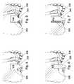
- FIG. 3is a cross-sectional diagram of an embodiment of a drill bit.
- FIG. 4is a cross-sectional diagram of another embodiment of a drill bit.
- FIG. 5is a cross-sectional diagram of another embodiment of a drill bit.
- FIG. 6is a cross-sectional diagram of another embodiment of a drill bit.
- FIG. 8is a cross-sectional diagram of another embodiment of a drill bit.
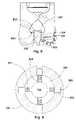
- FIG. 9is a cross-sectional diagram of an embodiment of a steering mechanism
- FIG. 1is a perspective diagram of an embodiment of a drill string 102 suspended by a derrick 101 .
- a bottom-hole assembly 103is located at the bottom of a bore hole 104 and comprises a rotary drag bit 100 .
- the drill string 102may penetrate soft or hard subterranean formations 105 .
- FIGS. 2 through 3disclose a drill bit 100 of the present invention.
- the drill bit 100comprises a shank 200 which is adapted for connection to a down hole tool string such as drill string 102 comprising drill pipe, drill collars, heavy weight pipe, reamers, jars, and/or subs. In some embodiments coiled tubing or other types of tool string may be used.
- the drill bit 100 of the present inventionis intended for deep oil and gas drilling, although any type of drilling application is anticipated such as horizontal drilling, geothermal drilling, mining, exploration, on and off-shore drilling, directional drilling, water well drilling and any combination thereof.
- the bit body 201is attached to the shank 200 and comprises an end which forms a working face 206 .
- blades 202extend outwardly from the bit body 201 , each of which may comprise a plurality of cutting inserts 203 .
- a drill bit 100 most suitable for the present inventionmay have at least three blades 202 ; preferably the drill bit 100 will have between three and seven blades 202 .
- the blades 202collectively form an inverted conical region 303 .
- Each blade 202may have a cone portion 350 , a nose portion 302 , a flank portion 301 , and a gauge portion 300 .
- Cutting inserts 203may be arrayed along any portion of the blades 202 , including the cone portion 350 , nose portion 302 , flank portion 301 , and gauge portion 300 .
- a plurality of nozzles 204are fitted into recesses 205 formed in the working face 206 .
- Each nozzle 204may be oriented such that a jet of drilling mud ejected from the nozzles 204 engages the formation 105 before or after the cutting inserts 203 .
- the jets of drilling mudmay also be used to clean cuttings away from the drill bit 100 .
- the jetsmay be used to create a sucking effect to remove drill bit cuttings adjacent the cutting inserts 203 by creating a low pressure region within their vicinities.
- the jack element 305comprises a hard surface of at least 63 HRc.
- the hard surfacemay be attached to the distal end 307 of the jack element 305 , but it may also be attached to any portion of the jack element 305 .
- the jack element 305may also comprise a cylindrical shaft 306 which is adapted to fit within a bore 304 disposed in the working face 206 of the drill bit 100 .
- the jack element 305may be retained in the bore through the use of at least one retaining element 308 .
- the retaining element 308may comprise a cutting insert 203 , a snap ring, a cap, a sleeve or combinations thereof.
- FIGS. 2 through 3disclose a drill bit 100 that utilizes at least one cutting insert 203 as a retaining element 308 to retain the jack element 305 within the bore 304 .
- At least one of the retaining elementsmay intrude on the diameter by 0.010 to 1 inch.
- the at least one retaining elementmay intrude by 0.300 to 0.700 inches into the bore diameter.
- the retaining elementintrudes by within 5 to 35 percent of the bore diameter.
- the jack element 305is made of the material of at least 63 HRc.
- the jack element 305comprises tungsten carbide with polycrystalline diamond bonded to its distal end 307 .
- the distal end 307 of the jack element 305comprises a diamond or cubic boron nitride surface.
- the diamondmay be selected from group consisting of polycrystalline diamond, natural diamond, synthetic diamond, vapor deposited diamond, silicon bonded diamond, cobalt bonded diamond, thermally stable diamond, polycrystalline diamond with a cobalt concentration of 1 to 40 weight percent, infiltrated diamond, layered diamond, polished diamond, course diamond, fine diamond or combinations thereof.
- the jack element 305is made primarily from a cemented carbide with a binder concentration of 1 to 40 weight percent, preferably of cobalt.
- the working face 206 of the drill bit 100may be made of a steel, a matrix, or a carbide as well.
- the cutting inserts 203 or distal end 307 of the jack element 305may also be made out of hardened steel or may comprise a coating of chromium, titanium, aluminum or combinations thereof.
- cutting inserts 203such as diamond cutting inserts 203 , chip or wear in hard formations 105 when the drill bit 100 is used too aggressively.
- the drillerswill reduce the rotational speed of the bit 100 , but all too often, a hard formation 105 is encountered before it is detected and before the driller has time to react.
- the jack element 305may limit the depth of cut that the drill bit 100 may achieve per rotation in hard formations 105 because the jack element 305 actually jacks the drill bit 100 thereby slowing its penetration in the unforeseen hard formations 105 .
- the formation 105may not be able to resist the weight on bit (WOB) loaded to the jack element 305 and a minimal amount of jacking may take place. But in hard formations 105 , the formation 105 may be able to resist the jack element 305 , thereby lifting the drill bit 100 as the cutting inserts 203 remove a volume of the formation 105 during each rotation. As the drill bit 100 rotates and more volume is removed by the cutting inserts 203 and drilling mud, less WOB will be loaded to the cutting inserts 203 and more WOB will be loaded to the jack element 305 .
- WOBweight on bit
- FIG. 4discloses a drill bit 100 with a bore 304 disposed in the working face 206 .
- the shaft 306 of the jack element 305is disposed within the bore 304 .
- At least one recesshas been formed in the circumference of the bore 304 such that a snap ring may be placed within the bore 304 retaining the shaft 306 within the bore 304 .
- FIG. 5discloses a jack element 305 retained in a bore 304 by a cap retaining element 308 .
- the cap retaining element 308may be threaded, brazed, bolted, riveted or press-fitted to the working surface 206 of the drill bit 100 .
- the surface of the retaining element 308may be complimentary to the jack element 305 .
- the retaining element 308may also have a bearing surface.
- the drill bit bodyis made of steel or matrix.
- the shaft 306may have at least one recess to accommodate the reception of the retaining element 308 .
- the retaining element 308is a snap ring that retains the jack bit 305 in the bore 304 by expanding into the recess formed in the bore 304 and into the recess formed in the shaft 306 .
- a sleevemay be used as a retaining element 308 as disclosed in FIG. 7 .
- the drill bit 100may comprise a plurality of electric motors 800 adapted to alter the axial orientation of the shaft 306 , as in the embodiment of FIGS. 8 and 9 .
- the motors 800may be disposed within recesses 803 formed within the bore 304 wall. They may also be disposed within a collar support secured to the bore 304 wall.
- the plurality of electric motorsmay comprise an AC motor, a universal motor, a stepper motor, a three-phase AC induction motor, a three-phase AC synchronous motor, a two-phase AC servo motor, a single-phase AC induction motor, a single-phase AC synchronous motor, a torque motor, a permanent magnet motor, a DC motor, a brushless DC motor, a coreless DC motor, a linear motor, a doubly- or singly- fed motor, or combinations thereof.
- Each electric motor 800may comprise a protruding threaded pin 801 which extends or retracts according to the rotation of the motor 800 .
- the threaded pin 801may comprise an end element 804 such that the shaft 306 is axially fixed when all of the end elements 804 are contacting the shaft 306 .
- the axial orientation of the shaft 306may be altered by extending the threaded pin 801 of one of the motors 800 and retracting the threaded pin 801 of the other motors 800 . Altering the axial orientation of the shaft 306 may aid in steering the tool string 102 .
- the electric motors 800may be powered by a turbine, a battery, or a power transmission system from the surface or down hole.
- the electric motors 800may also be in communication 802 with a downhole telemetry system.
Landscapes
- Engineering & Computer Science (AREA)
- Life Sciences & Earth Sciences (AREA)
- Geology (AREA)
- Mining & Mineral Resources (AREA)
- Physics & Mathematics (AREA)
- Environmental & Geological Engineering (AREA)
- Fluid Mechanics (AREA)
- General Life Sciences & Earth Sciences (AREA)
- Geochemistry & Mineralogy (AREA)
- Mechanical Engineering (AREA)
- Earth Drilling (AREA)
Abstract
Description
Claims (19)
Priority Applications (1)
| Application Number | Priority Date | Filing Date | Title |
|---|---|---|---|
| US11/774,645US7506706B2 (en) | 2005-11-21 | 2007-07-09 | Retaining element for a jack element |
Applications Claiming Priority (15)
| Application Number | Priority Date | Filing Date | Title |
|---|---|---|---|
| US11/164,391US7270196B2 (en) | 2005-11-21 | 2005-11-21 | Drill bit assembly |
| US11/306,022US7198119B1 (en) | 2005-11-21 | 2005-12-14 | Hydraulic drill bit assembly |
| US11/306,307US7225886B1 (en) | 2005-11-21 | 2005-12-22 | Drill bit assembly with an indenting member |
| US11/306,976US7360610B2 (en) | 2005-11-21 | 2006-01-18 | Drill bit assembly for directional drilling |
| US11/277,394US7398837B2 (en) | 2005-11-21 | 2006-03-24 | Drill bit assembly with a logging device |
| US11/277,380US7337858B2 (en) | 2005-11-21 | 2006-03-24 | Drill bit assembly adapted to provide power downhole |
| US11/278,935US7426968B2 (en) | 2005-11-21 | 2006-04-06 | Drill bit assembly with a probe |
| US11/611,310US7600586B2 (en) | 2006-12-15 | 2006-12-15 | System for steering a drill string |
| US11/673,872US7484576B2 (en) | 2006-03-23 | 2007-02-12 | Jack element in communication with an electric motor and or generator |
| US11/680,997US7419016B2 (en) | 2006-03-23 | 2007-03-01 | Bi-center drill bit |
| US11/686,638US7424922B2 (en) | 2005-11-21 | 2007-03-15 | Rotary valve for a jack hammer |
| US11/737,034US7503405B2 (en) | 2005-11-21 | 2007-04-18 | Rotary valve for steering a drill string |
| US11/750,700US7549489B2 (en) | 2006-03-23 | 2007-05-18 | Jack element with a stop-off |
| US11/759,992US8130117B2 (en) | 2006-03-23 | 2007-06-08 | Drill bit with an electrically isolated transmitter |
| US11/774,645US7506706B2 (en) | 2005-11-21 | 2007-07-09 | Retaining element for a jack element |
Related Parent Applications (3)
| Application Number | Title | Priority Date | Filing Date |
|---|---|---|---|
| US11/278,935Continuation-In-PartUS7426968B2 (en) | 2005-11-21 | 2006-04-06 | Drill bit assembly with a probe |
| US11/750,700Continuation-In-PartUS7549489B2 (en) | 2005-11-21 | 2007-05-18 | Jack element with a stop-off |
| US11/759,992Continuation-In-PartUS8130117B2 (en) | 2005-11-21 | 2007-06-08 | Drill bit with an electrically isolated transmitter |
Related Child Applications (1)
| Application Number | Title | Priority Date | Filing Date |
|---|---|---|---|
| US11/673,872Continuation-In-PartUS7484576B2 (en) | 2005-11-21 | 2007-02-12 | Jack element in communication with an electric motor and or generator |
Publications (2)
| Publication Number | Publication Date |
|---|---|
| US20080011521A1 US20080011521A1 (en) | 2008-01-17 |
| US7506706B2true US7506706B2 (en) | 2009-03-24 |
Family
ID=40442108
Family Applications (1)
| Application Number | Title | Priority Date | Filing Date |
|---|---|---|---|
| US11/774,645Expired - Fee RelatedUS7506706B2 (en) | 2005-11-21 | 2007-07-09 | Retaining element for a jack element |
Country Status (1)
| Country | Link |
|---|---|
| US (1) | US7506706B2 (en) |
Cited By (8)
| Publication number | Priority date | Publication date | Assignee | Title |
|---|---|---|---|---|
| US20090158897A1 (en)* | 2005-11-21 | 2009-06-25 | Hall David R | Jack Element with a Stop-off |
| US20100108385A1 (en)* | 2007-09-06 | 2010-05-06 | Hall David R | Downhole Jack Assembly Sensor |
| US20110048811A1 (en)* | 2005-11-21 | 2011-03-03 | Schlumberger Technology Corporation | Drill bit with a retained jack element |
| US8281882B2 (en) | 2005-11-21 | 2012-10-09 | Schlumberger Technology Corporation | Jack element for a drill bit |
| US8360174B2 (en) | 2006-03-23 | 2013-01-29 | Schlumberger Technology Corporation | Lead the bit rotary steerable tool |
| US8522897B2 (en) | 2005-11-21 | 2013-09-03 | Schlumberger Technology Corporation | Lead the bit rotary steerable tool |
| US8701799B2 (en) | 2009-04-29 | 2014-04-22 | Schlumberger Technology Corporation | Drill bit cutter pocket restitution |
| US12018556B2 (en) | 2018-08-29 | 2024-06-25 | Schlumberger Technology Corporation | Systems and methods of controlling downhole behavior |
Families Citing this family (8)
| Publication number | Priority date | Publication date | Assignee | Title |
|---|---|---|---|---|
| USD620510S1 (en)* | 2006-03-23 | 2010-07-27 | Schlumberger Technology Corporation | Drill bit |
| US9212546B2 (en) | 2012-04-11 | 2015-12-15 | Baker Hughes Incorporated | Apparatuses and methods for obtaining at-bit measurements for an earth-boring drilling tool |
| US9394782B2 (en) | 2012-04-11 | 2016-07-19 | Baker Hughes Incorporated | Apparatuses and methods for at-bit resistivity measurements for an earth-boring drilling tool |
| US9605487B2 (en)* | 2012-04-11 | 2017-03-28 | Baker Hughes Incorporated | Methods for forming instrumented cutting elements of an earth-boring drilling tool |
| US20150047911A1 (en)* | 2013-08-15 | 2015-02-19 | Smith International, Inc. | Using magnetic force/field for drill bits and other cutting tools |
| US10584581B2 (en) | 2018-07-03 | 2020-03-10 | Baker Hughes, A Ge Company, Llc | Apparatuses and method for attaching an instrumented cutting element to an earth-boring drilling tool |
| US11180989B2 (en) | 2018-07-03 | 2021-11-23 | Baker Hughes Holdings Llc | Apparatuses and methods for forming an instrumented cutting for an earth-boring drilling tool |
| USD1034722S1 (en)* | 2024-03-27 | 2024-07-09 | Yuanguo Cheng | PVC pipe reamer |
Citations (5)
| Publication number | Priority date | Publication date | Assignee | Title |
|---|---|---|---|---|
| US3667556A (en)* | 1970-01-05 | 1972-06-06 | John Keller Henderson | Directional drilling apparatus |
| US4836301A (en)* | 1986-05-16 | 1989-06-06 | Shell Oil Company | Method and apparatus for directional drilling |
| US4938297A (en)* | 1987-07-25 | 1990-07-03 | Paul Schmidt | Ram boring machine |
| US5099927A (en)* | 1991-01-28 | 1992-03-31 | Leo J. Barbera | Apparatus for guiding and steering earth boring casing |
| US20040238221A1 (en)* | 2001-07-16 | 2004-12-02 | Runia Douwe Johannes | Steerable rotary drill bit assembly with pilot bit |
- 2007
- 2007-07-09USUS11/774,645patent/US7506706B2/ennot_activeExpired - Fee Related
Patent Citations (5)
| Publication number | Priority date | Publication date | Assignee | Title |
|---|---|---|---|---|
| US3667556A (en)* | 1970-01-05 | 1972-06-06 | John Keller Henderson | Directional drilling apparatus |
| US4836301A (en)* | 1986-05-16 | 1989-06-06 | Shell Oil Company | Method and apparatus for directional drilling |
| US4938297A (en)* | 1987-07-25 | 1990-07-03 | Paul Schmidt | Ram boring machine |
| US5099927A (en)* | 1991-01-28 | 1992-03-31 | Leo J. Barbera | Apparatus for guiding and steering earth boring casing |
| US20040238221A1 (en)* | 2001-07-16 | 2004-12-02 | Runia Douwe Johannes | Steerable rotary drill bit assembly with pilot bit |
Cited By (11)
| Publication number | Priority date | Publication date | Assignee | Title |
|---|---|---|---|---|
| US20090158897A1 (en)* | 2005-11-21 | 2009-06-25 | Hall David R | Jack Element with a Stop-off |
| US20110048811A1 (en)* | 2005-11-21 | 2011-03-03 | Schlumberger Technology Corporation | Drill bit with a retained jack element |
| US8020471B2 (en)* | 2005-11-21 | 2011-09-20 | Schlumberger Technology Corporation | Method for manufacturing a drill bit |
| US8281882B2 (en) | 2005-11-21 | 2012-10-09 | Schlumberger Technology Corporation | Jack element for a drill bit |
| US8522897B2 (en) | 2005-11-21 | 2013-09-03 | Schlumberger Technology Corporation | Lead the bit rotary steerable tool |
| US8950517B2 (en)* | 2005-11-21 | 2015-02-10 | Schlumberger Technology Corporation | Drill bit with a retained jack element |
| US8360174B2 (en) | 2006-03-23 | 2013-01-29 | Schlumberger Technology Corporation | Lead the bit rotary steerable tool |
| US20100108385A1 (en)* | 2007-09-06 | 2010-05-06 | Hall David R | Downhole Jack Assembly Sensor |
| US8499857B2 (en) | 2007-09-06 | 2013-08-06 | Schlumberger Technology Corporation | Downhole jack assembly sensor |
| US8701799B2 (en) | 2009-04-29 | 2014-04-22 | Schlumberger Technology Corporation | Drill bit cutter pocket restitution |
| US12018556B2 (en) | 2018-08-29 | 2024-06-25 | Schlumberger Technology Corporation | Systems and methods of controlling downhole behavior |
Also Published As
| Publication number | Publication date |
|---|---|
| US20080011521A1 (en) | 2008-01-17 |
Similar Documents
| Publication | Publication Date | Title |
|---|---|---|
| US7506706B2 (en) | Retaining element for a jack element | |
| US20110048811A1 (en) | Drill bit with a retained jack element | |
| US7694756B2 (en) | Indenting member for a drill bit | |
| US7258179B2 (en) | Rotary bit with an indenting member | |
| US7533737B2 (en) | Jet arrangement for a downhole drill bit | |
| US8281882B2 (en) | Jack element for a drill bit | |
| US7641003B2 (en) | Downhole hammer assembly | |
| US7624824B2 (en) | Downhole hammer assembly | |
| US7270196B2 (en) | Drill bit assembly | |
| US7484576B2 (en) | Jack element in communication with an electric motor and or generator | |
| EP3540173B1 (en) | Shaped cutting elements for earth boring tools, earth boring tools including such cutting elements, and related methods | |
| US8943663B2 (en) | Methods of forming and repairing cutting element pockets in earth-boring tools with depth-of-cut control features, and tools and structures formed by such methods | |
| US7900720B2 (en) | Downhole drive shaft connection | |
| US7954401B2 (en) | Method of assembling a drill bit with a jack element | |
| GB2389132A (en) | Fixed blade symmetrical hole opener | |
| US9890597B2 (en) | Drill bits and tools for subterranean drilling including rubbing zones and related methods | |
| CN112513405B (en) | Earth-boring tool with gage inserts configured to reduce bit walk and method of drilling with earth-boring tool | |
| US10557318B2 (en) | Earth-boring tools having multiple gage pad lengths and related methods |
Legal Events
| Date | Code | Title | Description |
|---|---|---|---|
| AS | Assignment | Owner name:HALL, DAVID R., MR., UTAH Free format text:ASSIGNMENT OF ASSIGNORS INTEREST;ASSIGNORS:WILDE, TYSON J., MR.;BLACK, BOYD, MR.;LEANY, FRANCIS, MR.;AND OTHERS;REEL/FRAME:019527/0606 Effective date:20070705 | |
| AS | Assignment | Owner name:NOVADRILL, INC.,UTAH Free format text:ASSIGNMENT OF ASSIGNORS INTEREST;ASSIGNOR:HALL, DAVID R.;REEL/FRAME:021701/0758 Effective date:20080806 Owner name:NOVADRILL, INC., UTAH Free format text:ASSIGNMENT OF ASSIGNORS INTEREST;ASSIGNOR:HALL, DAVID R.;REEL/FRAME:021701/0758 Effective date:20080806 | |
| STCF | Information on status: patent grant | Free format text:PATENTED CASE | |
| FEPP | Fee payment procedure | Free format text:PAT HOLDER NO LONGER CLAIMS SMALL ENTITY STATUS, ENTITY STATUS SET TO UNDISCOUNTED (ORIGINAL EVENT CODE: STOL); ENTITY STATUS OF PATENT OWNER: LARGE ENTITY | |
| AS | Assignment | Owner name:SCHLUMBERGER TECHNOLOGY CORPORATION,TEXAS Free format text:ASSIGNMENT OF ASSIGNORS INTEREST;ASSIGNOR:NOVADRILL, INC.;REEL/FRAME:024055/0457 Effective date:20100121 Owner name:SCHLUMBERGER TECHNOLOGY CORPORATION, TEXAS Free format text:ASSIGNMENT OF ASSIGNORS INTEREST;ASSIGNOR:NOVADRILL, INC.;REEL/FRAME:024055/0457 Effective date:20100121 | |
| FEPP | Fee payment procedure | Free format text:PAYOR NUMBER ASSIGNED (ORIGINAL EVENT CODE: ASPN); ENTITY STATUS OF PATENT OWNER: LARGE ENTITY | |
| FPAY | Fee payment | Year of fee payment:4 | |
| FPAY | Fee payment | Year of fee payment:8 | |
| FEPP | Fee payment procedure | Free format text:MAINTENANCE FEE REMINDER MAILED (ORIGINAL EVENT CODE: REM.); ENTITY STATUS OF PATENT OWNER: LARGE ENTITY | |
| LAPS | Lapse for failure to pay maintenance fees | Free format text:PATENT EXPIRED FOR FAILURE TO PAY MAINTENANCE FEES (ORIGINAL EVENT CODE: EXP.); ENTITY STATUS OF PATENT OWNER: LARGE ENTITY | |
| STCH | Information on status: patent discontinuation | Free format text:PATENT EXPIRED DUE TO NONPAYMENT OF MAINTENANCE FEES UNDER 37 CFR 1.362 | |
| FP | Lapsed due to failure to pay maintenance fee | Effective date:20210324 |