US7505890B2 - Hard disk drive emulator - Google Patents
Hard disk drive emulatorDownload PDFInfo
- Publication number
- US7505890B2 US7505890B2US10/342,682US34268203AUS7505890B2US 7505890 B2US7505890 B2US 7505890B2US 34268203 AUS34268203 AUS 34268203AUS 7505890 B2US7505890 B2US 7505890B2
- Authority
- US
- United States
- Prior art keywords
- emulator
- memory
- hdd
- random access
- access memory
- Prior art date
- Legal status (The legal status is an assumption and is not a legal conclusion. Google has not performed a legal analysis and makes no representation as to the accuracy of the status listed.)
- Active, expires
Links
Images


Classifications
- G—PHYSICS
- G06—COMPUTING OR CALCULATING; COUNTING
- G06F—ELECTRIC DIGITAL DATA PROCESSING
- G06F3/00—Input arrangements for transferring data to be processed into a form capable of being handled by the computer; Output arrangements for transferring data from processing unit to output unit, e.g. interface arrangements
- G06F3/06—Digital input from, or digital output to, record carriers, e.g. RAID, emulated record carriers or networked record carriers
- G06F3/0601—Interfaces specially adapted for storage systems
- G06F3/0628—Interfaces specially adapted for storage systems making use of a particular technique
- G06F3/0662—Virtualisation aspects
- G06F3/0664—Virtualisation aspects at device level, e.g. emulation of a storage device or system
- G—PHYSICS
- G06—COMPUTING OR CALCULATING; COUNTING
- G06F—ELECTRIC DIGITAL DATA PROCESSING
- G06F3/00—Input arrangements for transferring data to be processed into a form capable of being handled by the computer; Output arrangements for transferring data from processing unit to output unit, e.g. interface arrangements
- G06F3/06—Digital input from, or digital output to, record carriers, e.g. RAID, emulated record carriers or networked record carriers
- G06F3/0601—Interfaces specially adapted for storage systems
- G06F3/0602—Interfaces specially adapted for storage systems specifically adapted to achieve a particular effect
- G06F3/0614—Improving the reliability of storage systems
- G—PHYSICS
- G06—COMPUTING OR CALCULATING; COUNTING
- G06F—ELECTRIC DIGITAL DATA PROCESSING
- G06F3/00—Input arrangements for transferring data to be processed into a form capable of being handled by the computer; Output arrangements for transferring data from processing unit to output unit, e.g. interface arrangements
- G06F3/06—Digital input from, or digital output to, record carriers, e.g. RAID, emulated record carriers or networked record carriers
- G06F3/0601—Interfaces specially adapted for storage systems
- G06F3/0668—Interfaces specially adapted for storage systems adopting a particular infrastructure
- G06F3/0671—In-line storage system
- G06F3/0673—Single storage device
- G06F3/0679—Non-volatile semiconductor memory device, e.g. flash memory, one time programmable memory [OTP]
Definitions
- the present inventionis related to data storage systems generally, and more specifically to hard disk drive emulators.
- a server bladeis a circuit board populated with the components of a computer, such as a processor, memory (random access and read-only memory), a system bus, a hard disk drive and a network connection.
- Each bladeis an independent system with its own memory, processor and network connection.
- Bladed serversstack numerous independent lower-end servers within a single cabinet. Due to their compact size, multiple blade servers can be placed in a single server rack or enclosure, allowing numerous systems to share electricity and HVAC resources.
- Server bladesare more cost-efficient, smaller and consume less power than traditional box-based servers.
- One source of their appeallies in the fact that they may be inserted in a rack to conserve space.
- one exemplary chassis manufactured by IBMcan hold up to 14 processor blades.
- Six chassiscan fit into a server rack, which could house up to 168 processors, or about double what a rack would house if stuffed with traditional “pizza box” servers.
- Server bladeshave been designed for dedicated applications such as Web servers and caching servers that deliver Web pages to Internet browsers, SSL servers for encrypted communication, streaming servers for audio and video transmissions, running firewalls to keep intruders out of corporate networks, and housing DNS (domain name system) indexes that enable one computer to find another on the Internet.
- SSL serversfor encrypted communication
- streaming serversfor audio and video transmissions
- firewallsto keep intruders out of corporate networks
- housing DNSdomain name system indexes that enable one computer to find another on the Internet.
- server bladesare their scalability. In subscriber service businesses, it is desirable to be able to grow server processing capacity to match increases in the subscriber base. For example, in an interactive television system it is desirable to increase processing in proportion to the number of subscribers (or the expected number of simultaneous subscriber sessions).
- Implicit in the server blade modelis the ability to retain some or all of the existing server blades when a new blade is added.
- the first server blades initially installed in a given rackmay remain in service longer than a traditional unitary server. Therefore, a method of increasing the lifecycle of a server blade is advantageous.
- the use of “blade” serverswill potentially increase the number of computers to be maintained in many facilities by orders of magnitude. For example, as noted above, more than one hundred blades can be installed in the space of a traditional server.
- the administrator of the blade serverhas to maintain the hardware and software in each blade. Because of the number of blades in a system can far exceed the number of traditional servers they replace, methods for improving the reliability of a server blade are also advantageous.
- the main mechanical component (and likely point of failure) of a server bladeis the hard disk drive (HDD), which provides the main non-volatile mass storage.
- HDDhard disk drive
- Typical commercially available HDDsinclude a disk that spins at a speed of 7200 revolutions per minute. The disks rotate on bearings, which are prone to failure.
- a hard disk drive (HDD) emulatorcomprises a dynamic random access memory, a controller that refreshes content of the dynamic random access memory, and an input/output port coupled to the controller.
- the input/output portprovides a hard disk drive interface.
- An operating system of a computing system in which the HDD emulator is installeduses the dynamic random access memory as a swap storage space.
- FIG. 1is a block diagram of an exemplary HDD emulator.
- FIG. 2is a block diagram showing the DRAM controller and DRAM of FIG. 1 .
- FIG. 3is a block diagram of a server blade containing the HDD emulator of FIG. 1 .
- FIG. 4is a block diagram of a server including the server blade of FIG. 3 .
- FIG. 5is a block diagram of a cable system, including a cable headend having the server of FIG. 4 and a set top box that having the HDD emulator of FIG. 1 .
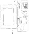
- FIG. 6is a diagram of a standalone computer including the HDD emulator of FIG. 1 .
- FIG. 1is a block diagram of an exemplary hard disk drive (HDD) emulator 12 .
- the HDD emulator 12includes a dynamic random access memory (DRAM) 18 and a controller 20 that refreshes content of the DRAM. At least part of the DRAM 18 of the HDD emulator 12 is used as the swap storage space of a virtual memory system.
- DRAMdynamic random access memory
- HDD emulator 12provides a standard HDD physical and electrical interface 42 , capable of communicating with any processor (e.g., processor 32 shown in FIG. 2 ) that is otherwise configured to communicate with a hard disk drive.
- HDD emulator 12has an input/output port 42 coupled to the HDD emulator controller 20 .
- the input/output port 42provides the physical hard disk drive interface.
- the input/output port 42is an integrated drive electronics (IDE) connector, such as those used in advanced technology attachment (e.g., ATA/66, ATA/100) disk drives.
- IDEintegrated drive electronics
- the connectorcomplies with the small computer system interface (SCSI) standard used in many APPLETM and UNIX systems.
- the connectorcomplies with the universal serial bus (USB) interface standard.
- Other embodimentsinclude other types of connectors corresponding to other interfaces suitable, for high speed data transfer.
- HDD emulator 12Use of a standard connector interface allows HDD emulator 12 to be connected to a server blade, a unitary server, a desktop computer, a laptop computer, or other type of computer.
- the HDD emulator 12may alternatively be connected to the processor of a television set top box used to receive and process cable or satellite television signals.
- Virtual memorymay be viewed as an imaginary memory area supported by operating systems such as Windows, OS/2 and UNIX. Virtual memory may also be viewed as an alternate set of memory addresses. Programs use these virtual addresses rather than real addresses to store instructions and data. When the program is executed, the virtual addresses are translated (mapped) into physical memory addresses. Virtual memory essentially enlarges the usable physical address space, the set of addresses a program can use. For example, virtual memory might contain two to four times as many addresses as main memory. A program larger than the main memory would not be able to fit in main memory all at once, but the computer could execute such a program by copying into main memory those portions of the program needed at any given point during execution.
- the operating systemdivides virtual memory into pages, each of which contains a fixed number of addresses. Each page is stored on a mass storage medium. When the page is needed in the main memory, the operating system copies (swaps) it from mass storage medium to main physical memory, translating (mapping) the virtual addresses into real addresses.
- the mass storage medium for the swap partitionis implemented in solid state devices within the HDD emulator 12 .
- the swap directory and swap dataare stored in DRAM 18 .
- the DRAM 18may include any commercially available DRAM devices, such as individual RAM chips, or a printed circuit board with memory devices mounted thereon, such as a single in-line memory module (SIMM), a dual in-line memory module (DIMM), or Rambus memory module (RIMM).
- the memorymay be of any variety, such as Extended Data Output DRAM (EDO DRAM), Burst EDO DRAM, Fast Page Mode RAM (FPM RAM), Synchronous DRAM (SDRAM), Mobile SDRAM, Rambus DRAM (RDRAM), or SyncLink DRAM (SLDRAM). Other memory chips or other types of circuit boards having memory mounted thereon may be used.
- One of ordinary skill in the artcan readily set the location of the swap partition of the virtual memory using conventional operating system functions. For example, in a WINDOWS 98 operating environment, a partition can be created in the HDD Emulator 12 using the standard FDISK routine. Then, under the “Performance” tab of the WINDOWS 98 system properties dialog box, a “Virtual Memory” button is provided to set virtual memory parameters. In the “Virtual Memory” dialog box, the drive letter of the HDD emulator is specified. Because HDD Emulator 12 has an input/output interface 42 that conforms to that of a standard HDD, one of ordinary skill can readily determine the procedure for setting the swap partition in the HDD emulator for other operating systems using virtual memory.
- the HDD emulator 12can be partitioned to establish separate partitions for the SRAM 14 and Flash EEPROM 16 .
- the total amount of DRAM 18 in HDD emulator 12is at least about four times as large as the main memory 36 of the processor system in which the HDD emulator is installed.
- the HDD emulatorpreferably has at least 2.0 GB of DRAM 18 for swap space.
- the DRAM 18may optionally include error correction coding (ECC) memory devices or non-ECC memory devices.
- ECC memory deviceshave extra bytes, which are used with special circuitry for testing the accuracy of data as it passes in and out of memory.
- ECC memorythe memory cells that are provided for storing error correction codes are used for storing additional swap data, as described further below.
- Other embodimentsuse the ECC circuitry provided by the manufacturer for word error correction, although the efficiency of memory usage is not as great.
- DRAMcombines high access speed and high reliability with low cost relative to non-volatile solid state memory media, and is advantageous for any application that does not require non-volatile storage.
- HDD emulator 12further includes at least one additional non-volatile solid-state storage medium for persistent storage.
- an electrically erasable programmable read only memory (EEPROM) or flash EEPROM 16is used to store a boot operating system, and optionally, one or more application programs. Both EEPROM and flash EEPROM can be erased by exposing them to an electrical charge. A flash EEPROM can be erased and reprogrammed in blocks instead of one byte at a time, and is thus faster than an EEPROM. Like other types of PROM, EEPROM and flash EEPROM retain their contents even when the power is turned off, but they are not as fast as RAM (in either storage or retrieval).
- EEPROM and flash EEPROMare subject to “wear,” or degradation after many repeated write cycles. Flash chips generally have lifespans from 100K to 300K write cycles. Therefore, flash EEPROMs are preferred for storing types of data that are updated relatively-infrequently, but are not preferred for a swap partition.
- HDD emulator 12further includes a non-wearable, non-volatile memory device that does not degrade, even after frequent writes.
- some embodimentsinclude a non-volatile static random access memory (SRAM) 14 with a battery for backup power.
- the emulator controller 20causes the non-volatile SRAM 14 to store at least one of the group consisting of partition information and file directory information.
- the partition informationidentifies the location of the swap partition in DRAM, allowing the operating system to swap data between the virtual memory and the real memory.
- Non-volatile SRAMcombines fast access speed (even faster than DRAM) and high reliability with persistence of memory.
- SRAM 14may also be used to provide a high speed cache for pages that are likely to be swapped to main memory in the near future, using a conventional cache management algorithm.
- HDD emulator controller 20also includes cache controller logic.
- magnetoresistive RAMis used for the non-wearable non-volatile memory device 14 .
- This technologyhas the nonvolatility characteristic of flash memory and the advantage of DRAM density (without the need for refresh). MRAM has speed that is comparable to SRAM.
- MRAMmay also be used for storing the partition information and file directories, in place of flash EEPROM.
- the DRAM 18includes one or more ECC memory DIMMs.
- ECCerror correction mechanism
- One exemplary embodimenttakes advantage of the way whole pages (instead of individual words) of data are swapped from the virtual memory into the real memory by using a more space efficient error correction mechanism than the ECC provides. (ECC is provided on a word basis.)
- no error correction codesare applied to individual words in DRAM 18 , because the words of data are not accessed individually for swapping.
- an error correction algorithmis applied to the whole page, or to a block (e.g., 256 bytes or 512 bytes) that is a subset of the page, to produce block error correction codes stored in a portion 18 b of DRAM 18 .
- the total number of bytes that are allocated to error correction codes in portion 18 bis less than the total number that would be allocated to ECC in cells 18 c if word-wise error correction is employed. As a consequence, many ECC memory cells 18 c are freed up from being used for error correction, and are made available for swap storage purposes. For example, a conventional cyclical redundancy code (CRC) may be used for block error encoding and correction. When the data are refreshed in the DRAM 18 , the block CRC is also read and used to restore any bits that have become corrupted.
- CRCcyclical redundancy code
- the controller 20includes a hard drive emulator controller, and a DRAM controller 22 that controls the DRAM 18 .
- the controllers 20 and 22may be implemented as two separate devices, or as a single controller that performs two functions.
- FIG. 2shows the operation of DRAM controller 22 .
- FIG. 2shows one block of protected data in memory cells 18 a and 18 c , with corresponding error correction codes in memory cells 18 b .
- the DRAM controller 22causes the DRAM 18 to store swapped data in both the data storage cells 18 a and the ECC cells 18 c.
- the controllerreceives four bytes of data to be stored in DRAM and ECC circuitry generates an additional byte of ECC. Then the controller sends the four bytes of data to the storage cells and the one byte of ECC to the ECC cells of the DRAM. Similarly, when the four bytes of data are requested by the processor, the conventional controller reads the four bytes of data and the one byte of ECC, to ensure data integrity. In the embodiment of FIG. 2 , however, a byte of the data base is not needed for ECC, so the full bandwidth of the data bus 23 is used to carry data, and there is no need to store ECC for each word. All memory cells in DRAM 18 can be treated the same, in terms of availability to store data.
- DRAM controller 22also includes a function 22 a that performs error correction coding on a block level (instead of word-by-word) using a block level algorithm, and a regeneration circuit 22 b that sweeps through data blocks checking and correcting errors in blocks, based on the block error correction codes generated by function 22 a .
- the dataare stored in the DRAM in data blocks, which include data written in the storage cells 18 a and the memory cells 18 c that would be used for error correction codes if the DRAM 18 were controlled by a conventional memory controller (not shown).
- the block ECC memory cells 18 boccupy a smaller total portion of the DRAM 18 than the total of all the ECC memory cells 18 c.
- FIG. 2shows the block ECC data being stored in memory cells 18 b that are separate from the memory cells 18 c previously allocated for ECC, this is for ease of illustration only.
- the DRAM controller 22may store the block error correction codes in some of the memory cells 18 a previously allocated for data, in some of the memory cells 18 c previously allocated for ECC, or in any combination of the two. Even if the DRAM controller 22 causes the block error correction codes to be written solely within memory cells 18 c previously allocated for ECC, the block error correction codes do not occupy all of the memory cells 18 c.
- FIG. 2shows a five-byte data bus connecting the DRAM controller 22 to the DRAM 18 , this is only an example. The technique described above may be used with any bus.
- FIG. 2shows a temperature sensor 19 on the memory module, adjacent to one of the memory chips.
- the temperature of the DRAMis sensed and provided to the regeneration circuit 22 b .
- the regeneration circuitcan then dynamically adjust the refresh rate based on the temperature.
- the charge in each memory celldissipates more quickly when the temperature is higher, and more slowly when the temperature is lower.
- regeneration circuit 22 breduces the refresh rate when the sensed temperature is lower, to conserve power.
- the DRAM controller 22has knowledge of which portions of the DRAM are in use. In a conventional main memory, data (or instructions) that are recently used are likely to be used again presently. However, when a page is swapped back from virtual memory to main memory, there is no longer a need to keep a copy of the data in the swap partition. With knowledge of which portions of the DRAM 18 are in use, and which are no longer needed, the regeneration circuit 22 b can conserve power by only refreshing the areas of DRAM 18 currently being used.
- the selective refreshing of only currently used memory cellsis combined with the temperature dependent refresh rate to further conserve power.
- the exemplary HDD emulator 12is substituted for a hard disk drive in many applications, providing improved performance and reliability.
- the HDD emulator 12resides alongside a regular HDD as an additional drive for swap storage. In these embodiments, swap performance is improved, and hard drive wear is reduced, improving overall reliability.
- FIG. 3is a diagram of an exemplary server blade 30 including the HDD emulator 12 on board.
- the server blade 30includes a processor 32 , a main memory 36 , a hard disk drive (HDD) controller 40 coupled to the processor 32 , BIOS 34 , and an HDD emulator 12 .
- HDDhard disk drive
- HDD emulator 12has solid state memory including dynamic random access memory 18 and a DRAM controller 22 that refreshes the DRAM 18 .
- the operating system of server blade 30uses at least a portion of the DRAM 18 as a swap storage space.
- the emulator controller 20is communicatively coupled to the HDD controller 40 .
- the HD controller 40has a conventional port (e.g., ATA/100 or Wide Ultra3 SCSI), and emulator 12 has a corresponding mating connector 42 , as described above with reference to FIG. 1 .
- one of the group consisting of the HDD emulator 12 and the HDD controller 40has a printed circuit board with conductive pads on its edge, and the other of the group consisting of the HDD emulator 12 and the HDD controller 40 has a clip for receiving the circuit board to form the HDD interface.
- the processor 32may be of any type suitable for a server blade including, but not limited to, a 2.8 GHz single or dual XeonTM processor or a 1.4 GHz Pentium® III (dual capability) processor, both manufactured by Intel Corporation of Santa Clara, Calif.
- Exemplary main server blade memory 36may be of any type suitable for a server blade including, but not limited to, between 512 MB and 2 GB of ECC SDRAM.
- the network controller 38may be, for example, an Ethernet network interface card (NIC), such as a Fast Ethernet PCI controller GD82559ER with Wake On LAN feature, by Intel Corporation, or an NC3 163 10/100 Mbps Fast Ethernet adapter with Wake On LAN feature, or an NC7780 gigabit Ethernet NIC, marketed by Hewlett Packard of Palo Alto, Calif. Other network interface cards may be used.
- NICEthernet network interface card
- NICEthernet network interface card
- An on board basic I/O system (BIOS) memory 34may include a flash EEPROM, allowing updates to the BIOS. In alternative embodiments, MRAM or a read only memory may be used. For the server blade, a net-bootable BIOS may be used to load on boot operating system and applications into the server 44 .
- BIOSbasic I/O system
- FIG. 4shows an example of a server 44 including a plurality of server blades 30 , at least one of which has an HDD emulator 12 .
- all of the server blades 30have HDD emulators 12 .
- a single servermay alternatively contain a first set of server blades 30 , each of which has an HDD emulator 12 , and a second set of server blades, each having a conventional HDD (not shown).
- the improved server blade 12may be added to an existing server 44 that already includes one or more conventional server blades with real hard disk drives.
- one or more of the server bladesmay be configured with both an HDD emulator 12 and an HDD.
- FIG. 5is a block diagram of a CATV system including the server 44 of FIG. 4 .
- the server 44is included in a cable headend facility 50 .
- the headend 50is the control center of a CATV system, where incoming signals are amplified, converted, processed, and combined into a common cable for transmission to customers.
- Conventional headend componentssuch as antennas, preamplifiers, frequency converters, demodulators, modulators, processors, and other related equipment are understood by those of ordinary skill in the art to be present, but are omitted in FIG. 5 for brevity.
- the Headend 50transmits interactive television (ITV) programs to a plurality of television set top boxes 60 (only one of which is shown in FIG. 5 .).
- the server 44maintains data for each active thin client session in main memory 36 .
- the server 44renders web pages that are viewed by the clients. Till the next request from the thin client, the user's session in the headend 50 is suspended, and the user's session can all be swapped to HDD emulator 12 .
- HDD emulator 12can store data from a plurality of suspended thin client sessions 118 . This allows the server memory to be used for another session with an active user.
- a set top box 60having a thin client application for presenting the data rendered by the server 44 .
- the server 44is coupled by a broad-band cable 64 system to at least one thin client application of the set top box 60 , and the server serves interactive applications to the thin client.
- the cable (and satellite) television industryis an advantageous application of an HDD emulator 12 that uses DRAM memory 18 for swap space. There is no requirement to restore the information in the server swap pages after loss of power. These areas contain dynamic information.
- the swap data 118may have copies of inactive session data pertaining to a session with a set top box 60 . A new session can be established with the user, and thus persistent storage is not required.
- the cable industryis also one in which server computing needs scale to the number of active customer sessions, making the bladed server model useful.
- FIG. 6shows another example, in which a computer system 80 comprises a general purpose processor 82 with main memory 86 configured to run an operating system supporting virtual memory 87 .
- Computer 80has a hard drive emulator 12 , as shown in FIG. 1 , including dynamic random access memory 18 , and means 20 , 22 for controlling the dynamic random access memory, so that a swap partition of the virtual memory is located in the dynamic random access memory, to support virtual memory operations of the operating system.
- the computer 80may have a hard disk drive 89 .
- the use of an HDD emulator for swap storageimproves swap performance and reduces wear on the HDD 89 .
- the HDD emulator 12can be used in any processor based system having an operating system that manages virtual memory by setting up a specific swap area in a hard drive, by redirecting the swap area to the HDD emulator.
- the HDD emulator 12can be used in virtually any computer to improve reliability and performance by elimination of the mechanical hard drive.
Landscapes
- Engineering & Computer Science (AREA)
- Theoretical Computer Science (AREA)
- Human Computer Interaction (AREA)
- Physics & Mathematics (AREA)
- General Engineering & Computer Science (AREA)
- General Physics & Mathematics (AREA)
- Techniques For Improving Reliability Of Storages (AREA)
Abstract
Description
Claims (23)
Priority Applications (1)
| Application Number | Priority Date | Filing Date | Title |
|---|---|---|---|
| US10/342,682US7505890B2 (en) | 2003-01-15 | 2003-01-15 | Hard disk drive emulator |
Applications Claiming Priority (1)
| Application Number | Priority Date | Filing Date | Title |
|---|---|---|---|
| US10/342,682US7505890B2 (en) | 2003-01-15 | 2003-01-15 | Hard disk drive emulator |
Publications (2)
| Publication Number | Publication Date |
|---|---|
| US20040138868A1 US20040138868A1 (en) | 2004-07-15 |
| US7505890B2true US7505890B2 (en) | 2009-03-17 |
Family
ID=32711777
Family Applications (1)
| Application Number | Title | Priority Date | Filing Date |
|---|---|---|---|
| US10/342,682Active2026-05-08US7505890B2 (en) | 2003-01-15 | 2003-01-15 | Hard disk drive emulator |
Country Status (1)
| Country | Link |
|---|---|
| US (1) | US7505890B2 (en) |
Cited By (11)
| Publication number | Priority date | Publication date | Assignee | Title |
|---|---|---|---|---|
| US20060184349A1 (en)* | 2004-12-10 | 2006-08-17 | Goud Gundrala D | Method and apparatus for providing virtual server blades |
| US20080270633A1 (en)* | 2004-10-29 | 2008-10-30 | International Business Machines Corporation | Shared simultaneously-connected drives |
| US20090171650A1 (en)* | 2007-12-27 | 2009-07-02 | Unity Semiconductor Corporation | Non-Volatile memories in interactive entertainment systems |
| US20110145493A1 (en)* | 2008-08-08 | 2011-06-16 | Jung Ho Ahn | Independently Controlled Virtual Memory Devices In Memory Modules |
| US8484536B1 (en)* | 2010-03-26 | 2013-07-09 | Google Inc. | Techniques for data storage, access, and maintenance |
| US8601339B1 (en) | 2010-06-16 | 2013-12-03 | Google Inc. | Layered coding techniques for data storage |
| US8615698B1 (en) | 2011-09-28 | 2013-12-24 | Google Inc. | Skewed orthogonal coding techniques |
| US8621317B1 (en) | 2011-07-25 | 2013-12-31 | Google Inc. | Modified orthogonal coding techniques for storing data |
| US8856619B1 (en) | 2012-03-09 | 2014-10-07 | Google Inc. | Storing data across groups of storage nodes |
| CN110888599A (en)* | 2013-12-19 | 2020-03-17 | 索尼互动娱乐有限责任公司 | Interface device, system for virtualizing mass storage |
| US11409601B1 (en)* | 2021-01-26 | 2022-08-09 | Micron Technology, Inc. | Memory device protection |
Families Citing this family (26)
| Publication number | Priority date | Publication date | Assignee | Title |
|---|---|---|---|---|
| US7127602B1 (en)* | 2003-02-21 | 2006-10-24 | Cisco Technology, Inc. | iSCSI computer boot system and method |
| US7363356B1 (en) | 2003-03-24 | 2008-04-22 | Cisco Technology, Inc. | Boot modification of registry data for iSCSI network boot operations |
| US7360072B1 (en)* | 2003-03-28 | 2008-04-15 | Cisco Technology, Inc. | iSCSI system OS boot configuration modification |
| US7496492B2 (en)* | 2003-08-29 | 2009-02-24 | Microsoft Corporation | Software-aided storage device emulation in a physical storage device |
| US7428689B2 (en)* | 2005-08-30 | 2008-09-23 | Infineon Technologies Ag | Data memory system and method for transferring data into a data memory |
| US7752391B2 (en)* | 2006-01-20 | 2010-07-06 | Apple Inc. | Variable caching policy system and method |
| EP1923786A1 (en)* | 2006-11-14 | 2008-05-21 | NEC Electronics Corporation | Volatile memory device and data integrity |
| US20080294421A1 (en)* | 2007-05-23 | 2008-11-27 | Kwok-Yan Leung | Hard Disk Drive Adapter For Emulating Hard Disk Drive Interface |
| EP2012202A1 (en)* | 2007-07-06 | 2009-01-07 | Sysopen Digia Oyj | Measurement device emulates a mass storage device |
| US7990762B2 (en)* | 2008-02-06 | 2011-08-02 | Unity Semiconductor Corporation | Integrated circuits to control access to multiple layers of memory |
| WO2011021174A2 (en)* | 2009-08-21 | 2011-02-24 | Xdata Engineering Limited | Storage peripheral device emulation |
| US8688776B1 (en)* | 2009-12-29 | 2014-04-01 | The Directv Group, Inc. | Emulation tool and method of using the same for a content distribution system |
| US8166244B2 (en)* | 2010-03-12 | 2012-04-24 | Sandisk Il Ltd. | Emulating a computer system on a removable storage device |
| US9158726B2 (en) | 2011-12-16 | 2015-10-13 | Inphi Corporation | Self terminated dynamic random access memory |
| US8949473B1 (en)* | 2012-02-16 | 2015-02-03 | Inphi Corporation | Hybrid memory blade |
| US9230635B1 (en) | 2012-03-06 | 2016-01-05 | Inphi Corporation | Memory parametric improvements |
| US9785350B2 (en) | 2013-02-21 | 2017-10-10 | Seagate Technology Llc | Data storage device having a virtual machine |
| US10248940B1 (en)* | 2015-09-24 | 2019-04-02 | Square, Inc. | Modular firmware for transaction system |
| DE102016105661A1 (en)* | 2016-03-29 | 2017-10-05 | BLANKOM systems GmbH | Modular cable head and module for it |
| US10108412B2 (en) | 2016-03-30 | 2018-10-23 | Square, Inc. | Blocking and non-blocking firmware update |
| US11010765B2 (en) | 2016-06-29 | 2021-05-18 | Square, Inc. | Preliminary acquisition of payment information |
| US10417628B2 (en) | 2016-06-29 | 2019-09-17 | Square, Inc. | Multi-interface processing of electronic payment transactions |
| US10817869B2 (en) | 2016-06-29 | 2020-10-27 | Square, Inc. | Preliminary enablement of transaction processing circuitry |
| US10762196B2 (en) | 2018-12-21 | 2020-09-01 | Square, Inc. | Point of sale (POS) systems and methods with dynamic kernel selection |
| US11049095B2 (en) | 2018-12-21 | 2021-06-29 | Square, Inc. | Point of sale (POS) systems and methods with dynamic kernel selection |
| US10990969B2 (en) | 2018-12-21 | 2021-04-27 | Square, Inc. | Point of sale (POS) systems and methods for dynamically processing payment data based on payment reader capability |
Citations (24)
| Publication number | Priority date | Publication date | Assignee | Title |
|---|---|---|---|---|
| US5077737A (en)* | 1989-08-18 | 1991-12-31 | Micron Technology, Inc. | Method and apparatus for storing digital data in off-specification dynamic random access memory devices |
| US5493574A (en)* | 1992-09-24 | 1996-02-20 | Zilog, Inc. | Power efficient RAM disk and a method of emulating a rotating memory disk |
| US5867686A (en)* | 1993-11-09 | 1999-02-02 | Conner; Kenneth H. | High speed real-time information storage system |
| US5974547A (en)* | 1998-03-20 | 1999-10-26 | 3Com Corporation | Technique for reliable network booting of an operating system to a client computer |
| US6169687B1 (en)* | 1995-04-21 | 2001-01-02 | Mark B. Johnson | High density and speed magneto-electronic memory for use in computing system |
| US20010001158A1 (en)* | 1998-12-30 | 2001-05-10 | Tetrick Raymond S. | Memory array organization |
| US6238290B1 (en)* | 1995-08-28 | 2001-05-29 | Mediaone Group, Inc. | System and method for scheduled delivery of a software program over a cable network |
| US6353910B1 (en)* | 1999-04-09 | 2002-03-05 | International Business Machines Corporation | Method and apparatus for implementing error correction coding (ECC) in a dynamic random access memory utilizing vertical ECC storage |
| US20020129204A1 (en)* | 2001-03-06 | 2002-09-12 | Lance Leighnor | Hypercache RAM based disk emulation and method |
| US20020154543A1 (en)* | 2000-02-17 | 2002-10-24 | Conley Kevin M. | Flash EEPROM system with simultaneous multiple data sector programming and storage of physical block characteristics in other designated blocks |
| US20030110351A1 (en)* | 2001-12-07 | 2003-06-12 | Dell Products L.P. | System and method supporting virtual local data storage |
| US20030149700A1 (en)* | 2002-02-05 | 2003-08-07 | Bolt Thomas B. | Emulated backup tape drive using data compression |
| US20030181168A1 (en)* | 1997-08-05 | 2003-09-25 | Allan Herrod | Terminal with optical reader for locating products in a retail establishment |
| US20030200379A1 (en)* | 2002-04-18 | 2003-10-23 | Hollingsworth Robert E. | Bootable solid state floppy disk drive |
| US20030200290A1 (en)* | 2002-04-18 | 2003-10-23 | Myron Zimmerman | System for and method of streaming data to a computer in a network |
| US6654816B1 (en)* | 2000-05-31 | 2003-11-25 | Hewlett-Packard Development Company, L.P. | Communication interface systems for locally analyzing computers |
| US6701450B1 (en)* | 1998-08-07 | 2004-03-02 | Stephen Gold | System backup and recovery |
| US20040054689A1 (en)* | 2002-02-25 | 2004-03-18 | Oak Technology, Inc. | Transcoding media system |
| US20040080988A1 (en)* | 1989-04-13 | 2004-04-29 | Sandisk Corporation | Flash EEprom system |
| US20040093373A1 (en)* | 2002-11-13 | 2004-05-13 | Hansen Peter A. | Method and apparatus for providing virtual devices |
| US20040097288A1 (en)* | 2002-11-14 | 2004-05-20 | Sloate Jim A. | Multiplexed secure video game play distribution |
| US20040098244A1 (en)* | 2002-11-14 | 2004-05-20 | Imation Corp. | Method and system for emulating tape storage format using a non-tape storage medium |
| US20040194086A1 (en)* | 2002-03-20 | 2004-09-30 | National Inst. Of Advanced Ind. Science And Tech. | Suspend and resume method of computer job |
| US7117421B1 (en)* | 2002-05-31 | 2006-10-03 | Nvidia Corporation | Transparent error correction code memory system and method |
- 2003
- 2003-01-15USUS10/342,682patent/US7505890B2/enactiveActive
Patent Citations (24)
| Publication number | Priority date | Publication date | Assignee | Title |
|---|---|---|---|---|
| US20040080988A1 (en)* | 1989-04-13 | 2004-04-29 | Sandisk Corporation | Flash EEprom system |
| US5077737A (en)* | 1989-08-18 | 1991-12-31 | Micron Technology, Inc. | Method and apparatus for storing digital data in off-specification dynamic random access memory devices |
| US5493574A (en)* | 1992-09-24 | 1996-02-20 | Zilog, Inc. | Power efficient RAM disk and a method of emulating a rotating memory disk |
| US5867686A (en)* | 1993-11-09 | 1999-02-02 | Conner; Kenneth H. | High speed real-time information storage system |
| US6169687B1 (en)* | 1995-04-21 | 2001-01-02 | Mark B. Johnson | High density and speed magneto-electronic memory for use in computing system |
| US6238290B1 (en)* | 1995-08-28 | 2001-05-29 | Mediaone Group, Inc. | System and method for scheduled delivery of a software program over a cable network |
| US20030181168A1 (en)* | 1997-08-05 | 2003-09-25 | Allan Herrod | Terminal with optical reader for locating products in a retail establishment |
| US5974547A (en)* | 1998-03-20 | 1999-10-26 | 3Com Corporation | Technique for reliable network booting of an operating system to a client computer |
| US6701450B1 (en)* | 1998-08-07 | 2004-03-02 | Stephen Gold | System backup and recovery |
| US20010001158A1 (en)* | 1998-12-30 | 2001-05-10 | Tetrick Raymond S. | Memory array organization |
| US6353910B1 (en)* | 1999-04-09 | 2002-03-05 | International Business Machines Corporation | Method and apparatus for implementing error correction coding (ECC) in a dynamic random access memory utilizing vertical ECC storage |
| US20020154543A1 (en)* | 2000-02-17 | 2002-10-24 | Conley Kevin M. | Flash EEPROM system with simultaneous multiple data sector programming and storage of physical block characteristics in other designated blocks |
| US6654816B1 (en)* | 2000-05-31 | 2003-11-25 | Hewlett-Packard Development Company, L.P. | Communication interface systems for locally analyzing computers |
| US20020129204A1 (en)* | 2001-03-06 | 2002-09-12 | Lance Leighnor | Hypercache RAM based disk emulation and method |
| US20030110351A1 (en)* | 2001-12-07 | 2003-06-12 | Dell Products L.P. | System and method supporting virtual local data storage |
| US20030149700A1 (en)* | 2002-02-05 | 2003-08-07 | Bolt Thomas B. | Emulated backup tape drive using data compression |
| US20040054689A1 (en)* | 2002-02-25 | 2004-03-18 | Oak Technology, Inc. | Transcoding media system |
| US20040194086A1 (en)* | 2002-03-20 | 2004-09-30 | National Inst. Of Advanced Ind. Science And Tech. | Suspend and resume method of computer job |
| US20030200290A1 (en)* | 2002-04-18 | 2003-10-23 | Myron Zimmerman | System for and method of streaming data to a computer in a network |
| US20030200379A1 (en)* | 2002-04-18 | 2003-10-23 | Hollingsworth Robert E. | Bootable solid state floppy disk drive |
| US7117421B1 (en)* | 2002-05-31 | 2006-10-03 | Nvidia Corporation | Transparent error correction code memory system and method |
| US20040093373A1 (en)* | 2002-11-13 | 2004-05-13 | Hansen Peter A. | Method and apparatus for providing virtual devices |
| US20040097288A1 (en)* | 2002-11-14 | 2004-05-20 | Sloate Jim A. | Multiplexed secure video game play distribution |
| US20040098244A1 (en)* | 2002-11-14 | 2004-05-20 | Imation Corp. | Method and system for emulating tape storage format using a non-tape storage medium |
Non-Patent Citations (8)
| Title |
|---|
| "Bladed Supercomputing Cluster", HiServer(TM) 420, Nexcom, www.nexcom/com.tw/product/bladeserver/hiserver420/, Dec. 3, 2002, pp. 1-3. |
| "Server blade", The Center for Nanoelectronics Business, http://webopedia.com/TERMS/s/server-blade.html, Nov. 11, 2002, pp. 1-2. |
| "The Skinny on Server Blades", ServerWatch(TM), www.serverwatch.com/tutorials/article/php/1355111, Nov. 11, 2002, pp. 1-15. |
| Dram Mobile SDRAM, Samsung Electronic, www.samsungelectronics.com/semiconductors/cram/mobile-dram/mobile-dram.htm, Dec. 4, 2002, pp. 1-2. |
| Neel, D., "Transforming the datacenter", InfoWorld, http://staging.infoworld.com/articles/fe/xml/02/-1/28/020128feedge.xml?Template+/stor, Nov. 11, 2002, pp. 1-3. |
| ProLiant BL p-Class, Quick Specs, http://h18000.www1.hp.com/products/quickspecs/11411-div/11411-div.html, Dec. 2, 2002, pp. 1-46. |
| Spintronics-MRAM, Motorola, www.motorola.colm/content/0,1037,296,00.html, Nov. 27, 2002, pp. 1-2. |
| Wong, W., "Flash-based Microcontrollers are rapidly taking charge", Electronic Design, Nov. 25, 2002, pp. 53-56. |
Cited By (21)
| Publication number | Priority date | Publication date | Assignee | Title |
|---|---|---|---|---|
| US20080270633A1 (en)* | 2004-10-29 | 2008-10-30 | International Business Machines Corporation | Shared simultaneously-connected drives |
| US20080288685A1 (en)* | 2004-10-29 | 2008-11-20 | International Business Machines Corporation | Shared simultaneously-connected drives |
| US7647431B2 (en)* | 2004-10-29 | 2010-01-12 | International Business Machines Corporation | Shared simultaneously-connected removable drives and servers each housing an I/O controller which maintains an uninterrupted protocol connection |
| US7657665B2 (en)* | 2004-10-29 | 2010-02-02 | International Business Machines Corporation | Shared simultaneously-connected removable drives and servers each housing an I/O controller which maintains an uninterrupted protocol connection |
| US7694298B2 (en)* | 2004-12-10 | 2010-04-06 | Intel Corporation | Method and apparatus for providing virtual server blades |
| US20100318993A1 (en)* | 2004-12-10 | 2010-12-16 | Goud Gundrala D | Method and apparatus for providing virtual server lades |
| US20060184349A1 (en)* | 2004-12-10 | 2006-08-17 | Goud Gundrala D | Method and apparatus for providing virtual server blades |
| US20090171650A1 (en)* | 2007-12-27 | 2009-07-02 | Unity Semiconductor Corporation | Non-Volatile memories in interactive entertainment systems |
| US8788747B2 (en)* | 2008-08-08 | 2014-07-22 | Hewlett-Packard Development Company, L.P. | Independently controlled virtual memory devices in memory modules |
| US20110145493A1 (en)* | 2008-08-08 | 2011-06-16 | Jung Ho Ahn | Independently Controlled Virtual Memory Devices In Memory Modules |
| US8484536B1 (en)* | 2010-03-26 | 2013-07-09 | Google Inc. | Techniques for data storage, access, and maintenance |
| US8601339B1 (en) | 2010-06-16 | 2013-12-03 | Google Inc. | Layered coding techniques for data storage |
| US8640000B1 (en) | 2010-06-16 | 2014-01-28 | Google Inc. | Nested coding techniques for data storage |
| US8683294B1 (en) | 2010-06-16 | 2014-03-25 | Google Inc. | Efficient encoding of homed data |
| US8719675B1 (en) | 2010-06-16 | 2014-05-06 | Google Inc. | Orthogonal coding for data storage, access, and maintenance |
| US8621317B1 (en) | 2011-07-25 | 2013-12-31 | Google Inc. | Modified orthogonal coding techniques for storing data |
| US8615698B1 (en) | 2011-09-28 | 2013-12-24 | Google Inc. | Skewed orthogonal coding techniques |
| US8856619B1 (en) | 2012-03-09 | 2014-10-07 | Google Inc. | Storing data across groups of storage nodes |
| CN110888599A (en)* | 2013-12-19 | 2020-03-17 | 索尼互动娱乐有限责任公司 | Interface device, system for virtualizing mass storage |
| US11409601B1 (en)* | 2021-01-26 | 2022-08-09 | Micron Technology, Inc. | Memory device protection |
| US11928025B2 (en) | 2021-01-26 | 2024-03-12 | Micron Technology, Inc. | Memory device protection |
Also Published As
| Publication number | Publication date |
|---|---|
| US20040138868A1 (en) | 2004-07-15 |
Similar Documents
| Publication | Publication Date | Title |
|---|---|---|
| US7505890B2 (en) | Hard disk drive emulator | |
| US8239613B2 (en) | Hybrid memory device | |
| US7970919B1 (en) | Apparatus and system for object-based storage solid-state drive and method for configuring same | |
| US10261709B2 (en) | Memory data hole enabled management system | |
| US9792227B2 (en) | Heterogeneous unified memory | |
| US20180322043A1 (en) | Apparatus and system for object-based storage solid-state device | |
| US11061598B2 (en) | Optimized handling of multiple copies in storage management | |
| US20100017456A1 (en) | System and Method for an On-Demand Peer-to-Peer Storage Virtualization Infrastructure | |
| US11640371B2 (en) | Snapshot management in partitioned storage | |
| US8856439B2 (en) | Method and device for utilizing application-level prior knowledge for selectively storing data in higher performance media | |
| US7499980B2 (en) | System and method for an on-demand peer-to-peer storage virtualization infrastructure | |
| US11640253B2 (en) | Method to use flat relink table in HMB | |
| US11561695B1 (en) | Using drive compression in uncompressed tier | |
| US20190243579A1 (en) | Method and system for facilitating high-capacity shared memory using dimm from retired servers | |
| CN111522514B (en) | Cluster file system, data processing method, computer equipment and storage medium | |
| CN113031876A (en) | Data processing method, device and equipment and readable storage medium | |
| US20220164145A1 (en) | Apparatus and system for object-based storage solid-state device | |
| JP2022075487A (en) | Content Aware Decoding Using Shared Data Statistics | |
| US7694079B2 (en) | Tagged sequential read operations | |
| US11755459B2 (en) | Management of a debug buffer based on priority information | |
| US20190138236A1 (en) | System and Method to Reserve Persistent Memory Space in an NVDIMM for NVDIMM Namespace Support | |
| US20250265016A1 (en) | Thin Provisioning L2P Resource Sharing | |
| US12260131B2 (en) | Commands splitting based on flat logical block address and security key | |
| US12379843B2 (en) | Chipset attached random access memory | |
| US12182439B2 (en) | Metadata management in key value data storage device |
Legal Events
| Date | Code | Title | Description |
|---|---|---|---|
| AS | Assignment | Owner name:WORLDGATE SERVICE, INC., PENNSYLVANIA Free format text:ASSIGNMENT OF ASSIGNORS INTEREST;ASSIGNORS:KUZNETSOV, SERGEI;DENISON, JOHN;REEL/FRAME:014197/0377;SIGNING DATES FROM 20021223 TO 20030102 | |
| AS | Assignment | Owner name:TVGATEWAY, LLC, PENNSYLVANIA Free format text:ASSIGNMENT OF ASSIGNORS INTEREST;ASSIGNOR:WORLDGATE COMMUNICATIONS, INC.;REEL/FRAME:014406/0176 Effective date:20030930 | |
| AS | Assignment | Owner name:SEDNA PATENT SERVICES, LLC, PENNSYLVANIA Free format text:CHANGE OF NAME;ASSIGNOR:TVGATEWAY, LLC;REEL/FRAME:015177/0980 Effective date:20040824 Owner name:SEDNA PATENT SERVICES, LLC,PENNSYLVANIA Free format text:CHANGE OF NAME;ASSIGNOR:TVGATEWAY, LLC;REEL/FRAME:015177/0980 Effective date:20040824 | |
| AS | Assignment | Owner name:COX COMMUNICATIONS, GEORGIA Free format text:ASSIGNMENT OF ASSIGNORS INTEREST;ASSIGNOR:SEDNA PATENT SERVICES, LLC;REEL/FRAME:021817/0486 Effective date:20080913 Owner name:COX COMMUNICATIONS, INC.,GEORGIA Free format text:ASSIGNMENT OF ASSIGNORS INTEREST;ASSIGNOR:SEDNA PATENT SERVICES, LLC;REEL/FRAME:021817/0486 Effective date:20080913 Owner name:COX COMMUNICATIONS, INC., GEORGIA Free format text:ASSIGNMENT OF ASSIGNORS INTEREST;ASSIGNOR:SEDNA PATENT SERVICES, LLC;REEL/FRAME:021817/0486 Effective date:20080913 | |
| STCF | Information on status: patent grant | Free format text:PATENTED CASE | |
| FEPP | Fee payment procedure | Free format text:PAT HOLDER NO LONGER CLAIMS SMALL ENTITY STATUS, ENTITY STATUS SET TO UNDISCOUNTED (ORIGINAL EVENT CODE: STOL); ENTITY STATUS OF PATENT OWNER: LARGE ENTITY | |
| CC | Certificate of correction | ||
| FPAY | Fee payment | Year of fee payment:4 | |
| FPAY | Fee payment | Year of fee payment:8 | |
| MAFP | Maintenance fee payment | Free format text:PAYMENT OF MAINTENANCE FEE, 12TH YEAR, LARGE ENTITY (ORIGINAL EVENT CODE: M1553); ENTITY STATUS OF PATENT OWNER: LARGE ENTITY Year of fee payment:12 |