US7504931B2 - Remote feedback for vehicle key fob functions - Google Patents
Remote feedback for vehicle key fob functionsDownload PDFInfo
- Publication number
- US7504931B2 US7504931B2US11/360,935US36093506AUS7504931B2US 7504931 B2US7504931 B2US 7504931B2US 36093506 AUS36093506 AUS 36093506AUS 7504931 B2US7504931 B2US 7504931B2
- Authority
- US
- United States
- Prior art keywords
- vehicle
- fob
- command
- signal
- feedback
- Prior art date
- Legal status (The legal status is an assumption and is not a legal conclusion. Google has not performed a legal analysis and makes no representation as to the accuracy of the status listed.)
- Expired - Fee Related, expires
Links
- 230000006870functionEffects0.000titleclaimsdescription42
- 230000009471actionEffects0.000claimsabstractdescription13
- 230000004044responseEffects0.000claimsdescription13
- 238000005286illuminationMethods0.000claims1
- 238000000034methodMethods0.000abstractdescription53
- 230000004913activationEffects0.000description10
- 238000001994activationMethods0.000description10
- 238000010586diagramMethods0.000description8
- 230000007613environmental effectEffects0.000description8
- 230000005540biological transmissionEffects0.000description6
- 238000004891communicationMethods0.000description5
- 230000011664signalingEffects0.000description4
- 230000000007visual effectEffects0.000description4
- 238000004378air conditioningMethods0.000description3
- 230000009118appropriate responseEffects0.000description3
- 230000000881depressing effectEffects0.000description3
- 230000003213activating effectEffects0.000description2
- 230000008901benefitEffects0.000description2
- 230000008878couplingEffects0.000description2
- 238000010168coupling processMethods0.000description2
- 238000005859coupling reactionMethods0.000description2
- 230000000977initiatory effectEffects0.000description2
- 239000003795chemical substances by applicationSubstances0.000description1
- 239000003086colorantSubstances0.000description1
- 230000000994depressogenic effectEffects0.000description1
- 238000004146energy storageMethods0.000description1
- 230000008014freezingEffects0.000description1
- 238000007710freezingMethods0.000description1
- 230000006872improvementEffects0.000description1
- 238000012905input functionMethods0.000description1
- 230000003993interactionEffects0.000description1
- 239000004973liquid crystal related substanceSubstances0.000description1
- 230000003287optical effectEffects0.000description1
- 230000037361pathwayEffects0.000description1
- 229920001690polydopaminePolymers0.000description1
- 230000008569processEffects0.000description1
Images


Classifications
- B—PERFORMING OPERATIONS; TRANSPORTING
- B60—VEHICLES IN GENERAL
- B60R—VEHICLES, VEHICLE FITTINGS, OR VEHICLE PARTS, NOT OTHERWISE PROVIDED FOR
- B60R25/00—Fittings or systems for preventing or indicating unauthorised use or theft of vehicles
- B60R25/10—Fittings or systems for preventing or indicating unauthorised use or theft of vehicles actuating a signalling device
- B60R25/102—Fittings or systems for preventing or indicating unauthorised use or theft of vehicles actuating a signalling device a signal being sent to a remote location, e.g. a radio signal being transmitted to a police station, a security company or the owner
- B—PERFORMING OPERATIONS; TRANSPORTING
- B60—VEHICLES IN GENERAL
- B60R—VEHICLES, VEHICLE FITTINGS, OR VEHICLE PARTS, NOT OTHERWISE PROVIDED FOR
- B60R25/00—Fittings or systems for preventing or indicating unauthorised use or theft of vehicles
- B60R25/20—Means to switch the anti-theft system on or off
- B60R25/2009—Antitheft state indicator
- B—PERFORMING OPERATIONS; TRANSPORTING
- B60—VEHICLES IN GENERAL
- B60R—VEHICLES, VEHICLE FITTINGS, OR VEHICLE PARTS, NOT OTHERWISE PROVIDED FOR
- B60R25/00—Fittings or systems for preventing or indicating unauthorised use or theft of vehicles
- B60R25/20—Means to switch the anti-theft system on or off
- B60R25/24—Means to switch the anti-theft system on or off using electronic identifiers containing a code not memorised by the user
- B—PERFORMING OPERATIONS; TRANSPORTING
- B60—VEHICLES IN GENERAL
- B60R—VEHICLES, VEHICLE FITTINGS, OR VEHICLE PARTS, NOT OTHERWISE PROVIDED FOR
- B60R2325/00—Indexing scheme relating to vehicle anti-theft devices
- B60R2325/10—Communication protocols, communication systems of vehicle anti-theft devices
- B60R2325/101—Bluetooth
- B—PERFORMING OPERATIONS; TRANSPORTING
- B60—VEHICLES IN GENERAL
- B60R—VEHICLES, VEHICLE FITTINGS, OR VEHICLE PARTS, NOT OTHERWISE PROVIDED FOR
- B60R2325/00—Indexing scheme relating to vehicle anti-theft devices
- B60R2325/20—Communication devices for vehicle anti-theft devices
- B60R2325/205—Mobile phones
Definitions
- the present inventiongenerally relates to remote activation and control and, more particularly, vehicle remote activation and control with status feedback to a remote controller.
- the fobusually contains a radio transmitter that communicates with a receiver and control system of the vehicle. For example, when the user activates an “unlock” button on the fob, the fob sends a radio message to the vehicle control system, which then causes one or more of the door locks to open.
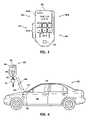
- FIG. 1illustrates such a prior art fob 20 that includes, but is not limited to, “unlock” function button 22 , “lock” function button 24 , “alarm” function button 26 and key attachment aperture 27 in fob case 28 .
- FIG. 2illustrates fob 20 interacting with vehicle 40 . Key 30 is conveniently attached to fob 20 via attachment aperture 27 .
- fob 20sends wireless command signal 29 to nearby vehicle 40 where it is received by antenna 42 coupled to vehicle control system 44 .
- Control system 44interprets command signal 29 received from fob 20 and, depending upon which of functions 22 , 24 , 26 has been activated by the user, causes the corresponding vehicle sub-system to respond.
- control system 44causes lock 46 on door 48 to move from a locked to an unlocked position.
- the prior art systemsare not limited to merely the unlock, lock and alarm functions illustrated in FIGS. 1-2 , but may perform other functions as well (e.g., engine start, lights ON/OFF, open trunk, etc.). Nevertheless, there continues to be a need for additional functions and other improvements for remote control systems, especially for vehicles applications.
- a portable control deviceis provided in accordance with an exemplary embodiment of the present invention that is configured to provide an operator with control of an operation of a vehicle.
- the portable control devicecomprise an input configured to receive an action of the operator that is indicative of the operation to be performed by the vehicle and a transmitter that is configured to send a first signal at least partly via a wireless connection with the vehicle that at least partially embodies a command for the action of the operator received by the input.
- the portable control devicecomprises a receiver configured to receive a second signal at least partly via the wireless connection with the vehicle that at least partially embodies feedback from a sensor of the vehicle indicative of the operation resulting from the command at least partially embodied by the first signal sent by the transmitter.
- the portable control devicecomprises an output configured to present information to the operator on the operation based at least in part on the feedback in the second signal received by the receiver.
- a systemwhich includes a control device, is provided in accordance with an exemplary embodiment of the present invention that is configured to provide an operator with control of an operation of a vehicle.
- the control devicecomprises an input configured to receive an action of the operator that is indicative of the operation to be performed by the vehicle, a first transmitter configured to send a first signal that at least partially embodies a command for the action of the operator received by the input, and a first receiver configured to receive a second signal that at least partially embodies feedback indicative of the operation resulting from the command at least partially embodied by the first signal sent by the first transmitter.
- the control devicealso comprises an output configured to present information to the operator based at least in part on the feedback in the second signal received by the receiver.
- the systemalso comprises an electronic control system substantially affixed to the vehicle that is configured for connection to the control device via an at least partly wireless connection.
- the electronic control systemcomprises a second receiver configured to receive the first signal from the first transmitter via the at least partly wireless connection, a controller configured to receive the command in the first signal sent by the first transmitter and further configured to generate a third signal that controls the operation of the vehicle.
- the electronic control systemcomprises a sensor configured to generate the feedback indicative of the operation resulting from the third signal generated by the controller and a second transmitter configured to send the second signal with the feedback to the first receiver via the at least partly wireless connection.
- a methodfor operating a portable control device, which is configured to provide an operator with control of an operation of a vehicle, in accordance with an exemplary embodiment of the present invention.
- the methodcomprises sensing an input provided to the portable control device by the operator that is indicative of the operation to be performed by the vehicle and transmitting a first signal to the vehicle via an at least partly wireless connection that at least partially embodies a command for the operation to be performed by the vehicle.
- the methodcomprises receiving a second signal from the vehicle via the at least partly wireless connection that at least partially embodies feedback from the vehicle indicative of the operation and generating an output that presents information to the operator on the operation based at least in part on the feedback.
- FIG. 1is a simplified plan view of a vehicle fob according to the prior art
- FIG. 2illustrates the fob of FIG. 1 interacting with a vehicle according to the prior art
- FIG. 3is a simplified plan view of a vehicle control device, which can also be referred to as a fob, according to an exemplary embodiment of the present invention
- FIG. 4illustrates the fob of FIG. 3 interacting with a vehicle according to an exemplary embodiment of the present invention
- FIGS. 5-8are simplified plan views of the vehicle control device in accordance with other exemplary embodiments of the present invention.
- FIG. 9is a simplified electrical schematic block diagram of the vehicle control devices of FIGS. 3-8 according to an exemplary embodiment of the present invention.
- FIG. 10is a simplified electrical schematic block diagram of a vehicle electronics system according to an exemplary embodiment of the present invention.
- FIG. 11is a schematic diagram of the vehicle electronics system of FIG. 10 according to another exemplary embodiment of the present invention.
- FIG. 12is simplified functional block diagram of yet another exemplary embodiment of the present invention.
- FIG. 13is a simplified flow chart of a method according to a further exemplary embodiment of the present invention.
- FIG. 14is a simplified flow chart of a method according to yet another exemplary embodiment of the present invention.
- FIG. 15is a simplified flow chart of a method according to still another exemplary embodiment of the present invention.
- FIG. 3is a simplified plan view of a vehicle control device 60 , which shall also be referred to herein as a fob, in accordance with an exemplary embodiment of the present invention.
- a vehicle control device or fobis intended to include remote control serving any number of purposes.
- the fobcan also act as a key-ring, cell phone, and/or portable computer.
- reference number 60 Ais used to refer particularly to fob 60 of FIG. 3 and reference number 60 B is used to refer particularly to fob 60 of FIG. 5 .
- reference number 60 Cis used to refer to fob 60 of FIG. 6 .
- reference number 60 Dis used to refer to fob 60 of FIG. 7 and reference number 60 E is used to refer to fob 60 of FIG. 8 .
- FIG. 4illustrates fob 60 interacting with vehicle 80 .
- Fob 60includes, but is not limited to, various command function buttons, switches, microphones, and/or other actuators 62 .
- fob 60includes, but is not limited to, function status display or audio annunciator 64 , and optional aperture 65 in fob body 66 for object attachment, such as attachment of one or more keys 30 .
- reference number 62is used to generally refer to the input elements of fob 60 .
- reference numbers 62 A- 62 Eare used to generally refer to the particular input elements illustrated in FIGS. 3-8 , respectively.
- reference number 64is used to generally refer to the output display(s) and/or annunciator(s) of fob 60 and reference numbers 64 A- 64 E are used to generally refer to the arrangements particularly illustrated in FIGS. 3-8 , respectively.
- display or annunciator 64 Ais a Liquid Crystal Display (LCD), and in this example an LCD alphanumeric display, although other configurations and devices can be utilized in accordance with the present invention.
- LCDLiquid Crystal Display
- display and LCDare intended to include other alternatives for presenting visual information. Accordingly, any type of visually perceivable display may be used for display 64 A.
- display 64 Acan be used as an input device for selection and activation by the user.
- Function buttons, switches or actuators 62 A of fob 60 Aare numbered 1-6 with a seventh button, switch or actuator identified as SEND. However, these identifications are merely for convenience of explanation and are not intended to be limiting.
- the numbers 1-6 and SENDcan be replaced by symbols that will assist the user with recognition of the function commanded by a particular button, switch or actuator.
- the use of a separate SEND button or switch to initiate transmission of a fob command to vehicle 80is not essential, since transmission may be arranged to occur directly upon actuating the desired command button or switch itself.
- the exact nature of the symbol or marking on a particular button, switch or actuatoris not critical to the exemplary embodiments of the present invention. Further, more or fewer than seven function buttons, switches or actuators may be included in fob 60 .
- a microphonecan also be included to provide for voice activation.
- the words “input”, “button”, “switch” and “actuator” with reference to fob 60are used interchangeably to indicate any convenient means of selecting and/or initiating a command signal from fob 60 .
- actuators 62may be pressure actuated switches, optical sensors, or capacitive sensors that detect the presence or absence of a finger or stylus touching or approaching the actuators, magnetic switches, a voice activated microphone, and so forth.
- the exemplary embodiment of the present inventionis independent of the exact nature and means of operation of buttons, switches or actuators 62 , and all possible means of selecting and/or initiating a command signal from fob 60 are intended to be included in the exemplary embodiments of the present invention.
- Activating one or more of switches or other input means 62causes fob 60 to send wireless signal 68 to vehicle 80 where it is received by antenna 82 , which is coupled to Vehicle Electronics System (VES) 84 as shown in FIG. 4 .
- vehicle electronics system 84executes the command received via signal 68 and sends various response signals 83 back to fob 60 .
- the various response signals 83 sent back to the fob 60can be an intermediate status and/or execute completion signals that are then displayed or announced in whole or in part via status display 64 of fob 60 A.
- the user of fob 60 Aknows by means of the information presented on status display or annunciator 64 A, or equivalent annunciators illustrated in FIGS. 5-8 , that the function command issued using fob 60 A has been carried out.
- any intermediate execution values or other feedback information concerning the particular function being requested using fob 60 Acan also be presented on annunciator or display 64 A.
- FIGS. 5-8are simplified plan views of vehicle remote control and feedback fobs 60 according to further exemplary embodiments of the present invention. More particularly, fob 60 B is shown in FIG. 5 , fob 60 C is shown in FIG. 6 , fob 60 D is shown in FIG. 7 , and fob 60 E is shown in FIG. 8 . Generally, fobs 60 A, 60 B, 60 C, 60 D, 60 E differ in the manner in which the desired commands to be sent to vehicle electronics system 84 are entered into fob 60 and/or the manner in which the information in feedback signals 83 is presented to the user.
- fob 60 B of FIG. 5has various indicator lights 67 instead of LCD status display 64 A that can be a single color or multiple colors. One or more of lights 67 could also be shared by the various switches.
- depressing switch 62 - 2directs an engine start and corresponding command signal 68 is sent to vehicle system 84 , then after vehicle electronics system 84 has started the engine, it sends successful completion feedback via signal 83 to fob 60 B.
- Reception of successful completion feedback via signal 83 by fob 60 Bpreferably causes a light, such as a Light Emitting Diode (LED) 67 - 2 , to illuminate in a first mode (e.g., first color) to indicate that the command was successfully carried out.
- a lightsuch as a Light Emitting Diode (LED) 67 - 2
- system 84sends an unsuccessful completion feedback via signal 83 back to fob 60 B, and a light, such as light 67 - 2 , illuminates in another mode (e.g., illuminates in a color other than the first color) or otherwise indicates that the desired function was not completed successfully. In this manner, the results of any particular function command can be communicated back to the user.
- a lightsuch as light 67 - 2 , illuminates in another mode (e.g., illuminates in a color other than the first color) or otherwise indicates that the desired function was not completed successfully.
- Fob 60 Billustrates a further variation in accordance with an exemplary embodiment of the present invention, in which buttons or switches 62 B numbered 1-6 are push or touch type switches and switch numbered 7-8 is a rocker type switch, indicating that fob 60 may include any type of actuator switch. While lights 67 are shown in FIG. 5 as being separate from switches 62 B, the lights 67 may be interior to or incorporated within switches 62 B. This is particularly convenient where switches 62 are labeled with symbols indicative of the function and assists in viewing in a reduced light environment.
- Fob 60 C of FIG. 6illustrates alternate feedback displays or annunciators that are provided in accordance with an exemplary embodiment of the present invention. More specifically, fob 60 C includes speaker or annunciator 70 adapted to provide audible feedback to the user based on feedback signals 83 received from vehicle 80 . For example, assuming that push-button 62 - 2 causes fob 60 to transmit an engine start command, then when feedback signal 83 is received from vehicle 80 as shown in FIG. 4 , audio speaker 70 will announce “engine start successful” or “engine start unsuccessful,” as the case may be.
- vehicle electronics system 84may send back the current inside temperature, outside temperature, whether rain is detected by the vehicle rain sensor, whether the air conditioning system is running, and so forth, which result can be announced via speaker 70 .
- the various messages and announcements to be provided by speaker 70are preferably pre-determinable and hence can be conveniently, but not essentially, stored in a memory of the fob 60 .
- feedback signal 83need not actually contain the message itself, but only an address or point to an appropriate message that can be retrieved from memory and then audibly played, visually displayed, or both.
- Fob 60 C of FIG. 6illustrates a further variation of an exemplary embodiment of the present invention that utilizes light bar 69 .
- light bar 69is a row of LEDs or other emitters that progressively illuminate in response to particular feedback signals from vehicle 80 .
- light bar 69indicates that the inside vehicle temperature is about 70 Fahrenheit (° F.) on a scale of 60-80° F. as shown by legend 71 .
- fob 60 Cis also provided with variable control 72 having movable slider 73 so that the user can input different values of a desired variable in an analog like fashion.
- depressing switch 62 - 8can cause fob 60 C to enter a “select temperature value” mode.
- at least switch 62 - 8have an interior light so that it flashes when in this mode as shown in FIG. 6 .
- moving slider 73is configured to cause light bar 69 to progressively illuminate to indicate a desired vehicle interior temperature.
- a second activation of button 62 - 8turns off the flashing mode of switch button 62 - 8 and causes the selected temperature to be sent to vehicle 80 for execution via signal 68 .
- the foregoing exampleis intended to be illustrative of a possible additional mode of operation of the exemplary embodiment of the present invention and not intended to be limiting.
- Fob 60 D of FIG. 7illustrates a further variation of fob 60 of an exemplary embodiment of the present invention.
- display 64 Dfacilitates command function selection as well as displaying the results of command execution by vehicle electronics system 84 .
- Switch 74 , 74 ′is provided with each angular position of switch 74 , 74 ′ corresponding to a particular function that can be commanded on vehicle 80 .
- a list of available function commandsis conveniently presented on display 64 .
- Rotating pointer 74 P of switch 74 , 74 ′ to any particular function position 75causes the function to be highlighted on display 64 D.
- user rotation of rotating switch 74 , 74 ′can be used to scan through the available command functions and select that which is desired by, for example, pressing SEND.
- the SEND functioncould also be incorporated as part of the dial wheel 74 , 74 ′.
- Rotating switch or dial-wheel 74 , 74 ′may be mounted on the face of fob case 66 as shown by reference number 74 or protrude through the side of case 66 as shown by reference number 74 ′.
- Fob 60 E of FIG. 8illustrates a further variation of fob 60 of the exemplary embodiment of the present invention.
- input 62 Eincludes microphone 76 for receiving spoken commands (i.e., voice activation of fob 60 E).
- pressing switch 77energizes microphone 76 .
- display 64 E of fob 60 Ecan be used to list the available commands, allowing the user to select the desired command by voice activation.
- Other switchescan also be provided as illustrated in fob 60 E, but this is not essential.
- Display 64 Ealso presents the feedback received from vehicle electronics system 84 so that the user may confirm execution or failure of the command sent to vehicle 80 .
- fobs 60 A. 60 B, 60 C, 60 D, 60 E in FIGS. 3-8have been illustrated as having particular combinations of function selections means or parameter selection means (e.g., buttons, switches, sliders, dial-wheels, microphones, etc.) and various feedback means (e.g., alphanumeric display, signal lights, light bars, audio output, etc.), the present invention is not limited to merely one combination or the other as implicitly or explicitly referred to in this detailed description. Rather, any combination of input and output elements may be used in the fob of the exemplary embodiment of the present invention according to the needs of the system designer and user.
- function selections means or parameter selection meanse.g., buttons, switches, sliders, dial-wheels, microphones, etc.
- various feedback meanse.g., alphanumeric display, signal lights, light bars, audio output, etc.
- an audio speaker and an alphanumeric displaymay be used in the same fob
- a light-bar like display elementmay be included in the alphanumeric display or separately
- some switch actuatorsmay illuminate and others not
- sliders or rotating knobs or dial-wheels or volume or analog controlsmay be incorporated in the main faces and/or on the sides of case 66 as needed, and so forth. It is intended that all such combinations and variations be included in the exemplary embodiment of the present invention.
- antenna or antennas that transmit and receive wireless signals 68 , 83 from and to fobs 60are omitted in FIGS. 3-8 .
- the particular types of antennaswill depend upon the signaling frequencies and protocols chosen by the designer and user. Suitable antennas are well known in the art and are shown schematically in FIGS. 9-11 .
- FIG. 9is a simplified electrical schematic block diagram of electronic system 90 of fob 60 of FIGS. 3-8 according to an exemplary embodiment.
- Fob electronics system 90includes, but is not limited to, input 91 (e.g., switches 62 , slider 73 , rotary selection knob 74 , 74 ′, microphone 76 , etc.), signal processor or controller 92 , memory 93 , transceiver 94 (i.e., transmitter/receiver) with antenna 95 , annunciator 96 (e.g., displays and/or lights 64 , 67 , 69 , speaker 70 , etc.) and battery or other energy storage means 98 .
- Input 91is coupled to processor 92 via bus or leads 86 .
- Processor 92is coupled to memory 93 by bus or leads 85 and to transceiver 94 and annunciator 96 by bus or leads 87 .
- Annunciator 96may include, but is not limited to, any of the various forms of output elements and input 91 may include any of the various input elements discussed in connection with fobs 60 of FIGS. 3-8 .
- Poweris supplied to the various elements by DC power leads 88 , 88 ′.
- Battery switch 99is desirable, but not essential, to permit battery 98 to be disconnected when fob 60 is not in use. Battery switch 99 may be incorporated into input 91 so that when any switch or other element 62 in input 91 is activated, switch 91 closes and supplies power to the various elements of fob electronics system 90 .
- a time-out circuit(not shown) is desirably included, so that switch 99 opens automatically after a predetermined period of non-use.
- processor 92when the user activates a particular selection (e.g., switch 62 , 73 , 74 , 74 ′, 76 , voice commands, etc.) of input 91 corresponding to a predetermined vehicle action or function to be carried out (e.g., door(s) lock/unlock; engine start/stop; window(s) up/down; trunk open/close; environmental control on/off; temperature up/down; lights on/off; rain detect on/off, wipers on/off, alarm arm/disarm; alarm on/off, top down/up, and so forth), processor 92 generates the corresponding function command, which it passes to transceiver 94 .
- a predetermined vehicle action or functione.g., door(s) lock/unlock; engine start/stop; window(s) up/down; trunk open/close; environmental control on/off; temperature up/down; lights on/off; rain detect on/off, wipers on/off, alarm arm/disarm; alarm on/off
- Transceiver 94generates modulated wireless signal 68 for transmission to vehicle electronics system 84 via antennas 95 , 82 .
- the command transmitted via wireless signal 68is conveniently in coded form to minimize the signal duration and power.
- Any suitable signaling method and protocolmay be used such as Bluetooth®, 802.11, WiFi, Zigbee, and so forth. However, transmission by modulated RF signals is preferable.
- FIG. 10is a simplified electrical schematic block diagram of vehicle electronics system (VES) 84 with which fob 60 communicates via vehicle antenna 82 .
- System 84includes, but is not limited to transceiver 100 , controller 102 , memory 104 , sensors 106 , actuators 108 and optional other input 110 .
- Antenna 82is coupled to transceiver 100 , which is in turn coupled to controller 102 via bus or leads 101 .
- Controller 102is coupled to memory 104 via bus or leads 103 , to sensors 106 via bus or leads 105 , to actuators 108 via bus or leads 107 and to optional other input/output (I/O) 110 via bus or leads 109 .
- I/Oinput/output
- bus or leads 101 , 103 , 105 , 107 , 109are illustrated as coupling the various elements of VES 84 individually to controller 102 , this is merely for convenience of description and not intended to be limiting. Some or all of elements 100 , 102 , 104 , 106 , 108 , 110 can be coupled via a common bus.
- VES 84may be self contained, that is, including both actuators 108 and sensors 106 needed to execute various commands received from fob 60 or alternatively act as a transfer agent for interpreting and forwarding fob commands to various Electronic Control Units (ECUs) elsewhere in the vehicle.
- ECUsElectronic Control Units
- controller 102is conveniently interfaced to other vehicle electronic control units as per vehicle architecture via bus or leads 111 . Either arrangement or a combination thereof is useful and numerous means can be utilized to accomplish such interconnection.
- Transceiver 100demodulates signal 68 received from fob 60 and passes the command contained in the signal 68 to controller 102 .
- Controller 102may also receive input commands via other I/O 110 .
- Controller 102interprets the received command according to data and instructions stored in memory 103 and energizes the appropriate actuators 108 to carry out the command or passes the command to another ECU via bus or leads 111 .
- Controller 102also interrogates sensors 106 to monitor progress of execution of the command received from fob 60 and to determine the completion state or, alternatively, obtains such data from other ECUs via bus or leads 111 , depending on the mode of operation.
- controller 102when the command corresponds to an engine start, then controller 102 causes the engine start sequence stored in memory 104 to be performed and monitors, among other things, the engine Rotations Per Minute (RPM) sensor or a flag set by the RPM sensor to determine whether the engine start was successful.
- RPMRotations Per Minute
- controller 102causes the results to be reported back to the command source.
- controller 102passes the engine start command to an ECU responsible for power train control, which issues the necessary local instructions to start the engine and passes the results back to controller 102 .
- the feedback responseis sent via signal 83 from transceiver 100 and antenna 82 of vehicle electronics system 84 to fob 60 where it is received by antenna 95 and transceiver 94 .
- Transceiver 94demodulates received signal 83 and passes the response contained in the signal to fob processor 92 , which causes fob annunciator 96 to display the appropriate response or generate a sound corresponding to the appropriate response, or a combination of the two.
- feedback signal 83is a coded response, such as a memory address or equivalent, that fob processor 92 uses to retrieve the corresponding message to be displayed or announced by annunciator 96 from memory 93 .
- a similar arrangementis used for signals 68 flowing from fob 60 to vehicle 80 . This arrangement simplifies the wireless signal being exchanged between fob 60 and vehicle 80 .
- the command signalwas received via other Input/Output (I/O) 110 , then the resulting feedback signal is sent back via other I/O 110 as subsequently explained in greater detail in connection with FIG. 12 .
- I/OInput/Output
- the end result of the signal exchange between fob 60 or other remote as shown in FIG. 12 , and vehicle 80is that the fob user can determine by reference to the fob itself or other remote whether or not the requested command was properly executed and/or the desired vehicle status.
- FIG. 11is a schematic diagram of vehicle electronics system (VES) 84 ′ analogous to VES 84 of FIG. 10 in accordance with another exemplary embodiment.
- VESvehicle electronics system
- fob 60 ′is shown as employing two antennas 95 .
- Antenna 95 Tis provided for transmitting signal 68 and antenna 95 R is provided for receiving signal 83 , but this is merely for convenience of illustrating a further variation of the exemplary embodiment of the present invention and not intended to be limiting.
- Vehicle electronics system 84 ′is also illustrated as employing separate receive antenna 82 R and transmit antenna 82 T instead of combined antenna 82 of FIG. 10 .
- a single antenna serving a single transceivermay be used or separate antennas serving the receiver and transmitter or a combination thereof may also be used in accordance with the present invention.
- Vehicle electronics system (VES) 84 ′comprises fob interface module 120 and vehicle control system 160 that intercommunicate via vehicle data communications bus (VDCB) 140 .
- Vehicle control system 160includes, but is not limited to, various subsidiary electronic control units (ECUs).
- vehicle control system 160can include engine management control unit 162 , environmental control unit 164 , body electronics control unit 166 and other ECUs 168 .
- Fob interface module 120includes, but is not limited to, receiver 121 coupled to antenna 82 R for receiving fob signal 68 , and transmitter 122 coupled to antenna 82 T for transmitting vehicle wireless feedback signal 83 to fob 60 .
- Receiver 121 and transmitter 122are coupled via bus or leads 123 to processor 124 .
- Other I/O 110is coupled to processor 124 via leads or bus 109 and provides a pathway for commands originating from other sources other than fob 60 .
- Processor 124interprets the demodulated commands from receiver 121 or other I/O 110 and generates the appropriate responses to be returned via transmitter 122 or other I/O 110 .
- Processor 124is coupled via bus or leads 125 to memory 126 that is configured to store information such as execution routines, code tables and data.
- Portion 126 - 1is referred to as the VALID COMMANDS MEMORY that is preferably utilized to store the identity of fobs whose commands can be executed and those commands that a particular fob 60 is permitted to execute. This prevents fobs from another vehicle improperly addressing controller 84 , 84 ′ or even the fob for vehicle 80 from commanding undesired or prohibited command actions.
- Portion 126 - 2is referred to as the EXECUTE & REPORT SEQUENCE MEMORY, which is conveniently used to store the subroutines for executing a particular command and/or determining whether any intermediate sensor values should be reported back to fob 60 .
- an environmental command that would involve energizing the air conditioning systemgenerally has an engine start as a prerequisite to powering-up the climate control compressor.
- the execute sequence for such an environmental commandcould include, for example: (i) start engine, (ii) set fast idle, (iii) turn-on A/C compressor, (iii) turn on blower, (iv) set temperature control point, (v) measure interior temperature every X minutes, (vi) report intermediate temperature values to fob, . . . (n) report reaching temperature end point.
- Processor 124is coupled to bus interface unit 128 via bus or leads 127 , which is in turn coupled to VDCB 140 via leads or bus 129 .
- Processor 124causes the commands received from fob 60 to be executed by communicating with other vehicle subsystems (e.g., ECUs 162 , 164 , 166 , 168 , etc.) via bus interface unit 128 and VDCB 140 .
- vehicle subsystemse.g., ECUs 162 , 164 , 166 , 168 , etc.
- processor 124is shown as being directly coupled to other elements of fob interface module 120 by various leads or buses 109 , 123 , 125 , 127 , this is merely for convenience of explanation and not intended to be limiting. Such elements can be coupled to each other and to bus interface 128 via a common or shared bus or leads.
- Vehicle control module 160conveniently comprises various vehicle ECUs.
- engine management control unit 162environmental control unit 164 , body electronics control unit 166 , other control units 168 and global sensors 170 , are coupled by local busses or leads 163 - 171 to VCDB 140 and thereby to each other and fob interface module 120 .
- Each ECUis preferably coupled by a local bus or leads to actuators and/or local sensors appropriate to its function.
- engine management control unit 162is coupled to engine management actuators/sensors 162 A/S via bus or leads 173
- environmental control unit 164is coupled to environmental actuators/sensors 164 A/S via bus or leads 175
- body electronics control unit 166is coupled to body electronics actuators/sensors 166 A/S via bus or leads 177
- other control units 168are coupled to their corresponding actuators/sensors 168 A/S by bus or leads 179 . While this particular arrangement of individual ECUs and their respective actuators and local sensors is convenient, it is not essential and any arrangement that allows signals to be passed from and to fob interface module 120 and the appropriate controllers, actuators and sensors may be used in accordance with the present invention.
- Global sensors 170 coupled to VDCB 140 via bus or leads 171are generally those sensors whose output is used by multiple ECUs, although this is not essential.
- the sensor status outputs that are to be fed back to fob 60are preferably available on VDCB 140 by either bus 171 or from local sensors 162 A/S, 164 A/S, 166 A/S, 168 A/S via their respective ECUs 162 , 164 , 166 , 168 and coupling buses 163 , 165 , 167 , 169 .
- system 84 ′ of FIG. 11shows memory 126 as being apart of fob interface module 120 and coupled directly to processor 124 , this is merely convenient and not essential. Memory 126 could be, for example, coupled to processor 124 via VDCB 140 and/or be part of processor 124 and/or be shared with other vehicle sub-systems.
- a command from fob 60 or via other I/O 110is received and decoded in fob interface module 120 .
- the corresponding execute/report sequenceis preferably retrieved from memory 126 and sent via bus interface 128 and VDCB 140 to the appropriate controller(s) (e.g., one or more of ECUs 162 , 164 , 166 , 168 ) in vehicle control system 160 .
- the appropriate controller(s)executes the desired command and provides the appropriate sensor or status output on VDCB 140 to be retrieved by interface module 120 , which is reported back to fob 60 by wireless signal 83 or to an alternate command originator via other I/O 110 .
- FIG. 12is a simplified functional block diagram of system 180 according to a further exemplary embodiment of the present invention adapted to be useable at longer distances and according to several variations.
- Portion 181 of system 180is generally contained within vehicle 80 and the remainder is generally external to vehicle 80 .
- Portion 181contains vehicle electronics system (VES) unit 191 , which is analogous to VES units 84 , 84 ′, interface unit 190 , optional vehicle cell phone 189 , and optional electronic control unit (ECU) or equivalent 197 .
- VESvehicle electronics system
- ECUelectronice control unit
- cell phone 189is coupled to VES 191 via interface unit 190 and/or ECU 197 is coupled directly to VES 191 .
- ECU 197preferably has a built-in cell phone that interfaces to the vehicle bus that is part of VES 191 , which is analogous to bus 140 of VES 84 ′ shown in FIG. 11 .
- System 180uses cell phone 184 and/or personal computer (PC) or personal digital assistant (PDA) 192 as remote control devices to control operation of vehicle 80 at much larger distances than would be possible with fob 60 .
- Cell phone 184 and PC/PDA 192serve the same function as fob 60 as far as originating commands and receiving and displaying or announcing the command results fed back from vehicle 80 , and are capable of the full range of control functions already described in connection with fob 60 .
- first branch 182 of system 180utilizing cell phone 184 and its associated network for the entire communication link to vehicle 80 .
- the useractivates cell phone 184 in the usual manner and places a call via cell network 187 to vehicle cell phone 189 or via network 185 , 196 to the cell phone embedded in ECU 197 .
- Vehicle cell phone 189 or ECU 197is programmed to answer and, for example, return a tone indicating that it is ready to receive commands.
- the usermay send a tone after cell phone 189 or ECU 197 has answered, telling cell phone 189 or ECU 197 and VES 191 that transmission of vehicle action commands are about to begin.
- the userconveniently issues commands to VES 191 via vehicle cell phone 189 and interface unit 190 or via ECU 197 by, for example, depressing a particular combination of keys or speaking a particular voice command into cell phone 184 .
- the usercan activate cell phone 184 and execute an embedded software application in the cell phone. This alternative allows the user to select the desire remote functions and send the selected command.
- cell phone 184will utilize the standard wireless mobile internet interface and send the command, for example, via TCP/IP to cell phone 189 or the cell phone embedded in ECU 197 .
- processor 92 , 124 as shown in FIGS. 10-11 of VES unit 191receives the commands via other I/O 110 and interprets and executes them in generally the same way as if received from fob 60 .
- Command status feedbackis returned to cell phone 184 over the same network path as the incoming commands, and cell phone 184 is conveniently programmed to display the results on its built-in display 184 D.
- VES 191can send back an audio message stating the results to be played by cell phone 184 , just as described in the case of fob 60 C. In either case, the user can send the desired command and receive visual feedback, audible feedback, or a combination of visual and audible feedback of the result.
- PC/PDA 192is used for the input function.
- PC/PDA 192is in radio communication via link 192 - 1 with Wi-Fi network 194 , which in turn is coupled to internet 195 , or is in wireline communication via link 192 - 2 with internet 195 .
- data transmissions originating in PC/PDA 192are routed via internet 195 to cell network 187 and/or network 196 .
- PC/PDA 192dials vehicle cell phone 189 or ECU 197 , which are coupled via wireless links 187 - 1 and 196 - 1 , respectively, with cell network 187 and network 196 .
- PC/PDA 192 and cell phone 184may also be used to alter data (e.g., execution sequences, reporting parameters and frequency, allowed commands, etc.) stored in VES 191 , as for example, in memory 104 , 126 as shown in FIGS. 10-11 .
- datae.g., execution sequences, reporting parameters and frequency, allowed commands, etc.
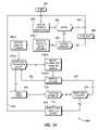
- FIG. 13is a simplified flow chart of method 200 of the exemplary embodiment of the present invention according to a first exemplary embodiment and FIG. 14 is a further flow chart of method 200 designated as method 200 ′ showing greater detail and additional features.
- the labels “NO” and “YES” on the figurescorrespond to logical NO or FALSE and logical YES or TRUE, respectively, to queries in these methods.
- the same reference numbersare used in FIGS. 13-14 to indicate steps common to both methods 200 and 200 ′ and suffixes (e.g., 210 - 1 , 210 - 2 , etc.) are used to indicate that a step has been divided into various sub-steps and additional features.
- method 200begins with START 202 and initial step 204 when a command is received by vehicle electronics system 84 , 84 ′ via wireless signal 68 from fob 60 or by VES 191 from remote 184 , 192 .
- Vehicle electronics system 84 , 84 ′, 191then executes queries 206 , 208 in either order.
- queries 206it is determined (e.g., by reference to data stored in memory 104 , 126 ) whether or not the particular fob or remote is authorized to send commands to this vehicle and whether the command received is among those authorized to be executed.
- method 200loops back to start 202 and initial step 204 . If the outcome of query 206 is YES (i.e., TRUE), indicating that both the fob or remote and the command are valid, then method 200 proceeds to ALREADY RUNNING ? query 208 where it is determined whether a command is already underway. This can occur, for example, if the user presses the same or another command button or function without waiting for execution of the first command to complete.
- method 200proceeds to optional SEND BUSY step 209 , wherein fob 60 or remote 184 , 192 provides notification that an incomplete command is already running, and then, as shown by path 207 , and method 200 loops back to start 202 and initial step 204 . If the outcome of query 208 is NO (i.e., FALSE), indicating that a command is not already running, then method 200 proceeds to EXECUTE COMMAND step 210 where the execute sequence that is retrieved from memory 104 , 126 is passed to the appropriate controller for execution.
- NOi.e., FALSE
- SENSE STATE step 212is executed with a query of the appropriate sensor or status log (e.g., identified from memory 104 , 126 ) to determine the current state of the system or subsystem being addressed.
- the reported stateis compared with the commanded state to determine whether or not the commanded state has been achieved. If the outcome of query 214 is NO (i.e., FALSE), which indicates that the desired end state has not yet been achieved, method 200 proceeds via optional RETRY LIMIT REACHED ? query step 216 where a determination is made as to whether a predetermined re-try limit has been reached. If the outcome of query 216 is NO (FALSE) then, as shown by path 217 , method 200 loops back to execute command step 210 wherein execution continues.
- FALSERETRY LIMIT REACHED ? query
- Method 200repeats steps 210 , 212 , 214 , 216 until either step 214 or step 216 yields YES (i.e., TRUE). Either the commanded state has been achieved or the commanded state has not been achieved, but the re-try limit has been reached (YES (i.e., TRUE) to 216 ), whereupon method 200 proceeds to REPORT RESULT TO REMOTE step 218 .
- YESi.e., TRUE
- step 218the outcome of SENSE STATE step 212 is sent back to fob 60 via signal 83 or to remote 84 , 192 via paths 182 , 183 , reporting either success (YES (i.e., TRUE) to 214 ) or failure (YES (i.e., TRUE) to 216 ) as the case may be.
- method 200returns to START 202 and first step 204 as indicated by path 219 .
- step 210 - 1is executed with an execute and report sequence corresponding to the command received from fob 60 or remote 184 , 192 that is retrieved from memory 104 , 126 .
- step 210 - 2this execute sequence is initiated.
- query 210 - 3it is determined whether, according to the retrieved sequence, there are intermediate values of sensed or measured or stored variables that are to be reported, as for example a current temperature reading before or after turning on the air conditioning system in the vehicle, or the engine temperature before or after an engine start, or whatever sensor or status output is built into the execute/report sequence retrieved from memory. If the outcome of query 210 - 3 is YES (i.e., TRUE), then method 200 ′ proceeds to step 210 - 4 where the intermediate state or appropriate sensor readings or stored values are reported to fob 60 via fob interface module 120 or remote 184 , 192 by VES 191 .
- YESi.e., TRUE
- method 200 ′proceeds to CONTINUE EXECUTE step 210 - 5 from which it returns via path 211 to query 210 - 3 .
- Method 200 ′repeats steps 210 - 3 , 210 - 4 , 210 - 5 until a NO (i.e., FALSE) outcome results from query 210 - 3 and it proceeds to SENSE STATE step 212 as before in method 200 .
- NOi.e., FALSE
- queries 214 , 216are executed and if both queries 214 , 216 result in NO (i.e., FALSE) outcomes, then method 200 ′ loops back to step 210 - 5 as shown by path 217 . If either of queries 214 , 216 yields a YES (i.e. TRUE) outcome, then method 200 ′ proceeds to REPORT RESULTS TO REMOTE step 218 (e.g., to fob 60 or cell phone 184 or PC/PDA 192 , etc.) and recycles back to START 202 via path 219 , the same as for method 200 .
- REPORT RESULTS TO REMOTE step 218e.g., to fob 60 or cell phone 184 or PC/PDA 192 , etc.
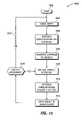
- FIG. 15is a simplified flow chart of method 300 of another exemplary embodiment of the present invention.
- Methods 200 , 200 ′ and 300differ in that methods 200 , 200 ′ concern operations performed primarily by vehicle electronics system 84 , 84 ′ while method 300 concerns operations performed primarily by fob 60 or remotes 184 , 192 .
- For convenience of illustration operation of method 300is described in terms of functions performed by circuit elements 90 of fob 60 . However, the elements capable of performing analogous functions are present in cell phone 184 and PC/PDA 192 .
- method 300begins with START 302 and initial step 304 in which input keystrokes or voice commands or other activations by the user are sensed, such as from input 91 operating in conjunction with processor 92 as shown in FIG. 9 .
- Processor 92uses the keystrokes, voice input or other activation received from input 91 and in step 306 retrieves from memory 93 the vehicle electronics system (VES) command(s) corresponding to those keystroke(s) or voice commands, etc.
- VESvehicle electronics system
- step 306processor 92 retrieves from memory 93 the code that will cause vehicle electronics system 84 , 84 ′ to carry out this action when button 62 - 2 is activated.
- this codeis transmitted to vehicle 80 by transceiver 94 via signal 68 where it is received by transceiver 100 or receiver 121 . Receipt of this command signal from fob 60 corresponds to step 204 in method 200 , 200 ′.
- transceiver 94 of fob 60receives signal response 83 from vehicle electronics system (VES) 84 , 84 ′ and demodulates signal 83 to obtain the response code sent by VES 84 , 84 ′.
- processor 92uses this response code to retrieve from memory 93 or otherwise calculate the annunciator code for the display and/or audio presentation that represents to the user the results corresponding to the result code obtained from VES 84 , 84 ′ of vehicle 80 (e.g., has the engine started).
- this informationis sent to annunciator 64 , 67 , 69 , 70 , etc., so as to be available to the user.
- Method 300then proceeds to optional query 316 where it is determined whether or not the result received from VES 84 , 84 ′ is an intermediate result or a final result. In other words, are further responses from VES 84 , 84 ′ expected in connection with the command originated by fob 60 . The information needed to make this determination is preferably included in the response code feedback by VES 84 , 84 ′. This is possible since the execute and report sequence retrieved in step 210 - 1 of method 200 ′, for example, can indicate whether multiple results are to be sent back to fob 60 . If the outcome of query 316 is YES (i.e., TRUE), then method 300 loops back to receive further vehicle response(s) in step 310 . Steps 310 - 314 are repeated until the outcome of query 316 is NO (i.e., FALSE), whereupon method 300 returns to start 302 and initial step 304 as shown by path 317 .
- NOi.e., FALSE
- methods 200 , 200 ′ and method 300are to be read together since they describe portions of a process for generating vehicle control commands in a portable controller (e.g., a fob, cell phone, PC/PDA or other remote control), at least partly wirelessly transmitting them from the controller to a vehicle spaced apart from the controller, and at least partly wirelessly feeding back interim (optional) and final command status information from the vehicle to the controller, where this information is displayed for the user audibly, visually or both.
- a portable controllere.g., a fob, cell phone, PC/PDA or other remote control
- method 300also applies equally well to cell phone 184 and/or PC/PDA 192 and the description of method 300 in terms of fob 60 is intended to also apply to the situation where the command originates from cell phone 184 or PC/PDA 192 .
- the system and method of the exemplary embodiment of the present inventionprovides the user of fob 60 or other remote device 184 , 192 in connection with vehicle electronics system 84 , 84 ′, and 191 considerable flexibility of operation.
- the usermay enter parameters (e.g., desired temperatures, light levels, etc.) into fob 60 or other remote device 184 , 192 and transmit these to vehicle 80 in connection with a command to perform a related function.
- the usermay, by means of such parameters and available commands, instruct vehicle 80 to report sensor readings of interest, e.g., outside temperature, inside temperature, rain, freezing conditions, engine speed, lock status, alarm status, and so forth.
- Use of dial-wheel 74 , 74 ′also conveniently provides a large number of choices, either alone or in conjunction with display 64 D, 64 E and/or annunciator 70 .
- a virtue of the exemplary embodiment of the present inventionis that display 64 D, 64 E and/or annunciator 70 of fob 60 or other remote device 184 , 192 can be used to display or present the command codes available to be selected and the switch combinations needed to select them.
- the userneed not remember the large number of available command codes, but can select the ones desired by referring to the display and/or annunciator and activating the switches or providing voice commands as directed thereon.
- a large number of functionscan be directed by the fob or other remote of the exemplary embodiment of the present invention without burdening the user with a remembering them all.
- the feedback and display and/or annunciator on fob 60 or other remote device 184 , 192informs the user as to the result of the command or inquiry transmitted by fob 60 or other remote device 184 , 192 to the vehicle.
- the exemplary embodiment of the present inventionapplies equally well to any type of portable signaling device capable of receiving user inputs, transmitting signals that are at least partly wirelessly communicated to the vehicle, receiving feedback transmitted at least partly wirelessly from the vehicle to the portable device, and displaying or announcing (or both) feedback results in a manner apparent to the user.
- the word “remote”is intended to include all such signaling devices and not be limited merely to fobs, PDAs, PCs, Cell Phones, etc., illustrated herein.
- an “annunciator”is intended in its broadest sense to include both visual and/or audible presentations of information.
- an “annunciator”may comprise one or more indicator lamps or other illuminating device(s), an alphanumeric display, a light bar, a loud speaker, a horn, a buzzer, a tactile vibrator or other sound or vibration making device, and any combination thereof.
Landscapes
- Engineering & Computer Science (AREA)
- Mechanical Engineering (AREA)
- Lock And Its Accessories (AREA)
Abstract
Description
Claims (4)
Priority Applications (2)
| Application Number | Priority Date | Filing Date | Title |
|---|---|---|---|
| US11/360,935US7504931B2 (en) | 2005-03-16 | 2006-02-23 | Remote feedback for vehicle key fob functions |
| DE102006011704ADE102006011704A1 (en) | 2005-03-16 | 2006-03-14 | Remote feedback for vehicle keyfob functions |
Applications Claiming Priority (2)
| Application Number | Priority Date | Filing Date | Title |
|---|---|---|---|
| US66240705P | 2005-03-16 | 2005-03-16 | |
| US11/360,935US7504931B2 (en) | 2005-03-16 | 2006-02-23 | Remote feedback for vehicle key fob functions |
Publications (2)
| Publication Number | Publication Date |
|---|---|
| US20060220806A1 US20060220806A1 (en) | 2006-10-05 |
| US7504931B2true US7504931B2 (en) | 2009-03-17 |
Family
ID=37055602
Family Applications (1)
| Application Number | Title | Priority Date | Filing Date |
|---|---|---|---|
| US11/360,935Expired - Fee RelatedUS7504931B2 (en) | 2005-03-16 | 2006-02-23 | Remote feedback for vehicle key fob functions |
Country Status (2)
| Country | Link |
|---|---|
| US (1) | US7504931B2 (en) |
| DE (1) | DE102006011704A1 (en) |
Cited By (34)
| Publication number | Priority date | Publication date | Assignee | Title |
|---|---|---|---|---|
| US20070247323A1 (en)* | 2006-03-22 | 2007-10-25 | Funai Electric Co., Ltd. | Remote controller |
| US20080104757A1 (en)* | 2006-09-14 | 2008-05-08 | Rawls-Meehan Martin B | Methods and systems of an adjustable bed |
| US20080255718A1 (en)* | 2007-04-10 | 2008-10-16 | Maurice Tuff | Vehicle monitor |
| US20090096575A1 (en)* | 2007-10-10 | 2009-04-16 | Tieman Craig A | Vehicle remote access and control apparatus and communications gateway |
| US20090096596A1 (en)* | 2007-10-10 | 2009-04-16 | Sultan Michel F | Apparatus for medium-range vehicle communications and control |
| US20090121660A1 (en)* | 2006-09-14 | 2009-05-14 | Rawls-Meehan Martin B | Controlling adjustable bed features with a hand-held remote control |
| US20090243791A1 (en)* | 2008-03-28 | 2009-10-01 | Partin Dale L | Mini fob with improved human machine interface |
| US20100039215A1 (en)* | 2008-08-18 | 2010-02-18 | Gm Global Technology Operations, Inc. | Valet keyfob system |
| US20100090528A1 (en)* | 2006-11-09 | 2010-04-15 | Mark Makwinski | Dc power outlets in fixed power distribution systems in or on wall installations |
| US20100090799A1 (en)* | 2007-03-21 | 2010-04-15 | Johnson Controls Technology Company | Communication system including a vehicle electronic key, electronic key for use in a communication system and method for communicating information from a vehicle to a portable telecommunication terminal |
| US20100106345A1 (en)* | 2008-10-28 | 2010-04-29 | Jung-Hyun Hwang | Vehicle control method and apparatus of telematics terminal |
| US20100169291A1 (en)* | 2008-12-30 | 2010-07-01 | International Business Machines Corporation | System and method for prompting an end user with a preferred sequence of commands which performs an activity in a least number of inputs |
| US20100308986A1 (en)* | 2009-06-09 | 2010-12-09 | Dobryden Allen D | System for Transmitting Data Between a Hybrid Electric Vehicle and a Remote Transceiver |
| US20110257817A1 (en)* | 2007-10-10 | 2011-10-20 | Delphi Technologies, Inc. | System and method for communicating with a vehicle |
| US8375488B2 (en) | 2006-09-14 | 2013-02-19 | Martin B. Rawls-Meehan | Adjustable bed frame |
| CN103136825A (en)* | 2011-11-24 | 2013-06-05 | 欧姆龙汽车电子株式会社 | Information communication system and vehicle portable device |
| CN103353996A (en)* | 2013-07-17 | 2013-10-16 | 南京物联传感技术有限公司 | Vehicle wireless control system and state information feedback method based on same |
| US20130321127A1 (en)* | 2012-05-31 | 2013-12-05 | Steven E. Wilder | Remote barrier operator command and status device and operation |
| US8633836B1 (en)* | 2009-01-16 | 2014-01-21 | Lavonnia Ball | Vehicle locator |
| US8760283B2 (en) | 2011-10-26 | 2014-06-24 | Honda Motor Co., Ltd. | Smart communication system and method for illuminating an indicator on a portable device |
| US8909357B2 (en) | 2007-09-14 | 2014-12-09 | Martin B Rawls-Meehan | System for tandem bed communication |
| US8926535B2 (en) | 2006-09-14 | 2015-01-06 | Martin B. Rawls-Meehan | Adjustable bed position control |
| US8930087B2 (en) | 2011-08-09 | 2015-01-06 | GM Global Technology Operations LLC | Systems and methods for interference reduction during keyless ignition authentication |
| US20150057840A1 (en)* | 2012-04-23 | 2015-02-26 | Denso Corporation | Vehicle-mounted control system and vehicle-mounted control device |
| TWI494235B (en)* | 2012-11-06 | 2015-08-01 | Glocomm Technology Co Ltd | Distance warning method by applying bluetooth system |
| US9284755B2 (en) | 2014-07-10 | 2016-03-15 | Ingenuity Automotive, LLC | System for remotely checking locked status of a vehicle |
| US9352680B2 (en)* | 2014-09-17 | 2016-05-31 | General Motors Llc | Vehicle remote start attempts messaging system and method |
| US9527478B2 (en) | 2013-03-14 | 2016-12-27 | Omega Patents, L.L.C. | Remote function control system for a vehicle having a data communications bus and related methods |
| US9666040B2 (en)* | 2010-01-29 | 2017-05-30 | Immersion Corporation | Keyless entry device for haptic communications |
| US9685073B2 (en) | 2014-01-09 | 2017-06-20 | Honda Motor Co., Ltd. | Systems and methods that enable selecting a range for two-way wireless communication between a key fob and a vehicle |
| US9889818B2 (en)* | 2015-10-30 | 2018-02-13 | Leauto Intelligent Technology (Beijing) Co. Ltd. | Information processing method and information processing system |
| US9981615B2 (en)* | 2013-03-14 | 2018-05-29 | Omega Patents, L.L.C. | Remote function control system for a vehicle having a data communications bus and related methods |
| US10064784B2 (en) | 2006-09-14 | 2018-09-04 | Martin B. Rawls-Meehan | System and method of an adjustable bed with a vibration motor |
| US10864137B2 (en) | 2006-09-14 | 2020-12-15 | Ascion, Llc | System and method of an adjustable bed with a vibration motor |
Families Citing this family (62)
| Publication number | Priority date | Publication date | Assignee | Title |
|---|---|---|---|---|
| FR2919837B1 (en)* | 2007-08-10 | 2010-01-15 | Renault Sas | METHOD FOR CONTROLLING A MULTIMEDIA SYSTEM ON VEHICLE, DEVICE FOR IMPLEMENTING SAID METHOD |
| CN101076815A (en)* | 2004-10-15 | 2007-11-21 | 皇家飞利浦电子股份有限公司 | Method of operating a rfid system |
| JP2006127307A (en)* | 2004-10-29 | 2006-05-18 | Nippon Dempa Kogyo Co Ltd | Vehicle state notification system, component device thereof, and notification method |
| US8299905B2 (en)* | 2005-02-10 | 2012-10-30 | Quentin King | System for applying tactile stimulation to the controller of unmanned vehicles |
| US20080136660A1 (en)* | 2006-10-23 | 2008-06-12 | Bailey John J | Remote Controller for Patterned Flashing Lights on a Vehicle |
| KR100801426B1 (en)* | 2006-11-01 | 2008-02-05 | 주식회사 현대오토넷 | Vehicle wiper control system |
| US7990255B2 (en)* | 2006-11-02 | 2011-08-02 | Audiovox Corporation | Range extending positive repeater |
| US7650864B2 (en)* | 2006-11-17 | 2010-01-26 | Magna Electronics Inc. | Remote starter for vehicle |
| US8294558B2 (en)* | 2006-12-04 | 2012-10-23 | Fujitsu Ten Limited | Starting control apparatus and tuner device |
| DE202007004973U1 (en)* | 2007-04-04 | 2008-08-07 | Beck, Wilfried | Remote control for consumers in a building electricity network |
| US9161195B1 (en) | 2007-04-30 | 2015-10-13 | Sucxess LLC | Method, apparatus and system for placing emergency calls from a vehicle |
| EP2170658A1 (en)* | 2007-07-18 | 2010-04-07 | Robert C. Eisenman | Combination car alarm and personal locator system |
| DE102007039206A1 (en) | 2007-08-20 | 2009-06-10 | Bayerische Motoren Werke Aktiengesellschaft | Controller for transmitting information signal and/or control signal during opening of rear flap of vehicle, has receiver unit outputting information depending on information signal that is transmitted after expiration of time interval |
| JP2009062688A (en)* | 2007-09-04 | 2009-03-26 | Tokai Rika Co Ltd | Communication system for vehicle |
| US20090064696A1 (en)* | 2007-09-11 | 2009-03-12 | Ford Global Technologies, Llc | Automotive climate system and method of controlling same |
| CN101903919A (en)* | 2007-11-01 | 2010-12-01 | 盖恩斯伯勒硬件工业有限公司 | Electronic access system |
| US9177430B2 (en)* | 2007-11-30 | 2015-11-03 | The Chamberlain Group, Inc. | Moveable barrier operator translation system and method |
| DE102007061088B4 (en)* | 2007-12-19 | 2017-08-17 | Airbus Operations Gmbh | Temperature monitoring of an aircraft |
| DE102008015772B3 (en)* | 2008-03-26 | 2009-04-16 | Audi Ag | Motor vehicle and key for a motor vehicle |
| DE102008026676A1 (en)* | 2008-06-04 | 2009-12-10 | Huf Hülsbeck & Fürst Gmbh & Co. Kg | Mobile identification transmitter of a security system |
| JP5138486B2 (en)* | 2008-07-10 | 2013-02-06 | 本田技研工業株式会社 | Device anti-theft device |
| AU2009202622B2 (en)* | 2008-07-10 | 2010-12-23 | Honda Motor Co., Ltd. | Antitheft system |
| US8209093B2 (en)* | 2008-08-28 | 2012-06-26 | Nissan North America, Inc. | Adaptive instruction system for a vehicle |
| US8387406B2 (en)* | 2008-09-12 | 2013-03-05 | GM Global Technology Operations LLC | Refrigerant system oil accumulation removal |
| US8570145B2 (en) | 2009-02-09 | 2013-10-29 | Jonson C. Au | Security system, modules and method of operation thereof |
| US20100201481A1 (en)* | 2009-02-09 | 2010-08-12 | Au Jonson Chung-Shun | Security System, Modules and Method of Operation Thereof |
| DE102009017048A1 (en) | 2009-04-09 | 2010-10-14 | Volkswagen Ag | Method and device for transmitting data of a vehicle to a mobile device and a correspondingly designed mobile device and vehicle |
| US8261872B2 (en)* | 2009-06-08 | 2012-09-11 | Clark Equipment Company | Work machine having modular ignition switch keypad with latching output |
| US20110063076A1 (en)* | 2009-08-28 | 2011-03-17 | Omron Automotive Electronics, Inc. | Apparatus for preventing unauthorized use of a vehicle |
| US9715665B2 (en)* | 2009-09-21 | 2017-07-25 | Ford Global Technologies, Llc | Methods and systems for monitoring the condition of vehicle components from a nomadic wireless device or computer |
| US20110071725A1 (en)* | 2009-09-23 | 2011-03-24 | Ford Global Technologies, Llc | Remotely interacting with a vehicle to perform servicing and engineering functions from a nomadic device or computer |
| US8346432B2 (en)* | 2009-09-23 | 2013-01-01 | Ford Global Technologies, Llc | System and method for remotely controlling vehicle components from a nomadic communication device or computer |
| US8558690B2 (en)* | 2009-10-01 | 2013-10-15 | Ford Global Technologies, Llc | Vehicle system passive notification using remote device |
| US8558678B2 (en)* | 2010-02-25 | 2013-10-15 | Ford Global Technologies, Llc | Method and systems for detecting an unauthorized use of a vehicle by an authorized driver |
| US8525657B2 (en) | 2010-02-25 | 2013-09-03 | Ford Global Technologies, Llc | Methods and systems for determining a tire pressure status |
| US8614622B2 (en)* | 2010-03-08 | 2013-12-24 | Ford Global Technologies, Llc | Method and system for enabling an authorized vehicle driveaway |
| US10075806B2 (en)* | 2010-03-19 | 2018-09-11 | Ford Global Technologies, Llc | Wireless vehicle tracking |
| US20120310445A1 (en) | 2011-06-02 | 2012-12-06 | Ford Global Technologies, Llc | Methods and Apparatus for Wireless Device Application Having Vehicle Interaction |
| US20120319829A1 (en)* | 2011-06-15 | 2012-12-20 | Stephanie Ann Machado | "david" |
| US20130186154A1 (en)* | 2011-11-22 | 2013-07-25 | Alfred M. Haas | Kd |
| US8779947B2 (en)* | 2012-04-05 | 2014-07-15 | GM Global Technology Operations LLC | Vehicle-related messaging methods and systems |
| US8965629B2 (en)* | 2012-06-12 | 2015-02-24 | GM Global Technology Operations LLC | Systems and methods for confirming a potentially unintended command given to a vehicle |
| GB2508851B (en)* | 2012-12-12 | 2015-02-18 | Broadcom Corp | Apparatus, methods and computer programs for thermal management of user equipment coupled to a vehicle |
| US8890654B2 (en) | 2013-02-25 | 2014-11-18 | Ford Global Technologies, Llc | Methodology for emergency transfer of keys for vehicle equipped with biometric access and start |
| DE102013221182B4 (en)* | 2013-10-18 | 2021-05-06 | Volkswagen Aktiengesellschaft | Acoustic signaling system and arrangement and method for operating an acoustic signaling system for a motor vehicle |
| US20150248799A1 (en)* | 2014-02-28 | 2015-09-03 | Lg Innotek Co., Ltd. | Fingerprint identification system for vehicle and vehicle smart key including the same |
| WO2015158706A1 (en)* | 2014-04-14 | 2015-10-22 | Johnson Controls Gmbh | Method for monitoring a current status of a motor vehicle |
| WO2015161130A2 (en)* | 2014-04-18 | 2015-10-22 | Gentex Corporation | Trainable transceiver and mobile communications device diagnostic systems and methods |
| US10099700B2 (en) | 2014-04-30 | 2018-10-16 | Ford Global Technologies, Llc | Method and system for driver tailored interaction time alert |
| US9752370B2 (en)* | 2015-07-13 | 2017-09-05 | Ford Global Technologies, Llc | Rain onset detection auto-close user interface |
| US9890576B2 (en)* | 2015-07-29 | 2018-02-13 | Ford Global Technologies, Llc | Active door operation based on voice commands |
| US9845097B2 (en) | 2015-08-12 | 2017-12-19 | Ford Global Technologies, Llc | Driver attention evaluation |
| DE102016120945B4 (en) | 2015-11-03 | 2023-08-24 | GM Global Technology Operations LLC (n. d. Ges. d. Staates Delaware) | Interface on vehicle for wearable devices |
| US20170167460A1 (en)* | 2015-12-15 | 2017-06-15 | Jeffrey D. Starkey | Start Light |
| DE102016219595A1 (en)* | 2016-10-10 | 2018-04-12 | Volkswagen Aktiengesellschaft | Method for remotely activating a motor vehicle and control unit |
| DE102017004201B4 (en) | 2017-04-29 | 2019-01-24 | Daimler Ag | Method for the wireless control of an electrically operated motor vehicle and control device |
| DE102017220052A1 (en)* | 2017-11-10 | 2019-05-16 | Continental Automotive Gmbh | Motor vehicle system and method for operating a motor vehicle system |
| US11436590B2 (en)* | 2017-12-26 | 2022-09-06 | Paypal, Inc. | Electronic transaction fobs |
| US11203324B2 (en)* | 2018-12-20 | 2021-12-21 | The Eastern Company | Systems and methods for remotely locking and unlocking vehicle accessory locks |
| WO2020190917A1 (en)* | 2019-03-21 | 2020-09-24 | Emanuel Melman | Automatic shutdown device for battery-powered electronics |
| US11827179B2 (en)* | 2021-02-01 | 2023-11-28 | Aptiv Technologies Limited | Gesture recognition system for hands-free vehicle access using ultra-wideband communication |
| DE102023002653B3 (en) | 2023-06-29 | 2024-07-18 | Mercedes-Benz Group AG | Status verification of a vehicle locking system |
Citations (10)
| Publication number | Priority date | Publication date | Assignee | Title |
|---|---|---|---|---|
| US6130622A (en)* | 1998-08-10 | 2000-10-10 | Trw Inc. | System and method for remote convenience function control having a rekey security feature |
| US6265984B1 (en)* | 1999-08-09 | 2001-07-24 | Carl Joseph Molinaroli | Light emitting diode display device |
| US6526335B1 (en)* | 2000-01-24 | 2003-02-25 | G. Victor Treyz | Automobile personal computer systems |
| US20040006426A1 (en)* | 2002-07-03 | 2004-01-08 | Armstrong Ray G. | Vehicle locating system |
| US6792295B1 (en)* | 2000-01-12 | 2004-09-14 | General Motors Corporation | Wireless device for use with a vehicle embedded phone |
| US20050099275A1 (en)* | 2003-11-06 | 2005-05-12 | Kamdar Hitan S. | Method and system for status indication on a key fob |
| US20060061458A1 (en)* | 2004-09-21 | 2006-03-23 | Gregory Simon | Wireless vehicle control system and method |
| US20060293802A1 (en)* | 2004-06-07 | 2006-12-28 | Denso Corporation | Remote monitoring method |
| US7188005B2 (en)* | 2002-05-27 | 2007-03-06 | Yamaha Corporation | Vehicle capable of auditorily informing its state and method for auditorily informing state of vehicle |
| US7239226B2 (en)* | 2001-07-10 | 2007-07-03 | American Express Travel Related Services Company, Inc. | System and method for payment using radio frequency identification in contact and contactless transactions |
- 2006
- 2006-02-23USUS11/360,935patent/US7504931B2/ennot_activeExpired - Fee Related
- 2006-03-14DEDE102006011704Apatent/DE102006011704A1/ennot_activeWithdrawn
Patent Citations (10)
| Publication number | Priority date | Publication date | Assignee | Title |
|---|---|---|---|---|
| US6130622A (en)* | 1998-08-10 | 2000-10-10 | Trw Inc. | System and method for remote convenience function control having a rekey security feature |
| US6265984B1 (en)* | 1999-08-09 | 2001-07-24 | Carl Joseph Molinaroli | Light emitting diode display device |
| US6792295B1 (en)* | 2000-01-12 | 2004-09-14 | General Motors Corporation | Wireless device for use with a vehicle embedded phone |
| US6526335B1 (en)* | 2000-01-24 | 2003-02-25 | G. Victor Treyz | Automobile personal computer systems |
| US7239226B2 (en)* | 2001-07-10 | 2007-07-03 | American Express Travel Related Services Company, Inc. | System and method for payment using radio frequency identification in contact and contactless transactions |
| US7188005B2 (en)* | 2002-05-27 | 2007-03-06 | Yamaha Corporation | Vehicle capable of auditorily informing its state and method for auditorily informing state of vehicle |
| US20040006426A1 (en)* | 2002-07-03 | 2004-01-08 | Armstrong Ray G. | Vehicle locating system |
| US20050099275A1 (en)* | 2003-11-06 | 2005-05-12 | Kamdar Hitan S. | Method and system for status indication on a key fob |
| US20060293802A1 (en)* | 2004-06-07 | 2006-12-28 | Denso Corporation | Remote monitoring method |
| US20060061458A1 (en)* | 2004-09-21 | 2006-03-23 | Gregory Simon | Wireless vehicle control system and method |
Cited By (69)
| Publication number | Priority date | Publication date | Assignee | Title |
|---|---|---|---|---|
| US20070247323A1 (en)* | 2006-03-22 | 2007-10-25 | Funai Electric Co., Ltd. | Remote controller |
| US9128474B2 (en) | 2006-08-29 | 2015-09-08 | Martin B. Rawls-Meehan | Methods and systems of an adjustable bed |
| US9700149B2 (en) | 2006-08-29 | 2017-07-11 | Martin B. Rawls-Meehan | Methods and systems of an adjustable bed |
| US9717344B2 (en) | 2006-08-29 | 2017-08-01 | Martin B. Rawls-Meehan | Methods and systems of an adjustable bed |
| US10064784B2 (en) | 2006-09-14 | 2018-09-04 | Martin B. Rawls-Meehan | System and method of an adjustable bed with a vibration motor |
| US10864137B2 (en) | 2006-09-14 | 2020-12-15 | Ascion, Llc | System and method of an adjustable bed with a vibration motor |
| US9867478B2 (en) | 2006-09-14 | 2018-01-16 | Martin B. Rawls-Meehan | Closed feedback loop to verify a position of an adjustable bed |
| US8682457B2 (en)* | 2006-09-14 | 2014-03-25 | Martin B. Rawls-Meehan | Wireless control of an adjustable bed |
| US8869328B2 (en) | 2006-09-14 | 2014-10-28 | Martin B Rawls-Meehan | System of two-way communication in an adjustable bed with memory |
| US8375488B2 (en) | 2006-09-14 | 2013-02-19 | Martin B. Rawls-Meehan | Adjustable bed frame |
| US8926535B2 (en) | 2006-09-14 | 2015-01-06 | Martin B. Rawls-Meehan | Adjustable bed position control |
| US20090121660A1 (en)* | 2006-09-14 | 2009-05-14 | Rawls-Meehan Martin B | Controlling adjustable bed features with a hand-held remote control |
| US8565934B2 (en) | 2006-09-14 | 2013-10-22 | Martin B Rawls-Meehan | Touch screen control of an adjustable bed |
| US9295338B2 (en) | 2006-09-14 | 2016-03-29 | Martin B. Rawls-Meehan | Adjustable bed position control |
| US9226593B2 (en) | 2006-09-14 | 2016-01-05 | Martin B. Rawls-Meehan | System of adjustable bed control via a home network |
| US9031673B2 (en) | 2006-09-14 | 2015-05-12 | Martin B. Rawls-Meehan | System of adjustable bed control via a home network |
| US20080104757A1 (en)* | 2006-09-14 | 2008-05-08 | Rawls-Meehan Martin B | Methods and systems of an adjustable bed |
| US20110291795A1 (en)* | 2006-09-14 | 2011-12-01 | Rawls-Meehan Martin B | Wireless control of an adjustable bed |
| US20120139745A1 (en)* | 2006-11-09 | 2012-06-07 | The Wiremold Company | Dc power outlets in fixed power distribution systems in or on wall installations |
| US8134254B2 (en)* | 2006-11-09 | 2012-03-13 | The Wiremold Company | DC power outlets in fixed power distribution systems in or on wall installations |
| US8610313B2 (en)* | 2006-11-09 | 2013-12-17 | The Wiremold Company | DC power outlets in fixed power distribution systems in or on wall installations |
| US20100090528A1 (en)* | 2006-11-09 | 2010-04-15 | Mark Makwinski | Dc power outlets in fixed power distribution systems in or on wall installations |
| US20100090799A1 (en)* | 2007-03-21 | 2010-04-15 | Johnson Controls Technology Company | Communication system including a vehicle electronic key, electronic key for use in a communication system and method for communicating information from a vehicle to a portable telecommunication terminal |
| US8686830B2 (en)* | 2007-03-21 | 2014-04-01 | Johnson Controls Technology Company | Communication system including a vehicle electronic key, electronic key for use in a communication system and method for communicating information from a vehicle to a portable telecommunication terminal |
| US8180522B2 (en)* | 2007-04-10 | 2012-05-15 | Maurice Tuff | Vehicle monitor |
| US7853375B2 (en) | 2007-04-10 | 2010-12-14 | Maurice Tuff | Vehicle monitor |
| US20090259361A1 (en)* | 2007-04-10 | 2009-10-15 | Maurice Tuff | Vehicle monitor |
| US20080255718A1 (en)* | 2007-04-10 | 2008-10-16 | Maurice Tuff | Vehicle monitor |
| US8909357B2 (en) | 2007-09-14 | 2014-12-09 | Martin B Rawls-Meehan | System for tandem bed communication |
| US9737155B2 (en) | 2007-09-14 | 2017-08-22 | Martin B. Rawls-Meehan | System for tandem bed communication |
| US20110257817A1 (en)* | 2007-10-10 | 2011-10-20 | Delphi Technologies, Inc. | System and method for communicating with a vehicle |
| US7821383B2 (en)* | 2007-10-10 | 2010-10-26 | Delphi Technologies, Inc. | Apparatus for medium-range vehicle communications and control |
| US20090096575A1 (en)* | 2007-10-10 | 2009-04-16 | Tieman Craig A | Vehicle remote access and control apparatus and communications gateway |
| US20090096596A1 (en)* | 2007-10-10 | 2009-04-16 | Sultan Michel F | Apparatus for medium-range vehicle communications and control |
| US8847731B2 (en)* | 2007-10-10 | 2014-09-30 | Samsung Electronics Co., Ltd. | System and method for communicating with a vehicle |
| US20090243791A1 (en)* | 2008-03-28 | 2009-10-01 | Partin Dale L | Mini fob with improved human machine interface |
| US8487743B2 (en)* | 2008-08-18 | 2013-07-16 | GM Global Technology Operations LLC | Valet keyfob system |
| US20100039215A1 (en)* | 2008-08-18 | 2010-02-18 | Gm Global Technology Operations, Inc. | Valet keyfob system |
| US20100106345A1 (en)* | 2008-10-28 | 2010-04-29 | Jung-Hyun Hwang | Vehicle control method and apparatus of telematics terminal |
| US8295994B2 (en)* | 2008-10-28 | 2012-10-23 | Lg Electronics Inc. | Vehicle control method and apparatus of telematics terminal |
| US8090750B2 (en)* | 2008-12-30 | 2012-01-03 | International Business Machines Corporation | Prompting of an end user with commands |
| US20100169291A1 (en)* | 2008-12-30 | 2010-07-01 | International Business Machines Corporation | System and method for prompting an end user with a preferred sequence of commands which performs an activity in a least number of inputs |
| US8633836B1 (en)* | 2009-01-16 | 2014-01-21 | Lavonnia Ball | Vehicle locator |
| US8258937B2 (en) | 2009-06-09 | 2012-09-04 | Ford Global Technologies, Llc | System for transmitting data between a hybrid electric vehicle and a remote transceiver |
| US20100308986A1 (en)* | 2009-06-09 | 2010-12-09 | Dobryden Allen D | System for Transmitting Data Between a Hybrid Electric Vehicle and a Remote Transceiver |
| US9978227B2 (en) | 2010-01-29 | 2018-05-22 | Immersion Corporation | Keyless entry device for haptic communications |
| US9666040B2 (en)* | 2010-01-29 | 2017-05-30 | Immersion Corporation | Keyless entry device for haptic communications |
| US10204495B2 (en) | 2010-01-29 | 2019-02-12 | Immersion Corporation | Keyless entry device for haptic communications |
| US8930087B2 (en) | 2011-08-09 | 2015-01-06 | GM Global Technology Operations LLC | Systems and methods for interference reduction during keyless ignition authentication |
| US8760283B2 (en) | 2011-10-26 | 2014-06-24 | Honda Motor Co., Ltd. | Smart communication system and method for illuminating an indicator on a portable device |
| US8878661B2 (en)* | 2011-11-24 | 2014-11-04 | Omron Automotive Electronics Co., Ltd. | Information communication system and vehicle portable device |
| CN103136825B (en)* | 2011-11-24 | 2015-11-11 | 欧姆龙汽车电子株式会社 | Information communication system and portable device for vehicle |
| CN103136825A (en)* | 2011-11-24 | 2013-06-05 | 欧姆龙汽车电子株式会社 | Information communication system and vehicle portable device |
| US20130162421A1 (en)* | 2011-11-24 | 2013-06-27 | Takahiro Inaguma | Information communication system and vehicle portable device |
| US9452733B2 (en)* | 2012-04-23 | 2016-09-27 | Denso Corporation | Vehicle-mounted control system and vehicle-mounted control device |
| US20150057840A1 (en)* | 2012-04-23 | 2015-02-26 | Denso Corporation | Vehicle-mounted control system and vehicle-mounted control device |
| US9507335B2 (en)* | 2012-05-31 | 2016-11-29 | Overhead Door Corporation | Remote barrier operator command and status device and operation |
| US20130321127A1 (en)* | 2012-05-31 | 2013-12-05 | Steven E. Wilder | Remote barrier operator command and status device and operation |
| US9870664B2 (en) | 2012-05-31 | 2018-01-16 | Overhead Door Corporation | Remote barrier operator command and status device and operation |
| TWI494235B (en)* | 2012-11-06 | 2015-08-01 | Glocomm Technology Co Ltd | Distance warning method by applying bluetooth system |
| US9527478B2 (en) | 2013-03-14 | 2016-12-27 | Omega Patents, L.L.C. | Remote function control system for a vehicle having a data communications bus and related methods |
| US9981615B2 (en)* | 2013-03-14 | 2018-05-29 | Omega Patents, L.L.C. | Remote function control system for a vehicle having a data communications bus and related methods |
| US9981616B2 (en) | 2013-03-14 | 2018-05-29 | Omega Patents, L.L.C. | Remote function control system for a vehicle having a data communications bus and related methods |
| CN103353996A (en)* | 2013-07-17 | 2013-10-16 | 南京物联传感技术有限公司 | Vehicle wireless control system and state information feedback method based on same |
| CN103353996B (en)* | 2013-07-17 | 2015-09-09 | 南京物联传感技术有限公司 | Vehicle wireless control system and state information feedback method based on the system |
| US9685073B2 (en) | 2014-01-09 | 2017-06-20 | Honda Motor Co., Ltd. | Systems and methods that enable selecting a range for two-way wireless communication between a key fob and a vehicle |
| US9284755B2 (en) | 2014-07-10 | 2016-03-15 | Ingenuity Automotive, LLC | System for remotely checking locked status of a vehicle |
| US9352680B2 (en)* | 2014-09-17 | 2016-05-31 | General Motors Llc | Vehicle remote start attempts messaging system and method |
| US9889818B2 (en)* | 2015-10-30 | 2018-02-13 | Leauto Intelligent Technology (Beijing) Co. Ltd. | Information processing method and information processing system |
Also Published As
| Publication number | Publication date |
|---|---|
| US20060220806A1 (en) | 2006-10-05 |
| DE102006011704A1 (en) | 2006-10-19 |
Similar Documents
| Publication | Publication Date | Title |
|---|---|---|
| US7504931B2 (en) | Remote feedback for vehicle key fob functions | |
| US9412264B2 (en) | Wireless trainable transceiver device with integrated interface and GPS modules | |
| CN107067505B (en) | System and method for profile indication on a key fob | |
| US11030888B2 (en) | Trainable transceiver and method of operation utilizing existing vehicle user interfaces | |
| US20050258934A1 (en) | Combined garage door and keyless entry fob | |
| US8791804B2 (en) | Bi-directional portable electronic device for interaction with vehicle systems | |
| EP2078291B1 (en) | System and method for training a trainable transmitter | |
| JP4227105B2 (en) | System and method for wireless control of remote electronic systems including location-based functionality | |
| US8258937B2 (en) | System for transmitting data between a hybrid electric vehicle and a remote transceiver | |
| US8760267B2 (en) | System and method for enrollment of a remotely controlled device in a trainable transmitter | |
| US20170320464A1 (en) | Wireless transceiver with recall indicator | |
| JP2010230410A (en) | Position detection device | |
| JP4279506B2 (en) | Remote control device for vehicle and drive warning method | |
| JP2025020233A (en) | Relay system, relay device and program | |
| KR100544332B1 (en) | Method of displaying vehicle information using antenna module and antenna module for remote start of car | |
| KR100440329B1 (en) | Vehicle position detecting device and method thereof | |
| KR200335175Y1 (en) | Antenna module for remote engine starting of vehicle | |
| JP2000280864A (en) | Vehicle detection system and portable device for detecting vehicle | |
| US20050237151A1 (en) | Function setting method to be implemented using an anti-theft device |
Legal Events
| Date | Code | Title | Description |
|---|---|---|---|
| AS | Assignment | Owner name:GM GLOBAL TECHNOLOGY OPERATIONS, INC., MICHIGAN Free format text:ASSIGNMENT OF ASSIGNORS INTEREST;ASSIGNOR:NGUYEN, HUAN T.;REEL/FRAME:018625/0852 Effective date:20061115 | |
| AS | Assignment | Owner name:UNITED STATES DEPARTMENT OF THE TREASURY, DISTRICT Free format text:SECURITY AGREEMENT;ASSIGNOR:GM GLOBAL TECHNOLOGY OPERATIONS, INC.;REEL/FRAME:022195/0334 Effective date:20081231 Owner name:UNITED STATES DEPARTMENT OF THE TREASURY,DISTRICT Free format text:SECURITY AGREEMENT;ASSIGNOR:GM GLOBAL TECHNOLOGY OPERATIONS, INC.;REEL/FRAME:022195/0334 Effective date:20081231 | |
| AS | Assignment | Owner name:CITICORP USA, INC. AS AGENT FOR BANK PRIORITY SECU Free format text:SECURITY AGREEMENT;ASSIGNOR:GM GLOBAL TECHNOLOGY OPERATIONS, INC.;REEL/FRAME:022553/0493 Effective date:20090409 Owner name:CITICORP USA, INC. AS AGENT FOR HEDGE PRIORITY SEC Free format text:SECURITY AGREEMENT;ASSIGNOR:GM GLOBAL TECHNOLOGY OPERATIONS, INC.;REEL/FRAME:022553/0493 Effective date:20090409 | |
| AS | Assignment | Owner name:GM GLOBAL TECHNOLOGY OPERATIONS, INC., MICHIGAN Free format text:RELEASE BY SECURED PARTY;ASSIGNOR:UNITED STATES DEPARTMENT OF THE TREASURY;REEL/FRAME:023124/0519 Effective date:20090709 Owner name:GM GLOBAL TECHNOLOGY OPERATIONS, INC.,MICHIGAN Free format text:RELEASE BY SECURED PARTY;ASSIGNOR:UNITED STATES DEPARTMENT OF THE TREASURY;REEL/FRAME:023124/0519 Effective date:20090709 | |
| AS | Assignment | Owner name:GM GLOBAL TECHNOLOGY OPERATIONS, INC., MICHIGAN Free format text:RELEASE BY SECURED PARTY;ASSIGNORS:CITICORP USA, INC. AS AGENT FOR BANK PRIORITY SECURED PARTIES;CITICORP USA, INC. AS AGENT FOR HEDGE PRIORITY SECURED PARTIES;REEL/FRAME:023127/0402 Effective date:20090814 Owner name:GM GLOBAL TECHNOLOGY OPERATIONS, INC.,MICHIGAN Free format text:RELEASE BY SECURED PARTY;ASSIGNORS:CITICORP USA, INC. AS AGENT FOR BANK PRIORITY SECURED PARTIES;CITICORP USA, INC. AS AGENT FOR HEDGE PRIORITY SECURED PARTIES;REEL/FRAME:023127/0402 Effective date:20090814 | |
| AS | Assignment | Owner name:UNITED STATES DEPARTMENT OF THE TREASURY, DISTRICT Free format text:SECURITY AGREEMENT;ASSIGNOR:GM GLOBAL TECHNOLOGY OPERATIONS, INC.;REEL/FRAME:023156/0142 Effective date:20090710 Owner name:UNITED STATES DEPARTMENT OF THE TREASURY,DISTRICT Free format text:SECURITY AGREEMENT;ASSIGNOR:GM GLOBAL TECHNOLOGY OPERATIONS, INC.;REEL/FRAME:023156/0142 Effective date:20090710 | |
| AS | Assignment | Owner name:UAW RETIREE MEDICAL BENEFITS TRUST, MICHIGAN Free format text:SECURITY AGREEMENT;ASSIGNOR:GM GLOBAL TECHNOLOGY OPERATIONS, INC.;REEL/FRAME:023162/0093 Effective date:20090710 Owner name:UAW RETIREE MEDICAL BENEFITS TRUST,MICHIGAN Free format text:SECURITY AGREEMENT;ASSIGNOR:GM GLOBAL TECHNOLOGY OPERATIONS, INC.;REEL/FRAME:023162/0093 Effective date:20090710 | |
| AS | Assignment | Owner name:GM GLOBAL TECHNOLOGY OPERATIONS, INC., MICHIGAN Free format text:RELEASE BY SECURED PARTY;ASSIGNOR:UNITED STATES DEPARTMENT OF THE TREASURY;REEL/FRAME:025245/0587 Effective date:20100420 | |
| AS | Assignment | Owner name:GM GLOBAL TECHNOLOGY OPERATIONS, INC., MICHIGAN Free format text:RELEASE BY SECURED PARTY;ASSIGNOR:UAW RETIREE MEDICAL BENEFITS TRUST;REEL/FRAME:025314/0901 Effective date:20101026 | |
| AS | Assignment | Owner name:WILMINGTON TRUST COMPANY, DELAWARE Free format text:SECURITY AGREEMENT;ASSIGNOR:GM GLOBAL TECHNOLOGY OPERATIONS, INC.;REEL/FRAME:025327/0041 Effective date:20101027 | |
| AS | Assignment | Owner name:GM GLOBAL TECHNOLOGY OPERATIONS LLC, MICHIGAN Free format text:CHANGE OF NAME;ASSIGNOR:GM GLOBAL TECHNOLOGY OPERATIONS, INC.;REEL/FRAME:025781/0001 Effective date:20101202 | |
| FPAY | Fee payment | Year of fee payment:4 | |
| AS | Assignment | Owner name:GM GLOBAL TECHNOLOGY OPERATIONS LLC, MICHIGAN Free format text:RELEASE BY SECURED PARTY;ASSIGNOR:WILMINGTON TRUST COMPANY;REEL/FRAME:034184/0001 Effective date:20141017 | |
| REMI | Maintenance fee reminder mailed | ||
| LAPS | Lapse for failure to pay maintenance fees | ||
| STCH | Information on status: patent discontinuation | Free format text:PATENT EXPIRED DUE TO NONPAYMENT OF MAINTENANCE FEES UNDER 37 CFR 1.362 | |
| FP | Lapsed due to failure to pay maintenance fee | Effective date:20170317 |