US7503920B2 - Spinal surgery system and method - Google Patents
Spinal surgery system and methodDownload PDFInfo
- Publication number
- US7503920B2 US7503920B2US11/028,655US2865505AUS7503920B2US 7503920 B2US7503920 B2US 7503920B2US 2865505 AUS2865505 AUS 2865505AUS 7503920 B2US7503920 B2US 7503920B2
- Authority
- US
- United States
- Prior art keywords
- tunneling
- elements
- distal
- tubes
- distal portion
- Prior art date
- Legal status (The legal status is an assumption and is not a legal conclusion. Google has not performed a legal analysis and makes no representation as to the accuracy of the status listed.)
- Active, expires
Links
Images


Classifications
- A—HUMAN NECESSITIES
- A61—MEDICAL OR VETERINARY SCIENCE; HYGIENE
- A61B—DIAGNOSIS; SURGERY; IDENTIFICATION
- A61B17/00—Surgical instruments, devices or methods
- A61B17/16—Instruments for performing osteoclasis; Drills or chisels for bones; Trepans
- A61B17/17—Guides or aligning means for drills, mills, pins or wires
- A61B17/1739—Guides or aligning means for drills, mills, pins or wires specially adapted for particular parts of the body
- A61B17/1757—Guides or aligning means for drills, mills, pins or wires specially adapted for particular parts of the body for the spine
- A—HUMAN NECESSITIES
- A61—MEDICAL OR VETERINARY SCIENCE; HYGIENE
- A61B—DIAGNOSIS; SURGERY; IDENTIFICATION
- A61B17/00—Surgical instruments, devices or methods
- A61B17/56—Surgical instruments or methods for treatment of bones or joints; Devices specially adapted therefor
- A61B17/58—Surgical instruments or methods for treatment of bones or joints; Devices specially adapted therefor for osteosynthesis, e.g. bone plates, screws or setting implements
- A61B17/68—Internal fixation devices, including fasteners and spinal fixators, even if a part thereof projects from the skin
- A61B17/70—Spinal positioners or stabilisers, e.g. stabilisers comprising fluid filler in an implant
- A61B17/7094—Solid vertebral fillers; devices for inserting such fillers
- A—HUMAN NECESSITIES
- A61—MEDICAL OR VETERINARY SCIENCE; HYGIENE
- A61B—DIAGNOSIS; SURGERY; IDENTIFICATION
- A61B17/00—Surgical instruments, devices or methods
- A61B17/16—Instruments for performing osteoclasis; Drills or chisels for bones; Trepans
- A61B17/1642—Instruments for performing osteoclasis; Drills or chisels for bones; Trepans for producing a curved bore
- A—HUMAN NECESSITIES
- A61—MEDICAL OR VETERINARY SCIENCE; HYGIENE
- A61B—DIAGNOSIS; SURGERY; IDENTIFICATION
- A61B17/00—Surgical instruments, devices or methods
- A61B17/16—Instruments for performing osteoclasis; Drills or chisels for bones; Trepans
- A61B17/1662—Instruments for performing osteoclasis; Drills or chisels for bones; Trepans for particular parts of the body
- A61B17/1671—Instruments for performing osteoclasis; Drills or chisels for bones; Trepans for particular parts of the body for the spine
- A—HUMAN NECESSITIES
- A61—MEDICAL OR VETERINARY SCIENCE; HYGIENE
- A61B—DIAGNOSIS; SURGERY; IDENTIFICATION
- A61B17/00—Surgical instruments, devices or methods
- A61B17/00234—Surgical instruments, devices or methods for minimally invasive surgery
- A61B2017/00292—Surgical instruments, devices or methods for minimally invasive surgery mounted on or guided by flexible, e.g. catheter-like, means
- A61B2017/003—Steerable
- A61B2017/00305—Constructional details of the flexible means
- A61B2017/00309—Cut-outs or slits
- A—HUMAN NECESSITIES
- A61—MEDICAL OR VETERINARY SCIENCE; HYGIENE
- A61B—DIAGNOSIS; SURGERY; IDENTIFICATION
- A61B17/00—Surgical instruments, devices or methods
- A61B17/00234—Surgical instruments, devices or methods for minimally invasive surgery
- A61B2017/00292—Surgical instruments, devices or methods for minimally invasive surgery mounted on or guided by flexible, e.g. catheter-like, means
- A61B2017/003—Steerable
- A61B2017/00305—Constructional details of the flexible means
- A61B2017/00314—Separate linked members
- A—HUMAN NECESSITIES
- A61—MEDICAL OR VETERINARY SCIENCE; HYGIENE
- A61B—DIAGNOSIS; SURGERY; IDENTIFICATION
- A61B17/00—Surgical instruments, devices or methods
- A61B17/00234—Surgical instruments, devices or methods for minimally invasive surgery
- A61B2017/00292—Surgical instruments, devices or methods for minimally invasive surgery mounted on or guided by flexible, e.g. catheter-like, means
- A61B2017/003—Steerable
- A61B2017/00318—Steering mechanisms
- A61B2017/00323—Cables or rods
- A—HUMAN NECESSITIES
- A61—MEDICAL OR VETERINARY SCIENCE; HYGIENE
- A61B—DIAGNOSIS; SURGERY; IDENTIFICATION
- A61B17/00—Surgical instruments, devices or methods
- A61B17/32—Surgical cutting instruments
- A61B2017/320056—Tunnelers
- A—HUMAN NECESSITIES
- A61—MEDICAL OR VETERINARY SCIENCE; HYGIENE
- A61F—FILTERS IMPLANTABLE INTO BLOOD VESSELS; PROSTHESES; DEVICES PROVIDING PATENCY TO, OR PREVENTING COLLAPSING OF, TUBULAR STRUCTURES OF THE BODY, e.g. STENTS; ORTHOPAEDIC, NURSING OR CONTRACEPTIVE DEVICES; FOMENTATION; TREATMENT OR PROTECTION OF EYES OR EARS; BANDAGES, DRESSINGS OR ABSORBENT PADS; FIRST-AID KITS
- A61F2/00—Filters implantable into blood vessels; Prostheses, i.e. artificial substitutes or replacements for parts of the body; Appliances for connecting them with the body; Devices providing patency to, or preventing collapsing of, tubular structures of the body, e.g. stents
- A61F2/02—Prostheses implantable into the body
- A61F2/30—Joints
- A61F2002/30001—Additional features of subject-matter classified in A61F2/28, A61F2/30 and subgroups thereof
- A61F2002/30003—Material related properties of the prosthesis or of a coating on the prosthesis
- A61F2002/3006—Properties of materials and coating materials
- A61F2002/3008—Properties of materials and coating materials radio-opaque, e.g. radio-opaque markers
- A—HUMAN NECESSITIES
- A61—MEDICAL OR VETERINARY SCIENCE; HYGIENE
- A61F—FILTERS IMPLANTABLE INTO BLOOD VESSELS; PROSTHESES; DEVICES PROVIDING PATENCY TO, OR PREVENTING COLLAPSING OF, TUBULAR STRUCTURES OF THE BODY, e.g. STENTS; ORTHOPAEDIC, NURSING OR CONTRACEPTIVE DEVICES; FOMENTATION; TREATMENT OR PROTECTION OF EYES OR EARS; BANDAGES, DRESSINGS OR ABSORBENT PADS; FIRST-AID KITS
- A61F2/00—Filters implantable into blood vessels; Prostheses, i.e. artificial substitutes or replacements for parts of the body; Appliances for connecting them with the body; Devices providing patency to, or preventing collapsing of, tubular structures of the body, e.g. stents
- A61F2/02—Prostheses implantable into the body
- A61F2/30—Joints
- A61F2002/30001—Additional features of subject-matter classified in A61F2/28, A61F2/30 and subgroups thereof
- A61F2002/30108—Shapes
- A61F2002/30199—Three-dimensional shapes
- A61F2002/30242—Three-dimensional shapes spherical
- A—HUMAN NECESSITIES
- A61—MEDICAL OR VETERINARY SCIENCE; HYGIENE
- A61F—FILTERS IMPLANTABLE INTO BLOOD VESSELS; PROSTHESES; DEVICES PROVIDING PATENCY TO, OR PREVENTING COLLAPSING OF, TUBULAR STRUCTURES OF THE BODY, e.g. STENTS; ORTHOPAEDIC, NURSING OR CONTRACEPTIVE DEVICES; FOMENTATION; TREATMENT OR PROTECTION OF EYES OR EARS; BANDAGES, DRESSINGS OR ABSORBENT PADS; FIRST-AID KITS
- A61F2/00—Filters implantable into blood vessels; Prostheses, i.e. artificial substitutes or replacements for parts of the body; Appliances for connecting them with the body; Devices providing patency to, or preventing collapsing of, tubular structures of the body, e.g. stents
- A61F2/02—Prostheses implantable into the body
- A61F2/30—Joints
- A61F2/44—Joints for the spine, e.g. vertebrae, spinal discs
- A61F2002/4415—Joints for the spine, e.g. vertebrae, spinal discs elements of the prosthesis being arranged in a chain like manner
- A—HUMAN NECESSITIES
- A61—MEDICAL OR VETERINARY SCIENCE; HYGIENE
- A61F—FILTERS IMPLANTABLE INTO BLOOD VESSELS; PROSTHESES; DEVICES PROVIDING PATENCY TO, OR PREVENTING COLLAPSING OF, TUBULAR STRUCTURES OF THE BODY, e.g. STENTS; ORTHOPAEDIC, NURSING OR CONTRACEPTIVE DEVICES; FOMENTATION; TREATMENT OR PROTECTION OF EYES OR EARS; BANDAGES, DRESSINGS OR ABSORBENT PADS; FIRST-AID KITS
- A61F2/00—Filters implantable into blood vessels; Prostheses, i.e. artificial substitutes or replacements for parts of the body; Appliances for connecting them with the body; Devices providing patency to, or preventing collapsing of, tubular structures of the body, e.g. stents
- A61F2/02—Prostheses implantable into the body
- A61F2/30—Joints
- A61F2/44—Joints for the spine, e.g. vertebrae, spinal discs
- A61F2/442—Intervertebral or spinal discs, e.g. resilient
- A61F2002/444—Intervertebral or spinal discs, e.g. resilient for replacing the nucleus pulposus
- A—HUMAN NECESSITIES
- A61—MEDICAL OR VETERINARY SCIENCE; HYGIENE
- A61F—FILTERS IMPLANTABLE INTO BLOOD VESSELS; PROSTHESES; DEVICES PROVIDING PATENCY TO, OR PREVENTING COLLAPSING OF, TUBULAR STRUCTURES OF THE BODY, e.g. STENTS; ORTHOPAEDIC, NURSING OR CONTRACEPTIVE DEVICES; FOMENTATION; TREATMENT OR PROTECTION OF EYES OR EARS; BANDAGES, DRESSINGS OR ABSORBENT PADS; FIRST-AID KITS
- A61F2230/00—Geometry of prostheses classified in groups A61F2/00 - A61F2/26 or A61F2/82 or A61F9/00 or A61F11/00 or subgroups thereof
- A61F2230/0063—Three-dimensional shapes
- A61F2230/0071—Three-dimensional shapes spherical
- A—HUMAN NECESSITIES
- A61—MEDICAL OR VETERINARY SCIENCE; HYGIENE
- A61F—FILTERS IMPLANTABLE INTO BLOOD VESSELS; PROSTHESES; DEVICES PROVIDING PATENCY TO, OR PREVENTING COLLAPSING OF, TUBULAR STRUCTURES OF THE BODY, e.g. STENTS; ORTHOPAEDIC, NURSING OR CONTRACEPTIVE DEVICES; FOMENTATION; TREATMENT OR PROTECTION OF EYES OR EARS; BANDAGES, DRESSINGS OR ABSORBENT PADS; FIRST-AID KITS
- A61F2250/00—Special features of prostheses classified in groups A61F2/00 - A61F2/26 or A61F2/82 or A61F9/00 or A61F11/00 or subgroups thereof
- A61F2250/0058—Additional features; Implant or prostheses properties not otherwise provided for
- A61F2250/0096—Markers and sensors for detecting a position or changes of a position of an implant, e.g. RF sensors, ultrasound markers
- A61F2250/0098—Markers and sensors for detecting a position or changes of a position of an implant, e.g. RF sensors, ultrasound markers radio-opaque, e.g. radio-opaque markers
Definitions
- the present inventionrelates to spinal surgery and, in particular, it concerns a system and method for performing various minimally invasive spinal surgical procedures.
- MISSminimally invasive spinal surgery
- the present inventionis an apparatus and method for minimally invasive spinal surgery, and corresponding surgical techniques which can advantageously be implemented using the apparatus and method of the invention.
- the inventionalso relates to a tunneling system and corresponding method for forming an arcuate tunnel through tissue.
- a tunneling systemfor forming an arcuate tunnel through biological tissue, the tunneling system comprising: (a) a delivery conduit having an inner channel and an open end, at least part of the inner channel being substantially straight; and (b) a tunneling device for deploying within the inner channel and advancing beyond the open end, at least a distal portion of the tunneling device being formed from a series of substantially rigid elements interconnected at pivotal interconnection regions having parallel effective hinge axes, the interconnection regions being configured to transfer compressive forces between adjacent of the elements, each of the elements further including at least one contact surface disposed for abutting a corresponding region of an adjacent one of the elements so as to define a maximum deflection of relative pivotal motion between adjacent of the elements, such that, when the distal portion is deployed within the inner channel, at least part of the distal portion assumes a substantially straight state with the contact surfaces and the corresponding regions separated and, as the distal portion is advanced beyond the open end into the biological tissue, the elements are
- the tunneling deviceis integrally formed as an elongated body with a plurality of transverse slots spaced along its length, regions between adjacent of the slots providing the substantially rigid elements and regions around the slots providing the pivotal interconnection regions.
- the elongated bodyis formed from metallic material.
- the elongated bodyis hollow.
- At least a distal tip of the elongated bodyis non-hollow.
- the elongated bodyhas a substantially rectangular cross-sectional outline.
- the transverse slotsare substantially V-shaped.
- the transverse slotsare substantially parallel-sided.
- each of the elementsincludes at least two of the contact surfaces and a corresponding two abutment regions, the at least two contact surfaces being non-coplanar.
- the tunneling deviceterminates in a distal tip having a bevel angle inclined so as to tend to deflect the elements towards the arcuate state when advanced.
- the bevel angleis inclined between 20° and 70° to a longitudinal axis of the tunneling device when in the substantially straight state.
- a drive deviceassociated with the delivery conduit and with the tunneling device, the drive device being configured to advance the tunneling device relative to the delivery conduit.
- the tunneling devicefeatures a series of recesses, the drive device having at least one projecting feature for engaging at least one of the recesses.
- the tunneling devicefurther includes a tensioning element deployed along at least part of a length of the tunneling device for biasing adjacent of the elements to the maximum deflection.
- an apparatus for use in performing a minimally invasive spinal surgical procedure via a pair of bilateral stab wounds on either side of a subject region of the spine of a patientcomprising: (a) a first hollow rigid tube having a proximal end and a distal end, the distal end for insertion through a first of the stab wounds; (b) a second hollow rigid tube having a proximal end and a distal end, the distal end for insertion through a second stab wound in the back of a patient; (c) a rigid coupling for rigidly coupling the first and second tubes such that the tubes converge towards the distal ends but maintain a predefined gap between the distal ends; and (d) a tunneling system deployable along the first tube for forming an arcuate tunnel so as to traverse the gap between the distal ends of the first and second tubes, the tunneling system including a tunneling device, at least a distal portion of the tunneling device
- an elongated flexible guide elementfor deployment, after removal of the tunneling system, so as to extend through the first hollow tube from the proximal end to the distal end, to traverse the gap and to extend through the second hollow tube from the distal end to the proximal end.
- the first and second tubesare implemented as substantially straight hollow tubes.
- the distal ends of the first and second tubesare implemented as inward-facing beveled ends.
- the distal ends of the first and second tubesare curved towards the gap.
- a removable trocarremovably receivable within each of the first and second tubes for facilitating insertion of the first and second tubes in the back of the patient.
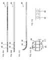
- FIG. 1is a plan view of a vertebra illustrating schematically a surgical apparatus and method, constructed and operative according to the teachings of the present invention
- FIG. 2is a schematic isometric view of the apparatus of FIG. 1 ;
- FIG. 3Ais an enlarged side view of a first preferred configuration for the distal end of rigid tubes for use in the apparatus of FIG. 1 ;
- FIG. 3Bis an enlarged side view of the distal end of the tube of FIG. 3A showing a trocar inserted within the tube for penetration of tissue;
- FIG. 3Cis a side view of an alternative configuration for a distal end of rigid tubes for use in the apparatus of FIG. 1 ;
- FIG. 3Dis an enlarged side view showing a directional drilling device extending from the distal tube end of FIG. 3A ;
- FIG. 4is a schematic side view illustrating the use of the apparatus of FIG. 1 employed to perform a procedure on an intervertebral disc;
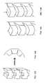
- FIG. 5is a schematic plan view of a preferred net element for use in the procedure of FIG. 3 ;
- FIG. 6is a schematic cross-sectional view showing a preferred mode of releasable connection of beads with a flexible guide element for use in the procedure of FIG. 3 ;
- FIG. 7is a schematic plan view illustrating the release of a chain of beads into the net element of FIG. 4 during performance of the procedure of FIG. 3 ;
- FIGS. 8A and 8Bare schematic plan views illustrating a directional tissue compression device for use in a procedure on a vertebral body according to the teachings of the present invention, the device being shown prior to and during use, respectively;
- FIG. 9is a schematic plan view of a directionally inflating perforated expandably fillable element, constructed and operative according to the teachings of the present invention, for use in a vertebral body subsequent to said direction tissue compression device;
- FIGS. 10A and 10Bare schematic side views of a tunneling system, constructed and operative according to a further aspect of the present invention, shown prior to and during formation of an arcuate tunnel, respectively;
- FIG. 10Cis an enlarged view of a portion of a tunneling device from the tunneling system of FIG. 10A ;
- FIGS. 11A and 11Bare top and side views, respectively, of a tunneling device suitable for use in the tunneling system of FIGS. 10A and 10B in a substantially straight state;
- FIG. 11Cis a view similar to FIG. 11B showing the tunneling device in an arcuate state
- FIG. 11Dis an enlarged cross-sectional view of a small region of FIG. 11B ;
- FIG. 11Eis an enlarged view of a small region of FIG. 11A ;
- FIG. 12Ais a schematic isometric view of an alternative implementation of the tunneling device of FIGS. 10A and 10B in a substantially straight state;
- FIG. 12Bis a side view of the device of FIG. 12A in an arcuate state
- FIGS. 13A and 13Bare schematic isometric views of a further alternative implementation of the tunneling device of FIGS. 10A and 10B in a substantially straight state, showing non-hollow and hollow implementations, respectively;
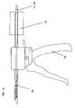
- FIG. 14is a schematic illustration of the tunneling system of FIGS. 10A and 10B for use in the apparatus of FIGS. 1-9 and including a drive device for advancing the tunneling device;
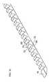
- FIG. 15is a schematic isometric view of a non-hollow implementation of the tunneling device of FIGS. 10A and 10B .
- the present inventionis an apparatus and method for minimally invasive spinal surgery.
- the inventionalso provides surgical techniques, advantageously implemented using the apparatus and method of the invention, for intervertebral disc repair and for vertebral body repair.
- FIG. 1illustrates a preferred apparatus and corresponding method for performing various minimally invasive spinal surgery (MISS) procedures according to the teachings of the present invention.
- the preferred surgical method of the present inventionis based on inserting an elongated flexible guide element 10 such that the guide element passes in through a first lateral posterior incision, passes through the spinal column anterior to the spinal cord, and passes out through a second lateral posterior incision contralateral to the first incision.
- the guide element 10is then employed to guide at least one element to a desired position within the spinal column as part of the surgical procedure.
- the guide elementthus placed functions in a manner analogous to the ubiquitous guide wire of vascular surgery, defining a precise path along which other elements or devices can be advanced in a precise and repeatable manner.
- the deviceeffectively provides a platform for manipulation of tissues and introduction of implants anterior to the spinal cord.
- the elements or devicesmay travel along using the guide element as a stationary rail, or the guide element itself may be advanced through the spinal column with pull-through functionality.
- the guide elementprovides a well defined reference location within the spinal column for performance of a MISS procedure.
- the guide elementalso facilitates bilateral fixation at the end of the procedure by attachment of portions of the guide element to bone surfaces on both sides of the vertebra.
- the path of guide element 10 through the spinal columnis preferably defined by a pair of hollow rigid tubes 12 , 14 inserted through contra-lateral incisions in the back of a subject.
- the soft tissue through which the incisions are madehas been omitted from the drawings.
- Suitable incisions for such a lateral posterior approachare well known, and can typically be implemented as a small stab wound.
- a rigid coupling 16is configured for rigidly coupling tubes 12 , 14 such that the tubes converge towards their distal (inserted) ends but maintain a predefined gap between their ends. This gap is preferably in the range of 15-20 millimeters wide.
- Guide element 10is then deployed passing in through a first of the hollow tubes 12 , traversing the gap between the distal ends, and passing out through a second of the hollow tubes 14 .
- the portion of the guide element traversing the gapdefines a working region within the spinal column, as will become clearer from the subsequent examples.
- FIG. 2illustrates in more detail a preferred implementation of the apparatus.
- first and second tubes 12 , 14are preferably implemented as substantially straight hollow tubes with inward-facing distal openings such that the distal openings face each other across the gap. This facilitates insertion of guide element 10 passing across the gap and helps to clearly delimit the sides of the gap.
- the distal ends of tubes 12 , 14are implemented as inward facing beveled ends.
- the distal ends of first and second tubes 12 , 14are curved towards the gap as illustrated in FIG. 3C .
- each tube 12 , 14has an enlarged clamping portion 12 a, 14 a with a flat surface 18 defining a clamping orientation relative to rigid coupling 16 .
- Clamping portions 12 a and 14 aare preferably also asymmetric under reflection so as to be non-interchangeable with each other.
- each clamping portionhas a generally triangular asymmetric cross-section where only one side is flat to provide clamping surface 18 and the remainder of the surfaces are curved.
- rigid coupling 16is implemented with eccentric lever clamps 20 deployed in slots 22 .
- Thisallows quick clamping in a range of relative spacings between the rigid tubes, but in a predefined angular relation defined by clamping surfaces of clamps 20 .
- the angular relationis typically inclined inwards towards a central plane through the device at between 15°-25°, corresponding to an angle of conversion of the two tubes in the range of 30°-50°.
- many other clamping configurationsmay equally be used, optionally giving additional degrees of freedom of adjustment such as an angular adjustment of the rigid tubes.
- rigid coupling 16may be mechanically linked through an adjustable clamping structure (not shown) to a fixed reference surface such as an operating table to provide additional stabilization and rigidity during performance of a procedure.
- the rigid couplingmay be temporarily anchored to the subject's body via axial skeletal features. Suitable adjustable clamping structures for both of these types of clamping are known in the art and will not be described herein.
- a wide range of materialsmay be used to produce rigid tubes 12 , 14 and rigid coupling 16 .
- Particularly preferred examplesinclude, but are not limited to, surgical steel and other biocompatible metals, metal alloys and rigid polymers.
- the diameter of the tubesis typically in the range of 2-6 mm, and most preferably in the range of 3-5 mm.
- a removable trocar 24is removably received within each tube 12 , 14 ( FIG. 3B ) to facilitate insertion of the first and second tubes through soft tissues of the subject's back to reach the desired position. The trocar is then withdrawn to free the lumen of the tube for insertion of the guide element.
- the apparatus and method of the present inventionare useful for performance of a wide range of MISS procedures, including many known procedures conventionally performed by other surgical techniques. These include procedures performed both on intervertebral discs and on the vertebral body.
- rigid tubes 12 , 14are preferably inserted immediately above the transverse processes of the vertebra below the disc in question as shown in FIG. 4 .
- preferred positioning for insertion of rigid tubes 12 , 14is via small holes drilled through the pedicle on each side of the vertebra.
- the apparatuspreferably also includes a retractable tunneling or drilling system. A particularly preferred implementation of a tunneling system constructed and operative according to the teachings of the present invention will be described below with reference to FIGS. 10A-15 .
- a conventional drilling devicesuch as drilling device 26 ( FIG. 3D ), removably associated with one of tubes 12 , 14 so as to drill a connecting channel through the gap for insertion of the guide element.
- retractable drilling device 26is preferably implemented as a directional drilling device configured for drilling in a direction non-parallel with a central bore of the tube.
- thermal or laser ablationmay be used for this purpose, mechanical drills are believed to be preferable to avoid risk of thermal damage to surrounding tissue (disc, bone and nerves).
- suitable mechanical directional drilling devicesboth steerable and with a fixed lateral curvature, are known in the field and will not be described herein in detail.
- two suitable designsare described in U.S. Pat. No. 6,558,386 which is hereby incorporated by reference, particularly with reference to FIGS. 9-10 thereof.
- guide element 10itself, it should be noted that the guide element may be implemented in many different configurations varying in shape, gauge, materials and deployment according to the requirements of each given procedure to be performed. Furthermore, various different guide element configurations may be used during the course of a single procedure, either by withdrawing a first guide element and deploying an alternative guide element or by connecting different guide element configurations sequentially such that each section pulled out draws the subsequent section of the guide element into position traversing the gap within the spinal column as required.
- the guide elementis preferably chosen to be asymmetric under rotations of less than 180° about its length, thereby providing a defined orientation for devices introduced within the spinal column.
- a simple example of a preferred asymmetric formis a flat strip. Other examples will be discussed below in the context of certain specific applications.
- Preferred materials for the guide elementare typically flexible biocompatible polymer materials such as PEEK or resilient metals or metal alloys such as spring steel or superelastic nitinol alloys.
- FIGS. 5-7a preferred technique for repair of a damaged intervertebral disc will now be described. It should be appreciated that, while the technique is described in a particularly preferred context implemented using the surgical method of the present invention, various aspects of the technique are believed to be patentable in their own right even if implemented using otherwise conventional surgical methods.
- the disc repair technique of the present inventionis performed by introducing into the nucleus of a damaged disc a plurality of beads of material chosen to have surface properties which encourage generation of scar tissue.
- the fillingconforms readily to the geometry of the load-transfer surfaces of adjacent vertebrae and immediate provides load-bearing support in a manner similar to that described in U.S. Pat. No. 5,702,454.
- the use of surfaces for encouraging generation of scar tissueinitiates a physiological process in which scar tissue fills the gaps between the beads, becoming a significant if not primary contributor to the physical properties of the disc nucleus.
- Scar tissuebeing highly fibrous, moderately flexible and having few nerves has been found by the present inventor to be an ideal substitute for the natural tissue of the inner disc.
- the beadsare preferably formed primarily, or entirely, from material exhibiting surface pores of width 50-100 microns, and most preferably in the 70-80 micron range.
- a preferred but non-limiting example of a biocompatible material exhibiting pores of this sizeis polypropylene.
- the beadsare preferably rounded to ensure that they conform readily to the shape of the space to be filled.
- substantially spherical beadsare used.
- a preferred diameter (or maximum dimension for non-spherical beads)is typically in the range of 1-10 mm, and most preferably around 1-5 mm.
- this aspect of the present inventionpreferably employs a net element configured to contain the plurality of beads within a defined containment region.
- the net elementmust clearly have openings sufficiently fine to prevent passage of the filling beads.
- the openings of the net elementare sufficiently large to permit penetration of tissue cells and small blood vessels.
- a preferred range of sizes for the net element openingsis up to about 0.5 mm.
- net element 30is attached to, or integrally formed with, an opening in the side of a piece of flexible tubing such that the portions either side of the net element provide first and second tubular flexible elongated fixation appendages 32 and 34 .
- the functions of these appendageswill be described below.
- each bead 36is formed with a shaped recess and elongated guide element 10 is formed with a complementary sequence of projections or projecting ridge 38 forming a releasable “snap” connection.
- releasable connection configurationsmay also be used.
- net element 30is preferably provided with a release configuration deployed to effect release of the beads from guide element 10 .
- the release configurationis implemented as a forked ramp or wedge 40 located within the net element near the point where guide element 10 passes out through appendage 34 .
- beads 36are interconnected into strings or chains of beads by small interconnecting links.
- the linksare integrally molded with the beads.
- the beadsmay be separately formed and then strung on a separate connecting strand.
- net element 30is advanced in a folded state around guide element 10 until it reaches a position with the net deployed in the gap between the rigid tubes and appendages 32 and 34 deployed within tubes 12 and 14 , respectively, as shown in FIG. 7 .
- This positioningmay be reliably determined by appropriate length markings on parts of appendages 32 and/or 34 extending outwards from the rigid tubes indicating the distance from the beginning of the net element. Additionally, or alternatively, imaging techniques such as fluoroscopy may be used to verify the positioning.
- radio-opaque reference markersare preferably incorporated into the net element at predefined positions.
- the portion of the guide element carrying beads 36is advanced (typically pulled-through) to draw the beads into the internal volume of the net element. As they reach release configuration 40 , the beads become detached from the guide element, thereby freeing a string of beads as shown in FIG. 7 .
- the deployment of the beads on guide element 10is such that a predefined length of guide element corresponds to a quantity of beads sufficient to fill a predefined volume. For example, a given length of, for example, 5 cm of the guide element with beads may correspond to a volume of 1 cc.
- the corresponding required quantity of beadsmay be determined simply by marking-off a required length of the bead-carrying guide element to be used, and possibly severing the beads from the guide element beyond that length.
- FIGS. 8A , 8 B and 9there is illustrated a preferred apparatus and technique for restoration of a collapsed or damaged vertebral body.
- FIGS. 8A , 8 B and 9there is illustrated a preferred apparatus and technique for restoration of a collapsed or damaged vertebral body.
- various aspects of the apparatus and techniqueare believed to be patentable in their own right even if implemented using otherwise conventional surgical methods.
- a directional tissue compression deviceis introduced into the vertebral body and operated to apply pressure to a transverse slice of tissue within the vertebral body so as to form a cavity anterior to the guide element. Then, once a slice-shaped cavity is formed, an expandably fillable element is introduced into the cavity and inflated with a filling material so as to increase an axial dimension of the vertebral body.
- the technique of the present inventionalso addresses a further problem of cement leakage common to conventional procedures.
- conventional vertebral body height restoration techniquestypically employ an inflatable balloon which is inserted temporarily in order to achieve the desired height restoration. The balloon is then deflated and removed, and PMMA or other cement is injected into the cavity from which the balloon was removed.
- Such techniquessuffer from lack of control over the dispersion of the cement which may leak from the vertebral body, or may set with various sharp or abrasive surface features which may subsequently pose a risk of damage to adjacent tissue or blood vessels.
- a permanent filling materialsuch as cement
- the expandably fillable elementincludes perforations dispersed over its surface such that the introducing a filling material releases a small proportion (typically less than 20%, and most preferably no more than 10%) of the filling material to enhance fixation of the expandably fillable element to the bone of the surrounding vertebral body.
- rigid tubes 12 and 14are first inserted through respective bores drilled in first and second pedicles, respectively, of the vertebra requiring reconstruction.
- Directional drillingis then typically used to form a channel across the gap between distal ends of the tubes, and guide element 10 is inserted through the vertebral body passing in through the first pedicle of the vertebra, across within the vertebral body and out through the second pedicle of the vertebra.
- FIGS. 8A and 8Billustrate a particularly simple but effective preferred embodiment of the direction tissue compression device, designated 42 .
- Device 42includes a relatively rigid housing 44 with an arcuate form and having a lateral opening 46 formed near its tip.
- Housing 44typically has a rectangular cross-sectional shape, although other shapes such as an oval shape are also possible. Some degree of flexibility may be required to allow housing 44 to be inserted along rigid tube 12 . Within housing 44 is deployed a flexible strip.
- the mechanical properties of a flat stripare that it is relatively flexible for in-plane bending but resistant to sideways bending or torsional distortion.
- the flexible strip 48As a result, as the flexible strip 48 is advanced, confined within housing 44 , it tends to bulge outwards directionally from opening 46 as shown in FIG. 8B , thereby applying pressure directionally to a slice of cancellous bone tissue lying anterior to the device (i.e., forward from the guide element and away from the spinal cord) and bounded by an outer arcuate profile, so as to open a corresponding slice-shaped cavity.
- the term “slice” or “slice-shaped”is used herein in the description and claims to refer to any three-dimensional form bounded in part by two substantially parallel, substantially planar faces, and independent of the shape of the remaining boundaries. In the case of a cavity or void, the bounding surfaces are clearly the inward facing surfaces of the surrounding material.
- the term “height” and “axial”are used to refer to a dimension and direction, respectively, substantially parallel to the spinal cord.
- the term “transverse”is used to refer to a plane substantially perpendicular to the spinal cord.
- both housing 44 and flexible strip 48may be formed from the same material with the differing degrees of flexibility being provided by suitable design of the dimensions and/or structure of the elements.
- an expandably fillable elementis introduced into the cavity.
- a preferred implementation of an expandably fillable element, designated 50is shown here schematically in FIG. 9 .
- the expandably fillable elementexpands during filling to initially deploy itself evenly over a large proportion of the lateral dimension of the vertebral body, thereby ensuring that the subsequent continued expansion acts substantially uniformly to increase an axial dimension of the vertebral body.
- expandably fillable element 50includes a pair of flexible elongated fixation appendages 52 , 54 for providing precise positioning of expandably fillable element 50 prior to inflation and bilateral fixation on completion of the procedure, all in a manner analogous in that of appendages 32 , 34 described above.
- appendages 52 and 54serves also as a filling conduit for introducing filling material into expandably fillable element 50 .
- a wide range of biocompatible filling materialsmay be used to inflate expandably fillable element 50 .
- the filling materialmay be a liquid, a gel, a paste or powdered or granulated solids.
- Preferred examplesinclude, but are not limited to, PMMA and other cements or inert fillers, and/or various material or medicaments used for promoting bone growth or regeneration.
- expandably fillable element 50includes a plurality of perforations 56 such that a small proportion of the filling material is released from the surface of expandably fillable element 50 during the filling process to enhance fixation of the expandably fillable element in the surrounding tissue.
- the size of the perforationsare chosen according to the physical properties of the filling material in order to ensure that only a small proportion is released.
- This fixation enhancementmay be an immediate, or nearly immediate mechanical anchoring effect such as in the example of a bone cement filler, or may be part of a slower physiological process such as in the case of a bone regenerating material.
- FIGS. 10A-15there is illustrated a further aspect of the present invention which provides a tunneling system for forming an arcuate tunnel through biological tissue.
- This systemis applicable to a wide range of applications in orthopedic and other types of surgery where it is desired to form an arcuate channel through biological tissue at some point within a human or animal body.
- the systemmay be used to advantage for forming a channel to bridge the gap between rigid tubes 12 , 14 . While it will be described by way of a non-limiting example in the aforementioned context, it should be appreciated that the system may be adapted, including scaling up or scaling down of dimensions, and adjustment of cross-sectional shape and/or radius of curvature, for use in other contexts.
- the tunneling systemincludes a delivery conduit 60 having an inner channel 62 and an open end 64 .
- At least part of inner channel 62is substantially straight, meaning that it is either straight or at least has a radius of curvature significantly greater than that of the arcuate channel to be formed.
- Slidingly deployed within inner channel 62is a tunneling device 66 .
- at least a distal portion of tunneling device 66is formed from a series of substantially rigid elements 68 interconnected at pivotal interconnection regions 70 which are configured to transfer compressive forces between adjacent of the elements and provide a series of parallel effective hinge axes.
- Each element 68also exhibits at least one contact surface 72 disposed for abutting a corresponding region 74 of an adjacent one of elements 68 so as to define a maximum deflection of relative pivotal motion between adjacent of the elements.
- the result of this structureis that, when the distal portion of tunneling device 66 is deployed within inner channel 62 , at least part of the distal portion assumes a substantially straight state ( FIG. 10A ) with contact surfaces 72 and the corresponding regions 74 separated. Then, as the distal portion is advanced beyond open end 64 into the biological tissue, elements 68 are deflected to the maximum deflection so that a part of the distal portion beyond open end 64 assumes a pre-defined substantially arcuate state ( FIG. 10B ).
- the tunneling system of the present inventionprovides a particularly elegant and effective solution for forming an arcuate tunnel through tissue.
- the substantially straight state of the tunneling deviceallows it to be inserted along a straight delivery conduit to reach the desired location within the body for starting the arcuate channel.
- resistance of the tissue itselfoptionally supplemented or replaced by a mechanical biasing arrangement, causes elements 68 to close against each other, thereby forming a mechanically stable arcuate formation which can be driven from the rear by a compressive driving force to forcibly generate an arcuate channel through the tissue.
- the pivotal interconnection regions 70may be implemented in many different ways.
- the interconnection regionsare hinge structures which attach separately formed elements 68 .
- discrete elements 68are attached along a common flexible backing strip.
- the interconnection regionsare integrally formed with elements 68 .
- the structureis preferably integrally formed as an elongated body with a plurality of transverse slots spaced along its length. Regions between adjacent slots thus provide substantially rigid elements 68 and regions around the slots providing the pivotal interconnection regions 70 .
- metal materialIn the case of metal or metal alloy implementations (referred to generically as “metallic material”), this is typically implemented by machining a length of solid material or a hollow profile to form transverse slots. In the case of polymer materials, the entire structure may be integrally molded or formed by other conventional polymer production techniques.
- parallel effective hinge axesit will be noted that this includes both well defined hinge axes such as that of a hinge-pin structure and a distributed flexion hinge where a relatively thin region of flexible material provides freedom of pivotal movement.
- the effective hinge axisis defined herein as the axis of a hinge-pin structure which would most closely approximate the pivotal freedom of movement provided by the flexion hinge.
- the tunneling device of the present inventionhas an open-ended hollow elongated body.
- the deviceoperates like an apple-core removing tool, punching out tissue lying in its arcuate path so that the tissue accumulates within the hollow profile of the device.
- the leading edges which circumscribe the end of the opening of the hollow profilemay be sharpened to form a cutting edge.
- This configurationis particularly suitable for tunneling through relatively soft tissue, such as for the repair of damaged intervertebral discs as described above with reference to FIGS. 5-7 , although it is also useful for a wide range of other applications.
- At least a distal tip of the tunneling device of the present inventionis non-hollow.
- the entire devicemay be formed from a solid block slotted as described above.
- An example of a non-hollow tunneling deviceis shown schematically in FIG. 15 .
- This implementationis particularly suited for tunneling through cancellous bone, such as for the restoration of a collapsed or damaged vertebral body as described above with reference to FIGS. 8A , 8 B and 9 , although it is also useful for a wide range of other applications.
- Tunneling device 66may be implemented in a large number of cross-sectional shapes.
- the elongated body of the devicehas a substantially rectangular cross-sectional outline, optionally square.
- Alternative cross-sectional shapesinclude, but are not limited to, triangular, rhomboid, semicircular and otherwise-modified circular.
- the cross-sectional shapepreferably has at least one flat side which serves as a base within which (or close to which) the hinge axes lie.
- contact surfaces 72 and corresponding regions 74may be implemented in many different ways so long as they provide a well defined maximum-deflection abutment position between adjacent elements 68 .
- the contact surfaces and corresponding regionsare defined by facing sides of transverse slots which are substantially V-shaped.
- the transverse slotsare substantially parallel-sided, having either a rectangular or U-shaped form as viewed from the side ( FIGS. 11B and 11D ).
- contact surfaces 72 and corresponding regions 74are configured to provide some degree of interlocking, particularly configured to offer resistance against lateral or torsional displacement of adjacent elements 68 .
- each element 68preferably features at least two non-coplanar contact surfaces 72 and corresponding regions 74 .
- the contact surfacesdefine an angular ridge and the surfaces of corresponding regions 74 define a complementary trough. This provides a positive interlocking structure in the arcuate state, as indicated by the dashed lines showing overlap in FIG. 12B .
- FIGS. 12Acontact surfaces 72 and corresponding regions 74 are configured to provide some degree of interlocking, particularly configured to offer resistance against lateral or torsional displacement of adjacent elements 68 .
- each element 68preferably features at least two non-coplanar contact surfaces 72 and corresponding regions 74 .
- the contact surfacesdefine an angular ridge and the surfaces of corresponding regions 74 define a complementary trough. This provides a positive interlocking structure in the arcuate state, as indicated by the
- tunneling device 66In order to ensure deflection of the tunneling device into its arcuate form as it advances, tunneling device 66 preferably terminates in a distal tip 76 having a bevel angle ⁇ inclined so as to tend to deflect the elements towards its arcuate state when advanced.
- Bevel angle ⁇defined as the angle between the plane of the beveled end surface and a longitudinal axis of the tunneling device when in the substantially straight state, is preferably between 20° and 70°. This beveled tip ensures that the device reliably assumes its arcuate state as it is advanced into biological tissue due to the resistance of the tissue itself.
- the tunneling devicemay include a tensioning element (not shown) deployed along at least part of a length of the tunneling device for biasing adjacent of the elements to the maximum deflection.
- a tensioning elementdeployed along at least part of a length of the tunneling device for biasing adjacent of the elements to the maximum deflection.
- the tensioning elementmay be implemented as a resilient cable extending along a channel within the tunneling device.
- a substantially non-stretchable cablemay be used with manual or other actuation to selectively apply a force to deflect the device.
- the tunneling system of the present inventionpreferably further includes a drive device configured to advance the tunneling device relative to the delivery conduit.
- a drive deviceconfigured to advance the tunneling device relative to the delivery conduit.
- a manually operable drive device 78configured such that repeated manual operation of a trigger handle causes stepwise advancing of tunneling device 66 relative to conduit 60 .
- drive device 78operates as a sprocket drive with at least one projecting feature (not shown) for engaging a corresponding series of recesses 80 ( FIGS. 11D and 11E ) formed along at least part of the length of tunneling device 66 .
- conduit 60may be implemented as hollow rigid tube 12 clamped by rigid coupling 16 .
- the second hollow rigid tube 14has been omitted here.
Landscapes
- Health & Medical Sciences (AREA)
- Orthopedic Medicine & Surgery (AREA)
- Surgery (AREA)
- Life Sciences & Earth Sciences (AREA)
- Biomedical Technology (AREA)
- Public Health (AREA)
- Neurology (AREA)
- Engineering & Computer Science (AREA)
- Veterinary Medicine (AREA)
- Heart & Thoracic Surgery (AREA)
- Medical Informatics (AREA)
- Molecular Biology (AREA)
- Animal Behavior & Ethology (AREA)
- General Health & Medical Sciences (AREA)
- Nuclear Medicine, Radiotherapy & Molecular Imaging (AREA)
- Dentistry (AREA)
- Oral & Maxillofacial Surgery (AREA)
- Prostheses (AREA)
- Surgical Instruments (AREA)
Abstract
Description
Claims (20)
Priority Applications (22)
| Application Number | Priority Date | Filing Date | Title |
|---|---|---|---|
| US11/028,655US7503920B2 (en) | 2004-08-11 | 2005-01-05 | Spinal surgery system and method |
| ES05820803TES2431120T3 (en) | 2005-01-05 | 2005-12-28 | Straight introduction device that adopts a curved configuration |
| EP05820803.4AEP1833375B1 (en) | 2005-01-05 | 2005-12-28 | Straight introduction device that assumes curved configuration |
| EP13165979.9AEP2623056B1 (en) | 2005-01-05 | 2005-12-28 | Device for introduction into a body |
| US11/813,213US7918874B2 (en) | 2004-08-11 | 2005-12-28 | Devices for introduction into a body along a substantially straight guide to form a predefined curved configuration, and methods employing same |
| CA2587439ACA2587439C (en) | 2005-01-05 | 2005-12-28 | Devices for introduction into a body via a substantially straight conduit to form a predefined curved configuration, and methods employing such devices |
| PCT/IL2005/001393WO2006072941A2 (en) | 2005-01-05 | 2005-12-28 | Straight introduction device that assumes curved configuration |
| EP13166005.2AEP2633829B1 (en) | 2005-01-05 | 2005-12-28 | Device for introduction into a body along a substantially straight elongated-element-restricting structure |
| JP2007548961AJP2008531071A (en) | 2005-01-05 | 2005-12-28 | Device for introducing a predetermined curvilinear structure by being introduced into an object via a substantially straight conduit and method of using this device |
| IL183156AIL183156A (en) | 2005-01-05 | 2007-05-13 | Devices for introduction into a body via a substantially straight conduit to form a predefined curved configuration and methods employing such devices |
| US12/960,503US8236029B2 (en) | 2004-08-11 | 2010-12-05 | Devices for introduction into a body via a substantially straight conduit to for a predefined curved configuration, and methods employing such devices |
| US12/965,882US8241328B2 (en) | 2004-08-11 | 2010-12-12 | Devices for introduction into a body via a substantially straight conduit to form a predefined curved configuration, and methods employing such devices |
| US13/081,518US8906098B2 (en) | 2004-08-11 | 2011-04-07 | Devices for introduction into a body via a substantially straight conduit to form a predefined curved configuration, and methods employing such devices |
| US13/093,883US8206423B2 (en) | 2004-08-11 | 2011-04-26 | Devices for introduction into a body via a substantially straight conduit to form a predefined curved configuration, and methods employing such devices |
| US13/093,889US8486109B2 (en) | 2004-08-11 | 2011-04-26 | Devices for introduction into a body via a substantially straight conduit to form a predefined curved configuration, and methods employing such devices |
| JP2012025498AJP5390646B2 (en) | 2005-01-05 | 2012-02-08 | Device for introducing a predetermined curvilinear structure by being introduced into an object via a substantially straight conduit and method of using this device |
| US13/405,306US8465524B2 (en) | 2004-08-11 | 2012-02-26 | Devices for introduction into a body via a substantially straight conduit to form a predefined curved configuration, and methods employing such devices |
| US13/490,483US8597330B2 (en) | 2004-08-11 | 2012-06-07 | Devices for introduction into a body via a substantially straight conduit to form a predefined curved configuration, and methods employing such devices |
| JP2013027094AJP5671080B2 (en) | 2005-01-05 | 2013-02-14 | Device for introducing a predetermined curvilinear structure by being introduced into an object via a substantially straight conduit and method of using this device |
| US13/860,545US8900235B2 (en) | 2004-08-11 | 2013-04-11 | Devices for introduction into a body via a substantially straight conduit to form a predefined curved configuration, and methods employing such devices |
| JP2013209658AJP5736431B2 (en) | 2005-01-05 | 2013-10-04 | Device for introducing a predetermined curvilinear structure by being introduced into an object via a substantially straight conduit and method of using this device |
| US14/556,295US20150088139A1 (en) | 2004-08-11 | 2014-12-01 | Devices for introduction into a body via a substantially straight conduit to form a predefined curved configuration, and methods employing such devices |
Applications Claiming Priority (2)
| Application Number | Priority Date | Filing Date | Title |
|---|---|---|---|
| US10/915,478US20060036241A1 (en) | 2004-08-11 | 2004-08-11 | Spinal surgery system and method |
| US11/028,655US7503920B2 (en) | 2004-08-11 | 2005-01-05 | Spinal surgery system and method |
Related Parent Applications (4)
| Application Number | Title | Priority Date | Filing Date |
|---|---|---|---|
| US10/915,478Continuation-In-PartUS20060036241A1 (en) | 2004-08-11 | 2004-08-11 | Spinal surgery system and method |
| US10/915,478ContinuationUS20060036241A1 (en) | 2004-08-11 | 2004-08-11 | Spinal surgery system and method |
| PCT/IL2005/001393Continuation-In-PartWO2006072941A2 (en) | 2004-08-11 | 2005-12-28 | Straight introduction device that assumes curved configuration |
| US10915478Continuation-In-Part | 2005-12-28 |
Related Child Applications (8)
| Application Number | Title | Priority Date | Filing Date |
|---|---|---|---|
| US11/813,213Continuation-In-PartUS7918874B2 (en) | 2004-08-11 | 2005-12-28 | Devices for introduction into a body along a substantially straight guide to form a predefined curved configuration, and methods employing same |
| US11/813,213ContinuationUS7918874B2 (en) | 2004-08-11 | 2005-12-28 | Devices for introduction into a body along a substantially straight guide to form a predefined curved configuration, and methods employing same |
| PCT/IL2005/001393Continuation-In-PartWO2006072941A2 (en) | 2004-08-11 | 2005-12-28 | Straight introduction device that assumes curved configuration |
| PCT/IL2005/001393ContinuationWO2006072941A2 (en) | 2004-08-11 | 2005-12-28 | Straight introduction device that assumes curved configuration |
| US10915478Continuation-In-Part | 2005-12-28 | ||
| US10915478Continuation | 2005-12-28 | ||
| US81321307AContinuation-In-Part | 2004-08-11 | 2007-07-02 | |
| US81321307AContinuation | 2004-08-11 | 2007-07-02 |
Publications (2)
| Publication Number | Publication Date |
|---|---|
| US20060036273A1 US20060036273A1 (en) | 2006-02-16 |
| US7503920B2true US7503920B2 (en) | 2009-03-17 |
Family
ID=46321744
Family Applications (2)
| Application Number | Title | Priority Date | Filing Date |
|---|---|---|---|
| US11/028,655Active2026-07-14US7503920B2 (en) | 2004-08-11 | 2005-01-05 | Spinal surgery system and method |
| US11/813,213Expired - Fee RelatedUS7918874B2 (en) | 2004-08-11 | 2005-12-28 | Devices for introduction into a body along a substantially straight guide to form a predefined curved configuration, and methods employing same |
Family Applications After (1)
| Application Number | Title | Priority Date | Filing Date |
|---|---|---|---|
| US11/813,213Expired - Fee RelatedUS7918874B2 (en) | 2004-08-11 | 2005-12-28 | Devices for introduction into a body along a substantially straight guide to form a predefined curved configuration, and methods employing same |
Country Status (1)
| Country | Link |
|---|---|
| US (2) | US7503920B2 (en) |
Cited By (138)
| Publication number | Priority date | Publication date | Assignee | Title |
|---|---|---|---|---|
| US20060095059A1 (en)* | 2004-10-15 | 2006-05-04 | Baxano, Inc. | Devices and methods for tissue modification |
| US20070204064A1 (en)* | 2004-03-23 | 2007-08-30 | David Mail | Optimally adapting multimedia content for mobile subscriber device playback |
| US20070213733A1 (en)* | 2004-10-15 | 2007-09-13 | Bleich Jeffery L | Mechanical tissue modification devices and methods |
| US20070225703A1 (en)* | 2005-10-15 | 2007-09-27 | Baxano, Inc. | Flexible Tissue Removal Devices and Methods |
| US20080208205A1 (en)* | 2007-02-26 | 2008-08-28 | Paul Edward Kraemer | Cable system and methods |
| US20090069709A1 (en)* | 2007-09-06 | 2009-03-12 | Baxano, Inc. | Method, system, and apparatus for neural localization |
| US20090171381A1 (en)* | 2007-12-28 | 2009-07-02 | Schmitz Gregory P | Devices, methods and systems for neural localization |
| US20090204119A1 (en)* | 2004-10-15 | 2009-08-13 | Bleich Jeffery L | Devices and methods for tissue modification |
| US20090225685A1 (en)* | 2001-01-12 | 2009-09-10 | Liang Shen | Computer-Implemented Voice Markup Language-Based Server |
| US20100042104A1 (en)* | 2008-04-15 | 2010-02-18 | Sridhar Kota | Surgical tools and components thereof |
| US7857813B2 (en) | 2006-08-29 | 2010-12-28 | Baxano, Inc. | Tissue access guidewire system and method |
| US20100331618A1 (en)* | 2009-06-24 | 2010-12-30 | Gyrus Acmi, Inc. | Endoscope shaft frame member with wavy slot |
| US20110015675A1 (en)* | 2009-07-16 | 2011-01-20 | Howmedica Osteonics Corp. | Suture anchor implantation instrumentation system |
| US7887538B2 (en) | 2005-10-15 | 2011-02-15 | Baxano, Inc. | Methods and apparatus for tissue modification |
| US7938830B2 (en) | 2004-10-15 | 2011-05-10 | Baxano, Inc. | Powered tissue modification devices and methods |
| US20110112365A1 (en)* | 2009-06-03 | 2011-05-12 | Gyrus Acmi, Inc. | Endoscope shaft |
| US7963915B2 (en) | 2004-10-15 | 2011-06-21 | Baxano, Inc. | Devices and methods for tissue access |
| US8048080B2 (en) | 2004-10-15 | 2011-11-01 | Baxano, Inc. | Flexible tissue rasp |
| US8062300B2 (en) | 2006-05-04 | 2011-11-22 | Baxano, Inc. | Tissue removal with at least partially flexible devices |
| US8092456B2 (en) | 2005-10-15 | 2012-01-10 | Baxano, Inc. | Multiple pathways for spinal nerve root decompression from a single access point |
| US20120071876A1 (en)* | 2010-09-17 | 2012-03-22 | Stoll E Jordan | Microfracture awl |
| US8192436B2 (en) | 2007-12-07 | 2012-06-05 | Baxano, Inc. | Tissue modification devices |
| US8221424B2 (en) | 2004-12-20 | 2012-07-17 | Spinascope, Inc. | Surgical instrument for orthopedic surgery |
| US8257356B2 (en) | 2004-10-15 | 2012-09-04 | Baxano, Inc. | Guidewire exchange systems to treat spinal stenosis |
| US20120323248A1 (en)* | 2005-06-21 | 2012-12-20 | Brian D. Dross | Arthroscopic method and apparatus for tissue attachment to bone |
| US8366712B2 (en) | 2005-10-15 | 2013-02-05 | Baxano, Inc. | Multiple pathways for spinal nerve root decompression from a single access point |
| US8394102B2 (en) | 2009-06-25 | 2013-03-12 | Baxano, Inc. | Surgical tools for treatment of spinal stenosis |
| US8398641B2 (en) | 2008-07-01 | 2013-03-19 | Baxano, Inc. | Tissue modification devices and methods |
| US8409206B2 (en) | 2008-07-01 | 2013-04-02 | Baxano, Inc. | Tissue modification devices and methods |
| US8419653B2 (en) | 2005-05-16 | 2013-04-16 | Baxano, Inc. | Spinal access and neural localization |
| US8568416B2 (en) | 2004-10-15 | 2013-10-29 | Baxano Surgical, Inc. | Access and tissue modification systems and methods |
| US8613745B2 (en) | 2004-10-15 | 2013-12-24 | Baxano Surgical, Inc. | Methods, systems and devices for carpal tunnel release |
| US8801626B2 (en) | 2004-10-15 | 2014-08-12 | Baxano Surgical, Inc. | Flexible neural localization devices and methods |
| US8821494B2 (en) | 2012-08-03 | 2014-09-02 | Howmedica Osteonics Corp. | Surgical instruments and methods of use |
| US8845639B2 (en) | 2008-07-14 | 2014-09-30 | Baxano Surgical, Inc. | Tissue modification devices |
| US20140371740A1 (en)* | 2008-10-13 | 2014-12-18 | Dfine, Inc. | Systems for treating a vertebral body |
| WO2015004667A1 (en) | 2013-07-11 | 2015-01-15 | Nlt Spine Ltd. | Surgical device with combined differential gearing and deflection mechanism |
| US9060870B2 (en) | 2012-02-05 | 2015-06-23 | Michael J. Milella, Jr. | In-situ formed spinal implant |
| US9078740B2 (en) | 2013-01-21 | 2015-07-14 | Howmedica Osteonics Corp. | Instrumentation and method for positioning and securing a graft |
| US9101386B2 (en) | 2004-10-15 | 2015-08-11 | Amendia, Inc. | Devices and methods for treating tissue |
| US9119639B2 (en) | 2011-08-09 | 2015-09-01 | DePuy Synthes Products, Inc. | Articulated cavity creator |
| US9198765B1 (en) | 2011-10-31 | 2015-12-01 | Nuvasive, Inc. | Expandable spinal fusion implants and related methods |
| US9232954B2 (en) | 2009-08-20 | 2016-01-12 | Howmedica Osteonics Corp. | Flexible ACL instrumentation, kit and method |
| US9247952B2 (en) | 2004-10-15 | 2016-02-02 | Amendia, Inc. | Devices and methods for tissue access |
| US9289240B2 (en) | 2005-12-23 | 2016-03-22 | DePuy Synthes Products, Inc. | Flexible elongated chain implant and method of supporting body tissue with same |
| US9314253B2 (en) | 2008-07-01 | 2016-04-19 | Amendia, Inc. | Tissue modification devices and methods |
| US9320614B2 (en) | 2006-07-31 | 2016-04-26 | DePuy Synthes Products, Inc. | Spinal fusion implant |
| US9333091B2 (en) | 2003-02-14 | 2016-05-10 | DePuy Synthes Products, Inc. | In-situ formed intervertebral fusion device and method |
| US9351739B2 (en) | 2013-12-31 | 2016-05-31 | Amendia, Inc. | Tunneling device |
| US9358120B2 (en) | 2013-03-14 | 2016-06-07 | DePuy Synthes Products, Inc. | Expandable coil spinal implant |
| US9402620B2 (en) | 2013-03-04 | 2016-08-02 | Howmedica Osteonics Corp. | Knotless filamentary fixation devices, assemblies and systems and methods of assembly and use |
| US9421057B2 (en) | 2008-09-30 | 2016-08-23 | Dfine, Inc. | System for use in treatment of vertebral fractures |
| US9421056B2 (en) | 2007-09-28 | 2016-08-23 | DePuy Synthes Products, Inc. | Balloon with shape control for spinal procedures |
| US9439693B2 (en) | 2013-02-01 | 2016-09-13 | DePuy Synthes Products, Inc. | Steerable needle assembly for use in vertebral body augmentation |
| US9445803B2 (en) | 2011-11-23 | 2016-09-20 | Howmedica Osteonics Corp. | Filamentary suture anchor |
| US9456829B2 (en) | 2004-10-15 | 2016-10-04 | Amendia, Inc. | Powered tissue modification devices and methods |
| US9463013B2 (en) | 2013-03-13 | 2016-10-11 | Stryker Corporation | Adjustable continuous filament structure and method of manufacture and use |
| US9498263B2 (en) | 2005-05-27 | 2016-11-22 | DePuy Synthes Products, Inc. | Prosthetic ligament having a helical bone fastener |
| US9526507B2 (en) | 2010-04-29 | 2016-12-27 | Dfine, Inc. | System for use in treatment of vertebral fractures |
| US9572676B2 (en) | 2013-03-14 | 2017-02-21 | DePuy Synthes Products, Inc. | Adjustable multi-volume balloon for spinal interventions |
| US9585761B2 (en) | 2013-03-14 | 2017-03-07 | DePuy Synthes Products, Inc. | Angulated rings and bonded foils for use with balloons for fusion and dynamic stabilization |
| US9592063B2 (en) | 2010-06-24 | 2017-03-14 | DePuy Synthes Products, Inc. | Universal trial for lateral cages |
| US9610117B2 (en) | 2010-04-29 | 2017-04-04 | Dfine, Inc. | System for use in treatment of vertebral fractures |
| US9649116B2 (en) | 2010-11-22 | 2017-05-16 | Dfine, Inc. | System for use in treatment of vertebral fractures |
| US9662149B2 (en) | 2004-03-06 | 2017-05-30 | DePuy Synthes Products, Inc. | Dynamized interspinal implant |
| US9743938B2 (en) | 2010-04-29 | 2017-08-29 | Dfine, Inc. | System for use in treatment of vertebral fractures |
| US9775627B2 (en) | 2012-11-05 | 2017-10-03 | Relievant Medsystems, Inc. | Systems and methods for creating curved paths through bone and modulating nerves within the bone |
| US9788826B2 (en) | 2013-03-11 | 2017-10-17 | Howmedica Osteonics Corp. | Filamentary fixation device and assembly and method of assembly, manufacture and use |
| US9795398B2 (en) | 2011-04-13 | 2017-10-24 | Howmedica Osteonics Corp. | Flexible ACL instrumentation, kit and method |
| US9801725B2 (en) | 2009-12-09 | 2017-10-31 | DePuy Synthes Products, Inc. | Aspirating implants and method of bony regeneration |
| US9901392B2 (en) | 2015-05-11 | 2018-02-27 | Dfine, Inc. | System for use in treatment of vertebral fractures |
| US9918766B2 (en) | 2012-12-12 | 2018-03-20 | Dfine, Inc. | Devices, methods and systems for affixing an access device to a vertebral body for the insertion of bone cement |
| US9931224B2 (en) | 2009-11-05 | 2018-04-03 | DePuy Synthes Products, Inc. | Self-pivoting spinal implant and associated instrumentation |
| US9986992B2 (en) | 2014-10-28 | 2018-06-05 | Stryker Corporation | Suture anchor and associated methods of use |
| US10022245B2 (en) | 2012-12-17 | 2018-07-17 | DePuy Synthes Products, Inc. | Polyaxial articulating instrument |
| US10028784B2 (en) | 2012-03-27 | 2018-07-24 | Dfine, Inc. | Methods and systems for use in controlling tissue ablation volume by temperature monitoring |
| US10058336B2 (en) | 2010-04-08 | 2018-08-28 | Dfine, Inc. | System for use in treatment of vertebral fractures |
| US10080571B2 (en) | 2015-03-06 | 2018-09-25 | Warsaw Orthopedic, Inc. | Surgical instrument and method |
| US10238500B2 (en) | 2002-06-27 | 2019-03-26 | DePuy Synthes Products, Inc. | Intervertebral disc |
| US10398425B2 (en) | 2004-02-09 | 2019-09-03 | Medos International Sarl | Systems and methods for spinal surgery |
| US10433974B2 (en) | 2003-06-30 | 2019-10-08 | DePuy Synthes Products, Inc. | Intervertebral implant with conformable endplate |
| US10463380B2 (en) | 2016-12-09 | 2019-11-05 | Dfine, Inc. | Medical devices for treating hard tissues and related methods |
| US10478241B2 (en) | 2016-10-27 | 2019-11-19 | Merit Medical Systems, Inc. | Articulating osteotome with cement delivery channel |
| US10537435B2 (en) | 2007-05-17 | 2020-01-21 | DePuy Synthes Products, Inc. | Self-distracting cage |
| US10568616B2 (en) | 2014-12-17 | 2020-02-25 | Howmedica Osteonics Corp. | Instruments and methods of soft tissue fixation |
| US10610211B2 (en) | 2013-12-12 | 2020-04-07 | Howmedica Osteonics Corp. | Filament engagement system and methods of use |
| US10624762B2 (en) | 2018-09-07 | 2020-04-21 | Orthorebirth Usa | Bone graft delivery device for minimally invasive surgery |
| US10631884B2 (en) | 2017-06-05 | 2020-04-28 | Conmed Corporation | Multi-barrel drill guide |
| US10660656B2 (en) | 2017-01-06 | 2020-05-26 | Dfine, Inc. | Osteotome with a distal portion for simultaneous advancement and articulation |
| USD902405S1 (en) | 2018-02-22 | 2020-11-17 | Stryker Corporation | Self-punching bone anchor inserter |
| US10888433B2 (en) | 2016-12-14 | 2021-01-12 | DePuy Synthes Products, Inc. | Intervertebral implant inserter and related methods |
| US10905440B2 (en) | 2008-09-26 | 2021-02-02 | Relievant Medsystems, Inc. | Nerve modulation systems |
| US10940016B2 (en) | 2017-07-05 | 2021-03-09 | Medos International Sarl | Expandable intervertebral fusion cage |
| US10966843B2 (en) | 2017-07-18 | 2021-04-06 | DePuy Synthes Products, Inc. | Implant inserters and related methods |
| US10966840B2 (en) | 2010-06-24 | 2021-04-06 | DePuy Synthes Products, Inc. | Enhanced cage insertion assembly |
| US10973652B2 (en) | 2007-06-26 | 2021-04-13 | DePuy Synthes Products, Inc. | Highly lordosed fusion cage |
| US11007010B2 (en) | 2019-09-12 | 2021-05-18 | Relevant Medsysterns, Inc. | Curved bone access systems |
| US11026744B2 (en) | 2016-11-28 | 2021-06-08 | Dfine, Inc. | Tumor ablation devices and related methods |
| US11045331B2 (en) | 2017-08-14 | 2021-06-29 | DePuy Synthes Products, Inc. | Intervertebral implant inserters and related methods |
| US11052237B2 (en) | 2016-11-22 | 2021-07-06 | Dfine, Inc. | Swivel hub |
| US11065046B2 (en) | 2013-08-08 | 2021-07-20 | Relievant Medsystems, Inc. | Modulating nerves within bone |
| US11197681B2 (en) | 2009-05-20 | 2021-12-14 | Merit Medical Systems, Inc. | Steerable curvable vertebroplasty drill |
| US11273050B2 (en) | 2006-12-07 | 2022-03-15 | DePuy Synthes Products, Inc. | Intervertebral implant |
| US11331094B2 (en) | 2013-04-22 | 2022-05-17 | Stryker Corporation | Method and apparatus for attaching tissue to bone |
| US11344424B2 (en) | 2017-06-14 | 2022-05-31 | Medos International Sarl | Expandable intervertebral implant and related methods |
| US11369490B2 (en) | 2011-03-22 | 2022-06-28 | DePuy Synthes Products, Inc. | Universal trial for lateral cages |
| US11426286B2 (en) | 2020-03-06 | 2022-08-30 | Eit Emerging Implant Technologies Gmbh | Expandable intervertebral implant |
| US11426290B2 (en) | 2015-03-06 | 2022-08-30 | DePuy Synthes Products, Inc. | Expandable intervertebral implant, system, kit and method |
| US11446156B2 (en) | 2018-10-25 | 2022-09-20 | Medos International Sarl | Expandable intervertebral implant, inserter instrument, and related methods |
| US11446155B2 (en) | 2017-05-08 | 2022-09-20 | Medos International Sarl | Expandable cage |
| US11452607B2 (en) | 2010-10-11 | 2022-09-27 | DePuy Synthes Products, Inc. | Expandable interspinous process spacer implant |
| US11471210B2 (en) | 2011-12-30 | 2022-10-18 | Relievant Medsystems, Inc. | Methods of denervating vertebral body using external energy source |
| US11471173B2 (en) | 2017-06-05 | 2022-10-18 | Conmed Corporation | Multi-barrel drill guide and anchor deployment assembly |
| US11497619B2 (en) | 2013-03-07 | 2022-11-15 | DePuy Synthes Products, Inc. | Intervertebral implant |
| US11510723B2 (en) | 2018-11-08 | 2022-11-29 | Dfine, Inc. | Tumor ablation device and related systems and methods |
| US11510788B2 (en) | 2016-06-28 | 2022-11-29 | Eit Emerging Implant Technologies Gmbh | Expandable, angularly adjustable intervertebral cages |
| US20220409891A1 (en)* | 2019-05-29 | 2022-12-29 | AtaCor Medical, Inc. | Implantable electrical leads and associated delivery systems |
| US11596522B2 (en) | 2016-06-28 | 2023-03-07 | Eit Emerging Implant Technologies Gmbh | Expandable and angularly adjustable intervertebral cages with articulating joint |
| US11596468B2 (en) | 2002-09-30 | 2023-03-07 | Relievant Medsystems, Inc. | Intraosseous nerve treatment |
| US11602438B2 (en) | 2008-04-05 | 2023-03-14 | DePuy Synthes Products, Inc. | Expandable intervertebral implant |
| US11607321B2 (en) | 2009-12-10 | 2023-03-21 | DePuy Synthes Products, Inc. | Bellows-like expandable interbody fusion cage |
| US11612491B2 (en) | 2009-03-30 | 2023-03-28 | DePuy Synthes Products, Inc. | Zero profile spinal fusion cage |
| US11654033B2 (en) | 2010-06-29 | 2023-05-23 | DePuy Synthes Products, Inc. | Distractible intervertebral implant |
| US11690667B2 (en) | 2012-09-12 | 2023-07-04 | Relievant Medsystems, Inc. | Radiofrequency ablation of tissue within a vertebral body |
| US11737881B2 (en) | 2008-01-17 | 2023-08-29 | DePuy Synthes Products, Inc. | Expandable intervertebral implant and associated method of manufacturing the same |
| US11752009B2 (en) | 2021-04-06 | 2023-09-12 | Medos International Sarl | Expandable intervertebral fusion cage |
| US11850160B2 (en) | 2021-03-26 | 2023-12-26 | Medos International Sarl | Expandable lordotic intervertebral fusion cage |
| USRE49973E1 (en) | 2013-02-28 | 2024-05-21 | DePuy Synthes Products, Inc. | Expandable intervertebral implant, system, kit and method |
| US11986229B2 (en) | 2019-09-18 | 2024-05-21 | Merit Medical Systems, Inc. | Osteotome with inflatable portion and multiwire articulation |
| US12039731B2 (en) | 2020-12-22 | 2024-07-16 | Relievant Medsystems, Inc. | Prediction of candidates for spinal neuromodulation |
| US12082876B1 (en) | 2020-09-28 | 2024-09-10 | Relievant Medsystems, Inc. | Introducer drill |
| US12090064B2 (en) | 2022-03-01 | 2024-09-17 | Medos International Sarl | Stabilization members for expandable intervertebral implants, and related systems and methods |
| US12121738B2 (en) | 2020-05-29 | 2024-10-22 | AtaCor Medical, Inc | Implantable electrical leads and associated delivery systems |
| US12128239B2 (en) | 2014-11-24 | 2024-10-29 | AtaCor Medical, Inc. | Cardiac pacing sensing and control |
| US12296176B2 (en) | 2014-09-04 | 2025-05-13 | AtaCor Medical, Inc. | Cardiac defibrillation |
| US12303166B2 (en) | 2008-09-26 | 2025-05-20 | Relievant Medsystems, Inc. | Methods for accessing nerves within bone |
| US12433668B1 (en) | 2021-11-08 | 2025-10-07 | Relievant Medsystems, Inc. | Impedance stoppage mitigation during radiofrequency tissue ablation procedures |
| US12440346B2 (en) | 2023-03-31 | 2025-10-14 | DePuy Synthes Products, Inc. | Expandable intervertebral implant |
Families Citing this family (79)
| Publication number | Priority date | Publication date | Assignee | Title |
|---|---|---|---|---|
| US6907884B2 (en) | 2002-09-30 | 2005-06-21 | Depay Acromed, Inc. | Method of straddling an intraosseous nerve |
| US7258690B2 (en) | 2003-03-28 | 2007-08-21 | Relievant Medsystems, Inc. | Windowed thermal ablation probe |
| US20060036241A1 (en) | 2004-08-11 | 2006-02-16 | Tzony Siegal | Spinal surgery system and method |
| US8236029B2 (en)* | 2004-08-11 | 2012-08-07 | Nlt Spine Ltd. | Devices for introduction into a body via a substantially straight conduit to for a predefined curved configuration, and methods employing such devices |
| WO2006034436A2 (en) | 2004-09-21 | 2006-03-30 | Stout Medical Group, L.P. | Expandable support device and method of use |
| EP1903949A2 (en) | 2005-07-14 | 2008-04-02 | Stout Medical Group, L.P. | Expandable support device and method of use |
| WO2008103781A2 (en) | 2007-02-21 | 2008-08-28 | Benvenue Medical, Inc. | Devices for treating the spine |
| US8366773B2 (en) | 2005-08-16 | 2013-02-05 | Benvenue Medical, Inc. | Apparatus and method for treating bone |
| AU2006279558B2 (en) | 2005-08-16 | 2012-05-17 | Izi Medical Products, Llc | Spinal tissue distraction devices |
| EP1983917B1 (en)* | 2006-01-27 | 2014-06-25 | Spinal Ventures, LLC | Low pressure delivery system for delivering a solid and liquid mixture into a target site for medical treatment |
| US20070202186A1 (en) | 2006-02-22 | 2007-08-30 | Iscience Interventional Corporation | Apparatus and formulations for suprachoroidal drug delivery |
| EP2023864B1 (en) | 2006-05-01 | 2019-07-10 | Stout Medical Group, L.P. | Expandable support device |
| US8197435B2 (en) | 2006-05-02 | 2012-06-12 | Emory University | Methods and devices for drug delivery to ocular tissue using microneedle |
| US8057481B2 (en) | 2006-11-03 | 2011-11-15 | Innovative Spine, Llc | System and method for providing surgical access to a spine |
| US8840621B2 (en) | 2006-11-03 | 2014-09-23 | Innovative Spine, Inc. | Spinal access systems and methods |
| US7947078B2 (en)* | 2007-01-09 | 2011-05-24 | Nonlinear Technologies Ltd. | Devices for forming curved or closed-loop structures |
| EP2124778B1 (en) | 2007-02-21 | 2019-09-25 | Benvenue Medical, Inc. | Devices for treating the spine |
| US8021429B2 (en) | 2007-03-08 | 2011-09-20 | Zimmer Spine, Inc. | Deployable segmented TLIF device |
| FR2917287B1 (en)* | 2007-06-15 | 2010-09-03 | Ldr Medical | INTERVERTEBRAL PROSTHESIS |
| WO2009019669A1 (en)* | 2007-08-09 | 2009-02-12 | Nonlinear Technologies Ltd. | Device and method for spinous process distraction |
| US20090131867A1 (en) | 2007-11-16 | 2009-05-21 | Liu Y King | Steerable vertebroplasty system with cavity creation element |
| US9510885B2 (en) | 2007-11-16 | 2016-12-06 | Osseon Llc | Steerable and curvable cavity creation system |
| EP2265200B1 (en)* | 2008-03-14 | 2020-05-27 | Mazor Robotics Ltd. | Segmented insert for intervertebral support |
| US20100076476A1 (en) | 2008-07-25 | 2010-03-25 | To John T | Systems and methods for cable-based tissue removal |
| CA2731351A1 (en)* | 2008-07-27 | 2010-02-04 | Nonlinear Technologies Ltd. | Tool and corresponding method for removal of material from within a body |
| US8328812B2 (en)* | 2008-07-27 | 2012-12-11 | NLT-Spine Ltd. | Tool and corresponding method for removal of material from within a body |
| WO2010056895A1 (en) | 2008-11-12 | 2010-05-20 | Stout Medical Group, L.P. | Fixation device and method |
| US20100211176A1 (en) | 2008-11-12 | 2010-08-19 | Stout Medical Group, L.P. | Fixation device and method |
| US8535327B2 (en) | 2009-03-17 | 2013-09-17 | Benvenue Medical, Inc. | Delivery apparatus for use with implantable medical devices |
| US9168047B2 (en)* | 2009-04-02 | 2015-10-27 | John T. To | Minimally invasive discectomy |
| US8801739B2 (en)* | 2009-04-17 | 2014-08-12 | Spine View, Inc. | Devices and methods for arched roof cutters |
| EP2427132B1 (en) | 2009-05-08 | 2015-04-08 | Synthes GmbH | Expandable bone implant |
| US9439691B2 (en)* | 2009-05-22 | 2016-09-13 | Clifford Tribus | Fixation-based surgery |
| US20100312056A1 (en)* | 2009-06-03 | 2010-12-09 | Gyrus, ACMI, Inc. | Endoscope shaft |
| ES2563172T3 (en) | 2009-07-09 | 2016-03-11 | R Tree Innovations, Llc | Flexible intersomatic implant |
| EP2467099B1 (en) | 2009-08-19 | 2019-05-15 | Synthes GmbH | Apparatus for augmenting bone |
| US8277459B2 (en)* | 2009-09-25 | 2012-10-02 | Tarsus Medical Inc. | Methods and devices for treating a structural bone and joint deformity |
| EP2519195A4 (en)* | 2009-12-30 | 2013-09-18 | Spinal Usa Inc | Spinal implant devices and methods |
| WO2011149557A1 (en)* | 2010-05-27 | 2011-12-01 | Stout Medical Group, L.P. | Support device and method for use |
| EP2608747A4 (en) | 2010-08-24 | 2015-02-11 | Flexmedex Llc | Support device and method for use |
| US8758412B2 (en) | 2010-09-20 | 2014-06-24 | Pachyderm Medical, L.L.C. | Integrated IPD devices, methods, and systems |
| KR101877806B1 (en)* | 2010-10-05 | 2018-07-12 | 모건 피. 로리오 | Minimally invasive intervertebral systems and methods |
| JP5996544B2 (en) | 2010-10-15 | 2016-09-21 | クリアサイド・バイオメディカル・インコーポレーテッドClearside Biomedical Incorporated | Eye access device |
| EP2637587A1 (en) | 2010-11-09 | 2013-09-18 | Benvenue Medical, Inc. | Devices and methods for treatment of a bone fracture |
| US9700425B1 (en) | 2011-03-20 | 2017-07-11 | Nuvasive, Inc. | Vertebral body replacement and insertion methods |
| US10548619B2 (en) | 2011-04-29 | 2020-02-04 | Michael P. Wallace | Selective spinal tissue removal apparatus and method |
| US20140012261A1 (en)* | 2012-07-09 | 2014-01-09 | Henry Nita | Ultrasound Enhanced Selective Tissue Removal Method and Apparatus |
| US20140163624A1 (en)* | 2011-08-02 | 2014-06-12 | NLT-Spine Ltd. | Bone Screw with Deflectable Portion |
| EP2747682A4 (en) | 2011-08-23 | 2015-01-21 | Flexmedex Llc | Tissue removal device and method |
| EP2758008B1 (en)* | 2011-09-20 | 2019-09-11 | The University of Toledo | Expandable inter-vertebral cage |
| HK1197964A2 (en) | 2011-12-03 | 2015-02-27 | DePuy Synthes Products, Inc. | Safe cutting heads and systems for fast removal of a target tissue |
| US9226764B2 (en) | 2012-03-06 | 2016-01-05 | DePuy Synthes Products, Inc. | Conformable soft tissue removal instruments |
| EP3593740B1 (en) | 2012-06-20 | 2021-10-06 | Stryker Corporation | System for off-axis tissue manipulation |
| US9445918B1 (en) | 2012-10-22 | 2016-09-20 | Nuvasive, Inc. | Expandable spinal fusion implants and related instruments and methods |
| KR20210133321A (en) | 2012-11-08 | 2021-11-05 | 클리어사이드 바이오메디컬, 인코포레이드 | Methods and devices for the treatment of ocular disease in human subjects |
| US9642629B2 (en) | 2012-11-20 | 2017-05-09 | Specialty Surgical Instrumentation Inc. | System and method for forming a curved tunnel in bone |
| US9241729B2 (en) | 2012-12-14 | 2016-01-26 | DePuy Synthes Products, Inc. | Device to aid in the deployment of a shape memory instrument |
| US10085783B2 (en) | 2013-03-14 | 2018-10-02 | Izi Medical Products, Llc | Devices and methods for treating bone tissue |
| US9795493B1 (en) | 2013-03-15 | 2017-10-24 | Nuvasive, Inc. | Expandable intervertebral implant and methods of use thereof |
| CA2911290C (en) | 2013-05-03 | 2021-07-27 | Clearside Biomedical, Inc. | Apparatus and methods for ocular injection |
| EP3003454B1 (en) | 2013-06-03 | 2020-01-08 | Clearside Biomedical, Inc. | Apparatus for drug delivery using multiple reservoirs |
| EP3021768B1 (en) | 2013-07-19 | 2020-08-19 | DePuy Synthes Products, Inc. | An anti-clogging device for a vacuum-assisted, tissue removal system |
| US20150141998A1 (en)* | 2013-11-19 | 2015-05-21 | Symmetry Medical Manufacturing, Inc | System and method for forming a curved tunnel in bone |
| RU2710491C2 (en) | 2014-06-20 | 2019-12-26 | Клиасайд Байомедикал, Инк. | Device for drug injection into ocular tissue and method for drug injection into ocular tissue |
| USD750223S1 (en) | 2014-10-14 | 2016-02-23 | Clearside Biomedical, Inc. | Medical injector for ocular injection |
| CN104688296B (en)* | 2015-03-18 | 2018-02-02 | 马克 | The snakelike puncture bone cone of one kind orientation |
| WO2016204711A1 (en)* | 2015-06-16 | 2016-12-22 | Spine Wave, Inc. | Instrument and system for placing graft, implant and graft material for minimally invasive posterolateral fusion |
| EP3413851B1 (en) | 2016-02-10 | 2023-09-27 | Clearside Biomedical, Inc. | Packaging |
| WO2017192565A1 (en) | 2016-05-02 | 2017-11-09 | Clearside Biomedical, Inc. | Systems and methods for ocular drug delivery |
| US10973681B2 (en) | 2016-08-12 | 2021-04-13 | Clearside Biomedical, Inc. | Devices and methods for adjusting the insertion depth of a needle for medicament delivery |
| JP7252894B2 (en)* | 2017-02-28 | 2023-04-05 | ボストン サイエンティフィック サイムド,インコーポレイテッド | articulating needle |
| US12090294B2 (en) | 2017-05-02 | 2024-09-17 | Georgia Tech Research Corporation | Targeted drug delivery methods using a microneedle |
| WO2020181211A1 (en)* | 2019-03-07 | 2020-09-10 | Spinal Surgical Strategies, Llc | Bone graft delivery system and method for using same |
| US11213309B2 (en)* | 2019-05-23 | 2022-01-04 | Biosense Webster (Israel) Ltd. | Medical probe having improved maneuverability |
| CN111759400A (en)* | 2020-06-22 | 2020-10-13 | 宁波市第一医院 | A biliary stone hook |
| US11779352B1 (en)* | 2021-02-22 | 2023-10-10 | Advance Research System, Llc | Trans-facet oblique lateral lumbar interbody fusion |
| CN113244027B (en)* | 2021-06-25 | 2021-09-24 | 珠海维尔康生物科技有限公司 | Minimally invasive fence type deformable fusion device used under endoscope |
| CN114732341A (en)* | 2022-04-28 | 2022-07-12 | 北京大学第三医院(北京大学第三临床医学院) | a laryngoscope |
| CN118526248B (en)* | 2024-07-24 | 2025-01-03 | 归创通桥医疗科技股份有限公司 | Tectorial membrane support rupture of membranes device |
Citations (7)
| Publication number | Priority date | Publication date | Assignee | Title |
|---|---|---|---|---|
| US5695513A (en)* | 1996-03-01 | 1997-12-09 | Metagen, Llc | Flexible cutting tool and methods for its use |
| US20050060036A1 (en) | 2003-05-21 | 2005-03-17 | Robert Schultz | Spinal column implant |
| US20050273166A1 (en) | 2004-06-08 | 2005-12-08 | Sweeney Patrick J | Expandable spinal stabilization device |
| DE202006005868U1 (en) | 2006-04-06 | 2006-06-08 | Aesculap Ag & Co. Kg | Implant replacing intervertebral disk, comprising plates divided into movable segments lifted by expanding elements |
| US20060142858A1 (en) | 2004-12-16 | 2006-06-29 | Dennis Colleran | Expandable implants for spinal disc replacement |
| WO2006072941A2 (en) | 2005-01-05 | 2006-07-13 | Tzony Siegal | Straight introduction device that assumes curved configuration |
| US20060247781A1 (en) | 2005-04-29 | 2006-11-02 | Sdgi Holdings, Inc. | Implant |
Family Cites Families (7)
| Publication number | Priority date | Publication date | Assignee | Title |
|---|---|---|---|---|
| US4312337A (en) | 1980-09-08 | 1982-01-26 | Donohue Brian T | Cannula and drill guide apparatus |
| US4941466A (en) | 1987-04-13 | 1990-07-17 | Romano Jack W | Curved bore drilling method and apparatus |
| US5152744A (en) | 1990-02-07 | 1992-10-06 | Smith & Nephew Dyonics | Surgical instrument |
| DE19710392C1 (en) | 1997-03-13 | 1999-07-01 | Haehnel Michael | Slipped disc implant comprises an extensible, hinged or wound body |
| NL1012719C1 (en) | 1999-07-28 | 2001-01-30 | Veldhuizen Dr Ag | Spine prosthesis. |
| US7959634B2 (en) | 2004-03-29 | 2011-06-14 | Soteira Inc. | Orthopedic surgery access devices |
| AU2006279558B2 (en) | 2005-08-16 | 2012-05-17 | Izi Medical Products, Llc | Spinal tissue distraction devices |
- 2005
- 2005-01-05USUS11/028,655patent/US7503920B2/enactiveActive
- 2005-12-28USUS11/813,213patent/US7918874B2/ennot_activeExpired - Fee Related
Patent Citations (7)
| Publication number | Priority date | Publication date | Assignee | Title |
|---|---|---|---|---|
| US5695513A (en)* | 1996-03-01 | 1997-12-09 | Metagen, Llc | Flexible cutting tool and methods for its use |
| US20050060036A1 (en) | 2003-05-21 | 2005-03-17 | Robert Schultz | Spinal column implant |
| US20050273166A1 (en) | 2004-06-08 | 2005-12-08 | Sweeney Patrick J | Expandable spinal stabilization device |
| US20060142858A1 (en) | 2004-12-16 | 2006-06-29 | Dennis Colleran | Expandable implants for spinal disc replacement |
| WO2006072941A2 (en) | 2005-01-05 | 2006-07-13 | Tzony Siegal | Straight introduction device that assumes curved configuration |
| US20060247781A1 (en) | 2005-04-29 | 2006-11-02 | Sdgi Holdings, Inc. | Implant |
| DE202006005868U1 (en) | 2006-04-06 | 2006-06-08 | Aesculap Ag & Co. Kg | Implant replacing intervertebral disk, comprising plates divided into movable segments lifted by expanding elements |
Cited By (318)
| Publication number | Priority date | Publication date | Assignee | Title |
|---|---|---|---|---|
| US20090225685A1 (en)* | 2001-01-12 | 2009-09-10 | Liang Shen | Computer-Implemented Voice Markup Language-Based Server |
| US10238500B2 (en) | 2002-06-27 | 2019-03-26 | DePuy Synthes Products, Inc. | Intervertebral disc |
| US11596468B2 (en) | 2002-09-30 | 2023-03-07 | Relievant Medsystems, Inc. | Intraosseous nerve treatment |
| US9333091B2 (en) | 2003-02-14 | 2016-05-10 | DePuy Synthes Products, Inc. | In-situ formed intervertebral fusion device and method |
| US9801729B2 (en) | 2003-02-14 | 2017-10-31 | DePuy Synthes Products, Inc. | In-situ formed intervertebral fusion device and method |
| US9808351B2 (en) | 2003-02-14 | 2017-11-07 | DePuy Synthes Products, Inc. | In-situ formed intervertebral fusion device and method |
| US11207187B2 (en) | 2003-02-14 | 2021-12-28 | DePuy Synthes Products, Inc. | In-situ formed intervertebral fusion device and method |
| US11096794B2 (en) | 2003-02-14 | 2021-08-24 | DePuy Synthes Products, Inc. | In-situ formed intervertebral fusion device and method |
| US10786361B2 (en) | 2003-02-14 | 2020-09-29 | DePuy Synthes Products, Inc. | In-situ formed intervertebral fusion device and method |
| US10639164B2 (en) | 2003-02-14 | 2020-05-05 | DePuy Synthes Products, Inc. | In-situ formed intervertebral fusion device and method |
| US10583013B2 (en) | 2003-02-14 | 2020-03-10 | DePuy Synthes Products, Inc. | In-situ formed intervertebral fusion device and method |
| US9814590B2 (en) | 2003-02-14 | 2017-11-14 | DePuy Synthes Products, Inc. | In-situ formed intervertebral fusion device and method |
| US9814589B2 (en) | 2003-02-14 | 2017-11-14 | DePuy Synthes Products, Inc. | In-situ formed intervertebral fusion device and method |
| US9925060B2 (en) | 2003-02-14 | 2018-03-27 | DePuy Synthes Products, Inc. | In-situ formed intervertebral fusion device and method |
| US11432938B2 (en) | 2003-02-14 | 2022-09-06 | DePuy Synthes Products, Inc. | In-situ intervertebral fusion device and method |
| US10085843B2 (en) | 2003-02-14 | 2018-10-02 | DePuy Synthes Products, Inc. | In-situ formed intervertebral fusion device and method |
| US10433971B2 (en) | 2003-02-14 | 2019-10-08 | DePuy Synthes Products, Inc. | In-situ formed intervertebral fusion device and method |
| US10376372B2 (en) | 2003-02-14 | 2019-08-13 | DePuy Synthes Products, Inc. | In-situ formed intervertebral fusion device and method |
| US10575959B2 (en) | 2003-02-14 | 2020-03-03 | DePuy Synthes Products, Inc. | In-situ formed intervertebral fusion device and method |
| US10405986B2 (en) | 2003-02-14 | 2019-09-10 | DePuy Synthes Products, Inc. | In-situ formed intervertebral fusion device and method |
| US9439776B2 (en) | 2003-02-14 | 2016-09-13 | DePuy Synthes Products, Inc. | In-situ formed intervertebral fusion device and method |
| US9724207B2 (en) | 2003-02-14 | 2017-08-08 | DePuy Synthes Products, Inc. | In-situ formed intervertebral fusion device and method |
| US9439777B2 (en) | 2003-02-14 | 2016-09-13 | DePuy Synthes Products, Inc. | In-situ formed intervertebral fusion device and method |
| US9730803B2 (en) | 2003-02-14 | 2017-08-15 | DePuy Synthes Products, Inc. | Method of in-situ formation of an intervertebral fusion device |
| US10420651B2 (en) | 2003-02-14 | 2019-09-24 | DePuy Synthes Products, Inc. | In-situ formed intervertebral fusion device and method |
| US10555817B2 (en) | 2003-02-14 | 2020-02-11 | DePuy Synthes Products, Inc. | In-situ formed intervertebral fusion device and method |
| US10492918B2 (en) | 2003-02-14 | 2019-12-03 | DePuy Synthes Products, Inc. | In-situ formed intervertebral fusion device and method |
| US9788963B2 (en) | 2003-02-14 | 2017-10-17 | DePuy Synthes Products, Inc. | In-situ formed intervertebral fusion device and method |
| US11612493B2 (en) | 2003-06-30 | 2023-03-28 | DePuy Synthes Products, Inc. | Intervertebral implant with conformable endplate |
| US10433974B2 (en) | 2003-06-30 | 2019-10-08 | DePuy Synthes Products, Inc. | Intervertebral implant with conformable endplate |
| USRE44883E1 (en) | 2003-12-19 | 2014-05-06 | Spinascope, Inc. | Surgical instrument for orthopedic surgery |
| US10398425B2 (en) | 2004-02-09 | 2019-09-03 | Medos International Sarl | Systems and methods for spinal surgery |
| US10433881B2 (en) | 2004-03-06 | 2019-10-08 | DePuy Synthes Products, Inc. | Dynamized interspinal implant |
| US10512489B2 (en) | 2004-03-06 | 2019-12-24 | DePuy Synthes Products, Inc. | Dynamized interspinal implant |
| US9949769B2 (en) | 2004-03-06 | 2018-04-24 | DePuy Synthes Products, Inc. | Dynamized interspinal implant |
| US9662149B2 (en) | 2004-03-06 | 2017-05-30 | DePuy Synthes Products, Inc. | Dynamized interspinal implant |
| US9662148B2 (en) | 2004-03-06 | 2017-05-30 | DePuy Synthes Products, Inc. | Dynamized interspinal implant |
| US9662147B2 (en) | 2004-03-06 | 2017-05-30 | DePuy Synthes Products, Inc. | Dynamized interspinal implant |
| US9668785B2 (en) | 2004-03-06 | 2017-06-06 | DePuy Synthes Products, Inc. | Dynamized interspinal implant |
| US20070204064A1 (en)* | 2004-03-23 | 2007-08-30 | David Mail | Optimally adapting multimedia content for mobile subscriber device playback |
| US8257356B2 (en) | 2004-10-15 | 2012-09-04 | Baxano, Inc. | Guidewire exchange systems to treat spinal stenosis |
| US10052116B2 (en) | 2004-10-15 | 2018-08-21 | Amendia, Inc. | Devices and methods for treating tissue |
| US8613745B2 (en) | 2004-10-15 | 2013-12-24 | Baxano Surgical, Inc. | Methods, systems and devices for carpal tunnel release |
| US8617163B2 (en) | 2004-10-15 | 2013-12-31 | Baxano Surgical, Inc. | Methods, systems and devices for carpal tunnel release |
| US8647346B2 (en) | 2004-10-15 | 2014-02-11 | Baxano Surgical, Inc. | Devices and methods for tissue modification |
| US8652138B2 (en) | 2004-10-15 | 2014-02-18 | Baxano Surgical, Inc. | Flexible tissue rasp |
| US11382647B2 (en) | 2004-10-15 | 2022-07-12 | Spinal Elements, Inc. | Devices and methods for treating tissue |
| US8579902B2 (en) | 2004-10-15 | 2013-11-12 | Baxano Signal, Inc. | Devices and methods for tissue modification |
| US8801626B2 (en) | 2004-10-15 | 2014-08-12 | Baxano Surgical, Inc. | Flexible neural localization devices and methods |
| US20070213733A1 (en)* | 2004-10-15 | 2007-09-13 | Bleich Jeffery L | Mechanical tissue modification devices and methods |
| US20090204119A1 (en)* | 2004-10-15 | 2009-08-13 | Bleich Jeffery L | Devices and methods for tissue modification |
| US8568416B2 (en) | 2004-10-15 | 2013-10-29 | Baxano Surgical, Inc. | Access and tissue modification systems and methods |
| US7938830B2 (en) | 2004-10-15 | 2011-05-10 | Baxano, Inc. | Powered tissue modification devices and methods |
| US9320618B2 (en) | 2004-10-15 | 2016-04-26 | Amendia, Inc. | Access and tissue modification systems and methods |
| US9463041B2 (en) | 2004-10-15 | 2016-10-11 | Amendia, Inc. | Devices and methods for tissue access |
| US7963915B2 (en) | 2004-10-15 | 2011-06-21 | Baxano, Inc. | Devices and methods for tissue access |
| US8048080B2 (en) | 2004-10-15 | 2011-11-01 | Baxano, Inc. | Flexible tissue rasp |
| US9456829B2 (en) | 2004-10-15 | 2016-10-04 | Amendia, Inc. | Powered tissue modification devices and methods |
| US9101386B2 (en) | 2004-10-15 | 2015-08-11 | Amendia, Inc. | Devices and methods for treating tissue |
| US8430881B2 (en) | 2004-10-15 | 2013-04-30 | Baxano, Inc. | Mechanical tissue modification devices and methods |
| US8192435B2 (en) | 2004-10-15 | 2012-06-05 | Baxano, Inc. | Devices and methods for tissue modification |
| US9345491B2 (en) | 2004-10-15 | 2016-05-24 | Amendia, Inc. | Flexible tissue rasp |
| US20060095059A1 (en)* | 2004-10-15 | 2006-05-04 | Baxano, Inc. | Devices and methods for tissue modification |
| US9247952B2 (en) | 2004-10-15 | 2016-02-02 | Amendia, Inc. | Devices and methods for tissue access |
| US8221397B2 (en) | 2004-10-15 | 2012-07-17 | Baxano, Inc. | Devices and methods for tissue modification |
| US8221424B2 (en) | 2004-12-20 | 2012-07-17 | Spinascope, Inc. | Surgical instrument for orthopedic surgery |
| US8419653B2 (en) | 2005-05-16 | 2013-04-16 | Baxano, Inc. | Spinal access and neural localization |
| US10064663B2 (en) | 2005-05-27 | 2018-09-04 | DePuy Synthes Products, Inc. | Intervertebral ligament having a helical bone fastener |
| US9498263B2 (en) | 2005-05-27 | 2016-11-22 | DePuy Synthes Products, Inc. | Prosthetic ligament having a helical bone fastener |
| US20120323248A1 (en)* | 2005-06-21 | 2012-12-20 | Brian D. Dross | Arthroscopic method and apparatus for tissue attachment to bone |
| US9044222B2 (en)* | 2005-06-21 | 2015-06-02 | Microaire Surgical Instruments, Llc | Arthroscopic method and apparatus for tissue attachment to bone |
| US8092456B2 (en) | 2005-10-15 | 2012-01-10 | Baxano, Inc. | Multiple pathways for spinal nerve root decompression from a single access point |
| US20070225703A1 (en)* | 2005-10-15 | 2007-09-27 | Baxano, Inc. | Flexible Tissue Removal Devices and Methods |
| US7887538B2 (en) | 2005-10-15 | 2011-02-15 | Baxano, Inc. | Methods and apparatus for tissue modification |
| US9492151B2 (en) | 2005-10-15 | 2016-11-15 | Amendia, Inc. | Multiple pathways for spinal nerve root decompression from a single access point |
| US9125682B2 (en) | 2005-10-15 | 2015-09-08 | Amendia, Inc. | Multiple pathways for spinal nerve root decompression from a single access point |
| US8366712B2 (en) | 2005-10-15 | 2013-02-05 | Baxano, Inc. | Multiple pathways for spinal nerve root decompression from a single access point |
| US8062298B2 (en) | 2005-10-15 | 2011-11-22 | Baxano, Inc. | Flexible tissue removal devices and methods |
| US11406508B2 (en) | 2005-12-23 | 2022-08-09 | DePuy Synthes Products, Inc. | Flexible elongated chain implant and method of supporting body tissue with same |
| US9956085B2 (en) | 2005-12-23 | 2018-05-01 | DePuy Synthes Products, Inc. | Flexible elongated chain implant and method of supporting body tissue with same |
| US11701233B2 (en) | 2005-12-23 | 2023-07-18 | DePuy Synthes Products, Inc. | Flexible elongated chain implant and method of supporting body tissue with same |
| US10881520B2 (en) | 2005-12-23 | 2021-01-05 | DePuy Synthes Products, Inc. | Flexible elongated chain implant and method of supporting body tissue with same |
| US9289240B2 (en) | 2005-12-23 | 2016-03-22 | DePuy Synthes Products, Inc. | Flexible elongated chain implant and method of supporting body tissue with same |
| US8062300B2 (en) | 2006-05-04 | 2011-11-22 | Baxano, Inc. | Tissue removal with at least partially flexible devices |
| US8585704B2 (en) | 2006-05-04 | 2013-11-19 | Baxano Surgical, Inc. | Flexible tissue removal devices and methods |
| US9351741B2 (en) | 2006-05-04 | 2016-05-31 | Amendia, Inc. | Flexible tissue removal devices and methods |
| US10695191B2 (en) | 2006-07-31 | 2020-06-30 | DePuy Synthes Products, Inc. | Spinal fusion implant |
| US9320614B2 (en) | 2006-07-31 | 2016-04-26 | DePuy Synthes Products, Inc. | Spinal fusion implant |
| US9737413B2 (en) | 2006-07-31 | 2017-08-22 | DePuy Synthes Products, Inc. | Spinal fusion implant |
| US9713538B2 (en) | 2006-07-31 | 2017-07-25 | DePuy Synthes Products, Inc. | Spinal fusion implant |
| US9387091B2 (en) | 2006-07-31 | 2016-07-12 | DePuy Synthes Products, Inc. | Spinal fusion implant |
| US10010428B2 (en) | 2006-07-31 | 2018-07-03 | DePuy Synthes Products, Inc. | Spinal fusion implant |
| US8551097B2 (en) | 2006-08-29 | 2013-10-08 | Baxano Surgical, Inc. | Tissue access guidewire system and method |
| US8845637B2 (en) | 2006-08-29 | 2014-09-30 | Baxano Surgical, Inc. | Tissue access guidewire system and method |
| US7857813B2 (en) | 2006-08-29 | 2010-12-28 | Baxano, Inc. | Tissue access guidewire system and method |
| US11432942B2 (en) | 2006-12-07 | 2022-09-06 | DePuy Synthes Products, Inc. | Intervertebral implant |
| US11712345B2 (en) | 2006-12-07 | 2023-08-01 | DePuy Synthes Products, Inc. | Intervertebral implant |
| US11642229B2 (en) | 2006-12-07 | 2023-05-09 | DePuy Synthes Products, Inc. | Intervertebral implant |
| US11660206B2 (en) | 2006-12-07 | 2023-05-30 | DePuy Synthes Products, Inc. | Intervertebral implant |
| US11273050B2 (en) | 2006-12-07 | 2022-03-15 | DePuy Synthes Products, Inc. | Intervertebral implant |
| US11497618B2 (en) | 2006-12-07 | 2022-11-15 | DePuy Synthes Products, Inc. | Intervertebral implant |
| US20080208205A1 (en)* | 2007-02-26 | 2008-08-28 | Paul Edward Kraemer | Cable system and methods |
| US11432939B2 (en) | 2007-05-17 | 2022-09-06 | DePuy Synthes Products, Inc. | Self-distracting cage |
| US10537435B2 (en) | 2007-05-17 | 2020-01-21 | DePuy Synthes Products, Inc. | Self-distracting cage |
| US10973652B2 (en) | 2007-06-26 | 2021-04-13 | DePuy Synthes Products, Inc. | Highly lordosed fusion cage |
| US11622868B2 (en) | 2007-06-26 | 2023-04-11 | DePuy Synthes Products, Inc. | Highly lordosed fusion cage |
| US20090069709A1 (en)* | 2007-09-06 | 2009-03-12 | Baxano, Inc. | Method, system, and apparatus for neural localization |
| US8303516B2 (en) | 2007-09-06 | 2012-11-06 | Baxano, Inc. | Method, system and apparatus for neural localization |
| US7959577B2 (en) | 2007-09-06 | 2011-06-14 | Baxano, Inc. | Method, system, and apparatus for neural localization |
| US9421056B2 (en) | 2007-09-28 | 2016-08-23 | DePuy Synthes Products, Inc. | Balloon with shape control for spinal procedures |
| US12426868B2 (en) | 2007-09-28 | 2025-09-30 | DePuy Synthes Products, Inc. | Balloon with shape control for spinal procedures |
| US9936938B2 (en) | 2007-09-28 | 2018-04-10 | DePuy Synthes Products, Inc. | Balloon with shape control for spinal procedures |
| US10786231B2 (en) | 2007-09-28 | 2020-09-29 | DePuy Synthes Products, Inc. | Balloon with shape control for spinal procedures |
| US8192436B2 (en) | 2007-12-07 | 2012-06-05 | Baxano, Inc. | Tissue modification devices |
| US8663228B2 (en) | 2007-12-07 | 2014-03-04 | Baxano Surgical, Inc. | Tissue modification devices |
| US9463029B2 (en) | 2007-12-07 | 2016-10-11 | Amendia, Inc. | Tissue modification devices |
| US20090171381A1 (en)* | 2007-12-28 | 2009-07-02 | Schmitz Gregory P | Devices, methods and systems for neural localization |
| US11737881B2 (en) | 2008-01-17 | 2023-08-29 | DePuy Synthes Products, Inc. | Expandable intervertebral implant and associated method of manufacturing the same |
| US11712342B2 (en) | 2008-04-05 | 2023-08-01 | DePuy Synthes Products, Inc. | Expandable intervertebral implant |
| US11712341B2 (en) | 2008-04-05 | 2023-08-01 | DePuy Synthes Products, Inc. | Expandable intervertebral implant |
| US11617655B2 (en) | 2008-04-05 | 2023-04-04 | DePuy Synthes Products, Inc. | Expandable intervertebral implant |
| US12011361B2 (en) | 2008-04-05 | 2024-06-18 | DePuy Synthes Products, Inc. | Expandable intervertebral implant |
| US11602438B2 (en) | 2008-04-05 | 2023-03-14 | DePuy Synthes Products, Inc. | Expandable intervertebral implant |
| US11701234B2 (en) | 2008-04-05 | 2023-07-18 | DePuy Synthes Products, Inc. | Expandable intervertebral implant |
| US11707359B2 (en) | 2008-04-05 | 2023-07-25 | DePuy Synthes Products, Inc. | Expandable intervertebral implant |
| US12023255B2 (en) | 2008-04-05 | 2024-07-02 | DePuy Synthes Products, Inc. | Expandable inter vertebral implant |
| US20100042104A1 (en)* | 2008-04-15 | 2010-02-18 | Sridhar Kota | Surgical tools and components thereof |
| US8394116B2 (en)* | 2008-04-15 | 2013-03-12 | The Regents Of The University Of Michigan | Surgical tools and components thereof |
| US8398641B2 (en) | 2008-07-01 | 2013-03-19 | Baxano, Inc. | Tissue modification devices and methods |
| US8409206B2 (en) | 2008-07-01 | 2013-04-02 | Baxano, Inc. | Tissue modification devices and methods |
| US9314253B2 (en) | 2008-07-01 | 2016-04-19 | Amendia, Inc. | Tissue modification devices and methods |
| US8845639B2 (en) | 2008-07-14 | 2014-09-30 | Baxano Surgical, Inc. | Tissue modification devices |
| US12161350B2 (en) | 2008-09-26 | 2024-12-10 | Relievant Medsystems, Inc. | Systems for treating nerves within bone using steam |
| US11471171B2 (en) | 2008-09-26 | 2022-10-18 | Relievant Medsystems, Inc. | Bipolar radiofrequency ablation systems for treatment within bone |
| US12303166B2 (en) | 2008-09-26 | 2025-05-20 | Relievant Medsystems, Inc. | Methods for accessing nerves within bone |
| US12329412B2 (en) | 2008-09-26 | 2025-06-17 | Relievant Medsystems, Inc. | Systems for accessing nerves within bone |
| US10905440B2 (en) | 2008-09-26 | 2021-02-02 | Relievant Medsystems, Inc. | Nerve modulation systems |
| US9913675B2 (en) | 2008-09-30 | 2018-03-13 | Dfine, Inc. | System for use in treatment of vertebral fractures |
| US10299805B2 (en) | 2008-09-30 | 2019-05-28 | Dfine, Inc. | Systems for treating a vertebral body |
| US9421057B2 (en) | 2008-09-30 | 2016-08-23 | Dfine, Inc. | System for use in treatment of vertebral fractures |
| US10245092B2 (en) | 2008-09-30 | 2019-04-02 | Dfine, Inc. | System for use in treatment of vertebral fractures |
| US9161809B2 (en)* | 2008-10-13 | 2015-10-20 | Dfine, Inc. | Systems for treating a vertebral body |
| US20140371740A1 (en)* | 2008-10-13 | 2014-12-18 | Dfine, Inc. | Systems for treating a vertebral body |
| US9504481B2 (en) | 2008-10-13 | 2016-11-29 | Dfine, Inc. | Systems for treating a vertebral body |
| US11612491B2 (en) | 2009-03-30 | 2023-03-28 | DePuy Synthes Products, Inc. | Zero profile spinal fusion cage |
| US12097124B2 (en) | 2009-03-30 | 2024-09-24 | DePuy Synthes Products, Inc. | Zero profile spinal fusion cage |
| US11197681B2 (en) | 2009-05-20 | 2021-12-14 | Merit Medical Systems, Inc. | Steerable curvable vertebroplasty drill |
| US20110112365A1 (en)* | 2009-06-03 | 2011-05-12 | Gyrus Acmi, Inc. | Endoscope shaft |
| US20100331618A1 (en)* | 2009-06-24 | 2010-12-30 | Gyrus Acmi, Inc. | Endoscope shaft frame member with wavy slot |
| US8394102B2 (en) | 2009-06-25 | 2013-03-12 | Baxano, Inc. | Surgical tools for treatment of spinal stenosis |
| US20110015675A1 (en)* | 2009-07-16 | 2011-01-20 | Howmedica Osteonics Corp. | Suture anchor implantation instrumentation system |
| US11304690B2 (en) | 2009-07-16 | 2022-04-19 | Howmedica Osteonics Corp. | Suture anchor implantation instrumentation system |
| US9545252B2 (en) | 2009-07-16 | 2017-01-17 | Howmedica Osteonics Corp. | Suture anchor implantation instrumentation system |
| US10159478B2 (en) | 2009-07-16 | 2018-12-25 | Howmedica Osteonics Corp. | Suture anchor implantation instrumentation system |
| US12016548B2 (en) | 2009-07-16 | 2024-06-25 | Howmedica Osteonics Corp. | Suture anchor implantation instrumentation system |
| US8911474B2 (en) | 2009-07-16 | 2014-12-16 | Howmedica Osteonics Corp. | Suture anchor implantation instrumentation system |
| US8439947B2 (en) | 2009-07-16 | 2013-05-14 | Howmedica Osteonics Corp. | Suture anchor implantation instrumentation system |
| US10231744B2 (en) | 2009-08-20 | 2019-03-19 | Howmedica Osteonics Corp. | Flexible ACL instrumentation, kit and method |
| US10238404B2 (en) | 2009-08-20 | 2019-03-26 | Howmedica Osteonics Corp. | Flexible ACL instrumentation, kit and method |
| US11364041B2 (en) | 2009-08-20 | 2022-06-21 | Howmedica Osteonics Corp. | Flexible ACL instrumentation, kit and method |
| US9232954B2 (en) | 2009-08-20 | 2016-01-12 | Howmedica Osteonics Corp. | Flexible ACL instrumentation, kit and method |
| US12419655B2 (en) | 2009-08-20 | 2025-09-23 | Howmedica Osteonics Corp. | Flexible ACL instrumentation, kit and method |
| US11712349B2 (en) | 2009-11-05 | 2023-08-01 | DePuy Synthes Products, Inc. | Self-pivoting spinal implant and associated instrumentation |
| US10195049B2 (en) | 2009-11-05 | 2019-02-05 | DePuy Synthes Products, Inc. | Self-pivoting spinal implant and associated instrumentation |
| US10792166B2 (en) | 2009-11-05 | 2020-10-06 | DePuy Synthes Products, Inc. | Self-pivoting spinal implant and associated instrumentation |
| US9931224B2 (en) | 2009-11-05 | 2018-04-03 | DePuy Synthes Products, Inc. | Self-pivoting spinal implant and associated instrumentation |
| US10342662B2 (en) | 2009-12-09 | 2019-07-09 | DePuy Synthes Products, Inc. | Aspirating implants and method of bony regeneration |
| US9801725B2 (en) | 2009-12-09 | 2017-10-31 | DePuy Synthes Products, Inc. | Aspirating implants and method of bony regeneration |
| US11607321B2 (en) | 2009-12-10 | 2023-03-21 | DePuy Synthes Products, Inc. | Bellows-like expandable interbody fusion cage |
| US10058336B2 (en) | 2010-04-08 | 2018-08-28 | Dfine, Inc. | System for use in treatment of vertebral fractures |
| US10624652B2 (en) | 2010-04-29 | 2020-04-21 | Dfine, Inc. | System for use in treatment of vertebral fractures |
| US10123809B2 (en) | 2010-04-29 | 2018-11-13 | Merit Medical Systems, Inc. | System for use in treatment of vertebral fractures |
| US9526507B2 (en) | 2010-04-29 | 2016-12-27 | Dfine, Inc. | System for use in treatment of vertebral fractures |
| US9610117B2 (en) | 2010-04-29 | 2017-04-04 | Dfine, Inc. | System for use in treatment of vertebral fractures |
| US9743938B2 (en) | 2010-04-29 | 2017-08-29 | Dfine, Inc. | System for use in treatment of vertebral fractures |
| US10327841B2 (en) | 2010-04-29 | 2019-06-25 | Dfine, Inc. | System for use in treatment of vertebral fractures |
| US12318304B2 (en) | 2010-06-24 | 2025-06-03 | DePuy Synthes Products, Inc. | Lateral spondylolisthesis reduction cage |
| US9801639B2 (en) | 2010-06-24 | 2017-10-31 | DePuy Synthes Products, Inc. | Lateral spondylolisthesis reduction cage |
| US9763678B2 (en) | 2010-06-24 | 2017-09-19 | DePuy Synthes Products, Inc. | Multi-segment lateral cage adapted to flex substantially in the coronal plane |
| US10646350B2 (en) | 2010-06-24 | 2020-05-12 | DePuy Synthes Products, Inc. | Multi-segment lateral cages adapted to flex substantially in the coronal plane |
| US10405989B2 (en) | 2010-06-24 | 2019-09-10 | DePuy Synthes Products, Inc. | Lateral spondylolisthesis reduction cage |
| US9801640B2 (en) | 2010-06-24 | 2017-10-31 | DePuy Synthes Products, Inc. | Lateral spondylolisthesis reduction cage |
| US11911287B2 (en) | 2010-06-24 | 2024-02-27 | DePuy Synthes Products, Inc. | Lateral spondylolisthesis reduction cage |
| US10966840B2 (en) | 2010-06-24 | 2021-04-06 | DePuy Synthes Products, Inc. | Enhanced cage insertion assembly |
| US11872139B2 (en) | 2010-06-24 | 2024-01-16 | DePuy Synthes Products, Inc. | Enhanced cage insertion assembly |
| US9592063B2 (en) | 2010-06-24 | 2017-03-14 | DePuy Synthes Products, Inc. | Universal trial for lateral cages |
| US10588754B2 (en) | 2010-06-24 | 2020-03-17 | DePuy Snythes Products, Inc. | Lateral spondylolisthesis reduction cage and instruments and methods for non-parallel disc space preparation |
| US9907560B2 (en) | 2010-06-24 | 2018-03-06 | DePuy Synthes Products, Inc. | Flexible vertebral body shavers |
| US10449057B2 (en) | 2010-06-24 | 2019-10-22 | DePuy Synthes Products, Inc. | Lateral spondylolisthesis reduction cage |
| US11654033B2 (en) | 2010-06-29 | 2023-05-23 | DePuy Synthes Products, Inc. | Distractible intervertebral implant |
| US20120071876A1 (en)* | 2010-09-17 | 2012-03-22 | Stoll E Jordan | Microfracture awl |
| US11452607B2 (en) | 2010-10-11 | 2022-09-27 | DePuy Synthes Products, Inc. | Expandable interspinous process spacer implant |
| US9649116B2 (en) | 2010-11-22 | 2017-05-16 | Dfine, Inc. | System for use in treatment of vertebral fractures |
| US11369490B2 (en) | 2011-03-22 | 2022-06-28 | DePuy Synthes Products, Inc. | Universal trial for lateral cages |
| US9795398B2 (en) | 2011-04-13 | 2017-10-24 | Howmedica Osteonics Corp. | Flexible ACL instrumentation, kit and method |
| US9119639B2 (en) | 2011-08-09 | 2015-09-01 | DePuy Synthes Products, Inc. | Articulated cavity creator |
| US9610083B2 (en) | 2011-08-09 | 2017-04-04 | DePuy Synthes Products, Inc. | Articulated cavity creator |
| US9198765B1 (en) | 2011-10-31 | 2015-12-01 | Nuvasive, Inc. | Expandable spinal fusion implants and related methods |
| US9655744B1 (en) | 2011-10-31 | 2017-05-23 | Nuvasive, Inc. | Expandable spinal fusion implants and related methods |
| US10448944B2 (en) | 2011-11-23 | 2019-10-22 | Howmedica Osteonics Corp. | Filamentary fixation device |
| US11844508B2 (en) | 2011-11-23 | 2023-12-19 | Howmedica Osteonics Corp. | Filamentary fixation device |
| US9445803B2 (en) | 2011-11-23 | 2016-09-20 | Howmedica Osteonics Corp. | Filamentary suture anchor |
| US12059193B2 (en) | 2011-12-30 | 2024-08-13 | Relievant Medsystems, Inc. | Methods of denervating vertebral body using external energy source |
| US11471210B2 (en) | 2011-12-30 | 2022-10-18 | Relievant Medsystems, Inc. | Methods of denervating vertebral body using external energy source |
| US9060870B2 (en) | 2012-02-05 | 2015-06-23 | Michael J. Milella, Jr. | In-situ formed spinal implant |
| US9681962B2 (en) | 2012-02-05 | 2017-06-20 | Michael J. Milella, Jr. | In-situ formed spinal implant |
| US10028784B2 (en) | 2012-03-27 | 2018-07-24 | Dfine, Inc. | Methods and systems for use in controlling tissue ablation volume by temperature monitoring |
| US8821494B2 (en) | 2012-08-03 | 2014-09-02 | Howmedica Osteonics Corp. | Surgical instruments and methods of use |
| US10653410B2 (en) | 2012-08-03 | 2020-05-19 | Howmedica Osteonics Corp. | Soft tissue fixation devices and methods |
| US12171422B2 (en) | 2012-08-03 | 2024-12-24 | Howmedica Osteonics Corp. | Soft tissue fixation device and methods |
| US9226744B2 (en) | 2012-08-03 | 2016-01-05 | Howmedica Osteonics Corp. | Surgical instruments and methods of use |
| US10123792B2 (en) | 2012-08-03 | 2018-11-13 | Howmedica Osteonics Corp. | Soft tissue fixation devices and methods |
| US11690667B2 (en) | 2012-09-12 | 2023-07-04 | Relievant Medsystems, Inc. | Radiofrequency ablation of tissue within a vertebral body |
| US11701168B2 (en) | 2012-09-12 | 2023-07-18 | Relievant Medsystems, Inc. | Radiofrequency ablation of tissue within a vertebral body |
| US11737814B2 (en) | 2012-09-12 | 2023-08-29 | Relievant Medsystems, Inc. | Cryotherapy treatment for back pain |
| US11974759B2 (en) | 2012-11-05 | 2024-05-07 | Relievant Medsystems, Inc. | Methods of navigation and treatment within a vertebral body |
| US9775627B2 (en) | 2012-11-05 | 2017-10-03 | Relievant Medsystems, Inc. | Systems and methods for creating curved paths through bone and modulating nerves within the bone |
| US11291502B2 (en) | 2012-11-05 | 2022-04-05 | Relievant Medsystems, Inc. | Methods of navigation and treatment within a vertebral body |
| US11234764B1 (en) | 2012-11-05 | 2022-02-01 | Relievant Medsystems, Inc. | Systems for navigation and treatment within a vertebral body |
| US11160563B2 (en) | 2012-11-05 | 2021-11-02 | Relievant Medsystems, Inc. | Systems for navigation and treatment within a vertebral body |
| US9918766B2 (en) | 2012-12-12 | 2018-03-20 | Dfine, Inc. | Devices, methods and systems for affixing an access device to a vertebral body for the insertion of bone cement |
| US10022245B2 (en) | 2012-12-17 | 2018-07-17 | DePuy Synthes Products, Inc. | Polyaxial articulating instrument |
| US9078740B2 (en) | 2013-01-21 | 2015-07-14 | Howmedica Osteonics Corp. | Instrumentation and method for positioning and securing a graft |
| US9439693B2 (en) | 2013-02-01 | 2016-09-13 | DePuy Synthes Products, Inc. | Steerable needle assembly for use in vertebral body augmentation |
| USRE49973E1 (en) | 2013-02-28 | 2024-05-21 | DePuy Synthes Products, Inc. | Expandable intervertebral implant, system, kit and method |
| US9402620B2 (en) | 2013-03-04 | 2016-08-02 | Howmedica Osteonics Corp. | Knotless filamentary fixation devices, assemblies and systems and methods of assembly and use |
| US10285685B2 (en) | 2013-03-04 | 2019-05-14 | Howmedica Osteonics Corp. | Knotless filamentary fixation devices, assemblies and systems and methods of assembly and use |
| US11497619B2 (en) | 2013-03-07 | 2022-11-15 | DePuy Synthes Products, Inc. | Intervertebral implant |
| US11850164B2 (en) | 2013-03-07 | 2023-12-26 | DePuy Synthes Products, Inc. | Intervertebral implant |
| US9788826B2 (en) | 2013-03-11 | 2017-10-17 | Howmedica Osteonics Corp. | Filamentary fixation device and assembly and method of assembly, manufacture and use |
| US9463013B2 (en) | 2013-03-13 | 2016-10-11 | Stryker Corporation | Adjustable continuous filament structure and method of manufacture and use |
| US10143561B2 (en) | 2013-03-14 | 2018-12-04 | DePuy Synthes Products, Inc. | Angulated rings and bonded foils for use with balloons for fusion and dynamic stabilization |
| US9358120B2 (en) | 2013-03-14 | 2016-06-07 | DePuy Synthes Products, Inc. | Expandable coil spinal implant |
| US10864085B2 (en) | 2013-03-14 | 2020-12-15 | DePuy Synthes Products, Inc. | Expandable coil spinal implant |
| US9572676B2 (en) | 2013-03-14 | 2017-02-21 | DePuy Synthes Products, Inc. | Adjustable multi-volume balloon for spinal interventions |
| US9585761B2 (en) | 2013-03-14 | 2017-03-07 | DePuy Synthes Products, Inc. | Angulated rings and bonded foils for use with balloons for fusion and dynamic stabilization |
| US10828170B2 (en) | 2013-03-14 | 2020-11-10 | DePuy Synthes Products, Inc. | Angulated rings and bonded foils for use with balloons for fusion and dynamic stabilization |
| US9889015B2 (en) | 2013-03-14 | 2018-02-13 | DePuy Synthes Products, Inc. | Expandable coil spinal implant |
| US11589999B2 (en) | 2013-03-14 | 2023-02-28 | DePuy Synthes Products, Inc. | Angulated rings and bonded foils for use with balloons for fusion and dynamic stabilization |
| US12048427B2 (en) | 2013-04-22 | 2024-07-30 | Stryker Corporation | Method and apparatus for attaching tissue to bone |
| US11331094B2 (en) | 2013-04-22 | 2022-05-17 | Stryker Corporation | Method and apparatus for attaching tissue to bone |
| WO2015004667A1 (en) | 2013-07-11 | 2015-01-15 | Nlt Spine Ltd. | Surgical device with combined differential gearing and deflection mechanism |
| US11065046B2 (en) | 2013-08-08 | 2021-07-20 | Relievant Medsystems, Inc. | Modulating nerves within bone |
| US12193719B2 (en) | 2013-08-08 | 2025-01-14 | Relievant Medsystems, Inc. | Modulating nerves within bone |
| US10610211B2 (en) | 2013-12-12 | 2020-04-07 | Howmedica Osteonics Corp. | Filament engagement system and methods of use |
| US9351739B2 (en) | 2013-12-31 | 2016-05-31 | Amendia, Inc. | Tunneling device |
| US12296176B2 (en) | 2014-09-04 | 2025-05-13 | AtaCor Medical, Inc. | Cardiac defibrillation |
| US11006945B2 (en) | 2014-10-28 | 2021-05-18 | Stryker Corporation | Suture anchor and associated methods of use |
| US9986992B2 (en) | 2014-10-28 | 2018-06-05 | Stryker Corporation | Suture anchor and associated methods of use |
| US12303696B2 (en) | 2014-11-24 | 2025-05-20 | AtaCor Medical, Inc. | Cardiac pacing sensing and control |
| US12303697B2 (en) | 2014-11-24 | 2025-05-20 | AtaCor Medical, Inc. | Cardiac pacing sensing and control |
| US12350499B2 (en) | 2014-11-24 | 2025-07-08 | AtaCor Medical, Inc. | Cardiac pacing sensing and control |
| US12226641B2 (en) | 2014-11-24 | 2025-02-18 | AtaCor Medical, Inc. | Cardiac pacing sensing and control |
| US12296175B2 (en) | 2014-11-24 | 2025-05-13 | AtaCor Medical, Inc. | Cardiac pacing sensing and control |
| US12303698B2 (en) | 2014-11-24 | 2025-05-20 | AtaCor Medical, Inc. | Cardiac pacing sensing and control |
| US12128239B2 (en) | 2014-11-24 | 2024-10-29 | AtaCor Medical, Inc. | Cardiac pacing sensing and control |
| US10568616B2 (en) | 2014-12-17 | 2020-02-25 | Howmedica Osteonics Corp. | Instruments and methods of soft tissue fixation |
| US12433611B2 (en) | 2015-03-06 | 2025-10-07 | Warsaw Orthopedic, Inc. | Surgical instrument and method |
| US11653934B2 (en) | 2015-03-06 | 2023-05-23 | Warsaw Orthopedic, Inc. | Surgical instrument and method |
| US10667827B2 (en) | 2015-03-06 | 2020-06-02 | Warsaw Orthopedic, Inc. | Surgical instrument and method |
| US10080571B2 (en) | 2015-03-06 | 2018-09-25 | Warsaw Orthopedic, Inc. | Surgical instrument and method |
| US11426290B2 (en) | 2015-03-06 | 2022-08-30 | DePuy Synthes Products, Inc. | Expandable intervertebral implant, system, kit and method |
| US9901392B2 (en) | 2015-05-11 | 2018-02-27 | Dfine, Inc. | System for use in treatment of vertebral fractures |
| US11596522B2 (en) | 2016-06-28 | 2023-03-07 | Eit Emerging Implant Technologies Gmbh | Expandable and angularly adjustable intervertebral cages with articulating joint |
| US11596523B2 (en) | 2016-06-28 | 2023-03-07 | Eit Emerging Implant Technologies Gmbh | Expandable and angularly adjustable articulating intervertebral cages |
| US12433757B2 (en) | 2016-06-28 | 2025-10-07 | Eit Emerging Implant Technologies Gmbh | Expandable, angularly adjustable and articulating intervertebral cages |
| US11510788B2 (en) | 2016-06-28 | 2022-11-29 | Eit Emerging Implant Technologies Gmbh | Expandable, angularly adjustable intervertebral cages |
| US12390343B2 (en) | 2016-06-28 | 2025-08-19 | Eit Emerging Implant Technologies Gmbh | Expandable, angularly adjustable intervertebral cages |
| US10478241B2 (en) | 2016-10-27 | 2019-11-19 | Merit Medical Systems, Inc. | Articulating osteotome with cement delivery channel |
| US11344350B2 (en) | 2016-10-27 | 2022-05-31 | Dfine, Inc. | Articulating osteotome with cement delivery channel and method of use |
| US11052237B2 (en) | 2016-11-22 | 2021-07-06 | Dfine, Inc. | Swivel hub |
| US11026744B2 (en) | 2016-11-28 | 2021-06-08 | Dfine, Inc. | Tumor ablation devices and related methods |
| US12433671B2 (en) | 2016-11-28 | 2025-10-07 | Dfine, Inc. | Tumor ablation devices and related methods |
| US11116570B2 (en) | 2016-11-28 | 2021-09-14 | Dfine, Inc. | Tumor ablation devices and related methods |
| US12011215B2 (en) | 2016-11-28 | 2024-06-18 | Dfine, Inc. | Tumor ablation devices and related methods |
| US10463380B2 (en) | 2016-12-09 | 2019-11-05 | Dfine, Inc. | Medical devices for treating hard tissues and related methods |
| US10470781B2 (en) | 2016-12-09 | 2019-11-12 | Dfine, Inc. | Medical devices for treating hard tissues and related methods |
| US11540842B2 (en) | 2016-12-09 | 2023-01-03 | Dfine, Inc. | Medical devices for treating hard tissues and related methods |
| US10888433B2 (en) | 2016-12-14 | 2021-01-12 | DePuy Synthes Products, Inc. | Intervertebral implant inserter and related methods |
| US10660656B2 (en) | 2017-01-06 | 2020-05-26 | Dfine, Inc. | Osteotome with a distal portion for simultaneous advancement and articulation |
| US11607230B2 (en) | 2017-01-06 | 2023-03-21 | Dfine, Inc. | Osteotome with a distal portion for simultaneous advancement and articulation |
| US12427031B2 (en) | 2017-05-08 | 2025-09-30 | Medos International Sarl | Expandable cage |
| US11446155B2 (en) | 2017-05-08 | 2022-09-20 | Medos International Sarl | Expandable cage |
| US11344321B2 (en) | 2017-06-05 | 2022-05-31 | Conmed Corporation | Multi-barrel drill guide |
| US10631884B2 (en) | 2017-06-05 | 2020-04-28 | Conmed Corporation | Multi-barrel drill guide |
| US11471173B2 (en) | 2017-06-05 | 2022-10-18 | Conmed Corporation | Multi-barrel drill guide and anchor deployment assembly |
| US11344424B2 (en) | 2017-06-14 | 2022-05-31 | Medos International Sarl | Expandable intervertebral implant and related methods |
| US10940016B2 (en) | 2017-07-05 | 2021-03-09 | Medos International Sarl | Expandable intervertebral fusion cage |
| US10966843B2 (en) | 2017-07-18 | 2021-04-06 | DePuy Synthes Products, Inc. | Implant inserters and related methods |
| US11690734B2 (en) | 2017-08-14 | 2023-07-04 | DePuy Synthes Products, Inc. | Intervertebral implant inserters and related methods |
| US11045331B2 (en) | 2017-08-14 | 2021-06-29 | DePuy Synthes Products, Inc. | Intervertebral implant inserters and related methods |
| USD958989S1 (en) | 2018-02-22 | 2022-07-26 | Stryker Corporation | Self-punching bone anchor inserter |
| USD976405S1 (en) | 2018-02-22 | 2023-01-24 | Stryker Corporation | Self-punching bone anchor inserter |
| USD902405S1 (en) | 2018-02-22 | 2020-11-17 | Stryker Corporation | Self-punching bone anchor inserter |
| US10624762B2 (en) | 2018-09-07 | 2020-04-21 | Orthorebirth Usa | Bone graft delivery device for minimally invasive surgery |
| US11446156B2 (en) | 2018-10-25 | 2022-09-20 | Medos International Sarl | Expandable intervertebral implant, inserter instrument, and related methods |
| US11510723B2 (en) | 2018-11-08 | 2022-11-29 | Dfine, Inc. | Tumor ablation device and related systems and methods |
| US11937864B2 (en) | 2018-11-08 | 2024-03-26 | Dfine, Inc. | Ablation systems with parameter-based modulation and related devices and methods |
| US11998735B2 (en)* | 2019-05-29 | 2024-06-04 | AtaCor Medical, Inc. | Implantable electrical leads and associated delivery systems |
| US20220409891A1 (en)* | 2019-05-29 | 2022-12-29 | AtaCor Medical, Inc. | Implantable electrical leads and associated delivery systems |
| US12208260B2 (en) | 2019-05-29 | 2025-01-28 | Kurin, Inc. | Implantable electrical leads and electrodes |
| US11007010B2 (en) | 2019-09-12 | 2021-05-18 | Relevant Medsysterns, Inc. | Curved bone access systems |
| US11202655B2 (en) | 2019-09-12 | 2021-12-21 | Relievant Medsystems, Inc. | Accessing and treating tissue within a vertebral body |
| US11207100B2 (en) | 2019-09-12 | 2021-12-28 | Relievant Medsystems, Inc. | Methods of detecting and treating back pain |
| US11123103B2 (en) | 2019-09-12 | 2021-09-21 | Relievant Medsystems, Inc. | Introducer systems for bone access |
| US11426199B2 (en) | 2019-09-12 | 2022-08-30 | Relievant Medsystems, Inc. | Methods of treating a vertebral body |
| US11986229B2 (en) | 2019-09-18 | 2024-05-21 | Merit Medical Systems, Inc. | Osteotome with inflatable portion and multiwire articulation |
| US11426286B2 (en) | 2020-03-06 | 2022-08-30 | Eit Emerging Implant Technologies Gmbh | Expandable intervertebral implant |
| US11806245B2 (en) | 2020-03-06 | 2023-11-07 | Eit Emerging Implant Technologies Gmbh | Expandable intervertebral implant |
| US12121738B2 (en) | 2020-05-29 | 2024-10-22 | AtaCor Medical, Inc | Implantable electrical leads and associated delivery systems |
| US12082876B1 (en) | 2020-09-28 | 2024-09-10 | Relievant Medsystems, Inc. | Introducer drill |
| US12039731B2 (en) | 2020-12-22 | 2024-07-16 | Relievant Medsystems, Inc. | Prediction of candidates for spinal neuromodulation |
| US11850160B2 (en) | 2021-03-26 | 2023-12-26 | Medos International Sarl | Expandable lordotic intervertebral fusion cage |
| US11752009B2 (en) | 2021-04-06 | 2023-09-12 | Medos International Sarl | Expandable intervertebral fusion cage |
| US12023258B2 (en) | 2021-04-06 | 2024-07-02 | Medos International Sarl | Expandable intervertebral fusion cage |
| US12433668B1 (en) | 2021-11-08 | 2025-10-07 | Relievant Medsystems, Inc. | Impedance stoppage mitigation during radiofrequency tissue ablation procedures |
| US12090064B2 (en) | 2022-03-01 | 2024-09-17 | Medos International Sarl | Stabilization members for expandable intervertebral implants, and related systems and methods |
| US12440346B2 (en) | 2023-03-31 | 2025-10-14 | DePuy Synthes Products, Inc. | Expandable intervertebral implant |
Also Published As
| Publication number | Publication date |
|---|---|
| US7918874B2 (en) | 2011-04-05 |
| US20080208255A1 (en) | 2008-08-28 |
| US20060036273A1 (en) | 2006-02-16 |
Similar Documents
| Publication | Publication Date | Title |
|---|---|---|
| US7503920B2 (en) | Spinal surgery system and method | |
| US20060036241A1 (en) | Spinal surgery system and method | |
| US20230089601A1 (en) | Method of placing an implant between bone portions | |
| JP4897766B2 (en) | Spacer | |
| JP6212103B2 (en) | Intervertebral joint drill and method of use | |
| JP4362235B2 (en) | Spacer | |
| JP6072704B2 (en) | Method and apparatus for minimally invasive insertion of an intervertebral implant | |
| EP2140816B1 (en) | Access and tissue modification systems | |
| US7014633B2 (en) | Methods of performing procedures in the spine | |
| US7799053B2 (en) | Occipital and cervical stabilization systems and methods | |
| US6558390B2 (en) | Methods and apparatus for performing therapeutic procedures in the spine | |
| JP4292360B2 (en) | Device for forming a shaped axial hole through the spine | |
| US8123807B2 (en) | Systems and methods for posterior dynamic stabilization of the spine | |
| US8409206B2 (en) | Tissue modification devices and methods | |
| US20070233089A1 (en) | Systems and methods for reducing adjacent level disc disease | |
| JPH0919447A (en) | Template assembly | |
| JP2002543871A (en) | System and method for fixing a spine | |
| JP2012005881A (en) | System and device for directional expansion of expandable structure within bone and system for treatment of bone | |
| JP2013538076A (en) | System for sacroiliac stabilization | |
| JP2004529721A (en) | Intervertebral disc device using a curved sheath | |
| JP2004528927A (en) | Intervertebral disc device using flexible probe | |
| JP2018514262A (en) | Lingual disc implant and spinal cord decompression method | |
| JP2011525413A (en) | Method and structure for stabilizing a vertebral body | |
| AU2010246130B2 (en) | Tissue modification devices and methods |
Legal Events
| Date | Code | Title | Description |
|---|---|---|---|
| STCF | Information on status: patent grant | Free format text:PATENTED CASE | |
| AS | Assignment | Owner name:NONLINEAR TECHNOLOGIES LTD., ISRAEL Free format text:ASSIGNMENT OF ASSIGNORS INTEREST;ASSIGNOR:SIEGAL, TZONY;REEL/FRAME:023796/0897 Effective date:20100113 | |
| FPAY | Fee payment | Year of fee payment:4 | |
| AS | Assignment | Owner name:NLT SPINE LTD, ISRAEL Free format text:CHANGE OF NAME;ASSIGNOR:NONLINEAR TECHNOLOGIES LTD;REEL/FRAME:035551/0961 Effective date:20120117 | |
| REMI | Maintenance fee reminder mailed | ||
| FPAY | Fee payment | Year of fee payment:8 | |
| SULP | Surcharge for late payment | Year of fee payment:7 | |
| AS | Assignment | Owner name:SEASPINE, INC., CALIFORNIA Free format text:ASSIGNMENT OF ASSIGNORS INTEREST;ASSIGNOR:NLT SPINE LTD.;REEL/FRAME:046937/0948 Effective date:20180508 | |
| MAFP | Maintenance fee payment | Free format text:PAYMENT OF MAINTENANCE FEE, 12TH YR, SMALL ENTITY (ORIGINAL EVENT CODE: M2553); ENTITY STATUS OF PATENT OWNER: SMALL ENTITY Year of fee payment:12 | |
| AS | Assignment | Owner name:WELLS FARGO BANK, NATIONAL ASSOCIATION, CALIFORNIA Free format text:SECURITY INTEREST;ASSIGNORS:SEASPINE HOLDINGS CORPORATION;SEASPINE ORTHOPEDICS CORPORATION;SEASPINE, INC.;AND OTHERS;REEL/FRAME:057941/0609 Effective date:20211026 | |
| AS | Assignment | Owner name:WELLS FARGO BANK, NATIONAL ASSOCIATION, AS AGENT, CALIFORNIA Free format text:SECOND AMENDMENT TO PATENT SECURITY AGREEMENT;ASSIGNORS:SEASPINE HOLDINGS CORPORATION;SEASPINE ORTHOPEDICS CORPORATION;SEASPINE, INC.;AND OTHERS;REEL/FRAME:060715/0395 Effective date:20220715 | |
| AS | Assignment | Owner name:7D SURGICAL USA INC., CALIFORNIA Free format text:RELEASE BY SECURED PARTY;ASSIGNOR:WELLS FARGO BANK, NATIONAL ASSOCIATION;REEL/FRAME:062336/0593 Effective date:20230105 Owner name:SEASPINE ORTHOPEDICS INTERMEDIATECO, INC., CALIFORNIA Free format text:RELEASE BY SECURED PARTY;ASSIGNOR:WELLS FARGO BANK, NATIONAL ASSOCIATION;REEL/FRAME:062336/0593 Effective date:20230105 Owner name:THEKEN SPINE, LLC, CALIFORNIA Free format text:RELEASE BY SECURED PARTY;ASSIGNOR:WELLS FARGO BANK, NATIONAL ASSOCIATION;REEL/FRAME:062336/0593 Effective date:20230105 Owner name:ISOTIS ORTHOBIOLOGICS, INC., CALIFORNIA Free format text:RELEASE BY SECURED PARTY;ASSIGNOR:WELLS FARGO BANK, NATIONAL ASSOCIATION;REEL/FRAME:062336/0593 Effective date:20230105 Owner name:SEASPINE SALES LLC, CALIFORNIA Free format text:RELEASE BY SECURED PARTY;ASSIGNOR:WELLS FARGO BANK, NATIONAL ASSOCIATION;REEL/FRAME:062336/0593 Effective date:20230105 Owner name:ISOTIS, INC., CALIFORNIA Free format text:RELEASE BY SECURED PARTY;ASSIGNOR:WELLS FARGO BANK, NATIONAL ASSOCIATION;REEL/FRAME:062336/0593 Effective date:20230105 Owner name:SEASPINE, INC., CALIFORNIA Free format text:RELEASE BY SECURED PARTY;ASSIGNOR:WELLS FARGO BANK, NATIONAL ASSOCIATION;REEL/FRAME:062336/0593 Effective date:20230105 Owner name:SEASPINE ORTHOPEDICS CORPORATION, CALIFORNIA Free format text:RELEASE BY SECURED PARTY;ASSIGNOR:WELLS FARGO BANK, NATIONAL ASSOCIATION;REEL/FRAME:062336/0593 Effective date:20230105 Owner name:SEASPINE HOLDINGS CORPORATION, CALIFORNIA Free format text:RELEASE BY SECURED PARTY;ASSIGNOR:WELLS FARGO BANK, NATIONAL ASSOCIATION;REEL/FRAME:062336/0593 Effective date:20230105 | |
| AS | Assignment | Owner name:JPMORGAN CHASE BANK, N.A., AS ADMINISTRATIVE ASSISTANT, ILLINOIS Free format text:SECURITY INTEREST;ASSIGNORS:SEASPINE ORTHOPEDICS CORPORATION;SEASPINE, INC.;ISOTIS ORTHOBIOLOGICS, INC.;AND OTHERS;REEL/FRAME:062819/0650 Effective date:20230217 | |
| FEPP | Fee payment procedure | Free format text:ENTITY STATUS SET TO UNDISCOUNTED (ORIGINAL EVENT CODE: BIG.); ENTITY STATUS OF PATENT OWNER: LARGE ENTITY | |
| AS | Assignment | Owner name:BLUE TORCH FINANCE LLC, AS COLLATERAL AGENT, NEW YORK Free format text:SECURITY INTEREST;ASSIGNOR:SEASPINE, INC.;REEL/FRAME:066257/0718 Effective date:20231106 | |
| AS | Assignment | Owner name:THEKEN SPINE, LLC, CALIFORNIA Free format text:RELEASE BY SECURED PARTY;ASSIGNOR:JPMORGAN CHASE BANK, N.A.;REEL/FRAME:069323/0561 Effective date:20241107 Owner name:ISOTIS ORTHOBIOLOGICS, INC., CALIFORNIA Free format text:RELEASE BY SECURED PARTY;ASSIGNOR:JPMORGAN CHASE BANK, N.A.;REEL/FRAME:069323/0561 Effective date:20241107 Owner name:SEASPINE, INC., CALIFORNIA Free format text:RELEASE BY SECURED PARTY;ASSIGNOR:JPMORGAN CHASE BANK, N.A.;REEL/FRAME:069323/0561 Effective date:20241107 Owner name:SEASPINE ORTHOPEDICS CORPORATION, CALIFORNIA Free format text:RELEASE BY SECURED PARTY;ASSIGNOR:JPMORGAN CHASE BANK, N.A.;REEL/FRAME:069323/0561 Effective date:20241107 | |
| AS | Assignment | Owner name:OXFORD FINANCE LLC, AS AGENT, VIRGINIA Free format text:SECURITY INTEREST;ASSIGNORS:ORTHOFIX MEDICAL INC.;ORTHOFIX US LLC;SPINAL KINETICS LLC;AND OTHERS;REEL/FRAME:069332/0761 Effective date:20241107 | |
| AS | Assignment | Owner name:THEKEN SPINE, LLC, CALIFORNIA Free format text:RELEASE BY SECURED PARTY;ASSIGNOR:BLUE TORCH FINANCE LLC;REEL/FRAME:069358/0110 Effective date:20241111 Owner name:SPINAL KINETICS LLC, CALIFORNIA Free format text:RELEASE BY SECURED PARTY;ASSIGNOR:BLUE TORCH FINANCE LLC;REEL/FRAME:069358/0110 Effective date:20241111 Owner name:SEASPINE ORTHOPEDICS CORPORATION, CALIFORNIA Free format text:RELEASE BY SECURED PARTY;ASSIGNOR:BLUE TORCH FINANCE LLC;REEL/FRAME:069358/0110 Effective date:20241111 Owner name:SEASPINE, INC., CALIFORNIA Free format text:RELEASE BY SECURED PARTY;ASSIGNOR:BLUE TORCH FINANCE LLC;REEL/FRAME:069358/0110 Effective date:20241111 Owner name:ORTHOFIX US, LLC, TEXAS Free format text:RELEASE BY SECURED PARTY;ASSIGNOR:BLUE TORCH FINANCE LLC;REEL/FRAME:069358/0110 Effective date:20241111 Owner name:ISOTIS ORTHOBIOLOGICS, INC., CALIFORNIA Free format text:RELEASE BY SECURED PARTY;ASSIGNOR:BLUE TORCH FINANCE LLC;REEL/FRAME:069358/0110 Effective date:20241111 |