US7503610B2 - Adjustable vehicle cargo load floor - Google Patents
Adjustable vehicle cargo load floorDownload PDFInfo
- Publication number
- US7503610B2 US7503610B2US11/836,361US83636107AUS7503610B2US 7503610 B2US7503610 B2US 7503610B2US 83636107 AUS83636107 AUS 83636107AUS 7503610 B2US7503610 B2US 7503610B2
- Authority
- US
- United States
- Prior art keywords
- cargo
- loading surface
- flat loading
- bin
- adjustable
- Prior art date
- Legal status (The legal status is an assumption and is not a legal conclusion. Google has not performed a legal analysis and makes no representation as to the accuracy of the status listed.)
- Active
Links
- 230000002093peripheral effectEffects0.000claimsabstractdescription20
- XLYOFNOQVPJJNP-UHFFFAOYSA-NwaterSubstancesOXLYOFNOQVPJJNP-UHFFFAOYSA-N0.000claimsabstractdescription9
- 230000002441reversible effectEffects0.000claimsabstractdescription7
- 230000008021depositionEffects0.000claimsabstract4
- 239000004033plasticSubstances0.000claimsdescription2
- 239000007788liquidSubstances0.000description3
- 239000004743PolypropyleneSubstances0.000description2
- -1polypropylenePolymers0.000description2
- 229920001155polypropylenePolymers0.000description2
- 238000000071blow mouldingMethods0.000description1
- 239000000428dustSubstances0.000description1
- 238000002347injectionMethods0.000description1
- 239000007924injectionSubstances0.000description1
- 239000011499joint compoundSubstances0.000description1
- 230000014759maintenance of locationEffects0.000description1
- 239000002991molded plasticSubstances0.000description1
- 239000002245particleSubstances0.000description1
- 230000000284resting effectEffects0.000description1
Images


Classifications
- B—PERFORMING OPERATIONS; TRANSPORTING
- B60—VEHICLES IN GENERAL
- B60R—VEHICLES, VEHICLE FITTINGS, OR VEHICLE PARTS, NOT OTHERWISE PROVIDED FOR
- B60R5/00—Compartments within vehicle body primarily intended or sufficiently spacious for trunks, suit-cases, or the like
- B60R5/04—Compartments within vehicle body primarily intended or sufficiently spacious for trunks, suit-cases, or the like arranged at rear of vehicle
Definitions
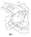
- FIG. 2is a rear perspective view of the adjustable cargo load floor according to the present teachings
- the cargo load floor 24 depicted in FIGS. 2 and 3is a generally flat, large load surface 50 , despite and relative to the various grooves and recessions in the surface 50 .
- the surface 50is not inclined relative to level ground 78 upon which the vehicle 10 may rest, thus cargo, be it cardboard boxes, bags of groceries, sports equipment, suitcases, etc. will not slide or shift in transit, as it otherwise would if such cargo were on an inclined surface. Stated another way, the surface 50 is parallel to the ground 78 .
- the flat load surface 50has various grooves 52 or recessions to capture any water or other liquids, mud, particles of dirt, dust, etc. that may result from items transported on the cargo load floor 24 .
- the cargo container 34 of the cargo bin 36exhibits a front edge 68 that has two levels.
- the upper edge 70 and lower edge 72are at such different heights or levels so that a user may place his or her hand within a cavity formed by the lower edge 72 of the cargo container 34 and the front edge 74 of the cargo load floor 24 .
Landscapes
- Engineering & Computer Science (AREA)
- Mechanical Engineering (AREA)
- Body Structure For Vehicles (AREA)
Abstract
Description
Claims (20)
Priority Applications (1)
| Application Number | Priority Date | Filing Date | Title |
|---|---|---|---|
| US11/836,361US7503610B2 (en) | 2007-08-09 | 2007-08-09 | Adjustable vehicle cargo load floor |
Applications Claiming Priority (1)
| Application Number | Priority Date | Filing Date | Title |
|---|---|---|---|
| US11/836,361US7503610B2 (en) | 2007-08-09 | 2007-08-09 | Adjustable vehicle cargo load floor |
Publications (2)
| Publication Number | Publication Date |
|---|---|
| US20090039679A1 US20090039679A1 (en) | 2009-02-12 |
| US7503610B2true US7503610B2 (en) | 2009-03-17 |
Family
ID=40345781
Family Applications (1)
| Application Number | Title | Priority Date | Filing Date |
|---|---|---|---|
| US11/836,361ActiveUS7503610B2 (en) | 2007-08-09 | 2007-08-09 | Adjustable vehicle cargo load floor |
Country Status (1)
| Country | Link |
|---|---|
| US (1) | US7503610B2 (en) |
Cited By (21)
| Publication number | Priority date | Publication date | Assignee | Title |
|---|---|---|---|---|
| US20080145172A1 (en)* | 2006-12-18 | 2008-06-19 | Lear Corporation | Vehicle cargo retainer |
| US20090001743A1 (en)* | 2007-06-28 | 2009-01-01 | International Automotive Components Group North America, Inc. | Load bearing cover assembly having support ribs that facilitate cargo management |
| US20090218849A1 (en)* | 2008-02-29 | 2009-09-03 | Gm Global Technology Operations, Inc. | Temperature-controlled cargo storage compartment |
| US20100090502A1 (en)* | 2008-10-09 | 2010-04-15 | Gm Global Technology Operations, Inc. | Adjustable Rear Load Floor for a Hybrid Vehicle |
| US20100127032A1 (en)* | 2008-11-21 | 2010-05-27 | Schubring James D | Removable in-floor storage device |
| US20110095571A1 (en)* | 2009-10-23 | 2011-04-28 | Patrick Daniel Maguire | Cargo management system |
| US20110101721A1 (en)* | 2009-10-29 | 2011-05-05 | Mazda Motor Corporation | Trunk box structure of automobile |
| US20110248521A1 (en)* | 2010-04-07 | 2011-10-13 | Honda Motor Co. Ltd. | Cargo bin and side lining walls for automotive vehicle |
| US8678462B2 (en) | 2012-01-09 | 2014-03-25 | Ford Global Technologies, Llc | Deployable load floor |
| US9062474B2 (en) | 2013-07-19 | 2015-06-23 | Honda Motor Co., Ltd. | Vehicle cargo lid assembly having compact reversible handle |
| US9376147B2 (en) | 2014-03-07 | 2016-06-28 | Fca Us Llc | Two-stage cargo floor |
| US10960941B2 (en)* | 2018-01-10 | 2021-03-30 | Polaris Industries Inc. | Vehicle |
| USD942344S1 (en) | 2019-07-26 | 2022-02-01 | Polaris Industries Inc. | Set of vehicle components |
| US11260803B2 (en) | 2019-07-26 | 2022-03-01 | Polaris Industries Inc. | Audio system for a utility vehicle |
| US11752860B2 (en) | 2015-05-15 | 2023-09-12 | Polaris Industries Inc. | Utility vehicle |
| USD999110S1 (en) | 2021-03-30 | 2023-09-19 | Polaris Industries Inc. | Utility vehicle |
| USD1069676S1 (en) | 2021-03-30 | 2025-04-08 | Polaris Industries Inc. | Storage cover |
| US12337690B2 (en) | 2020-05-15 | 2025-06-24 | Polaris Industries Inc. | Off-road vehicle |
| US12385429B2 (en) | 2022-06-13 | 2025-08-12 | Polaris Industries Inc. | Powertrain for a utility vehicle |
| US12391199B2 (en) | 2022-11-11 | 2025-08-19 | Polaris Industries Inc. | Utility vehicle fluid containment system |
| US12409784B2 (en) | 2023-04-06 | 2025-09-09 | Ford Global Technologies, Llc | Vehicle having load floor holder |
Families Citing this family (5)
| Publication number | Priority date | Publication date | Assignee | Title |
|---|---|---|---|---|
| US8757695B2 (en)* | 2012-03-21 | 2014-06-24 | GM Global Technology Operations LLC | Flat floor cargo management system |
| US9381962B2 (en)* | 2014-09-12 | 2016-07-05 | Dur-A-Bus Coach Builders Ltd. | Passenger van |
| US10112543B1 (en)* | 2017-04-06 | 2018-10-30 | GM Global Technology Operations LLC | Load floor latches and latch assemblies, and vehicles having the same |
| DE102018206316B4 (en) | 2018-04-24 | 2021-06-24 | Audi Ag | Sealed storage compartment for a motor vehicle and motor vehicle with such a storage compartment |
| US11420565B2 (en)* | 2020-12-18 | 2022-08-23 | Ford Global Technologies, Llc | Cargo divider assembly for a vehicle |
Citations (2)
| Publication number | Priority date | Publication date | Assignee | Title |
|---|---|---|---|---|
| US5836637A (en)* | 1997-10-01 | 1998-11-17 | Chrysler Corporation | Reversible vehicle floor panel |
| US6719348B1 (en)* | 2002-10-31 | 2004-04-13 | Lear Corporation | Covering for use with a motor vehicle |
- 2007
- 2007-08-09USUS11/836,361patent/US7503610B2/enactiveActive
Patent Citations (2)
| Publication number | Priority date | Publication date | Assignee | Title |
|---|---|---|---|---|
| US5836637A (en)* | 1997-10-01 | 1998-11-17 | Chrysler Corporation | Reversible vehicle floor panel |
| US6719348B1 (en)* | 2002-10-31 | 2004-04-13 | Lear Corporation | Covering for use with a motor vehicle |
Cited By (30)
| Publication number | Priority date | Publication date | Assignee | Title |
|---|---|---|---|---|
| US20080145172A1 (en)* | 2006-12-18 | 2008-06-19 | Lear Corporation | Vehicle cargo retainer |
| US20090001743A1 (en)* | 2007-06-28 | 2009-01-01 | International Automotive Components Group North America, Inc. | Load bearing cover assembly having support ribs that facilitate cargo management |
| US20090218849A1 (en)* | 2008-02-29 | 2009-09-03 | Gm Global Technology Operations, Inc. | Temperature-controlled cargo storage compartment |
| US20100090502A1 (en)* | 2008-10-09 | 2010-04-15 | Gm Global Technology Operations, Inc. | Adjustable Rear Load Floor for a Hybrid Vehicle |
| US7748775B2 (en)* | 2008-10-09 | 2010-07-06 | Gm Global Technology Operations, Inc. | Adjustable rear load floor for a hybrid vehicle |
| US8231164B2 (en)* | 2008-11-21 | 2012-07-31 | Chrysler Group Llc | Removable in-floor storage device |
| US20100127032A1 (en)* | 2008-11-21 | 2010-05-27 | Schubring James D | Removable in-floor storage device |
| US20110095571A1 (en)* | 2009-10-23 | 2011-04-28 | Patrick Daniel Maguire | Cargo management system |
| US8128146B2 (en)* | 2009-10-29 | 2012-03-06 | Mazda Motor Corporation | Trunk box structure of automobile |
| US20110101721A1 (en)* | 2009-10-29 | 2011-05-05 | Mazda Motor Corporation | Trunk box structure of automobile |
| US20110248521A1 (en)* | 2010-04-07 | 2011-10-13 | Honda Motor Co. Ltd. | Cargo bin and side lining walls for automotive vehicle |
| US8328264B2 (en)* | 2010-04-07 | 2012-12-11 | Honda Motor Co., Ltd. | Cargo bin and side lining walls for automotive vehicle |
| US8678462B2 (en) | 2012-01-09 | 2014-03-25 | Ford Global Technologies, Llc | Deployable load floor |
| US9062474B2 (en) | 2013-07-19 | 2015-06-23 | Honda Motor Co., Ltd. | Vehicle cargo lid assembly having compact reversible handle |
| US9376147B2 (en) | 2014-03-07 | 2016-06-28 | Fca Us Llc | Two-stage cargo floor |
| CN106103192B (en)* | 2014-03-07 | 2019-04-16 | Fca美国有限责任公司 | Two stages cargo floor |
| US11752860B2 (en) | 2015-05-15 | 2023-09-12 | Polaris Industries Inc. | Utility vehicle |
| US10960941B2 (en)* | 2018-01-10 | 2021-03-30 | Polaris Industries Inc. | Vehicle |
| US12258077B2 (en) | 2018-01-10 | 2025-03-25 | Polaris Industries Inc. | Vehicle |
| USD942344S1 (en) | 2019-07-26 | 2022-02-01 | Polaris Industries Inc. | Set of vehicle components |
| US11260803B2 (en) | 2019-07-26 | 2022-03-01 | Polaris Industries Inc. | Audio system for a utility vehicle |
| USD962664S1 (en) | 2019-07-26 | 2022-09-06 | Polaris Industries Inc. | Vehicle seats |
| US11926265B2 (en) | 2019-07-26 | 2024-03-12 | Polaris Industries Inc. | Audio system for a utility vehicle |
| US12337690B2 (en) | 2020-05-15 | 2025-06-24 | Polaris Industries Inc. | Off-road vehicle |
| USD999110S1 (en) | 2021-03-30 | 2023-09-19 | Polaris Industries Inc. | Utility vehicle |
| USD1069676S1 (en) | 2021-03-30 | 2025-04-08 | Polaris Industries Inc. | Storage cover |
| USD1088998S1 (en) | 2021-03-30 | 2025-08-19 | Polaris Industries Inc. | Hood for a utility vehicle |
| US12385429B2 (en) | 2022-06-13 | 2025-08-12 | Polaris Industries Inc. | Powertrain for a utility vehicle |
| US12391199B2 (en) | 2022-11-11 | 2025-08-19 | Polaris Industries Inc. | Utility vehicle fluid containment system |
| US12409784B2 (en) | 2023-04-06 | 2025-09-09 | Ford Global Technologies, Llc | Vehicle having load floor holder |
Also Published As
| Publication number | Publication date |
|---|---|
| US20090039679A1 (en) | 2009-02-12 |
Similar Documents
| Publication | Publication Date | Title |
|---|---|---|
| US7503610B2 (en) | Adjustable vehicle cargo load floor | |
| EP1121273B1 (en) | Vehicle cargo compartment liner | |
| US7156439B2 (en) | Automotive wet trunk storage compartment with drain | |
| US7281742B2 (en) | Vehicle compartment divider | |
| US8128146B2 (en) | Trunk box structure of automobile | |
| US5094375A (en) | Tray combinations | |
| US8573671B2 (en) | Toolbox system for vehicles having flared fenders | |
| US4718584A (en) | Automotive accessory for hatchback automobiles and station wagons | |
| GB2313816A (en) | Portable multi-position vehicle storage unit | |
| US20040105744A1 (en) | Moveable load floor convenience center in automotive applications | |
| US20060261111A1 (en) | Modular cargo carrier assembly | |
| US20090102219A1 (en) | Integrated bed separator and trunk lid | |
| US6196612B1 (en) | Storable exterior seat for a vehicle | |
| US6732895B2 (en) | Integrated storage apparatus for vehicle cargo compartments | |
| CN112693400B (en) | Reconfigurable storage assembly for a vehicle | |
| US5372396A (en) | Invertible cargo bed liner | |
| US20040134946A1 (en) | Vehicle seat cargo storage apparatus | |
| US20020000456A1 (en) | Arrangement for transporting objects in a motor vehicle | |
| US11951949B2 (en) | Collapsible cargo organizer | |
| EP0893307B1 (en) | Receptacle for use in vehicle luggage space | |
| US20240416841A1 (en) | Adjustable load floor system for a vehicle | |
| US20160052461A1 (en) | Stor-all vehicle storage compartment | |
| US20250058715A1 (en) | Cargo Access Apparatus for Truck Beds | |
| US20060163913A1 (en) | Removable quarter panels for open-air style vehicles | |
| FR3150746A1 (en) | Center console of a motor vehicle. |
Legal Events
| Date | Code | Title | Description |
|---|---|---|---|
| AS | Assignment | Owner name:DAIMLERCHRYSLER COMPANY LLC, MICHIGAN Free format text:ASSIGNMENT OF ASSIGNORS INTEREST;ASSIGNORS:KARAGITZ, WILLIAM A.;BITTINGER, D. SCOTT;WILLIAMS, SHAWN R.;REEL/FRAME:019807/0569 Effective date:20070803 | |
| AS | Assignment | Owner name:WILMINGTON TRUST COMPANY, DELAWARE Free format text:GRANT OF SECURITY INTEREST IN PATENT RIGHTS - FIRST PRIORITY;ASSIGNOR:CHRYSLER LLC;REEL/FRAME:020507/0166 Effective date:20070803 Owner name:WILMINGTON TRUST COMPANY, DELAWARE Free format text:GRANT OF SECURITY INTEREST IN PATENT RIGHTS - SECOND PRIORITY;ASSIGNOR:CHRYSLER LLC;REEL/FRAME:020507/0206 Effective date:20070803 Owner name:WILMINGTON TRUST COMPANY,DELAWARE Free format text:GRANT OF SECURITY INTEREST IN PATENT RIGHTS - FIRST PRIORITY;ASSIGNOR:CHRYSLER LLC;REEL/FRAME:020507/0166 Effective date:20070803 Owner name:WILMINGTON TRUST COMPANY,DELAWARE Free format text:GRANT OF SECURITY INTEREST IN PATENT RIGHTS - SECOND PRIORITY;ASSIGNOR:CHRYSLER LLC;REEL/FRAME:020507/0206 Effective date:20070803 | |
| AS | Assignment | Owner name:CHRYSLER LLC, MICHIGAN Free format text:CHANGE OF NAME;ASSIGNOR:DAIMLERCHRYSLER COMPANY LLC;REEL/FRAME:021775/0814 Effective date:20070724 | |
| AS | Assignment | Owner name:US DEPARTMENT OF THE TREASURY, DISTRICT OF COLUMBI Free format text:GRANT OF SECURITY INTEREST IN PATENT RIGHTS - THIR;ASSIGNOR:CHRYSLER LLC;REEL/FRAME:022259/0188 Effective date:20090102 Owner name:US DEPARTMENT OF THE TREASURY,DISTRICT OF COLUMBIA Free format text:GRANT OF SECURITY INTEREST IN PATENT RIGHTS - THIR;ASSIGNOR:CHRYSLER LLC;REEL/FRAME:022259/0188 Effective date:20090102 | |
| STCF | Information on status: patent grant | Free format text:PATENTED CASE | |
| AS | Assignment | Owner name:CHRYSLER LLC, MICHIGAN Free format text:RELEASE BY SECURED PARTY;ASSIGNOR:US DEPARTMENT OF THE TREASURY;REEL/FRAME:022902/0164 Effective date:20090608 Owner name:CHRYSLER LLC,MICHIGAN Free format text:RELEASE BY SECURED PARTY;ASSIGNOR:US DEPARTMENT OF THE TREASURY;REEL/FRAME:022902/0164 Effective date:20090608 | |
| AS | Assignment | Owner name:CHRYSLER LLC, MICHIGAN Free format text:RELEASE OF SECURITY INTEREST IN PATENT RIGHTS - FIRST PRIORITY;ASSIGNOR:WILMINGTON TRUST COMPANY;REEL/FRAME:022910/0498 Effective date:20090604 Owner name:CHRYSLER LLC, MICHIGAN Free format text:RELEASE OF SECURITY INTEREST IN PATENT RIGHTS - SECOND PRIORITY;ASSIGNOR:WILMINGTON TRUST COMPANY;REEL/FRAME:022910/0740 Effective date:20090604 Owner name:NEW CARCO ACQUISITION LLC, MICHIGAN Free format text:ASSIGNMENT OF ASSIGNORS INTEREST;ASSIGNOR:CHRYSLER LLC;REEL/FRAME:022915/0001 Effective date:20090610 Owner name:THE UNITED STATES DEPARTMENT OF THE TREASURY, DIST Free format text:SECURITY AGREEMENT;ASSIGNOR:NEW CARCO ACQUISITION LLC;REEL/FRAME:022915/0489 Effective date:20090610 Owner name:CHRYSLER LLC,MICHIGAN Free format text:RELEASE OF SECURITY INTEREST IN PATENT RIGHTS - FIRST PRIORITY;ASSIGNOR:WILMINGTON TRUST COMPANY;REEL/FRAME:022910/0498 Effective date:20090604 Owner name:CHRYSLER LLC,MICHIGAN Free format text:RELEASE OF SECURITY INTEREST IN PATENT RIGHTS - SECOND PRIORITY;ASSIGNOR:WILMINGTON TRUST COMPANY;REEL/FRAME:022910/0740 Effective date:20090604 Owner name:NEW CARCO ACQUISITION LLC,MICHIGAN Free format text:ASSIGNMENT OF ASSIGNORS INTEREST;ASSIGNOR:CHRYSLER LLC;REEL/FRAME:022915/0001 Effective date:20090610 Owner name:THE UNITED STATES DEPARTMENT OF THE TREASURY,DISTR Free format text:SECURITY AGREEMENT;ASSIGNOR:NEW CARCO ACQUISITION LLC;REEL/FRAME:022915/0489 Effective date:20090610 | |
| AS | Assignment | Owner name:CHRYSLER GROUP LLC, MICHIGAN Free format text:CHANGE OF NAME;ASSIGNOR:NEW CARCO ACQUISITION LLC;REEL/FRAME:022919/0126 Effective date:20090610 Owner name:CHRYSLER GROUP LLC,MICHIGAN Free format text:CHANGE OF NAME;ASSIGNOR:NEW CARCO ACQUISITION LLC;REEL/FRAME:022919/0126 Effective date:20090610 | |
| AS | Assignment | Owner name:CHRYSLER GROUP GLOBAL ELECTRIC MOTORCARS LLC, NORT Free format text:RELEASE BY SECURED PARTY;ASSIGNOR:THE UNITED STATES DEPARTMENT OF THE TREASURY;REEL/FRAME:026343/0298 Effective date:20110524 Owner name:CHRYSLER GROUP LLC, MICHIGAN Free format text:RELEASE BY SECURED PARTY;ASSIGNOR:THE UNITED STATES DEPARTMENT OF THE TREASURY;REEL/FRAME:026343/0298 Effective date:20110524 | |
| AS | Assignment | Owner name:CITIBANK, N.A., NEW YORK Free format text:SECURITY AGREEMENT;ASSIGNOR:CHRYSLER GROUP LLC;REEL/FRAME:026404/0123 Effective date:20110524 | |
| AS | Assignment | Owner name:CITIBANK, N.A., NEW YORK Free format text:SECURITY AGREEMENT;ASSIGNOR:CHRYSLER GROUP LLC;REEL/FRAME:026435/0652 Effective date:20110524 | |
| FPAY | Fee payment | Year of fee payment:4 | |
| AS | Assignment | Owner name:JPMORGAN CHASE BANK, N.A., ILLINOIS Free format text:SECURITY AGREEMENT;ASSIGNOR:CHRYSLER GROUP LLC;REEL/FRAME:032384/0640 Effective date:20140207 | |
| AS | Assignment | Owner name:FCA US LLC, MICHIGAN Free format text:CHANGE OF NAME;ASSIGNOR:CHRYSLER GROUP LLC;REEL/FRAME:035553/0356 Effective date:20141203 | |
| AS | Assignment | Owner name:FCA US LLC, FORMERLY KNOWN AS CHRYSLER GROUP LLC, Free format text:RELEASE OF SECURITY INTEREST RELEASING SECOND-LIEN SECURITY INTEREST PREVIOUSLY RECORDED AT REEL 026426 AND FRAME 0644, REEL 026435 AND FRAME 0652, AND REEL 032384 AND FRAME 0591;ASSIGNOR:CITIBANK, N.A.;REEL/FRAME:037784/0001 Effective date:20151221 | |
| FPAY | Fee payment | Year of fee payment:8 | |
| AS | Assignment | Owner name:FCA US LLC (FORMERLY KNOWN AS CHRYSLER GROUP LLC), Free format text:RELEASE BY SECURED PARTY;ASSIGNOR:CITIBANK, N.A.;REEL/FRAME:042885/0255 Effective date:20170224 | |
| AS | Assignment | Owner name:FCA US LLC (FORMERLY KNOWN AS CHRYSLER GROUP LLC), Free format text:RELEASE BY SECURED PARTY;ASSIGNOR:JPMORGAN CHASE BANK, N.A.;REEL/FRAME:048177/0356 Effective date:20181113 | |
| MAFP | Maintenance fee payment | Free format text:PAYMENT OF MAINTENANCE FEE, 12TH YEAR, LARGE ENTITY (ORIGINAL EVENT CODE: M1553); ENTITY STATUS OF PATENT OWNER: LARGE ENTITY Year of fee payment:12 |