US7503536B2 - Universal projector mount - Google Patents
Universal projector mountDownload PDFInfo
- Publication number
- US7503536B2 US7503536B2US11/040,811US4081105AUS7503536B2US 7503536 B2US7503536 B2US 7503536B2US 4081105 AUS4081105 AUS 4081105AUS 7503536 B2US7503536 B2US 7503536B2
- Authority
- US
- United States
- Prior art keywords
- mount
- central member
- projector
- arm body
- arm
- Prior art date
- Legal status (The legal status is an assumption and is not a legal conclusion. Google has not performed a legal analysis and makes no representation as to the accuracy of the status listed.)
- Active, expires
Links
Images


Classifications
- F—MECHANICAL ENGINEERING; LIGHTING; HEATING; WEAPONS; BLASTING
- F16—ENGINEERING ELEMENTS AND UNITS; GENERAL MEASURES FOR PRODUCING AND MAINTAINING EFFECTIVE FUNCTIONING OF MACHINES OR INSTALLATIONS; THERMAL INSULATION IN GENERAL
- F16M—FRAMES, CASINGS OR BEDS OF ENGINES, MACHINES OR APPARATUS, NOT SPECIFIC TO ENGINES, MACHINES OR APPARATUS PROVIDED FOR ELSEWHERE; STANDS; SUPPORTS
- F16M11/00—Stands or trestles as supports for apparatus or articles placed thereon ; Stands for scientific apparatus such as gravitational force meters
- F16M11/02—Heads
- F16M11/04—Means for attachment of apparatus; Means allowing adjustment of the apparatus relatively to the stand
- F16M11/043—Allowing translations
- F—MECHANICAL ENGINEERING; LIGHTING; HEATING; WEAPONS; BLASTING
- F16—ENGINEERING ELEMENTS AND UNITS; GENERAL MEASURES FOR PRODUCING AND MAINTAINING EFFECTIVE FUNCTIONING OF MACHINES OR INSTALLATIONS; THERMAL INSULATION IN GENERAL
- F16M—FRAMES, CASINGS OR BEDS OF ENGINES, MACHINES OR APPARATUS, NOT SPECIFIC TO ENGINES, MACHINES OR APPARATUS PROVIDED FOR ELSEWHERE; STANDS; SUPPORTS
- F16M11/00—Stands or trestles as supports for apparatus or articles placed thereon ; Stands for scientific apparatus such as gravitational force meters
- F16M11/02—Heads
- F16M11/04—Means for attachment of apparatus; Means allowing adjustment of the apparatus relatively to the stand
- F16M11/06—Means for attachment of apparatus; Means allowing adjustment of the apparatus relatively to the stand allowing pivoting
- F16M11/12—Means for attachment of apparatus; Means allowing adjustment of the apparatus relatively to the stand allowing pivoting in more than one direction
Definitions
- the present inventionrelates generally to mounts for projectors. More particularly, the present invention relates to a universal mount for a projector.
- Visual projection systemsare commonly used for entertainment and displaying, and presenting visual information to groups of people.
- Such visual projection systemstypically include a projector unit and a projection screen.
- the projector unitIn spaces such as classrooms, conference rooms, and public assembly halls, where the space is often used for presentations, and in home entertainment rooms, it is common that the projector unit be installed as a more or less permanent fixture in the space. Often, the projector will be suspended from an overhead structure, such as a building floor/ceiling assembly or roof, in order to give the projector an unobstructed projection path and to protect it from damage by inadvertent contact. It is generally desirable that the mount be adjustable over a wide range of positions to enable proper aiming and focusing of the projector.
- Projectorsparticularly LCD, CRT, and DRP projectors designed for frequent use in a setting such as described above are quite expensive.
- the spaces where the projector is installedmay be left unsecured for periods of time or left unattended. Consequently, a problem is that projector units are attractive targets for theft, vandalism and other tampering.
- mountable projectorsThere are many different makes and models of mountable projectors commercially available today. There is no single standard for mounting attachments in the industry, and consequently, the mounting attachment fixture configurations differ widely between manufacturers. A consequent problem with available mounting devices to date has been that mounts are not generally interchangeable between projector makes, and therefore, mounts must be made in a large variety of separate configurations. The industry would benefit from a single universal projector mount that can be fitted to mount projectors of a variety of different makes and models.
- the present inventionis directed to a universal projector mount that meets the need of the industry for a single universal projector mount that can be fitted to mount projectors of a variety of different makes and models.
- a plurality of adjustable armsare operably coupled with an interface plate that is in turn attached to a standard projector mount on the fixed structure from which the projector will be hung.
- the armsare adjustable radially and longitudinally to virtually any position so as to accommodate various fastener or fastener receiving locations on different makes and models of projectors.
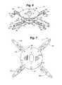
- FIG. 1is a perspective view of a universal projector mount according to an embodiment of the present invention
- FIG. 2is an exploded view of the universal projector mount of FIG. 1 ;
- FIG. 3is a perspective view of the universal projector mount of FIG. 1 with an overhead projector mount attached thereto;
- FIG. 4is a perspective view of the universal projector mount of FIG. 1 with the arms positioned in an extended position;
- FIG. 5is another perspective view of the universal projector mount of FIG. 1 ;
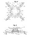
- FIG. 6is a perspective view of another universal projector mount according to the present invention.
- FIG. 7is a rear elevation view of the universal projector mount of FIG. 6 ;
- FIG. 8is a front elevation view of the universal projector mount of FIG. 6 ;
- FIG. 9is a top plan view of the universal projector mount of FIG. 6 ;
- FIG. 10is a side elevation view of the universal projector mount of FIG. 6 ;
- FIG. 11is a perspective view of the universal projector mount of FIG. 6 with parts removed for clarity;
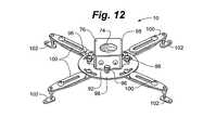
- FIG. 12is a rear elevation view of the universal projector mount of FIG. 6 with parts removed.
- the universal projector mount 10 of the present inventiongenerally includes a mount interface 12 and arms 14 .
- Mount interface 12generally includes central member 16 having studs 18 for detachably receiving an overhead projector mount 20 .
- Overhead projector mount 20is known in the art and more fully described in co-pending U.S. Utility patent No. 7,156,359, commonly owned by the owners of the present invention and hereby incorporated herein in its entirety by reference.
- Central member 16has a recessed portion 22 recessed from peripheral margin 24 .
- Elongate slots 26are defined in recessed portion 22 and arranged just inside peripheral margin 24 .
- Elongate slots 26include curved slots 27 at the corners and generally straight slots 27 a along the sides.
- Central aperture 28may be provided if desired to lighten the structure.
- Each arm 14includes elongate beam portion 30 and foot 32 .
- Elongate beam portion 30may have a generally u-shaped cross section with a web 34 , sidewalls 36 , and end wall 37 .
- Web 34defines one or more slots 38 along its longitudinal axis.
- End wall 37has an aperture 40 defined therein, which may be threaded for receiving a fastener 42 .
- Foot 32may be generally L-shaped, with interface flange portion 44 and projector attachment ear 46 .
- Interface flange portion 44defines slot 48 , through which fastener 42 is received to secure foot 32 to beam portion 30 .
- Projector attachment ear 46has an aperture 49 defined therein for receiving a fastener 50 to attach foot 32 to a projector 52 .
- Each arm 14is fastened to central member 16 with a threaded fastener 54 extending through one of elongate slots 26 in central member 16 and slot 38 into threaded nut 56 .
- each fastener 54is loosened, enabling fastener 54 to slide within the elongate slot 26 through which it extends. Further, slot 38 enables arm 14 to slide radially and rotate relative to central member 16 .
- Each arm 14may be positioned so that aperture 49 of attachment ear 46 corresponds with an attachment fixture on projector 52 .
- fastener 54is tightened to secure arm 14 in the desired position and foot 32 is fastened to the projector 52 with a fastener 50 through aperture 49 .
- each fastener 42may be loosened, enabling foot 32 to slide vertically in order to adjust the spacing of central member 16 from projector 52 . Once in the desired position, fastener 42 may be tightened to secure foot 32 in position.
- the overhead projector mount 20may be attached to central member 16 .
- mount 10has notches 58 corresponding to studs 18 . Each stud 18 is received in a notch 58 and the overhead projector mount is secured in position with knurled nut 60 .
- each arm 14may be adjusted so that aperture 49 may be positioned in virtually any position inside a radius defined by the length of arm 14 around fastener 54 .
- each arm 14may be attached to central member 16 with the fastener 54 through any of elongate slots 26 .
- mount 10is adjustable to a virtually unlimited number of configurations to correspond with nearly any geometric arrangement of fastener receiving locations on a given projector 52 .
- any other number of arms 14from two to eight or more may be used within the scope of the present invention.
- the universal projector mount 10As depicted in FIGS. 6-12 , generally includes base plate 66 , universal joint portion 68 , and mount interface 70 .
- Base plate 66may be substantially flat as depicted here or differently shaped to adapt to mounting to a variety of surfaces.
- Base plate 66has a plurality of apertures 72 at the periphery thereof adapted to accept fasteners for securing base plate 66 to a surface of a supporting structure.
- Base plate 66is operably attached to universal joint portion 68 .
- base plate 66may be connected to universal joint portion 68 by large threaded mount 74 .
- the term base plate 66is defined for the purposes of this application to encompass portions of overhead projector mount 20 used for securing overhead projector mount 20 to a structure.
- Base plate 66may include structures such as struts and tubes that may be used to support universal projector mount at a distance from a building structure.
- universal joint portion 68generally includes base plate yoke 76 , cross portion 78 , and mount interface yoke 80 .
- Base plate yoke 76is attached to cross portion 78 at pivot 82 to allow rotation of base plate yoke 76 and, consequently, base plate 66 about a first axis.
- Base plate yoke 76defines curved slot 84 through which fastener 86 may be inserted and through which fastener 86 may be tightened to secure base plate yoke 76 rotationally to cross portion 78 thus locking base plate yoke 76 in position relative to cross portion 78 .
- Mounting interface yoke 80is pivotably secured to cross portion 78 at pivot 88 .
- Mounting interface yoke 80may be rotationally secured to cross portion 78 relative to pivot 88 by locking fastener 90 thus locking mount interface yoke 80 to cross portion 78 in a specific orientation about a second axis which is substantially perpendicular to the first axis.
- mount interface yoke 80further includes attachment plate 92 .
- Attachment plate 92defines notches 94 which are adapted to interface with knurled nut 96 to secure attachment plate 92 and thus mount interface yoke 80 to mount interface 70 .
- the term base plate 66is defined for the purposes of this application to encompass portions of overhead projector mount 20 .
- Mount interface 70generally includes central member 98 , arms 100 , and attachment ears 102 .
- Central member 98supports studs 104 and is pierced by circumferential slots 106 near its periphery. Studs 104 are located to align with notches 94 of attachment plate 92 . Thus studs 104 can receive knurled nut 96 to secure attachment plate 92 to central member 98 .
- Circumferential slots 106may number 4, but his number should not be considered limiting.
- Arms 100are secured to central member 98 by arm fastener 108 .
- Arm fastener 108may be, for example, a screw or bolt. Arm fastener 108 may be secured anywhere along the length of circumferential slots 106 .
- Arms 100include first section 110 , and second section 112 .
- First section 110 and second section 112are telescopically slidable relative to one another so that the length of arms 100 may be adjusted.
- second section 112may include arm slot 114 adapted to slideably engage with fastener 116 which is secured to first section 110 .
- Fastener 116may be tightened to secure first section 110 to second section 112 at a desired degree of telescopic elongation to fix the length of arm 100 .
- Attachment ears 102are supported at distal end 118 of arms 100 via adjustment stud 120 .
- Adjustment stud 120may be screwed into threaded aperture 122 at the distal end 118 of arm 100 .
- Lock nut 124may be utilized on adjustment stud 120 to secure attachment ears 102 at a desired orientation.
- Apertures 126pierce attachment ears 102 .
- Apertures 126are adapted to receive fasteners to secure attachment ears 102 to a projector (not shown).
- base plate 66may be secured to any convenient surface to which it is desired to secure universal projector mount 10 .
- universal joint portion 68may be secured to base plate 66 .
- Mount interface 70may be secured to projector or any other device that it is desired to mount and then mount interface 70 is secured to universal joint portion 68 .
- Universal joint portion 68may then be adjusted to align the projector to aim it as desired.
- Mount interface 70may be secured to universal joint portion 68 via attachment plate 92 .
- Attachment plate 92is positioned so that notches 94 engage to studs 104 and knurled nuts 96 may then be tightened to secure mount interface 70 to universal joint portion 68 .
- Universal joint portion 68may be moved to a plurality of positions by adjusting base plate yoke 76 relative to cross portion 78 and mount interface yoke 80 relative to cross portion 78 . Once a desired position is achieved, fastener 86 and locking fastener 90 may be tightened to secure universal joint portion 58 in a desired orientation.
- arms 100When attaching a projector to mount interface 70 , arms 100 may be adjusted positionally within circumferential slots 106 to any desired location. In addition, arms 100 may be rotated relative to circumferential slots 106 to any desired angle. First section 110 and second section 112 may be adjusted telescopically relative to each other to adjust arm 100 to any necessary length. Attachment ears 102 may be adjusted, both angularly relative to the distal end 118 of arms 100 , and in a degree of offset between the peripheral ends of arms 100 and attachment ears 102 by screwing adjustment stud 120 into or out of threaded aperture 122 . Once a desired adjustment is achieved, lock nut 124 may be tightened on adjustment stud 120 to lock adjustment ears 102 relative to the peripheral end of arms 100 .
- apertures 126 on attachment ears 102may be adjusted to align with virtually any arrangement of attachment positions on any projector that may be presented.
Landscapes
- Engineering & Computer Science (AREA)
- General Engineering & Computer Science (AREA)
- Mechanical Engineering (AREA)
- Projection Apparatus (AREA)
Abstract
Description
Claims (8)
Priority Applications (6)
| Application Number | Priority Date | Filing Date | Title |
|---|---|---|---|
| US11/040,811US7503536B2 (en) | 2004-01-23 | 2005-01-21 | Universal projector mount |
| PCT/US2005/002179WO2005069992A2 (en) | 2004-01-23 | 2005-01-24 | Universal projector mount |
| AU2005207024AAU2005207024A1 (en) | 2004-01-23 | 2005-01-24 | Universal projector mount |
| CA002553819ACA2553819A1 (en) | 2004-01-23 | 2005-01-24 | Universal projector mount |
| JP2006551364AJP2008503761A (en) | 2004-01-23 | 2005-01-24 | Universal projector mounting device |
| EP05711907AEP1751464A2 (en) | 2004-01-23 | 2005-01-24 | Universal projector mount |
Applications Claiming Priority (3)
| Application Number | Priority Date | Filing Date | Title |
|---|---|---|---|
| US53863404P | 2004-01-23 | 2004-01-23 | |
| US63771004P | 2004-12-21 | 2004-12-21 | |
| US11/040,811US7503536B2 (en) | 2004-01-23 | 2005-01-21 | Universal projector mount |
Publications (2)
| Publication Number | Publication Date |
|---|---|
| US20050161575A1 US20050161575A1 (en) | 2005-07-28 |
| US7503536B2true US7503536B2 (en) | 2009-03-17 |
Family
ID=34799413
Family Applications (1)
| Application Number | Title | Priority Date | Filing Date |
|---|---|---|---|
| US11/040,811Active2026-02-19US7503536B2 (en) | 2004-01-23 | 2005-01-21 | Universal projector mount |
Country Status (6)
| Country | Link |
|---|---|
| US (1) | US7503536B2 (en) |
| EP (1) | EP1751464A2 (en) |
| JP (1) | JP2008503761A (en) |
| AU (1) | AU2005207024A1 (en) |
| CA (1) | CA2553819A1 (en) |
| WO (1) | WO2005069992A2 (en) |
Cited By (29)
| Publication number | Priority date | Publication date | Assignee | Title |
|---|---|---|---|---|
| US20080061200A1 (en)* | 2006-09-13 | 2008-03-13 | Bouissiere Michael F | Mount with magnetic attachment and automatic safety latching |
| US20090108150A1 (en)* | 2004-12-27 | 2009-04-30 | Premier Mounts | Mount and Leveling System |
| US20090294619A1 (en)* | 2008-05-29 | 2009-12-03 | Mike David | Projector mount with phillips screw driver angle adjustment |
| US20090316118A1 (en)* | 2008-06-12 | 2009-12-24 | Jay Dittmer | Universal projector interface with sustainable alignment |
| USD611084S1 (en)* | 2008-12-09 | 2010-03-02 | Peerless Industries, Inc. | Projector mounting device |
| US20100088963A1 (en)* | 2006-12-13 | 2010-04-15 | Faac S.P.A. | Ceiling driving unit for moving doors |
| USD616011S1 (en)* | 2008-06-12 | 2010-05-18 | Milestone Av Technologies Llc | Universal projector mount |
| US20100176264A1 (en)* | 2009-01-13 | 2010-07-15 | Nokia Corporation | Adjustable device mount |
| USD624578S1 (en) | 2009-04-14 | 2010-09-28 | Milestone Av Technologies Llc | Universal projector mount |
| USD633548S1 (en)* | 2010-07-27 | 2011-03-01 | Ming-Hsien Huang | Projector holder |
| US20110199752A1 (en)* | 2008-09-25 | 2011-08-18 | Koninklijke Philips Electronics N.V. | Mount for mounting an electrical appliance, stand comprising the mount and toolkit |
| US20130075544A1 (en)* | 2011-09-26 | 2013-03-28 | Li-Wei Liu | Supporting apparatus |
| USD682913S1 (en)* | 2011-09-27 | 2013-05-21 | Peerless Industries, Inc. | Projector mount for use with audio/visual devices or the like |
| US20130264434A1 (en)* | 2012-04-06 | 2013-10-10 | Seiko Epson Corporation | Ceiling hanger |
| US20140077053A1 (en)* | 2012-09-17 | 2014-03-20 | Delta Electronics, Inc. | Projector mount |
| US8910916B2 (en) | 2011-10-21 | 2014-12-16 | Joseph Karl Rafalik | Security mounting pole apparatus and method of use |
| US9052057B2 (en) | 2012-10-02 | 2015-06-09 | Mw Products Llc | Flexible mount apparatus and system |
| US20150323124A1 (en)* | 2014-05-08 | 2015-11-12 | Dish Network L.L.C | Lattice Mounting Device |
| WO2016132048A1 (en) | 2015-02-19 | 2016-08-25 | 5V | Securing device for an appliance of the video projector type |
| US20190250661A1 (en)* | 2018-02-12 | 2019-08-15 | Charles Edward Shirley | Universal vesa adaptor |
| US20190335071A1 (en)* | 2018-04-27 | 2019-10-31 | Skope, LLC | Adjustable smartphone assembly for an optical device eyepiece |
| US11402057B1 (en)* | 2021-03-18 | 2022-08-02 | Oxti Corporation | Securely mountable/dismountable electronic equipment support stand |
| USD962325S1 (en)* | 2020-09-10 | 2022-08-30 | Wuxi Gleam Musical Instrument Technology Co., Ltd. | Projector support stand |
| USD963658S1 (en)* | 2018-12-17 | 2022-09-13 | CKnapp Sales, Inc. | Projection mounting device |
| US11566637B2 (en) | 2018-08-21 | 2023-01-31 | Hunter Fan Company | Ceiling fan hanger assembly |
| US11608969B2 (en)* | 2020-03-04 | 2023-03-21 | Axis Lighting Inc. | Luminaire structures |
| US11608967B2 (en) | 2020-03-04 | 2023-03-21 | Axis Lighting Inc. | Luminaire structure |
| US20230189988A1 (en)* | 2016-12-08 | 2023-06-22 | B Lam Limited | Anti-vibration device for sound equipment |
| US12241615B1 (en) | 2017-06-19 | 2025-03-04 | Axis Lighting Inc. | Luminaire structure |
Families Citing this family (23)
| Publication number | Priority date | Publication date | Assignee | Title |
|---|---|---|---|---|
| US20090050760A1 (en)* | 2004-07-30 | 2009-02-26 | Atdec Pty Limited | Adjustable mounting for flat panel displays |
| TWI240054B (en)* | 2004-08-18 | 2005-09-21 | Benq Corp | Structure for hanging an electronic device |
| TWM292662U (en)* | 2005-12-27 | 2006-06-21 | Ming-Shian Huang | Ceiling hanger |
| US7922139B2 (en)* | 2006-05-05 | 2011-04-12 | Milestone Av Technologies Llc | Adjustable projector mount |
| USD570894S1 (en)* | 2006-05-05 | 2008-06-10 | Csav, Inc. | Projector mount adjustment assembly |
| GB2443267B (en)* | 2006-10-28 | 2010-01-27 | Wall Off | Visual display unit mount |
| TWI501020B (en)* | 2008-10-02 | 2015-09-21 | Peerless Ind Inc | Mounting system |
| USD609552S1 (en) | 2008-12-09 | 2010-02-09 | Peerless Industries, Inc. | Mount portion |
| GB2470729B (en) | 2009-06-01 | 2013-01-02 | Promethean Ltd | Projector mount |
| USD669758S1 (en)* | 2010-11-09 | 2012-10-30 | E-Business International, Inc. | Hub enclosure assembly for electronic device |
| TWI421621B (en)* | 2011-01-27 | 2014-01-01 | Delta Electronics Inc | Projecting apparatus having adjusting function |
| CN102736388B (en)* | 2011-04-08 | 2015-01-14 | 中强光电股份有限公司 | Projector hanger device |
| CN102778809B (en)* | 2012-08-16 | 2014-11-05 | 吴槐 | Adjusting seat frame of projector |
| US9395033B2 (en) | 2013-03-13 | 2016-07-19 | Ergotron, Inc. | Projector mount system and method |
| US9410658B2 (en)* | 2013-09-05 | 2016-08-09 | Ergotron, Inc. | Projector adjustment mechanism |
| US20150157103A1 (en)* | 2013-12-09 | 2015-06-11 | Joshua Simon | Electronic device case |
| CN204083712U (en)* | 2014-06-12 | 2015-01-07 | 深圳Tcl新技术有限公司 | Television stand and panel TV set |
| EP3286481A4 (en)* | 2015-04-23 | 2019-01-09 | Milestone AV Technologies LLC | SHORT-RANGE PROJECTOR SUPPORT WITH ADJUSTABLE SCREW DRIVE |
| CN105864596A (en)* | 2016-07-14 | 2016-08-17 | 奇瑞汽车股份有限公司 | Adjustable engine holding base |
| US11306865B1 (en)* | 2017-06-22 | 2022-04-19 | Russ Bassett Corporation | Quick connect having a secured position and a release position |
| USD907641S1 (en)* | 2019-08-15 | 2021-01-12 | Apple Inc. | Video device stand |
| USD918880S1 (en)* | 2020-08-04 | 2021-05-11 | Shenzhen Mengxiangyuan Fitness Development Co., Ltd. | Display mount |
| CN112460383A (en)* | 2020-10-20 | 2021-03-09 | 北京轩宇智能科技有限公司 | Base structure for equipment adjustment/replacement |
Citations (21)
| Publication number | Priority date | Publication date | Assignee | Title |
|---|---|---|---|---|
| US4964606A (en) | 1989-10-26 | 1990-10-23 | Ncr Corporation | Overhead mount for a CRT |
| US4993676A (en) | 1990-01-16 | 1991-02-19 | Fitts William E | Apparatus for supporting a television set from a ceiling |
| US5009384A (en) | 1990-06-29 | 1991-04-23 | Inter-Link Communciations Inc. | Overhead support system for TV monitors |
| US5383641A (en) | 1992-10-27 | 1995-01-24 | Peerless Industries, Inc. | Television support member security mounting assembly |
| US5490655A (en) | 1993-09-16 | 1996-02-13 | Monger Mounts, Inc. | Video/data projector and monitor ceiling/wall mount |
| US5551658A (en) | 1994-08-15 | 1996-09-03 | Chief Manufacturing, Inc. | Projector lift system |
| US5621846A (en) | 1995-05-17 | 1997-04-15 | The W. B. Marvin Manufacturing Company | Radiant electric space heater with angular adjustment support bracket |
| US5730410A (en) | 1996-06-10 | 1998-03-24 | Archambault; Marc-Antoine | Ceiling mounted displaceable support arm for suspending a device |
| US5938161A (en)* | 1996-06-14 | 1999-08-17 | Nec Corporation | Projection installing device |
| US5946404A (en) | 1995-06-01 | 1999-08-31 | Silent Witness Enterprises Ltd. | Audio/video surveillance and recording system |
| US5944896A (en) | 1997-09-24 | 1999-08-31 | Lawson Screen Products, Inc. | Adjustable support for print screens |
| US6042068A (en)* | 1997-09-04 | 2000-03-28 | Peerless Indsutries, Inc. | Low profile LCD projector mount |
| US6527238B2 (en) | 2001-01-29 | 2003-03-04 | Top I Vision Ltd | Stabilizing system for an image-producing means |
| US6708940B2 (en)* | 2000-06-13 | 2004-03-23 | Peter Ligertwood | Mounting bracket |
| USD514612S1 (en)* | 2003-08-13 | 2006-02-07 | Vogel's Holdin B.V. | Projector stand |
| US20060186301A1 (en)* | 2004-12-27 | 2006-08-24 | Premier Mounts | Mount and leveling system |
| US20070034764A1 (en)* | 2003-04-11 | 2007-02-15 | Csav, Inc. | Secure mounting system for overhead mounted projector |
| USD540367S1 (en)* | 2005-01-21 | 2007-04-10 | Csav, Inc. | Universal projector mount |
| US7317611B2 (en) | 2003-07-23 | 2008-01-08 | Chief Manufacturing Inc. | Under-cabinet mount for flat-panel displays |
| USD560669S1 (en)* | 2006-07-28 | 2008-01-29 | Omnimount Systems, Inc. | Rotatable mount for audio/visual equipment |
| US20080061200A1 (en)* | 2006-09-13 | 2008-03-13 | Bouissiere Michael F | Mount with magnetic attachment and automatic safety latching |
Family Cites Families (8)
| Publication number | Priority date | Publication date | Assignee | Title |
|---|---|---|---|---|
| JPH0732560Y2 (en)* | 1992-07-14 | 1995-07-26 | 株式会社名装 | Telescopic tube for elevators such as projectors |
| KR100210772B1 (en)* | 1995-03-31 | 1999-07-15 | 전주범 | Apparatus for controlling projection angle of 3-beam separation method |
| JPH09304833A (en)* | 1996-05-14 | 1997-11-28 | Nikon Corp | Projection projector |
| JP3669908B2 (en)* | 2000-09-04 | 2005-07-13 | 株式会社キクチ科学研究所 | Stand |
| JP2002344846A (en)* | 2001-05-18 | 2002-11-29 | Fujitsu General Ltd | Ceiling mount for projector |
| JP3947862B2 (en)* | 2001-07-11 | 2007-07-25 | Necディスプレイソリューションズ株式会社 | Ceiling mount structure and projector fixed to the ceiling mount structure |
| JP2003029340A (en)* | 2001-07-19 | 2003-01-29 | Fujitsu General Ltd | Projector suspension device |
| JP2003110966A (en)* | 2001-09-28 | 2003-04-11 | Futaba Kinzoku Kogyo Kk | Mount board for device |
- 2005
- 2005-01-21USUS11/040,811patent/US7503536B2/enactiveActive
- 2005-01-24JPJP2006551364Apatent/JP2008503761A/enactivePending
- 2005-01-24WOPCT/US2005/002179patent/WO2005069992A2/enactiveApplication Filing
- 2005-01-24AUAU2005207024Apatent/AU2005207024A1/ennot_activeAbandoned
- 2005-01-24CACA002553819Apatent/CA2553819A1/ennot_activeAbandoned
- 2005-01-24EPEP05711907Apatent/EP1751464A2/ennot_activeWithdrawn
Patent Citations (21)
| Publication number | Priority date | Publication date | Assignee | Title |
|---|---|---|---|---|
| US4964606A (en) | 1989-10-26 | 1990-10-23 | Ncr Corporation | Overhead mount for a CRT |
| US4993676A (en) | 1990-01-16 | 1991-02-19 | Fitts William E | Apparatus for supporting a television set from a ceiling |
| US5009384A (en) | 1990-06-29 | 1991-04-23 | Inter-Link Communciations Inc. | Overhead support system for TV monitors |
| US5383641A (en) | 1992-10-27 | 1995-01-24 | Peerless Industries, Inc. | Television support member security mounting assembly |
| US5490655A (en) | 1993-09-16 | 1996-02-13 | Monger Mounts, Inc. | Video/data projector and monitor ceiling/wall mount |
| US5551658A (en) | 1994-08-15 | 1996-09-03 | Chief Manufacturing, Inc. | Projector lift system |
| US5621846A (en) | 1995-05-17 | 1997-04-15 | The W. B. Marvin Manufacturing Company | Radiant electric space heater with angular adjustment support bracket |
| US5946404A (en) | 1995-06-01 | 1999-08-31 | Silent Witness Enterprises Ltd. | Audio/video surveillance and recording system |
| US5730410A (en) | 1996-06-10 | 1998-03-24 | Archambault; Marc-Antoine | Ceiling mounted displaceable support arm for suspending a device |
| US5938161A (en)* | 1996-06-14 | 1999-08-17 | Nec Corporation | Projection installing device |
| US6042068A (en)* | 1997-09-04 | 2000-03-28 | Peerless Indsutries, Inc. | Low profile LCD projector mount |
| US5944896A (en) | 1997-09-24 | 1999-08-31 | Lawson Screen Products, Inc. | Adjustable support for print screens |
| US6708940B2 (en)* | 2000-06-13 | 2004-03-23 | Peter Ligertwood | Mounting bracket |
| US6527238B2 (en) | 2001-01-29 | 2003-03-04 | Top I Vision Ltd | Stabilizing system for an image-producing means |
| US20070034764A1 (en)* | 2003-04-11 | 2007-02-15 | Csav, Inc. | Secure mounting system for overhead mounted projector |
| US7317611B2 (en) | 2003-07-23 | 2008-01-08 | Chief Manufacturing Inc. | Under-cabinet mount for flat-panel displays |
| USD514612S1 (en)* | 2003-08-13 | 2006-02-07 | Vogel's Holdin B.V. | Projector stand |
| US20060186301A1 (en)* | 2004-12-27 | 2006-08-24 | Premier Mounts | Mount and leveling system |
| USD540367S1 (en)* | 2005-01-21 | 2007-04-10 | Csav, Inc. | Universal projector mount |
| USD560669S1 (en)* | 2006-07-28 | 2008-01-29 | Omnimount Systems, Inc. | Rotatable mount for audio/visual equipment |
| US20080061200A1 (en)* | 2006-09-13 | 2008-03-13 | Bouissiere Michael F | Mount with magnetic attachment and automatic safety latching |
Non-Patent Citations (2)
| Title |
|---|
| Chief Manufacturing Inc., Full-Line Product Guide 2003, Presentation Support Solutions, Jan. 2003, 10 pages. |
| Peerless Industries, Inc., Peerless Series Projector Mount PRS-UNV issued Jan. 26, 2004 Sheet No. 0555-9821-3.* |
Cited By (41)
| Publication number | Priority date | Publication date | Assignee | Title |
|---|---|---|---|---|
| US20090108150A1 (en)* | 2004-12-27 | 2009-04-30 | Premier Mounts | Mount and Leveling System |
| US7942375B2 (en)* | 2004-12-27 | 2011-05-17 | Premier Mounts | Mount and leveling system |
| US7758001B2 (en)* | 2006-09-13 | 2010-07-20 | Premier Mounts | Mount with magnetic attachment and automatic safety latching |
| US20080061200A1 (en)* | 2006-09-13 | 2008-03-13 | Bouissiere Michael F | Mount with magnetic attachment and automatic safety latching |
| US20100242404A1 (en)* | 2006-09-13 | 2010-09-30 | Premier Mounts | Mount with magnetic attachment and automatic safety latching |
| US20100088963A1 (en)* | 2006-12-13 | 2010-04-15 | Faac S.P.A. | Ceiling driving unit for moving doors |
| US20090294619A1 (en)* | 2008-05-29 | 2009-12-03 | Mike David | Projector mount with phillips screw driver angle adjustment |
| US8033519B2 (en)* | 2008-05-29 | 2011-10-11 | Mike David | Projector mount with Phillips screw driver angle adjustment |
| USD616011S1 (en)* | 2008-06-12 | 2010-05-18 | Milestone Av Technologies Llc | Universal projector mount |
| US8519326B2 (en) | 2008-06-12 | 2013-08-27 | Milestone A V Technologies LLC | Universal projector interface having at least one arm assembly including an elongate arm member and a shiftable coupling portion with sustainable alignment |
| US20090316118A1 (en)* | 2008-06-12 | 2009-12-24 | Jay Dittmer | Universal projector interface with sustainable alignment |
| US8138469B2 (en) | 2008-06-12 | 2012-03-20 | Milestone Av Technologies Llc | Universal projector interface having at least one arm assembly including an elongate arm member and a shiftable coupling portion with sustainable alignment |
| US20110199752A1 (en)* | 2008-09-25 | 2011-08-18 | Koninklijke Philips Electronics N.V. | Mount for mounting an electrical appliance, stand comprising the mount and toolkit |
| USD611084S1 (en)* | 2008-12-09 | 2010-03-02 | Peerless Industries, Inc. | Projector mounting device |
| US20100176264A1 (en)* | 2009-01-13 | 2010-07-15 | Nokia Corporation | Adjustable device mount |
| USD624578S1 (en) | 2009-04-14 | 2010-09-28 | Milestone Av Technologies Llc | Universal projector mount |
| USD633548S1 (en)* | 2010-07-27 | 2011-03-01 | Ming-Hsien Huang | Projector holder |
| US20130075544A1 (en)* | 2011-09-26 | 2013-03-28 | Li-Wei Liu | Supporting apparatus |
| US8789800B2 (en)* | 2011-09-26 | 2014-07-29 | Wistron Corporation | Supporting apparatus |
| USD682913S1 (en)* | 2011-09-27 | 2013-05-21 | Peerless Industries, Inc. | Projector mount for use with audio/visual devices or the like |
| US8910916B2 (en) | 2011-10-21 | 2014-12-16 | Joseph Karl Rafalik | Security mounting pole apparatus and method of use |
| US9134592B2 (en)* | 2012-04-06 | 2015-09-15 | Seiko Epson Corporation | Ceiling hanger |
| US20130264434A1 (en)* | 2012-04-06 | 2013-10-10 | Seiko Epson Corporation | Ceiling hanger |
| US9575395B2 (en) | 2012-04-06 | 2017-02-21 | Seiko Epson Corporation | Ceiling hanger |
| US20140077053A1 (en)* | 2012-09-17 | 2014-03-20 | Delta Electronics, Inc. | Projector mount |
| US9164364B2 (en)* | 2012-09-17 | 2015-10-20 | Delta Electronics, Inc | Projector mount |
| US9052057B2 (en) | 2012-10-02 | 2015-06-09 | Mw Products Llc | Flexible mount apparatus and system |
| US20150323124A1 (en)* | 2014-05-08 | 2015-11-12 | Dish Network L.L.C | Lattice Mounting Device |
| US10088098B2 (en)* | 2014-05-08 | 2018-10-02 | Dish Network L.L.C. | Lattice mounting device |
| WO2016132048A1 (en) | 2015-02-19 | 2016-08-25 | 5V | Securing device for an appliance of the video projector type |
| US20230189988A1 (en)* | 2016-12-08 | 2023-06-22 | B Lam Limited | Anti-vibration device for sound equipment |
| US12241615B1 (en) | 2017-06-19 | 2025-03-04 | Axis Lighting Inc. | Luminaire structure |
| US20190250661A1 (en)* | 2018-02-12 | 2019-08-15 | Charles Edward Shirley | Universal vesa adaptor |
| US20190335071A1 (en)* | 2018-04-27 | 2019-10-31 | Skope, LLC | Adjustable smartphone assembly for an optical device eyepiece |
| US10728433B2 (en)* | 2018-04-27 | 2020-07-28 | Skope, LLC | Adjustable smartphone assembly for an optical device eyepiece |
| US11566637B2 (en) | 2018-08-21 | 2023-01-31 | Hunter Fan Company | Ceiling fan hanger assembly |
| USD963658S1 (en)* | 2018-12-17 | 2022-09-13 | CKnapp Sales, Inc. | Projection mounting device |
| US11608969B2 (en)* | 2020-03-04 | 2023-03-21 | Axis Lighting Inc. | Luminaire structures |
| US11608967B2 (en) | 2020-03-04 | 2023-03-21 | Axis Lighting Inc. | Luminaire structure |
| USD962325S1 (en)* | 2020-09-10 | 2022-08-30 | Wuxi Gleam Musical Instrument Technology Co., Ltd. | Projector support stand |
| US11402057B1 (en)* | 2021-03-18 | 2022-08-02 | Oxti Corporation | Securely mountable/dismountable electronic equipment support stand |
Also Published As
| Publication number | Publication date |
|---|---|
| JP2008503761A (en) | 2008-02-07 |
| WO2005069992A2 (en) | 2005-08-04 |
| EP1751464A2 (en) | 2007-02-14 |
| AU2005207024A1 (en) | 2005-08-04 |
| CA2553819A1 (en) | 2005-08-04 |
| WO2005069992A3 (en) | 2009-04-09 |
| US20050161575A1 (en) | 2005-07-28 |
Similar Documents
| Publication | Publication Date | Title |
|---|---|---|
| US7503536B2 (en) | Universal projector mount | |
| US7090182B2 (en) | Appliance mounting device | |
| US7316377B2 (en) | Flat panel monitor mount with low profile ball and socket swivel and tilter mount | |
| US6964399B1 (en) | Appliance mounting device | |
| US7440027B2 (en) | Mounting assembly for camera | |
| US8542499B2 (en) | Multi-position mount for electronic display | |
| US8469536B2 (en) | Recessed light housing with rotatable aperture | |
| US7866621B1 (en) | Pull-out swivel mount | |
| US7988119B2 (en) | Adjustable projector mount | |
| US10349739B2 (en) | Universal base mounting system for desk mounted monitor mounts | |
| AU2007202003A1 (en) | Adjustable projector mount with quick release device interface | |
| US20040118987A1 (en) | Flat panel display mounting bracket | |
| US20070023593A1 (en) | Flat panel display mounting apparatus and system | |
| US20080068784A1 (en) | Moveable Display Mount | |
| US6467745B1 (en) | Mounting bracket assembly | |
| US10509302B2 (en) | Short throw projector mount with adjustable screw drive | |
| US20110101179A1 (en) | Tv support structure with latching mechanism | |
| US20110302750A1 (en) | No Tools Quick Assembly Surface Fastening System | |
| US20050230590A1 (en) | Flat panel display ceiling mount | |
| GB2495838A (en) | Mirror assembly with adjustable positioning mechanism | |
| CN101421670A (en) | Universal projector mount | |
| CA2711326C (en) | Multi-position mount for electronic display | |
| JPH079297Y2 (en) | Fixing bracket for stand | |
| KR200284276Y1 (en) | Apparatus of Iincline Control for Television Cabinet |
Legal Events
| Date | Code | Title | Description |
|---|---|---|---|
| AS | Assignment | Owner name:CHIEF MANUFACTURING INC., MINNESOTA Free format text:ASSIGNMENT OF ASSIGNORS INTEREST;ASSIGNORS:FRIEDERICH, STEVEN;DITTMER, JAY;REEL/FRAME:015768/0450 Effective date:20050215 | |
| AS | Assignment | Owner name:WELLS FARGO BANK, CALIFORNIA Free format text:SECURITY AGREEMENT;ASSIGNOR:CHIEF MANUFACTURING, INC.;REEL/FRAME:016105/0795 Effective date:20050608 | |
| AS | Assignment | Owner name:CHIEF MANUFACTURING INC., MINNESOTA Free format text:CORRECTIVE ASSIGNMENT TO CORRECT THE ASSIGNEE'S STATE OF INCORPORATION FROM "STATE OF MINNESOTA" TO "COMMONWEALTH OF MASSACHUSETTS" PREVIOUSLY RECORDED ON REEL 015768 FRAME 0450;ASSIGNORS:FRIEDERICH, STEVEN;DITTMER, JAY;REEL/FRAME:017495/0439 Effective date:20060331 | |
| AS | Assignment | Owner name:CSAV, INC., MASSACHUSETTS Free format text:CHANGE OF NAME;ASSIGNOR:CHIEF MANUFACTURING, INC.;REEL/FRAME:017507/0148 Effective date:20051128 | |
| AS | Assignment | Owner name:GENERAL ELECTRIC CAPITAL CORPORATION, AS ADMINISTR Free format text:SECURITY AGREEMENT;ASSIGNOR:CSAV, INC.;REEL/FRAME:018015/0184 Effective date:20060721 | |
| AS | Assignment | Owner name:ALLIED CAPITAL CORPORATION, AS SECOND LIEN COLLATE Free format text:SECURITY AGREEMENT;ASSIGNOR:CSAV, INC.;REEL/FRAME:018015/0840 Effective date:20060721 | |
| AS | Assignment | Owner name:CSAV, INC., MINNESOTA Free format text:RELEASE BY SECURED PARTY;ASSIGNOR:WELLS FARGO BANK, NATIONAL ASSOCIATION;REEL/FRAME:020951/0458 Effective date:20060721 | |
| AS | Assignment | Owner name:CSAV, INC., MINNESOTA Free format text:RELEASE BY SECURED PARTY;ASSIGNOR:ALLIED CAPITAL CORPORATION, AS COLLATERAL AGENT;REEL/FRAME:020976/0637 Effective date:20080515 Owner name:CSAV, INC., MINNESOTA Free format text:RELEASE BY SECURED PARTY;ASSIGNOR:GENERAL ELECTRIC CAPITAL CORPORATION, AS ADMINISTRATIVE AGENT;REEL/FRAME:020976/0560 Effective date:20080515 | |
| AS | Assignment | Owner name:BANK OF AMERICA, N.A., AS ADMINISTRATIVE AGENT, IL Free format text:NOTICE OF GRANT OF SECURITY INTEREST IN PATENTS;ASSIGNOR:MILESTONE AV TECHNOLOGIES LLC;REEL/FRAME:020995/0561 Effective date:20080515 | |
| AS | Assignment | Owner name:CSAV I LLC, MINNESOTA Free format text:CERTIFICATE OF CONVERSION;ASSIGNOR:CSAV, INC.;REEL/FRAME:021531/0067 Effective date:20080515 Owner name:CSAV I LLC,MINNESOTA Free format text:CERTIFICATE OF CONVERSION;ASSIGNOR:CSAV, INC.;REEL/FRAME:021531/0067 Effective date:20080515 | |
| AS | Assignment | Owner name:MILESTONE AV TECHNOLOLGIES LLC, MINNESOTA Free format text:MERGER;ASSIGNORS:MILESTONE AV TECHNOLOGIES, INC.;CSAV I LLC;REEL/FRAME:021547/0932 Effective date:20080515 Owner name:MILESTONE AV TECHNOLOLGIES LLC,MINNESOTA Free format text:MERGER;ASSIGNORS:MILESTONE AV TECHNOLOGIES, INC.;CSAV I LLC;REEL/FRAME:021547/0932 Effective date:20080515 | |
| STCF | Information on status: patent grant | Free format text:PATENTED CASE | |
| AS | Assignment | Owner name:BANK OF AMERICA, N.A., AS ADMINISTRATIVE AGENT, TE Free format text:NOTICE OF GRANT OF SECURITY INTEREST IN PATENTS;ASSIGNOR:MILESTONE AV TECHNOLOGIES LLC;REEL/FRAME:026149/0720 Effective date:20110415 Owner name:MILESTONE AV TECHNOLOGIES LLC, MINNESOTA Free format text:TERMINATION OF SECURITY INTEREST IN PATENTS;ASSIGNOR:BANK OF AMERICA, N.A., AS ADMINISTRATIVE AGENT;REEL/FRAME:026148/0368 Effective date:20110415 | |
| FPAY | Fee payment | Year of fee payment:4 | |
| AS | Assignment | Owner name:BANK OF AMERICA, N.A., AS ADMINISTRATIVE AGENT, TE Free format text:NOTICE OF GRANT OF SECURITY INTEREST IN PATENTS;ASSIGNOR:MILESTONE AV TECHNOLOGIES LLC;REEL/FRAME:031804/0427 Effective date:20131211 | |
| FPAY | Fee payment | Year of fee payment:8 | |
| AS | Assignment | Owner name:MILESTONE AV TECHNOLOGIES LLC, MINNESOTA Free format text:RELEASE BY SECURED PARTY;ASSIGNOR:BANK OF AMERICA, N.A.;REEL/FRAME:043394/0808 Effective date:20170801 Owner name:MILESTONE AV TECHNOLOGIES LLC, MINNESOTA Free format text:RELEASE BY SECURED PARTY;ASSIGNOR:BANK OF AMERICA, N.A.;REEL/FRAME:043394/0826 Effective date:20170801 Owner name:MILESTONE AV TECHNOLOGIES LLC, MINNESOTA Free format text:RELEASE BY SECURED PARTY;ASSIGNOR:BANK OF AMERICA, N.A.;REEL/FRAME:043399/0813 Effective date:20170801 | |
| AS | Assignment | Owner name:LEGRAND AV INC., CONNECTICUT Free format text:MERGER;ASSIGNOR:MILESTONE AV TECHNOLOGIES INC.;REEL/FRAME:051136/0408 Effective date:20181221 | |
| AS | Assignment | Owner name:MILESTONE AV TECHNOLOGIES INC., MINNESOTA Free format text:MERGER AND CHANGE OF NAME;ASSIGNORS:MILESTONE AV TECHNOLOGIES LLC;MILESTONE AV TECHNOLOGIES INC.;REEL/FRAME:052994/0717 Effective date:20181206 | |
| MAFP | Maintenance fee payment | Free format text:PAYMENT OF MAINTENANCE FEE, 12TH YR, SMALL ENTITY (ORIGINAL EVENT CODE: M2553); ENTITY STATUS OF PATENT OWNER: SMALL ENTITY Year of fee payment:12 |