US7502105B2 - Apparatus and method for producing a calibrated Raman spectrum - Google Patents
Apparatus and method for producing a calibrated Raman spectrumDownload PDFInfo
- Publication number
- US7502105B2 US7502105B2US10/941,565US94156504AUS7502105B2US 7502105 B2US7502105 B2US 7502105B2US 94156504 AUS94156504 AUS 94156504AUS 7502105 B2US7502105 B2US 7502105B2
- Authority
- US
- United States
- Prior art keywords
- test
- raman spectrum
- test sample
- raman
- radiation
- Prior art date
- Legal status (The legal status is an assumption and is not a legal conclusion. Google has not performed a legal analysis and makes no representation as to the accuracy of the status listed.)
- Expired - Lifetime, expires
Links
Images


Classifications
- G—PHYSICS
- G01—MEASURING; TESTING
- G01N—INVESTIGATING OR ANALYSING MATERIALS BY DETERMINING THEIR CHEMICAL OR PHYSICAL PROPERTIES
- G01N21/00—Investigating or analysing materials by the use of optical means, i.e. using sub-millimetre waves, infrared, visible or ultraviolet light
- G01N21/17—Systems in which incident light is modified in accordance with the properties of the material investigated
- G01N21/25—Colour; Spectral properties, i.e. comparison of effect of material on the light at two or more different wavelengths or wavelength bands
- G01N21/27—Colour; Spectral properties, i.e. comparison of effect of material on the light at two or more different wavelengths or wavelength bands using photo-electric detection ; circuits for computing concentration
- G01N21/274—Calibration, base line adjustment, drift correction
- G—PHYSICS
- G01—MEASURING; TESTING
- G01J—MEASUREMENT OF INTENSITY, VELOCITY, SPECTRAL CONTENT, POLARISATION, PHASE OR PULSE CHARACTERISTICS OF INFRARED, VISIBLE OR ULTRAVIOLET LIGHT; COLORIMETRY; RADIATION PYROMETRY
- G01J3/00—Spectrometry; Spectrophotometry; Monochromators; Measuring colours
- G01J3/28—Investigating the spectrum
- G01J3/44—Raman spectrometry; Scattering spectrometry ; Fluorescence spectrometry
- G—PHYSICS
- G01—MEASURING; TESTING
- G01N—INVESTIGATING OR ANALYSING MATERIALS BY DETERMINING THEIR CHEMICAL OR PHYSICAL PROPERTIES
- G01N21/00—Investigating or analysing materials by the use of optical means, i.e. using sub-millimetre waves, infrared, visible or ultraviolet light
- G01N21/62—Systems in which the material investigated is excited whereby it emits light or causes a change in wavelength of the incident light
- G01N21/63—Systems in which the material investigated is excited whereby it emits light or causes a change in wavelength of the incident light optically excited
- G01N21/65—Raman scattering
- G—PHYSICS
- G01—MEASURING; TESTING
- G01J—MEASUREMENT OF INTENSITY, VELOCITY, SPECTRAL CONTENT, POLARISATION, PHASE OR PULSE CHARACTERISTICS OF INFRARED, VISIBLE OR ULTRAVIOLET LIGHT; COLORIMETRY; RADIATION PYROMETRY
- G01J3/00—Spectrometry; Spectrophotometry; Monochromators; Measuring colours
- G01J3/02—Details
- G01J3/0205—Optical elements not provided otherwise, e.g. optical manifolds, diffusers, windows
- G01J3/0232—Optical elements not provided otherwise, e.g. optical manifolds, diffusers, windows using shutters
- G—PHYSICS
- G01—MEASURING; TESTING
- G01N—INVESTIGATING OR ANALYSING MATERIALS BY DETERMINING THEIR CHEMICAL OR PHYSICAL PROPERTIES
- G01N21/00—Investigating or analysing materials by the use of optical means, i.e. using sub-millimetre waves, infrared, visible or ultraviolet light
- G01N21/62—Systems in which the material investigated is excited whereby it emits light or causes a change in wavelength of the incident light
- G01N21/63—Systems in which the material investigated is excited whereby it emits light or causes a change in wavelength of the incident light optically excited
- G01N21/65—Raman scattering
- G01N2021/653—Coherent methods [CARS]
- G01N2021/656—Raman microprobe
- G—PHYSICS
- G01—MEASURING; TESTING
- G01N—INVESTIGATING OR ANALYSING MATERIALS BY DETERMINING THEIR CHEMICAL OR PHYSICAL PROPERTIES
- G01N21/00—Investigating or analysing materials by the use of optical means, i.e. using sub-millimetre waves, infrared, visible or ultraviolet light
- G01N21/62—Systems in which the material investigated is excited whereby it emits light or causes a change in wavelength of the incident light
- G01N21/63—Systems in which the material investigated is excited whereby it emits light or causes a change in wavelength of the incident light optically excited
- G01N21/65—Raman scattering
- G01N21/658—Raman scattering enhancement Raman, e.g. surface plasmons
Definitions
- the present disclosurerelates generally to an apparatus and method for producing a calibrated Raman spectrum, and particularly to an apparatus and method for producing a calibrated Raman spectrum using a test standard.
- Raman spectroscopyrefers to the study of energy or intensity as a function of wavelength in a beam of light or radiation.
- Raman spectroscopyrefers to the study of the wavelength and intensity of inelastically scattered light from molecules, and an analytical technique that may be used for the analysis of covalently bound chemical substances found on surfaces or bulk materials.
- Raman scatteringresults, which produces Raman spectra having frequencies that are characteristic of the exposed molecule and the various groups and bonds in the molecule.
- Raman scattered lightis frequency-shifted with respect to the incident light excitation frequency by the energies of the molecular vibrations, and since the magnitude of the shift is independent of the excitation frequency, the resulting “Raman shift” is illustrative of an intrinsic property of the sample under test.
- the Raman scattering effectis typically very weak and Raman spectrometers must be capable of separating the weak inelastically scattered light from the intense elastically scattered incident laser light.
- apparatus for producing Raman spectrumare sensitive to variations within the test apparatus itself, the test environment and the test sample.
- Embodiments of the inventioninclude an apparatus for generating a Raman signal of a test sample, the apparatus having a first optical path, a second optical path, a first station, and a second station.
- the first optical pathis adapted for coupling with a radiation source that produces a test beam at the first optical path.
- the first stationis responsive to the test beam and is adapted to house a test standard.
- the second stationis responsive to the test beam and is adapted to house the test sample.
- Raman radiation from the test standard and the test sampleare combined and directed to the second optical path, which is adapted for coupling with a spectrometer and a detector for producing a Raman spectrum of the test sample.
- inventionsinclude an apparatus for generating a Raman spectrum of a test sample, the apparatus having a radiation source for producing a test beam, a first station, a second station, a spectrometer, and a detector.
- the first stationis responsive to the test beam and is adapted to house a test standard.
- the second stationis responsive to the same test beam and is adapted to house the test sample.
- the spectrometeris disposed to receive and separate resultant Raman radiation from the test standard, the test sample, or any combination thereof.
- the detectoris disposed to receive the separated Raman radiation and to produce a Raman spectrum thereof. Combined Raman radiation from the test standard and the test sample is used to generate a calibrated Raman spectrum of the test sample.
- Additional embodiments of the inventioninclude an apparatus for generating a Raman spectrum of a test sample as described above, in combination with a storage medium, readable by a processing circuit, storing instructions for execution by the processing circuit for carrying out the method described above.
- the processing circuitmay compare the combined Raman spectrum with the Raman spectrum of the test standard, subtract from the combined Raman spectrum the Raman spectrum of the test standard thereby rendering a Raman spectrum of the test sample, and frequency shift the combined Raman spectrum, the rendered Raman spectrum of the test sample, or both, by an amount that would align the associated peaks of the combined Raman spectrum with those peaks of the known Raman spectrum of the test standard.
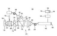
- FIGS. 1-3depict an exemplary apparatus in accordance with embodiments of the invention.
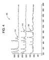
- FIG. 4depicts an illustration of exemplary Raman spectra using the apparatus of FIGS. 1-3 .
- An embodiment of the inventionprovides an apparatus for generating a Raman spectrum of a test sample, and more specifically for generating a calibrated Raman spectrum of the test sample.
- a test standard internal to the apparatusalternatively referred to as an internal standard (IS)
- ISinternal standard
- SUTsample under test
- a combination Raman spectrummay be generated using a radiation beam having a single beam path directed toward the IS and SUT.
- the combination Raman spectrummay then be analyzed and adjusted to produce a standard Raman spectrum of the SUT with system variation removed.
- system variationrefers to variations within the test apparatus, the test environment and the test sample.
- FIG. 1is an exemplary embodiment of an apparatus 100 for generating a Raman spectrum of a test sample.
- apparatus 100includes a radiation source 105 , such as a substantially monochromatic laser, for producing a test beam 110 ; a first station 115 adapted to house a test standard 120 , a second station 125 adapted to house a test sample 130 , and a spectrometer 140 containing a detector 135 .
- the term spectrometeris intended to be generally descriptive of a means to separate polychromatic light into its monochromatic components defined by a resolution or bandpass.
- Methods for separating the lightmay be based on filters, tunable filters, dispersion, separation, interferometry, or any other means suitable for obtaining monochromatic information.
- Light entering spectrometer 140is separated, thereby illuminating detector 135 to produce a spectrum of the Raman radiation from test standard 120 and/or test sample 130 .
- First and second stations 115 , 125are disposed such that each are responsive to the same test beam 110 .
- the combined Raman radiationgenerated by irradiating both test standard 120 and test sample 130 by the same test beam 110 , is used to generate a calibrated Raman spectrum of test sample 130 , which will be discussed in more detail later.
- While embodiments disclosed hereinmay refer to a spectrometer that spatially separates the Raman signal, it will be appreciated that the Raman signal may also be non-spatially separated by other techniques, such as by an interferometer, a tunable filter, or a Fourier Transform spectrometer, for example, and that the scope of the invention is not limited to only spectrometers that spatially separate the Raman signal.
- Apparatus 100may optionally include a device 155 for shuttering or switching, either mechanically or optically, the test beam 110 such that test beam 110 may or may not reach test sample 130 .
- device 155is a mechanical shutter movably disposed between a first position, depicted in solid line, and a second position, depicted in dashed line, wherein the first position allows test beam 110 to reach test sample 130 , and the second position prevents test beam 110 from reaching test sample 130 .
- device 155may be an optical shutter or an optical switch for causing the same result.
- a laser beam 160is directed through a waveguide 165 to lens 170 , laser transmission filter 175 , and laser rejection filter 180 , resulting in test beam 110 being directed toward first 115 and second 125 stations via a single beam path 195 .
- the term waveguiderefers to a means for guiding a light wave, and not necessarily to a specific structure of a specific waveguide, such as a fiber optic for example. While embodiments of the invention may employ fiber optics for waveguide 165 , other embodiments may employ a laser 105 that is an integral part of the excitation/collection optical assembly (probe) 212 , thereby eliminating the waveguide interface between the laser 105 and probe 212 .
- probe 212is depicted generally as the excitation/collection optical assembly having lenses 170 , 200 , 205 , 210 , 225 , and filters 175 , 180 , 220 , however, embodiments of the invention are not so limited and may include fewer or additional optical elements, such as the absence of laser rejection filter 180 for example.
- test beam 110In response to shutter 155 being in the first position (open), test beam 110 passes through lens 200 to first station 115 where it irradiates test standard 120 , then through lens 205 and lens 210 to second station 125 where it irradiates test sample 130 .
- test standard 120is optically transparent to test beam 110 , thereby permitting test beam 110 to pass through first station 115 and test standard 120 on its path toward second station 125 and test sample 130 .
- optically transparent test standardrefers to a test standard that will permit at least a portion of the test beam to pass through the test standard, while another portion of the same test beam may be diffused by interaction with the test standard, thereby enabling both the test standard and the test sample to be exposed to the same instance of the test beam.
- the test standardmay be fully or partially transparent or translucent, as long as a portion of the incident light is allowed to fall on the test sample. Accordingly, the invention disclosed herein is not limited to only a test standard capable of 100% transmittance.
- transparentis intended to mean having the property of transmitting rays of light such that an object may be distinctly seen through the transparent article.
- translucentis intended to mean having the property of transmitting rays of light such that an object may not be clearly seen through the translucent article.
- test beam 110passes through lens 200 to first station 115 where it irradiates test standard 120 , then only through lens 205 where it is radiated back by shutter 155 .
- shutter 155may be disposed between first station 115 and lens 205 , so that the light is blocked before reaching lens 205 .
- shutter 155is replaced by a fiber optic switch, as discussed previously.
- Raman radiationresults therefrom. Whether shutter 155 is open or closed, the resulting Raman radiation beam 215 is directed through laser rejection filter 180 , longpass filter 220 , lens 225 , and waveguide 230 , where it is received at spectrometer 140 and detector 135 .
- detector 135is a two-dimensional charge-coupled-device (CCD) that converts the separated Raman radiation to produce a spectrum.
- the two-dimensional CCD detector 135may be used in combination with a binning algorithm executed by a processing circuit, discussed later, for combining the charge from adjacent pixels in the two-dimensional CCD to produce an accumulated charge having an improved signal-to-noise ratio (SNR).
- SNRsignal-to-noise ratio
- detector 135may be a one-dimensional CCD detector.
- apparatus 100may have shuttering device 155 disposed to block light between first station 115 and lens 205 , as discussed previously, and may position a laser 105 to direct a light beam toward a mirror 235 rather than toward the laser rejection filter 180 of FIG. 1 .
- a beam splitter 240may be employed.
- Raman radiation beams from test standard 120 at first station 115 , and from test sample 130 at second station 125are combined into a single beam path 215 directed toward spectrometer 140 and detector 135 , which is similar to the single beam path 215 depicted in FIG. 1 .
- beam splitter 240may be used in combination with a change in the placement of first station 115 and test standard 120 .
- beam splitter 240directs a first beam 250 from laser 105 toward first station 115 , and a second beam 255 from laser 105 toward second station 125 .
- Raman radiation beams from test standard 120 and test sample 130are combined into a single beam path 215 , via beam splitter 240 , and directed toward spectrometer 140 and detector 135 .
- Single beam path 215 of FIG. 3is similar to the single beam paths 215 of FIGS. 1 and 2 .
- test standard 120may be opaque rather than transparent. As used herein, the term opaque is intended to mean impervious to rays of light, not transparent.
- probe 212may have a first optical path 260 adapted for coupling, via lens 170 , with radiation source 105 that produces test beam 110 , and a second optical path 265 adapted for coupling, via lens 225 , with spectrometer 140 and detector 135 .
- the Raman radiation from the test standard 120 and the test sample 130are combined at the second optical path 265 .
- the probe 212 of FIG. 2has a test beam 110 that is directed to first station 115 and second station 125 via a single beam path, such that the first and second stations are responsive to the same test beam, the probe 212 of FIG.
- either probe 212 of FIGS. 2 and 3may include a means, such as a shutter 155 for example, for preventing the test beam 110 or the second beam 255 from reaching the test sample 130 .
- the Raman radiation from test standard 120 and test sample 130may be received at spectrometer 140 and detector 135 via a single beam path 215 , thereby enabling the generation of a combined Raman spectrum by illumination of detector 135 from a single Raman beam.
- apparatus 100may also include a processing circuit 145 adapted, that is, having electronic circuitry configured and capable of executing instructions, to subtract the Raman spectrum 305 of test standard 120 , such as toluene (T) for example, from the combined Raman spectrum 310 of test standard 120 and test sample 130 , to generate a Raman spectrum 315 of test sample 130 , such as chloroform (C) for example, best seen by now referring to FIG. 4 . While only toluene and chloroform are disclosed as a test standard and test sample, respectively, it will be appreciated that any material capable of producing Raman radiation upon exposure to test beam 110 may be used in place thereof.
- a processing circuit 145adapted, that is, having electronic circuitry configured and capable of executing instructions, to subtract the Raman spectrum 305 of test standard 120 , such as toluene (T) for example, from the combined Raman spectrum 310 of test standard 120 and test sample 130 , to generate a Raman spectrum 315 of test sample 130 , such as chloroform (
- processing circuit 145is further adapted to compare the peaks of combined Raman spectrum 310 to the peaks of test standard Raman spectrum 305 , analyze the frequency difference between associated peaks, apply a frequency shift correction to combined Raman spectrum 310 thereby aligning the associated peaks, and then subtract test standard Raman spectrum 305 from combined Raman spectrum 310 , thereby producing a calibrated test sample Raman spectrum 315 .
- the aforementioned frequency shift correctionmay also, or alternatively, be applied to the spectral data collected at spectrometer 140 prior to the subtraction routine, or to test sample Raman spectrum 315 subsequent to the subtraction routine.
- Apparatus 100may further include a storage medium 150 , readable by processing circuit 145 , storing instructions for execution by processing circuit 145 , for performing the data processing disclosed herein.
- Storage medium 150may also be used for storing a library 152 of known Raman spectra.
- processing circuit 145may also be adapted to compare the Raman spectral peaks of the resulting test sample Raman spectrum 315 against the stored library of known Raman spectra, apply a best fit algorithm to match up the test sample Raman spectrum 315 with a suitable, if any, match in the library 152 , and display the resulting match information, such as the compound name or letter designation, on user display 300 .
- test sample Raman spectrum 315is chloroform having letter designation (C), but may be any number of compounds having an associated Raman spectrum stored in library 152 .
- apparatus 100may generate a calibrated Raman spectrum 315 of test sample 130 in accordance with the following exemplary method.
- an exemplary apparatus 100is selected for its ability to irradiate test standard 120 and test sample 130 using the same radiation test beam 110 , where test standard 120 and test sample 130 are arranged optically in series with each other.
- test standard 120 and/or test sample 130are irradiated.
- a beam splitter 240may be used where the resulting separate Raman beams are subsequently combined into a single Raman beam 215 .
- single test beam 110is used to irradiate test standard 120 , or test standard 120 in combination with test sample 130 .
- spectral datais collected and Raman spectrum generated therefrom, which may be a combined Raman spectrum 310 of test standard 120 and test sample 130 , or a test standard Raman spectrum 305 .
- Raman spectrum 305may be generated by operating apparatus 100 with shutter 155 closed.
- the combined Raman spectrum 310may be compared with the test standard Raman spectrum 305 , and the combined Raman spectrum 310 frequency shifted by an amount that would align the associated peaks of combined Raman spectrum 310 with those peaks of known test standard Raman spectrum 305 , thereby rendering a calibrated test sample Raman spectrum 315 .
- test standard Raman spectrum 305may be subtracted from combined Raman spectrum 310 , and then the resulting test sample Raman spectrum 315 may be frequency shifted to produce a calibrated test sample Raman spectrum 315 .
- test standard 120 and test sample 130are irradiated using a single radiation test beam 110 to generate Raman radiation, with the resulting spectral data from spectrometer 140 and detector 135 producing a combined Raman spectrum 310 .
- a test standard Raman spectrum 305may be obtained by operating apparatus 100 to irradiate only test standard 120 , which may be accomplished by closing device 155 and preventing the single radiation beam from irradiating test sample 130 .
- the test standard Raman spectrum 305is then used to render a calibrated Raman spectrum 315 of test sample 130 as discussed previously. In this manner, the calibrated Raman spectrum 315 of test sample 130 may be calibrated in real time, thereby removing real time variabilities in apparatus 100 .
- apparatus 100is used to irradiate only test standard 120 both before and after irradiating the combination of test standard 120 and test sample 130 , thereby providing both a before and after test standard Raman spectrum 305 to further show that apparatus 100 is capable of providing a properly calibrated Raman spectrum of test sample 130 .
- apparatus 100is used to split the laser beam 160 to irradiate test standard 120 and test sample 130 by separate irradiating beams, and then to combine the two resulting Raman radiation beams into a single Raman beam directed towards the spectrometer 140 and detector 135 for subsequent analysis.
- apparatus 100may be operated sequentially, first to obtain a Raman spectrum of test standard 120 (IS), and then to obtain a Raman spectrum of test sample 130 (SUT), with the resulting spectra being stored in memory 153 of storage medium 150 for subsequent data processing by processing circuit 145 .
- IStest standard 120
- SUTRaman spectrum of test sample 130
- some embodiments of the inventionmay include some of the following advantages: use of an internal test standard to ensure proper calibration; the ability to use any number of different compounds as an internal test standard; the ability to correct for calibration drift on every scan of a test sample; the use of single beam irradiation for irradiating a plurality of objects with the same energy beam (that is, no beam splitter); the use of a single Raman beam for illuminating the detector (using a beam splitter); the use of single beam irradiation of the test standard in combination with the test sample for real time simultaneous spectral data collection of the combination; the ability to compare the Raman spectrum peaks of the test standard in the actual scan of the test sample to those both before and after to confirm proper and maintained calibration; and, the ability to utilize a self-calibration Raman probe for any kind of Raman spectroscopy including surface enhanced Raman spectroscopy (SERS).
- SERSsurface enhanced Raman spectroscopy
- Embodiments of the inventionmay also be embodied in the form of computer-implemented processes and apparatuses for practicing those processes.
- the present inventionmay also be embodied in the form of computer program code containing instructions embodied in tangible media, such as floppy diskettes, CD-ROMs, hard drives, USB (universal serial bus) drives, or any other computer readable storage medium, wherein, when the computer program code is loaded into and executed by a computer, the computer becomes an apparatus for practicing the invention.
- the present inventionmay also be embodied in the form of computer program code, for example, whether stored in a storage medium, loaded into and/or executed by a computer, or transmitted over some transmission medium, such as over electrical wiring or cabling, through fiber optics, or via electromagnetic radiation, wherein when the computer program code is loaded into and executed by a computer, the computer becomes an apparatus for practicing the invention.
- the computer program code segmentsconfigure the microprocessor to create specific logic circuits.
- the technical effect of the executable instructionsis to produce a calibrated Raman spectrum of a test sample from a combined Raman spectrum and a test standard Raman spectrum.
Landscapes
- Physics & Mathematics (AREA)
- Spectroscopy & Molecular Physics (AREA)
- General Physics & Mathematics (AREA)
- Health & Medical Sciences (AREA)
- Analytical Chemistry (AREA)
- Life Sciences & Earth Sciences (AREA)
- Chemical & Material Sciences (AREA)
- Biochemistry (AREA)
- General Health & Medical Sciences (AREA)
- Immunology (AREA)
- Pathology (AREA)
- Theoretical Computer Science (AREA)
- Mathematical Physics (AREA)
- Engineering & Computer Science (AREA)
- Nuclear Medicine, Radiotherapy & Molecular Imaging (AREA)
- Investigating, Analyzing Materials By Fluorescence Or Luminescence (AREA)
Abstract
Description
Claims (31)
Priority Applications (4)
| Application Number | Priority Date | Filing Date | Title |
|---|---|---|---|
| US10/941,565US7502105B2 (en) | 2004-09-15 | 2004-09-15 | Apparatus and method for producing a calibrated Raman spectrum |
| CA002579958ACA2579958A1 (en) | 2004-09-15 | 2005-08-09 | Apparatus and method for producing a calibrated raman spectrum |
| PCT/US2005/028241WO2006036313A1 (en) | 2004-09-15 | 2005-08-09 | Apparatus and method for producing a calibrated raman spectrum |
| EP05784455AEP1792166A1 (en) | 2004-09-15 | 2005-08-09 | Apparatus and method for producing a calibrated raman spectrum |
Applications Claiming Priority (1)
| Application Number | Priority Date | Filing Date | Title |
|---|---|---|---|
| US10/941,565US7502105B2 (en) | 2004-09-15 | 2004-09-15 | Apparatus and method for producing a calibrated Raman spectrum |
Publications (2)
| Publication Number | Publication Date |
|---|---|
| US20060055919A1 US20060055919A1 (en) | 2006-03-16 |
| US7502105B2true US7502105B2 (en) | 2009-03-10 |
Family
ID=35429414
Family Applications (1)
| Application Number | Title | Priority Date | Filing Date |
|---|---|---|---|
| US10/941,565Expired - LifetimeUS7502105B2 (en) | 2004-09-15 | 2004-09-15 | Apparatus and method for producing a calibrated Raman spectrum |
Country Status (4)
| Country | Link |
|---|---|
| US (1) | US7502105B2 (en) |
| EP (1) | EP1792166A1 (en) |
| CA (1) | CA2579958A1 (en) |
| WO (1) | WO2006036313A1 (en) |
Cited By (6)
| Publication number | Priority date | Publication date | Assignee | Title |
|---|---|---|---|---|
| US20100291599A1 (en)* | 2009-05-18 | 2010-11-18 | Bruker Optics, Inc. | Large area scanning apparatus for analyte quantification by surface enhanced raman spectroscopy and method of use |
| US20170131145A1 (en)* | 2011-02-10 | 2017-05-11 | Diramed, Llc | Shutter Assembly For Calibration |
| US20190128733A1 (en)* | 2017-11-01 | 2019-05-02 | Electronics And Telecommunications Research Institute | Spectroscopic device |
| US11441950B2 (en) | 2019-12-31 | 2022-09-13 | Tornado Spectral Systems Inc. | Apparatus and method for reducing interference in an optical spectroscopy probe having a collimated sample beam |
| US20230288340A1 (en)* | 2020-07-30 | 2023-09-14 | Harry Owen | Real-time raman calibration |
| US20240102933A1 (en)* | 2018-10-16 | 2024-03-28 | Polyvalor, Limited Partnership | Methods for Performing a Raman Spectroscopy Measurement on a Sample and Raman Spectroscopy Systems |
Families Citing this family (18)
| Publication number | Priority date | Publication date | Assignee | Title |
|---|---|---|---|---|
| WO2007061436A1 (en)* | 2005-11-28 | 2007-05-31 | University Of South Carolina | Self calibration methods for optical analysis system |
| US20100265499A1 (en)* | 2006-08-07 | 2010-10-21 | Keith Carron | Programmable raman transducer |
| US7847932B2 (en)* | 2007-12-28 | 2010-12-07 | Morpho Detection, Inc. | System and method for improved biodetection |
| US20090168592A1 (en)* | 2007-12-28 | 2009-07-02 | Michael Craig Burrell | Agitator for portable substance identification system and method |
| US7852470B2 (en)* | 2007-12-28 | 2010-12-14 | Morpho Detection, Inc. | System and method for improved biodetection |
| US20090169433A1 (en)* | 2007-12-28 | 2009-07-02 | Sankaran Kumar | System for improved biodetection |
| US20100077843A1 (en)* | 2008-03-31 | 2010-04-01 | Doraisamy Loganathan | Substance identification apparatus and methods of using |
| WO2010034017A2 (en)* | 2008-09-22 | 2010-03-25 | Life Technologies Corporation | Systems and methods for signal normalization using raman scattering |
| CN102608095A (en)* | 2010-06-25 | 2012-07-25 | 清华大学 | Method for automatically calibrating Raman spectrum detection system by utilizing standard sample |
| JP5092104B2 (en)* | 2010-08-30 | 2012-12-05 | ナノフォトン株式会社 | Spectrometer and spectroscopic method |
| CN103518121A (en)* | 2011-01-26 | 2014-01-15 | 技术信息有限公司 | An emission spectrometer and method of operation |
| GB201503911D0 (en)* | 2015-03-09 | 2015-04-22 | Renishaw Plc | Transmission raman spectroscopy |
| US10088422B2 (en)* | 2015-12-28 | 2018-10-02 | Schlumberger Technology Corporation | Raman spectroscopy for determination of composition of natural gas |
| FR3065285B1 (en)* | 2017-04-14 | 2019-07-05 | Commissariat A L'energie Atomique Et Aux Energies Alternatives | METHOD FOR ACQUIRING A SPECTRUM |
| CN108106732B (en)* | 2017-12-01 | 2020-06-09 | 中国计量科学研究院 | Method and device for calibrating wave number resolution of Raman spectrometer |
| EP3734243A1 (en)* | 2019-05-01 | 2020-11-04 | Kaiser Optical Systems Inc. | Standard reference material interface for raman probe |
| CN114441505B (en)* | 2022-03-17 | 2023-08-18 | 中国工程物理研究院机械制造工艺研究所 | Water vapor in-situ calibration device for Raman probe, calibration method and application |
| FR3158793A1 (en)* | 2024-01-26 | 2025-08-01 | Horiba France Sas | System and method for measuring an effective concentration of at least one chemical component of a flowing fluid |
Citations (10)
| Publication number | Priority date | Publication date | Assignee | Title |
|---|---|---|---|---|
| US5020909A (en)* | 1990-03-02 | 1991-06-04 | Landa Issac J | "In-line" spectral reference method for spectrometers |
| US5404218A (en)* | 1993-11-18 | 1995-04-04 | The United States Of America As Represented By The United States Department Of Energy | Fiber optic probe for light scattering measurements |
| US5455673A (en) | 1994-05-27 | 1995-10-03 | Eastman Chemical Company | Apparatus and method for measuring and applying a convolution function to produce a standard Raman spectrum |
| US5526121A (en)* | 1990-10-01 | 1996-06-11 | Eastman Kodak Company | Variable filter spectrophotometers |
| US5850623A (en)* | 1997-03-14 | 1998-12-15 | Eastman Chemical Company | Method for standardizing raman spectrometers to obtain stable and transferable calibrations |
| US6067156A (en)* | 1997-05-16 | 2000-05-23 | Kaiser Optical Systems | Wavelength calibration and tracking methods and apparatus |
| US6141095A (en) | 1998-06-10 | 2000-10-31 | New Chromex, Inc. | Apparatus for measuring and applying instrumentation correction to produce a standard Raman spectrum |
| US6281971B1 (en) | 1999-05-18 | 2001-08-28 | New Chromex, Inc. | Method for adjusting spectral measurements to produce a standard Raman spectrum |
| US6621574B1 (en)* | 2000-05-25 | 2003-09-16 | Inphotonics, Inc. | Dual function safety and calibration accessory for raman and other spectroscopic sampling |
| US6897951B2 (en) | 2003-02-14 | 2005-05-24 | Raman Systems, Inc. | Probe assemblies for Raman spectroscopy |
Family Cites Families (4)
| Publication number | Priority date | Publication date | Assignee | Title |
|---|---|---|---|---|
| US5510894A (en)* | 1988-12-22 | 1996-04-23 | Renishaw Plc | Spectroscopic apparatus and methods |
| US5638172A (en)* | 1994-05-27 | 1997-06-10 | Eastman Chemical Company | On-line quantitative analysis of chemical compositions by raman spectrometry |
| JPH0915156A (en)* | 1995-06-28 | 1997-01-17 | Kdk Corp | Spectroscopic measuring method and measuring device |
| FR2841984B1 (en)* | 2002-07-03 | 2004-11-12 | Jobin Yvon Sa | DIFFERENTIAL ANALYSIS SYSTEM FOR ANALYTICAL AND INDUSTRIAL RAMAN SPECTROMETRY |
- 2004
- 2004-09-15USUS10/941,565patent/US7502105B2/ennot_activeExpired - Lifetime
- 2005
- 2005-08-09CACA002579958Apatent/CA2579958A1/ennot_activeAbandoned
- 2005-08-09WOPCT/US2005/028241patent/WO2006036313A1/enactiveApplication Filing
- 2005-08-09EPEP05784455Apatent/EP1792166A1/ennot_activeWithdrawn
Patent Citations (10)
| Publication number | Priority date | Publication date | Assignee | Title |
|---|---|---|---|---|
| US5020909A (en)* | 1990-03-02 | 1991-06-04 | Landa Issac J | "In-line" spectral reference method for spectrometers |
| US5526121A (en)* | 1990-10-01 | 1996-06-11 | Eastman Kodak Company | Variable filter spectrophotometers |
| US5404218A (en)* | 1993-11-18 | 1995-04-04 | The United States Of America As Represented By The United States Department Of Energy | Fiber optic probe for light scattering measurements |
| US5455673A (en) | 1994-05-27 | 1995-10-03 | Eastman Chemical Company | Apparatus and method for measuring and applying a convolution function to produce a standard Raman spectrum |
| US5850623A (en)* | 1997-03-14 | 1998-12-15 | Eastman Chemical Company | Method for standardizing raman spectrometers to obtain stable and transferable calibrations |
| US6067156A (en)* | 1997-05-16 | 2000-05-23 | Kaiser Optical Systems | Wavelength calibration and tracking methods and apparatus |
| US6141095A (en) | 1998-06-10 | 2000-10-31 | New Chromex, Inc. | Apparatus for measuring and applying instrumentation correction to produce a standard Raman spectrum |
| US6281971B1 (en) | 1999-05-18 | 2001-08-28 | New Chromex, Inc. | Method for adjusting spectral measurements to produce a standard Raman spectrum |
| US6621574B1 (en)* | 2000-05-25 | 2003-09-16 | Inphotonics, Inc. | Dual function safety and calibration accessory for raman and other spectroscopic sampling |
| US6897951B2 (en) | 2003-02-14 | 2005-05-24 | Raman Systems, Inc. | Probe assemblies for Raman spectroscopy |
Non-Patent Citations (1)
| Title |
|---|
| Favors, Ryan, New Raman External Standard for Absolute Intensity and Concentration Measurements, Chemistry Department, Purdue University West Lafayette, IN, United States, presented at Federation of Analytical Chemistry and Spectroscopy Societies (Oct. 2002). |
Cited By (8)
| Publication number | Priority date | Publication date | Assignee | Title |
|---|---|---|---|---|
| US20100291599A1 (en)* | 2009-05-18 | 2010-11-18 | Bruker Optics, Inc. | Large area scanning apparatus for analyte quantification by surface enhanced raman spectroscopy and method of use |
| US20170131145A1 (en)* | 2011-02-10 | 2017-05-11 | Diramed, Llc | Shutter Assembly For Calibration |
| US10436641B2 (en)* | 2011-02-10 | 2019-10-08 | Diramed, Llc | Shutter assembly for calibration |
| US20190128733A1 (en)* | 2017-11-01 | 2019-05-02 | Electronics And Telecommunications Research Institute | Spectroscopic device |
| US10648860B2 (en)* | 2017-11-01 | 2020-05-12 | Electronics And Telecommunications Research Institute | Spectroscopic device |
| US20240102933A1 (en)* | 2018-10-16 | 2024-03-28 | Polyvalor, Limited Partnership | Methods for Performing a Raman Spectroscopy Measurement on a Sample and Raman Spectroscopy Systems |
| US11441950B2 (en) | 2019-12-31 | 2022-09-13 | Tornado Spectral Systems Inc. | Apparatus and method for reducing interference in an optical spectroscopy probe having a collimated sample beam |
| US20230288340A1 (en)* | 2020-07-30 | 2023-09-14 | Harry Owen | Real-time raman calibration |
Also Published As
| Publication number | Publication date |
|---|---|
| US20060055919A1 (en) | 2006-03-16 |
| WO2006036313A1 (en) | 2006-04-06 |
| EP1792166A1 (en) | 2007-06-06 |
| CA2579958A1 (en) | 2006-04-06 |
Similar Documents
| Publication | Publication Date | Title |
|---|---|---|
| US7502105B2 (en) | Apparatus and method for producing a calibrated Raman spectrum | |
| US7745789B2 (en) | Measuring technique | |
| US8873041B1 (en) | Raman spectroscopy using multiple excitation wavelengths | |
| US8693004B2 (en) | Dual-etalon cavity ring-down frequency-comb spectroscopy with broad band light source | |
| US6794670B1 (en) | Method and apparatus for spectrometric analysis of turbid, pharmaceutical samples | |
| KR20120012391A (en) | Sample Inspection Device and Sample Inspection Method | |
| JP2004509324A (en) | How to adjust the spectroscopic data of a sample and generate a standard Raman spectrum | |
| JPH0915156A (en) | Spectroscopic measuring method and measuring device | |
| JP2022502660A (en) | Raman spectrometer | |
| WO2005074525A2 (en) | Entangled-photon fourier transform spectroscopy | |
| US20100014076A1 (en) | Spectrometric apparatus for measuring shifted spectral distributions | |
| US12392733B2 (en) | Combined ocd and photoreflectance method and system | |
| JP2000055809A (en) | Micro-Raman spectrometer and micro-Raman spectroscopic measurement method | |
| JP2000314703A (en) | Search for active compound and equipment used therefor | |
| US20250093269A1 (en) | Method for enhancing a raman contribution in a spectrum, spectroscopy system, computer program and non-transitory computer-readable storage medium | |
| RU2567119C1 (en) | Method for remote wireless detection and identification of chemical substances and organic objects and device therefor | |
| JP2002055052A (en) | Laser Raman spectrometer and laser Raman spectrometer | |
| WO2021189129A1 (en) | A system and method for detecting single elemental emission lines in a glow discharge | |
| Lisitsyn et al. | Time-resolved multispectral luminescence method for analysis of minerals |
Legal Events
| Date | Code | Title | Description |
|---|---|---|---|
| AS | Assignment | Owner name:GENERAL ELECTRIC COMPANY, NEW YORK Free format text:ASSIGNMENT OF ASSIGNORS INTEREST;ASSIGNORS:LEE, YUAN-HSIANG;SUTHERLAND, WILLIAM SCOTT;REEL/FRAME:015802/0913 Effective date:20040909 | |
| AS | Assignment | Owner name:GE HOMELAND PROTECTION, INC.,CALIFORNIA Free format text:ASSIGNMENT OF ASSIGNORS INTEREST;ASSIGNOR:GENERAL ELECTRIC COMPANY;REEL/FRAME:019304/0798 Effective date:20070518 Owner name:GE HOMELAND PROTECTION, INC., CALIFORNIA Free format text:ASSIGNMENT OF ASSIGNORS INTEREST;ASSIGNOR:GENERAL ELECTRIC COMPANY;REEL/FRAME:019304/0798 Effective date:20070518 | |
| FEPP | Fee payment procedure | Free format text:PAYOR NUMBER ASSIGNED (ORIGINAL EVENT CODE: ASPN); ENTITY STATUS OF PATENT OWNER: LARGE ENTITY | |
| STCF | Information on status: patent grant | Free format text:PATENTED CASE | |
| AS | Assignment | Owner name:MORPHO DETECTION, INC., CALIFORNIA Free format text:CHANGE OF NAME;ASSIGNOR:GE HOMELAND PROTECTION, INC.;REEL/FRAME:024879/0227 Effective date:20091001 | |
| FEPP | Fee payment procedure | Free format text:PAYER NUMBER DE-ASSIGNED (ORIGINAL EVENT CODE: RMPN); ENTITY STATUS OF PATENT OWNER: LARGE ENTITY Free format text:PAYOR NUMBER ASSIGNED (ORIGINAL EVENT CODE: ASPN); ENTITY STATUS OF PATENT OWNER: LARGE ENTITY | |
| FPAY | Fee payment | Year of fee payment:4 | |
| AS | Assignment | Owner name:MORPHO DETECTION, LLC, CALIFORNIA Free format text:CHANGE OF NAME;ASSIGNOR:MORPHO DETECTION, INC.;REEL/FRAME:032122/0067 Effective date:20131230 | |
| AS | Assignment | Owner name:MORPHO DETECTION, LLC, CALIFORNIA Free format text:CORRECTIVE ASSIGNMENT TO CORRECT THE THE PURPOSE OF THE CORRECTION IS TO ADD THE CERTIFICATE OF CONVERSION PAGE TO THE ORIGINALLY FILED CHANGE OF NAME DOCUMENT PREVIOUSLY RECORDED ON REEL 032122 FRAME 67. ASSIGNOR(S) HEREBY CONFIRMS THE THE CHANGE OF NAME;ASSIGNOR:MORPHO DETECTION, INC.;REEL/FRAME:032470/0682 Effective date:20131230 | |
| FPAY | Fee payment | Year of fee payment:8 | |
| MAFP | Maintenance fee payment | Free format text:PAYMENT OF MAINTENANCE FEE, 12TH YEAR, LARGE ENTITY (ORIGINAL EVENT CODE: M1553); ENTITY STATUS OF PATENT OWNER: LARGE ENTITY Year of fee payment:12 |