US7500977B2 - Method and apparatus for manipulating material in the spine - Google Patents
Method and apparatus for manipulating material in the spineDownload PDFInfo
- Publication number
- US7500977B2 US7500977B2US10/972,077US97207704AUS7500977B2US 7500977 B2US7500977 B2US 7500977B2US 97207704 AUS97207704 AUS 97207704AUS 7500977 B2US7500977 B2US 7500977B2
- Authority
- US
- United States
- Prior art keywords
- cutter
- shaft
- sheath
- blade
- guide pin
- Prior art date
- Legal status (The legal status is an assumption and is not a legal conclusion. Google has not performed a legal analysis and makes no representation as to the accuracy of the status listed.)
- Expired - Fee Related, expires
Links
Images


Classifications
- A—HUMAN NECESSITIES
- A61—MEDICAL OR VETERINARY SCIENCE; HYGIENE
- A61B—DIAGNOSIS; SURGERY; IDENTIFICATION
- A61B17/00—Surgical instruments, devices or methods
- A61B17/02—Surgical instruments, devices or methods for holding wounds open, e.g. retractors; Tractors
- A61B17/025—Joint distractors
- A—HUMAN NECESSITIES
- A61—MEDICAL OR VETERINARY SCIENCE; HYGIENE
- A61B—DIAGNOSIS; SURGERY; IDENTIFICATION
- A61B17/00—Surgical instruments, devices or methods
- A61B17/56—Surgical instruments or methods for treatment of bones or joints; Devices specially adapted therefor
- A61B17/58—Surgical instruments or methods for treatment of bones or joints; Devices specially adapted therefor for osteosynthesis, e.g. bone plates, screws or setting implements
- A61B17/88—Osteosynthesis instruments; Methods or means for implanting or extracting internal or external fixation devices
- A—HUMAN NECESSITIES
- A61—MEDICAL OR VETERINARY SCIENCE; HYGIENE
- A61B—DIAGNOSIS; SURGERY; IDENTIFICATION
- A61B17/00—Surgical instruments, devices or methods
- A61B17/56—Surgical instruments or methods for treatment of bones or joints; Devices specially adapted therefor
- A61B17/58—Surgical instruments or methods for treatment of bones or joints; Devices specially adapted therefor for osteosynthesis, e.g. bone plates, screws or setting implements
- A61B17/68—Internal fixation devices, including fasteners and spinal fixators, even if a part thereof projects from the skin
- A61B17/70—Spinal positioners or stabilisers, e.g. stabilisers comprising fluid filler in an implant
- A61B17/7074—Tools specially adapted for spinal fixation operations other than for bone removal or filler handling
- A—HUMAN NECESSITIES
- A61—MEDICAL OR VETERINARY SCIENCE; HYGIENE
- A61B—DIAGNOSIS; SURGERY; IDENTIFICATION
- A61B17/00—Surgical instruments, devices or methods
- A61B17/16—Instruments for performing osteoclasis; Drills or chisels for bones; Trepans
- A61B17/1604—Chisels; Rongeurs; Punches; Stamps
- A—HUMAN NECESSITIES
- A61—MEDICAL OR VETERINARY SCIENCE; HYGIENE
- A61B—DIAGNOSIS; SURGERY; IDENTIFICATION
- A61B17/00—Surgical instruments, devices or methods
- A61B17/16—Instruments for performing osteoclasis; Drills or chisels for bones; Trepans
- A61B17/1662—Instruments for performing osteoclasis; Drills or chisels for bones; Trepans for particular parts of the body
- A61B17/1671—Instruments for performing osteoclasis; Drills or chisels for bones; Trepans for particular parts of the body for the spine
- A—HUMAN NECESSITIES
- A61—MEDICAL OR VETERINARY SCIENCE; HYGIENE
- A61B—DIAGNOSIS; SURGERY; IDENTIFICATION
- A61B17/00—Surgical instruments, devices or methods
- A61B17/16—Instruments for performing osteoclasis; Drills or chisels for bones; Trepans
- A61B17/1697—Instruments for performing osteoclasis; Drills or chisels for bones; Trepans specially adapted for wire insertion
- A—HUMAN NECESSITIES
- A61—MEDICAL OR VETERINARY SCIENCE; HYGIENE
- A61B—DIAGNOSIS; SURGERY; IDENTIFICATION
- A61B17/00—Surgical instruments, devices or methods
- A61B17/16—Instruments for performing osteoclasis; Drills or chisels for bones; Trepans
- A61B17/17—Guides or aligning means for drills, mills, pins or wires
- A61B17/1739—Guides or aligning means for drills, mills, pins or wires specially adapted for particular parts of the body
- A61B17/1757—Guides or aligning means for drills, mills, pins or wires specially adapted for particular parts of the body for the spine
- A—HUMAN NECESSITIES
- A61—MEDICAL OR VETERINARY SCIENCE; HYGIENE
- A61B—DIAGNOSIS; SURGERY; IDENTIFICATION
- A61B17/00—Surgical instruments, devices or methods
- A61B17/22—Implements for squeezing-off ulcers or the like on inner organs of the body; Implements for scraping-out cavities of body organs, e.g. bones; for invasive removal or destruction of calculus using mechanical vibrations; for removing obstructions in blood vessels, not otherwise provided for
- A—HUMAN NECESSITIES
- A61—MEDICAL OR VETERINARY SCIENCE; HYGIENE
- A61B—DIAGNOSIS; SURGERY; IDENTIFICATION
- A61B17/00—Surgical instruments, devices or methods
- A61B17/56—Surgical instruments or methods for treatment of bones or joints; Devices specially adapted therefor
- A61B17/58—Surgical instruments or methods for treatment of bones or joints; Devices specially adapted therefor for osteosynthesis, e.g. bone plates, screws or setting implements
- A61B17/68—Internal fixation devices, including fasteners and spinal fixators, even if a part thereof projects from the skin
- A61B17/84—Fasteners therefor or fasteners being internal fixation devices
- A61B17/86—Pins or screws or threaded wires; nuts therefor
- A61B17/8605—Heads, i.e. proximal ends projecting from bone
- A61B17/861—Heads, i.e. proximal ends projecting from bone specially shaped for gripping driver
- A61B17/8615—Heads, i.e. proximal ends projecting from bone specially shaped for gripping driver at the central region of the screw head
- A—HUMAN NECESSITIES
- A61—MEDICAL OR VETERINARY SCIENCE; HYGIENE
- A61B—DIAGNOSIS; SURGERY; IDENTIFICATION
- A61B17/00—Surgical instruments, devices or methods
- A61B17/56—Surgical instruments or methods for treatment of bones or joints; Devices specially adapted therefor
- A61B17/58—Surgical instruments or methods for treatment of bones or joints; Devices specially adapted therefor for osteosynthesis, e.g. bone plates, screws or setting implements
- A61B17/88—Osteosynthesis instruments; Methods or means for implanting or extracting internal or external fixation devices
- A61B17/8875—Screwdrivers, spanners or wrenches
- A61B17/8877—Screwdrivers, spanners or wrenches characterised by the cross-section of the driver bit
- A61B17/888—Screwdrivers, spanners or wrenches characterised by the cross-section of the driver bit the driver bit acting on the central region of the screw head
- A—HUMAN NECESSITIES
- A61—MEDICAL OR VETERINARY SCIENCE; HYGIENE
- A61B—DIAGNOSIS; SURGERY; IDENTIFICATION
- A61B17/00—Surgical instruments, devices or methods
- A61B17/56—Surgical instruments or methods for treatment of bones or joints; Devices specially adapted therefor
- A61B17/58—Surgical instruments or methods for treatment of bones or joints; Devices specially adapted therefor for osteosynthesis, e.g. bone plates, screws or setting implements
- A61B17/88—Osteosynthesis instruments; Methods or means for implanting or extracting internal or external fixation devices
- A61B17/8875—Screwdrivers, spanners or wrenches
- A61B17/8886—Screwdrivers, spanners or wrenches holding the screw head
- A61B17/8888—Screwdrivers, spanners or wrenches holding the screw head at its central region
- A—HUMAN NECESSITIES
- A61—MEDICAL OR VETERINARY SCIENCE; HYGIENE
- A61B—DIAGNOSIS; SURGERY; IDENTIFICATION
- A61B17/00—Surgical instruments, devices or methods
- A61B17/56—Surgical instruments or methods for treatment of bones or joints; Devices specially adapted therefor
- A61B17/58—Surgical instruments or methods for treatment of bones or joints; Devices specially adapted therefor for osteosynthesis, e.g. bone plates, screws or setting implements
- A61B17/88—Osteosynthesis instruments; Methods or means for implanting or extracting internal or external fixation devices
- A61B17/92—Impactors or extractors, e.g. for removing intramedullary devices
- A—HUMAN NECESSITIES
- A61—MEDICAL OR VETERINARY SCIENCE; HYGIENE
- A61B—DIAGNOSIS; SURGERY; IDENTIFICATION
- A61B17/00—Surgical instruments, devices or methods
- A61B17/02—Surgical instruments, devices or methods for holding wounds open, e.g. retractors; Tractors
- A61B17/0218—Surgical instruments, devices or methods for holding wounds open, e.g. retractors; Tractors for minimally invasive surgery
- A—HUMAN NECESSITIES
- A61—MEDICAL OR VETERINARY SCIENCE; HYGIENE
- A61B—DIAGNOSIS; SURGERY; IDENTIFICATION
- A61B17/00—Surgical instruments, devices or methods
- A61B17/16—Instruments for performing osteoclasis; Drills or chisels for bones; Trepans
- A61B17/1613—Component parts
- A61B17/1615—Drill bits, i.e. rotating tools extending from a handpiece to contact the worked material
- A—HUMAN NECESSITIES
- A61—MEDICAL OR VETERINARY SCIENCE; HYGIENE
- A61B—DIAGNOSIS; SURGERY; IDENTIFICATION
- A61B17/00—Surgical instruments, devices or methods
- A61B17/56—Surgical instruments or methods for treatment of bones or joints; Devices specially adapted therefor
- A61B17/58—Surgical instruments or methods for treatment of bones or joints; Devices specially adapted therefor for osteosynthesis, e.g. bone plates, screws or setting implements
- A61B17/88—Osteosynthesis instruments; Methods or means for implanting or extracting internal or external fixation devices
- A61B17/8897—Guide wires or guide pins
- A—HUMAN NECESSITIES
- A61—MEDICAL OR VETERINARY SCIENCE; HYGIENE
- A61B—DIAGNOSIS; SURGERY; IDENTIFICATION
- A61B17/00—Surgical instruments, devices or methods
- A61B17/00234—Surgical instruments, devices or methods for minimally invasive surgery
- A61B2017/00238—Type of minimally invasive operation
- A61B2017/00261—Discectomy
- A—HUMAN NECESSITIES
- A61—MEDICAL OR VETERINARY SCIENCE; HYGIENE
- A61B—DIAGNOSIS; SURGERY; IDENTIFICATION
- A61B17/00—Surgical instruments, devices or methods
- A61B2017/0046—Surgical instruments, devices or methods with a releasable handle; with handle and operating part separable
- A—HUMAN NECESSITIES
- A61—MEDICAL OR VETERINARY SCIENCE; HYGIENE
- A61B—DIAGNOSIS; SURGERY; IDENTIFICATION
- A61B17/00—Surgical instruments, devices or methods
- A61B2017/0046—Surgical instruments, devices or methods with a releasable handle; with handle and operating part separable
- A61B2017/00469—Surgical instruments, devices or methods with a releasable handle; with handle and operating part separable for insertion of instruments, e.g. guide wire, optical fibre
- A—HUMAN NECESSITIES
- A61—MEDICAL OR VETERINARY SCIENCE; HYGIENE
- A61B—DIAGNOSIS; SURGERY; IDENTIFICATION
- A61B17/00—Surgical instruments, devices or methods
- A61B17/02—Surgical instruments, devices or methods for holding wounds open, e.g. retractors; Tractors
- A61B17/025—Joint distractors
- A61B2017/0256—Joint distractors for the spine
- A—HUMAN NECESSITIES
- A61—MEDICAL OR VETERINARY SCIENCE; HYGIENE
- A61B—DIAGNOSIS; SURGERY; IDENTIFICATION
- A61B17/00—Surgical instruments, devices or methods
- A61B17/22—Implements for squeezing-off ulcers or the like on inner organs of the body; Implements for scraping-out cavities of body organs, e.g. bones; for invasive removal or destruction of calculus using mechanical vibrations; for removing obstructions in blood vessels, not otherwise provided for
- A61B2017/22038—Implements for squeezing-off ulcers or the like on inner organs of the body; Implements for scraping-out cavities of body organs, e.g. bones; for invasive removal or destruction of calculus using mechanical vibrations; for removing obstructions in blood vessels, not otherwise provided for with a guide wire
- A61B2017/22042—Details of the tip of the guide wire
- A61B2017/22044—Details of the tip of the guide wire with a pointed tip
- A—HUMAN NECESSITIES
- A61—MEDICAL OR VETERINARY SCIENCE; HYGIENE
- A61B—DIAGNOSIS; SURGERY; IDENTIFICATION
- A61B17/00—Surgical instruments, devices or methods
- A61B17/34—Trocars; Puncturing needles
- A61B17/3417—Details of tips or shafts, e.g. grooves, expandable, bendable; Multiple coaxial sliding cannulas, e.g. for dilating
- A61B17/3421—Cannulas
- A61B2017/3445—Cannulas used as instrument channel for multiple instruments
- A—HUMAN NECESSITIES
- A61—MEDICAL OR VETERINARY SCIENCE; HYGIENE
- A61B—DIAGNOSIS; SURGERY; IDENTIFICATION
- A61B17/00—Surgical instruments, devices or methods
- A61B17/56—Surgical instruments or methods for treatment of bones or joints; Devices specially adapted therefor
- A61B17/58—Surgical instruments or methods for treatment of bones or joints; Devices specially adapted therefor for osteosynthesis, e.g. bone plates, screws or setting implements
- A61B17/88—Osteosynthesis instruments; Methods or means for implanting or extracting internal or external fixation devices
- A61B17/92—Impactors or extractors, e.g. for removing intramedullary devices
- A61B2017/922—Devices for impaction, impact element
Definitions
- the present inventionrelates generally to instrumentation systems and methods for accessing and preparing treatment sites within the spine (e.g., inter-vertebral motion segments) for subsequent therapeutic procedures, such as, for example, spinal arthroplasty, partial or total disc replacement, annulus repair, vertebroplasty, arthrodesis (fusion), or the like.
- various tools and methods of usee.g., surgical cutting devices, tissue extractors, etc.
- minimally-invasive treatment procedurese.g., low trauma disc nucleectomy via trans-sacral axial access.
- the methodscan involve, among other things, facilitating the removal of resulting tissue fragments, preparing an intervertebral disc space for subsequent deployment of spinal fusion designed to relieve lower back pain, or motion preservation devices, e.g., dynamic stabilization, devices, prosthetic nucleus devices and total disc replacements designed to relieve lower back pain and to restore physiological function of the lumbar spine, maintain and possibly improve disc health and prevent progression or transition of disease.
- motion preservation devicese.g., dynamic stabilization, devices, prosthetic nucleus devices and total disc replacements designed to relieve lower back pain and to restore physiological function of the lumbar spine, maintain and possibly improve disc health and prevent progression or transition of disease.
- Chronic lower back painis a primary cause of lost work days in the United States, and as such is a significant factor affecting both workforce productivity and health care expense.
- Therapeutic procedures for alleviating back painrange from conservative methods, e.g., with intermittent heat, rest, rehabilitative exercises, and medications to relieve pain, muscle spasm, and inflammation, to progressively more active and invasive surgical means which may be indicated if these treatments are unsuccessful, including various spinal arthroplasties, and eventually even spinal arthrodesis, i.e., surgical fusion.
- the pain generatorsare hypothesized to comprise one or more of the following: bulging of the posterior annulus or PLL with subsequent nerve impingement; tears, fissures or cracks in the outer, innervated layers of the annulus; motion induced leakage of nuclear material through the annulus and subsequent irritation of surrounding tissue in response to the foreign body reaction, or facet pain.
- bulging of the posterior annulus or PLL with subsequent nerve impingementtears, fissures or cracks in the outer, innervated layers of the annulus
- motion induced leakage of nuclear material through the annulus and subsequent irritation of surrounding tissue in response to the foreign body reaction, or facet painGenerally it is believed that 75% of cases are associated with degenerative disc disease, where the intervertebral disc of the spine suffers reduced mechanical functionality due to dehydration of the nucleus pulposus.
- the intervertebral discslocated anterior to the vertebral canal, are formed of fibrous cartilage, and comprise the posterior and anterior longitudinal ligaments and the annulus fibrosis, circumferentially enclosing a central mass, the.
- the nucleus pulposusprovides for cushioning and dampening of compressive forces to the spinal column. In a healthy adult spine, it comprises 80% water.
- Surgical proceduressuch as spinal fusion and discectomy, may alleviate pain, but do not restore normal physiological disc function.
- the vertebraeare the bony building blocks of the spine. Between each of the vertebral bodies are the spinal discs and this unit, comprising two vertebral bodies interfaced by an intermediate spinal disc, is known as a spinal motion segment.
- the spinehas seven vertebrae in the neck (cervical vertebrae), twelve vertebrae in the mid-back (thoracic vertebrae), and five vertebrae in the low back (lumbar vertebrae). All of the vertebrae and discs are held together or surrounded by means of ligaments, which are strong fibrous soft tissues that firmly attach bones to bones.
- Ligamentscontribute to the normal physiologic range of motion of the spine, and if injured, e.g., due to disc degeneration (described below) and ensuing impact on distribution of physiologic loads, they similarly may contribute to the resulting pain.
- the bony spineis designed so that vertebrae “stacked” together can provide a movable support structure while also protecting the spinal cord's nervous tissue that extends down the spinal column from the brain from injury.
- Each vertebrahas a spinous process, which is a bony prominence behind the spinal cord that shields the cord's nerve tissue.
- the vertebraealso have a strong bony “body” in front of the spinal cord to provide a platform suitable for weight-bearing.
- the spinal discsserve as “dampeners” between each vertebral body that minimize the impact of movement on the spinal column.
- Each discis comprised of the nucleus pulposus, a central, softer component, contained with in the, a surrounding outer ring.
- the spinal discs and the facet joints that stack the vertebrae, both of which are partly composed of cartilageare subject to similar degradation over time.
- the gradual deterioration of the disc between the vertebraeis known as degenerative disc disease, or spondylosis. Spondylosis is depicted on x-ray tests or MRI scanning of the spine as a narrowing of the normal “disc space” between adjacent vertebrae.
- Radiculopathyrefers to nerve irritation caused by damage to the disc between the vertebrae. This occurs because of degeneration of the annulus fibrosis of the disc, or due to traumatic injury, or both. Weakening of the annulus may lead to disc bulging and herniation, i.e., the nucleus pulposus or softer portion of the disc can rupture through the annulus and abut the spinal cord or its nerves as they exit the bony spinal column. When disc herniation occurs, the rupture of the nucleus pulposus the annulus fibrosis may irritate adjacent nervous tissue, causing local pain, or discogenic pain, in the affected area. Any level of the spine can be affected by disc degeneration.
- disc degenerationaffects the spine of the neck, it is referred to as cervical disc disease, while when the mid-back is affected, the condition is referred to as thoracic disc disease.
- Disc degeneration that affects the lumbar spinecauses pain localized to the low back and is sometimes common in older persons and known as lumbago Degenerative arthritis (osteoarthritis) of the facet joints is also a cause of localized lumbar pain that can be diagnosed via x-ray analysis.
- the pain from degenerative disc or joint disease of the spinemay be treated conservatively with intermittent heat, rest, rehabilitative exercises, and medications to relieve pain, muscle spasm, and inflammation, but if these treatments are unsuccessful, progressively more active interventions may be indicated, including spinal arthroplasty including prosthetic nucleus device implantation; annulus repair, and total disc replacement, and eventually, even spinal arthrodesis,
- spinal arthroplastyincluding prosthetic nucleus device implantation; annulus repair, and total disc replacement, and eventually, even spinal arthrodesis
- the intervention performeddepends on the overall status of the spine, and the age and health of the patient. Procedures include removal of the herniated disc with laminotomy (a small hole in the bone of the spine surrounding the spinal cord), laminectomy (removal of the bony wall), by needle technique through the skin (percutaneous discectomy), disc-dissolving procedures (chemonucleolysis), and others.
- spinal stenosisoccurs most often in the lumbar spine, i.e., the lower back, but also occurs in the cervical spine and less often in the thoracic spine. It is most often caused by degeneration of the discs between the vertebrae due to osteoarthritis. Rheumatoid arthritis usually affects people at an earlier age than osteoarthritis does and is associated with inflammation and enlargement of the soft tissues of the joints.
- Non-arthritic causes of spinal stenosisinclude tumors of the spine, trauma, Paget's disease of bone, and fluorosis.
- spinal arthroplastyencompasses options for treating disc degeneration when arthrodesis is deemed too radical an intervention based on an assessment of the patient's age, degree of disc degeneration, and prognosis.
- the preferred embodiments of the inventioninvolve surgical tools sets and methods for accessing and preparing vertebral elements, such as inter-vertebral motion segments located within a human lumbar and sacral spine, for therapeutic procedures.
- vertebral elementssuch as inter-vertebral motion segments located within a human lumbar and sacral spine, for therapeutic procedures.
- motion segmentscomprise adjacent vertebrae separated by intact or damaged spinal discs.
- instrumentation system components and their means of useindividually and in combination and over or through one another, form or enlarge a posterior or anterior percutaneous tract; access, fragment and extract tissue (e.g., nucleus pulposus); or otherwise prepare vertebral elements and inter-vertebral motion segments for fusion or dynamic stabilization via implantation of therapeutic agents and materials and spinal devices, are disclosed.
- fragment and extract tissuee.g., nucleus pulposus
- vertebral elements and inter-vertebral motion segmentsfor fusion or dynamic stabilization via implantation of therapeutic agents and materials and spinal devices.
- the tools describedcan be used for and with the introduction of any number of devices, such as, for example, fusion devices, mobility devices, etc.
- Instrumentationis introduced and aligned (e.g., via preferably fluoroscopy, endoscopy, or other radio-imaging means, used as guidance to insure that the channel is positioned mid-line or along another desired reference axis relative to the anterior/posterior and lateral sacral view) through the percutaneous pathways and according to the trans-sacral axial access methods disclosed by Cragg, in commonly assigned U.S. Pat. Nos. 6,558,386, 6,558,390, and 6,575,979, each incorporated herein in their entirely by reference.
- the present inventionprovides a series of surgical tools and devices, wherein the preferred embodiments of each are configured and constructed (e.g., cannulated; solid; blunt; beveled; angled; retractable; fixed; tilted; axially aligned; offset; extendible; exchangeable; stiff; flexible; deformable; recoverable; anchored; removable; biocompatible; able to be sterilized & machined; moldable; reusable; disposable) in accordance with optimal intended function and in deference to biomechanical and safety constraints.
- the preferred embodiments of eachare configured and constructed (e.g., cannulated; solid; blunt; beveled; angled; retractable; fixed; tilted; axially aligned; offset; extendible; exchangeable; stiff; flexible; deformable; recoverable; anchored; removable; biocompatible; able to be sterilized & machined; moldable; reusable; disposable) in accordance with optimal intended function and in deference to biomechanical and safety constraints.
- Certain of the surgical toolstake the form of elongated solid body members extending from proximal to distal ends thereof. Such solid body members may be used in combination or sequentially with elongated, cannulated body members.
- design constraintsin addition to outside diameter (O.D.) tolerances and limitations imposed by virtue of patient anatomies, such as tube wall thickness, material selection/mechanical strength, and inside diameter (I.D.) also become considerations, e.g., to enable unrestricted passage over guide members or through hollow body members without incurring deformation that may impair or otherwise preclude intended function.
- solid body and hollow body memberscan have distal means, mechanisms, or apertures that may be configured or manipulated for either precluding or facilitating engagement with tissue; the latter including piercing; tapping; dilating; excising; fragmenting; extracting; drilling; distracting (e.g. elevating); repairing; restoring; augmenting; tamping; anchoring; stabilizing; fixing, or fusing tissue.
- proximal means, mechanisms, pins, slots or aperturesthat may be configured or manipulated to engage; grasp; twist; pilot; angle; align; extend; expose, retract; drive; attach or otherwise interact to enable or facilitate the functionality of other components within the surgical tools set, e.g., the distal means and mechanisms noted above in this paragraph.
- the individual components comprised in the tools sets, or kitsmay include a guide pin introducer; guide pins with various distal end and proximal end configurations (e.g., tips; handles, respectively); soft tissue and bone dilators and dilator sheath(s); cutters; tissue extraction tools; twist drills; exchange systems comprising exchange bushing and exchange cannula assemblies; distraction tools; augmentation materials, and repair tools.
- a guide pin introducermay include a guide pin introducer; guide pins with various distal end and proximal end configurations (e.g., tips; handles, respectively); soft tissue and bone dilators and dilator sheath(s); cutters; tissue extraction tools; twist drills; exchange systems comprising exchange bushing and exchange cannula assemblies; distraction tools; augmentation materials, and repair tools.
- these instrumentation system componentsare aligned axially, under visualization, and progressively inserted into a human lumbar-sacral spine through the minimally invasive percutaneous entry site adjacent the coccyx to access the L 5 -S 1 or L 4 -L 5 disc space to perform a partial or total nucleectomy, without compromising the annulus fibrosis, unlike current surgical discectomy procedures.
- Conventional discectomiesare performed through a surgically created or enlarged hole in the annulus that remains post-operatively, and represents a undesirable pathway due to the potential for extrusion and migration of natural or augmented tissue, or implants, and that also compromise the biomechanics of the physiological disc structure.
- a substantially greater amount (volume) of intradiscal material e.g., nucleus pulposus and cartilage, in comparison with other discectomy procedures in practicemay be removed, as needed.
- the instrumentation systems and techniques embodied in the present inventionmore effectively, with less immediate trauma, and without residual negative physiological impacts that may occur as a result of invasion of the annulus, prepare an inter-vertebral motion segment for subsequent receipt of therapeutic procedures, and enables axial placement of implants close to and in alignment with the human spine's physiological center of rotation.
- a cutter for disrupting material in an intervertebral spacecomprising a cutter blade, having a first surface for positioning adjacent a vertebral end plate and a second surface separated from the first surface by a blade thickness.
- the bladehas a first side and a second side, and at least one cutting edge on at least one of the first and second sides.
- the cutting edgemay be co-planer with the first surface, or the cutting edge may be co-planer with the second surface. Alternatively, the cutting edge may be centered on a plane which is positioned in between the first surface and the second surface.
- the cuttermay include a first cutting edge on the first side and second cutting edge on the second side.
- the blademay comprise an elongated ribbon, which inclines radially outwardly from an axis of rotation.
- the ribbonmay comprise a bend, at which the ribbon folds back upon itself.
- the ribbonmay comprise a first end and a second end, and at least a first end includes an attachment structure for attachment to a rotatable driveshaft.
- the attachment structuremay comprise an aperture.
- both the first end and the second endare adapted for connection to the rotatable driveshaft.
- the blademay extend radially outwardly from an axis of rotation, and may be inclined in a distal direction. Alternatively, the blade may incline radially outwardly from an axis of rotation, in a proximal direction.
- the cutteris secured to a rotatable driveshaft.
- a method of preparing the spine for a subsequent procedurecomprises the steps of identifying an access site on the anterior surface of the spine.
- a lumenis formed from the access site into the sacrum, through at least one vertebral body and into at least one intervertebral disc.
- the intervertebral disccomprises a disc nucleus surrounded by a disc annulus.
- a cutter apparatusis introduced through the lumen and into the intervertebral disc.
- the cuttercomprises an axially elongated rotatable shaft having at least one radially outwardly extending cutter blade. The cutter blade is rotated to disrupt nucleus material.
- the methodmay additionally comprise the step of removing the nucleus cutter tool and introducing a nucleus removal tool.
- the methodmay additionally comprise the step of rotating the nucleus removal tool to engage disrupted nucleus material, and removing the disrupted nucleus material.
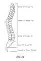
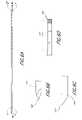
- FIG. 1Aprovides a lateral view of a normal spinal column.
- FIG. 1Billustrates examples of normal, degenerated, bulging, herniated, and thinning spinal discs.
- FIG. 1Cis a lateral view of the lumbar and sacral portion of the spinal column depicting the visualized anterior axial instrumentation/implant line (AAIIL) extending cephalad and axially from the anterior laminectomy site target point.
- AAIILanterior axial instrumentation/implant line
- FIG. 1Dis an illustration of an anterior target point on the sacrrum
- FIGS. 1E and 1Fare cross-sectional caudal views of a lumbar vertebrae depicting one and two trans sacral axial implants respectively within corresponding TASII bores formed in parallel with the visualized AAIIL of FIG. 1C .
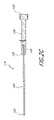
- FIGS. 2A and 2Bare a perspective view and a side cross-sectional view of one embodiment of a guide pin introducer, respectively, with pin and slot configuration.
- FIG. 2Cis a side cross-sectional view of one embodiment of a stylet with pin configuration.
- FIG. 2Dis a perspective view of one embodiment of a guide pin introducer-stylet-pin and slot configured assembly.
- FIG. 2Eis a side cross-sectional view of the assembly of FIG. 2D .
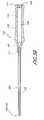
- FIG. 3Ais a perspective view of one embodiment of a guide pin introducer.
- FIG. 3Bis a side cross-sectional view of the guide pin introducer of FIG. 3A .
- FIG. 3Cis a side cross-sectional view of one embodiment of a stylet with multi-start thread configuration.
- FIG. 3Dis a perspective view of one embodiment of a guide pin introducer-stylet multi-start thread configured assembly.
- FIG. 3Eis a side cross-sectional view of the assembly of FIG. 3D .
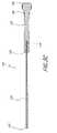
- FIGS. 4 and 5are lateral, partial cross-sectional views of the lumbar and sacral portion of the spine depicting delivery of the distal end of guide pin introducer-stylet-assembly to the anterior surface of the S 1 vertebral body.
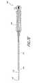
- FIG. 6Ais a side view of a guide pin detailing distal and proximal ends.
- FIG. 6Bis a side view of the distal end of one embodiment of a guide pin with a trocar tip configuration.
- FIG. 6Cis a side view of the distal end of an embodiment of a guide pin with a beveled tip configuration.
- FIG. 6Dis a side view of the proximal end of a preferred embodiment of a guide pin with a hex and flat configuration as means for tip alignment and axial and rotational locking.
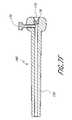
- FIG. 7Ais a cross sectional view of a guide pin-guide pin handle assembly.
- FIG. 7Bis a cross sectional view of a guide pin handle.
- FIG. 7Cdepicts the thumb screw, for locking the guide pin.
- FIG. 7Dillustrates a means for guide pin stop and steering.
- FIG. 7Edepicts a guide pin assembly inserted within an introducer illustrating the guide pin tip extending beyond the distal end of the introducer.
- FIG. 7Fis a cross section view illustrating a guide pin handle assembly, showing a releasable engagement means with the guide pin.
- FIG. 8Aillustrates a guide pin-guide pin extension assembly with a threaded engagement coupling.
- FIG. 8Bis a detailed view of guide pin-guide pin extension assembly with a threaded engagement coupling.
- FIG. 8Cillustrates a guide pin with a cross-sectional view of female thread engagement coupling.
- FIG. 8Dis an enlarged view of the female thread engagement coupling in FIG. 8C .
- FIG. 8Eillustrates the guide pin extension with a cross-sectional view of a male thread engagement coupling.
- FIG. 8Fis an enlarged view of the male thread engagement in FIG. 8E .
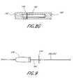
- FIG. 8Gillustrates an alternative embodiment of a guide pin-guide pin extension assembly with a friction fit engagement coupling.
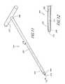
- FIG. 9is a side view of a slap hammer and a dilator handle on an extended guide pin.
- FIG. 10is an elevated view of three differently sized dilators.
- FIG. 11is a perspective view of one embodiment of a dilator.
- FIG. 12is a side cross-sectional view of the distal portion of the dilator in FIG. 11 .
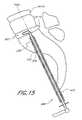
- FIG. 13Ais a perspective view of one embodiment of a large dilator with a dilator sheath.
- FIG. 13Bis a side cross-sectional view of a distal portion of the large dilator within the dilator sheath of FIG. 13A .
- FIG. 13Cis a perspective view of the sheath of the large dilator of FIG. 13A .
- FIG. 13Dis a perspective view of another embodiment of a large dilator sheath.
- FIG. 14is a side view of one embodiment of a twist drill.
- FIG. 15shows a cutter extending through a dilator sheath (docking cannula) in the L 5 -S 1 disc space.
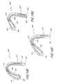
- FIG. 16Ais a perspective view of one embodiment of a cutter assembly that comprises a down-cutter.
- FIG. 16Bis a side cross-sectional view of the cutter assembly of FIG. 16A .
- FIG. 16Cis an exploded, perspective view of the distal portion of the cutter assembly of FIG. 16A .
- FIGS. 16D and 16Eare elevated views of one embodiment of a small down-cutter.
- FIG. 16Fis a cross sectional view of a proximal cutter blade arm ( 402 ′) for nucleectomy prior to a mobility preservation procedure taken along the line 16 F- 16 F in FIG. 16E .
- FIG. 16Gis a cross sectional view of a proximal cutter blade arm ( 402 ′) for nucleectomy prior to a fusion procedure taken along the line 16 F- 16 F in FIG. 16E .
- the inclined plane ( 421 )is a mirror image of that in of FIG. 16F .
- FIG. 16Hillustrates one embodiment of an upcutter ( 452 ).
- FIG. 16Iis a cross sectional view of a distal sleeve-shaft configuration showing a retraction stop mechanism for both a tissue cutter.
- FIG. 17Ais an exploded, perspective view of the distal portion of a cutter assembly that comprises a debulker.
- FIGS. 17B-17Care elevated views of the debulker of the cutter assembly of FIG. 17A .
- FIGS. 17D-17Eare elevated views of one embodiment of a large debulker.
- FIG. 18Ais an elevated view of one embodiment of a large teardrop debulker.
- FIG. 18Bis a rear elevational view of the portion teardrop debulker of FIG. 18A which attaches to the rotatable shaft.
- FIG. 18Cis another elevated view of a larger teardrop debulker of FIG. 18A .
- FIG. 18Dis an elevated view of one embodiment of a standard or medium size teardrop debulker.
- FIG. 18Eis a side isometric view of one embodiment of a large teardrop down-cutter.
- FIG. 18Fis a side isometric view of one embodiment of a medium teardrop down-cutter.
- FIG. 18Gis a side isometric view of one embodiment of a small teardrop down-cutter.
- FIG. 19Ais a side elevated perspective view of one embodiment of an extractor assembly unit.
- FIG. 19Bis a side elevated, partial cut-away view of the extractor assembly unit of FIG. 19A .
- FIG. 19Cis a side cross-sectional view of the extractor assembly unit of FIG. 19A .
- FIG. 19Dis a side elevated view of an extractor head prior to having its component wires unwound.
- FIG. 20illustrates the distal end of one embodiment of an extraction tool with tissue fragments within its wire strands.
- FIGS. 21A-Billustrate one embodiment of an extractor tool with its head extended into an exposed position and then pulled back into a delivery sleeve.
- FIGS. 21C-Dillustrate another embodiment of an extractor tool with its head in the extended position.
- FIGS. 22A-Billustrate another embodiment of an extraction tool.
- FIG. 23Ais a perspective view of one embodiment of an insertion tool assembly comprising a packing instrument and a delivery cannula.
- FIG. 23Billustrates engagement of the packing instrument with the delivery cannula, both from FIG. 23A .
- FIG. 23Cis perspective view of the packing instrument of FIG. 23A .
- FIG. 23Dis a perspective view of the delivery cannula of FIG. 23A .
- FIG. 24Ais a perspective view of one embodiment of a paste-inserter assembly.
- FIG. 24Bis a side cross-sectional view the assembly of FIG. 24A .
- FIG. 25Ais a perspective view of one embodiment of an allograft placement tool.
- FIG. 25Bis a side cross-sectional view of the tool of FIG. 25A .
- FIG. 25Cis a side cross-sectional view of the allograft tip of the tool of FIG. 25A .
- FIG. 26is a side elevated view of an exchange bushing.
- FIG. 27is a side view of one embodiment of an exchange system assembly comprising an exchange bushing and an exchange cannula.
- FIG. 28Ais a side elevated, cut-away view of one embodiment of an exchange cannula of FIG. 27 , in an open configuration.
- FIG. 28Bis a side elevated view of the exchange cannula of FIG. 27 , in a closed configuration.
- FIGS. 29A-Billustrate the use of the exchange system of FIGS. 26-28 to deliver a distraction device or an axial spinal implant of larger diameter than the dilater sheath.
- FIG. 30Ais side cross-sectional view of another embodiment of an exchange system assembly comprising an exchange bushing and an exchange tube.
- FIG. 30Bis a side cross-sectional view of the exchange bushing of FIG. 30A .
- FIG. 30Cis a side cross-sectional view of the exchange tube of FIG. 30A .
- FIG. 30Dis a perspective view of another embodiment of an exchange system comprising an exchange bushing and an exchange tube.
- FIG. 30Eis a bottom perspective view of the exchange system of FIG. 30D .
- FIG. 31is a perspective view of one embodiment of a temporary distraction rod and a tool that can be used to deliver or remove the rod from a treatment site.
- FIG. 32Ais a perspective, partial cut-away view of the temporary distraction rod of FIG. 32A and the distal portion of a tool that can be used to deliver the rod to the treatment site.
- FIG. 32Bis a perspective, partial cut-away view of the temporary distraction rod of FIG. 32A and the distal portion of a tool that can be used to remove the rod from the treatment site.
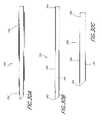
- FIG. 33Ais a perspective, partial cut-away view of the distal portion of one embodiment of a temporary distraction rod.
- FIG. 33Bis a side cross-sectional view of the rod distal portion of FIG. 33A .
- FIG. 33Cis a perspective view of the proximal portion of one embodiment of a temporary distraction rod.
- FIG. 33Dis another perspective view of the rod proximal portion of FIG. 33C .
- FIG. 33Eis a side cross-sectional view of the rod proximal portion of FIG. 33C .
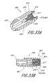
- FIG. 34Ais an exploded perspective view of one embodiment of a distraction-rod-assembly shown with the insertion tool.
- FIG. 34Bis a perspective view of the insertion tip of the assembly of FIG. 34A .
- FIG. 34Cis another perspective view of the insertion tip of the assembly of FIG. 34A .
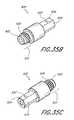
- FIG. 35Ais a perspective, exploded view of one embodiment of a temporary distraction-rod-assembly, shown with the removal tool.
- FIG. 35Bis a front perspective view of the tip of the removal tool assembly of FIG. 35A .
- FIG. 35Cis a rear perspective view of the tip of the removal tool assembly of FIG. 35A .
- the step of accessing the treatment siteincludes using fluoroscopic imaging to visually align one or more components of the instrumentation system via a percutaneous, anterior trans-sacral axial approach.
- the treatment siteincludes a spinal disc and the subsequent therapeutic procedure includes nucleectomy.
- the therapeutic procedureincludes immobilization devices to facilitate fusion; deployment of augmentation media; deployment of dynamic stabilization implants, or mobility devices to preserve or restore physiologic function.
- surgical tool sets and methods of using the tool setscan be used individually and/or in combination with each other.
- certain toolsfit over other tools, and therefore can be used over each other.
- the toolsfit through each other, and therefore can be used through one another.
- the access methods describedcan include the step of utilizing an anterior or posterior trans-sacral pathway.
- the therapies to the spinal discs and vertebral bodies described hereincan be conducted on one or more spinal discs or vertebral bodies.
- therapeutic proceduresare performed through or on at least one spinal disc and at least one vertebral body traversed by at least one working channel.
- FIGS. 1C-Dschematically illustrate the anterior trans-sacral axial spinal instrumentation/implant (TASII) approaches in relation to the lumbar region of the spinal column
- FIGS. 1E-Fillustrate the location of a TASII implant or pair of implants within an anterior TASII axial bore 152 or pair of TASII axial bores 22 1 , 22 2 , or 152 1 , 152 2
- Two TASII axial bores and spinal implants or rodsare shown in FIG. 1F to illustrate that a plurality, that is two or more, of the same may be formed and/or employed in side by side relation parallel with the anterior axial instrumentation/implant line (AAIIL).
- AAIILanterior axial instrumentation/implant line
- FIG. 1CThe lower regions of the spinal column comprising the coccyx, fused sacral vertebrae S 1 -S 5 forming the sacrum, and the lumbar vertebrae L 1 -L 5 described above are depicted in a lateral view in FIG. 1C .
- the series of adjacent vertebrae located within the human lumbar and sacral spinehave an anterior aspect, a posterior aspect and an axial aspect, and the lumbar vertebrae are separated by intact or damaged spinal discs labeled D 1 -D 5 in FIG. 1C .
- FIG. 1Ddepicts the anterior view of the sacrum and coccyx.
- the method and apparatus for forming an anterior TASII axial boreinitially involves accessing an anterior sacral position, e.g. an anterior target point at about the junction of S 1 and S 2 depicted in FIGS. 1C and 1D .
- One (or more) visualized, imaginary, axial instrumentation/implant lineextends cephalad and axially in the axial aspect through the series of adjacent vertebral bodies to be fused or otherwise treated, L 4 and L 5 in this illustrated example.
- the visualized AAIIL through L 4 , D 4 , L 5 and D 5extends relatively straight from the anterior target point along S 1 depicted in FIGS. 1C and 1D , but may be curved as to follow the curvature of the spinal column in the cephalad direction.
- trans-sacral axial spinal instrumentation/implantTASII
- anterior axial instrumentation/implant lineAAIIL
- TASIFtrans-sacral axial spinal instrumentation/fusion
- AAAFLanterior axial instrumentation/fusion line
- Elongated solid body membersin medical terminology include, for example, relatively stiff or flexible needles of small diameter typically used to penetrate tissue, wire stylets typically used within electrical medical leads or catheters to straighten, stiffen, or impart a curved shape to the catheter, guidewires that are used to traverse body vessel lumens and access remote points therein (certain hollow body guidewires have lumens for a number of uses), and obturators.
- Obturatorsare typically formed as rods provided in various diameters with blunt distal tips that can be manipulated to penetrate, separate or manipulate surrounding tissue without cutting or damaging the tissue.
- guide pincan include solid body members (e.g., guidewires) employed to perform the functions of guide pin delivery and guidance described herein, unless the exclusive use of a given one of such solid body members is explicitly stated.
- Such solid body memberscan be stiff or flexible and can include distal anchoring mechanisms, e.g., sharpened or beveled tips.
- Certain others of the surgical toolstake the form of hollow body, tubular members having lumens extending from proximal to distal ends thereof.
- Such hollow body, tubular memberscan take the form of medical catheters, medical cannulas, medical tubes, hollow needles, trocars, sheaths, or the like, or variations thereof.
- Such hollow body tubular members employed in various embodiments described hereincan be stiff or flexible and can include distal fixation mechanisms.
- anteriorrefers to in front of the spinal column (ventral) and posterior refers to behind the column (dorsal).
- proximalrefers the end or region that is closer to the surgeon or sacral region of the spine
- distalrefers to the end or region that is closer to the patient's head.
- a guide pin introducerthat can be used to facilitate access to the sacrum for delivery of at least one guide pin, which in turn serves as means over which other instruments of the surgical tools set can subsequently be delivered to target sites to perform their intended procedural functions, individually or in combination, over or through one another.
- the guide pin introducer 100comprises an introducer tube 102 and an introducer handle 110 .
- the introducer tube 102extends between a distal end 104 and a proximal end 106 , and defines an inner, tubular member lumen 108 .
- the length of the tube 102is typically in the range of about 4′′ (100 mm) to about 12′′ (310 mm), often about 5′′ (120 mm) to about 9′′ (230 mm). In one exemplary embodiment, the length of the tube 102 is approximately 7′′.
- the tube 102is preferably long enough to extend from a skin incision 190 near the paracoccygeal region, through the pre-sacral space, to an anterior target point 192 , as shown, for example, in FIGS. 4 and 5 .
- the inner diameter (I.D.) of the introducer tube 102is typically in the range of about 2 mm to about 5 mm, often about 3 mm to about 4 mm. In one exemplary embodiment, I.D. of the tube 102 is about 3.5 mm (0.13′′).
- the outer diameter (O.D.) of the tube 102is typically in the range of about 4 mm to about 7 mm, often about 5 mm to about 6 mm. In one exemplary embodiment, O.D. of the tube 102 is about 5.5 mm, with an I.D. dimensioned to slidably receive the distally located blunt tip 122 of the stylet 119 , as shown in FIGS. 2C-2E .
- the actual dimensions (e.g, length, inner diameter, outer diameter, etc.) of the tube 102 or any of the tools and components parts thereof described hereinwill depend in part on the nature of the treatment procedure and the physical characteristics of the patient, as well as the construction materials and intended functionality, as will be apparent to those of skill in the art.
- the edge 105 at the distal end 104 of the tube 102can comprise any number of configurations. In one embodiment, the edge 105 is at approximately a 90 degree angle relative to the longitudinal axis of the tube 102 . In another embodiment, the edge 105 is beveled at an angle relative to the longitudinal axis of the tube 102 . In one exemplary embodiment, the edge 105 is beveled at an angle of about 45 degrees.
- the tube 102can be made from any of a number of known suitable materials, such as, for example, stainless steel, Ni—Ti alloys, or structural polymeric materials, or composites thereof.
- the guide pin introducer tube 102serves as an enlarged diameter anterior tract sheath through which a guide pin, described in further detail below, can be introduced into the targeted site 192 .
- the introducer handle 110extends between a distal end 111 and a proximal end 113 , and defines a tubular member lumen 109 that is stepped or tapered toward the distal end 111 .
- the handle 110comprises a slot at its distal end which is dimensioned to receive a section of the tube 102 beginning at the tube proximal end 106 .
- the handle 110 and tube 102can be molded, machined or otherwise formed as an integral unit, or can be affixed to each other by any of a variety of known attachment means, such as, for example, thermal bonding, adhesives, or press fits.
- the introducer handle 110can be made from any of a number of known suitable materials, such as, for example, polysulfone, polyvinylidene fluoride, polyethylenes, PEEK, or composites thereof.
- introducer handle 110is fabricated from an injection-molded part, made from an acetal-based copolymer, such as DelrinTM obtained from the DuPont Company in Wilmington, Del., that is then machined with an I.D. of about 13 mm (0.50′′) and an O.D. of about 19 mm (0.75′′).
- the overall length of the guide pin introducer 100i.e., the length of the tube 102 and integral handle 110 , in total
- the overall length of the guide pin introducer 100is about 300 mm (11.95′′).
- a stylet with a blunt distal tipthat can inserted into the guide pin introducer described above to facilitate advancement of the guide pin introducer to the targeted site without causing damage to surrounding tissue.
- the stylet 119comprises an elongate body or rod 120 that extends between a distal end 122 and a proximal end 124 .
- the distal end 122 of the stylet rod 120preferably comprises a blunt tip, thereby preventing damage to surrounding soft tissue as the guide pin introducer-stylet-pin-slot configuration assembly 134 (the approach assembly), which comprises the introducer 100 and stylet 119 , described in further detail below, is advanced toward the targeted site, such as, for example, target point 192 , shown in FIG. 4B .
- a stylet 119can be used in combination with the guide pin introducer 100 by advancing the introducer-stylet-approach assembly 134 to the target area or point 192 .
- the length of the rod 120should be designed so that the stylet's blunt tip 122 extends beyond the distal end 104 of the guide pin introducer tube 102 .
- the rod 120has an O.D. of about 3.2 mm (0.125′′), which is less than the I.D. of the guide pin introducer 100 .
- the stylet rod 120can be made from any number of known suitable materials, such as, for example, stainless steel or the like.
- the stylet handle 126extends between a distal end 128 and a proximal end 130 , and comprises a distally located bore 129 to receive the section of the stylet rod 120 beginning at the rod proximal end 124 .
- the length of the stylet handle 126is typically in the range of about 3′′ (75 mm) to about 7′′ (175 mm), often about 4′′ (100 mm) to about 6′′ (150 mm).
- the O.D. of the handle 126is typically in the range of about 0.25′′ (6 mm) to about 0.75′′ (20 mm), and generally dimensioned to cooperate with the introducer handle 110 to form the introducer (approach) assembly 134 .
- the stylet handle 126has a diameter of about 12 mm to about 13 mm (e.g., about 0.50′′) at the distal end 128 that increases to about 20 mm (0.75′′) at the proximal end 130 .
- the length of the exposed rod 120 and narrow portion of the handle 126 togetheris about 300 mm (12′′) so that just the tip 122 of the stylet 119 will protrude from the distal end 104 of the introducer tube 102 upon assembly with the guide pin introducer 100 .
- the narrow portion of the stylet handle 126is configured to fit in a tubular member lumen 109 machined to receive it within the handle 110 of the guide pin introducer 100 .
- the stylet handle 126can be formed from any of a variety of materials, such as, for example, polymeric materials having desired properties (e.g., able to be machined or an injection-moldable polymer). Suitable materials include, but are not limited to polysulfone, polyvinilydene fluoride, acetal-copolymer; acrylic, high density polyethylene, low density polyethylene, nylon, polycarbonate, polypropylene, PVC, or the like, or combinations thereof.
- the guide pin introducer 100can be provided with a releasable interlock that prevents the blunt-tipped stylet 119 from retracting proximally within the lumens 108 , 109 of the cannulated guide pin introducer 100 , thereby maintaining the extension and exposure of the blunt tip 122 of the stylet 119 beyond the distal end 104 of the tube 102 as the introducer (approach) assembly 134 is advanced by the surgeon toward the target point 192 , optionally with the assistance of any known suitable visualization technique.
- the releasable lockmay comprise any of a variety of interference fit or friction fit surfaces carried by the stylet 119 for cooperating with a complementary structure on the introducer 100 . It will be noted that the releasable interlock can be on and between any of the approach assembly 134 components described herein.
- the releasable interlock of the introducer 100comprises a track 112 that is configured to accept the locking pin 139 of the stylet 119 , described in further detail below.
- the handle 110 of the introducer 100comprises an axially extending slot or track 112 , machined or otherwise formed through the wall of the handle 110 .
- Track 112is positioned with an open end beginning at the proximal end 113 and extends longitudinally in the distal direction along the handle 110 with a circumferentially extending notch 107 at the distal end of the track 112 .
- the stylet handle 126comprises a radially outwardly extending engagement structure such as a locking pin 139 that is configured to slideably fit within the track 112 of the introducer handle 110 .
- a locking pin 139advanced distally through the opening on the proximal end 113 of the introducer handle 110 , and along the axially extending track 112 .
- the locking pin 139serves as an interior stop or locking lug that releasably secures the stylet handle 126 within the introducer handle 110 .
- the locking pin 139comprises a 0.125′′ (3.2 mm) ⁇ 0.625′′ (15.8 mm) dowel pin.
- the approach assembly 134comprises the introducer 100 and the stylet 119 which are releasably interlocked to each other.
- the stylet handle 126 and the guide pin introducer 100can be mutually releasably engaged by the above-described locking pin 139 , other complementary surface structures, twist-lock mechanisms, such as in a preferred multi-start thread configuration shown in FIGS. 3A-3E ; a modified Luer lock, or any other known suitable mechanism that enables mechanical quick release (e.g., relative to another embodiment that uses a press-fit method of engagement of the respective handles).
- the guide pin introducer 100has internal threads 199 on the proximal end 113 that engage with external threads 198 on stylet handle 126 .
- Engagement and disengagement of the assembly 134 ′is by means of twist-lock.
- These quick release mechanismsfacilitate disengagement of the stylet handle 126 from the guide pin introducer handle 110 once the distal end 104 of the guide pin introducer tube 102 is brought into relatively close proximity to the target 192 .
- the stylet 119can be disengaged from the rest of the approach assembly 134 and removed from the patient's body.
- the stylet 119is inserted into the lumens 108 , 109 of the introducer tube 100 in a manner and configuration such that the blunt tip 122 extends and is preferably exposed from about 1 mm to about 2 mm beyond the distal end 104 of the guide pin introducer 100 .
- the blunt tip 122 of the stylet 119serves as a soft tissue dilator that assists in the safe and atraumatic positioning of the distal end 104 of the guide pin introducer tube 102 in close proximity to the anterior target site 192 .
- the stylet rod 120is inserted into the cylindrical polymeric handle 126 so that about 200 mm (about 7.76′′) of the rod 120 extends out of the handle 126 , into and through introducer tube 102 , and beyond the introducer tube distal end 104 , so that the distal end blunt tip 122 of the rod 120 is exposed at the distal most end of the approach or introducer assembly 134 .
- the spineis accessed via a small skin puncture 190 adjacent to the tip of the coccyx bone.
- the pre-sacral spaceis entered using any known suitable percutaneous technique.
- the introducer assembly 134with the stylet's blunt tip 122 serving as a dilator, is advanced through the paracoccygeal entry site. Once the tip 122 of the stylet 119 is advanced through the facial layer, the blunt tip 122 is positioned against the anterior face of the sacrum and advanced along the anterior surface of the sacrum to the desired position or targeted site 192 —here, the S 1 vertebral body.
- the distal portion of the approach assembly 134is advanced to the targeted site under fluoroscopic guidance, as is described in co-pending U.S. patent application Ser. No. 10/125,771, filed on Apr. 18, 2002, titled METHOD AND APPARATUS FOR SPINAL AUGMENTATION.
- the stylet 119is released and removed from the approach assembly 134 after the distal portion of the assembly 134 is advanced to the targeted site 192 , thereby leaving the distal portion of the introducer 100 at the targeted site, to preface the introduction of a guide pin through the introducter 100 to the targeted site 192 .
- a guide pinthat can be delivered to the targeted site through the use of a guide pin introducer, such as, for example, introducer 100 described above.
- the guide pin assembly 140has an elongate guide pin 142 that extends between a distal end 144 and a proximal end 146 .
- the guide pin assembly 140also has a sharp guide pin tip 145 at the distal end 144 and a preferably releasable handle 150 engaged at the proximal end 146 .
- the length of the guide pin 142is typically in the range of about 9′′ to about 15′′, often about 11′′ to about 13′′. In one exemplary embodiment, the length of the guide pin 142 is approximately 12′′. The length of the guide pin 142 is typically sufficiently long so that the tip 145 extends beyond the distal end 104 of the guide pin introducer tube 102 when the guide pin assembly 140 is inserted within the introducer 100 , as shown in FIG. 7E .
- the guide pin 142can be made from any of a number of suitable materials, such as, for example, stainless steel, NiTi alloys, or composites thereof.
- the guide pin 142is formed from substantially the same materials (e.g., stainless steel) as the stylet 119 and comprises a solid, elongated body 142 with an O.D. of between about 2.2 mm (0.090′′) to about 3.4 mm (0.13′′) and a length of about between about 300 mm (12.00′′)-600 mm (24′′).
- the guide pin tip 145is not blunt, and may be shaped according to one among various configurations.
- the guide pin tipis formed as a simple conical or two sided wedge pointed tip.
- the tip 145 ′is formed as a trocar tip that has a three-sided bevel at 15 degrees.
- the tip 145 ′′is formed as a beveled tip that has one side beveled at an angle. The angle can range, for example, from about 30 degrees to about 60 degrees relative to the longitudinal axis of the guide pin 142 .
- the selection of the tip 145 geometryis influenced by the need to initially tack the guide pin 142 into the target, such as, for example, the sacral face, without having the guide pin 142 slip off or slide up the target surface.
- Pointed tip geometriesenable the guide pin 142 to snag the sacral face, and thus eliminate “skidding” effects that may otherwise accompany tapping the target surface.
- the guide pin assembly 140comprises a guide pin handle 150 ′ that comprises a distal end 152 ′ and a proximal end 154 ′, and comprises a distally located lumen 175 to receive a section of the guide pin 142 ′ beginning at the guide pin proximal end 146 ′.
- the guide pin handle assembly 180 shown in FIG. 7Fcomprising the guide pin handle 150 and thumb/set screw element 170 is configured to align and releasably engage the guide pin 142 .
- a flat on guide pin 142see FIG.
- 6Dis positioned in a predetermined relationship to the bevel on guide pin tip 145 , so that when the guide pin is assembled and locked within the guide pin handle, wherein the thumb screw is advanced against the flat of the guide pin, this enables the clinician to determine, with reference to the thumb screw, visual or tactile indicia on the proximal handle which will indicate the rotational orientation of the beveled tip.
- the surgeonis able to determine, and adjust or “steer” the guide pin tip 145 position.
- the guide pin handle assembly 180comprises a metal hexagonal or square socket 178 within the insert 172 of the guide pin handle assembly 180 when mated with the proximal end of the guide pin hex 181 and flat 182 ( FIG. 6D ) it provides a positive stop precluding longitudinal and rotational motion of the guide pin 142 relative to the guide pin handle 150 .
- the handle 150has an O.D. of about 12 mm (0.50′′) on its distal end 152 , an O.D. of about 20 mm (0.75′′) on its proximal end 154 , and is approximately 100 mm (4′′) in length.
- a bore 175is formed in the distal end 152 extending substantially through the guide pin handel 150 , of about 3.5 mm (0.13′′) (i.e., substantially the same as the O.D. of the guide pin 142 ), into which the guide pin 142 can be releasably inserted.
- the guide pin handle 150can be formed from any of a variety of materials, such as, for example, polymeric materials having desired properties (e.g., able to be machined or an injection-moldable polymer). Suitable materials include but are not limited to sterilizable polymeric materials, e.g., polyvinilidine fluoride; polysulfone; acetal-copolymer; acrylic, high density polyethylene, low density polyethylene, nylon, polycarbonate, polypropylene, PVC, or the like, or combinations thereof.
- sterilizable polymeric materialse.g., polyvinilidine fluoride; polysulfone; acetal-copolymer; acrylic, high density polyethylene, low density polyethylene, nylon, polycarbonate, polypropylene, PVC, or the like, or combinations thereof.
- the guide pin handle 150is configured to be able to “steer” a guide pin 142 in the event that there is axial misalignment of the its after insertion.
- “steer”refers to an ability to manipulate by turning and make controlled positional adjustments of a guide pin 142 once it is tapped through the cortical bone of its anterior target 192 .
- the thumb/set screw 170( FIG. 7C ) serves as a point of reference to the tip 145 orientation and is particularly configured to mark the alignment of the guide pin's beveled tip 145 , as opposed to the face of the beveled plane.
- the guide pinWhen the guide pin is advanced it will tend to deviate in the direction of beveled tip, which is indicated, e.g., by the thumb screw. For example, if upon insertion the beveled plane of the tip 145 faces anterior, the guide pin 142 will track in the posterior direction when advanced.
- One exemplary method of useinvolves: advancing the distal portion of a delivery assembly 159 to the targeted site; removing the guide pin handle 150 ; removing the introducer 100 ; and leaving the guide pin 142 at, and attached to, the targeted site 192 .
- the guide pin handle 150 and the introducer 100are removed separately.
- the handle 150 and the introducer 100are removed together, leaving only the guide pin 142 in place.
- Disengagement of the guide pin handle 150 from the proximal end 146 of the guide pin 142enables extension of the guide pin's elongate body length through the addition of an extension 160 that can be attached to extend the length of the pins, thereby resulting in an extended guide pin, such as, for example, the long guide pin 164 ′′ of FIG. 8A which extends between a distal end 144 ′′ and a proximal end 146 ′′.
- a guide pinthat can be extended in length to facilitate the subsequent delivery and utilization of other access and preparation tools.
- the guide pin 142can be extended in length along its longitudinal axis via the addition of an extension 160 , which has a connector 162 on its distal end.
- the extension 160comprises an exchange pin
- the connector 162comprises a roll pin.
- the guide pin 142has a bore that is located at its proximal end 146 and that is dimensioned to receive a distal portion of the connector 162 .
- the extension 160has a bore that is located at its distal end and that is dimensioned to receive a proximal portion of the connector 162 .
- the guide pin 142 , extension 160 , and connector 162are releasably interconnected by any known suitable approach, such as, for example, an interference fit or friction fit or the like.
- the connector 162is fixedly secured to the distal end of the extension 160 and the connector is releasably secured to the proximal end of the guide pin 142 .
- the extended guide pin 164 ′′comprises a guide pin 142 ′′ and an extension 160 ′′ that are connected to each other through the use of a connector 165 , which protrudes from the distal end of the extension 160 ′′.
- the proximal end of the guide pin 142 ′′has a threaded bore 148 at its proximal end 146 ′′ that is dimensioned to receive the connector 165 .
- the connector 165comprises a threaded stud.
- the connector 165extends between a distal end 166 and a proximal end 167 and has a smaller outer diameter towards its distal end 166 , as compared to the larger outer diameter toward its proximal end 167 .
- the connector 165comprises screw threads 168 for releasably securing the extension 160 ′′ to the guide pin 142 ′′, which itself has a threaded bore 148 having threads 149 that is complementary to the threads 168 of the connector 165 .
- the length of the extended guide pinscan range from about 400 mm to about 800 mm, often about 500 mm to about 700 mm. In one embodiment, the length of pin 164 is about 600 mm (24.00′′).
- a guide pin-guide pin handle assembly 140is inserted into the cannulated guide pin introducer 100 .
- the guide pin 142is initially tapped into the sacrum it is in effect serving as a bone dilator.
- the guide pin introducer 100 and the guide pin handle 150are removed, to enable engagement of the guide pin 142 with the guide pin extension 160 .
- the subsequent componentscan be advanced over the extended pin 164 individually or in combination, over or through one another, to the targeted site 192 .
- the first tools in the sequence of instruments to be delivered over the guide pin 164are bone dilators, described in further detail below.
- certain materialswhich can enhance visualization of tools via radio-imaging (e.g., fluoroscopy).
- radio-imaginge.g., fluoroscopy
- materialsinclude stainless steel where tools or portions thereof comprise metal, and powders, such as barium sulfate, for components configured from polymeric materials, e.g., bushings, that may be inserted within the body cavity. It will be understood that such materials can be incorporated during the formation of certain metal or polymeric compounds comprised in the surgical tools sets and devices disclosed herein.
- dilation of soft tissueis common for certain surgeries, dilation of bone tissue is generally not a common technique for orthopedic procedures.
- dilating bone in the spineinvolves: widening the axial pathway or channel in preparation for subsequent treatments by compressing cancellous bone or cortical bone shell to the side rather than removal via cutting or coring such bone material.
- Compressionis usually a less traumatic procedure than coring with, for example, an electrically powered drill, as the latter may inadvertently cut or tear soft tissue, including nerves or blood vessels. Less bleeding of the bone occurs with dilation, which is an unanticipated benefit. It is believed that the compression of the bone by the dilator results in a tamponade effect so that the amount of bleeding from bone accompanying this procedure is reduced. Compression appears to afford stronger “anchoring”, for subsequent implants (e.g., implants with threading) within an inter-vertebral space. It is also possible that compression may have a long term beneficial impact via the initiation of subsequent osteogenic (bone growth) effects.
- bone dilatorsthat can be used to create and widen one or more channels in the vertebral bodies for the ensuing passage of other instruments and devices.
- the dilatorsare cannulated and can be delivered accurately to the target site, following removal of any preceding dilators, in succession one after another, each directly over the guide pin.
- the dilatorsare configured to pass concentrically over a previously delivered smaller dilator (i.e., a dilator having a relatively smaller O.D than the ID of successive dilators), without the extraction of the smaller dilator over the guide pin.
- the dilator 200comprises a cannulated dilator rod 202 extending between a distal end 204 and a proximal end 206 , and defines an inner lumen 212 .
- the dilator 200comprises a tapered dilator tip 208 with a distal end opening 214 at the distal end 204 and a handle 210 at the proximal end 206 .
- the length of the cannulated dilator 202is typically in the range of about 150 mm to about 450 mm, often about 250 mm to about 350 mm. In one exemplary embodiment, the length of the rod 202 is approximately 300 mm (12.00′′).
- the I.D. of the cannulated dilator rod 202is typically in the range of about 2.5 mm to about 4.5 mm, often about 3 mm to about 4 mm.
- the rod 202has an I.D. slightly larger than about 3.5 mm (i.e., greater that the O.D. of the extended guide pin 164 ) and an O.D. of about 6 mm.
- FIG. 10illustrates three bone dilators 200 1 , 200 2 , and 200 3 having O.D. of 6 mm, 8 mm, and 10 mm, respectively.
- the tapered dilator tip 208is usually tapered at about 5 to about 45 degrees from O.D. to I.D. In one embodiment, the tip 208 of the dilator 200 is tapered at approximately 8 degrees from O.D. to I.D. In another embodiment, the tip 208 is tapered at about 13 degrees from O.D. to I.D.
- the cannulated dilator rods 202can be made from any known suitable material, such as, for example, stainless steel, aluminum, or composites thereof.
- the dilator 200 and its component partsare machined from stainless steel tubing.
- each dilator 200has a handle 210 that is affixed to the dilator proximal end 206 .
- the handle 210is about 100 mm (4.00′′) long and is engaged (e.g., by welding; press fit, etc) in the middle to assure a secure fit with the rod.
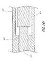
- a large dilator construct 199configured as a dilator sheath 220 and a dilator rod assembly 200 L that comprises a dilator shaft 202 L a dilator handle 210 L , and two pins 218 as engagement means for the construct 199
- the cannulated dilator shaft 202 Lextends between a distal end 204 L and a proximal end 206 L and defines an inner lumen 212 L .
- the shaft 202 Lcomprises a tapered tip 208 L with a distal end opening 214 L at the distal end 204 L .
- the dilator rod assembly 200 Lcomprises pins 218 extending out from the outer wall of the dilator shaft 202 L .
- the length of the cannulated dilator rod assembly 200 Lis typically in the range of about 8′′ to about 16′′, often about 11′′ to about 13′′. In one embodiment, length of the dilator rod assembly 200 L is approximately 300 mm (12.00′′). In one embodiment, the larger diameter proximal end 206 L of the dilator shaft 202 L is about 75 mm (3′′) in length while the overall length of the dilator rod assembly 200 L is about 300 mm. (12.00′′).
- the cannulated dilator shaft 202 Lhas two different outer diameters. More specifically, there is a smaller diameter section of the dilator shaft 202 L configured to be covered by the sheath 220 .
- the O.Ds.are typically in the range of about 5 mm to about 12 mm, often about 6 mm to about 11 mm.
- the dilator shaft 202 Lhas a smaller O.D. of about 9 mm (0.35′′) and a larger O.D. of about 10 mm.
- the I.D. of the dilator shaft 202 Lis typically in the range of about 2.5 mm to about 4.5 mm, often about 3 mm to about 4 mm.
- the tapered dilator tip 208 Lis usually tapered at about 5 to about 45 degrees from O.D. to I.D. In one embodiment, the tip 208 L of the dilator shaft 202 L is tapered at about 13 degrees from O.D. to I.D. In one preferred embodiment, this taper of tip 208 L is substantially the same as the taper of the tip 226 at the distal end 222 of the dilator sheath 220 .
- the sheath 220comprises a sheath tube 221 that extends between a distal end 222 and a proximal end 224 , and is configured to be releasably attachable to the dilator rod assembly 200 L .
- the sheath tube 221comprises a tip 226 at the distal end 222 and two tracks (one shown) 229 machined into the wall of the tube 221 , that is positioned to begin at the proximal end 224 and extend longitudinally along the sheath tube 221 with a slight circumferential notch at the distal end of the track 229 .
- the track 229accepts the pin 218 mounted on the dilator shaft 202 L , thereby providing a releasable interlock of the dilator shaft 202 L with the sheath 220 .
- the large dilator construct 199comprises any known suitable releasable lock comprising any of a variety of interference fit or friction fit surfaces carried by the dilator shaft 202 L for cooperating with a complementary structure on the sheath 220 .
- the large dilator construct 199comprises two tracks 229 and two locking lugs 218 . In another embodiment, the large dilator construct 199 comprises one track 229 and one pin 218 .
- Both the dilator shaft 202 L , the sheath 220 , and their respective component partscan be made from any known suitable material, such as, for example, stainless steel, aluminum, or composites thereof.
- the sheath 220is preferably fabricated from a material of sufficient stiffness to maintain its structural integrity when other access and preparation tools are subsequently introduced and utilized through the sheath cannula.
- the distal end 222 of the sheath 220is beveled to match the taper of the dilator tip 208 L of the large dilator rod assembly 200 L (e.g., 10 mm dilator), thereby facilitating insertion of the rod 202 L into the sheath 220 .
- the large dilator rod assembly 200 Le.g. 10 mm dilator
- the length of the sheath 220is typically in the range of about 7′′ to about 10′′, often about 8′′ to about 9′′. In one embodiment, the sheath 220 is approximately 200 mm (8.5′′) in length.
- the wall thickness of the sheath 220is typically in the range of about 0.005′′ to about 0.040′′, often about 0.008′′ to about 0.030′′. In one embodiment, the sheath 220 has an I.D. of about 9 mm (0.35′′) and an O.D. of about 10.5 mm (0.413′′).
- the actual dimensions of the large dilator rod assembly 200 L and its componentswill depend in part on the nature of the treatment procedure and the anatomical characteristics of the patient.
- the O.D.is about 9.5 mm (0.375′′) for a sheath 220 used in treating relatively smaller patients, while the O.D. for the same is about 10.5 mm. (0.413′′) for relatively larger patients.
- a distal end taper 228as a transition to enable use of a smaller distal OD dilator sheath 220 (e.g., 0.375′′) with a sturdier proximal wall thickness, where clinically appropriate.
- the sheath 220 , 220 ′has a beveled tip 226 at the distal end 222 , which facilitates docking of the sheath 220 , 220 ′ to the targeted site 192 , i.e., the anterior surface of the S 1 vertebral body.
- the large dilator rod assembly 200 Lis preferably releasably interlocked to the proximal end 224 of the dilator sheath 220 and is preferably capable of being released and removed thereby facilitating the withdrawal of the large dilator rod assembly 200 L while leaving the sheath 220 to serve as a working cannula into the targeted site, such as, for example, the anterior surface of the S 1 vertebral body.
- the dilator 200is tapped with a cannulated slap hammer 230 that slides onto the extended guide pin 164 . Successive movements distally and proximally over the extended guide pin 164 that repeatedly tap against the dilator handle 210 will to advance the dilator, longitudinally, into the sacrum.
- the hammer 230has a flat on it to give another hammering surface, as well as for ease of use, where the additional flat prevents the hammer from rolling off of the table.
- the use of the slap hammer 230 engaged on the extended guide pin 164as opposed for example, to the use of an unengaged mallet in “free space” on the proximal end 206 of a dilator 200 , enables the surgeon to focus his attention on the visualization monitor while simultaneously tapping and dilating.
- the axial alignment of the slap hammer 230 resulting from its use in combination with the extended guide pin 164is advantageous in that it transfers force solely in the longitudinal direction, which precludes misshapen pathways or misalignment of subsequently introduced tools.
- the hammer 230has a length of about 4′′ (100 mm).
- the I.D. of the cannulated hammer 230is configured to slide over the guide pin.
- the hammerhas a lumen ID of about 3.5 mm (0.13′′).
- the cannulated slap hammer 230can be made from any known suitable material, such as, for example, stainless steel or the like.
- a series of bone dilators 200 1 , 200 2 , and 200 3having O.D. of 6 mm, 8 mm, and 10 mm, respectively, are advanced directly over the guide wire 164 , and tapped with a slap hammer 230 to progressively widen the intervertebral channel in a stepwise manner.
- the last and largest dilator 200 L( 200 3 in the present embodiment) is assembled with a sheath 220 .
- the dilator 200 Lcan be inserted as a preface to the subsequent introduction of successive instruments in the surgical tools sets described herein.
- the large dilator sheath 220is preferably left behind to serve as a protected portal to the target location.
- the dilators and sheathsare coated with a surfactant, hydrophilic hydrogel, or the like to facilitate passage of surgical tools and/or implants through the sheath 220 .
- the surgical tools and/or implants inserted into the sheath 220are coated with a surfactant, hydrophilic hydrogel, or the like.
- twist drillsthat can be used to extend the working channel within the spine, such as, for example, a channel that extends cephalad from the anterior surface of the S 1 vertebral body.
- a twist drill with handle 300that a configured as a twist drill 301 having a distal end 302 comprising a fluted section 306 with helical flutes 308 and a proximal end 304 , and a handle 310 engaged at the proximal end 304 of the twist drill 301 .
- the helical flutes 308facilitate boring as the handle 310 is turned in the appropriate direction—here, clockwise to advance the twist drill 301 distally into the working channel.
- the twist drill with handle 300is typically fabricated from hardened stainless steel or the like.
- the length of the twist drill with handle 300typically ranges from about 11′′ (275 mm) to about 13′′ 330 mm. In one embodiment, the twist drill with handle 300 is approximately 300 mm (12.00′′) long.
- the twist drill with handle 300typically ranges in diameter from about 5 mm (0.20′′) to about 13 mm (0.50′′). In one embodiment, the twist drill with handle 300 has a diameter of about 9 mm.
- the twist drill with handle 300is used to extend the working channel in the spine to the treatment area (e.g., a disc space) after bone dilators are used to expand the diameter of the proximal portion or entry/targeted site 192 of the working channel.
- the treatment areae.g., a disc space
- a twist drill with handle 300having an O.D. of about 9 mm and is inserted into the lumen at the proximal end 224 of the dilator sheaths 220 or 220 ′, each of which is used as a protected portal to the sacrum.
- the twist drill with handle 300is advanced by turning the handle 310 at the proximal end 304 of the twist drill 301 so that the helical flutes 308 at the distal end 302 of the twist drill 301 progressively bore into and penetrate through the superior S 1 bone end plate and into the L 5 -S 1 disc space.
- the twist drill with handle 300can again be used to penetrate the L 5 inferior bone end plate and vertebral body, prior to the removal of the dilator sheath 220 or 220 ′, using, for example, a 6 mm or a 7.5 mm twist drill with handle 300 as needed based on the patient's anatomy.
- the twist drill with handle 300is used to drill about halfway into the depth of the L 5 vertebral body in preparation for subsequent anchoring of implants, or through the vertebral body to gain axial access to more distal inter-vertebral disc spaces, e.g., L 4 -L 5 , for therapeutic procedures.
- the twist drill unitcomprises a bushing portion configured to compensate for the (mismatch) differences between the I.D. of the dilator sheath 220 or 220 ′ and the O.D. of the twist drill with handle 300 , thereby precluding “wobble” in the disc space en route to the L 5 target, and thus enabling on-center axial alignment and use.
- the bushing portionis preferably located on the twist drill 301 near the proximal end 304 that is sufficiently distant from the distal end 302 so that it remains within the confines of the dilator sheath 220 or 220 ′ during operation of the tool for its intended purpose.
- the bushing portionis made from a polymer, such as, for example, DelrinTM, PTFE, PVDF, or the like.
- the bushingis integral with the twist drill 301 , i.e., formed from the same rod blank.
- twist drill configuration, mode of delivery, and use at the target siteare no longer dependent on electrical or motorized drilling, thereby eliminating the risks of tissue damage associated with electric drill slippage and recoil.
- nucleectomy and cutting tools and techniqueshaving advantages over conventional cutting tools and techniques.
- Certain conventional proceduresrely on brute force to scrape, tear or break away the material.
- rongeurs, or “pliers-like” devicesare often utilized to reach in through an access hole cut into the annulus, grab an amount of nucleus tissue and then to rip it out.
- curettes or various flat blades with sharpened edgesare inserted and scrapped against the bone in an attempt to separate the nucleus from the bone.
- Another conventional approachinvolves using enzymes, such as, for example, chemopapain, to chemically dissolve or break-down the nuclear tissue.
- enzymessuch as, for example, chemopapain
- the apparatuses and methods described hereinare not reliant on the application of strength and high forces and are designed be more effective in complete removal of tissue and clean preparation of any bone surfaces.
- one or more nucleectomiescan be performed extending into successively cephalad intervertebral disc spaces.
- a disc recess 354 ′is depicted in disc L 4 -L 5
- a wide variety of cutter blade and edge configurations as bore enlarging meanscan be employed to perform nucleectomies of the L 5 -S 1 354 , and L 4 -L 5 354 ′ disc spaces, wherein the cutter means are delivered and operated through the anterior TASII axial bore(s). Certain of these methods are described in further detail in U.S. patent application Ser. No. 09/710,369, the content of which is incorporated in its entirety into this disclosure by reference.
- a nucleectomy instrument 400is inserted through the axially aligned anterior tract 372 defined by the lumen of the dilator sheath 220 and the TASII axial bore 370 .
- the nucleectomy instrument 400comprises a cutting blade (e.g., cutter blade 453 which refers collectively to any blade configuration) which is remotely manipulatable, i.e., a retracted cutter blade 453 is first advanced through the TASII axial bore 370 and then extended laterally into the nucleus of the spinal disc. More specifically, the cutting blade 453 is mounted into an extendible or steerable distal end section 382 of nucleectomy instrument, i.e. cutter assembly 400 extending through the TASII axial bore 370 and anterior tract 372 .
- a cutting bladee.g., cutter blade 453 which refers collectively to any blade configuration
- the cutter assembly 400 , cutter blade 454 and cutter assembly shaft 410are shown schematically in FIGS. 16-18 and not necessarily to scale to one another or to the TASII axial bore 370 .
- surgical cuttersthat can be used to perform nucleectomy via insertion into a disc space to excise, fragment and otherwise loosen nucleus pulposus and cartilage from endplates from within the disc cavity and from inferior and superior bone end plate surfaces.
- the cutters described hereinrepresent a significant advance to current clinical techniques for access and preparation of intervertebral bodies for the subsequent insertion of therapeutic devices, such as prosthetic nucleus and fusion implants, and in particular for axially aligned implants, or for insertion of therapeutic materials, e.g., for osteogenesis, spinal arthroplasty, or annuloplasty.
- the cutter assembly 400comprises: a cutter shaft 410 extending between a distal end 412 and a proximal end 414 ; a cutter blade 453 at the distal end 412 ; a handle 416 at the proximal end 414 ; a cutter sheath 430 placed concentrically over the shaft 410 ; and a shaft sleeve 418 at the distal end 412 .
- the cutter components and structures described hereinare suitable for the assembly and application of cutter assemblies that comprise, for example, up-cutters 452 , debulkers 450 , down-cutters 454 , or the like, or variations thereof.
- the cuttercomprises a down-cutter 454 .
- the cuttercomprises an up-cutter 452 (see FIG. 16H )
- the cuttercomprises a debulker 450 (see FIGS. 17A-E ).
- the longitudinal portion 406 of the cutter blade(e.g., debulker 450 , up-cutter 452 , or down-cutter 454 ) is placed into a slot 413 near the distal end 412 of the shaft 410 .
- the cutter blade hole 407is aligned with a strategically placed cutter shaft hole 411 within the shaft slot 413 .
- the shaft slot 413is dimensioned to accommodate a cutter blade 453 such as, for example, a debulker 450 ( 17 A), an up-cutter 452 , a down-cutter 454 ( 16 C), or the like, or variations thereof.
- the width of the slot 413is approximately the same as the width of the longitudinal portion 406 of the cutter blade 453 .
- the curvature at the distal end of the slot 413accommodates the curvature of the cutter blade 453 between the longitudinal portion 406 and the laterally extending portion of the blade arm 402 (which defines the reach or throw of the cutter blade 453 ).
- the slot 413provides torsional support to the cutter blade arm 402 while the curvature at the distal end of the slot 413 provides axial support to the cutter blade arm 402 , necessary, in conjunction with cutter blade edge geometries (described in detail below; see FIGS. 16D-6H and 17 B- 17 E, and 18 A- 18 F) to the cutting effectiveness of the cutter blade 453 .
- a shaft sleeve 418may be placed over the assembly shown in FIGS. 16C and 17A comprising the shaft 410 and the cutter blade 453 .
- the shaft sleeve 418 when pinnedeffectively serves to align and fix the shaft 410 and the longitudinal portion 406 of the cutter blade 453 . While any of variety of other fastening techniques may also be used, the preferred pin technique is described below.
- the shaft sleeve 418comprises a strategically placed shaft sleeve hole 419 that aligns with the cutter shaft hole 411 of the shaft slot 413 and the cutter blade hole 407 .
- the sleeve 418can be securedly fixed to the rest of the assembly by inserting a cross pin 409 through the shaft sleeve 418 and the longitudinal portion 406 of the cutter blade 453 into the shaft 410 .
- the cross pin 409 that fixes the cutter blade 453 to the shaft 410is approximately 0.06′′ in diameter.
- the rest of the assembly 400 componentscan be fixedly secured to each other using any known suitable fixation mechanisms, as described in further detail below.
- the cutter blade 453(as shown, a down-cutter 454 ) comprises a blade arm 402 and a longitudinally-extending portion 406 .
- the blade arm 402begins from the proximally-located, longitudinally-extending portion 406 , and extends laterally to comprise any number of suitable shapes or configurations, such as, for example, a “J” shape or “S” shape, as shown. It is understood that in the context of the present invention, configurations of the types as just described may comprise a plurality of cutter blade arms 402 .
- the cutter blade 453comprises a “teardrop” shape ( 460 , 460 ′, 490 , 490 ′, 490 ′′) shown in FIGS. 18A-18G .
- the cutter blades 453generally comprise at least one sharpened cutter blade edge 401 (collective).
- the cutter blade arms 402 (collective) of the down-cutters 454have three cutter blade edges 401 including cutter blade arms 402 ′ (proximal), and 402 ′′ (distal) separated lateral bend 403 .
- the cutter blade edgesmay be continuous with each other around the lateral bend 403 or may be interrupted.
- the illustrated blade edges 401are illustrated on a leading surface 405 of the cutter blade arm 402 .
- a trailing surface 415is illustrated as a blunt side, without a sharpened cutter blade edge 401 .
- the cutter blade 454is considered to be single-sided in this regard.
- the single-sided cutter blade arms 402cut when turned in a clockwise manner but do not cut when rotated in a counter-clockwise direction. The direction of the rotation (clockwise or counterclockwise) is determined from a perspective that is proximal relative to the distally-located cutter.
- the cutter blade arms 402have cutter blade edges 401 on both the leading surface 405 and trailing surface 415 of the cutter blade arms 402 , so that cutting can be accomplished with this double-sided cutter blade arms 402 by means of either clockwise or counterclockwise rotation.
- all of the cutter blade edges 401 disclosed hereinmay be optimally configured for preparing an intervertebral motion segment for either a subsequent fusion procedure or a subsequent procedure in which mobility of the intervertebral motion is to be preserved. More specifically, for nucleectomies preceding fusion procedures, cutter blade edges 401 —regardless of cutter blade arm 402 configuration—will contact the spinal disc inferior or superior endplates, while for mobility procedures, the cutter blade edges 401 will be spaced apart from the spinal disc endplates.
- FIG. 16Gthere is illustrated a cross-sectional view through cutter blade arm 402 of the cutter blade 454 illustrated in FIG. 16E .
- a leading side 405is provided with a sharpened edge 420 fabricated by means of cutting, grinding or other manufacturing technique.
- the sharpened edge 420is formed at the intersection of the declined face 421 and the surface 424 of the cutter blade arm 402 ′ and 402 ′′.
- This cutter blade 454 configurationis optimized for use against an inferior endplate in preparation for a fusion procedure.
- the sharpened edge 420 on leading surface 405will scrape against said endplate. This can be used to scrape away the cartilaginous endplate and roughen the vascularized vertebral body so as to cause bleeding, which is desirable in order to facilitate bone growth and achieve fusion of the vertebral bodies that are superior and inferior to the spinal disc being treated.
- the sharpened edge 420 ′is desirably positioned at the intersection of the inclined face 421 and the surface 424 , such as by mirroring the angle of inclination of the declined face 421 .
- the sharpened edge 420 ′will be spaced apart from the inferior endplate of the spinal disc by a distance which is equal to the thickness of the proximal cutter blade arm 402 ′, thereby minimizing the chance of the bone bleeding, that would promote unwanted fusion.
- FIG. 16Fthe mirrored blade of proximal cutter blade arm 402 ′ is shown in FIG. 16F and FIG. 16G as distal cutter blade arm 402 ′′.
- a sharpened edgemay alternatively be positioned partway between the proximal surface 422 and the distal surface 424 , such as providing a first and second inclined face on the leading surface 405 , which intersect at a sharpened edge 420 .
- the sharpened edge 420is preferably spaced apart from the surface of the cutter adapted for sliding contact with a boney end plate.
- the sharpened edge 420may optimally be spaced apart from the bone contacting surface by the full thickness of the cutter blade, as discussed above, a sharpened edge 420 may be positioned in-between the proximal surface 422 and the distal surface 424 by a sufficient distance to prevent injury to the bone.
- the distal and proximal orientation of the sharpened edge 420 described abovemay be mirrored on a given cutter blade, depending upon whether the cutter is intended to be placed in sliding contact with an inferior or superior spinal disc endplate, as will be apparent to those of skill in the art in view of the disclosure herein. Again, the foregoing sharpened edge orientation may be applied to any of the cutter configurations disclosed herein.
- the cutter of the assembly 400comprises an up-cutter blade 452 .
- the up-cutter blade 452generally comprises a cutter blade arm 402 and a longitudinally extending base portion 406 .
- the cutter blade arm 402begins from a proximally located, longitudinally extending base portion 406 that extends generally distally and inclines laterally outwardly to a radial limit 404 .
- the arm 402curves to form a proximally facing concavity with a distal limit.
- the cuttermay comprise any number of suitable shapes or configurations, such as, for example, a “J” or question mark shape. In another embodiment, described below, the cutter comprises a “teardrop” shape.
- the down-cutters 454 and up-cutters 452have single-sided blade arms 402 that are bent at an angle from between about 40 degrees to about 140 degrees relative to the longitudinally extending portion 406 .
- the blade arms 402can optionally be canted between about 5 to about 25 degrees, preferably about 15 degrees, so that the cutting edge is rotated radially outwardly relative to the trailing edge.
- the blades arms 402 of the up-cutters 452 and down-cutters 454are preferably angled vertically steeper relative to the longitudinal axes of the shafts to which they are affixed, as compared to those of debulkers 450 , described in further detail below.
- the tilt of the blade arm 402 in the proximal direction in FIGS. 16D , 16 E and 16 His configured to allow for maximum engagement of the blade cutting edge with the distally facing surface of the bone end plate, while severing nucleus material.
- an angle less than about 90 degrees relative to the axis of the shaft 410generally would not enable adequate engagement of the blade cutting edge(s) 401 with the superior bone end plate.
- an angle greater than about 90 degrees relative to the axis of the shaft 410generally would not facilitate adequate engagement of the blade cutting edge with the inferior bone end plate, and a blade arm 402 at about a 40 degree angle of tilt of the blade arm 402 operates preferably (is “vertically steeper”) than one at 70 degrees.
- blade arm throwi.e., the reach of the blade arm 402 is measured from the central longitudinal axis of the cutter shaft 410 radially outward to its radial limit 404 (FIG. 16 H).
- blade arm throwrefers to the radius of the circle cut by a full revolution of the blade arm.
- the blade arm 402 throware generally within the range of from about 6 mm to about 18 mm. In one embodiment, the blade arm throw of the cutters 452 , 454 are about 12 mm.
- the cutter blade of the assembly 400comprises a debulker 450
- Up-cutters 452 and down-cutters 454may not be ideal initiators of nucleus tissue fragmentation.
- their blade arms 402 and cutting edges 401do not easily bend or sweep without space, particularly in terms of angles, having first been created by one or more debulkers 450 .
- a debulker 450comprises a cutter blade arm 402 that begins from a proximally-located, longitudinally-extending base portion 406 and extends laterally to comprise any number of suitable shapes or configurations, such as, for example, a “J” or “U” shape, as shown.
- the debulker 450comprises a shorter throw than the cutter blade 454 , which allows debulkers 450 to retain their shape better than cutters with longer arms upon initial entry into the disc space, providing improved engagement of effective cutting edge surface with nucleus material.
- FIGS. 17B-Cillustrated one embodiment of a relatively smaller sized debulker 450 .
- FIGS. 17D-Eshow one embodiment of a debulker 450 ′ having a greater cutting radius.
- the blade arm 402 configuration of a debulker 450resembles a “J” in shape.
- the functional advantage of such blade vertical elements in the “J” shapeis the increased efficiency of cutting per unit of throw or the increased cutting edge surface contact with the material to be fragmented.
- the debulkers 450 , 450 ′have single-sided blades (i.e., cutter blade edges 401 on one of the cutter lateral sides). In another embodiment, not illustrated, the debulkers 450 have double-sided blades (i.e., blade edges on both of the cutter lateral edges), which enables bi-directional cutting when the cutter handle 416 is manipulated to rotate the blade arm 402 .
- debulkers 500 with shorter arm lengths, and hence shorter “throws” in terms of circumferential cutting diameterare first introduced through the large dilator sheath 220 into the disc space and used to fragment the tissue within the disc space.
- one or more down-cutters, up-cutters, or the like, or variations thereofare used to further fragment the tissue within the disc space.
- cuttersthat comprise a closed loop such as a “teardrop” shape configuration, which provides more cutter rigidity and reduces the risk of fracture of the cutters during use (e.g., when a leading cutting edge of the cutter becomes embedded in bone during use).
- a closed loopsuch as a “teardrop” shape configuration
- the any of the cutters (e.g., down-cutters, up-cutters, debulkers) described hereincan comprise a “teardrop” or other closed loop shape.
- Cutterse.g., debulkers, up-cutters, down-cutters, etc.
- Cuttersthat comprise a closed loop generally provide a more robust and overall more efficient cutting device that can be used for any number of surgical procedures, such as, for example, nucleectomy.
- Closed loop cuttersmay have a variety of advantages over cutters having only a single attachment point to the rotatable support.
- the closed loop shapeallows for two fully supported cutting edges (e.g., top and bottom) on any given lateral side of the cutter.
- the closed loop shapealso allows for side or end edges in the curve where the blade or cutter arm doubles back on itself.
- a standard size closed loop debulker 460With reference to embodiment shown in FIGS. 18A-B , there is provided a standard size closed loop debulker 460 .
- the cutter arm 462 of the closed loop debulker 460doubles back upon itself to form a distal segment 470 and a proximal segment 468 .
- Both the distal segment 470 and proximal segment 468are secured to the rotatable shaft 410 , resulting in the distribution of any stress in the arm 462 over two segments rather than over a single segment arm.
- the distributed stresscan result from the torque of turning the shaft 410 or the resistance of the disc material on the blade(s) 461 .
- the arm 462 of the closed loop cutterbegins from a proximally located end 480 , extends distally to provide an attachment surface and then laterally outward to form the lower segment 468 .
- the arm 462then doubles back at juncture 482 , the location of which defines the cutting radius.
- the arm 462then extends laterally inward, turns, and then proximally toward proximal end 484 , to provide an attachment surface.
- the proximal and distal segments 468 , 470each comprise a sharp edge 461 .
- the distal segment 470comprises an attachment structure such as a slot 472 near the proximally located end 484 .
- the lower segment 468also comprises an attachment structure such as a cutter blade hole 467 near the proximally located end 480 .
- the shaft slot 472enables end 470 to slide relative to the cross pin 409 during extension and retraction of the cutter blade (e.g., 460 or 490 ) of the assembly 400 .
- a large teardrop shaped debulker 460 ′having a longer laterally extending portion and longer blades 461 ′, relative to the debulker 460 of FIGS. 18A-B .
- a longer teardrop configurationgenerally allows for further reach than smaller ones.
- the cutter blades 460 , 460 ′, 490 , 490 ′ of FIG. 18A-FIG . 18 Dwhen rotated through a complete revolution will cut a transversely circular cavity having a diameter within the range of from about 10 mm to about 30 mm,
- the proximal segment 468 , 468 ′ and distal segment 470 , 470 ′extend radially outwardly from the axis of rotation generally in parallel with each other.
- alternative configurationsmay also be used, such as by imparting curvature to one or both of the proximal segment 468 and distal segment 470 .
- One or both of the segmentsmay be provided with a curve having a concavity facing in the distal direction; a concavity facing in the proximal direction, or concavities opposite to each other, depending upon the desired clinical result.
- the cutter blade arm 462 formed by the proximal segment 468 and distal segment 470extends radially outwardly at approximately a 90 degree angle from the longitudinal axis of the rotatable shaft 410 .
- the cutter blade arm 462may alternatively be inclined in either a proximal or distal direction (not shown) depending upon the desired performance, and, for example, whether the cutter is intended to operate against an inferior or superior spinal disc endplate.
- the cutter blade arm 462may incline in a distal direction or a proximal direction by as much as 45 degrees away from the perpendicular.
- teardrop shaped down-cutters 490 , 490 ′, 490 ′′having large, medium, and small sizes, respectively.
- the length of the teardrop shaped cuttersvaries in the range between about 0.25′′ to about 1.00′′.
- These arcuate cutterscan extend linearly within a deployment sheath and “curve” as they are advanced distally out of the sheath into the disc space, instead of extending axially until fully deployed from the sheath and then “flopping over” which requires a lateral advance through the nucleus material as well as sufficient axial clearance to allow deployment within the disc.
- the cutterpreferably has a low profile during extension, use, and retraction.
- Straight bladed cutterswill extend linearly in the axial direction of the deployment sheath during extension and long versions may actually hit the upper endplate, causing the cutter to get stuck or inhibiting complete deployment.
- the double-back structure of the teardrop down-cutter 490begins from a proximally located end 480 , extends distally along the lower segment 468 , extends laterally outward and downward (i.e., proximally) to form a proximally facing concavity, along the lower segment 468 , doubles back at juncture 482 , extends laterally inward and upward (i.e., distally), and then extends proximally along the upper segment 470 toward proximally located end 484 .
- At least one and preferably both of lower and upper segments 468 , 470comprise a blade 461 .
- the upper segment 470comprises a slot 472 near the proximally located end 484 .
- the lower segment 468comprises a cutter blade hole (not shown) near the proximally located 480 .
- the shaft slot 472enables end 484 to slide relative to the cross pin 409 during extension and retraction of the cutter blade (e.g., 490 , 490 ′, 490 ′′) of the assembly 400 .
- the separation distance between the first and second cutting edgesis a controllable variable in manufactureine (e.g., predetermined during cutter blade formation, i.e., heat treatment of the pinned Nitinol shape memory alloy) and varies from about 2 mm to about 8 mm, and, often is about 3 mm to about 4 mm.
- the maximum separation 483 in the illustrated embodimentis located within about the radially outwardly most one third of the total blade length. Alternatively, the maximum separation 483 may be positioned within the radially inwardly most third of the blade length, or within a central region of the blade length, depending upon the desired deployment and cutting characteristics.
- the blade arms 402 and the cutter blades 453in general can be formed from strip material that is preferably a shape memory alloy in its austenitic phase at room and body temperature and that ranges in width from about 0.10-0.20′′ and in thickness from about 0.015-0.050′′.
- Blade arms 402 formed in accordance with the present embodimentare generally able to be flexed in excess of 100 cycles without significant shape loss, and twisted more than 1 and 1 ⁇ 2full turns (about 540 degrees) without breakage.
- the cutting blade 453 and cutter blade edge 401is formed from a super-elastic, shape memory metal alloy that preferably exhibits biocompatibility and substantial shape recovery when strained to 12%.
- a super-elastic, shape memory metal alloythat preferably exhibits biocompatibility and substantial shape recovery when strained to 12%.
- One known suitable material that approximates the preferred biomechanical specifications for cutter blades 453 and cutter blade edges 401 and blade arms 402is an alloy of nickel and titanium (e.g., Ni 56 ⁇ Ti 45 and other alloying elements, by weight), such as, for example, Nitinol strip material #SE508, available from Nitinol Devices and Components, Inc. in Fremont, Calif. This material exhibits substantially full shape recovery (i.e., recovered elongation when strained from about 6%-10%, which is a factor of ten better than the recovered elongation at these strain levels of stainless steel).
- the shape and length of the formed cutter blade 453in general varies for the different cutting modes.
- the shape memory materialcan be formed into the desired cutter blade 453 configuration by means of pinning alloy material to a special forming fixture, followed by a heat-set, time-temperature process, as follows: placing the Nitinol strip (with the blade's cutting edge(s) 401 already ground) into the forming fixture and secured with bolts; and placing the entire fixture into the oven at a temperature ranging from about 500° C. to about 550° C. (e.g., where optimum temperature for one fixture is about 525° C.) for a time ranging from between about 15 to about 40 minutes (e.g., where the optimum time for one fixture is about 20 minutes).
- Flexible cutter blades formed from Nitinol in this mannerare particularly suited for retraction into a shaft sleeve, and are able to be extended to a right angle into the disc space. Moreover, they are able to mechanically withstand a large number of cutting “cycles” before failure would occur.
- the cutting blade edges 401are preferably ground with accuracy and reproducibly.
- the angle of the inclined surface (e.g., 421 , 421 ′, 461 , 461 ′. 461 ′′) of the blade relative to the blades's flat side surfacetypically ranges from about 5 degrees to about 60 degrees, often about 20 degrees to about 40 degrees. In one embodiment, the blade angle is approximately 30 degrees relative to the blade's side surface.
- the shaft 410 of the assembly 400is formed from solid stainless steel or other known suitable material. In one embodiment, the shaft has a diameter of approximately 0.25′′ (6.3 mm).
- the shaft sleeve 418may be formed from stainless steel tubing or other known suitable material tubing, and has a length of about 0.7′′.
- the cutter sheath 430can be fabricated from polymeric material, stainless steel, or other metal tubing.
- the sheath 430typically has an outer diameter (O.D.) of about 0.31′′ (7 mm) to about 0.35′′ (9 mm).
- O.D.outer diameter
- the sheath 430is configured with a shoulder 499 bored into its inner wall which serves as a stop that precludes the shaft 410 , along with its attached blade arm 402 and handle 416 , from becoming fully disengaged from the cutter sheath 430 when the blade arm 402 is retracted into the sheath 430 .
- one or more analogous shoulder structurescan be implemented in any of the tools described herein, such as, for example, the sheaths used with the tissue extractors, etc.
- a handleconfigured as a lever which is affixed to the proximal end of the cutter shaft.
- the illustrated handle 416is affixed to the proximal end 414 of the cutter shaft by means of a cross-pin set screw 415 , which reduces the risk of handle 416 disengagement from the cutter shaft 410 (e.g., unthreading by rotational manipulation during cutting).
- the handle 416is preferably affixed so that it is in rotational positional alignment with the blade arm 402 and serves as a reference marker for the blade arm's in situ orientation.
- the handle 416 of the cutter assembly 400is configured as a turn knob fabricated from a polymeric material, such as, for example, ABS polymer or the like, that is injection moldable and that may be machined, and is affixed to the cutter shaft 410 by means of threaded or other engagement to the cutter shaft proximal end 414 .
- a polymeric materialsuch as, for example, ABS polymer or the like
- the handle 416may serve as a stop against which the proximal end of the cutter sheath 430 abuts, thereby maintaining the engagement of the shaft 410 and cutter sheath 430 , when the blade arm 402 is extended distally and is exposed from the distal end of the cutter tube lumen, for example, as a result of having pushed on the handle 416 to advance the shaft 410 distally to expose the cutter blade 453 and cutter blade edge 401 .
- cutter assembly componentsthat are disposable. Two or three or four our more of any of these components may be provided in a kit, enabling the clinician to dispose of one as desired and to introduce a new one into the procedure.
- blade arms and cuttersthat are designed to be rotated and used in one direction (i.e., clockwise or counter-clockwise).
- rotational motion of blade arms 402 in only one directione.g., clockwise
- the intended motion during the use of these blades 401is similar to the back and forth motion of a windshield wiper—wherein the excision with respect to these cutters occurs in the sweep that is clockwise in direction.
- one or more stopsare placed within the cutter shaft 410 to control blade arc or range of motion. In another embodiment (not shown), one or more stops are fitted onto the dilator sheath 220 to control the blade arc or range of motion.
- the shaft 410 , cutter sheath 430 and the handle 416 componentsare preferably co-configured to enable the cutter blade arm 402 and the shaft 410 to which it is attached be able to be “pushed-pulled” so as to retract the blade arm 402 into and extended the blade arm 402 from the lumen 434 at the distal end 432 of the cutter guide tube 430 , as needed. More specifically, the cutter blade edges(s) 401 of the cutter blade 453 are retracted into the cutter sheath 430 for delivery into the disc space. Once the sheath 430 is in position, the cutter blade edges (s) 401 are extended distally and rotated using the handle 416 to cut nucleus material. The cutter blade edge(s) 401 are again retracted into the cutter sheath 430 for removal of the cutter assembly unit 400 from the spine.
- a series of cutting toolscomprising debulkers, up-cutters, and/or down-cutters are used to separate disc material (e.g., nucleus pulposus and cartilage from within the disc space).
- the terms “debulking”, “up-cutting”, and “down-cutting”refer to the blade arms configurations that are used in a sequential and progressive fragmentation of the core nucleus pulposus within the central or core portion of the disc, the surface of the superior bone end plate, and the surface of the inferior bone end plate, respectively.
- one or more debulkers 450are used in the initial steps of performing nucleectomy.
- three debulkersnamely, a small debulker 450 S , a medium debulker 450 M , and a large debulker 450 L —having blade arm lengths of about 8 mm, 11 mm, and 15 mm, respectively, are used prior to introduction of the cutters (e.g., up-cutters 452 and/or down-cutters 454 ).
- cutter configurationsthat advantageously enable the surgeon to have more precision and control with respect to the excision of nucleus material from the endplates.
- Some level of bone bleedingis generally associated with decortication (i.e., the scraping of the cutters against the surfaces of the end plates).
- Such bleedingcan advantageously promote bone healing and/or osteogenesis in the normally a vascular area of the disc. This is particularly advantageous when the disc space is being prepared for subsequent procedures or implants where there is a need for accompanying bone growth.
- the cutter configurations and techniques of the present inventionassist the surgeon in achieving an appropriate amount of bleeding in a controlled manner which does not otherwise compromise the bone endplate or adjacent structures.
- extraction toolsfor extracting tissue fragments from a treatment site, such as, for example, a disc space. While the extraction tools and devices are described in the context of their application to the removal of nucleus pulposus and cartilage material excised from the a spinal disc via axial access to a disc space, it will be understood that they can be used to remove other tissue fragments from the same or different treatment sites, or for lateral access into a disc space as well.
- the extractor devicesinclude configurations that can be inserted into the disc space through an axial approach to the lumbar spine. Such configurations include, but are not limited to, “wheel”, “end” or “bottle” multifilament configurations.
- the toolsshould be small enough to allow atraumatic entry into the disc via a cannulae (e.g., the large dilator sheath).
- the extractor toolsare generally used to remove tissue fragments in the treatment site by snagging and pulling them out.
- a retractable tissue extractor 500comprising an elongate extractor shaft 512 that extends between a distal end 514 and a proximal end 516 .
- the extractor 500preferably comprises a delivery sheath 520 that extends between a distal end 522 and a proximal end 524 .
- the extractor 500comprises an extractor head 509 engaged with the distal end 514 and a handle 518 affixed to the proximal end 516 .
- the extractor head 509may be glued and pinned into or otherwise attached to the distally located receiving section of the extraction tool 500 .
- the extractor handle 518may be configured, constructed, and affixed to the extractor shaft in accordance with substantially the same means and materials as previously described and disclosed herein for cutter handles.
- the extractor assembly 500 of FIGS. 19A-Dis shown in its “pre-splayed” state, which refers to a first configuration or first, reduced cross sectional profile in which the filaments or wires 530 of the extractor head 509 on the distal end of extractor assembly 500 are in a reduced cross sectional orientation, to facilitate assembly into the shaft 512 .
- the “pre-splayed” individual wires or filaments 530 of extractor head 509are comprised as part of a multi-filar and/or multi-layer wound coil.
- the windings of the layerscan be left-handed and/or right-handed, although it is preferred that all layers be wound in the same direction, and that a wound configuration for the individual filaments is preferable to a straight-filament configuration in order to assure that the filaments 530 will retain a helical or coiled configuration when unwound.
- spiral, helical, or kinkedrefer to the fact that the filaments are not straight, and it is understood that they are not necessarily “uniformly” formed (e.g., not as reproducibly spaced coils).
- the extractor head 509may be formed from a cable that is wound as 4 concentrically coiled, multi-filar layers (e.g., 6, 7, 8, 9 filaments or filars per layer) fabricated from the highest-tensile strength stainless steel wires commercially available. As will be described below, it is the combination of the tensile strength, diameter and helical or coiled configuration of the wires 530 when unraveled enable wire entanglement to effectively extract tissue fragments.
- the extractor head 509is capable of being transformed from a first “pre-splayed” state (e.g., where the wires are wound together in a cable that has a bundle diameter of about 0.15′′) to a second, “splayed” state (i.e., a second, expanded cross sectional profile) by the unwinding of the wires 530 (e.g., stainless steel wires) with diameters of about 0.01′′.
- a first “pre-splayed” statee.g., where the wires are wound together in a cable that has a bundle diameter of about 0.15′′
- a second, “splayed” statei.e., a second, expanded cross sectional profile
- the extractor assembly 500(with the extractor head 509 in a splayed state) that can be used to remove entrapped tissue fragments 502 from the treatment site. As shown, the tissue fragments 502 are entangled in the inter-wire spaces of the multiple strands 530 .
- the extractor head 509once unraveled and splayed, the reach or total spread of the extraction filaments 530 , tip-to-tip is from about 0.50′′ to about 1.50′′. In a preferred embodiment, the reach of the extraction filaments 530 tip-to-tip is about 1.00′′.
- the wires or filaments 530are preferably stainless steel and of a diameter and tensile strengths, that enable retraction and delivery through the delivery sheath 520 without deforming extensively e.g., the individual filaments 530 retain their helical configuration and collectively maintain the radial reach of extractor head 509 .
- the wirescan comprise, nickle alloys, nickel-titanium alloys, cobalt alloys, or the like.
- the helical wires 530 of the extractor head 509are splayed in a non-uniform pattern, so that the wires 530 overlap with each other.
- the wires 530are preferably sufficiently stiff to snag tissue fragments 502 , yet be pliable enough to compress and bend when tugged with tissue fragments 502 in tow.
- the mechanical properties, number, and spatial relationship among of the wires 530impact effective tissue extraction of tissue fragments 502 as will be explained below.
- Tissue fragments 502are captured by the extractor head 509 in part as a result of the wires' surface areas, in part due to their own (inter-wire) physical entanglement with a concomitant entrapment of additional material as the extractor tool 500 is manually rotated or twisted and the spatial orientation among wires 530 changes.
- the tips at the distal end of the wires 530are also sharp to assist in snagging.
- the wires 530are preferably not so stiff as to preclude deflection upon contact with stiffer/more solid elements other than fragmented and loosened tissue.
- the tissue extractor wires 530are preferably soft enough to deform and conform to the irregularities of the bone surface and neither cut or erode other vertebral structures, such as bone or the annulus, so there is also no concomitant risk of further spine or spinal cord damage.
- the density of wires 530 within the disc spaceis also a significant factor with respect to maximum tissue removal.
- wire or bristle density# wires per unit volume of disc space
- the extractor head 509tends to push material to the disc perimeter rather than collecting it.
- the extractor head 509comprises about 30 wires 530 , each with a diameter of about 0.010′′.
- the disc spaceis typically small, with a cavity volume of about 6-8 cc, so a density with too many wires 530 (e.g., 50 strands, each with a diameter of about 0.010′′), precludes their optimum interaction in removing tissue fragment 502 .
- the proximal end 534 of the wire cable comprising the extractor head 509is brazed to the extractor shaft 512 , which is formed of stainless steel tubing.
- the proximal end 534 of the extractor head 509is affixed to the extractor shaft 512 by means of a pin 508 , as well as adhesively affixed. Any of a variety of other attachment techniques may also be used, such as gluing, crimping and various potting techniques.
- the extractor head 509may be sufficiently axially enlongated to extend to the proximal end 516 of the extractor shaft 512 .
- the shaft 512is formed from a solid polymer rod.
- Suitable rod materialsinclude, but are not limited to, polymers which are machined and/or injection molded, and are able to be sterilized. Examples of such materials include acetal copolymer, acrylic, polyethylene, nylon, polycarbonate, polypropylene, PVC, ABS, or the like.
- the extractor shaft 512is about 0.25′′ in diameter and is approximately 12.00′′ in length.
- the extractor assembly 500should be small enough to allow atraumatic entry into the disc via a cannulae (e.g., the large dilator sheath 220 ).
- the extractor sheath 520is formed from stainless steel tubing with an I.D. of about 0.26′′ and an O.D. of about 0.35′′.
- the extractor shaft 512also may comprise a handle 518 that is affixed to its proximal end 516 , to facilitate manipulation of the tool when removing tissue, and also to enable extension and retraction of the extractor head 509 as noted and described elsewhere.
- the extractor assembly 500comprises stop means.
- One such stop meansis shown in FIG. 19A , comprising a stop pin 515 and a slot 562 .
- the stop pin 515is affixed to the shaft 512 and configured to extend through slot 526 in the extractor sheath 520 .
- the length of the slot 526limits the travel of the pin and in turn the shaft 512 , limiting extension and retraction of the shaft 512 and thus the extractor head 509 .
- the handle 518which is of larger diameter then the extractor sheath 520 , serves as an extension stop. More specifically, distance between the proximal end 524 of the sheath 520 and the distal end of the handle 518 controls the amount of exposure of the extractor head 509 . A longer distance between end 524 and the handle 518 will result in an extractor 500 with a shaft 512 that can be distally advanced a longer distance, thereby resulting in increased exposure of the extractor head 509 .
- the extractor sheath 520is configured with a shoulder 499 bored into its inner wall which serves as a stop that precludes the shaft 512 , along with its extractor head 509 and handle 518 , from becoming fully disengaged from the extractor sheath 520 when the extractor head 509 is retracted into the extractor sheath 520 .
- the extractor head 509comprises wires(s) 550 at least some of which, and in one embodiment all of which, are configured with hooks 558 on the distal ends 554 of the strands 550 , for extracting tissue.
- the wires 550are constructed from a metal such as stainless steel with a wire strand diameter from about 0.004′′ to about 0.020′′.
- the reach or total spread of the hooked wires 550 , tip-to-tipis from about 0.50′′ to about 1.50′′.
- the reach of the extraction filaments 530 tip-to-tipis about 1.00′′.
- the extractor head 509 comprising the hooked wires 550is affixed to the extractor shaft 512 in substantially the same manner as previously described, above.
- itis the hooked configuration of the wires 550 which extract tissue fragments 502 as opposed to the entanglement among individual wires with respect to the preferred kinked fimaments 530 .
- the hooked wires 550are configured so as not to excise, abrade, or otherwise compromise adjacent structures (e.g., the annulus).
- Extractor heads 509configured according to the embodiment of FIGS. 22A-B can snag material for removal with a lower strand density (i.e., number of strands per unit volume of disc space). In one approach, as few as two strands can be used operatively. Again, if the density of strands 550 is too high, the extractor head 509 tends to push tissue fragments 502 to the disc perimeter rather than collect it. In one embodiment, the head comprises fewer than about 30 wires 550 .
- an extractor sheath 520which restrains the extractor head 509 in the first, reduced configuration, which is retracted into or extended from the lumen at the distal end 522 of the extractor sheath 520 as the extractor assembly unit 500 is inserted or removed from the disc space, through the protected portal of the large dilator sheath 220 .
- the targeted tissue sitecomprises a disc space and the tissue fragments to be extracted comprise nucleus material.
- the extractor 500is used to remove nucleus material after tissue cutters (e.g., debulkers, down-cutters, up-cutters, etc.) have been used to loosen up nucleus material within the disc cavity and end plate surfaces.
- tissue cutterse.g., debulkers, down-cutters, up-cutters, etc.
- extractors 500are used concurrently with the tissue cutters.
- approximately five extractor assembly units 500are utilized in each procedure (i.e., during the nucleectomy of one disc).
- the extractor assembly 500is a disposable, one-time use unit.
- each extractor head 510is only inserted once, in situ, into a disc cavity.
- a bone graft insertion toolthat can be used to insert and pack bone material or paste into the disc following nucleectomy.
- the bone graft inserter assembly (or bone growth material inserter) 600comprises a packing instrument 602 and a delivery cannula 604 , as shown in FIGS. 23C and 23D .
- the packing instrument or packer 602comprises a rod 610 that extends between a distal end 612 and a proximal end 614 .
- the rodis made from stainless steel or the like.
- the rod 610is configured to be inserted into a central lumen extending through the delivery cannula 604 .
- the rod 610has a diameter of about 0.156′′.
- the packer 602comprises an impactor mass such as a ball or handle 616 which may be attached to the proximal end 614 .
- the impactor ball 616is press fit to the proximal end 614 .
- the ball 616is preferably solid and may be formed from a polymeric material, such as, for example, an acetal copolymer.
- the ball 616comprises a bore or aperture for receiving the proximal end 614 of the rod 610 . In one embodiment, this bore is about 0.15′′ in diameter and about 0.50′′ deep. In one embodiment, the diameter of the ball is about 1.00′′.
- the illustrated packer 602comprises a bushing 618 attached to the distal end 612 .
- the bushing 618is press fit to the distal end 612 .
- the bushing 618may be a solid cylindrical structure and formed from a known suitable polymeric material. In one embodiment, the O.D. of the bushing 618 is about 0.29′′.
- the bushing 618comprises one or more O-rings 619 which provides a tight sliding fit between the bushing 618 and the inside wall of the central lumen extending through the delivery cannula 604 , enabling insertion of bone growth facilitation materials which are less viscous, e.g., paste or liquid.
- the delivery cannula 604comprises a tube 620 that extends between a distal end 622 and a proximal end 624 .
- the tube 620is machined from stainless steel tubing with an O.D. of about 0.31′′ and an I.D. of about 0.30′′.
- the distal end 622 of the cannula 604comprises a tip 626 that is preferably beveled at an angle to facilitate directional control of material as it is delivered into the treatment site, such as, for example, a disc space.
- the tip 626is beveled at an angle of approximately 45 degrees relative to the longitudinal axis of the cannula 604 .
- the proximal end 624 of the cannula 604comprises a funnel 628 .
- the distal portion of the funnel 628has an I.D. of about 0.30′′.
- the funnelincreases in diameter toward its proximal end.
- the funnel 628is engaged with the tube 620 via brazing.
- the funnel 628is engaged with the tube 620 by means of press fit.
- the overall length of the tube 620 and funnel 628is about 13.00′′.
- the funnel 628may be fabricated from a polymeric material such as acetal copolymer.
- the cannula 604is docked or otherwise secured to the entry to the treatment site.
- Bone paste or osteogenic materialis inserted into the cannula 604 via the cannula tip 626 or by means of the funnel 628 .
- the packer 602is inserted into the funnel 628 and advanced distally to push bone paste out of the cannula distal end 622 and into the treatment site (e.g., a disc space).
- the impactor ball 616hits the funnel 628 just as the bushing 618 reaches the distal end 622 of the cannula 604 .
- FIGS. 24A-24Billustrate a bone paste inserter 640 comprising a cannulated tube 642 that extends between a distal end 644 and a proximal end 646 .
- the tube 642defines an inner lumen 648 .
- a preferred assembly 640also comprises a distally-located threaded portion 650 that may be formed directly on the tube 642 or engaged to the distal end 644 via any known suitable attachment technique.
- the threaded portion 650is configured to engage with the threaded proximal ends of implants (e.g., and axial fusion rod) to facilitate the delivery of bone paste into the treatment site.
- implantse.g., and axial fusion rod
- the assembly 640lacks a threaded portion 650 .
- the assembly 640also comprises a quick connect fitting such as a luer lock 652 at the proximal end 646 .
- a quick connect fittingsuch as a luer lock 652 at the proximal end 646 .
- the luer lock 652is a 10 gauge luer lock.
- the tube 642 and threaded portion 650is typically machined from stainless steel or other suitable material known in the art.
- bone pasteis delivered through the paste inserter assembly 640 beginning at the luer lock 652 , and through the tube 642 , and into the treatment site via distal end 644 .
- the allograft placement tool (or augmentation material inserter) 950comprises a cannulated tube 952 that extends between a distal end 954 and a proximal end 956 , and that defines an inner lumen 955 .
- the tool 950comprises an allograft delivery tip 958 attached to the distal end 954 via any known suitable attachment technique, such as, for example, press-fit, adhesive material, or the like.
- the tip 958is secured to the tube 952 with one or more pins 953 positioned within one or more transverse hole(s) on the tube 952 and into corresponding apertures 968 on the tip 958 .
- the tip 958comprises a stop such as an annular flange structure 970 which abuts the distal end of the tube 952 and which supports the position of the allograft during insertion.
- the tip 958comprises a distal opening 960 , a proximal opening 962 , and an inner lumen 964 that is in communication with the tube lumen 955 .
- the tip 958comprises threads 966 or other engagement structure to engage with the allograft being inserted into the treatment site.
- any of the material inserters described hereincan be used with any suitable material(s), depending on the particular type of treatment procedure and treatment site.
- any one the material inserters described abovee.g., 600 , 640 , and 950
- augmentation materialse.g., a hydrogel
- a treatment sitee.g., a disc space
- an exchange systemproviding a protected portal to the treatment site (e.g., the sacrum) for the insertion of instrumentation or implants having O.D. dimensions (e.g., greater than about 0.35′′) that are too large to be accommodated through the working and docking portal provided by the large dilator sheath (e.g., sheath 220 described above).
- the treatment sitee.g., the sacrum
- O.D. dimensionse.g., greater than about 0.35′′
- the exchange system assemblycomprises an exchange bushing 702 and an exchange cannula 704 .
- the shaped exchange bushing 702extends between a distal end 710 and a proximal end 712 .
- the elongate, cannulated exchange bushing 702is shaped and tapered toward its distal end 710 .
- the bushing 702is cannulated with a central lumen having an inner diameter of about 0.14′′ (i.e., slightly larger than a diameter of a typical guide pin). In one embodiment, the length of the bushing 702 is approximately 14.00′′.
- Bushing 702has a tapered tip 714 at its distal end 710 .
- the tapered tip 714starts at the inner diameter of the bushing 702 and continues at approximately an 18 degree angle for about 0.5′′ after which the taper cuts sharply back (i.e., flares out) towards the center of the bushing 702 and begins the taper again at about an 18 degree angle out to the outer diameter of the bushing 702 .
- the exchange bushing 702comprises a polymeric material, such as an acetal copolymer or the like. In another embodiment the exchange bushing 702 is fabricated from a metal or metal alloy, e.g., stainless steel. The exchange bushing 702 can be either machined or injection molded.
- an exchange systemthat comprises a “fingered” exchange cannula 704 , which works in combination with the bushing 702 .
- the exchange cannula 704extends between a distal end 720 and a proximal end 722 and defines an inner lumen 728 .
- the exchange cannula 704comprises a plurality of distally extending “fingers” 724 at the distal end 720 that are generally triangular in shape.
- FIG. 28Ashows the exchange cannula 704 in the “open” position with its fingers 724 extended radially outward compared to the “closed” position.
- FIG. 28Bshows the exchange cannula 704 in the “closed” or insertion position with its fingers 724 congregated about a central axis, thereby forming a conical tip 726 .
- the conical tip 726is designed to enter the sacral bore, and to hold dilation and position intact during subsequent deployment of instrumentation or implants.
- the exchange cannula 704is formed from polymeric tubing (e.g., such as acetal copolymer)
- the cannula 704is about 8.00′′ in length, and comprises from 3 to 8 “fingers” 724 at the distal end 720 that are approximately triangular in shape.
- the fingers 724are approximately 1.00′′ in length and configured so as to collapse towards the longitudinal axis of the cannula at approximately a 30 degree angle.
- the exchange cannula 704is seated on the outside of the shaped exchange bushing 702 during insertion into the sacrum following removal of the large dilator sheath 220 (i.e., working cannula that was used for cutting and extraction).
- the exchange cannula 704is advanced distally and into place.
- the fingers 724 of the exchange cannula 704slip into the hole or entry point leading to the treatment site, and the shaped exchange bushing 702 is withdrawn enabling the insertion of subsequent instrumentation or other devices and implants through the lumen 728 of the exchange cannula 704 and into the treatment site.
- the subsequent instrumentscan optionally be advanced through the cannula 704 in combination with a guide pin.
- the largest O.D. of the to-be-deployed device 800exceeds that of the dilator sheath 220 and that of the exchange cannula 704 while in its “closed” configuration.
- the device 800is subsequently delivered to the treatment site by radially outwardly displacing the fingers 724 of the exchange cannula 704 to create a pathway that has a diameter large enough to accommodate the passage of the device 800 , while isolating the working channel from adjacent organs or anatomical structures.
- an exchange systemthat provides a protected a portal to a treatment site, and that comprises an exchange bushing and an exchange tube.
- exchange system assembly 730comprising an exchange bushing 732 and an exchange cannula 734 .
- the exchange bushing 732comprises a tube 740 that extends between a distal end 742 and a proximal end 744 , and defines an inner lumen 741 .
- the bushing distal end 742is typically beveled at an angle of about 20° to about 70°, often about 30° to about 60°. In one embodiment, the distal end is beveled at an angle of about 45°.
- the outside diametermay also be tapered to a reduced diameter at the distal end 742 to facilitate advance through the tissue tract.
- the bushing 732is typically machined or injection molded from stainless steel, delrin etc. or any other known suitable material.
- the exchange cannula 734comprises a tube 750 that extends between a distal end 752 and a proximal end 754 , and defining an inner lumen 751 .
- the tube distal end 752is typically beveled at an angle of about 20° to about 70°, often about 30° to about 60°. In one embodiment, the distal end 752 is beveled at an angle of about 45°.
- the exchange cannula 734is typically formed from stainless steel, or from a suitable polymer, such as acetal copolymer, or the like.
- the distal portion of the exchange bushing 732protrudes from distal end 752 of the exchange tube 734 .
- the bushing 732is distally advanced into the sacrum over the dilator sheath 220 described above.
- the exchange cannula 734is distally advanced over the bushing 732 and into place.
- the bushing 732is then withdrawn over the dilator sheath 220 , which is then also removed, enabling the insertion of subsequent instruments, devices, or implants through the lumen 751 of the tube 734 .
- the subsequent instruments, devices, or implantsare advanced through the lumen 751 over a guidewire.
- the subsequent instruments, devices, or implantsare advanced through the lumen 751 without the aid of a guidewire.
- the exchange system 730 ′comprises a bushing 732 and an exchange cannula 734 ′.
- the exchange cannula 734 ′comprises a handle such as an annular band 756 at the proximal end 754 ′.
- the annular band 756 or other aspect of proximal end 744comprises one or more indicium such as lines, pins or notches 768 , 769 , as orientation indicators to show the rotational alignment of the bevel of the distal end 752 ′ of the exchange cannula 734 ′.
- a temporary distraction devicefor separating adjacent vertebral bodies.
- the temporary distraction toolis used for preparation of a disc space for receipt of augmentation materials (e.g., osteogenic materials, or annulus repair or sealant materials).
- the temporary distraction toolis used to prepare a disc space for subsequent soft fusion (e.g., osteogenic, osteoconductive, or osteoinductive procedure without a fusion rod).
- the temporary distraction toolis used to accommodate subsequent implantation of fusion or motion preservation devices.
- a temporary distraction deviceshould be able to cause a separation of the adjacent vertebral bodies, and thereafter be removed without causing compression of the intervening disc. This is accomplished in accordance with the present invention by providing a temporary distraction working tip on a temporary distraction tool which is similar to the distraction implant 800 previously described. However, by providing the device in two pieces as described below, the structure may be utilized to achieve distraction by rotation in a first direction, and the device may thereafter be removed from the patient without causing compression.
- the two-piece temporary distraction device 860comprises a distal piece 862 and a proximal piece 864 .
- the distal and proximal pieces 862 and 864comprise screw external threads 863 and 865 , respectively.
- the thread pitches of the external threads 863 and 865are chosen to achieve the desired or targeted level of distraction, as explained in further detail in co-pending and commonly assigned U.S. patent application Ser. No. 10/309,416 filed on Dec. 3, 2002, which is incorporated herein in its entirety by reference.
- the distal piece 862extends between a distal end 872 and a proximal end 874 and has external threading 863 along at least a portion of its longitudinal axis.
- the proximal end 874 of the distal piece 862comprises an external non-threaded segment 875 .
- non-threaded segment 875comprises the male portion of a lap joint that engages female portion 885 of proximal piece 864 , as described in further detail below.
- the external threading 863typically has a pitch of about 10 to about 16 threads per inch, often about 10 to about 14 threads per inch.
- the external threading 863typically has a major diameter of about 0.350′′ to about 0.550′′, often about 0.400′′ to about 0.500′′.
- the external threading 863typically has a minor diameter of about 0.230′′ to about 0.490′′, often about 0.280′′ to about 0.380′′.
- the external threading 863 on distal piece 862extends about 1.00′′ along the longitudinal axis of the distal piece 862 .
- the distal piece 862comprises a cavity 877 defined by an internal unthreaded segment 878 and an internal threaded segment 879 .
- the dimensions of segments 878 and 879are chosen to facilitate temporary engagement with the insertion tip 900 of the insertion assembly 901 , as well as temporary engagement with the extraction tip 920 of the extraction assembly 921 , as described in further detail below.
- Internal segment 878is typically non-circular in cross-section.
- the segment 878comprises a rectangular cross-section.
- the segment 878comprises a hexagonal or other polygon or non circular cross-section.
- cross-sectional shape of the segment 878is complementary to the shape or geometry of segment 910 of the insertion tip 900 of the insertion assembly 901 , described in further detail below, to allow torque transmission from the insertion assembly 901 to the distal piece 862 .
- Internal threaded segment 879comprises internal threading 880 that is complementary to external threading 930 on the extraction tip 920 of the extraction assembly 921 , described in further detail below.
- the portion of the cavity 877 defined by the segment 879typically has a larger diameter than that defined by the segment 878 .
- the length of the distal piece 862is typically in the range of about 0.5′′ to about 2.00′′, often about 1.00′′ to about 1.25′′. In one exemplary embodiment, the length of the distal piece 862 is approximately 1.125′′.
- distal piece 862 , proximal piece 864 , device 860 , etc.will depend in part on the nature of the treatment procedure and the physical characteristics of the patient, as well as the construction materials and intended functionality, as will be apparent to those of skill in the art.
- the proximal piece 864extends between a distal end 882 and a proximal end 884 and has external threading 865 along a portion of its longitudinal axis.
- the distal end 882 of the proximal piece 864comprises an internal non-threaded segment 885
- non-threaded segment 885comprises the female portion of a lap joint that engages male portion 875 of distal piece 862 .
- the proximal piece 864comprises a cavity 887 defined by internal unthreaded segment 888 and internal threaded segment 889 .
- the dimensions of segments 888 and 889are chosen to facilitate temporary engagement with the insertion tip 900 of the insertion assembly 901 , as well as temporary engagement with the extraction tip 920 of the extraction assembly 921 , as described in further detail below.
- internal segment 888is typically non-circular in cross-section.
- the segment 888comprises a polygon such as a rectangular cross-section.
- the cross-sectional shape of the segment 888is complementary to the cross-sectional shape of segment 910 of the insertion tip 900 of the insertion assembly 901 .
- internal threaded segment 889comprises internal threading 890 that is complementary to the external threading 930 on the extraction tip 920 of the extraction assembly 921 .
- the portion of the cavity 887 defined by the segment 889typically has a larger diameter than that defined by the segment 888 .
- the length of the proximal piece 864is typically in the range of about 0.5′′ to about 1.75′′, often about 0.75′′ to about 1.25′′. In one exemplary embodiment, the length of the proximal piece 864 is approximately 1.00′′.
- the outer diameter (O.D.; i.e., the major thread diameter) of the proximal piece 864is typically in the range of about 0.40′′ to about 0.70′′, often about 0.5′′ to about 0.6′′. In one exemplary embodiment, the O.D. of the proximal piece 864 is approximately 0.550′′.
- the threading 865typically has a pitch of about 8 to about 12 threads per inch, often about 9 to about 11 threads per inch.
- the threading 865typically has a minor diameter of about 0.240′′ to about 0.620′′, often about 0.380′′ to about 0.480′′.
- internal threaded segment 889has a length of about 0.375′′ along the longitudinal axis. In one embodiment, the internal unthreaded segment 888 has a length of about 0.625′′ along the longitudinal axis.
- the distal piece 862 and proximal piece 864 of the temporary distraction device 860are positioned relative to each other by engaging the male portion of lap joint 875 with the female portion 885 .
- the length of the assembled device 860is typically in the range of about 1.50′′ to about 2.50′′, often about 1.90′′ to about 2.10′′. In one exemplary embodiment, the length of the device 860 is approximately 2.00′′.
- the distal and proximal pieces 862 , 864are typically made from any known suitable material, such as, for example, stainless steel, titanium, aluminum, or the like, or composites thereof.
- an insertion assemblyfor delivering a two-piece temporary distraction device into the treatment site.
- the assembly 901comprises a two-piece temporary distraction device 860 , an insertion tip 900 , and a driver tool 855 .
- the insertion tip 900extends between a distal end 902 and a proximal end 904 and comprises a distally-located segment 910 that is designed to releasably engage with internal segments 878 and 888 of the two-piece device 860 .
- the segment 910comprises a rectangular structure. In another embodiment, not illustrated, the segment 910 comprises a hexagonal, or other noncircular longitudinally extending structure.
- the insertion tip 900comprises a proximally-located segment 915 that is shaped and dimensioned to engage with the driver tool 855 , described in further detail below.
- the segment 915comprises a hexagonal cross-section.
- the segment 915comprises an octagonal or other non-circular longitudinally extending structure.
- the insertion tip 900may also be provided with one or more attachment structures such as holes or recesses 917 positioned to align with corresponding structure such as hole(s) 859 of the driver tool 855 to receive one or more screws or pins 854 to secure the tip 900 into the driver tool 855 .
- attachment structuressuch as holes or recesses 917 positioned to align with corresponding structure such as hole(s) 859 of the driver tool 855 to receive one or more screws or pins 854 to secure the tip 900 into the driver tool 855 .
- the length of the segment 910is typically in the range of about 0.50′′ to about 1.50′′, often about 0.90′′ to about 1.10′′. In one exemplary embodiment, the length of the insertion tip 900 is approximately 1.00′′.
- the insertion tip 900is typically made from any known suitable material, such as, for example, stainless steel (e.g., 17-4 alloy), titanium, or the like, or composites thereof.
- the driver tool 855comprises a shaft 899 that extends between a distal end 856 and a proximal end 857 .
- the tool 855comprises a proximally-located handle 858 and one or more distally-located holes 859 positioned to align with the hole(s) 917 of the insertion tip 900 (described above) or the extraction tip 920 (described below), and to receive one or more screws or pins 854 to secure tips 900 or 920 into the tool 855 .
- the distal end 856 of the driver tool 855comprises an aperture 850 for receiving the proximally-located segments 915 and 935 of the tips 900 and 920 , respectively.
- the cross-sectional shape and longitudinal length of the aperture 850is complementary to that of segments 915 and 935 .
- both the aperture 850 and segments 915 and 935comprise a hexagonal cross-section and have a length of about 0.375′′.
- the overall length of the driver tool 855is typically in the range of about 12.00′′ to about 16.00′′, often about 13.00′′ to about 15.00′′. In one exemplary embodiment, the length of the driver tool 855 is approximately 14.00′′.
- the outer diameter (O.D.) of the driver tool 855is typically in the range of about 0.25′′ to about 0.50′′, often about 0.35′′ to about 0.40′′. In one exemplary embodiment, the O.D. of the driver tool 855 is approximately 0.375′′.
- the driver tool 855 and its component partsare typically made from any known suitable material, such as, for example, stainless steel, titanium, aluminum, or the like, or composites thereof.
- the handle 858is typically welded over the proximal end 857 of the tool 855 .
- an extraction assemblyfor removing a temporary distraction device without causing compression across the intervening disc space.
- the assembly 921comprises a two-piece temporary distraction device 860 , an extraction tip 920 , and a driver tool 855 .
- the extraction tip 920extends between a distal end 922 and a proximal end 924 and comprises a distally-located threaded segment 931 that is designed to releasably engage with the receiving segments 879 and 889 of the distal piece 862 and proximal piece 864 , respectively of the distraction device 860 .
- the distally-located threaded segment 931 of the extraction tip 920comprises left-handed external threads 930 that complement left-handed internal threads 880 and 890 of the receiving segments 879 and 889 , respectively.
- the left-handedness of the threads 880 , 890 , 930make it possible to rotate the extraction tool assembly 921 in a counter-clockwise direction, to engage each piece 862 and piece 864 , and remove or extract each of them sequentially, proximal 864 first, from the treatment site while rotating the assembly 921 in the counter-clockwise direction to unscrew each of the pieces of the distraction device 860 from the bone.
- the extraction tip 920comprises a proximally-located attachment surface on segment 935 that is shaped and dimensioned to releasably engage with a corresponding surface on driver tool 855 .
- the segment 935comprises a hexagonal cross-section.
- the segment 935comprises an octagonal cross-section or other non-circular longitudinally extending structure.
- the extraction tip 920also comprises a releasable engagement structure such as one or more holes 937 positioned to align with hole(s) 859 of the driver tool 855 and receive one or more screws or pins 854 to secure the tip 920 into the driver tool 855 .
- a releasable engagement structuresuch as one or more holes 937 positioned to align with hole(s) 859 of the driver tool 855 and receive one or more screws or pins 854 to secure the tip 920 into the driver tool 855 .
- the components of the systemare configured such that the same driver tool 855 can be used to extract both the proximal piece 864 and distal piece 862 from the treatment site.
- the length of the extraction tip 920is typically in the range of about 0.50° to about 1.50′′, often about 0.90′′ to about 1.10′′. In one exemplary embodiment, the length of the extraction tip 920 is approximately 1.00′′.
- the extraction tip 920is typically made from any known suitable material, such as, for example, stainless steel, titanium, or the like, or composites thereof.
- the two-piece temporary distraction device 860is introduced into the treatment site by advancing segment 910 of the insertion tip 900 coaxially into engagement with internal segments 878 and 888 of the device 860 , and then rotating the device 860 into an axial bore as described elsewhere herein, under force applied generally distally.
- the device 860is used to cause the separation of two adjacent vertebral bodies along the AAIIL.
- the device 860is advanced through a caudal, proximal vertebral body, through an intervertebral disc, and into a cephalad, distal vertebral body, thereby causing distraction of the cephalad and caudal vertebral bodies, relative to each other. Rotation is continued until the desired degree of distraction has been achieved, as may be evaluated using conventional imaging technology. Over distraction can be corrected by rotating the distraction device 860 in an opposite direction.
- the device 860may be removed from the treatment site piece-by-piece by sequentially removing the proximal piece 864 and the distal piece 862 in a proximal direction.
- segment 931 of the extraction tip 920is distally advanced to and rotatably engaged with the internal segment 889 of the proximal piece 864 , and then rotated in a predetermined direction to cause disengaged of the proximal piece 864 from the distal piece 862 , and thereby facilitating removal of the proximal piece 864 from the treatment site.
- the segment 931is then readvanced distally through the access bore and engaged with the internal segment 879 of the distal piece 862 , and then rotated in a predetermined direction to cause of the distal piece 862 to be extracted from the treatment site.
- the above-described two-piece device 860 and assemblies 901 and 921are used to achieve temporary distraction (i.e., restoration of disc height) in preparation for implantation of either a fusion or a mobility restoration or preservation device as noted above.
- distractionis maintained following removal of the distraction device 860 and before implantation of the therapeutic implant by having the patient lie in a prone or flat position on a horizontal surface, thereby relieving the patient's spine of axial compressive forces resulting from load bearing, motion, and the effects of gravity.
- an implantable distraction device or other fusion implantmay be supplemented by subsequent posterior insertion of facet or pedicle screws.
- Kits in accordance with the present inventionmay include access kits, such as for achieving percutaneous access to the sacrum, and access kits for achieving soft tissue access to the sacrum and access through the sacrum into the desired treatment zone. Kits may also be provided with the tools necessary for disc preparation. Further kits may be provided with temporary distraction and/or insertion tools for insertion of implants.
- Access kitsmay include all or any sub-combination of the following components, which have been described previously herein: one or more guide pin introducers, stylet, guide pin, guide pin handle, and guide pin extension. Each of these components may be either reusuable or disposable.
- the access kitmay additionally include one or more dilators, such as a 6 mm dilator and 8 mm dilator, and a 10 mm dilator with sheath. In one implementation of the kit, each of the dilators is reusable, and the sheath is disposable.
- the access kitmay additionally include twist drills, such as a 6 mm, 7.5 mm and 9 mm drills which may be reusable.
- Disc preparation kitsmay differ, depending upon whether the procedure is intended to be one level or multi-level.
- the disc preparation kitmay include a plurality of cutters. In a single level kit, anywhere from 3 to 7 cutters and, in one embodiment, 5 cutters are provided. In a two level kit, anywhere from 5 to 14 cutters may be provided, and, in one embodiment, 10 cutters are provided. All of the cutters may be one time use disposable.
- the disc preparation kitmay additionally include one or more tissue extraction tools, for removing fragments of the nucleus.
- tissue extraction toolsfor removing fragments of the nucleus.
- 3 to 8 tissue extraction toolsand, in one embodiment, 6 tissue extraction tools are provided.
- tissue extraction toolsmay be disposable.
- the disc preparation kitmay additionally include a bone graft inserter, which may be disposable.
- An allograft kitmay be provided including, in addition to the tools in the access and disc preparation kits, an allograft inserter tool and a temporary distraction tool.
- a selection of twist drillsmay be provided, such as a 9.5 mm, 10 mm, 10.5 mm, 111 mm or 11.5 mm twist drill, depending upon the size of the desired graft.
- the allograft kitmay additionally include an exchange system, including a cannula and bushing, as have been described previously herein.
- a fusion kit intended for a one level fusionmay include, in addition to the tools in the access and disc preparation with bone graft inserter kits a one piece fusion rod, a rod driver, and a paste inserter.
- the fusion kitmay additionally include a plug, a plug driver, and one or more twist drills such as a 7.5 mm and a 6 mm.
- the fusion kitwill additionally include an exchange system as has been discussed.
- the rod driver and twist drillsmay be reusable.
- the kitmay include one, two-pieces fusion rods, or one, one-piece fusion rod and one mobility implant, or a two-piece implant, one of which is a fusion implant and one of which is a mobility device
- the fusion kitadditionally includes a rod driver, a paste inserter, one proximal and one distal plugs and two plug drivers.
- the fusion kitmay additionally include one or more twist drills, such as a 7.5 mm and a 6 mm twist drill.
- the fusion kitwill additionally include an exchange system.
Landscapes
- Health & Medical Sciences (AREA)
- Surgery (AREA)
- Life Sciences & Earth Sciences (AREA)
- Orthopedic Medicine & Surgery (AREA)
- General Health & Medical Sciences (AREA)
- Public Health (AREA)
- Heart & Thoracic Surgery (AREA)
- Medical Informatics (AREA)
- Molecular Biology (AREA)
- Animal Behavior & Ethology (AREA)
- Engineering & Computer Science (AREA)
- Biomedical Technology (AREA)
- Veterinary Medicine (AREA)
- Nuclear Medicine, Radiotherapy & Molecular Imaging (AREA)
- Dentistry (AREA)
- Oral & Maxillofacial Surgery (AREA)
- Neurology (AREA)
- Vascular Medicine (AREA)
- Surgical Instruments (AREA)
- Prostheses (AREA)
Abstract
Description
Claims (22)
Priority Applications (7)
| Application Number | Priority Date | Filing Date | Title |
|---|---|---|---|
| US10/972,077US7500977B2 (en) | 2003-10-23 | 2004-10-22 | Method and apparatus for manipulating material in the spine |
| US11/199,541US20060206209A1 (en) | 2003-10-23 | 2005-08-08 | Prosthetic nucleus apparatus and methods |
| US11/712,241US7632274B2 (en) | 2000-02-16 | 2007-02-28 | Thin cutter blades with retaining film for preparing intervertebral disc spaces |
| US11/712,548US20070260270A1 (en) | 2000-02-16 | 2007-02-28 | Cutter for preparing intervertebral disc space |
| US11/899,890US20080004707A1 (en) | 2003-10-23 | 2007-09-07 | Prosthetic nucleus apparatus and method |
| US12/367,397US7914535B2 (en) | 2003-10-23 | 2009-02-06 | Method and apparatus for manipulating material in the spine |
| US12/870,000US8308777B2 (en) | 2003-10-23 | 2010-08-27 | Method and apparatus for removable spinal implant extending between at least two adjacent vertebral bodies |
Applications Claiming Priority (2)
| Application Number | Priority Date | Filing Date | Title |
|---|---|---|---|
| US51389903P | 2003-10-23 | 2003-10-23 | |
| US10/972,077US7500977B2 (en) | 2003-10-23 | 2004-10-22 | Method and apparatus for manipulating material in the spine |
Related Parent Applications (1)
| Application Number | Title | Priority Date | Filing Date |
|---|---|---|---|
| US10/309,416Continuation-In-PartUS6921403B2 (en) | 2000-02-16 | 2002-12-03 | Method and apparatus for spinal distraction and fusion |
Related Child Applications (4)
| Application Number | Title | Priority Date | Filing Date |
|---|---|---|---|
| US11/199,541Continuation-In-PartUS20060206209A1 (en) | 2000-02-16 | 2005-08-08 | Prosthetic nucleus apparatus and methods |
| US11/712,548Continuation-In-PartUS20070260270A1 (en) | 2000-02-16 | 2007-02-28 | Cutter for preparing intervertebral disc space |
| US11/712,241Continuation-In-PartUS7632274B2 (en) | 2000-02-16 | 2007-02-28 | Thin cutter blades with retaining film for preparing intervertebral disc spaces |
| US12/367,397ContinuationUS7914535B2 (en) | 2003-10-23 | 2009-02-06 | Method and apparatus for manipulating material in the spine |
Publications (2)
| Publication Number | Publication Date |
|---|---|
| US20050149034A1 US20050149034A1 (en) | 2005-07-07 |
| US7500977B2true US7500977B2 (en) | 2009-03-10 |
Family
ID=34520148
Family Applications (23)
| Application Number | Title | Priority Date | Filing Date |
|---|---|---|---|
| US10/971,780Expired - Fee RelatedUS7588574B2 (en) | 2003-10-23 | 2004-10-22 | Kits for enabling axial access and procedures in the spine |
| US10/972,299AbandonedUS20050137607A1 (en) | 2003-10-23 | 2004-10-22 | Bone dilator system |
| US10/972,065AbandonedUS20050149049A1 (en) | 2003-10-23 | 2004-10-22 | Exchange system for soft tissue access pathway |
| US10/971,781Expired - Fee RelatedUS7740633B2 (en) | 2003-10-23 | 2004-10-22 | Guide pin for guiding instrumentation along a soft tissue tract to a point on the spine |
| US10/972,077Expired - Fee RelatedUS7500977B2 (en) | 2000-02-16 | 2004-10-22 | Method and apparatus for manipulating material in the spine |
| US10/971,775AbandonedUS20050137604A1 (en) | 2003-10-23 | 2004-10-22 | Method and apparatus for introducing material along an access path to a treatment site |
| US10/971,779Expired - Fee RelatedUS7530993B2 (en) | 2003-10-23 | 2004-10-22 | Method of spinal fixation |
| US10/971,765Active2026-02-13US7473256B2 (en) | 2003-10-23 | 2004-10-22 | Method and apparatus for spinal distraction |
| US10/971,731Expired - Fee RelatedUS8052613B2 (en) | 2003-10-23 | 2004-10-22 | Spinal nucleus extraction tool |
| US11/940,252AbandonedUS20080065092A1 (en) | 2003-10-23 | 2007-11-14 | Access assembly for guiding instrumentation through soft tissue to a point on the spine |
| US11/940,208Expired - LifetimeUS7763025B2 (en) | 2003-10-23 | 2007-11-14 | Spinal fusion kit for guiding instrumentation through soft tissue to a point on the spine |
| US11/940,265Expired - LifetimeUS7799032B2 (en) | 2003-10-23 | 2007-11-14 | Guide pin introducer for guiding instrumentation through soft tissue to a point on the spine |
| US11/942,488Expired - LifetimeUS7799033B2 (en) | 2003-10-23 | 2007-11-19 | Access kits for enabling axial access and procedures in the spine |
| US11/942,470AbandonedUS20080065080A1 (en) | 2003-10-23 | 2007-11-19 | Mobility kits for enabling axial access and procedures in the spine |
| US11/942,547AbandonedUS20080071278A1 (en) | 2003-10-23 | 2007-11-19 | Disc preparation kits for enabling axial access and procedures in the spine |
| US11/953,724AbandonedUS20080097452A1 (en) | 2003-10-23 | 2007-12-10 | Method and apparatus for spinal distraction |
| US12/046,335AbandonedUS20080154275A1 (en) | 2003-10-23 | 2008-03-11 | Methods of use of an exchange system for soft tissue access pathway |
| US12/356,040AbandonedUS20090124859A1 (en) | 2003-10-23 | 2009-01-19 | Methods of use of an exchange system for soft tissue access pathway |
| US12/367,397Expired - LifetimeUS7914535B2 (en) | 2003-10-23 | 2009-02-06 | Method and apparatus for manipulating material in the spine |
| US12/490,122AbandonedUS20090270902A1 (en) | 2003-10-23 | 2009-06-23 | Bone dilator system and methods |
| US12/870,000Expired - Fee RelatedUS8308777B2 (en) | 2003-10-23 | 2010-08-27 | Method and apparatus for removable spinal implant extending between at least two adjacent vertebral bodies |
| US13/182,356AbandonedUS20110270312A1 (en) | 2003-10-23 | 2011-07-13 | Spinal implant |
| US14/033,800AbandonedUS20140025117A1 (en) | 2003-10-23 | 2013-09-23 | Spinal implant |
Family Applications Before (4)
| Application Number | Title | Priority Date | Filing Date |
|---|---|---|---|
| US10/971,780Expired - Fee RelatedUS7588574B2 (en) | 2003-10-23 | 2004-10-22 | Kits for enabling axial access and procedures in the spine |
| US10/972,299AbandonedUS20050137607A1 (en) | 2003-10-23 | 2004-10-22 | Bone dilator system |
| US10/972,065AbandonedUS20050149049A1 (en) | 2003-10-23 | 2004-10-22 | Exchange system for soft tissue access pathway |
| US10/971,781Expired - Fee RelatedUS7740633B2 (en) | 2003-10-23 | 2004-10-22 | Guide pin for guiding instrumentation along a soft tissue tract to a point on the spine |
Family Applications After (18)
| Application Number | Title | Priority Date | Filing Date |
|---|---|---|---|
| US10/971,775AbandonedUS20050137604A1 (en) | 2003-10-23 | 2004-10-22 | Method and apparatus for introducing material along an access path to a treatment site |
| US10/971,779Expired - Fee RelatedUS7530993B2 (en) | 2003-10-23 | 2004-10-22 | Method of spinal fixation |
| US10/971,765Active2026-02-13US7473256B2 (en) | 2003-10-23 | 2004-10-22 | Method and apparatus for spinal distraction |
| US10/971,731Expired - Fee RelatedUS8052613B2 (en) | 2003-10-23 | 2004-10-22 | Spinal nucleus extraction tool |
| US11/940,252AbandonedUS20080065092A1 (en) | 2003-10-23 | 2007-11-14 | Access assembly for guiding instrumentation through soft tissue to a point on the spine |
| US11/940,208Expired - LifetimeUS7763025B2 (en) | 2003-10-23 | 2007-11-14 | Spinal fusion kit for guiding instrumentation through soft tissue to a point on the spine |
| US11/940,265Expired - LifetimeUS7799032B2 (en) | 2003-10-23 | 2007-11-14 | Guide pin introducer for guiding instrumentation through soft tissue to a point on the spine |
| US11/942,488Expired - LifetimeUS7799033B2 (en) | 2003-10-23 | 2007-11-19 | Access kits for enabling axial access and procedures in the spine |
| US11/942,470AbandonedUS20080065080A1 (en) | 2003-10-23 | 2007-11-19 | Mobility kits for enabling axial access and procedures in the spine |
| US11/942,547AbandonedUS20080071278A1 (en) | 2003-10-23 | 2007-11-19 | Disc preparation kits for enabling axial access and procedures in the spine |
| US11/953,724AbandonedUS20080097452A1 (en) | 2003-10-23 | 2007-12-10 | Method and apparatus for spinal distraction |
| US12/046,335AbandonedUS20080154275A1 (en) | 2003-10-23 | 2008-03-11 | Methods of use of an exchange system for soft tissue access pathway |
| US12/356,040AbandonedUS20090124859A1 (en) | 2003-10-23 | 2009-01-19 | Methods of use of an exchange system for soft tissue access pathway |
| US12/367,397Expired - LifetimeUS7914535B2 (en) | 2003-10-23 | 2009-02-06 | Method and apparatus for manipulating material in the spine |
| US12/490,122AbandonedUS20090270902A1 (en) | 2003-10-23 | 2009-06-23 | Bone dilator system and methods |
| US12/870,000Expired - Fee RelatedUS8308777B2 (en) | 2003-10-23 | 2010-08-27 | Method and apparatus for removable spinal implant extending between at least two adjacent vertebral bodies |
| US13/182,356AbandonedUS20110270312A1 (en) | 2003-10-23 | 2011-07-13 | Spinal implant |
| US14/033,800AbandonedUS20140025117A1 (en) | 2003-10-23 | 2013-09-23 | Spinal implant |
Country Status (9)
| Country | Link |
|---|---|
| US (23) | US7588574B2 (en) |
| EP (2) | EP1691848B1 (en) |
| JP (3) | JP2007516738A (en) |
| KR (1) | KR20060132588A (en) |
| AU (1) | AU2004283727A1 (en) |
| CA (1) | CA2543295A1 (en) |
| IL (1) | IL175099A0 (en) |
| NO (1) | NO20062121L (en) |
| WO (1) | WO2005039651A2 (en) |
Cited By (66)
| Publication number | Priority date | Publication date | Assignee | Title |
|---|---|---|---|---|
| US20040267269A1 (en)* | 2001-06-01 | 2004-12-30 | Middleton Lance M. | Tissue cavitation device and method |
| US20050137607A1 (en)* | 2003-10-23 | 2005-06-23 | Assell Robert L. | Bone dilator system |
| US20050261695A1 (en)* | 2000-02-16 | 2005-11-24 | Cragg Andrew H | Method and apparatus for spinal distraction and fusion |
| US20060058800A1 (en)* | 2002-12-03 | 2006-03-16 | Trans1 Inc. | Methods and apparatus for provision of therapy to adjacent motion segments |
| US20060264957A1 (en)* | 2000-02-16 | 2006-11-23 | Trans1, Inc. | Apparatus for performing a discectomy through a trans-sacral axial bore within the vertebrae of the spine |
| US20070066977A1 (en)* | 2004-10-22 | 2007-03-22 | Assell Robert L | Exchange system for axial spinal procedures |
| US20070123877A1 (en)* | 2005-11-15 | 2007-05-31 | Aoi Medical, Inc. | Inflatable Device for Restoring Anatomy of Fractured Bone |
| US20070233260A1 (en)* | 2000-02-16 | 2007-10-04 | Trans1 Inc. | Articulating spinal implant |
| US20080091199A1 (en)* | 2000-02-16 | 2008-04-17 | Trans1 Inc. | Methods and apparatus for performing therapeutic procedures in the spine |
| US20080294166A1 (en)* | 2007-05-21 | 2008-11-27 | Mark Goldin | Extendable cutting member |
| US20090234399A1 (en)* | 1999-12-13 | 2009-09-17 | Trans1 Inc. | Method and apparatus for providing access to a presacral space |
| US20090292287A1 (en)* | 2000-02-16 | 2009-11-26 | Trans1 Inc. | Methods and apparatus for tools in axially oriented bores through spinal vertebrae |
| US20110009969A1 (en)* | 2009-07-09 | 2011-01-13 | Puno Rolando M | Inter-Body Implantation System and Method |
| US20110015675A1 (en)* | 2009-07-16 | 2011-01-20 | Howmedica Osteonics Corp. | Suture anchor implantation instrumentation system |
| US20110112373A1 (en)* | 2009-11-10 | 2011-05-12 | Trans1 Inc. | Soft tissue access apparatus and methods for spinal surgery |
| US20110184420A1 (en)* | 2010-01-22 | 2011-07-28 | Trans1 Inc. | Abrading tool for preparing intervertebral disc spaces |
| US8142462B2 (en) | 2004-05-28 | 2012-03-27 | Cavitech, Llc | Instruments and methods for reducing and stabilizing bone fractures |
| US8221420B2 (en) | 2009-02-16 | 2012-07-17 | Aoi Medical, Inc. | Trauma nail accumulator |
| US8287538B2 (en) | 2008-01-14 | 2012-10-16 | Conventus Orthopaedics, Inc. | Apparatus and methods for fracture repair |
| US8303516B2 (en) | 2007-09-06 | 2012-11-06 | Baxano, Inc. | Method, system and apparatus for neural localization |
| US8366712B2 (en) | 2005-10-15 | 2013-02-05 | Baxano, Inc. | Multiple pathways for spinal nerve root decompression from a single access point |
| US8394102B2 (en) | 2009-06-25 | 2013-03-12 | Baxano, Inc. | Surgical tools for treatment of spinal stenosis |
| US8398641B2 (en) | 2008-07-01 | 2013-03-19 | Baxano, Inc. | Tissue modification devices and methods |
| US8409206B2 (en) | 2008-07-01 | 2013-04-02 | Baxano, Inc. | Tissue modification devices and methods |
| US8551097B2 (en) | 2006-08-29 | 2013-10-08 | Baxano Surgical, Inc. | Tissue access guidewire system and method |
| US8579902B2 (en) | 2004-10-15 | 2013-11-12 | Baxano Signal, Inc. | Devices and methods for tissue modification |
| US8585704B2 (en) | 2006-05-04 | 2013-11-19 | Baxano Surgical, Inc. | Flexible tissue removal devices and methods |
| US8613745B2 (en) | 2004-10-15 | 2013-12-24 | Baxano Surgical, Inc. | Methods, systems and devices for carpal tunnel release |
| US8647346B2 (en) | 2004-10-15 | 2014-02-11 | Baxano Surgical, Inc. | Devices and methods for tissue modification |
| US8652138B2 (en) | 2004-10-15 | 2014-02-18 | Baxano Surgical, Inc. | Flexible tissue rasp |
| US8663228B2 (en) | 2007-12-07 | 2014-03-04 | Baxano Surgical, Inc. | Tissue modification devices |
| US8801626B2 (en) | 2004-10-15 | 2014-08-12 | Baxano Surgical, Inc. | Flexible neural localization devices and methods |
| US8821494B2 (en) | 2012-08-03 | 2014-09-02 | Howmedica Osteonics Corp. | Surgical instruments and methods of use |
| US8845638B2 (en) | 2011-05-12 | 2014-09-30 | Nlt Spine Ltd. | Tissue disruption device and corresponding methods |
| US8845639B2 (en) | 2008-07-14 | 2014-09-30 | Baxano Surgical, Inc. | Tissue modification devices |
| US8900235B2 (en) | 2004-08-11 | 2014-12-02 | Nlt Spine Ltd. | Devices for introduction into a body via a substantially straight conduit to form a predefined curved configuration, and methods employing such devices |
| US8906022B2 (en) | 2010-03-08 | 2014-12-09 | Conventus Orthopaedics, Inc. | Apparatus and methods for securing a bone implant |
| US8961518B2 (en) | 2010-01-20 | 2015-02-24 | Conventus Orthopaedics, Inc. | Apparatus and methods for bone access and cavity preparation |
| US9078740B2 (en) | 2013-01-21 | 2015-07-14 | Howmedica Osteonics Corp. | Instrumentation and method for positioning and securing a graft |
| US9101386B2 (en) | 2004-10-15 | 2015-08-11 | Amendia, Inc. | Devices and methods for treating tissue |
| US20150282817A1 (en)* | 2010-04-12 | 2015-10-08 | K2M, Inc. | Expandable reamer and method of use |
| US9232954B2 (en) | 2009-08-20 | 2016-01-12 | Howmedica Osteonics Corp. | Flexible ACL instrumentation, kit and method |
| US9247952B2 (en) | 2004-10-15 | 2016-02-02 | Amendia, Inc. | Devices and methods for tissue access |
| US9402620B2 (en) | 2013-03-04 | 2016-08-02 | Howmedica Osteonics Corp. | Knotless filamentary fixation devices, assemblies and systems and methods of assembly and use |
| US9445803B2 (en) | 2011-11-23 | 2016-09-20 | Howmedica Osteonics Corp. | Filamentary suture anchor |
| US9463013B2 (en) | 2013-03-13 | 2016-10-11 | Stryker Corporation | Adjustable continuous filament structure and method of manufacture and use |
| US9603610B2 (en) | 2013-03-15 | 2017-03-28 | DePuy Synthes Products, Inc. | Tools and methods for tissue removal |
| US9662123B2 (en) | 2014-07-31 | 2017-05-30 | Amendia, Inc. | Vertical cutter and method of use |
| US9730739B2 (en) | 2010-01-15 | 2017-08-15 | Conventus Orthopaedics, Inc. | Rotary-rigid orthopaedic rod |
| US9788826B2 (en) | 2013-03-11 | 2017-10-17 | Howmedica Osteonics Corp. | Filamentary fixation device and assembly and method of assembly, manufacture and use |
| US9795398B2 (en) | 2011-04-13 | 2017-10-24 | Howmedica Osteonics Corp. | Flexible ACL instrumentation, kit and method |
| US9814598B2 (en) | 2013-03-14 | 2017-11-14 | Quandary Medical, Llc | Spinal implants and implantation system |
| US9833321B2 (en) | 2016-04-25 | 2017-12-05 | Imds Llc | Joint fusion instrumentation and methods |
| US9986992B2 (en) | 2014-10-28 | 2018-06-05 | Stryker Corporation | Suture anchor and associated methods of use |
| US10022132B2 (en) | 2013-12-12 | 2018-07-17 | Conventus Orthopaedics, Inc. | Tissue displacement tools and methods |
| US10045803B2 (en) | 2014-07-03 | 2018-08-14 | Mayo Foundation For Medical Education And Research | Sacroiliac joint fusion screw and method |
| US10413332B2 (en) | 2016-04-25 | 2019-09-17 | Imds Llc | Joint fusion implant and methods |
| US10441295B2 (en) | 2013-10-15 | 2019-10-15 | Stryker Corporation | Device for creating a void space in a living tissue, the device including a handle with a control knob that can be set regardless of the orientation of the handle |
| US10568616B2 (en) | 2014-12-17 | 2020-02-25 | Howmedica Osteonics Corp. | Instruments and methods of soft tissue fixation |
| US10610211B2 (en) | 2013-12-12 | 2020-04-07 | Howmedica Osteonics Corp. | Filament engagement system and methods of use |
| USD902405S1 (en) | 2018-02-22 | 2020-11-17 | Stryker Corporation | Self-punching bone anchor inserter |
| US10918426B2 (en) | 2017-07-04 | 2021-02-16 | Conventus Orthopaedics, Inc. | Apparatus and methods for treatment of a bone |
| US11331094B2 (en) | 2013-04-22 | 2022-05-17 | Stryker Corporation | Method and apparatus for attaching tissue to bone |
| US11446163B1 (en) | 2019-04-05 | 2022-09-20 | Advanced Research Systems, LLC | Cannulated endplate plunger |
| US11596419B2 (en) | 2017-03-09 | 2023-03-07 | Flower Orthopedics Corporation | Plating depth gauge and countersink instrument |
| US11849986B2 (en) | 2019-04-24 | 2023-12-26 | Stryker Corporation | Systems and methods for off-axis augmentation of a vertebral body |
Families Citing this family (381)
| Publication number | Priority date | Publication date | Assignee | Title |
|---|---|---|---|---|
| US7717958B2 (en) | 2000-02-16 | 2010-05-18 | Trans1, Inc. | Prosthetic nucleus apparatus |
| US6899716B2 (en)* | 2000-02-16 | 2005-05-31 | Trans1, Inc. | Method and apparatus for spinal augmentation |
| US7014633B2 (en)* | 2000-02-16 | 2006-03-21 | Trans1, Inc. | Methods of performing procedures in the spine |
| US7938836B2 (en) | 2003-10-23 | 2011-05-10 | Trans1, Inc. | Driver assembly for simultaneous axial delivery of spinal implants |
| US7632274B2 (en)* | 2000-02-16 | 2009-12-15 | Trans1 Inc. | Thin cutter blades with retaining film for preparing intervertebral disc spaces |
| US20070260270A1 (en)* | 2000-02-16 | 2007-11-08 | Trans1 Inc. | Cutter for preparing intervertebral disc space |
| US6558386B1 (en)* | 2000-02-16 | 2003-05-06 | Trans1 Inc. | Axial spinal implant and method and apparatus for implanting an axial spinal implant within the vertebrae of the spine |
| GB0108044D0 (en)* | 2001-03-30 | 2001-05-23 | British Telecomm | Application synchronisation |
| US8439926B2 (en)* | 2001-05-25 | 2013-05-14 | Conformis, Inc. | Patient selectable joint arthroplasty devices and surgical tools |
| US20080027548A9 (en) | 2002-04-12 | 2008-01-31 | Ferree Bret A | Spacerless artificial disc replacements |
| US8038713B2 (en) | 2002-04-23 | 2011-10-18 | Spinecore, Inc. | Two-component artificial disc replacements |
| US6793678B2 (en) | 2002-06-27 | 2004-09-21 | Depuy Acromed, Inc. | Prosthetic intervertebral motion disc having dampening |
| CN100584294C (en)* | 2002-08-27 | 2010-01-27 | 华沙整形外科股份有限公司 | System for intravertebral reduction |
| US8361067B2 (en) | 2002-09-30 | 2013-01-29 | Relievant Medsystems, Inc. | Methods of therapeutically heating a vertebral body to treat back pain |
| WO2004043271A1 (en)* | 2002-11-08 | 2004-05-27 | Sdgi Holdings, Inc. | Transpedicular intervertebral disk access methods and devices |
| DE10303573B4 (en)* | 2003-01-30 | 2011-02-24 | Robert Bosch Gmbh | Method, computer program, storage medium and control and / or regulating device for operating an internal combustion engine, and internal combustion engine, in particular for a motor vehicle |
| AU2004212942A1 (en) | 2003-02-14 | 2004-09-02 | Depuy Spine, Inc. | In-situ formed intervertebral fusion device |
| US6908484B2 (en) | 2003-03-06 | 2005-06-21 | Spinecore, Inc. | Cervical disc replacement |
| US7648509B2 (en) | 2003-03-10 | 2010-01-19 | Ilion Medical Llc | Sacroiliac joint immobilization |
| WO2007079242A2 (en)* | 2005-12-29 | 2007-07-12 | Highgate Orthopedics, Inc. | Devices and methods for bony fixation and disk repair and replaceme |
| US20050165487A1 (en) | 2004-01-28 | 2005-07-28 | Muhanna Nabil L. | Artificial intervertebral disc |
| GB0406835D0 (en)* | 2004-03-26 | 2004-04-28 | Pearsalls Ltd | Improvements in and relating to implants |
| US7959634B2 (en) | 2004-03-29 | 2011-06-14 | Soteira Inc. | Orthopedic surgery access devices |
| US7678133B2 (en)* | 2004-07-10 | 2010-03-16 | Arstasis, Inc. | Biological tissue closure device and method |
| US20060184175A1 (en)* | 2004-07-29 | 2006-08-17 | X-Sten, Inc. | Spinal ligament modification devices |
| US8414648B2 (en) | 2004-08-09 | 2013-04-09 | Si-Bone Inc. | Apparatus, systems, and methods for achieving trans-iliac lumbar fusion |
| US8444693B2 (en) | 2004-08-09 | 2013-05-21 | Si-Bone Inc. | Apparatus, systems, and methods for achieving lumbar facet fusion |
| US9949843B2 (en) | 2004-08-09 | 2018-04-24 | Si-Bone Inc. | Apparatus, systems, and methods for the fixation or fusion of bone |
| US20070156241A1 (en) | 2004-08-09 | 2007-07-05 | Reiley Mark A | Systems and methods for the fixation or fusion of bone |
| US8388667B2 (en) | 2004-08-09 | 2013-03-05 | Si-Bone, Inc. | Systems and methods for the fixation or fusion of bone using compressive implants |
| US20180228621A1 (en) | 2004-08-09 | 2018-08-16 | Mark A. Reiley | Apparatus, systems, and methods for the fixation or fusion of bone |
| US20060036251A1 (en) | 2004-08-09 | 2006-02-16 | Reiley Mark A | Systems and methods for the fixation or fusion of bone |
| US8425570B2 (en) | 2004-08-09 | 2013-04-23 | Si-Bone Inc. | Apparatus, systems, and methods for achieving anterior lumbar interbody fusion |
| US8470004B2 (en) | 2004-08-09 | 2013-06-25 | Si-Bone Inc. | Apparatus, systems, and methods for stabilizing a spondylolisthesis |
| US9662158B2 (en) | 2004-08-09 | 2017-05-30 | Si-Bone Inc. | Systems and methods for the fixation or fusion of bone at or near a sacroiliac joint |
| US7521457B2 (en)* | 2004-08-20 | 2009-04-21 | Boehringer Ingelheim International Gmbh | Pyrimidines as PLK inhibitors |
| US20100331883A1 (en) | 2004-10-15 | 2010-12-30 | Schmitz Gregory P | Access and tissue modification systems and methods |
| US20110190772A1 (en) | 2004-10-15 | 2011-08-04 | Vahid Saadat | Powered tissue modification devices and methods |
| US7938830B2 (en) | 2004-10-15 | 2011-05-10 | Baxano, Inc. | Powered tissue modification devices and methods |
| US7963915B2 (en) | 2004-10-15 | 2011-06-21 | Baxano, Inc. | Devices and methods for tissue access |
| US7738969B2 (en) | 2004-10-15 | 2010-06-15 | Baxano, Inc. | Devices and methods for selective surgical removal of tissue |
| US7578819B2 (en) | 2005-05-16 | 2009-08-25 | Baxano, Inc. | Spinal access and neural localization |
| US7887538B2 (en) | 2005-10-15 | 2011-02-15 | Baxano, Inc. | Methods and apparatus for tissue modification |
| US8257356B2 (en) | 2004-10-15 | 2012-09-04 | Baxano, Inc. | Guidewire exchange systems to treat spinal stenosis |
| US8062300B2 (en) | 2006-05-04 | 2011-11-22 | Baxano, Inc. | Tissue removal with at least partially flexible devices |
| US8430881B2 (en) | 2004-10-15 | 2013-04-30 | Baxano, Inc. | Mechanical tissue modification devices and methods |
| US8267969B2 (en) | 2004-10-20 | 2012-09-18 | Exactech, Inc. | Screw systems and methods for use in stabilization of bone structures |
| US8226690B2 (en) | 2005-07-22 | 2012-07-24 | The Board Of Trustees Of The Leland Stanford Junior University | Systems and methods for stabilization of bone structures |
| WO2006058221A2 (en) | 2004-11-24 | 2006-06-01 | Abdou Samy M | Devices and methods for inter-vertebral orthopedic device placement |
| US7951198B2 (en)* | 2005-05-10 | 2011-05-31 | Acumed Llc | Bone connector with pivotable joint |
| CN103190942A (en)* | 2005-05-12 | 2013-07-10 | 阿尔斯塔西斯公司 | Access and closure device and method |
| JP4987861B2 (en)* | 2005-06-09 | 2012-07-25 | ザユニバーシティー オブ マイアミ | Papillary muscle attachment for left ventricular reduction |
| US20070010816A1 (en)* | 2005-06-29 | 2007-01-11 | Wilkinson Trent R | Tool driver, coupler and associated method |
| US9439662B2 (en) | 2005-07-05 | 2016-09-13 | Angioslide Ltd. | Balloon catheter |
| US8556851B2 (en)* | 2005-07-05 | 2013-10-15 | Angioslide Ltd. | Balloon catheter |
| WO2009091960A2 (en)* | 2005-07-22 | 2009-07-23 | Vertiflex, Inc. | Tissue splitter |
| US8523865B2 (en) | 2005-07-22 | 2013-09-03 | Exactech, Inc. | Tissue splitter |
| EP2335600B1 (en)* | 2005-07-29 | 2017-04-19 | Vertos Medical, Inc. | Percutaneous tissue excision devices |
| WO2007016684A2 (en)* | 2005-07-29 | 2007-02-08 | X-Sten, Corp. | Tools for percutaneous spinal ligament decompression and device for supporting same |
| US8366773B2 (en) | 2005-08-16 | 2013-02-05 | Benvenue Medical, Inc. | Apparatus and method for treating bone |
| AU2006279558B2 (en) | 2005-08-16 | 2012-05-17 | Izi Medical Products, Llc | Spinal tissue distraction devices |
| WO2008103781A2 (en) | 2007-02-21 | 2008-08-28 | Benvenue Medical, Inc. | Devices for treating the spine |
| US8696681B2 (en)* | 2005-09-29 | 2014-04-15 | K2M, Inc. | Adjustable interbody introducer device and method |
| US8092456B2 (en) | 2005-10-15 | 2012-01-10 | Baxano, Inc. | Multiple pathways for spinal nerve root decompression from a single access point |
| US20080051812A1 (en)* | 2006-08-01 | 2008-02-28 | Baxano, Inc. | Multi-Wire Tissue Cutter |
| DE102005056824A1 (en)* | 2005-11-24 | 2007-05-31 | Aesculap Ag & Co. Kg | Surgical management instrument |
| US8480576B2 (en) | 2005-12-07 | 2013-07-09 | Faheem A. Sandhu | Access system for minimally invasive spinal surgery |
| US20070173824A1 (en)* | 2006-01-19 | 2007-07-26 | Rosen Charles D | Method of percutaneous paracoccygeal pre-sacral stabilization of a failed artificial disc replacement |
| US7559930B2 (en)* | 2006-01-26 | 2009-07-14 | Warsaw Orthopedic, Inc. | Surgical tool and method with an actuation mechanism for controlling reciprocation and locking of an anti-rotation member relative to an engagement member for facilitating positioning of an intervertebral device |
| AU2007220994A1 (en)* | 2006-02-28 | 2007-09-07 | Trans1 Inc. | Cutter for preparing intervertebral disc space |
| US20080033466A1 (en)* | 2006-02-28 | 2008-02-07 | Trans1 Inc. | Surgical cutter with exchangeable cutter blades |
| CA2644160A1 (en)* | 2006-02-28 | 2007-09-07 | Trans1 Inc. | Specialized cutter blades for preparing intervertebral disc spaces |
| US7942830B2 (en) | 2006-05-09 | 2011-05-17 | Vertos Medical, Inc. | Ipsilateral approach to minimally invasive ligament decompression procedure |
| US8303601B2 (en) | 2006-06-07 | 2012-11-06 | Stryker Spine | Collet-activated distraction wedge inserter |
| US8109957B2 (en) | 2006-06-30 | 2012-02-07 | Depuy Spine, Inc. | Disc nucleus removal devices and methods |
| US7736376B2 (en)* | 2006-07-05 | 2010-06-15 | Olympus Medical Systems Corp. | Living body wall fixing tool used in endoscope |
| US20080140082A1 (en)* | 2006-07-17 | 2008-06-12 | Eren Erdem | Kit and methods for medical procedures within a sacrum |
| WO2008020833A1 (en)* | 2006-08-14 | 2008-02-21 | Ortho Impact, Inc. | Improved pedicle punch |
| GB0616411D0 (en)* | 2006-08-18 | 2006-09-27 | Renishaw Plc | Neurosurgical instruments |
| US8298264B2 (en)* | 2006-09-07 | 2012-10-30 | Warsaw Orthopedic, Inc | Systems and methods for use in spinal support |
| BRMU8602090Y8 (en)* | 2006-10-05 | 2021-06-22 | Hexsel Doris | cannula-applied disposition for skin fillings |
| US8096996B2 (en) | 2007-03-20 | 2012-01-17 | Exactech, Inc. | Rod reducer |
| US8840621B2 (en) | 2006-11-03 | 2014-09-23 | Innovative Spine, Inc. | Spinal access systems and methods |
| US8057481B2 (en) | 2006-11-03 | 2011-11-15 | Innovative Spine, Llc | System and method for providing surgical access to a spine |
| US20080108972A1 (en)* | 2006-11-08 | 2008-05-08 | Cardiac Pacemakers, Inc. | Universal cutter for guide catheters |
| US7456107B2 (en)* | 2006-11-09 | 2008-11-25 | Cabot Microelectronics Corporation | Compositions and methods for CMP of low-k-dielectric materials |
| AU2007329469A1 (en)* | 2006-12-01 | 2008-06-12 | The Board Of Trustees Of The Leland Stanford Junior University | Devices and methods for accessing the epidural space |
| WO2008070863A2 (en) | 2006-12-07 | 2008-06-12 | Interventional Spine, Inc. | Intervertebral implant |
| WO2008076330A1 (en) | 2006-12-15 | 2008-06-26 | Soteira, Inc. | Drills and methods for vertebrostenting |
| US7823258B2 (en)* | 2006-12-29 | 2010-11-02 | St. Jude Medical, Atrial Fibrillation Division, Inc. | Self-locking wire lock |
| US7824427B2 (en) | 2007-01-16 | 2010-11-02 | Perez-Cruet Miquelangelo J | Minimally invasive interbody device |
| US7942104B2 (en) | 2007-01-22 | 2011-05-17 | Nuvasive, Inc. | 3-dimensional embroidery structures via tension shaping |
| US7946236B2 (en) | 2007-01-31 | 2011-05-24 | Nuvasive, Inc. | Using zigzags to create three-dimensional embroidered structures |
| WO2008103606A2 (en)* | 2007-02-20 | 2008-08-28 | Gabriel Institute, Inc. | Bone drill and methods of treatment delivery |
| EP2124778B1 (en) | 2007-02-21 | 2019-09-25 | Benvenue Medical, Inc. | Devices for treating the spine |
| US8480675B2 (en)* | 2007-03-07 | 2013-07-09 | Vertech, Inc. | Betts osteotome |
| US8628560B2 (en)* | 2007-03-08 | 2014-01-14 | DePuy Synthes Products, LLC | Orthopaedic instrumentation with integral load-bearing members |
| DE602007007737D1 (en)* | 2007-05-23 | 2010-08-26 | Stryker Trauma Gmbh | milling cutter |
| DE202007007322U1 (en) | 2007-05-23 | 2008-10-02 | Baumgart, Rainer, Prof. Dr.med., Dipl.-Ing. | Set of instruments for the minimally invasive preparation of a bone nailing |
| US8900307B2 (en) | 2007-06-26 | 2014-12-02 | DePuy Synthes Products, LLC | Highly lordosed fusion cage |
| US8709054B2 (en) | 2007-08-07 | 2014-04-29 | Transcorp, Inc. | Implantable vertebral frame systems and related methods for spinal repair |
| US8282681B2 (en) | 2007-08-13 | 2012-10-09 | Nuvasive, Inc. | Bioresorbable spinal implant and related methods |
| US8430882B2 (en) | 2007-09-13 | 2013-04-30 | Transcorp, Inc. | Transcorporeal spinal decompression and repair systems and related methods |
| NZ585523A (en)* | 2007-11-21 | 2014-03-28 | Becton Dickinson Co | Safety stylet |
| EP2237748B1 (en) | 2008-01-17 | 2012-09-05 | Synthes GmbH | An expandable intervertebral implant |
| US8088163B1 (en) | 2008-02-06 | 2012-01-03 | Kleiner Jeffrey B | Tools and methods for spinal fusion |
| US8740912B2 (en) | 2008-02-27 | 2014-06-03 | Ilion Medical Llc | Tools for performing less invasive orthopedic joint procedures |
| US20100114185A1 (en)* | 2008-02-29 | 2010-05-06 | Kaigler Sr Darnell | Distraction tool for bone growth |
| US8449554B2 (en) | 2008-03-07 | 2013-05-28 | K2M, Inc. | Intervertebral implant and instrument with removable section |
| US9072561B2 (en)* | 2008-03-25 | 2015-07-07 | The Center For Orthopedic Research And Education, Inc. | Spinal facet fixation device |
| US20090243177A1 (en)* | 2008-03-26 | 2009-10-01 | Ginburg David M | Locating pin and extraction tool |
| US8377135B1 (en) | 2008-03-31 | 2013-02-19 | Nuvasive, Inc. | Textile-based surgical implant and related methods |
| US8936641B2 (en) | 2008-04-05 | 2015-01-20 | DePuy Synthes Products, LLC | Expandable intervertebral implant |
| WO2009129272A2 (en) | 2008-04-15 | 2009-10-22 | Lonnie Paulos | Tissue microfracture apparatus and methods of use |
| US9474546B1 (en)* | 2008-04-18 | 2016-10-25 | Advanced Bionics Ag | Pre-curved electrode array insertion tools |
| US20090264987A1 (en)* | 2008-04-18 | 2009-10-22 | Medtronic Vascular, Inc. | Stent Graft Delivery System and Method of Use |
| US20090287165A1 (en)* | 2008-05-15 | 2009-11-19 | Warsaw Orthopedic, Inc. | Cannulated Device with Atraumatic Tip for Delivering Local Depot to a Joint Space and Methods of Use Thereof |
| US20210378834A1 (en) | 2008-05-22 | 2021-12-09 | Spinal Surgical Strategies, Inc., A Nevada Corporation D/B/A Kleiner Device Labs | Spinal fusion cage system with inserter |
| WO2009155319A1 (en) | 2008-06-17 | 2009-12-23 | Soteira, Inc. | Devices and methods for fracture reduction |
| US9314253B2 (en) | 2008-07-01 | 2016-04-19 | Amendia, Inc. | Tissue modification devices and methods |
| CN102131471A (en) | 2008-07-02 | 2011-07-20 | 安乔斯里德公司 | Balloon catheter system and methods of use thereof |
| JP2011528605A (en) | 2008-07-21 | 2011-11-24 | アルスタシス,インコーポレイテッド | Device, method, and kit for forming a tube in tissue |
| US8037788B2 (en)* | 2008-07-24 | 2011-10-18 | Dionex Corporation | Tight-spot fitting and driver, and method of use thereof |
| US20100036495A1 (en)* | 2008-08-07 | 2010-02-11 | PX Spine Corporation | Device and method for treating spine |
| WO2010031064A1 (en) | 2008-09-15 | 2010-03-18 | Clearview Patient Safety Technologies, Llc | Lumbar puncture detection device |
| US10028753B2 (en) | 2008-09-26 | 2018-07-24 | Relievant Medsystems, Inc. | Spine treatment kits |
| CA2737374C (en) | 2008-09-26 | 2017-03-28 | Relievant Medsystems, Inc. | Systems and methods for navigating an instrument through bone |
| US8409208B2 (en)* | 2008-10-04 | 2013-04-02 | M. Samy Abdou | Device and method to access the anterior column of the spine |
| USD853560S1 (en) | 2008-10-09 | 2019-07-09 | Nuvasive, Inc. | Spinal implant insertion device |
| US8876851B1 (en) | 2008-10-15 | 2014-11-04 | Nuvasive, Inc. | Systems and methods for performing spinal fusion surgery |
| CA2958962C (en) | 2008-10-21 | 2020-03-10 | Ww Technology Ag | Method for fusing a human or animal joint as well as fusion device and tool set for carrying out the method |
| USD610259S1 (en) | 2008-10-23 | 2010-02-16 | Vertos Medical, Inc. | Tissue modification device |
| USD611146S1 (en) | 2008-10-23 | 2010-03-02 | Vertos Medical, Inc. | Tissue modification device |
| USD621939S1 (en) | 2008-10-23 | 2010-08-17 | Vertos Medical, Inc. | Tissue modification device |
| USD619252S1 (en) | 2008-10-23 | 2010-07-06 | Vertos Medical, Inc. | Tissue modification device |
| USD619253S1 (en) | 2008-10-23 | 2010-07-06 | Vertos Medical, Inc. | Tissue modification device |
| USD635671S1 (en) | 2008-10-23 | 2011-04-05 | Vertos Medical, Inc. | Tissue modification device |
| US8366748B2 (en) | 2008-12-05 | 2013-02-05 | Kleiner Jeffrey | Apparatus and method of spinal implant and fusion |
| US9717403B2 (en) | 2008-12-05 | 2017-08-01 | Jeffrey B. Kleiner | Method and apparatus for performing retro peritoneal dissection |
| US8864654B2 (en) | 2010-04-20 | 2014-10-21 | Jeffrey B. Kleiner | Method and apparatus for performing retro peritoneal dissection |
| US8348856B1 (en) | 2008-12-16 | 2013-01-08 | Zanetta Malanowska-Stega | Simultaneous multiple method out-patient uterus biopsy device and method |
| US8246665B2 (en)* | 2008-12-22 | 2012-08-21 | Life Spine, Inc. | Posterior cervical cross connector assemblies |
| US9161773B2 (en) | 2008-12-23 | 2015-10-20 | Benvenue Medical, Inc. | Tissue removal tools and methods of use |
| US8470043B2 (en)* | 2008-12-23 | 2013-06-25 | Benvenue Medical, Inc. | Tissue removal tools and methods of use |
| USD605764S1 (en)* | 2009-02-03 | 2009-12-08 | Medshape Solutions, Inc. | Installation device for a suture anchor and a suture |
| US9247943B1 (en) | 2009-02-06 | 2016-02-02 | Kleiner Intellectual Property, Llc | Devices and methods for preparing an intervertebral workspace |
| USD656610S1 (en) | 2009-02-06 | 2012-03-27 | Kleiner Jeffrey B | Spinal distraction instrument |
| WO2010091368A1 (en)* | 2009-02-09 | 2010-08-12 | Spine View, Inc. | Helical groove dilating device and related methods |
| USD599015S1 (en)* | 2009-03-13 | 2009-08-25 | Orthopedic Development Corporation | Surgical dilator impactor |
| US8535327B2 (en) | 2009-03-17 | 2013-09-17 | Benvenue Medical, Inc. | Delivery apparatus for use with implantable medical devices |
| US9060748B2 (en)* | 2009-03-18 | 2015-06-23 | Smith & Nephew, Inc. | Soft tissue manipulator assembly |
| US9241798B2 (en)* | 2009-03-20 | 2016-01-26 | David A. Petersen | Surgical methods and tools |
| USD629098S1 (en)* | 2009-03-23 | 2010-12-14 | Karl Storz Gmbh & Co. Kg | Videolaparoscope |
| WO2010111246A1 (en) | 2009-03-23 | 2010-09-30 | Soteira, Inc. | Devices and methods for vertebrostenting |
| USD621932S1 (en)* | 2009-03-23 | 2010-08-17 | Karl Storz Gmbh & Co. Kg | Videolaparoscope |
| US9526620B2 (en) | 2009-03-30 | 2016-12-27 | DePuy Synthes Products, Inc. | Zero profile spinal fusion cage |
| US8343035B2 (en)* | 2009-04-20 | 2013-01-01 | Spine View, Inc. | Dilator with direct visualization |
| WO2010125808A1 (en)* | 2009-04-27 | 2010-11-04 | Keio University | Medical wire |
| US8491585B2 (en)* | 2009-05-06 | 2013-07-23 | Kambiz Hannani | Methods and systems for minimally invasive lateral decompression |
| WO2010129527A1 (en)* | 2009-05-08 | 2010-11-11 | Gabriel Institute, Inc. | Treatment delivery system and method of use |
| AU2010269169B2 (en)* | 2009-07-10 | 2016-03-31 | Implantica Patent Ltd. | Hip joint instrument and method |
| EP2451365B1 (en)* | 2009-07-10 | 2015-07-01 | Kirk Promotion LTD. | Hip joint instrument |
| ES2411929T3 (en) | 2009-07-10 | 2013-07-09 | Stryker Trauma Gmbh | Guidance device for a guide wire pusher |
| US9095444B2 (en) | 2009-07-24 | 2015-08-04 | Warsaw Orthopedic, Inc. | Implant with an interference fit fastener |
| US9254159B2 (en)* | 2009-09-04 | 2016-02-09 | Empire Technology Development Llc | Medical instruments for diaplasis |
| US8444648B2 (en) | 2009-09-17 | 2013-05-21 | The Anspach Effort, Inc. | Surgical file |
| USD750249S1 (en) | 2014-10-20 | 2016-02-23 | Spinal Surgical Strategies, Llc | Expandable fusion cage |
| US9629729B2 (en) | 2009-09-18 | 2017-04-25 | Spinal Surgical Strategies, Llc | Biological delivery system with adaptable fusion cage interface |
| US8685031B2 (en) | 2009-09-18 | 2014-04-01 | Spinal Surgical Strategies, Llc | Bone graft delivery system |
| US10973656B2 (en) | 2009-09-18 | 2021-04-13 | Spinal Surgical Strategies, Inc. | Bone graft delivery system and method for using same |
| US9060877B2 (en) | 2009-09-18 | 2015-06-23 | Spinal Surgical Strategies, Llc | Fusion cage with combined biological delivery system |
| US10245159B1 (en) | 2009-09-18 | 2019-04-02 | Spinal Surgical Strategies, Llc | Bone graft delivery system and method for using same |
| US8906028B2 (en) | 2009-09-18 | 2014-12-09 | Spinal Surgical Strategies, Llc | Bone graft delivery device and method of using the same |
| USD723682S1 (en) | 2013-05-03 | 2015-03-03 | Spinal Surgical Strategies, Llc | Bone graft delivery tool |
| US20170238984A1 (en) | 2009-09-18 | 2017-08-24 | Spinal Surgical Strategies, Llc | Bone graft delivery device with positioning handle |
| US9186193B2 (en) | 2009-09-18 | 2015-11-17 | Spinal Surgical Strategies, Llc | Fusion cage with combined biological delivery system |
| US9173694B2 (en) | 2009-09-18 | 2015-11-03 | Spinal Surgical Strategies, Llc | Fusion cage with combined biological delivery system |
| US20110082424A1 (en)* | 2009-10-02 | 2011-04-07 | Barnhouse Michael P | Method and apparatus for bone graft insertion |
| US9028553B2 (en) | 2009-11-05 | 2015-05-12 | DePuy Synthes Products, Inc. | Self-pivoting spinal implant and associated instrumentation |
| US8764806B2 (en) | 2009-12-07 | 2014-07-01 | Samy Abdou | Devices and methods for minimally invasive spinal stabilization and instrumentation |
| US9393129B2 (en) | 2009-12-10 | 2016-07-19 | DePuy Synthes Products, Inc. | Bellows-like expandable interbody fusion cage |
| FR2954689B1 (en)* | 2009-12-28 | 2012-12-21 | Sterispine | DEVICE AND METHOD FOR SPINAL SURGERY. |
| US8348950B2 (en)* | 2010-01-04 | 2013-01-08 | Zyga Technology, Inc. | Sacroiliac fusion system |
| AU2011203850A1 (en)* | 2010-01-11 | 2012-08-02 | Arstasis, Inc. | Device for forming tracts in tissue |
| US9675780B2 (en) | 2010-01-19 | 2017-06-13 | Angioslide Ltd. | Balloon catheter system and methods of making and use thereof |
| KR101152883B1 (en) | 2010-03-04 | 2012-06-12 | 양동우 | An operation device for herniation of intervertebral discs |
| US8663305B2 (en) | 2010-04-20 | 2014-03-04 | Medtronic Vascular, Inc. | Retraction mechanism and method for graft cover retraction |
| US8876870B2 (en)* | 2010-04-27 | 2014-11-04 | Adnan Iqbal Qureshi | Intraspinal device deployed through percutaneous approach into subarachnoid or intradural space of vertebral canal to protect spinal cord from external compression |
| US8747448B2 (en) | 2010-04-30 | 2014-06-10 | Medtronic Vascular, Inc. | Stent graft delivery system |
| US8623064B2 (en) | 2010-04-30 | 2014-01-07 | Medtronic Vascular, Inc. | Stent graft delivery system and method of use |
| US8425569B2 (en) | 2010-05-19 | 2013-04-23 | Transcorp, Inc. | Implantable vertebral frame systems and related methods for spinal repair |
| US8900251B2 (en) | 2010-05-28 | 2014-12-02 | Zyga Technology, Inc | Radial deployment surgical tool |
| US9907560B2 (en) | 2010-06-24 | 2018-03-06 | DePuy Synthes Products, Inc. | Flexible vertebral body shavers |
| US8979860B2 (en) | 2010-06-24 | 2015-03-17 | DePuy Synthes Products. LLC | Enhanced cage insertion device |
| US8623091B2 (en) | 2010-06-29 | 2014-01-07 | DePuy Synthes Products, LLC | Distractible intervertebral implant |
| US20120022570A1 (en)* | 2010-07-23 | 2012-01-26 | Warsaw Orthopedic, Inc. | Dilation apparatus and method |
| US20120078372A1 (en) | 2010-09-23 | 2012-03-29 | Thomas Gamache | Novel implant inserter having a laterally-extending dovetail engagement feature |
| US9402732B2 (en) | 2010-10-11 | 2016-08-02 | DePuy Synthes Products, Inc. | Expandable interspinous process spacer implant |
| US8905996B2 (en)* | 2010-11-01 | 2014-12-09 | Biomet Manufacturing, Llc | Cannulated syringe |
| USD668761S1 (en)* | 2010-12-23 | 2012-10-09 | Karl Storz Gmbh & Co. Kg | Handle |
| US9358122B2 (en) | 2011-01-07 | 2016-06-07 | K2M, Inc. | Interbody spacer |
| US20120177436A1 (en)* | 2011-01-09 | 2012-07-12 | Labombard Denis E | Tubular slide lock mechanism |
| US8992579B1 (en) | 2011-03-08 | 2015-03-31 | Nuvasive, Inc. | Lateral fixation constructs and related methods |
| US8518087B2 (en) | 2011-03-10 | 2013-08-27 | Interventional Spine, Inc. | Method and apparatus for minimally invasive insertion of intervertebral implants |
| US8394129B2 (en) | 2011-03-10 | 2013-03-12 | Interventional Spine, Inc. | Method and apparatus for minimally invasive insertion of intervertebral implants |
| EP3485851B1 (en) | 2011-03-22 | 2021-08-25 | DePuy Synthes Products, LLC | Universal trial for lateral cages |
| CA2833543A1 (en)* | 2011-05-05 | 2012-11-08 | Zyga Technology, Inc. | Sacroiliac fusion system |
| US8834507B2 (en)* | 2011-05-17 | 2014-09-16 | Warsaw Orthopedic, Inc. | Dilation instruments and methods |
| US8932295B1 (en) | 2011-06-01 | 2015-01-13 | Surgical Device Exchange, LLC | Bone graft delivery system and method for using same |
| US8900279B2 (en) | 2011-06-09 | 2014-12-02 | Zyga Technology, Inc. | Bone screw |
| US8814873B2 (en) | 2011-06-24 | 2014-08-26 | Benvenue Medical, Inc. | Devices and methods for treating bone tissue |
| US20130035691A1 (en)* | 2011-07-08 | 2013-02-07 | Clint Boylan | Surgical brush |
| WO2013009900A2 (en) | 2011-07-12 | 2013-01-17 | Eca Medical Instruments | Delivery devices and systems for tools used in medical procedures |
| CA2843587C (en) | 2011-08-01 | 2020-03-24 | Alcyone Lifesciences, Inc. | Microfluidic drug delivery devices |
| USD695404S1 (en)* | 2011-09-07 | 2013-12-10 | Devicor Medical Products, Inc. | Biopsy device |
| BR302012001342S1 (en)* | 2011-09-20 | 2014-08-19 | Storz Karl Gmbh & Co Kg | CONFIGURATION APPLIED IN MEDICAL INSTRUMENT |
| US8845728B1 (en) | 2011-09-23 | 2014-09-30 | Samy Abdou | Spinal fixation devices and methods of use |
| US9943324B2 (en) | 2011-10-10 | 2018-04-17 | Jong Ha PARK | Surgical instrument, and medical kit for treating carpal tunnel syndrome |
| US9561059B1 (en) | 2011-11-23 | 2017-02-07 | Nuvasive, Inc. | Minimally invasive facet release |
| US9533120B1 (en)* | 2011-12-02 | 2017-01-03 | Greatbatch Ltd. | Transseptal needle assembly |
| HK1197964A2 (en) | 2011-12-03 | 2015-02-27 | DePuy Synthes Products, Inc. | Safe cutting heads and systems for fast removal of a target tissue |
| AU2012362524B2 (en) | 2011-12-30 | 2018-12-13 | Relievant Medsystems, Inc. | Systems and methods for treating back pain |
| ES2656974T3 (en)* | 2012-01-19 | 2018-03-01 | Stryker European Holdings I, Llc | Cuff for suprarrotulian surgery |
| US9408686B1 (en) | 2012-01-20 | 2016-08-09 | Conformis, Inc. | Devices, systems and methods for manufacturing orthopedic implants |
| US20140074170A1 (en)* | 2012-02-10 | 2014-03-13 | Herbert H. Mertens | Delivery Device With Interior Dilation Element Channel |
| US20130226240A1 (en) | 2012-02-22 | 2013-08-29 | Samy Abdou | Spinous process fixation devices and methods of use |
| US9226764B2 (en)* | 2012-03-06 | 2016-01-05 | DePuy Synthes Products, Inc. | Conformable soft tissue removal instruments |
| US9060815B1 (en) | 2012-03-08 | 2015-06-23 | Nuvasive, Inc. | Systems and methods for performing spine surgery |
| US10363140B2 (en) | 2012-03-09 | 2019-07-30 | Si-Bone Inc. | Systems, device, and methods for joint fusion |
| PL2822483T3 (en) | 2012-03-09 | 2016-05-31 | George J Sikora | Microfracture apparatuses |
| WO2013134775A1 (en)* | 2012-03-09 | 2013-09-12 | Si-Bone Inc. | Guide pin |
| US8778026B2 (en) | 2012-03-09 | 2014-07-15 | Si-Bone Inc. | Artificial SI joint |
| US9044321B2 (en) | 2012-03-09 | 2015-06-02 | Si-Bone Inc. | Integrated implant |
| USD692134S1 (en)* | 2012-04-23 | 2013-10-22 | Femasys Inc. | Device for sampling tissue |
| EP3818947B1 (en) | 2012-05-04 | 2023-08-30 | SI-Bone, Inc. | Fenestrated implant |
| US20130317438A1 (en) | 2012-05-25 | 2013-11-28 | Arstasis, Inc. | Vascular access configuration |
| US20130317481A1 (en) | 2012-05-25 | 2013-11-28 | Arstasis, Inc. | Vascular access configuration |
| CN104582639A (en) | 2012-05-29 | 2015-04-29 | Nlt-脊椎有限公司 | Laterally deflectable implant |
| US9168064B2 (en)* | 2012-07-17 | 2015-10-27 | Ellen Hokanson | Bilateral dynamic external distractor for the treatment of complex fracture luxations of the proximal interphalangeal joint of the hand |
| EP2877127B1 (en) | 2012-07-26 | 2019-08-21 | Synthes GmbH | Expandable implant |
| US10004603B2 (en) | 2012-08-23 | 2018-06-26 | DePuy Synthes Products, Inc. | Bone implant |
| EP2887896B1 (en)* | 2012-08-23 | 2017-04-19 | Synthes GmbH | Bone implant |
| US9452005B2 (en) | 2012-08-23 | 2016-09-27 | DePuy Synthes Products, Inc. | Bone fixation system |
| WO2014035985A1 (en)* | 2012-08-27 | 2014-03-06 | Chris Salvino | Improved scalpel |
| US9198767B2 (en) | 2012-08-28 | 2015-12-01 | Samy Abdou | Devices and methods for spinal stabilization and instrumentation |
| US20140067069A1 (en) | 2012-08-30 | 2014-03-06 | Interventional Spine, Inc. | Artificial disc |
| US10588691B2 (en) | 2012-09-12 | 2020-03-17 | Relievant Medsystems, Inc. | Radiofrequency ablation of tissue within a vertebral body |
| US9636229B2 (en) | 2012-09-20 | 2017-05-02 | Conformis, Inc. | Solid freeform fabrication of implant components |
| JP2015532858A (en) | 2012-09-21 | 2015-11-16 | コンフォーミス・インコーポレイテッドConforMIS, Inc. | Method and system for optimizing the design and manufacture of implant components using solid freeform manufacturing |
| US9320617B2 (en) | 2012-10-22 | 2016-04-26 | Cogent Spine, LLC | Devices and methods for spinal stabilization and instrumentation |
| US9687299B2 (en)* | 2012-10-24 | 2017-06-27 | Symmetry Medical Manufacturing, Inc. | Light reflection and glare preventing medical instrument holding apparatus and related methods |
| WO2014071161A1 (en) | 2012-11-05 | 2014-05-08 | Relievant Medsystems, Inc. | System and methods for creating curved paths through bone and modulating nerves within the bone |
| US8998968B1 (en) | 2012-11-28 | 2015-04-07 | Choice Spine, Lp | Facet screw system |
| EP2928537A4 (en) | 2012-12-04 | 2016-08-03 | Angioslide Ltd | Balloon catheter and methods of use thereof |
| KR101302453B1 (en)* | 2012-12-11 | 2013-09-02 | 박경우 | Percutaneous extraforaminotomy with foraminal ligament resection and instrument tools being used for the same |
| US10022245B2 (en) | 2012-12-17 | 2018-07-17 | DePuy Synthes Products, Inc. | Polyaxial articulating instrument |
| ES2869328T3 (en) | 2012-12-18 | 2021-10-25 | Alcyone Lifesciences Inc | Devices and methods for reducing or preventing reflux in an administration system |
| US9962190B2 (en)* | 2013-01-15 | 2018-05-08 | Friedrich Müller | MTV implantation set |
| US9161799B2 (en)* | 2013-01-28 | 2015-10-20 | Warsaw Orthopedic, Inc. | Surgical implant system and method |
| US20140243830A1 (en)* | 2013-02-26 | 2014-08-28 | Benjamin A. Baptist | Apparatus and systems for rotary osteotomy |
| US9717601B2 (en) | 2013-02-28 | 2017-08-01 | DePuy Synthes Products, Inc. | Expandable intervertebral implant, system, kit and method |
| US9522070B2 (en) | 2013-03-07 | 2016-12-20 | Interventional Spine, Inc. | Intervertebral implant |
| USD724234S1 (en)* | 2013-03-07 | 2015-03-10 | Perinealis Ltd. | Perineal rehabilitation probe |
| US9724149B2 (en)* | 2013-03-07 | 2017-08-08 | Warsaw Orhtopedic, Inc. | Surgical implant system and method |
| US9028464B2 (en)* | 2013-03-08 | 2015-05-12 | Kyphon Saul | Bone fracture reduction system and methods of using the same |
| US9277928B2 (en) | 2013-03-11 | 2016-03-08 | Interventional Spine, Inc. | Method and apparatus for minimally invasive insertion of intervertebral implants |
| US9039637B2 (en)* | 2013-03-13 | 2015-05-26 | Cook Medical Technologies Llc | Flexible cytology coil |
| US9308020B2 (en) | 2013-03-14 | 2016-04-12 | Cook Medical Technologies Llc | Tri-fluted vascular access needle |
| US9433445B2 (en)* | 2013-03-14 | 2016-09-06 | DePuy Synthes Products, Inc. | Bone anchors and surgical instruments with integrated guide tips |
| US9480574B2 (en) | 2013-03-14 | 2016-11-01 | Benvenue Medical, Inc. | Spinal fusion implants and devices and methods for deploying such implants |
| US9993353B2 (en) | 2013-03-14 | 2018-06-12 | DePuy Synthes Products, Inc. | Method and apparatus for minimally invasive insertion of intervertebral implants |
| US9763802B2 (en)* | 2013-03-14 | 2017-09-19 | Atlas Spine, Inc. | Transpedicular nucleus replacement system |
| US10610370B2 (en) | 2013-03-14 | 2020-04-07 | Atlas Spine, Inc. | Polyaxial cannulated screw |
| US10085783B2 (en) | 2013-03-14 | 2018-10-02 | Izi Medical Products, Llc | Devices and methods for treating bone tissue |
| US9119732B2 (en) | 2013-03-15 | 2015-09-01 | Orthocision, Inc. | Method and implant system for sacroiliac joint fixation and fusion |
| US8945137B1 (en) | 2013-03-15 | 2015-02-03 | Surgical Device Exchange, LLC | Bone graft delivery system and method for using same |
| US9668881B1 (en) | 2013-03-15 | 2017-06-06 | Surgentec, Llc | Bone graft delivery system and method for using same |
| WO2014145902A1 (en) | 2013-03-15 | 2014-09-18 | Si-Bone Inc. | Implants for spinal fixation or fusion |
| CN114983546A (en)* | 2013-05-13 | 2022-09-02 | 尼奥医疗公司 | Orthopedic implant kit |
| CA3120114A1 (en) | 2013-06-17 | 2014-12-24 | Alcyone Lifesciences, Inc. | Methods and devices for protecting catheter tips and stereotactic fixtures for microcatheters |
| EP3021768B1 (en) | 2013-07-19 | 2020-08-19 | DePuy Synthes Products, Inc. | An anti-clogging device for a vacuum-assisted, tissue removal system |
| CA2920014C (en) | 2013-07-31 | 2021-11-09 | Alcyone Lifesciences, Inc. | Systems and methods for drug delivery, treatment, and monitoring |
| US9724151B2 (en) | 2013-08-08 | 2017-08-08 | Relievant Medsystems, Inc. | Modulating nerves within bone using bone fasteners |
| USD749726S1 (en)* | 2013-08-15 | 2016-02-16 | Intuitive Surgical Operations, Inc. | Surgical instrument shaft with hole pattern |
| US10238401B2 (en) | 2013-09-23 | 2019-03-26 | Arthrosurface, Inc. | Microfracture apparatuses and methods |
| WO2015048545A1 (en) | 2013-09-27 | 2015-04-02 | Release Medical, Inc. | Tissue incision device |
| US9517089B1 (en) | 2013-10-08 | 2016-12-13 | Nuvasive, Inc. | Bone anchor with offset rod connector |
| US11147688B2 (en) | 2013-10-15 | 2021-10-19 | Si-Bone Inc. | Implant placement |
| US9839448B2 (en) | 2013-10-15 | 2017-12-12 | Si-Bone Inc. | Implant placement |
| EP3068316B1 (en) | 2013-11-13 | 2019-08-07 | Thixos LLC | Devices and kits for treatment of facet joints |
| GB201320634D0 (en)* | 2013-11-22 | 2014-01-08 | Kent Andrew S H | Laparoscopic surgical instrument |
| KR101434333B1 (en) | 2013-12-13 | 2014-08-29 | 주식회사 지에스메디칼 | Rod reducer for minimally invasive surgery system |
| US9861375B2 (en) | 2014-01-09 | 2018-01-09 | Zyga Technology, Inc. | Undercutting system for use in conjunction with sacroiliac fusion |
| US9707015B2 (en) | 2014-01-14 | 2017-07-18 | Life Spine, Inc. | Implant for immobilizing cervical vertebrae |
| US10238434B2 (en) | 2014-03-20 | 2019-03-26 | Spinefrontier, Inc | System and method for spinal decompression |
| US10667849B2 (en)* | 2014-06-03 | 2020-06-02 | Premia Spine Ltd. | Minimally invasive surgery (MIS) assembly |
| WO2017008087A1 (en) | 2015-07-06 | 2017-01-12 | Javier Garcia-Bengochea | Methods and devices for surgical access |
| EP3164080A4 (en) | 2014-07-06 | 2018-06-27 | Garcia-Bengochea, Javier | Methods and devices for surgical access |
| US10314605B2 (en) | 2014-07-08 | 2019-06-11 | Benvenue Medical, Inc. | Apparatus and methods for disrupting intervertebral disc tissue |
| US10166033B2 (en) | 2014-09-18 | 2019-01-01 | Si-Bone Inc. | Implants for bone fixation or fusion |
| JP6542362B2 (en) | 2014-09-18 | 2019-07-10 | エスアイ−ボーン・インコーポレイテッドSi−Bone, Inc. | Matrix implant |
| US10702395B2 (en) | 2014-10-01 | 2020-07-07 | Arthrosurface, Inc. | Microfracture apparatuses and methods |
| US10238507B2 (en) | 2015-01-12 | 2019-03-26 | Surgentec, Llc | Bone graft delivery system and method for using same |
| US10806396B2 (en) | 2015-01-26 | 2020-10-20 | Alcyone Lifesciences, Inc. | Drug delivery methods with tracer |
| US10022243B2 (en) | 2015-02-06 | 2018-07-17 | Benvenue Medical, Inc. | Graft material injector system and method |
| US10080571B2 (en) | 2015-03-06 | 2018-09-25 | Warsaw Orthopedic, Inc. | Surgical instrument and method |
| US11426290B2 (en) | 2015-03-06 | 2022-08-30 | DePuy Synthes Products, Inc. | Expandable intervertebral implant, system, kit and method |
| US10376206B2 (en) | 2015-04-01 | 2019-08-13 | Si-Bone Inc. | Neuromonitoring systems and methods for bone fixation or fusion procedures |
| US9913727B2 (en) | 2015-07-02 | 2018-03-13 | Medos International Sarl | Expandable implant |
| US10857003B1 (en) | 2015-10-14 | 2020-12-08 | Samy Abdou | Devices and methods for vertebral stabilization |
| USD797290S1 (en) | 2015-10-19 | 2017-09-12 | Spinal Surgical Strategies, Llc | Bone graft delivery tool |
| US9675363B2 (en) | 2015-11-13 | 2017-06-13 | Advance Research System, Llc | Surgical tools having application for spinal surgical procedures and method of use |
| JP2019502473A (en) | 2016-01-04 | 2019-01-31 | アルキオーネ・ライフサイエンシズ・インコーポレイテッドAlcyone Lifesciences, Inc. | Method and apparatus for treating stroke |
| US10285825B2 (en)* | 2016-04-07 | 2019-05-14 | Howmedica Osteonics Corp. | Surgical insertion instruments |
| US10085830B2 (en)* | 2016-05-13 | 2018-10-02 | Medos International Sarl | Device, system, and method for delivery of a tissue fixation device |
| US11510788B2 (en) | 2016-06-28 | 2022-11-29 | Eit Emerging Implant Technologies Gmbh | Expandable, angularly adjustable intervertebral cages |
| EP3474784A2 (en) | 2016-06-28 | 2019-05-01 | Eit Emerging Implant Technologies GmbH | Expandable and angularly adjustable intervertebral cages with articulating joint |
| CA3032044A1 (en) | 2016-07-27 | 2018-02-01 | Corium International, Inc. | Donepezil transdermal delivery system |
| US11179144B2 (en)* | 2016-08-29 | 2021-11-23 | Life Spine, Inc. | Minimally invasive surgical system, apparatus and method |
| EP4368128A3 (en) | 2016-09-07 | 2024-07-17 | Vertos Medical, Inc. | Percutaneous lateral recess resection methods and instruments |
| US10068194B2 (en)* | 2016-09-15 | 2018-09-04 | David A. DILL | System and methods for the selection, monitoring and compensation of mentors for at-risk people |
| US10217070B2 (en) | 2016-09-15 | 2019-02-26 | David A. DILL | System and method for processing information and mentoring people |
| US10973648B1 (en) | 2016-10-25 | 2021-04-13 | Samy Abdou | Devices and methods for vertebral bone realignment |
| US10744000B1 (en) | 2016-10-25 | 2020-08-18 | Samy Abdou | Devices and methods for vertebral bone realignment |
| US10667923B2 (en)* | 2016-10-31 | 2020-06-02 | Warsaw Orthopedic, Inc. | Sacro-iliac joint implant system and method |
| US10537436B2 (en) | 2016-11-01 | 2020-01-21 | DePuy Synthes Products, Inc. | Curved expandable cage |
| MX2019006793A (en) | 2016-12-09 | 2019-11-18 | Zanetta Malanowska Stega | Brush biopsy device, kit and method. |
| US10888433B2 (en) | 2016-12-14 | 2021-01-12 | DePuy Synthes Products, Inc. | Intervertebral implant inserter and related methods |
| CN106923891A (en)* | 2017-03-15 | 2017-07-07 | 中山市世医堂医疗器械有限公司 | Nucleus pulposus and soleplate processing system under a kind of minimally invasive passage |
| US10758286B2 (en) | 2017-03-22 | 2020-09-01 | Benvenue Medical, Inc. | Minimal impact access system to disc space |
| US10398563B2 (en) | 2017-05-08 | 2019-09-03 | Medos International Sarl | Expandable cage |
| US10973558B2 (en)* | 2017-06-12 | 2021-04-13 | K2M, Inc. | Screw insertion instrument and methods of use |
| US11344424B2 (en) | 2017-06-14 | 2022-05-31 | Medos International Sarl | Expandable intervertebral implant and related methods |
| US10940016B2 (en) | 2017-07-05 | 2021-03-09 | Medos International Sarl | Expandable intervertebral fusion cage |
| US10966843B2 (en) | 2017-07-18 | 2021-04-06 | DePuy Synthes Products, Inc. | Implant inserters and related methods |
| US11045331B2 (en) | 2017-08-14 | 2021-06-29 | DePuy Synthes Products, Inc. | Intervertebral implant inserters and related methods |
| US11052229B2 (en)* | 2017-08-15 | 2021-07-06 | Corelink, Llc | Devices and methods for guidewire extension in spinal surgery |
| DE102017008428A1 (en)* | 2017-09-07 | 2019-03-07 | BAER Vertriebs GmbH | Turning device and method for screwing a threaded sleeve into a bore |
| EP3456297B1 (en) | 2017-09-15 | 2023-10-04 | Howmedica Osteonics Corp. | Instruments for expandable interbody implants |
| US11116519B2 (en) | 2017-09-26 | 2021-09-14 | Si-Bone Inc. | Systems and methods for decorticating the sacroiliac joint |
| RU179099U1 (en)* | 2017-10-27 | 2018-04-26 | Максим Николаевич Кравцов | DEVICE FOR PERCUTANEOUS VIDEO-ENDOSCOPIC INTERVENTIONS ON THE SPINE |
| US10792053B2 (en)* | 2017-10-31 | 2020-10-06 | Sicage Llc | Press system for setting a surgical device |
| CN111417427B (en)* | 2017-11-30 | 2023-09-01 | 巴德股份有限公司 | Intravascular Devices |
| WO2019139618A1 (en)* | 2018-01-12 | 2019-07-18 | Symbiomedik, Llc | Spinal disc implant and device and method for percutaneous delivery of the spinal disc implant |
| WO2019148083A1 (en) | 2018-01-29 | 2019-08-01 | Benvenue Medical, Inc. | Minimally invasive interbody fusion |
| WO2019178575A1 (en) | 2018-03-16 | 2019-09-19 | Benvenue Medical, Inc. | Articulated instrumentation and methods of using the same |
| ES3011907T3 (en) | 2018-03-28 | 2025-04-08 | Si Bone Inc | Threaded implants for use across bone segments |
| US10687828B2 (en) | 2018-04-13 | 2020-06-23 | Surgentec, Llc | Bone graft delivery system and method for using same |
| US11116647B2 (en) | 2018-04-13 | 2021-09-14 | Surgentec, Llc | Bone graft delivery system and method for using same |
| US11432860B2 (en) | 2018-07-30 | 2022-09-06 | OSO Extremity, Inc. | Bone fixation system |
| WO2020068879A1 (en)* | 2018-09-24 | 2020-04-02 | Astura Medical Inc. | Stylet screw driver |
| US11179248B2 (en) | 2018-10-02 | 2021-11-23 | Samy Abdou | Devices and methods for spinal implantation |
| US11446156B2 (en) | 2018-10-25 | 2022-09-20 | Medos International Sarl | Expandable intervertebral implant, inserter instrument, and related methods |
| US10952752B2 (en)* | 2019-02-13 | 2021-03-23 | Spine Wave, Inc. | Posterior cervical fixation system |
| US11369419B2 (en) | 2019-02-14 | 2022-06-28 | Si-Bone Inc. | Implants for spinal fixation and or fusion |
| EP4613244A2 (en) | 2019-02-14 | 2025-09-10 | SI-Bone Inc. | Implants for spinal fixation and or fusion |
| US11497609B2 (en)* | 2019-04-26 | 2022-11-15 | Warsaw Orthopedic, Inc. | Retention system and method |
| EP3756554A1 (en)* | 2019-05-25 | 2020-12-30 | Georg Barth | Excision scalpel |
| US11298242B2 (en) | 2019-06-14 | 2022-04-12 | Medos International Sarl | Biomaterial delivery device, and related systems and methods |
| US11564812B2 (en) | 2019-09-09 | 2023-01-31 | Warsaw Orthopedic, Inc. | Surgical instrument and method |
| US11344354B2 (en) | 2019-09-09 | 2022-05-31 | Warsaw Orthopedic, Inc. | Surgical instrument and method |
| AU2020346827A1 (en) | 2019-09-12 | 2022-03-31 | Relievant Medsystems, Inc. | Systems and methods for tissue modulation |
| JP7646654B2 (en) | 2019-11-21 | 2025-03-17 | エスアイ-ボーン・インコーポレイテッド | Rod coupling assembly for bone stabilization construct - Patent application |
| AU2020392121B2 (en) | 2019-11-27 | 2025-05-22 | Si-Bone, Inc. | Bone stabilizing implants and methods of placement across SI joints |
| EP4072452A4 (en) | 2019-12-09 | 2023-12-20 | SI-Bone, Inc. | Sacro-iliac joint stabilizing implants and methods of implantation |
| US11759280B2 (en)* | 2020-02-06 | 2023-09-19 | Aesculap Ag | Surgical instrumentation for fixation of cervical spine |
| US11426286B2 (en) | 2020-03-06 | 2022-08-30 | Eit Emerging Implant Technologies Gmbh | Expandable intervertebral implant |
| US12082876B1 (en) | 2020-09-28 | 2024-09-10 | Relievant Medsystems, Inc. | Introducer drill |
| KR200496651Y1 (en)* | 2020-10-14 | 2023-03-28 | 주식회사 퀀텍 | Cannula connector for preventing cannula dislocation |
| US12347100B2 (en) | 2020-11-19 | 2025-07-01 | Mazor Robotics Ltd. | Systems and methods for generating virtual images |
| EP4259015A4 (en) | 2020-12-09 | 2024-09-11 | SI-Bone, Inc. | SACROILIAC JOINT STABILIZATION IMPLANTS AND METHODS OF IMPLANTATION |
| US12262927B2 (en) | 2020-12-10 | 2025-04-01 | K2M, Inc. | Screw insertion instrument and methods of use |
| EP4268150A4 (en) | 2020-12-22 | 2024-12-18 | Relievant Medsystems, Inc. | PREDICTION OF CANDIDATES FOR SPINAL NEUROMODULATION |
| US11850160B2 (en) | 2021-03-26 | 2023-12-26 | Medos International Sarl | Expandable lordotic intervertebral fusion cage |
| US11752009B2 (en) | 2021-04-06 | 2023-09-12 | Medos International Sarl | Expandable intervertebral fusion cage |
| US12433668B1 (en) | 2021-11-08 | 2025-10-07 | Relievant Medsystems, Inc. | Impedance stoppage mitigation during radiofrequency tissue ablation procedures |
| JP7260118B1 (en) | 2021-12-22 | 2023-04-18 | 学校法人東京女子医科大学 | drill stopper |
| US12090064B2 (en) | 2022-03-01 | 2024-09-17 | Medos International Sarl | Stabilization members for expandable intervertebral implants, and related systems and methods |
| US20230404561A1 (en) | 2022-06-16 | 2023-12-21 | Vertos Medical, Inc. | Integrated instrument assembly |
| US12201309B2 (en) | 2023-02-03 | 2025-01-21 | Travis Greenhalgh | Decompression system and methods of use |
| WO2025038769A1 (en) | 2023-08-15 | 2025-02-20 | Si-Bone Inc. | Pelvic stabilization implants, methods of use and manufacture |
Citations (304)
| Publication number | Priority date | Publication date | Assignee | Title |
|---|---|---|---|---|
| US1388547A (en) | 1921-08-23 | Outting-tooi | ||
| US1442051A (en) | 1921-05-10 | 1923-01-16 | William L Cummings | Radium needle |
| US1630239A (en) | 1924-05-09 | 1927-05-24 | Roy S Binkley | Antrum burr |
| US2336338A (en) | 1932-04-20 | 1943-12-07 | John A Zublin | Apparatus for drilling bores deviating from existing well bores |
| US3367326A (en) | 1965-06-15 | 1968-02-06 | Calvin H. Frazier | Intra spinal fixation rod |
| US3454006A (en) | 1966-01-28 | 1969-07-08 | Weck & Co Inc Edward | Intravenous catheter-needle assembly provided with needle bushing guide |
| US3554192A (en) | 1967-07-24 | 1971-01-12 | Orthopedic Equipment Co | Medullary space drill |
| US3788320A (en) | 1972-02-25 | 1974-01-29 | Kendall & Co | Spinal needle |
| US3875595A (en) | 1974-04-15 | 1975-04-08 | Edward C Froning | Intervertebral disc prosthesis and instruments for locating same |
| US3892232A (en) | 1973-09-24 | 1975-07-01 | Alonzo J Neufeld | Method and apparatus for performing percutaneous bone surgery |
| US4046144A (en) | 1975-09-18 | 1977-09-06 | Mcfarlane Richard H | Catheter placement assembly |
| US4135506A (en) | 1976-03-16 | 1979-01-23 | Ulrich Max B | Method of and device for pinning a fractured vertebra |
| US4170990A (en) | 1977-01-28 | 1979-10-16 | Fried. Krupp Gesellschaft Mit Beschrankter Haftung | Method for implanting and subsequently removing mechanical connecting elements from living tissue |
| US4175555A (en) | 1977-02-24 | 1979-11-27 | Interfix Limited | Bone screw |
| US4265231A (en) | 1979-04-30 | 1981-05-05 | Scheller Jr Arnold D | Curved drill attachment for bone drilling uses |
| US4309777A (en) | 1980-11-13 | 1982-01-12 | Patil Arun A | Artificial intervertebral disc |
| US4349921A (en) | 1980-06-13 | 1982-09-21 | Kuntz J David | Intervertebral disc prosthesis |
| US4401112A (en) | 1980-09-15 | 1983-08-30 | Rezaian Seyed M | Spinal fixator |
| US4446578A (en) | 1982-03-08 | 1984-05-08 | Perkins Ezra C | Joint treatment |
| US4453539A (en) | 1982-03-01 | 1984-06-12 | The University Of Toledo | Expandable intramedullary nail for the fixation of bone fractures |
| US4541423A (en) | 1983-01-17 | 1985-09-17 | Barber Forest C | Drilling a curved hole |
| US4545374A (en) | 1982-09-03 | 1985-10-08 | Jacobson Robert E | Method and instruments for performing a percutaneous lumbar diskectomy |
| US4553273A (en) | 1983-11-23 | 1985-11-19 | Henry Ford Hospital | Vertebral body prosthesis and spine stabilizing method |
| US4554914A (en) | 1983-10-04 | 1985-11-26 | Kapp John P | Prosthetic vertebral body |
| US4573448A (en) | 1983-10-05 | 1986-03-04 | Pilling Co. | Method for decompressing herniated intervertebral discs |
| US4609370A (en) | 1983-06-20 | 1986-09-02 | Morrison Peter C | Surgical needle assembly and apparatus for attachment on a surgical needle assembly |
| US4636217A (en) | 1985-04-23 | 1987-01-13 | Regents Of The University Of Minnesota | Anterior spinal implant |
| US4636271A (en) | 1985-02-08 | 1987-01-13 | Thomas & Betts Corporation | Forming a wire marker sleeve |
| US4650466A (en) | 1985-11-01 | 1987-03-17 | Angiobrade Partners | Angioplasty device |
| US4657550A (en) | 1984-12-21 | 1987-04-14 | Daher Youssef H | Buttressing device usable in a vertebral prosthesis |
| US4756649A (en) | 1986-01-29 | 1988-07-12 | Heinrich Heule | Counterbore for the bilateral attachment of plane surfaces to bolt holes |
| US4844088A (en) | 1987-12-11 | 1989-07-04 | Parviz Kambin | Surgical cutting device with reciprocating cutting member |
| US4858601A (en) | 1988-05-27 | 1989-08-22 | Glisson Richard R | Adjustable compression bone screw |
| US4862891A (en) | 1988-03-14 | 1989-09-05 | Canyon Medical Products | Device for sequential percutaneous dilation |
| US4863477A (en) | 1987-05-12 | 1989-09-05 | Monson Gary L | Synthetic intervertebral disc prosthesis |
| US4904260A (en) | 1987-08-20 | 1990-02-27 | Cedar Surgical, Inc. | Prosthetic disc containing therapeutic material |
| USRE33258E (en) | 1984-07-23 | 1990-07-10 | Surgical Dynamics Inc. | Irrigating, cutting and aspirating system for percutaneous surgery |
| US4966604A (en) | 1989-01-23 | 1990-10-30 | Interventional Technologies Inc. | Expandable atherectomy cutter with flexibly bowed blades |
| US4969888A (en) | 1989-02-09 | 1990-11-13 | Arie Scholten | Surgical protocol for fixation of osteoporotic bone using inflatable device |
| US5002546A (en) | 1987-04-13 | 1991-03-26 | Romano Jack W | Curved bore drilling apparatus |
| US5015255A (en) | 1989-05-10 | 1991-05-14 | Spine-Tech, Inc. | Spinal stabilization method |
| US5019079A (en) | 1989-11-20 | 1991-05-28 | Zimmer, Inc. | Bone screw |
| US5030201A (en) | 1989-11-24 | 1991-07-09 | Aubrey Palestrant | Expandable atherectomy catheter device |
| US5059193A (en) | 1989-11-20 | 1991-10-22 | Spine-Tech, Inc. | Expandable spinal implant and surgical method |
| US5062850A (en) | 1990-01-16 | 1991-11-05 | University Of Florida | Axially-fixed vertebral body prosthesis and method of fixation |
| US5071437A (en) | 1989-02-15 | 1991-12-10 | Acromed Corporation | Artificial disc |
| US5131382A (en) | 1989-03-27 | 1992-07-21 | Meyer William F | Endoscopic percutaneous discectomy device |
| US5147404A (en) | 1987-12-07 | 1992-09-15 | Downey Ernest L | Vertebra prosthesis |
| US5171280A (en) | 1990-04-20 | 1992-12-15 | Sulzer Brothers Limited | Intervertebral prosthesis |
| US5171279A (en) | 1992-03-17 | 1992-12-15 | Danek Medical | Method for subcutaneous suprafascial pedicular internal fixation |
| US5190546A (en) | 1983-10-14 | 1993-03-02 | Raychem Corporation | Medical devices incorporating SIM alloy elements |
| US5192326A (en) | 1990-12-21 | 1993-03-09 | Pfizer Hospital Products Group, Inc. | Hydrogel bead intervertebral disc nucleus |
| US5195968A (en) | 1990-02-02 | 1993-03-23 | Ingemar Lundquist | Catheter steering mechanism |
| US5231910A (en)* | 1990-11-28 | 1993-08-03 | C. & E. Fein Gmbh & Co. | Device for producing u-shaped surface channels in sheeting |
| US5242444A (en) | 1991-11-04 | 1993-09-07 | University Of Florida | Lumbosacral fixation and fusion method and device |
| US5242461A (en) | 1991-07-22 | 1993-09-07 | Dow Corning Wright | Variable diameter rotating recanalization catheter and surgical method |
| US5242443A (en) | 1991-08-15 | 1993-09-07 | Smith & Nephew Dyonics, Inc. | Percutaneous fixation of vertebrae |
| US5246458A (en) | 1992-10-07 | 1993-09-21 | Graham Donald V | Artificial disk |
| US5258031A (en) | 1992-01-06 | 1993-11-02 | Danek Medical | Intervertebral disk arthroplasty |
| US5269785A (en) | 1990-06-28 | 1993-12-14 | Bonutti Peter M | Apparatus and method for tissue removal |
| US5285795A (en) | 1991-09-12 | 1994-02-15 | Surgical Dynamics, Inc. | Percutaneous discectomy system having a bendable discectomy probe and a steerable cannula |
| US5290289A (en) | 1990-05-22 | 1994-03-01 | Sanders Albert E | Nitinol spinal instrumentation and method for surgically treating scoliosis |
| US5313962A (en) | 1991-10-18 | 1994-05-24 | Obenchain Theodore G | Method of performing laparoscopic lumbar discectomy |
| US5336223A (en) | 1993-02-04 | 1994-08-09 | Rogers Charles L | Telescoping spinal fixator |
| US5366457A (en) | 1991-12-13 | 1994-11-22 | David A. McGuire | Method and apparatus for preparing a bone and tendon graft |
| US5376094A (en) | 1993-08-19 | 1994-12-27 | Boston Scientific Corporation | Improved actuating handle with pulley system for providing mechanical advantage to a surgical working element |
| US5383884A (en) | 1992-12-04 | 1995-01-24 | American Biomed, Inc. | Spinal disc surgical instrument |
| US5395317A (en) | 1991-10-30 | 1995-03-07 | Smith & Nephew Dyonics, Inc. | Unilateral biportal percutaneous surgical procedure |
| US5395188A (en) | 1993-12-23 | 1995-03-07 | Roy E. Bowling | Guide for angled and curved drilling |
| US5396880A (en) | 1992-04-08 | 1995-03-14 | Danek Medical, Inc. | Endoscope for direct visualization of the spine and epidural space |
| US5403276A (en) | 1993-02-16 | 1995-04-04 | Danek Medical, Inc. | Apparatus for minimally invasive tissue removal |
| US5415661A (en) | 1993-03-24 | 1995-05-16 | University Of Miami | Implantable spinal assist device |
| US5433739A (en) | 1993-11-02 | 1995-07-18 | Sluijter; Menno E. | Method and apparatus for heating an intervertebral disc for relief of back pain |
| US5437661A (en) | 1994-03-23 | 1995-08-01 | Rieser; Bernhard | Method for removal of prolapsed nucleus pulposus material on an intervertebral disc using a laser |
| WO1995022285A1 (en) | 1994-02-18 | 1995-08-24 | Smith & Nephew Richards, Inc. | Apparatus for treating herniated discs |
| US5445140A (en) | 1993-06-07 | 1995-08-29 | United States Surgical Corporation | Endoscopic surgical device |
| US5445619A (en) | 1994-09-23 | 1995-08-29 | Becton, Dickinson And Company | Shielded needle assembly |
| US5480440A (en) | 1991-08-15 | 1996-01-02 | Smith & Nephew Richards, Inc. | Open surgical technique for vertebral fixation with subcutaneous fixators positioned between the skin and the lumbar fascia of a patient |
| US5484437A (en) | 1988-06-13 | 1996-01-16 | Michelson; Gary K. | Apparatus and method of inserting spinal implants |
| US5514137A (en) | 1993-12-06 | 1996-05-07 | Coutts; Richard D. | Fixation of orthopedic devices |
| US5514180A (en) | 1994-01-14 | 1996-05-07 | Heggeness; Michael H. | Prosthetic intervertebral devices |
| EP0611116B1 (en) | 1993-02-11 | 1996-07-17 | SMITH & NEPHEW RICHARDS, INC. | Spinal column retaining apparatus |
| US5549679A (en) | 1994-05-20 | 1996-08-27 | Kuslich; Stephen D. | Expandable fabric implant for stabilizing the spinal motion segment |
| US5554163A (en) | 1995-04-27 | 1996-09-10 | Shturman Cardiology Systems, Inc. | Atherectomy device |
| US5556429A (en) | 1994-05-06 | 1996-09-17 | Advanced Bio Surfaces, Inc. | Joint resurfacing system |
| US5558674A (en) | 1993-12-17 | 1996-09-24 | Smith & Nephew Richards, Inc. | Devices and methods for posterior spinal fixation |
| US5562736A (en) | 1994-10-17 | 1996-10-08 | Raymedica, Inc. | Method for surgical implantation of a prosthetic spinal disc nucleus |
| US5571190A (en) | 1993-08-20 | 1996-11-05 | Heinrich Ulrich | Implant for the replacement of vertebrae and/or stabilization and fixing of the spinal column |
| US5584887A (en) | 1991-08-15 | 1996-12-17 | Smith & Nephew Richards, Inc. | Percutaneous screw adapter |
| US5591170A (en) | 1994-10-14 | 1997-01-07 | Genesis Orthopedics | Intramedullary bone cutting saw |
| US5630816A (en) | 1995-05-01 | 1997-05-20 | Kambin; Parviz | Double barrel spinal fixation system and method |
| US5645597A (en) | 1995-12-29 | 1997-07-08 | Krapiva; Pavel I. | Disc replacement method and apparatus |
| US5653708A (en) | 1992-12-28 | 1997-08-05 | Advanced Spine Fixation Systems, Inc. | Cervical spine rod fixation system |
| US5665122A (en) | 1995-01-31 | 1997-09-09 | Kambin; Parviz | Expandable intervertebral cage and surgical method |
| US5669909A (en) | 1995-03-27 | 1997-09-23 | Danek Medical, Inc. | Interbody fusion device and method for restoration of normal spinal anatomy |
| US5674295A (en) | 1994-10-17 | 1997-10-07 | Raymedica, Inc. | Prosthetic spinal disc nucleus |
| US5674296A (en) | 1994-11-14 | 1997-10-07 | Spinal Dynamics Corporation | Human spinal disc prosthesis |
| WO1997040878A1 (en) | 1996-05-02 | 1997-11-06 | Smith & Nephew, Inc. | Oval cannula assembly |
| US5700291A (en) | 1993-02-10 | 1997-12-23 | Spine-Tech, Inc. | Laparoscopic spinal stabilization method |
| US5702455A (en) | 1996-07-03 | 1997-12-30 | Saggar; Rahul | Expandable prosthesis for spinal fusion |
| US5702453A (en) | 1994-12-09 | 1997-12-30 | Sofamor Danek Group | Adjustable vertebral body replacement |
| US5702454A (en) | 1993-04-21 | 1997-12-30 | Sulzer Orthopadie Ag | Process for implanting an invertebral prosthesis |
| US5713904A (en) | 1997-02-12 | 1998-02-03 | Third Millennium Engineering, Llc | Selectively expandable sacral fixation screw-sleeve device |
| US5733284A (en) | 1993-08-27 | 1998-03-31 | Paulette Fairant | Device for anchoring spinal instrumentation on a vertebra |
| US5735899A (en) | 1994-12-08 | 1998-04-07 | Vanderbilt University | Low profile intraosseous anterior spinal fusion system and method |
| US5741253A (en) | 1988-06-13 | 1998-04-21 | Michelson; Gary Karlin | Method for inserting spinal implants |
| US5741261A (en) | 1996-06-25 | 1998-04-21 | Sdgi Holdings, Inc. | Minimally invasive spinal surgical methods and instruments |
| US5785707A (en) | 1995-04-24 | 1998-07-28 | Sdgi Holdings, Inc. | Template for positioning interbody fusion devices |
| US5785709A (en) | 1993-05-10 | 1998-07-28 | Hospital For Joint Diseases Orthopaedic Institute | Apparatus and method for performing a surgical procedure on bone lesions |
| US5787591A (en) | 1996-10-15 | 1998-08-04 | Long Shye Enterprise Co., Ltd. | Knife blade edge |
| US5792044A (en) | 1996-03-22 | 1998-08-11 | Danek Medical, Inc. | Devices and methods for percutaneous surgery |
| US5792110A (en) | 1996-06-26 | 1998-08-11 | Cunningham; Miles G. | Systems and methods for delivering therapeutic agents to selected sites in a subject |
| WO1998038918A1 (en) | 1997-03-07 | 1998-09-11 | Mordechay Beyar | Systems for percutaneous bone and spinal stabilization, fixation and repair |
| US5827328A (en) | 1996-11-22 | 1998-10-27 | Buttermann; Glenn R. | Intervertebral prosthetic device |
| US5865845A (en) | 1996-03-05 | 1999-02-02 | Thalgott; John S. | Prosthetic intervertebral disc |
| US5888223A (en) | 1995-12-08 | 1999-03-30 | Bray, Jr.; Robert S. | Anterior stabilization device |
| US5888220A (en) | 1994-05-06 | 1999-03-30 | Advanced Bio Surfaces, Inc. | Articulating joint repair |
| WO1998017190A8 (en) | 1996-10-23 | 1999-04-22 | Oratec Interventions Inc | Method and apparatus for treating intervertebral discs |
| US5902279A (en) | 1993-04-20 | 1999-05-11 | Advanced Cytometrix, Inc. | Aspiration needle and method |
| US5906616A (en) | 1994-09-15 | 1999-05-25 | Surgical Dynamics, Inc. | Conically shaped anterior fusion cage and method of implantation |
| US5916208A (en) | 1996-06-06 | 1999-06-29 | Luther Medical Products, Inc. | Hard tip over-the-needle catheter and method of manufacturing the same |
| US5919172A (en) | 1996-07-17 | 1999-07-06 | Becton, Dickinson And Company | Hypodermic needle having a differential surface finish |
| US5921971A (en) | 1996-09-13 | 1999-07-13 | Boston Scientific Corporation | Single operator exchange biliary catheter |
| US5928239A (en) | 1998-03-16 | 1999-07-27 | University Of Washington | Percutaneous surgical cavitation device and method |
| US5928284A (en) | 1998-07-09 | 1999-07-27 | Mehdizadeh; Hamid M. | Disc replacement prosthesis |
| US5937524A (en) | 1997-10-14 | 1999-08-17 | Hornsby; Colby | Tool for cutting melon from rind |
| US5954671A (en) | 1998-04-20 | 1999-09-21 | O'neill; Michael J. | Bone harvesting method and apparatus |
| US5964761A (en) | 1997-07-15 | 1999-10-12 | Kambin; Parviz | Method and instruments for percutaneous arthroscopic disc removal, bone biopsy and fixation of vertebrae |
| WO1999051149A1 (en) | 1998-04-06 | 1999-10-14 | Kyphon Inc. | Structures and methods for creating cavities in interior body regions |
| US5968062A (en) | 1996-04-12 | 1999-10-19 | Surgical Dynamics, Inc. | Surgical cutting device removeably connected to a rotarty drive element |
| US5972015A (en) | 1997-08-15 | 1999-10-26 | Kyphon Inc. | Expandable, asymetric structures for deployment in interior body regions |
| US5976187A (en) | 1997-01-21 | 1999-11-02 | Spinal Innovations, L.L.C. | Fusion implant |
| US5976146A (en) | 1997-07-11 | 1999-11-02 | Olympus Optical Co., Ltd. | Surgical operation system and method of securing working space for surgical operation in body |
| US5980504A (en) | 1996-08-13 | 1999-11-09 | Oratec Interventions, Inc. | Method for manipulating tissue of an intervertebral disc |
| US5989290A (en) | 1995-05-24 | 1999-11-23 | Biedermann; Lutz | Height-adjustable artificial vertebral body |
| US5989256A (en) | 1999-01-19 | 1999-11-23 | Spineology, Inc. | Bone fixation cable ferrule |
| US6010502A (en) | 1995-12-19 | 2000-01-04 | Spine-Tech, Inc. | Method and apparatus for conjoining bone bodies |
| US6010495A (en) | 1995-03-17 | 2000-01-04 | Tilton, Jr.; Eugene B. | Instrumentation for endoscopic surgical insertion and application of liquid, gel and like material |
| US6019792A (en) | 1998-04-23 | 2000-02-01 | Cauthen Research Group, Inc. | Articulating spinal implant |
| US6022376A (en) | 1997-06-06 | 2000-02-08 | Raymedica, Inc. | Percutaneous prosthetic spinal disc nucleus and method of manufacture |
| US6022362A (en) | 1998-09-03 | 2000-02-08 | Rubicor Medical, Inc. | Excisional biopsy devices and methods |
| EP0980677A1 (en) | 1998-08-20 | 2000-02-23 | Endius Incorporated | Cannula for receiving surgical instruments |
| US6030162A (en) | 1998-12-18 | 2000-02-29 | Acumed, Inc. | Axial tension screw |
| US6030401A (en) | 1998-10-07 | 2000-02-29 | Nuvasive, Inc. | Vertebral enplate decorticator and osteophyte resector |
| US6033407A (en) | 1998-01-27 | 2000-03-07 | Behrens; Alfred F. | Apparatus and method for intramedullary nailing and intramedullary nail therefor |
| US6036696A (en) | 1997-12-19 | 2000-03-14 | Stryker Technologies Corporation | Guide-pin placement device and method of use |
| US6053916A (en) | 1999-02-17 | 2000-04-25 | Moore; Michael R. | Sacroiliac implant |
| US6056749A (en) | 1999-03-15 | 2000-05-02 | Spineology, Inc. | Method and device for fixing and correcting spondylolisthesis anteriorly |
| US6063088A (en) | 1997-03-24 | 2000-05-16 | United States Surgical Corporation | Method and instrumentation for implant insertion |
| US6066154A (en) | 1994-01-26 | 2000-05-23 | Kyphon Inc. | Inflatable device for use in surgical protocol relating to fixation of bone |
| US6066152A (en) | 1998-12-16 | 2000-05-23 | Micro Therapeutics, Inc. | Rotatable attachment mechanism for attaching a medical obstruction treatment device sub-assembly to a drive motor unit |
| US6080099A (en) | 1998-08-12 | 2000-06-27 | Syntheon, Llc | Radioactive therapeutic seeds |
| US6086589A (en) | 1999-02-02 | 2000-07-11 | Spineology, Inc. | Method and device for fixing spondylolisthesis posteriorly |
| US6093207A (en) | 1994-03-18 | 2000-07-25 | Pisharodi; Madhavan | Middle expanded, removable intervertebral disk stabilizer disk |
| US6093205A (en) | 1997-06-25 | 2000-07-25 | Bridport-Gundry Plc C/O Pearsalls Implants | Surgical implant |
| US6120502A (en) | 1988-06-13 | 2000-09-19 | Michelson; Gary Karlin | Apparatus and method for the delivery of electrical current for interbody spinal arthrodesis |
| US6123705A (en) | 1988-06-13 | 2000-09-26 | Sdgi Holdings, Inc. | Interbody spinal fusion implants |
| US6132465A (en) | 1998-06-04 | 2000-10-17 | Raymedica, Inc. | Tapered prosthetic spinal disc nucleus |
| US6146422A (en) | 1999-01-25 | 2000-11-14 | Lawson; Kevin Jon | Prosthetic nucleus replacement for surgical reconstruction of intervertebral discs and treatment method |
| WO2000067650A1 (en) | 1999-05-07 | 2000-11-16 | University Of Virginia Patent Foundation | Method and system for fusing a spinal region |
| US6152871A (en) | 1996-03-22 | 2000-11-28 | Sdgi Holdings, Inc. | Apparatus for percutaneous surgery |
| US6159212A (en) | 1999-08-02 | 2000-12-12 | Schoedinger, Iii; George R. | Surgical tool and method to reduce vertebral displacement |
| US6159179A (en) | 1999-03-12 | 2000-12-12 | Simonson; Robert E. | Cannula and sizing and insertion method |
| US6159214A (en) | 1996-07-31 | 2000-12-12 | Michelson; Gary K. | Milling instrumentation and method for preparing a space between adjacent vertebral bodies |
| US6162170A (en) | 1996-03-22 | 2000-12-19 | Sdgi Holdings, Inc. | Devices and methods for percutaneous surgery |
| US6175758B1 (en) | 1997-07-15 | 2001-01-16 | Parviz Kambin | Method for percutaneous arthroscopic disc removal, bone biopsy and fixation of the vertebrae |
| US6187048B1 (en) | 1994-05-24 | 2001-02-13 | Surgical Dynamics, Inc. | Intervertebral disc implant |
| US6206826B1 (en) | 1997-12-18 | 2001-03-27 | Sdgi Holdings, Inc. | Devices and methods for percutaneous surgery |
| US6210412B1 (en) | 1988-06-13 | 2001-04-03 | Gary Karlin Michelson | Method for inserting frusto-conical interbody spinal fusion implants |
| WO2001028468A1 (en) | 1999-10-20 | 2001-04-26 | Cauthen Research Group, Inc. | Spinal implant insertion instrument for spinal interbody prostheses |
| US6224630B1 (en) | 1998-05-29 | 2001-05-01 | Advanced Bio Surfaces, Inc. | Implantable tissue repair device |
| US6224595B1 (en) | 1995-02-17 | 2001-05-01 | Sofamor Danek Holdings, Inc. | Method for inserting a spinal implant |
| US6224603B1 (en) | 1998-06-09 | 2001-05-01 | Nuvasive, Inc. | Transiliac approach to entering a patient's intervertebral space |
| US6240926B1 (en) | 1996-08-08 | 2001-06-05 | The Trustees Of The University Of Pennsylvania | Compositions and methods for intervertebral disc reformation |
| US6241734B1 (en) | 1998-08-14 | 2001-06-05 | Kyphon, Inc. | Systems and methods for placing materials into bone |
| US20010004710A1 (en) | 1994-05-06 | 2001-06-21 | Jeffrey C. Felt | Mold apparatus and kit for in situ tissue repair |
| US6251140B1 (en) | 1998-05-27 | 2001-06-26 | Nuvasive, Inc. | Interlocking spinal inserts |
| US6264656B1 (en) | 1988-06-13 | 2001-07-24 | Gary Karlin Michelson | Threaded spinal implant |
| US6270498B1 (en) | 1988-06-13 | 2001-08-07 | Gary Karlin Michelson | Apparatus for inserting spinal implants |
| WO2001060268A1 (en) | 2000-02-15 | 2001-08-23 | Spineology Group, Llc | Expandable reamer |
| US6280447B1 (en) | 1998-12-23 | 2001-08-28 | Nuvasive, Inc. | Bony tissue resector |
| US6287313B1 (en) | 1999-11-23 | 2001-09-11 | Sdgi Holdings, Inc. | Screw delivery system and method |
| US6290724B1 (en) | 1998-05-27 | 2001-09-18 | Nuvasive, Inc. | Methods for separating and stabilizing adjacent vertebrae |
| US6299615B1 (en) | 1993-01-21 | 2001-10-09 | Acumed, Inc. | System for fusing joints |
| US20010032020A1 (en) | 1999-07-02 | 2001-10-18 | Petrus Besselink | Reinforced expandable cage |
| US6306140B1 (en) | 2001-01-17 | 2001-10-23 | Synthes (Usa) | Bone screw |
| US6315795B1 (en) | 1996-09-06 | 2001-11-13 | Osteotech, Inc. | Fusion implant device and method of use |
| US6319254B1 (en) | 1999-04-22 | 2001-11-20 | Newdeal | Compression osteosynthesis screw, and an ancillaty device for use therewith |
| US20010049527A1 (en) | 2000-02-16 | 2001-12-06 | Cragg Andrew H. | Methods and apparatus for performing therapeutic procedures in the spine |
| US6332894B1 (en) | 2000-03-07 | 2001-12-25 | Zimmer, Inc. | Polymer filled spinal fusion cage |
| US20020016604A1 (en) | 1999-08-10 | 2002-02-07 | Robert Boock | Guidewire with serrated element |
| WO2002009801A1 (en) | 2000-08-01 | 2002-02-07 | Endius Incorporated | Method and apparatus for securing vertebrae |
| US20020016583A1 (en) | 2000-02-16 | 2002-02-07 | Cragg Andrew H. | Methods of performing procedures in the spine |
| US6348055B1 (en) | 1999-03-24 | 2002-02-19 | Parallax Medical, Inc. | Non-compliant system for delivery of implant material |
| WO2002013732A2 (en) | 2000-08-11 | 2002-02-21 | Orthopedic Designs, Inc. | Apparatus and method for fusing opposing spinal vertebrae |
| US20020022888A1 (en) | 1997-10-17 | 2002-02-21 | Hassan Serhan | Spinal disc |
| US20020032447A1 (en) | 2000-09-01 | 2002-03-14 | Stuart Weikel | Tools and methods for creating cavities in bone |
| US20020032444A1 (en) | 1999-12-09 | 2002-03-14 | Mische Hans A. | Methods and devices for treatment of bone fractures |
| US20020038123A1 (en) | 2000-09-20 | 2002-03-28 | Visotsky Jeffrey L. | Osteotomy implant |
| US6368325B1 (en) | 1998-05-27 | 2002-04-09 | Nuvasive, Inc. | Bone blocks and methods for inserting bone blocks into intervertebral spaces |
| US6371968B1 (en) | 1996-05-09 | 2002-04-16 | Olympus Optical Co., Ltd. | Cavity retaining tool for bone surgery, a cavity retaining tool for general surgery, an endoscopic surgery system involving the use of a cavity retaining tool, and a procedure for surgery |
| US6371990B1 (en) | 1999-10-08 | 2002-04-16 | Bret A. Ferree | Annulus fibrosis augmentation methods and apparatus |
| US6375682B1 (en) | 2001-08-06 | 2002-04-23 | Lewis W. Fleischmann | Collapsible, rotatable and expandable spinal hydraulic prosthetic device |
| US6379334B1 (en) | 1997-02-10 | 2002-04-30 | Essex Technology, Inc. | Rotate advance catheterization system |
| WO2002034120A2 (en) | 2000-10-27 | 2002-05-02 | Blackstone Medical, Inc. | Facet fixation devices |
| US6383190B1 (en) | 1998-04-01 | 2002-05-07 | Parallax Medical, Inc. | High pressure applicator |
| US6387130B1 (en) | 1999-04-16 | 2002-05-14 | Nuvasive, Inc. | Segmented linked intervertebral implant systems |
| US6395034B1 (en) | 1999-11-24 | 2002-05-28 | Loubert Suddaby | Intervertebral disc prosthesis |
| US6395007B1 (en) | 1999-03-16 | 2002-05-28 | American Osteomedix, Inc. | Apparatus and method for fixation of osteoporotic bone |
| US20020068975A1 (en) | 2000-06-23 | 2002-06-06 | Teitelbaum George P. | Formable orthopedic fixation system with cross linking |
| US20020068974A1 (en) | 2000-07-21 | 2002-06-06 | Kuslich Stephen D. | Expandable porous mesh bag device and methods of use for reduction, filling, fixation and supporting of bone |
| US20020068939A1 (en) | 1998-10-26 | 2002-06-06 | Expanding Orthopedics Inc. | Expandable orthopedic device |
| US6402784B1 (en) | 1997-07-10 | 2002-06-11 | Aberdeen Orthopaedic Developments Limited | Intervertebral disc nucleus prosthesis |
| US6402750B1 (en) | 2000-04-04 | 2002-06-11 | Spinlabs, Llc | Devices and methods for the treatment of spinal disorders |
| US20020072801A1 (en) | 2000-02-04 | 2002-06-13 | Michelson Gary K. | Expandable threaded arcuate interbody spinal fusion implant with lordotic configuration during insertion |
| US20020077702A1 (en) | 2000-12-19 | 2002-06-20 | Cortek, Inc. | Dynamic implanted intervertebral spacer |
| US20020077700A1 (en) | 2000-06-12 | 2002-06-20 | Ortho Development Corporation | Intervertebral spacer |
| US20020077632A1 (en) | 2000-05-01 | 2002-06-20 | Tsou Paul M. | Method and apparatus for endoscopic spinal surgery |
| US6409766B1 (en) | 1998-07-30 | 2002-06-25 | Expanding Concepts, Llc | Collapsible and expandable interbody fusion device |
| US20020082598A1 (en) | 2000-06-23 | 2002-06-27 | Teitelbaum George P. | Percutaneous vertebral fusion system |
| US20020082699A1 (en) | 2000-11-09 | 2002-06-27 | Ward Robert S. | Devices that change size/shape via osmotic pressure |
| US20020082693A1 (en) | 2000-07-17 | 2002-06-27 | Nuvasive, Inc. | Stackable interlocking intervertebral support system |
| US20020087163A1 (en) | 2001-01-02 | 2002-07-04 | Dixon Robert A. | Vertebral distraction stabilizer |
| US6416515B1 (en) | 1996-10-24 | 2002-07-09 | Spinal Concepts, Inc. | Spinal fixation system |
| US6419678B1 (en) | 2000-11-28 | 2002-07-16 | Wilson T. Asfora | Curved drill guide system |
| US6419677B2 (en) | 1997-01-02 | 2002-07-16 | St. Francis Medical Technologies, Inc. | Spine distraction implant and method |
| US6419704B1 (en) | 1999-10-08 | 2002-07-16 | Bret Ferree | Artificial intervertebral disc replacement methods and apparatus |
| US6423095B1 (en) | 1995-10-16 | 2002-07-23 | Sdgi Holdings, Inc. | Intervertebral spacers |
| WO2002058599A2 (en) | 2000-10-27 | 2002-08-01 | Sdgi Holdings, Inc. | Annulus repair systems and methods |
| US6428576B1 (en) | 1999-04-16 | 2002-08-06 | Endospine, Ltd. | System for repairing inter-vertebral discs |
| US20020107573A1 (en) | 1999-03-07 | 2002-08-08 | Discure Ltd. | Method and apparatus for computerized surgery |
| US6436102B1 (en) | 2001-07-16 | 2002-08-20 | Third Millennium Engineering, Llc | Method of distracting vertebral bones |
| US6436140B1 (en) | 1998-08-28 | 2002-08-20 | Sofamor S.N.C. | Expandable interbody fusion cage and method for insertion |
| US6436143B1 (en) | 1999-02-22 | 2002-08-20 | Anthony C. Ross | Method and apparatus for treating intervertebral disks |
| US6436098B1 (en) | 1993-06-10 | 2002-08-20 | Sofamor Danek Holdings, Inc. | Method for inserting spinal implants and for securing a guard to the spine |
| US20020123807A1 (en) | 1999-10-20 | 2002-09-05 | Cauthen Joseph C. | Spinal disc annulus reconstruction method and spinal disc annulus stent |
| US6447518B1 (en) | 1995-07-18 | 2002-09-10 | William R. Krause | Flexible shaft components |
| US6447514B1 (en) | 2000-03-07 | 2002-09-10 | Zimmer | Polymer filled hip fracture fixation device |
| US6447547B1 (en) | 1988-06-28 | 2002-09-10 | Sofamor Danek Group, Inc. | Artificial spinal fusion implants |
| WO2002071921A2 (en) | 2001-03-08 | 2002-09-19 | Spine Wave, Inc. | Tissue distraction device |
| US20020147496A1 (en) | 2001-04-06 | 2002-10-10 | Integrated Vascular Systems, Inc. | Apparatus for treating spinal discs |
| US20020147485A1 (en) | 2000-11-15 | 2002-10-10 | George Mamo | Minimally invasive apparatus for implanting a sacral stimulation lead |
| US20020151979A1 (en) | 1999-08-18 | 2002-10-17 | Lambrecht Greg H. | Devices and method for nucleus pulposus augmentation and retention |
| US20020151980A1 (en) | 1999-10-20 | 2002-10-17 | Cauthen Joseph C. | Intervertebral disc annulus repair device |
| US6468277B1 (en) | 2000-04-04 | 2002-10-22 | Ethicon, Inc. | Orthopedic screw and method |
| US20020165612A1 (en) | 2001-05-03 | 2002-11-07 | David Gerber | Intervertebral implant for transforaminal posterior lumbar interbody fusion procedure |
| US20020165542A1 (en) | 1999-10-08 | 2002-11-07 | Ferree Bret A. | Annulus fibrosis augmentation methods and apparatus |
| US6482234B1 (en) | 2000-04-26 | 2002-11-19 | Pearl Technology Holdings, Llc | Prosthetic spinal disc |
| US20020173851A1 (en) | 1999-12-06 | 2002-11-21 | Mckay William F. | Intervertebral disc treatment devices and methods |
| US20020173796A1 (en) | 2000-02-16 | 2002-11-21 | Cragg Andrew H. | Method and apparatus for spinal augmentation |
| US6485518B1 (en) | 1999-12-10 | 2002-11-26 | Nuvasive | Facet screw and bone allograft intervertebral support and fusion system |
| US20020183848A1 (en) | 1999-04-05 | 2002-12-05 | Raymedica, Inc. | Prosthetic spinal disc nucleus having a shape change characteristic |
| US6491626B1 (en) | 1999-04-16 | 2002-12-10 | Nuvasive | Articulation systems for positioning minimally invasive surgical tools |
| US20020188292A1 (en) | 2001-06-06 | 2002-12-12 | Hugh Sharkey | Intervertebral disc device employing flexible probe |
| US6500173B2 (en) | 1992-01-07 | 2002-12-31 | Ronald A. Underwood | Methods for electrosurgical spine surgery |
| US20030004574A1 (en) | 1999-10-08 | 2003-01-02 | Ferree Bret A. | Disc and annulus augmentation using biologic tissue |
| US20030023311A1 (en) | 2000-08-30 | 2003-01-30 | Trieu Hai H. | Intervertebral disc nucleus implants and methods |
| US20030033017A1 (en) | 2001-06-29 | 2003-02-13 | The Regents Of The University Of California | Biodegradable/bioactive nucleus pulposus implant and method for treating degenerated intervertebral discs |
| US20030036798A1 (en) | 1999-12-30 | 2003-02-20 | Arthur Alfaro | Intervertebral implants |
| US6530930B1 (en) | 1998-06-09 | 2003-03-11 | Nu Vasive, Inc. | Spinal surgery guidance platform |
| US6540747B1 (en) | 1999-04-16 | 2003-04-01 | Nuvasive, Inc. | System for securing joints together |
| US20030083688A1 (en) | 2001-10-30 | 2003-05-01 | Simonson Robert E. | Configured and sized cannula |
| US6558386B1 (en) | 2000-02-16 | 2003-05-06 | Trans1 Inc. | Axial spinal implant and method and apparatus for implanting an axial spinal implant within the vertebrae of the spine |
| US6575979B1 (en) | 2000-02-16 | 2003-06-10 | Axiamed, Inc. | Method and apparatus for providing posterior or anterior trans-sacral access to spinal vertebrae |
| US6574868B1 (en) | 2000-03-01 | 2003-06-10 | Steven D Overholt | Knife with replaceable cutting element |
| US6582441B1 (en) | 2000-02-24 | 2003-06-24 | Advanced Bionics Corporation | Surgical insertion tool |
| US20030130664A1 (en) | 1998-08-14 | 2003-07-10 | Kyphon Inc. | Systems and methods for treating vertebral bodies |
| US6607530B1 (en) | 1999-05-10 | 2003-08-19 | Highgate Orthopedics, Inc. | Systems and methods for spinal fixation |
| US20030158556A1 (en) | 2002-02-15 | 2003-08-21 | John Stanley Taras | Distraction pin for fracture fixation |
| US6610091B1 (en) | 1999-10-22 | 2003-08-26 | Archus Orthopedics Inc. | Facet arthroplasty devices and methods |
| US20030191474A1 (en) | 2000-02-16 | 2003-10-09 | Cragg Andrew H. | Apparatus for performing a discectomy through a trans-sacral axial bore within the vertebrae of the spine |
| US20030195630A1 (en) | 2002-04-10 | 2003-10-16 | Ferree Bret A. | Disc augmentation using materials that expand in situ |
| US6641564B1 (en) | 2000-11-06 | 2003-11-04 | Medamicus, Inc. | Safety introducer apparatus and method therefor |
| US6652535B2 (en) | 1999-01-19 | 2003-11-25 | Nobel Biocare Ab | Distraction osteogenesis fixture |
| US20040006346A1 (en) | 2001-08-15 | 2004-01-08 | Anders Holmen | Implant, arrangement comprising an implant, and method for inserting said implant in bone tissue |
| US20040010317A1 (en) | 1999-08-18 | 2004-01-15 | Gregory Lambrecht | Devices and method for augmenting a vertebral disc |
| US6692495B1 (en) | 1999-10-14 | 2004-02-17 | Fred Zacouto | Vertebral fixator and articulation |
| US20040044412A1 (en) | 1999-08-18 | 2004-03-04 | Gregory Lambrecht | Devices and method for augmenting a vertebral disc |
| US6740090B1 (en) | 2000-02-16 | 2004-05-25 | Trans1 Inc. | Methods and apparatus for forming shaped axial bores through spinal vertebrae |
| US6746451B2 (en)* | 2001-06-01 | 2004-06-08 | Lance M. Middleton | Tissue cavitation device and method |
| US6764489B2 (en) | 2001-03-27 | 2004-07-20 | Novasive, Inc | Hinged anterior thoracic/lumbar plate |
| US6821276B2 (en)* | 1999-08-18 | 2004-11-23 | Intrinsic Therapeutics, Inc. | Intervertebral diagnostic and manipulation device |
| US20050004593A1 (en) | 2001-10-30 | 2005-01-06 | Depuy Spine, Inc. | Non cannulated dilators |
| US20050027358A1 (en) | 2003-07-29 | 2005-02-03 | Loubert Suddaby | Inflatable nuclear prosthesis |
| US20050038438A1 (en) | 2003-08-11 | 2005-02-17 | Depuy Acromed, Inc. | Distraction screw |
| US20050113919A1 (en) | 2000-02-16 | 2005-05-26 | Cragg Andrew H. | Prosthetic nucleus apparatus |
| US20050137602A1 (en) | 2003-10-23 | 2005-06-23 | Assell Robert L. | Method and apparatus for spinal distraction |
| US20050177117A1 (en) | 2002-04-16 | 2005-08-11 | Crocker Peter J. | Needle with lateral aperture |
| US20050229420A1 (en) | 2002-10-23 | 2005-10-20 | Kurt Brenner | Probe head for a coordinate measuring machine |
| US20050257660A1 (en) | 2004-04-16 | 2005-11-24 | Hayden Robert C | Bandsaw blade and method of manufacturing a bandsaw blade |
| US20050261695A1 (en) | 2000-02-16 | 2005-11-24 | Cragg Andrew H | Method and apparatus for spinal distraction and fusion |
| US20060058800A1 (en) | 2002-12-03 | 2006-03-16 | Trans1 Inc. | Methods and apparatus for provision of therapy to adjacent motion segments |
| US20060079898A1 (en) | 2003-10-23 | 2006-04-13 | Trans1 Inc. | Spinal motion preservation assemblies |
| US7063703B2 (en) | 1998-01-27 | 2006-06-20 | Kyphon Inc. | Slip-fit handle for hand-held instruments that access interior body regions |
| US20060155297A1 (en) | 2003-10-23 | 2006-07-13 | Ainsworth Stephen D | Driver assembly for simultaneous axial delivery of spinal implants |
| US7087056B2 (en) | 2001-10-03 | 2006-08-08 | Vaughan Medical Technologies, Inc. | Vertebral stabilization assembly and method |
| US20060206209A1 (en) | 2003-10-23 | 2006-09-14 | Cragg Andrew H | Prosthetic nucleus apparatus and methods |
| US20070055260A1 (en) | 2003-06-10 | 2007-03-08 | Cragg Andrew H | Method and apparatus for providing posterior or anterior trans-sacral access to spinal vertebrae |
| US20070066977A1 (en) | 2004-10-22 | 2007-03-22 | Assell Robert L | Exchange system for axial spinal procedures |
| US20070112351A1 (en) | 2005-11-04 | 2007-05-17 | Trans1 Inc. | Application of therapy aligned to an internal target path |
| US20070168036A1 (en) | 2003-10-23 | 2007-07-19 | Trans1 Inc. | Spinal motion preservation assemblies |
| US20070233099A1 (en) | 2000-02-16 | 2007-10-04 | Trans1 Inc. | Articulating spinal implant |
| US20070260270A1 (en) | 2000-02-16 | 2007-11-08 | Trans1 Inc. | Cutter for preparing intervertebral disc space |
| US20070265652A1 (en) | 2000-02-16 | 2007-11-15 | Trans1 Inc. | Specialized cutter blades for preparing intervertebral disc space |
Family Cites Families (203)
| Publication number | Priority date | Publication date | Assignee | Title |
|---|---|---|---|---|
| US554163A (en)* | 1896-02-04 | Kitchen-cabinet | ||
| US2003019A (en)* | 1930-09-16 | 1935-05-28 | Stoody Co | Method of protectively facing surfaces with abrasion resisting material |
| US2741261A (en)* | 1952-02-04 | 1956-04-10 | Koppers Co Inc | Apparatus for regulating the flow of a gas mixture |
| US2730101A (en) | 1954-02-23 | 1956-01-10 | Roy D Hoffman | Teat bistoury with expansible cutter knives |
| US2928239A (en)* | 1954-03-16 | 1960-03-15 | Arthur W Goldstein | Impelled charge gas explosion turbine with constant volume, pressure raising combustion chambers |
| US2847990A (en)* | 1956-03-20 | 1958-08-19 | Ayre James Ernest | Instrument for obtaining cells for cytodiagnosis |
| US3103926A (en)* | 1961-01-13 | 1963-09-17 | Orthopaedic Specialties Corp | Surgical bone pin |
| US3620216A (en) | 1969-06-25 | 1971-11-16 | Abbott Lab | Implant trocar |
| US3687129A (en)* | 1970-10-02 | 1972-08-29 | Abcor Inc | Contraceptive device and method of employing same |
| JPS5281980A (en)* | 1975-12-28 | 1977-07-08 | Ouchi Teruo | Brush for diagnosing scratched cells |
| US4513754A (en)* | 1978-03-03 | 1985-04-30 | Southland Instruments, Inc. | Biopsy and aspiration unit with a replaceable cannula |
| US4227537A (en)* | 1978-03-08 | 1980-10-14 | Tucson Medical Instruments, Inc. | Endometrial brush with slidable protective sleeve |
| JPS558709A (en)* | 1978-07-01 | 1980-01-22 | Chiyouei Takahashi | Curve operating device of medical coelom inside inserting tool |
| DE3327585A1 (en)* | 1982-08-06 | 1984-02-09 | John Martin Oxford Evans | SURGICAL INSTRUMENT FOR EPIDURAL AND SPINAL ANESTHESIA |
| US4456005A (en)* | 1982-09-30 | 1984-06-26 | Lichty Terry K | External compression bone fixation device |
| US4611594A (en)* | 1984-04-11 | 1986-09-16 | Northwestern University | Medical instrument for containment and removal of calculi |
| US4561433A (en)* | 1984-08-27 | 1985-12-31 | Family Health International | Intrauterine device remover |
| US4655199A (en)* | 1985-03-29 | 1987-04-07 | Acromed Corporation | Spinal column straightening apparatus |
| US4640271A (en) | 1985-11-07 | 1987-02-03 | Zimmer, Inc. | Bone screw |
| USRE33348E (en) | 1985-11-07 | 1990-09-25 | Zimmer, Inc. | Bone screw |
| US4722266A (en)* | 1986-01-10 | 1988-02-02 | Air-Tronex, Inc. | Register air-flow boosting device |
| US4654030A (en) | 1986-02-24 | 1987-03-31 | Endotherapeutics | Trocar |
| US4808155A (en)* | 1986-02-27 | 1989-02-28 | Mahurkar Sakharam D | Simple double lumen catheter |
| US4969887A (en)* | 1986-09-08 | 1990-11-13 | Sodhi Jitendra S | Self-retaining nail kit for repairing a fractured neck of femur |
| US4721506A (en)* | 1986-11-07 | 1988-01-26 | Teves Leonides Y | Flat-inclined tip needle |
| US4872451A (en)* | 1987-02-02 | 1989-10-10 | Moore Robert R | Glenohumeral ligament repair |
| US4772266A (en)* | 1987-05-04 | 1988-09-20 | Catheter Technology Corp. | Catheter dilator/sheath assembly and method |
| USD317361S (en)* | 1987-06-11 | 1991-06-04 | Medscand Ab | Endometric brush |
| US4873978A (en)* | 1987-12-04 | 1989-10-17 | Robert Ginsburg | Device and method for emboli retrieval |
| US5171222A (en) | 1988-03-10 | 1992-12-15 | Scimed Life Systems, Inc. | Interlocking peel-away dilation catheter |
| DE3809793A1 (en) | 1988-03-23 | 1989-10-05 | Link Waldemar Gmbh Co | SURGICAL INSTRUMENT SET |
| US4832055A (en)* | 1988-07-08 | 1989-05-23 | Palestrant Aubrey M | Mechanically locking blood clot filter |
| DE8811408U1 (en)* | 1988-09-09 | 1988-12-01 | B. Braun Melsungen Ag, 3508 Melsungen | Catheter device for spinal anesthesia |
| US5458638A (en) | 1989-07-06 | 1995-10-17 | Spine-Tech, Inc. | Non-threaded spinal implant |
| JPH03126445A (en)* | 1989-10-09 | 1991-05-29 | Olympus Optical Co Ltd | Brush for endoscope |
| DE8914955U1 (en)* | 1989-12-18 | 1990-05-03 | Wisap Gesellschaft für wissenschaftlichen Apparatebau mbH, 8029 Sauerlach | Trocar sleeve |
| US5236460A (en) | 1990-02-12 | 1993-08-17 | Midas Rex Pneumatic Tools, Inc. | Vertebral body prosthesis |
| US5345927A (en)* | 1990-03-02 | 1994-09-13 | Bonutti Peter M | Arthroscopic retractors |
| US6464713B2 (en) | 1990-06-28 | 2002-10-15 | Peter M. Bonutti | Body tissue fastening |
| US5090419A (en)* | 1990-08-23 | 1992-02-25 | Aubrey Palestrant | Apparatus for acquiring soft tissue biopsy specimens |
| US5170805A (en)* | 1990-12-11 | 1992-12-15 | Kensey Nash Corporation | Method of destroying tissue such as a gall bladder utilizing a sclerosing agent alone or with a symphysis agent |
| US5295974A (en)* | 1991-01-07 | 1994-03-22 | Laughlin D Michael O | Shielded hypodermic needle with I.V. cannula |
| US5169387A (en)* | 1991-04-03 | 1992-12-08 | Kronner Richard F | Method and apparatus for catheterization of a body cavity |
| US5290247A (en)* | 1991-05-21 | 1994-03-01 | C. R. Bard, Inc. | Intracoronary exchange apparatus and method |
| US5116337A (en)* | 1991-06-27 | 1992-05-26 | Johnson Lanny L | Fixation screw and method for ligament reconstruction |
| US5167664A (en)* | 1991-08-26 | 1992-12-01 | Zimmer, Inc. | Ratcheting bone screw |
| US5360448A (en) | 1991-10-07 | 1994-11-01 | Thramann Jeffrey J | Porous-coated bone screw for securing prosthesis |
| US5395880A (en)* | 1991-10-29 | 1995-03-07 | Nippon Paint Co., Ltd. | Manufacturing method of resin granules |
| US5534031A (en) | 1992-01-28 | 1996-07-09 | Asahi Kogaku Kogyo Kabushiki Kaisha | Prosthesis for spanning a space formed upon removal of an intervertebral disk |
| US5279553A (en)* | 1992-04-02 | 1994-01-18 | Martin J. Winkler | Transpyloric jejunostomy cannulating system |
| US5490859A (en)* | 1992-11-13 | 1996-02-13 | Scimed Life Systems, Inc. | Expandable intravascular occlusion material removal devices and methods of use |
| US8070786B2 (en) | 1993-01-21 | 2011-12-06 | Acumed Llc | System for fusing joints |
| US5979056A (en)* | 1995-06-07 | 1999-11-09 | Andrews; Edward A. | Body shaving device with curved razor blade strip |
| JP3337272B2 (en) | 1993-06-29 | 2002-10-21 | 株式会社町田製作所 | Medical equipment |
| US5370653A (en)* | 1993-07-22 | 1994-12-06 | Micro Therapeutics, Inc. | Thrombectomy method and apparatus |
| US5427115A (en)* | 1993-09-13 | 1995-06-27 | Boston Scientific Corporation | Apparatus for stricture diagnosis and treatment |
| BE1007549A3 (en)* | 1993-09-21 | 1995-08-01 | Beckers Louis Francois Charles | Implant. |
| US5456265A (en)* | 1993-09-28 | 1995-10-10 | Yim; Duck S. | Endocervical brush assembly and method for obtaining tissue samples |
| WO1995010238A1 (en)* | 1993-10-08 | 1995-04-20 | Chaim Rogozinski | Spinal treatment apparatus and method including multi-directional attachment member |
| US5417404A (en)* | 1993-10-22 | 1995-05-23 | Varden; Arnold | Geared ball valve |
| US5487392A (en)* | 1993-11-15 | 1996-01-30 | Haaga; John R. | Biopxy system with hemostatic insert |
| US5344315A (en)* | 1993-12-02 | 1994-09-06 | Hamilton Ortho Inc. | Multi-strand orthodontic arch wires and methods for use thereof |
| US5380292A (en)* | 1993-12-22 | 1995-01-10 | Wilson-Cook Medical, Inc. | Gastrointestinal needle mechanism |
| US5535756A (en)* | 1994-01-06 | 1996-07-16 | Parasher; Vinod K. | Catheter with simultaneous brush cytology and scrape biopsy capability |
| US5385561A (en)* | 1994-01-18 | 1995-01-31 | Bard International, Inc. | Apparatus and method for injecting a viscous material into the tissue of a patient |
| US6140452A (en) | 1994-05-06 | 2000-10-31 | Advanced Bio Surfaces, Inc. | Biomaterial for in situ tissue repair |
| US5489210A (en)* | 1994-05-13 | 1996-02-06 | Hanosh; Frederick N. | Expanding dental implant and method for its use |
| US5476467A (en) | 1994-06-14 | 1995-12-19 | Benoist; Louis A. | Surgical hammer for driving K-wires |
| DE4423257C2 (en) | 1994-07-02 | 2001-07-12 | Ulrich Heinrich | Implant to be inserted between the vertebral body of the spine as a placeholder |
| US6001101A (en) | 1994-07-05 | 1999-12-14 | Depuy France | Screw device with threaded head for permitting the coaptation of two bone fragments |
| US5520688A (en) | 1994-07-20 | 1996-05-28 | Lin; Chih-I | Vertebral auxiliary fixation device |
| US5695457A (en) | 1994-07-28 | 1997-12-09 | Heartport, Inc. | Cardioplegia catheter system |
| US5632745A (en)* | 1995-02-07 | 1997-05-27 | R&D Biologicals, Inc. | Surgical implantation of cartilage repair unit |
| US5649945A (en) | 1994-10-17 | 1997-07-22 | Raymedica, Inc. | Spinal anulus cutter |
| DE4440346A1 (en) | 1994-11-13 | 1996-05-15 | Daum Gmbh | Puncture instrument |
| US5722423A (en)* | 1994-12-30 | 1998-03-03 | Annex Medical, Inc. | Tissue removing device |
| US5591235A (en)* | 1995-03-15 | 1997-01-07 | Kuslich; Stephen D. | Spinal fixation device |
| FR2737968B1 (en) | 1995-08-23 | 1997-12-05 | Biomat | IMPLANT FOR OSTEOSYNTHESIS OF SUPERIOR FEMALE EPIPHYSIS |
| AT402962B (en)* | 1995-08-31 | 1997-10-27 | Chemiefaser Lenzing Ag | METHOD FOR TRANSPORTING A THERMALLY UNSTABLE, VISCOSIC MASS |
| US5690636A (en)* | 1995-12-21 | 1997-11-25 | Johnson & Johnson Professional, Inc. | Punch system for tibial prosthesis |
| US5702413A (en)* | 1996-01-11 | 1997-12-30 | Scimed Life Systems, Inc. | Curved bristle atherectomy device and method |
| US5779704A (en) | 1996-03-19 | 1998-07-14 | Kim; Andrew C. | Bi-directional universal dynamic compression device |
| US5882346A (en) | 1996-07-15 | 1999-03-16 | Cardiac Pathways Corporation | Shapable catheter using exchangeable core and method of use |
| US5857995A (en) | 1996-08-15 | 1999-01-12 | Surgical Dynamics, Inc. | Multiple bladed surgical cutting device removably connected to a rotary drive element |
| US5800435A (en)* | 1996-10-09 | 1998-09-01 | Techsys, Llc | Modular spinal plate for use with modular polyaxial locking pedicle screws |
| US5735813A (en)* | 1996-10-23 | 1998-04-07 | Danron, Inc. | Double lumen introducing needle |
| US5827285A (en) | 1996-12-12 | 1998-10-27 | Bramlet; Dale G. | Multipiece interfragmentary fixation assembly |
| US5899940A (en)* | 1997-02-11 | 1999-05-04 | Carchidi; Joseph Edward | Maxillofacial anchoring system for alveolar and small bone skeletal distraction |
| JP2001512334A (en)* | 1997-02-12 | 2001-08-21 | プロリフィックス メディカル,インコーポレイテッド | Equipment for removing material from stents |
| US5882329A (en)* | 1997-02-12 | 1999-03-16 | Prolifix Medical, Inc. | Apparatus and method for removing stenotic material from stents |
| US5916267A (en) | 1997-04-07 | 1999-06-29 | Arthit Sitiso | Anterior spinal implant system for vertebral body prosthesis |
| US5961329A (en) | 1997-07-02 | 1999-10-05 | Stucki-Mccormick; Suzanne U. | Combination distraction dental implant and method of use |
| US6036658A (en)* | 1997-07-10 | 2000-03-14 | Leet; Richard A. | Cervical tissue sampling device and method |
| US6626903B2 (en)* | 1997-07-24 | 2003-09-30 | Rex Medical, L.P. | Surgical biopsy device |
| US6096026A (en)* | 1997-09-22 | 2000-08-01 | Jlj Medical Devices, International, Llc | Surgical instruments for minimally invasive surgical procedures |
| US6030364A (en)* | 1997-10-03 | 2000-02-29 | Boston Scientific Corporation | Apparatus and method for percutaneous placement of gastro-intestinal tubes |
| DE19747427C2 (en) | 1997-10-28 | 1999-12-09 | Zeiss Carl Fa | Device for bone segment navigation |
| DE19750382A1 (en) | 1997-11-13 | 1999-05-20 | Augustin Prof Dr Med Betz | Operative correction equipment for displaced vertebrae used in minimally invasive surgery |
| JP3075355B2 (en)* | 1998-02-05 | 2000-08-14 | オリンパス光学工業株式会社 | Basket type grasping forceps |
| JP3231695B2 (en)* | 1998-02-13 | 2001-11-26 | 旭光学工業株式会社 | Endoscope cytology brush |
| US6113614A (en)* | 1998-05-05 | 2000-09-05 | Ensurg, Inc. | Medical device for dissolution of tissue within the human body |
| US6231572B1 (en)* | 1998-05-29 | 2001-05-15 | Applied Medical Resources Corporation | Electrosurgical catheter apparatus and method |
| US6178000B1 (en)* | 1998-07-08 | 2001-01-23 | International Business Machines Corporation | Monolithic symmetric interferometer for generation of variable-periodicity patterns for lithography |
| US6302887B1 (en)* | 1998-07-20 | 2001-10-16 | Joseph John Spranza | Hardware for high strength fastening of bone |
| CA2355661C (en) | 1998-07-23 | 2006-04-11 | The Oralscan/Trylon Joint Venture | Apparatus and method for obtaining transepithelial specimen of a body surface using a non-lacerating technique |
| DE19834938C2 (en)* | 1998-07-29 | 2000-07-20 | Coty Bv | Method for the cosmetic tanning determination of a self-tanning composition and test kit |
| US6306163B1 (en)* | 1998-08-04 | 2001-10-23 | Advanced Cardiovascular Systems, Inc. | Assembly for collecting emboli and method of use |
| US6309394B1 (en)* | 1998-08-20 | 2001-10-30 | Volunteers For Medical Engineering | Bone cutting and breaking apparatus, and miniaturized cutting head |
| JP4167398B2 (en) | 1998-12-23 | 2008-10-15 | ネナド セシック, | Metaphyseal direction intramedullary screw for osteosynthesis of long bones |
| US20030045881A1 (en) | 1998-12-30 | 2003-03-06 | Depuy France | Self-compressing osteosynthesis screw for surgery of small bones |
| US6398758B1 (en)* | 1999-02-16 | 2002-06-04 | Stephen C. Jacobsen | Medicament delivery system |
| JP4310049B2 (en)* | 1999-02-19 | 2009-08-05 | ボストン サイエンティフィック リミテッド | Laser lithotripsy device using suction |
| JP4132353B2 (en)* | 1999-02-22 | 2008-08-13 | 株式会社小糸製作所 | Vehicle lighting lens |
| US6110210A (en) | 1999-04-08 | 2000-08-29 | Raymedica, Inc. | Prosthetic spinal disc nucleus having selectively coupled bodies |
| AU4988700A (en) | 1999-05-05 | 2000-11-17 | Gary K. Michelson | Spinal fusion implants with opposed locking screws |
| US6805697B1 (en) | 1999-05-07 | 2004-10-19 | University Of Virginia Patent Foundation | Method and system for fusing a spinal region |
| US6206828B1 (en)* | 1999-06-08 | 2001-03-27 | John T. M. Wright | Sternal retractor with changeable blades and blade latch mechanism |
| US6419639B2 (en) | 1999-08-05 | 2002-07-16 | National Institute Of Health | Laparoscopic SAC holder assembly |
| US6413260B1 (en)* | 1999-08-17 | 2002-07-02 | Pioneer Laboratories, Inc. | Bone connector system |
| US6458134B1 (en)* | 1999-08-17 | 2002-10-01 | Pioneer Laboratories, Inc. | Bone connector system with anti-rotational feature |
| US6425919B1 (en) | 1999-08-18 | 2002-07-30 | Intrinsic Orthopedics, Inc. | Devices and methods of vertebral disc augmentation |
| US6280191B1 (en) | 1999-09-03 | 2001-08-28 | Christopher B. Gordon | Distractor suitable for permanent implantation into bone |
| AU7585200A (en) | 1999-09-17 | 2001-04-17 | Nuvasive, Inc. | Bone slurry recovery |
| US6436119B1 (en)* | 1999-09-30 | 2002-08-20 | Raymedica, Inc. | Adjustable surgical dilator |
| US6575899B1 (en)* | 1999-10-20 | 2003-06-10 | Sdgi Holdings, Inc. | Methods and instruments for endoscopic interbody surgical techniques |
| US6540752B1 (en)* | 1999-11-01 | 2003-04-01 | Greg Hicken | Threaded bone tunnel dilator |
| US6926677B2 (en)* | 1999-11-23 | 2005-08-09 | Michael Owen Richards | Cellular collection apparatus and method |
| US6740093B2 (en)* | 2000-02-28 | 2004-05-25 | Stephen Hochschuler | Method and apparatus for treating a vertebral body |
| US6544195B2 (en)* | 2000-03-04 | 2003-04-08 | Joseph F. Wilson | Tissue of foreign body extractor |
| US6361487B1 (en) | 2000-03-09 | 2002-03-26 | Neoseed Technology Llc | Method and apparatus for brachytherapy treatment of prostate disease |
| US6770070B1 (en) | 2000-03-17 | 2004-08-03 | Rita Medical Systems, Inc. | Lung treatment apparatus and method |
| US6482222B1 (en)* | 2000-07-11 | 2002-11-19 | Rafael Medical Technologies Inc. | Intravascular filter |
| DE60136815D1 (en) | 2000-07-14 | 2009-01-15 | Kyphon Inc | DEVICES FOR TREATING SPINE BODIES |
| CN1192750C (en) | 2000-08-28 | 2005-03-16 | 迪斯科动力学公司 | Prosthesis of vertebral disc |
| US20020026244A1 (en) | 2000-08-30 | 2002-02-28 | Trieu Hai H. | Intervertebral disc nucleus implants and methods |
| US6416523B1 (en)* | 2000-10-03 | 2002-07-09 | Scimed Life Systems, Inc. | Method and apparatus for creating channels through vascular total occlusions |
| US7001396B2 (en) | 2003-03-26 | 2006-02-21 | Enpath Medical, Inc. | Safety introducer assembly and method |
| US6666891B2 (en) | 2000-11-13 | 2003-12-23 | Frank H. Boehm, Jr. | Device and method for lumbar interbody fusion |
| US20020068881A1 (en)* | 2000-12-04 | 2002-06-06 | Kobren Myles S. | Cervical cytology instrument |
| US6401383B1 (en)* | 2000-12-18 | 2002-06-11 | David P. Meade | Electronic apparatus to attract and kill flies in indoor and outdoor environments |
| US6666638B2 (en) | 2001-02-15 | 2003-12-23 | Phillips Screw Company | Deck screw having multiple threaded sections |
| US20060005880A1 (en)* | 2001-03-09 | 2006-01-12 | Fred E. Baker | Air and water hose apparatus for firefighters |
| US7128760B2 (en) | 2001-03-27 | 2006-10-31 | Warsaw Orthopedic, Inc. | Radially expanding interbody spinal fusion implants, instrumentation, and methods of insertion |
| US6471707B1 (en)* | 2001-05-11 | 2002-10-29 | Biomet | Bone screw having bioresorbable proximal shaft portion |
| ATE372729T1 (en)* | 2001-06-28 | 2007-09-15 | Lithotech Medical Ltd | DEVICE FOR CATCHING FOREIGN BODY |
| CA2390912C (en) | 2001-07-05 | 2008-01-29 | Depuy France | Self-tapping screw for small-bone surgery |
| US7011647B2 (en)* | 2001-07-13 | 2006-03-14 | Scimed Life Systems, Inc. | Introducer sheath |
| US6508697B1 (en)* | 2001-07-16 | 2003-01-21 | Robert Lyle Benner | Polishing pad conditioning system |
| US6682534B2 (en) | 2001-08-02 | 2004-01-27 | Depuy Acromed, Inc. | Endplate preparation instrument and associated method |
| US20030032447A1 (en)* | 2001-08-10 | 2003-02-13 | Koninklijke Philips Electronics N.V. | Conversation rewind |
| US6916321B2 (en)* | 2001-09-28 | 2005-07-12 | Ethicon, Inc. | Self-tapping resorbable two-piece bone screw |
| US7144363B2 (en)* | 2001-10-16 | 2006-12-05 | Extensia Medical, Inc. | Systems for heart treatment |
| US7052500B2 (en)* | 2001-10-19 | 2006-05-30 | Scimed Life Systems, Inc. | Embolus extractor |
| US6709439B2 (en) | 2001-10-30 | 2004-03-23 | Depuy Spine, Inc. | Slaphammer tool |
| US6840941B2 (en)* | 2001-10-31 | 2005-01-11 | Depuy Acromed, Inc. | Vertebral endplate chisel |
| AR031756A1 (en)* | 2001-11-16 | 2003-10-01 | Tiberio Osvaldo Antonio | DEVICE FOR THE EXTRACTION OF UTERINE NECK CELLS FOR THEIR STUDY THROUGH THE PAPANICOLAOU TECHNIQUE |
| US6669699B2 (en)* | 2001-11-30 | 2003-12-30 | Spinecore, Inc. | Distraction instrument for use in anterior cervical fixation surgery |
| DE60235574D1 (en)* | 2001-12-26 | 2010-04-15 | Univ Yale | VESSEL shunt device |
| US6726690B2 (en)* | 2002-01-17 | 2004-04-27 | Concept Matrix, Llc | Diskectomy instrument and method |
| US6923830B2 (en) | 2002-02-02 | 2005-08-02 | Gary K. Michelson | Spinal fusion implant having deployable bone engaging projections |
| US20040006342A1 (en)* | 2002-02-13 | 2004-01-08 | Moti Altarac | Posterior polyaxial plate system for the spine |
| US20030181982A1 (en)* | 2002-03-04 | 2003-09-25 | Spineology, Inc. | No-profile, lumbo-sacral fixation device and method |
| US20030212400A1 (en) | 2002-03-12 | 2003-11-13 | Aesculap Ag & Co. Kg | Methods for treating spinal stenosis by pedicle distraction |
| US6991653B2 (en) | 2002-03-21 | 2006-01-31 | Sdgi Holdings, Inc. | Vertebral body and disc space replacement devices |
| US6887255B2 (en)* | 2002-04-19 | 2005-05-03 | Peter Shimm | Laparoscopic specimen extraction port |
| JP4988203B2 (en) | 2002-07-19 | 2012-08-01 | インターヴェンショナル スパイン、インコーポレイテッド | Spinal fixation method and spinal fixation device |
| US20050101961A1 (en) | 2003-11-12 | 2005-05-12 | Huebner Randall J. | Bone screws |
| US7074226B2 (en)* | 2002-09-19 | 2006-07-11 | Sdgi Holdings, Inc. | Oval dilator and retractor set and method |
| WO2004043271A1 (en)* | 2002-11-08 | 2004-05-27 | Sdgi Holdings, Inc. | Transpedicular intervertebral disk access methods and devices |
| JP4137622B2 (en)* | 2002-12-16 | 2008-08-20 | オリンパス株式会社 | Ultrasonic trocar system |
| US7037059B2 (en) | 2003-01-07 | 2006-05-02 | Altenloh, Brinck Co. Gmbh & Co. Kg | Self-tapping screw for composite materials |
| US20040193155A1 (en) | 2003-03-27 | 2004-09-30 | Hand Innovations, Inc. | Fracture fixation plate with particular plate hole and fastener engagement and methods of using the same |
| US7465304B1 (en) | 2003-04-14 | 2008-12-16 | Spine Design, Inc. | Anterior cervical facet discectomy surgery kit and method for its use |
| US6981869B2 (en)* | 2003-04-22 | 2006-01-03 | Ruddle Clifford J | Injection molded endodontic brush |
| US20040215222A1 (en)* | 2003-04-25 | 2004-10-28 | Michael Krivoruchko | Intravascular material removal device |
| US20050010297A1 (en) | 2003-05-08 | 2005-01-13 | Kuros Biosurgery Ag | Balloon technologies for tissue repair |
| US20040230195A1 (en) | 2003-05-14 | 2004-11-18 | Inion Ltd. | Soft-tissue screw |
| US20040260201A1 (en)* | 2003-06-23 | 2004-12-23 | Mueller Richard L. | Cytology brush with releasable end portion |
| DE602004018342D1 (en)* | 2003-08-26 | 2009-01-22 | Zimmer Spine Inc | ACCESS SYSTEMS FOR MINIMALLY INVASIVE SURGERY |
| GB0320375D0 (en) | 2003-08-30 | 2003-10-01 | Grampian Univ Hospitals | Apparatus and method |
| US20050070907A1 (en)* | 2003-09-25 | 2005-03-31 | Abernathie Dennis L. | Method and device for drilling and tapping a bore for a bone screw |
| US7330479B2 (en)* | 2003-09-25 | 2008-02-12 | International Business Machines Corporation | Shared transmit buffer for network processor and methods for using same |
| US20050107791A1 (en) | 2003-11-14 | 2005-05-19 | Manderson Easton L. | Intramedullary locked compression screw for stabiliziation and union of complex ankle and subtalar deformities |
| US20050113836A1 (en) | 2003-11-25 | 2005-05-26 | Lozier Antony J. | Expandable reamer |
| US7172611B2 (en) | 2004-03-22 | 2007-02-06 | Becton, Dickinson And Company | Surgical scalpel assembly |
| US20050277847A1 (en)* | 2004-06-09 | 2005-12-15 | The Cleveland Clinic Foundation | Sampling device |
| US7175626B2 (en)* | 2004-06-15 | 2007-02-13 | Board Of Regents Of The University Of Nebraska | Dynamic compression device and driving tool |
| US20060052812A1 (en)* | 2004-09-07 | 2006-03-09 | Michael Winer | Tool for preparing a surgical site for an access device |
| US20060112351A1 (en)* | 2004-11-24 | 2006-05-25 | Shoei-Lai Chen | Page scrolling control device and method for window |
| US8603122B2 (en)* | 2005-04-01 | 2013-12-10 | Nexgen Medical Systems, Incorporated | Thrombus removal system and process |
| ATE555737T1 (en)* | 2005-08-11 | 2012-05-15 | Navotek Medical Ltd | LOCALIZATION OF A RADIOACTIVE SOURCE |
| US20070055259A1 (en)* | 2005-08-17 | 2007-03-08 | Norton Britt K | Apparatus and methods for removal of intervertebral disc tissues |
| US7799057B2 (en)* | 2005-09-02 | 2010-09-21 | Zimmer Spine, Inc. | Translaminar facet augmentation and flexible spinal stabilization |
| WO2007041648A2 (en)* | 2005-10-03 | 2007-04-12 | Abdou Samy M | Devices and methods for inter-vertebral orthopedic device placement |
| US20080033466A1 (en) | 2006-02-28 | 2008-02-07 | Trans1 Inc. | Surgical cutter with exchangeable cutter blades |
| US20100145462A1 (en) | 2006-10-24 | 2010-06-10 | Trans1 Inc. | Preformed membranes for use in intervertebral disc spaces |
| US8088147B2 (en) | 2006-10-24 | 2012-01-03 | Trans1 Inc. | Multi-membrane prosthetic nucleus |
| EP2120746A2 (en) | 2007-01-05 | 2009-11-25 | TRANS1, Inc. | Percutaneous delivery of facet screws using depth control indicator |
| US20090228049A1 (en)* | 2008-03-09 | 2009-09-10 | Park Sangdo | Connecting Cannulated Bone Screws |
| WO2010019514A2 (en)* | 2008-08-11 | 2010-02-18 | Arch Day Design, Llc | Collapsible bone screw apparatus |
| US8747472B2 (en) | 2009-08-14 | 2014-06-10 | Baxano Surgical, Inc. | Spinal therapy device with fixated distraction distance |
| US20110082424A1 (en) | 2009-10-02 | 2011-04-07 | Barnhouse Michael P | Method and apparatus for bone graft insertion |
| US8696672B2 (en) | 2010-01-22 | 2014-04-15 | Baxano Surgical, Inc. | Abrading tool for preparing intervertebral disc spaces |
- 2004
- 2004-10-22AUAU2004283727Apatent/AU2004283727A1/ennot_activeAbandoned
- 2004-10-22WOPCT/US2004/035269patent/WO2005039651A2/enactiveApplication Filing
- 2004-10-22KRKR1020067010056Apatent/KR20060132588A/ennot_activeCeased
- 2004-10-22EPEP04796283Apatent/EP1691848B1/ennot_activeExpired - Lifetime
- 2004-10-22USUS10/971,780patent/US7588574B2/ennot_activeExpired - Fee Related
- 2004-10-22JPJP2006536879Apatent/JP2007516738A/enactivePending
- 2004-10-22USUS10/972,299patent/US20050137607A1/ennot_activeAbandoned
- 2004-10-22USUS10/972,065patent/US20050149049A1/ennot_activeAbandoned
- 2004-10-22CACA002543295Apatent/CA2543295A1/ennot_activeAbandoned
- 2004-10-22USUS10/971,781patent/US7740633B2/ennot_activeExpired - Fee Related
- 2004-10-22USUS10/972,077patent/US7500977B2/ennot_activeExpired - Fee Related
- 2004-10-22USUS10/971,775patent/US20050137604A1/ennot_activeAbandoned
- 2004-10-22EPEP10177627.6Apatent/EP2305155A3/ennot_activeWithdrawn
- 2004-10-22USUS10/971,779patent/US7530993B2/ennot_activeExpired - Fee Related
- 2004-10-22USUS10/971,765patent/US7473256B2/enactiveActive
- 2004-10-22USUS10/971,731patent/US8052613B2/ennot_activeExpired - Fee Related
- 2006
- 2006-04-23ILIL175099Apatent/IL175099A0/enunknown
- 2006-05-11NONO20062121Apatent/NO20062121L/ennot_activeApplication Discontinuation
- 2007
- 2007-11-14USUS11/940,252patent/US20080065092A1/ennot_activeAbandoned
- 2007-11-14USUS11/940,208patent/US7763025B2/ennot_activeExpired - Lifetime
- 2007-11-14USUS11/940,265patent/US7799032B2/ennot_activeExpired - Lifetime
- 2007-11-19USUS11/942,488patent/US7799033B2/ennot_activeExpired - Lifetime
- 2007-11-19USUS11/942,470patent/US20080065080A1/ennot_activeAbandoned
- 2007-11-19USUS11/942,547patent/US20080071278A1/ennot_activeAbandoned
- 2007-12-10USUS11/953,724patent/US20080097452A1/ennot_activeAbandoned
- 2008
- 2008-03-11USUS12/046,335patent/US20080154275A1/ennot_activeAbandoned
- 2009
- 2009-01-19USUS12/356,040patent/US20090124859A1/ennot_activeAbandoned
- 2009-02-06USUS12/367,397patent/US7914535B2/ennot_activeExpired - Lifetime
- 2009-06-23USUS12/490,122patent/US20090270902A1/ennot_activeAbandoned
- 2010
- 2010-08-27USUS12/870,000patent/US8308777B2/ennot_activeExpired - Fee Related
- 2010-11-15JPJP2010254707Apatent/JP2011078797A/enactivePending
- 2011
- 2011-07-13USUS13/182,356patent/US20110270312A1/ennot_activeAbandoned
- 2013
- 2013-09-23USUS14/033,800patent/US20140025117A1/ennot_activeAbandoned
- 2014
- 2014-01-31JPJP2014017550Apatent/JP2014147783A/enactivePending
Patent Citations (388)
| Publication number | Priority date | Publication date | Assignee | Title |
|---|---|---|---|---|
| US1388547A (en) | 1921-08-23 | Outting-tooi | ||
| US1442051A (en) | 1921-05-10 | 1923-01-16 | William L Cummings | Radium needle |
| US1630239A (en) | 1924-05-09 | 1927-05-24 | Roy S Binkley | Antrum burr |
| US2336338A (en) | 1932-04-20 | 1943-12-07 | John A Zublin | Apparatus for drilling bores deviating from existing well bores |
| US3367326A (en) | 1965-06-15 | 1968-02-06 | Calvin H. Frazier | Intra spinal fixation rod |
| US3454006A (en) | 1966-01-28 | 1969-07-08 | Weck & Co Inc Edward | Intravenous catheter-needle assembly provided with needle bushing guide |
| US3554192A (en) | 1967-07-24 | 1971-01-12 | Orthopedic Equipment Co | Medullary space drill |
| US3788320A (en) | 1972-02-25 | 1974-01-29 | Kendall & Co | Spinal needle |
| US3892232A (en) | 1973-09-24 | 1975-07-01 | Alonzo J Neufeld | Method and apparatus for performing percutaneous bone surgery |
| US3875595A (en) | 1974-04-15 | 1975-04-08 | Edward C Froning | Intervertebral disc prosthesis and instruments for locating same |
| US4046144A (en) | 1975-09-18 | 1977-09-06 | Mcfarlane Richard H | Catheter placement assembly |
| US4135506A (en) | 1976-03-16 | 1979-01-23 | Ulrich Max B | Method of and device for pinning a fractured vertebra |
| US4170990A (en) | 1977-01-28 | 1979-10-16 | Fried. Krupp Gesellschaft Mit Beschrankter Haftung | Method for implanting and subsequently removing mechanical connecting elements from living tissue |
| US4175555A (en) | 1977-02-24 | 1979-11-27 | Interfix Limited | Bone screw |
| US4265231A (en) | 1979-04-30 | 1981-05-05 | Scheller Jr Arnold D | Curved drill attachment for bone drilling uses |
| US4349921A (en) | 1980-06-13 | 1982-09-21 | Kuntz J David | Intervertebral disc prosthesis |
| US4401112A (en) | 1980-09-15 | 1983-08-30 | Rezaian Seyed M | Spinal fixator |
| US4309777A (en) | 1980-11-13 | 1982-01-12 | Patil Arun A | Artificial intervertebral disc |
| US4453539A (en) | 1982-03-01 | 1984-06-12 | The University Of Toledo | Expandable intramedullary nail for the fixation of bone fractures |
| US4446578A (en) | 1982-03-08 | 1984-05-08 | Perkins Ezra C | Joint treatment |
| US4545374A (en) | 1982-09-03 | 1985-10-08 | Jacobson Robert E | Method and instruments for performing a percutaneous lumbar diskectomy |
| US4541423A (en) | 1983-01-17 | 1985-09-17 | Barber Forest C | Drilling a curved hole |
| US4609370A (en) | 1983-06-20 | 1986-09-02 | Morrison Peter C | Surgical needle assembly and apparatus for attachment on a surgical needle assembly |
| US4554914A (en) | 1983-10-04 | 1985-11-26 | Kapp John P | Prosthetic vertebral body |
| US4573448A (en) | 1983-10-05 | 1986-03-04 | Pilling Co. | Method for decompressing herniated intervertebral discs |
| US5190546A (en) | 1983-10-14 | 1993-03-02 | Raychem Corporation | Medical devices incorporating SIM alloy elements |
| US4553273A (en) | 1983-11-23 | 1985-11-19 | Henry Ford Hospital | Vertebral body prosthesis and spine stabilizing method |
| USRE33258E (en) | 1984-07-23 | 1990-07-10 | Surgical Dynamics Inc. | Irrigating, cutting and aspirating system for percutaneous surgery |
| US4657550A (en) | 1984-12-21 | 1987-04-14 | Daher Youssef H | Buttressing device usable in a vertebral prosthesis |
| US4636271A (en) | 1985-02-08 | 1987-01-13 | Thomas & Betts Corporation | Forming a wire marker sleeve |
| US4636217A (en) | 1985-04-23 | 1987-01-13 | Regents Of The University Of Minnesota | Anterior spinal implant |
| US4650466A (en) | 1985-11-01 | 1987-03-17 | Angiobrade Partners | Angioplasty device |
| US4756649A (en) | 1986-01-29 | 1988-07-12 | Heinrich Heule | Counterbore for the bilateral attachment of plane surfaces to bolt holes |
| US5002546A (en) | 1987-04-13 | 1991-03-26 | Romano Jack W | Curved bore drilling apparatus |
| US4863477A (en) | 1987-05-12 | 1989-09-05 | Monson Gary L | Synthetic intervertebral disc prosthesis |
| US4904260A (en) | 1987-08-20 | 1990-02-27 | Cedar Surgical, Inc. | Prosthetic disc containing therapeutic material |
| US5147404A (en) | 1987-12-07 | 1992-09-15 | Downey Ernest L | Vertebra prosthesis |
| US4844088A (en) | 1987-12-11 | 1989-07-04 | Parviz Kambin | Surgical cutting device with reciprocating cutting member |
| US4862891A (en) | 1988-03-14 | 1989-09-05 | Canyon Medical Products | Device for sequential percutaneous dilation |
| US4858601A (en) | 1988-05-27 | 1989-08-22 | Glisson Richard R | Adjustable compression bone screw |
| US6120502A (en) | 1988-06-13 | 2000-09-19 | Michelson; Gary Karlin | Apparatus and method for the delivery of electrical current for interbody spinal arthrodesis |
| US6270498B1 (en) | 1988-06-13 | 2001-08-07 | Gary Karlin Michelson | Apparatus for inserting spinal implants |
| US6264656B1 (en) | 1988-06-13 | 2001-07-24 | Gary Karlin Michelson | Threaded spinal implant |
| US5505732A (en) | 1988-06-13 | 1996-04-09 | Michelson; Gary K. | Apparatus and method of inserting spinal implants |
| US6210412B1 (en) | 1988-06-13 | 2001-04-03 | Gary Karlin Michelson | Method for inserting frusto-conical interbody spinal fusion implants |
| US6123705A (en) | 1988-06-13 | 2000-09-26 | Sdgi Holdings, Inc. | Interbody spinal fusion implants |
| US6096038A (en) | 1988-06-13 | 2000-08-01 | Michelson; Gary Karlin | Apparatus for inserting spinal implants |
| US5484437A (en) | 1988-06-13 | 1996-01-16 | Michelson; Gary K. | Apparatus and method of inserting spinal implants |
| US5741253A (en) | 1988-06-13 | 1998-04-21 | Michelson; Gary Karlin | Method for inserting spinal implants |
| US6447547B1 (en) | 1988-06-28 | 2002-09-10 | Sofamor Danek Group, Inc. | Artificial spinal fusion implants |
| US4966604A (en) | 1989-01-23 | 1990-10-30 | Interventional Technologies Inc. | Expandable atherectomy cutter with flexibly bowed blades |
| US4969888A (en) | 1989-02-09 | 1990-11-13 | Arie Scholten | Surgical protocol for fixation of osteoporotic bone using inflatable device |
| US5071437A (en) | 1989-02-15 | 1991-12-10 | Acromed Corporation | Artificial disc |
| US5131382A (en) | 1989-03-27 | 1992-07-21 | Meyer William F | Endoscopic percutaneous discectomy device |
| US5015255A (en) | 1989-05-10 | 1991-05-14 | Spine-Tech, Inc. | Spinal stabilization method |
| US5059193A (en) | 1989-11-20 | 1991-10-22 | Spine-Tech, Inc. | Expandable spinal implant and surgical method |
| US5019079A (en) | 1989-11-20 | 1991-05-28 | Zimmer, Inc. | Bone screw |
| US5030201A (en) | 1989-11-24 | 1991-07-09 | Aubrey Palestrant | Expandable atherectomy catheter device |
| US5062850A (en) | 1990-01-16 | 1991-11-05 | University Of Florida | Axially-fixed vertebral body prosthesis and method of fixation |
| US5195968A (en) | 1990-02-02 | 1993-03-23 | Ingemar Lundquist | Catheter steering mechanism |
| US5171280A (en) | 1990-04-20 | 1992-12-15 | Sulzer Brothers Limited | Intervertebral prosthesis |
| US5290289A (en) | 1990-05-22 | 1994-03-01 | Sanders Albert E | Nitinol spinal instrumentation and method for surgically treating scoliosis |
| US5269785A (en) | 1990-06-28 | 1993-12-14 | Bonutti Peter M | Apparatus and method for tissue removal |
| US5231910A (en)* | 1990-11-28 | 1993-08-03 | C. & E. Fein Gmbh & Co. | Device for producing u-shaped surface channels in sheeting |
| US5192326A (en) | 1990-12-21 | 1993-03-09 | Pfizer Hospital Products Group, Inc. | Hydrogel bead intervertebral disc nucleus |
| US5242461A (en) | 1991-07-22 | 1993-09-07 | Dow Corning Wright | Variable diameter rotating recanalization catheter and surgical method |
| US5242443A (en) | 1991-08-15 | 1993-09-07 | Smith & Nephew Dyonics, Inc. | Percutaneous fixation of vertebrae |
| US5584887A (en) | 1991-08-15 | 1996-12-17 | Smith & Nephew Richards, Inc. | Percutaneous screw adapter |
| US5545228A (en) | 1991-08-15 | 1996-08-13 | Smith & Nephew Richards Inc. | Offset bone bolt |
| US5480440A (en) | 1991-08-15 | 1996-01-02 | Smith & Nephew Richards, Inc. | Open surgical technique for vertebral fixation with subcutaneous fixators positioned between the skin and the lumbar fascia of a patient |
| US5285795A (en) | 1991-09-12 | 1994-02-15 | Surgical Dynamics, Inc. | Percutaneous discectomy system having a bendable discectomy probe and a steerable cannula |
| US5313962A (en) | 1991-10-18 | 1994-05-24 | Obenchain Theodore G | Method of performing laparoscopic lumbar discectomy |
| US5762629A (en) | 1991-10-30 | 1998-06-09 | Smith & Nephew, Inc. | Oval cannula assembly and method of use |
| US5395317A (en) | 1991-10-30 | 1995-03-07 | Smith & Nephew Dyonics, Inc. | Unilateral biportal percutaneous surgical procedure |
| US5242444A (en) | 1991-11-04 | 1993-09-07 | University Of Florida | Lumbosacral fixation and fusion method and device |
| US5366457A (en) | 1991-12-13 | 1994-11-22 | David A. McGuire | Method and apparatus for preparing a bone and tendon graft |
| US5258031A (en) | 1992-01-06 | 1993-11-02 | Danek Medical | Intervertebral disk arthroplasty |
| US6500173B2 (en) | 1992-01-07 | 2002-12-31 | Ronald A. Underwood | Methods for electrosurgical spine surgery |
| US5357983A (en) | 1992-03-17 | 1994-10-25 | Danek Medical, Inc. | Method for subcutaneous suprafascial pedicular internal fixation |
| US5728097A (en) | 1992-03-17 | 1998-03-17 | Sdgi Holding, Inc. | Method for subcutaneous suprafascial internal fixation |
| US5496322A (en) | 1992-03-17 | 1996-03-05 | Danek Medical Inc. | Method for subcutaneous suprafascial pedicular internal fixation |
| US5569248A (en) | 1992-03-17 | 1996-10-29 | Danek Medical, Inc. | Apparatus for subcutaneous suprafascial pedicular internal fixation |
| US5171279A (en) | 1992-03-17 | 1992-12-15 | Danek Medical | Method for subcutaneous suprafascial pedicular internal fixation |
| US6793656B1 (en) | 1992-03-17 | 2004-09-21 | Sdgi Holdings, Inc. | Systems and methods for fixation of adjacent vertebrae |
| US6033406A (en) | 1992-03-17 | 2000-03-07 | Sdgi Holdings, Inc. | Method for subcutaneous suprafascial pedicular internal fixation |
| US5396880A (en) | 1992-04-08 | 1995-03-14 | Danek Medical, Inc. | Endoscope for direct visualization of the spine and epidural space |
| US5246458A (en) | 1992-10-07 | 1993-09-21 | Graham Donald V | Artificial disk |
| US5383884A (en) | 1992-12-04 | 1995-01-24 | American Biomed, Inc. | Spinal disc surgical instrument |
| US5653708A (en) | 1992-12-28 | 1997-08-05 | Advanced Spine Fixation Systems, Inc. | Cervical spine rod fixation system |
| US6299615B1 (en) | 1993-01-21 | 2001-10-09 | Acumed, Inc. | System for fusing joints |
| US5336223A (en) | 1993-02-04 | 1994-08-09 | Rogers Charles L | Telescoping spinal fixator |
| US5700291A (en) | 1993-02-10 | 1997-12-23 | Spine-Tech, Inc. | Laparoscopic spinal stabilization method |
| EP0611116B1 (en) | 1993-02-11 | 1996-07-17 | SMITH & NEPHEW RICHARDS, INC. | Spinal column retaining apparatus |
| US5403276A (en) | 1993-02-16 | 1995-04-04 | Danek Medical, Inc. | Apparatus for minimally invasive tissue removal |
| US5415661A (en) | 1993-03-24 | 1995-05-16 | University Of Miami | Implantable spinal assist device |
| US5902279A (en) | 1993-04-20 | 1999-05-11 | Advanced Cytometrix, Inc. | Aspiration needle and method |
| US5702454A (en) | 1993-04-21 | 1997-12-30 | Sulzer Orthopadie Ag | Process for implanting an invertebral prosthesis |
| US5785709A (en) | 1993-05-10 | 1998-07-28 | Hospital For Joint Diseases Orthopaedic Institute | Apparatus and method for performing a surgical procedure on bone lesions |
| US5445140A (en) | 1993-06-07 | 1995-08-29 | United States Surgical Corporation | Endoscopic surgical device |
| US6436098B1 (en) | 1993-06-10 | 2002-08-20 | Sofamor Danek Holdings, Inc. | Method for inserting spinal implants and for securing a guard to the spine |
| US5376094A (en) | 1993-08-19 | 1994-12-27 | Boston Scientific Corporation | Improved actuating handle with pulley system for providing mechanical advantage to a surgical working element |
| US5571190A (en) | 1993-08-20 | 1996-11-05 | Heinrich Ulrich | Implant for the replacement of vertebrae and/or stabilization and fixing of the spinal column |
| US5733284A (en) | 1993-08-27 | 1998-03-31 | Paulette Fairant | Device for anchoring spinal instrumentation on a vertebra |
| US5433739A (en) | 1993-11-02 | 1995-07-18 | Sluijter; Menno E. | Method and apparatus for heating an intervertebral disc for relief of back pain |
| US5514137A (en) | 1993-12-06 | 1996-05-07 | Coutts; Richard D. | Fixation of orthopedic devices |
| US5558674A (en) | 1993-12-17 | 1996-09-24 | Smith & Nephew Richards, Inc. | Devices and methods for posterior spinal fixation |
| US5395188A (en) | 1993-12-23 | 1995-03-07 | Roy E. Bowling | Guide for angled and curved drilling |
| US5514180A (en) | 1994-01-14 | 1996-05-07 | Heggeness; Michael H. | Prosthetic intervertebral devices |
| US6066154A (en) | 1994-01-26 | 2000-05-23 | Kyphon Inc. | Inflatable device for use in surgical protocol relating to fixation of bone |
| WO1995022285A1 (en) | 1994-02-18 | 1995-08-24 | Smith & Nephew Richards, Inc. | Apparatus for treating herniated discs |
| US6093207A (en) | 1994-03-18 | 2000-07-25 | Pisharodi; Madhavan | Middle expanded, removable intervertebral disk stabilizer disk |
| US5437661A (en) | 1994-03-23 | 1995-08-01 | Rieser; Bernhard | Method for removal of prolapsed nucleus pulposus material on an intervertebral disc using a laser |
| US20030220649A1 (en) | 1994-05-06 | 2003-11-27 | Qi-Bin Bao | Intervertebral disc prosthesis |
| US5888220A (en) | 1994-05-06 | 1999-03-30 | Advanced Bio Surfaces, Inc. | Articulating joint repair |
| US20020156531A1 (en) | 1994-05-06 | 2002-10-24 | Felt Jeffrey C. | Biomaterial system for in situ tissue repair |
| US6443988B2 (en) | 1994-05-06 | 2002-09-03 | Disc Dynamics, Inc. | Mold apparatus and kit for in situ tissue repair |
| US5556429A (en) | 1994-05-06 | 1996-09-17 | Advanced Bio Surfaces, Inc. | Joint resurfacing system |
| US20030195628A1 (en) | 1994-05-06 | 2003-10-16 | Qi-Bin Bao | Method of making an intervertebral disc prosthesis |
| US20010004710A1 (en) | 1994-05-06 | 2001-06-21 | Jeffrey C. Felt | Mold apparatus and kit for in situ tissue repair |
| US6306177B1 (en) | 1994-05-06 | 2001-10-23 | Advanced Bio Surfaces, Inc. | Biomaterial system for in situ tissue repair |
| US5571189A (en) | 1994-05-20 | 1996-11-05 | Kuslich; Stephen D. | Expandable fabric implant for stabilizing the spinal motion segment |
| US5549679A (en) | 1994-05-20 | 1996-08-27 | Kuslich; Stephen D. | Expandable fabric implant for stabilizing the spinal motion segment |
| US6187048B1 (en) | 1994-05-24 | 2001-02-13 | Surgical Dynamics, Inc. | Intervertebral disc implant |
| US5906616A (en) | 1994-09-15 | 1999-05-25 | Surgical Dynamics, Inc. | Conically shaped anterior fusion cage and method of implantation |
| US5445619A (en) | 1994-09-23 | 1995-08-29 | Becton, Dickinson And Company | Shielded needle assembly |
| US5591170A (en) | 1994-10-14 | 1997-01-07 | Genesis Orthopedics | Intramedullary bone cutting saw |
| US5562736A (en) | 1994-10-17 | 1996-10-08 | Raymedica, Inc. | Method for surgical implantation of a prosthetic spinal disc nucleus |
| US5674295A (en) | 1994-10-17 | 1997-10-07 | Raymedica, Inc. | Prosthetic spinal disc nucleus |
| US6156067A (en) | 1994-11-14 | 2000-12-05 | Spinal Dynamics Corporation | Human spinal disc prosthesis |
| US6001130A (en) | 1994-11-14 | 1999-12-14 | Bryan; Vincent | Human spinal disc prosthesis with hinges |
| US5674296A (en) | 1994-11-14 | 1997-10-07 | Spinal Dynamics Corporation | Human spinal disc prosthesis |
| US5735899A (en) | 1994-12-08 | 1998-04-07 | Vanderbilt University | Low profile intraosseous anterior spinal fusion system and method |
| US5702453A (en) | 1994-12-09 | 1997-12-30 | Sofamor Danek Group | Adjustable vertebral body replacement |
| US5665122A (en) | 1995-01-31 | 1997-09-09 | Kambin; Parviz | Expandable intervertebral cage and surgical method |
| US6224595B1 (en) | 1995-02-17 | 2001-05-01 | Sofamor Danek Holdings, Inc. | Method for inserting a spinal implant |
| US6010495A (en) | 1995-03-17 | 2000-01-04 | Tilton, Jr.; Eugene B. | Instrumentation for endoscopic surgical insertion and application of liquid, gel and like material |
| US5669909A (en) | 1995-03-27 | 1997-09-23 | Danek Medical, Inc. | Interbody fusion device and method for restoration of normal spinal anatomy |
| US5785707A (en) | 1995-04-24 | 1998-07-28 | Sdgi Holdings, Inc. | Template for positioning interbody fusion devices |
| US5554163A (en) | 1995-04-27 | 1996-09-10 | Shturman Cardiology Systems, Inc. | Atherectomy device |
| US5630816A (en) | 1995-05-01 | 1997-05-20 | Kambin; Parviz | Double barrel spinal fixation system and method |
| US5989290A (en) | 1995-05-24 | 1999-11-23 | Biedermann; Lutz | Height-adjustable artificial vertebral body |
| US6447518B1 (en) | 1995-07-18 | 2002-09-10 | William R. Krause | Flexible shaft components |
| US6423095B1 (en) | 1995-10-16 | 2002-07-23 | Sdgi Holdings, Inc. | Intervertebral spacers |
| US5888223A (en) | 1995-12-08 | 1999-03-30 | Bray, Jr.; Robert S. | Anterior stabilization device |
| US6010502A (en) | 1995-12-19 | 2000-01-04 | Spine-Tech, Inc. | Method and apparatus for conjoining bone bodies |
| US5645597A (en) | 1995-12-29 | 1997-07-08 | Krapiva; Pavel I. | Disc replacement method and apparatus |
| US5865845A (en) | 1996-03-05 | 1999-02-02 | Thalgott; John S. | Prosthetic intervertebral disc |
| US5902231A (en) | 1996-03-22 | 1999-05-11 | Sdgi Holdings, Inc. | Devices and methods for percutaneous surgery |
| US6206822B1 (en) | 1996-03-22 | 2001-03-27 | Sdgi Holdings, Inc. | Devices and methods for percutaneous surgery |
| US6217509B1 (en) | 1996-03-22 | 2001-04-17 | Sdgi Holdings, Inc. | Devices and methods for percutaneous surgery |
| US6176823B1 (en) | 1996-03-22 | 2001-01-23 | Sdgi Holdings, Inc. | Fixture for supporting a viewing element within a cannula |
| US6007487A (en) | 1996-03-22 | 1999-12-28 | Sdgi Holdings, Inc. | Tissue retractor for use through a cannula |
| US6162170A (en) | 1996-03-22 | 2000-12-19 | Sdgi Holdings, Inc. | Devices and methods for percutaneous surgery |
| US6152871A (en) | 1996-03-22 | 2000-11-28 | Sdgi Holdings, Inc. | Apparatus for percutaneous surgery |
| US5792044A (en) | 1996-03-22 | 1998-08-11 | Danek Medical, Inc. | Devices and methods for percutaneous surgery |
| US5954635A (en) | 1996-03-22 | 1999-09-21 | Sdgi Holdings Inc. | Devices and methods for percutaneous surgery |
| US5968062A (en) | 1996-04-12 | 1999-10-19 | Surgical Dynamics, Inc. | Surgical cutting device removeably connected to a rotarty drive element |
| WO1997040878A1 (en) | 1996-05-02 | 1997-11-06 | Smith & Nephew, Inc. | Oval cannula assembly |
| US6371968B1 (en) | 1996-05-09 | 2002-04-16 | Olympus Optical Co., Ltd. | Cavity retaining tool for bone surgery, a cavity retaining tool for general surgery, an endoscopic surgery system involving the use of a cavity retaining tool, and a procedure for surgery |
| US5916208A (en) | 1996-06-06 | 1999-06-29 | Luther Medical Products, Inc. | Hard tip over-the-needle catheter and method of manufacturing the same |
| US5741261A (en) | 1996-06-25 | 1998-04-21 | Sdgi Holdings, Inc. | Minimally invasive spinal surgical methods and instruments |
| US5885292A (en) | 1996-06-25 | 1999-03-23 | Sdgi Holdings, Inc. | Minimally invasive spinal surgical methods and instruments |
| US5891147A (en) | 1996-06-25 | 1999-04-06 | Sdgi Holdings, Inc. | Minimally invasive spinal surgical methods & instruments |
| US5792110A (en) | 1996-06-26 | 1998-08-11 | Cunningham; Miles G. | Systems and methods for delivering therapeutic agents to selected sites in a subject |
| US5702455A (en) | 1996-07-03 | 1997-12-30 | Saggar; Rahul | Expandable prosthesis for spinal fusion |
| US5919172A (en) | 1996-07-17 | 1999-07-06 | Becton, Dickinson And Company | Hypodermic needle having a differential surface finish |
| US6159214A (en) | 1996-07-31 | 2000-12-12 | Michelson; Gary K. | Milling instrumentation and method for preparing a space between adjacent vertebral bodies |
| US6240926B1 (en) | 1996-08-08 | 2001-06-05 | The Trustees Of The University Of Pennsylvania | Compositions and methods for intervertebral disc reformation |
| US6095149A (en) | 1996-08-13 | 2000-08-01 | Oratec Interventions, Inc. | Method for treating intervertebral disc degeneration |
| US5980504A (en) | 1996-08-13 | 1999-11-09 | Oratec Interventions, Inc. | Method for manipulating tissue of an intervertebral disc |
| US6315795B1 (en) | 1996-09-06 | 2001-11-13 | Osteotech, Inc. | Fusion implant device and method of use |
| US5921971A (en) | 1996-09-13 | 1999-07-13 | Boston Scientific Corporation | Single operator exchange biliary catheter |
| US5787591A (en) | 1996-10-15 | 1998-08-04 | Long Shye Enterprise Co., Ltd. | Knife blade edge |
| WO1998017190A8 (en) | 1996-10-23 | 1999-04-22 | Oratec Interventions Inc | Method and apparatus for treating intervertebral discs |
| US6416515B1 (en) | 1996-10-24 | 2002-07-09 | Spinal Concepts, Inc. | Spinal fixation system |
| US5827328A (en) | 1996-11-22 | 1998-10-27 | Buttermann; Glenn R. | Intervertebral prosthetic device |
| US6419677B2 (en) | 1997-01-02 | 2002-07-16 | St. Francis Medical Technologies, Inc. | Spine distraction implant and method |
| US5976187A (en) | 1997-01-21 | 1999-11-02 | Spinal Innovations, L.L.C. | Fusion implant |
| US6379334B1 (en) | 1997-02-10 | 2002-04-30 | Essex Technology, Inc. | Rotate advance catheterization system |
| US5713904A (en) | 1997-02-12 | 1998-02-03 | Third Millennium Engineering, Llc | Selectively expandable sacral fixation screw-sleeve device |
| WO1998038918A1 (en) | 1997-03-07 | 1998-09-11 | Mordechay Beyar | Systems for percutaneous bone and spinal stabilization, fixation and repair |
| US6127597A (en) | 1997-03-07 | 2000-10-03 | Discotech N.V. | Systems for percutaneous bone and spinal stabilization, fixation and repair |
| US6063088A (en) | 1997-03-24 | 2000-05-16 | United States Surgical Corporation | Method and instrumentation for implant insertion |
| US6022376A (en) | 1997-06-06 | 2000-02-08 | Raymedica, Inc. | Percutaneous prosthetic spinal disc nucleus and method of manufacture |
| US6093205A (en) | 1997-06-25 | 2000-07-25 | Bridport-Gundry Plc C/O Pearsalls Implants | Surgical implant |
| US6402784B1 (en) | 1997-07-10 | 2002-06-11 | Aberdeen Orthopaedic Developments Limited | Intervertebral disc nucleus prosthesis |
| US5976146A (en) | 1997-07-11 | 1999-11-02 | Olympus Optical Co., Ltd. | Surgical operation system and method of securing working space for surgical operation in body |
| US6175758B1 (en) | 1997-07-15 | 2001-01-16 | Parviz Kambin | Method for percutaneous arthroscopic disc removal, bone biopsy and fixation of the vertebrae |
| US5964761A (en) | 1997-07-15 | 1999-10-12 | Kambin; Parviz | Method and instruments for percutaneous arthroscopic disc removal, bone biopsy and fixation of vertebrae |
| US5972015A (en) | 1997-08-15 | 1999-10-26 | Kyphon Inc. | Expandable, asymetric structures for deployment in interior body regions |
| US5937524A (en) | 1997-10-14 | 1999-08-17 | Hornsby; Colby | Tool for cutting melon from rind |
| US20020022888A1 (en) | 1997-10-17 | 2002-02-21 | Hassan Serhan | Spinal disc |
| US6206826B1 (en) | 1997-12-18 | 2001-03-27 | Sdgi Holdings, Inc. | Devices and methods for percutaneous surgery |
| US6036696A (en) | 1997-12-19 | 2000-03-14 | Stryker Technologies Corporation | Guide-pin placement device and method of use |
| US7063703B2 (en) | 1998-01-27 | 2006-06-20 | Kyphon Inc. | Slip-fit handle for hand-held instruments that access interior body regions |
| US6033407A (en) | 1998-01-27 | 2000-03-07 | Behrens; Alfred F. | Apparatus and method for intramedullary nailing and intramedullary nail therefor |
| US5928239A (en) | 1998-03-16 | 1999-07-27 | University Of Washington | Percutaneous surgical cavitation device and method |
| WO1999047055A1 (en) | 1998-03-16 | 1999-09-23 | University Of Washington | Percutaneous surgical cavitation device and method |
| US6383190B1 (en) | 1998-04-01 | 2002-05-07 | Parallax Medical, Inc. | High pressure applicator |
| WO1999051149A1 (en) | 1998-04-06 | 1999-10-14 | Kyphon Inc. | Structures and methods for creating cavities in interior body regions |
| US20020188299A1 (en)* | 1998-04-06 | 2002-12-12 | Kyphon Inc. | Structures and methods for creating cavities in interior body regions |
| US6440138B1 (en) | 1998-04-06 | 2002-08-27 | Kyphon Inc. | Structures and methods for creating cavities in interior body regions |
| US5954671A (en) | 1998-04-20 | 1999-09-21 | O'neill; Michael J. | Bone harvesting method and apparatus |
| US6019792A (en) | 1998-04-23 | 2000-02-01 | Cauthen Research Group, Inc. | Articulating spinal implant |
| US6251140B1 (en) | 1998-05-27 | 2001-06-26 | Nuvasive, Inc. | Interlocking spinal inserts |
| US6368325B1 (en) | 1998-05-27 | 2002-04-09 | Nuvasive, Inc. | Bone blocks and methods for inserting bone blocks into intervertebral spaces |
| US6290724B1 (en) | 1998-05-27 | 2001-09-18 | Nuvasive, Inc. | Methods for separating and stabilizing adjacent vertebrae |
| US20020055745A1 (en) | 1998-05-27 | 2002-05-09 | Nuvasive, Inc. | Bone blocks and methods for inserting bone blocks into intervertebral spaces |
| US6224630B1 (en) | 1998-05-29 | 2001-05-01 | Advanced Bio Surfaces, Inc. | Implantable tissue repair device |
| US6132465A (en) | 1998-06-04 | 2000-10-17 | Raymedica, Inc. | Tapered prosthetic spinal disc nucleus |
| US6224603B1 (en) | 1998-06-09 | 2001-05-01 | Nuvasive, Inc. | Transiliac approach to entering a patient's intervertebral space |
| US6530930B1 (en) | 1998-06-09 | 2003-03-11 | Nu Vasive, Inc. | Spinal surgery guidance platform |
| US5928284A (en) | 1998-07-09 | 1999-07-27 | Mehdizadeh; Hamid M. | Disc replacement prosthesis |
| US6409766B1 (en) | 1998-07-30 | 2002-06-25 | Expanding Concepts, Llc | Collapsible and expandable interbody fusion device |
| US6080099A (en) | 1998-08-12 | 2000-06-27 | Syntheon, Llc | Radioactive therapeutic seeds |
| US20030130664A1 (en) | 1998-08-14 | 2003-07-10 | Kyphon Inc. | Systems and methods for treating vertebral bodies |
| US20070093847A1 (en) | 1998-08-14 | 2007-04-26 | Kyphon Inc. | Methods for placing materials into bone |
| US6241734B1 (en) | 1998-08-14 | 2001-06-05 | Kyphon, Inc. | Systems and methods for placing materials into bone |
| US6187000B1 (en) | 1998-08-20 | 2001-02-13 | Endius Incorporated | Cannula for receiving surgical instruments |
| EP0980677A1 (en) | 1998-08-20 | 2000-02-23 | Endius Incorporated | Cannula for receiving surgical instruments |
| US6436140B1 (en) | 1998-08-28 | 2002-08-20 | Sofamor S.N.C. | Expandable interbody fusion cage and method for insertion |
| US6022362A (en) | 1998-09-03 | 2000-02-08 | Rubicor Medical, Inc. | Excisional biopsy devices and methods |
| US6030401A (en) | 1998-10-07 | 2000-02-29 | Nuvasive, Inc. | Vertebral enplate decorticator and osteophyte resector |
| US20020068939A1 (en) | 1998-10-26 | 2002-06-06 | Expanding Orthopedics Inc. | Expandable orthopedic device |
| US6066152A (en) | 1998-12-16 | 2000-05-23 | Micro Therapeutics, Inc. | Rotatable attachment mechanism for attaching a medical obstruction treatment device sub-assembly to a drive motor unit |
| US6030162A (en) | 1998-12-18 | 2000-02-29 | Acumed, Inc. | Axial tension screw |
| US6280447B1 (en) | 1998-12-23 | 2001-08-28 | Nuvasive, Inc. | Bony tissue resector |
| US6312443B1 (en) | 1998-12-23 | 2001-11-06 | Nuvasive, Inc. | Expandable cannula |
| US5989256A (en) | 1999-01-19 | 1999-11-23 | Spineology, Inc. | Bone fixation cable ferrule |
| US6652535B2 (en) | 1999-01-19 | 2003-11-25 | Nobel Biocare Ab | Distraction osteogenesis fixture |
| US6146422A (en) | 1999-01-25 | 2000-11-14 | Lawson; Kevin Jon | Prosthetic nucleus replacement for surgical reconstruction of intervertebral discs and treatment method |
| US6086589A (en) | 1999-02-02 | 2000-07-11 | Spineology, Inc. | Method and device for fixing spondylolisthesis posteriorly |
| US6053916A (en) | 1999-02-17 | 2000-04-25 | Moore; Michael R. | Sacroiliac implant |
| US6436143B1 (en) | 1999-02-22 | 2002-08-20 | Anthony C. Ross | Method and apparatus for treating intervertebral disks |
| WO2000053077A8 (en) | 1999-03-07 | 2004-04-29 | Discure Ltd | Method and apparatus for computerized surgery |
| US20020107573A1 (en) | 1999-03-07 | 2002-08-08 | Discure Ltd. | Method and apparatus for computerized surgery |
| US6159179A (en) | 1999-03-12 | 2000-12-12 | Simonson; Robert E. | Cannula and sizing and insertion method |
| US6056749A (en) | 1999-03-15 | 2000-05-02 | Spineology, Inc. | Method and device for fixing and correcting spondylolisthesis anteriorly |
| US6395007B1 (en) | 1999-03-16 | 2002-05-28 | American Osteomedix, Inc. | Apparatus and method for fixation of osteoporotic bone |
| US6348055B1 (en) | 1999-03-24 | 2002-02-19 | Parallax Medical, Inc. | Non-compliant system for delivery of implant material |
| US20020183848A1 (en) | 1999-04-05 | 2002-12-05 | Raymedica, Inc. | Prosthetic spinal disc nucleus having a shape change characteristic |
| US6387130B1 (en) | 1999-04-16 | 2002-05-14 | Nuvasive, Inc. | Segmented linked intervertebral implant systems |
| US6428576B1 (en) | 1999-04-16 | 2002-08-06 | Endospine, Ltd. | System for repairing inter-vertebral discs |
| US20020198599A1 (en) | 1999-04-16 | 2002-12-26 | David Haldimann | System for repairing inter-vertebral discs |
| US6491626B1 (en) | 1999-04-16 | 2002-12-10 | Nuvasive | Articulation systems for positioning minimally invasive surgical tools |
| US6540747B1 (en) | 1999-04-16 | 2003-04-01 | Nuvasive, Inc. | System for securing joints together |
| US6319254B1 (en) | 1999-04-22 | 2001-11-20 | Newdeal | Compression osteosynthesis screw, and an ancillaty device for use therewith |
| WO2000067650A1 (en) | 1999-05-07 | 2000-11-16 | University Of Virginia Patent Foundation | Method and system for fusing a spinal region |
| US6607530B1 (en) | 1999-05-10 | 2003-08-19 | Highgate Orthopedics, Inc. | Systems and methods for spinal fixation |
| US6488710B2 (en) | 1999-07-02 | 2002-12-03 | Petrus Besselink | Reinforced expandable cage and method of deploying |
| US20010032020A1 (en) | 1999-07-02 | 2001-10-18 | Petrus Besselink | Reinforced expandable cage |
| US6159212A (en) | 1999-08-02 | 2000-12-12 | Schoedinger, Iii; George R. | Surgical tool and method to reduce vertebral displacement |
| US20020016604A1 (en) | 1999-08-10 | 2002-02-07 | Robert Boock | Guidewire with serrated element |
| US20020151979A1 (en) | 1999-08-18 | 2002-10-17 | Lambrecht Greg H. | Devices and method for nucleus pulposus augmentation and retention |
| US20040044412A1 (en) | 1999-08-18 | 2004-03-04 | Gregory Lambrecht | Devices and method for augmenting a vertebral disc |
| US20040034429A1 (en) | 1999-08-18 | 2004-02-19 | Lambrecht Gregg H, | Anchored anulus method |
| US20040097924A1 (en) | 1999-08-18 | 2004-05-20 | Gregory Lambrecht | Devices and method for augmenting a vertebral disc |
| US6821276B2 (en)* | 1999-08-18 | 2004-11-23 | Intrinsic Therapeutics, Inc. | Intervertebral diagnostic and manipulation device |
| US20040030392A1 (en) | 1999-08-18 | 2004-02-12 | Lambrecht Greg. H. | Method of supporting nucleus pulposus |
| US20040010317A1 (en) | 1999-08-18 | 2004-01-15 | Gregory Lambrecht | Devices and method for augmenting a vertebral disc |
| US6419704B1 (en) | 1999-10-08 | 2002-07-16 | Bret Ferree | Artificial intervertebral disc replacement methods and apparatus |
| US6371990B1 (en) | 1999-10-08 | 2002-04-16 | Bret A. Ferree | Annulus fibrosis augmentation methods and apparatus |
| US20030004574A1 (en) | 1999-10-08 | 2003-01-02 | Ferree Bret A. | Disc and annulus augmentation using biologic tissue |
| US20020165542A1 (en) | 1999-10-08 | 2002-11-07 | Ferree Bret A. | Annulus fibrosis augmentation methods and apparatus |
| US6692495B1 (en) | 1999-10-14 | 2004-02-17 | Fred Zacouto | Vertebral fixator and articulation |
| WO2001028468A1 (en) | 1999-10-20 | 2001-04-26 | Cauthen Research Group, Inc. | Spinal implant insertion instrument for spinal interbody prostheses |
| US20020151980A1 (en) | 1999-10-20 | 2002-10-17 | Cauthen Joseph C. | Intervertebral disc annulus repair device |
| US20020123807A1 (en) | 1999-10-20 | 2002-09-05 | Cauthen Joseph C. | Spinal disc annulus reconstruction method and spinal disc annulus stent |
| US6610091B1 (en) | 1999-10-22 | 2003-08-26 | Archus Orthopedics Inc. | Facet arthroplasty devices and methods |
| US6562046B2 (en) | 1999-11-23 | 2003-05-13 | Sdgi Holdings, Inc. | Screw delivery system and method |
| US6287313B1 (en) | 1999-11-23 | 2001-09-11 | Sdgi Holdings, Inc. | Screw delivery system and method |
| US6395034B1 (en) | 1999-11-24 | 2002-05-28 | Loubert Suddaby | Intervertebral disc prosthesis |
| US20020173851A1 (en) | 1999-12-06 | 2002-11-21 | Mckay William F. | Intervertebral disc treatment devices and methods |
| US20020032444A1 (en) | 1999-12-09 | 2002-03-14 | Mische Hans A. | Methods and devices for treatment of bone fractures |
| US6485518B1 (en) | 1999-12-10 | 2002-11-26 | Nuvasive | Facet screw and bone allograft intervertebral support and fusion system |
| US20030036798A1 (en) | 1999-12-30 | 2003-02-20 | Arthur Alfaro | Intervertebral implants |
| US20020072801A1 (en) | 2000-02-04 | 2002-06-13 | Michelson Gary K. | Expandable threaded arcuate interbody spinal fusion implant with lordotic configuration during insertion |
| WO2001060268A1 (en) | 2000-02-15 | 2001-08-23 | Spineology Group, Llc | Expandable reamer |
| US6383188B2 (en) | 2000-02-15 | 2002-05-07 | The Spineology Group Llc | Expandable reamer |
| US20030158557A1 (en) | 2000-02-16 | 2003-08-21 | Cragg Andrew H. | Method and apparatus for spinal distraction and fusion |
| US6575979B1 (en) | 2000-02-16 | 2003-06-10 | Axiamed, Inc. | Method and apparatus for providing posterior or anterior trans-sacral access to spinal vertebrae |
| US6740090B1 (en) | 2000-02-16 | 2004-05-25 | Trans1 Inc. | Methods and apparatus for forming shaped axial bores through spinal vertebrae |
| US20080091199A1 (en) | 2000-02-16 | 2008-04-17 | Trans1 Inc. | Methods and apparatus for performing therapeutic procedures in the spine |
| US20020173796A1 (en) | 2000-02-16 | 2002-11-21 | Cragg Andrew H. | Method and apparatus for spinal augmentation |
| US6790210B1 (en) | 2000-02-16 | 2004-09-14 | Trans1, Inc. | Methods and apparatus for forming curved axial bores through spinal vertebrae |
| US20080065076A1 (en) | 2000-02-16 | 2008-03-13 | Cragg Andrew H | Spinal mobility preservation apparatus |
| US20040220577A1 (en) | 2000-02-16 | 2004-11-04 | Cragg Andrew H. | Methods and apparatus for forming shaped axial bores through spinal vertebrae |
| US20010049527A1 (en) | 2000-02-16 | 2001-12-06 | Cragg Andrew H. | Methods and apparatus for performing therapeutic procedures in the spine |
| US20060264957A1 (en) | 2000-02-16 | 2006-11-23 | Trans1, Inc. | Apparatus for performing a discectomy through a trans-sacral axial bore within the vertebrae of the spine |
| US7014633B2 (en) | 2000-02-16 | 2006-03-21 | Trans1, Inc. | Methods of performing procedures in the spine |
| US7309338B2 (en) | 2000-02-16 | 2007-12-18 | Trans1 Inc. | Methods and apparatus for performing therapeutic procedures in the spine |
| US20050261695A1 (en) | 2000-02-16 | 2005-11-24 | Cragg Andrew H | Method and apparatus for spinal distraction and fusion |
| US20070010717A1 (en) | 2000-02-16 | 2007-01-11 | Cragg Andrew H | Methods of performing procedures in the spine |
| US6921403B2 (en) | 2000-02-16 | 2005-07-26 | Trans1 Inc. | Method and apparatus for spinal distraction and fusion |
| US20050149191A1 (en) | 2000-02-16 | 2005-07-07 | Cragg Andrew H. | Spinal mobility preservation apparatus having an expandable membrane |
| US20070233099A1 (en) | 2000-02-16 | 2007-10-04 | Trans1 Inc. | Articulating spinal implant |
| US20050070908A1 (en) | 2000-02-16 | 2005-03-31 | Cragg Andrew H. | Articulating spinal implant |
| US20070233260A1 (en) | 2000-02-16 | 2007-10-04 | Trans1 Inc. | Articulating spinal implant |
| US6899716B2 (en) | 2000-02-16 | 2005-05-31 | Trans1, Inc. | Method and apparatus for spinal augmentation |
| US6558390B2 (en) | 2000-02-16 | 2003-05-06 | Axiamed, Inc. | Methods and apparatus for performing therapeutic procedures in the spine |
| US6558386B1 (en) | 2000-02-16 | 2003-05-06 | Trans1 Inc. | Axial spinal implant and method and apparatus for implanting an axial spinal implant within the vertebrae of the spine |
| US20070260270A1 (en) | 2000-02-16 | 2007-11-08 | Trans1 Inc. | Cutter for preparing intervertebral disc space |
| US7087058B2 (en) | 2000-02-16 | 2006-08-08 | Trans1, Inc. | Method and apparatus for providing posterior or anterior trans-sacral access to spinal vertebrae |
| US20030204189A1 (en) | 2000-02-16 | 2003-10-30 | Cragg Andrew H. | Axial spinal implant and method and apparatus for implanting an axial spinal implant within the vertebrae of the spine |
| WO2003088878A1 (en) | 2000-02-16 | 2003-10-30 | Trans1 Inc. | Method and apparatus for spinal augmentation |
| US20030195518A1 (en) | 2000-02-16 | 2003-10-16 | Cragg Andrew H. | Methods and apparatus for performing therapeutic procedures in the spine |
| US20050113919A1 (en) | 2000-02-16 | 2005-05-26 | Cragg Andrew H. | Prosthetic nucleus apparatus |
| US20050113929A1 (en) | 2000-02-16 | 2005-05-26 | Cragg Andrew H. | Spinal mobility preservation apparatus |
| US20020016583A1 (en) | 2000-02-16 | 2002-02-07 | Cragg Andrew H. | Methods of performing procedures in the spine |
| US20070265652A1 (en) | 2000-02-16 | 2007-11-15 | Trans1 Inc. | Specialized cutter blades for preparing intervertebral disc space |
| US20030191474A1 (en) | 2000-02-16 | 2003-10-09 | Cragg Andrew H. | Apparatus for performing a discectomy through a trans-sacral axial bore within the vertebrae of the spine |
| US20050113928A1 (en) | 2000-02-16 | 2005-05-26 | Cragg Andrew H. | Dual anchor prosthetic nucleus apparatus |
| US6582441B1 (en) | 2000-02-24 | 2003-06-24 | Advanced Bionics Corporation | Surgical insertion tool |
| US6574868B1 (en) | 2000-03-01 | 2003-06-10 | Steven D Overholt | Knife with replaceable cutting element |
| US6332894B1 (en) | 2000-03-07 | 2001-12-25 | Zimmer, Inc. | Polymer filled spinal fusion cage |
| US6447514B1 (en) | 2000-03-07 | 2002-09-10 | Zimmer | Polymer filled hip fracture fixation device |
| US6402750B1 (en) | 2000-04-04 | 2002-06-11 | Spinlabs, Llc | Devices and methods for the treatment of spinal disorders |
| US6468277B1 (en) | 2000-04-04 | 2002-10-22 | Ethicon, Inc. | Orthopedic screw and method |
| US20020095154A1 (en) | 2000-04-04 | 2002-07-18 | Atkinson Robert E. | Devices and methods for the treatment of spinal disorders |
| US6482234B1 (en) | 2000-04-26 | 2002-11-19 | Pearl Technology Holdings, Llc | Prosthetic spinal disc |
| US20020077632A1 (en) | 2000-05-01 | 2002-06-20 | Tsou Paul M. | Method and apparatus for endoscopic spinal surgery |
| US20020077700A1 (en) | 2000-06-12 | 2002-06-20 | Ortho Development Corporation | Intervertebral spacer |
| US20020068975A1 (en) | 2000-06-23 | 2002-06-06 | Teitelbaum George P. | Formable orthopedic fixation system with cross linking |
| US20020082598A1 (en) | 2000-06-23 | 2002-06-27 | Teitelbaum George P. | Percutaneous vertebral fusion system |
| US20020082693A1 (en) | 2000-07-17 | 2002-06-27 | Nuvasive, Inc. | Stackable interlocking intervertebral support system |
| US20020068974A1 (en) | 2000-07-21 | 2002-06-06 | Kuslich Stephen D. | Expandable porous mesh bag device and methods of use for reduction, filling, fixation and supporting of bone |
| WO2002009801A1 (en) | 2000-08-01 | 2002-02-07 | Endius Incorporated | Method and apparatus for securing vertebrae |
| WO2002013732A2 (en) | 2000-08-11 | 2002-02-21 | Orthopedic Designs, Inc. | Apparatus and method for fusing opposing spinal vertebrae |
| US6447546B1 (en) | 2000-08-11 | 2002-09-10 | Dale G. Bramlet | Apparatus and method for fusing opposing spinal vertebrae |
| US20030023311A1 (en) | 2000-08-30 | 2003-01-30 | Trieu Hai H. | Intervertebral disc nucleus implants and methods |
| US20020032447A1 (en) | 2000-09-01 | 2002-03-14 | Stuart Weikel | Tools and methods for creating cavities in bone |
| US20020038123A1 (en) | 2000-09-20 | 2002-03-28 | Visotsky Jeffrey L. | Osteotomy implant |
| WO2002058599A2 (en) | 2000-10-27 | 2002-08-01 | Sdgi Holdings, Inc. | Annulus repair systems and methods |
| WO2002034120A2 (en) | 2000-10-27 | 2002-05-02 | Blackstone Medical, Inc. | Facet fixation devices |
| US6641564B1 (en) | 2000-11-06 | 2003-11-04 | Medamicus, Inc. | Safety introducer apparatus and method therefor |
| US20020082699A1 (en) | 2000-11-09 | 2002-06-27 | Ward Robert S. | Devices that change size/shape via osmotic pressure |
| US20020147485A1 (en) | 2000-11-15 | 2002-10-10 | George Mamo | Minimally invasive apparatus for implanting a sacral stimulation lead |
| US6419678B1 (en) | 2000-11-28 | 2002-07-16 | Wilson T. Asfora | Curved drill guide system |
| US20020077702A1 (en) | 2000-12-19 | 2002-06-20 | Cortek, Inc. | Dynamic implanted intervertebral spacer |
| US20020087163A1 (en) | 2001-01-02 | 2002-07-04 | Dixon Robert A. | Vertebral distraction stabilizer |
| US6306140B1 (en) | 2001-01-17 | 2001-10-23 | Synthes (Usa) | Bone screw |
| WO2002071921A2 (en) | 2001-03-08 | 2002-09-19 | Spine Wave, Inc. | Tissue distraction device |
| US6764489B2 (en) | 2001-03-27 | 2004-07-20 | Novasive, Inc | Hinged anterior thoracic/lumbar plate |
| US20020147497A1 (en) | 2001-04-06 | 2002-10-10 | Integrated Vascular Systems, Inc. | Methods for treating spinal discs |
| US20020147496A1 (en) | 2001-04-06 | 2002-10-10 | Integrated Vascular Systems, Inc. | Apparatus for treating spinal discs |
| US20020165612A1 (en) | 2001-05-03 | 2002-11-07 | David Gerber | Intervertebral implant for transforaminal posterior lumbar interbody fusion procedure |
| US6746451B2 (en)* | 2001-06-01 | 2004-06-08 | Lance M. Middleton | Tissue cavitation device and method |
| US20040267269A1 (en) | 2001-06-01 | 2004-12-30 | Middleton Lance M. | Tissue cavitation device and method |
| US20020188292A1 (en) | 2001-06-06 | 2002-12-12 | Hugh Sharkey | Intervertebral disc device employing flexible probe |
| US20030033017A1 (en) | 2001-06-29 | 2003-02-13 | The Regents Of The University Of California | Biodegradable/bioactive nucleus pulposus implant and method for treating degenerated intervertebral discs |
| US6436102B1 (en) | 2001-07-16 | 2002-08-20 | Third Millennium Engineering, Llc | Method of distracting vertebral bones |
| US6375682B1 (en) | 2001-08-06 | 2002-04-23 | Lewis W. Fleischmann | Collapsible, rotatable and expandable spinal hydraulic prosthetic device |
| US20040006346A1 (en) | 2001-08-15 | 2004-01-08 | Anders Holmen | Implant, arrangement comprising an implant, and method for inserting said implant in bone tissue |
| US7087056B2 (en) | 2001-10-03 | 2006-08-08 | Vaughan Medical Technologies, Inc. | Vertebral stabilization assembly and method |
| US20030083688A1 (en) | 2001-10-30 | 2003-05-01 | Simonson Robert E. | Configured and sized cannula |
| US20050004593A1 (en) | 2001-10-30 | 2005-01-06 | Depuy Spine, Inc. | Non cannulated dilators |
| US20030158556A1 (en) | 2002-02-15 | 2003-08-21 | John Stanley Taras | Distraction pin for fracture fixation |
| US20030195630A1 (en) | 2002-04-10 | 2003-10-16 | Ferree Bret A. | Disc augmentation using materials that expand in situ |
| US20050177117A1 (en) | 2002-04-16 | 2005-08-11 | Crocker Peter J. | Needle with lateral aperture |
| US20050229420A1 (en) | 2002-10-23 | 2005-10-20 | Kurt Brenner | Probe head for a coordinate measuring machine |
| US20060058800A1 (en) | 2002-12-03 | 2006-03-16 | Trans1 Inc. | Methods and apparatus for provision of therapy to adjacent motion segments |
| US20070055260A1 (en) | 2003-06-10 | 2007-03-08 | Cragg Andrew H | Method and apparatus for providing posterior or anterior trans-sacral access to spinal vertebrae |
| US20050027358A1 (en) | 2003-07-29 | 2005-02-03 | Loubert Suddaby | Inflatable nuclear prosthesis |
| US20050038438A1 (en) | 2003-08-11 | 2005-02-17 | Depuy Acromed, Inc. | Distraction screw |
| US20050137612A1 (en) | 2003-10-23 | 2005-06-23 | Assell Robert L. | Access assembly for guiding instrumentation through soft tissue to a point on the spine |
| US20050137607A1 (en) | 2003-10-23 | 2005-06-23 | Assell Robert L. | Bone dilator system |
| US20050149049A1 (en) | 2003-10-23 | 2005-07-07 | Assell Robert L. | Exchange system for soft tissue access pathway |
| US20050149034A1 (en) | 2003-10-23 | 2005-07-07 | Assell Robert L. | Method and apparatus for manipulating material in the spine |
| US20050165406A1 (en) | 2003-10-23 | 2005-07-28 | Assell Robert L. | Kits for enabling axial access and procedures in the spine |
| US20060155297A1 (en) | 2003-10-23 | 2006-07-13 | Ainsworth Stephen D | Driver assembly for simultaneous axial delivery of spinal implants |
| US20050137604A1 (en) | 2003-10-23 | 2005-06-23 | Assell Robert L. | Method and apparatus for introducing material along an access path to a treatment site |
| US20080071282A1 (en) | 2003-10-23 | 2008-03-20 | Trans1 Inc. | Access kits for enabling axial access and procedures in the spine |
| US20070167951A1 (en) | 2003-10-23 | 2007-07-19 | Trans1 Inc. | Methods and tools for delivery of spinal motion preservation assemblies |
| US20070168036A1 (en) | 2003-10-23 | 2007-07-19 | Trans1 Inc. | Spinal motion preservation assemblies |
| US20060079898A1 (en) | 2003-10-23 | 2006-04-13 | Trans1 Inc. | Spinal motion preservation assemblies |
| US20060206209A1 (en) | 2003-10-23 | 2006-09-14 | Cragg Andrew H | Prosthetic nucleus apparatus and methods |
| US20050137601A1 (en) | 2003-10-23 | 2005-06-23 | Assell Robert L. | Spinal nucleus extraction tool |
| US20050137605A1 (en) | 2003-10-23 | 2005-06-23 | Assell Robert L. | Guide pin for guiding instrumentation along a soft tissue tract to a point on the spine |
| US20050137602A1 (en) | 2003-10-23 | 2005-06-23 | Assell Robert L. | Method and apparatus for spinal distraction |
| US20080004707A1 (en) | 2003-10-23 | 2008-01-03 | Cragg Andrew H | Prosthetic nucleus apparatus and method |
| US20080065093A1 (en) | 2003-10-23 | 2008-03-13 | Trans1 Inc. | Guide pin introducer for guiding instrumentation through soft tissue to a point on the spine |
| US20080065092A1 (en) | 2003-10-23 | 2008-03-13 | Trans1 Inc. | Access assembly for guiding instrumentation through soft tissue to a point on the spine |
| US20080065080A1 (en) | 2003-10-23 | 2008-03-13 | Trans1 Inc. | Mobility kits for enabling axial access and procedures in the spine |
| US20080065094A1 (en) | 2003-10-23 | 2008-03-13 | Trans1 Inc. | Spinal fusion kit for guiding instrumentation through soft tissue to a point on the spine |
| US20080071278A1 (en) | 2003-10-23 | 2008-03-20 | Trans1 Inc. | Disc preparation kits for enabling axial access and procedures in the spine |
| US20050257660A1 (en) | 2004-04-16 | 2005-11-24 | Hayden Robert C | Bandsaw blade and method of manufacturing a bandsaw blade |
| US20070066977A1 (en) | 2004-10-22 | 2007-03-22 | Assell Robert L | Exchange system for axial spinal procedures |
| US20070112351A1 (en) | 2005-11-04 | 2007-05-17 | Trans1 Inc. | Application of therapy aligned to an internal target path |
Non-Patent Citations (20)
| Title |
|---|
| Friedrich W. Rathke and Karl F. Schlegel, Surgery of the Spine, Atlas of Orthopaedic Operations, vol. 1, 1979, pp. 222-224. |
| Hallett H. Mathews, M.D., "Minimally Invasive Fusion Techniques, Percutaneous Interbody Fusions," Orthopedic Clinics of North America, Oct. 1998, vol. 29, No. 4. |
| Office Action dated Sep. 18, 2008 in U.S. Appl. No. 10/971,780, filed Oct. 22, 2004, U.S. Publication 2005-0165406 A1 published Jul. 28, 2005. |
| Parviz Kambin, M.D., et al., "Arthroscopic Microdiscectomy: An Alternative to Open Disc Surgery," The Mount Sinai Journal of Medicine, Sep. 2000, vol. 67, No. 4. |
| Schreiber, A. and Leu, Hj., "Percutaneous Nucleotomy: Technique with Discoscopy," Orthopedics, Apr. 1991, vol. 14, No. 4, pp. 439-446. |
| Schreiber, Adam et al. "Does Percutaneous Nucleotomy With Discoscopy Replace Conventional Discectomy?," Clinical Orthopaedics and Related Research, No. 238, Jan. 1989, pp. 35-42. |
| Search Report mailed Feb. 26, 2008 for EP App 04796283.2 PCT/US2004035269. |
| Search Report mailed May 19, 2008 from International Authority for PCT/US06/31084. |
| Search Report mailed Nov. 9, 2007 from International Authority for PCT/US07/05405 for WO 2007/100914. |
| U.S. Appl. No. 11/940,208, filed Nov. 14, 2007, Assell et al. |
| U.S. Appl. No. 11/940,252, filed Nov. 14, 2007, Assell et al. |
| U.S. Appl. No. 11/940,265, filed Nov. 14, 2007, Assell et al. |
| U.S. Appl. No. 11/942,470, filed Nov. 19, 2007, Assell et al. |
| U.S. Appl. No. 11/942,488, filed Nov. 19, 2007, Assell et al. |
| U.S. Appl. No. 11/942,547, filed Nov. 19, 2007, Assell et al. |
| U.S. Appl. No. 11/953,724, filed Dec. 10, 2007, Assell et al. |
| U.S. Appl. No. 11/981,331, filed Oct. 31, 2007, Cragg. |
| U.S. Appl. No. 12/008,111, filed Jan. 7, 2008. |
| U.S. Appl. No. 12/046,335, filed Mar. 11, 2008, Assell et al. |
| U.S. Appl. No. 12/061,556, filed Apr. 2, 2008. |
Cited By (159)
| Publication number | Priority date | Publication date | Assignee | Title |
|---|---|---|---|---|
| US20090234399A1 (en)* | 1999-12-13 | 2009-09-17 | Trans1 Inc. | Method and apparatus for providing access to a presacral space |
| US8034055B2 (en) | 1999-12-13 | 2011-10-11 | Trans1 Inc. | Method and apparatus for providing access to a presacral space |
| US20070233099A1 (en)* | 2000-02-16 | 2007-10-04 | Trans1 Inc. | Articulating spinal implant |
| US8105365B2 (en) | 2000-02-16 | 2012-01-31 | Trans1 Inc. | Methods and apparatus for performing therapeutic procedures in the spine |
| US8292928B2 (en) | 2000-02-16 | 2012-10-23 | Trans1 Inc. | Method and apparatus for spinal distraction and fusion |
| US8709087B2 (en) | 2000-02-16 | 2014-04-29 | Baxano Surgical, Inc. | Methods and apparatus for performing therapeutic procedures in the spine |
| US20050261695A1 (en)* | 2000-02-16 | 2005-11-24 | Cragg Andrew H | Method and apparatus for spinal distraction and fusion |
| US7608077B2 (en) | 2000-02-16 | 2009-10-27 | Trans1 Inc. | Method and apparatus for spinal distraction and fusion |
| US20060264957A1 (en)* | 2000-02-16 | 2006-11-23 | Trans1, Inc. | Apparatus for performing a discectomy through a trans-sacral axial bore within the vertebrae of the spine |
| US20090292287A1 (en)* | 2000-02-16 | 2009-11-26 | Trans1 Inc. | Methods and apparatus for tools in axially oriented bores through spinal vertebrae |
| US20100004690A1 (en)* | 2000-02-16 | 2010-01-07 | Trans1 Inc. | Method and apparatus for spinal distraction and fusion |
| US20070233260A1 (en)* | 2000-02-16 | 2007-10-04 | Trans1 Inc. | Articulating spinal implant |
| US8317867B2 (en) | 2000-02-16 | 2012-11-27 | Trans1 Inc. | Methods and apparatus for performing therapeutic procedures in the spine |
| US7727263B2 (en) | 2000-02-16 | 2010-06-01 | Trans1, Inc. | Articulating spinal implant |
| US7744599B2 (en) | 2000-02-16 | 2010-06-29 | Trans1 Inc. | Articulating spinal implant |
| US20080091199A1 (en)* | 2000-02-16 | 2008-04-17 | Trans1 Inc. | Methods and apparatus for performing therapeutic procedures in the spine |
| US7794463B2 (en) | 2000-02-16 | 2010-09-14 | Trans1 Inc. | Methods and apparatus for performing therapeutic procedures in the spine |
| US20100241123A1 (en)* | 2001-06-01 | 2010-09-23 | Lance Middleton | Tissue Cavitation Device and Method |
| US20040267269A1 (en)* | 2001-06-01 | 2004-12-30 | Middleton Lance M. | Tissue cavitation device and method |
| US7776042B2 (en) | 2002-12-03 | 2010-08-17 | Trans1 Inc. | Methods and apparatus for provision of therapy to adjacent motion segments |
| US8167947B2 (en) | 2002-12-03 | 2012-05-01 | Trans1 Inc. | Methods for push distraction and for provision of therapy to adjacent motion segments |
| US8328847B2 (en) | 2002-12-03 | 2012-12-11 | Trans1 Inc. | Assemblies for provision of therapy to motion segments |
| US8523918B2 (en) | 2002-12-03 | 2013-09-03 | Baxano Surgical, Inc. | Therapy to adjacent motion segments |
| US20060058800A1 (en)* | 2002-12-03 | 2006-03-16 | Trans1 Inc. | Methods and apparatus for provision of therapy to adjacent motion segments |
| US7641657B2 (en) | 2003-06-10 | 2010-01-05 | Trans1, Inc. | Method and apparatus for providing posterior or anterior trans-sacral access to spinal vertebrae |
| US20080071278A1 (en)* | 2003-10-23 | 2008-03-20 | Trans1 Inc. | Disc preparation kits for enabling axial access and procedures in the spine |
| US7799033B2 (en) | 2003-10-23 | 2010-09-21 | Trans1 Inc. | Access kits for enabling axial access and procedures in the spine |
| US20090143809A1 (en)* | 2003-10-23 | 2009-06-04 | Trans1 Inc. | Method and apparatus for manipulating material in the spine |
| US20050137607A1 (en)* | 2003-10-23 | 2005-06-23 | Assell Robert L. | Bone dilator system |
| US20090124859A1 (en)* | 2003-10-23 | 2009-05-14 | Trans1 Inc. | Methods of use of an exchange system for soft tissue access pathway |
| US20050137601A1 (en)* | 2003-10-23 | 2005-06-23 | Assell Robert L. | Spinal nucleus extraction tool |
| US7740633B2 (en) | 2003-10-23 | 2010-06-22 | Trans1 Inc. | Guide pin for guiding instrumentation along a soft tissue tract to a point on the spine |
| US20050137605A1 (en)* | 2003-10-23 | 2005-06-23 | Assell Robert L. | Guide pin for guiding instrumentation along a soft tissue tract to a point on the spine |
| US7763025B2 (en) | 2003-10-23 | 2010-07-27 | Trans1 Inc. | Spinal fusion kit for guiding instrumentation through soft tissue to a point on the spine |
| US20080071282A1 (en)* | 2003-10-23 | 2008-03-20 | Trans1 Inc. | Access kits for enabling axial access and procedures in the spine |
| US8052613B2 (en) | 2003-10-23 | 2011-11-08 | Trans1 Inc. | Spinal nucleus extraction tool |
| US20050149049A1 (en)* | 2003-10-23 | 2005-07-07 | Assell Robert L. | Exchange system for soft tissue access pathway |
| US7799032B2 (en) | 2003-10-23 | 2010-09-21 | Trans1 Inc. | Guide pin introducer for guiding instrumentation through soft tissue to a point on the spine |
| US20080065093A1 (en)* | 2003-10-23 | 2008-03-13 | Trans1 Inc. | Guide pin introducer for guiding instrumentation through soft tissue to a point on the spine |
| US20080065080A1 (en)* | 2003-10-23 | 2008-03-13 | Trans1 Inc. | Mobility kits for enabling axial access and procedures in the spine |
| US20050137604A1 (en)* | 2003-10-23 | 2005-06-23 | Assell Robert L. | Method and apparatus for introducing material along an access path to a treatment site |
| US20110060369A1 (en)* | 2003-10-23 | 2011-03-10 | Trans1 Inc. | Method and apparatus for manipulating material in the spine |
| US7914535B2 (en) | 2003-10-23 | 2011-03-29 | Trans1 Inc. | Method and apparatus for manipulating material in the spine |
| US8308777B2 (en) | 2003-10-23 | 2012-11-13 | Trans1 Inc. | Method and apparatus for removable spinal implant extending between at least two adjacent vertebral bodies |
| US7588574B2 (en) | 2003-10-23 | 2009-09-15 | Trans1 Inc. | Kits for enabling axial access and procedures in the spine |
| US20080065094A1 (en)* | 2003-10-23 | 2008-03-13 | Trans1 Inc. | Spinal fusion kit for guiding instrumentation through soft tissue to a point on the spine |
| US8562634B2 (en) | 2004-05-28 | 2013-10-22 | Cavitech, Llc | Instruments and methods for reducing and stabilizing bone fractures |
| US8142462B2 (en) | 2004-05-28 | 2012-03-27 | Cavitech, Llc | Instruments and methods for reducing and stabilizing bone fractures |
| US8900235B2 (en) | 2004-08-11 | 2014-12-02 | Nlt Spine Ltd. | Devices for introduction into a body via a substantially straight conduit to form a predefined curved configuration, and methods employing such devices |
| US10052116B2 (en) | 2004-10-15 | 2018-08-21 | Amendia, Inc. | Devices and methods for treating tissue |
| US9101386B2 (en) | 2004-10-15 | 2015-08-11 | Amendia, Inc. | Devices and methods for treating tissue |
| US9247952B2 (en) | 2004-10-15 | 2016-02-02 | Amendia, Inc. | Devices and methods for tissue access |
| US8579902B2 (en) | 2004-10-15 | 2013-11-12 | Baxano Signal, Inc. | Devices and methods for tissue modification |
| US8652138B2 (en) | 2004-10-15 | 2014-02-18 | Baxano Surgical, Inc. | Flexible tissue rasp |
| US9463041B2 (en) | 2004-10-15 | 2016-10-11 | Amendia, Inc. | Devices and methods for tissue access |
| US11382647B2 (en) | 2004-10-15 | 2022-07-12 | Spinal Elements, Inc. | Devices and methods for treating tissue |
| US8801626B2 (en) | 2004-10-15 | 2014-08-12 | Baxano Surgical, Inc. | Flexible neural localization devices and methods |
| US8647346B2 (en) | 2004-10-15 | 2014-02-11 | Baxano Surgical, Inc. | Devices and methods for tissue modification |
| US8613745B2 (en) | 2004-10-15 | 2013-12-24 | Baxano Surgical, Inc. | Methods, systems and devices for carpal tunnel release |
| US8617163B2 (en) | 2004-10-15 | 2013-12-31 | Baxano Surgical, Inc. | Methods, systems and devices for carpal tunnel release |
| US20070066977A1 (en)* | 2004-10-22 | 2007-03-22 | Assell Robert L | Exchange system for axial spinal procedures |
| US8366712B2 (en) | 2005-10-15 | 2013-02-05 | Baxano, Inc. | Multiple pathways for spinal nerve root decompression from a single access point |
| US20070123877A1 (en)* | 2005-11-15 | 2007-05-31 | Aoi Medical, Inc. | Inflatable Device for Restoring Anatomy of Fractured Bone |
| US8585704B2 (en) | 2006-05-04 | 2013-11-19 | Baxano Surgical, Inc. | Flexible tissue removal devices and methods |
| US8551097B2 (en) | 2006-08-29 | 2013-10-08 | Baxano Surgical, Inc. | Tissue access guidewire system and method |
| US20080294166A1 (en)* | 2007-05-21 | 2008-11-27 | Mark Goldin | Extendable cutting member |
| US8353911B2 (en) | 2007-05-21 | 2013-01-15 | Aoi Medical, Inc. | Extendable cutting member |
| US20090131952A1 (en)* | 2007-05-21 | 2009-05-21 | Brian Schumacher | Delivery system and method for inflatable devices |
| US20080294167A1 (en)* | 2007-05-21 | 2008-11-27 | Brian Schumacher | Articulating cavitation device |
| US8303516B2 (en) | 2007-09-06 | 2012-11-06 | Baxano, Inc. | Method, system and apparatus for neural localization |
| US8663228B2 (en) | 2007-12-07 | 2014-03-04 | Baxano Surgical, Inc. | Tissue modification devices |
| US9517093B2 (en) | 2008-01-14 | 2016-12-13 | Conventus Orthopaedics, Inc. | Apparatus and methods for fracture repair |
| US8287538B2 (en) | 2008-01-14 | 2012-10-16 | Conventus Orthopaedics, Inc. | Apparatus and methods for fracture repair |
| US9788870B2 (en) | 2008-01-14 | 2017-10-17 | Conventus Orthopaedics, Inc. | Apparatus and methods for fracture repair |
| US10603087B2 (en) | 2008-01-14 | 2020-03-31 | Conventus Orthopaedics, Inc. | Apparatus and methods for fracture repair |
| US11399878B2 (en) | 2008-01-14 | 2022-08-02 | Conventus Orthopaedics, Inc. | Apparatus and methods for fracture repair |
| US8398641B2 (en) | 2008-07-01 | 2013-03-19 | Baxano, Inc. | Tissue modification devices and methods |
| US8409206B2 (en) | 2008-07-01 | 2013-04-02 | Baxano, Inc. | Tissue modification devices and methods |
| US8845639B2 (en) | 2008-07-14 | 2014-09-30 | Baxano Surgical, Inc. | Tissue modification devices |
| US8221420B2 (en) | 2009-02-16 | 2012-07-17 | Aoi Medical, Inc. | Trauma nail accumulator |
| US8394102B2 (en) | 2009-06-25 | 2013-03-12 | Baxano, Inc. | Surgical tools for treatment of spinal stenosis |
| US8828082B2 (en) | 2009-07-09 | 2014-09-09 | R Tree Innovations, Llc | Inter-body implant |
| US20110009969A1 (en)* | 2009-07-09 | 2011-01-13 | Puno Rolando M | Inter-Body Implantation System and Method |
| US10806594B2 (en) | 2009-07-09 | 2020-10-20 | R Tree Innovations, Llc | Inter-body implant |
| US10835386B2 (en) | 2009-07-09 | 2020-11-17 | R Tree Innovations, Llc | Inter-body implantation system and method |
| US9877844B2 (en) | 2009-07-09 | 2018-01-30 | R Tree Innovations, Llc | Inter-body implant |
| US9814599B2 (en) | 2009-07-09 | 2017-11-14 | R Tree Innovations, Llc | Inter-body implantation system and method |
| US8439947B2 (en) | 2009-07-16 | 2013-05-14 | Howmedica Osteonics Corp. | Suture anchor implantation instrumentation system |
| US20110015675A1 (en)* | 2009-07-16 | 2011-01-20 | Howmedica Osteonics Corp. | Suture anchor implantation instrumentation system |
| US8911474B2 (en) | 2009-07-16 | 2014-12-16 | Howmedica Osteonics Corp. | Suture anchor implantation instrumentation system |
| US10159478B2 (en) | 2009-07-16 | 2018-12-25 | Howmedica Osteonics Corp. | Suture anchor implantation instrumentation system |
| US11304690B2 (en) | 2009-07-16 | 2022-04-19 | Howmedica Osteonics Corp. | Suture anchor implantation instrumentation system |
| US12016548B2 (en) | 2009-07-16 | 2024-06-25 | Howmedica Osteonics Corp. | Suture anchor implantation instrumentation system |
| US9545252B2 (en) | 2009-07-16 | 2017-01-17 | Howmedica Osteonics Corp. | Suture anchor implantation instrumentation system |
| US10238404B2 (en) | 2009-08-20 | 2019-03-26 | Howmedica Osteonics Corp. | Flexible ACL instrumentation, kit and method |
| US10231744B2 (en) | 2009-08-20 | 2019-03-19 | Howmedica Osteonics Corp. | Flexible ACL instrumentation, kit and method |
| US12419655B2 (en) | 2009-08-20 | 2025-09-23 | Howmedica Osteonics Corp. | Flexible ACL instrumentation, kit and method |
| US11364041B2 (en) | 2009-08-20 | 2022-06-21 | Howmedica Osteonics Corp. | Flexible ACL instrumentation, kit and method |
| US9232954B2 (en) | 2009-08-20 | 2016-01-12 | Howmedica Osteonics Corp. | Flexible ACL instrumentation, kit and method |
| US20110112373A1 (en)* | 2009-11-10 | 2011-05-12 | Trans1 Inc. | Soft tissue access apparatus and methods for spinal surgery |
| US9730739B2 (en) | 2010-01-15 | 2017-08-15 | Conventus Orthopaedics, Inc. | Rotary-rigid orthopaedic rod |
| US9848889B2 (en) | 2010-01-20 | 2017-12-26 | Conventus Orthopaedics, Inc. | Apparatus and methods for bone access and cavity preparation |
| US8961518B2 (en) | 2010-01-20 | 2015-02-24 | Conventus Orthopaedics, Inc. | Apparatus and methods for bone access and cavity preparation |
| US20110184420A1 (en)* | 2010-01-22 | 2011-07-28 | Trans1 Inc. | Abrading tool for preparing intervertebral disc spaces |
| US8696672B2 (en) | 2010-01-22 | 2014-04-15 | Baxano Surgical, Inc. | Abrading tool for preparing intervertebral disc spaces |
| US9993277B2 (en) | 2010-03-08 | 2018-06-12 | Conventus Orthopaedics, Inc. | Apparatus and methods for securing a bone implant |
| US8906022B2 (en) | 2010-03-08 | 2014-12-09 | Conventus Orthopaedics, Inc. | Apparatus and methods for securing a bone implant |
| US20150282817A1 (en)* | 2010-04-12 | 2015-10-08 | K2M, Inc. | Expandable reamer and method of use |
| US9795398B2 (en) | 2011-04-13 | 2017-10-24 | Howmedica Osteonics Corp. | Flexible ACL instrumentation, kit and method |
| US8845638B2 (en) | 2011-05-12 | 2014-09-30 | Nlt Spine Ltd. | Tissue disruption device and corresponding methods |
| US11844508B2 (en) | 2011-11-23 | 2023-12-19 | Howmedica Osteonics Corp. | Filamentary fixation device |
| US9445803B2 (en) | 2011-11-23 | 2016-09-20 | Howmedica Osteonics Corp. | Filamentary suture anchor |
| US10448944B2 (en) | 2011-11-23 | 2019-10-22 | Howmedica Osteonics Corp. | Filamentary fixation device |
| US10653410B2 (en) | 2012-08-03 | 2020-05-19 | Howmedica Osteonics Corp. | Soft tissue fixation devices and methods |
| US10123792B2 (en) | 2012-08-03 | 2018-11-13 | Howmedica Osteonics Corp. | Soft tissue fixation devices and methods |
| US12171422B2 (en) | 2012-08-03 | 2024-12-24 | Howmedica Osteonics Corp. | Soft tissue fixation device and methods |
| US9226744B2 (en) | 2012-08-03 | 2016-01-05 | Howmedica Osteonics Corp. | Surgical instruments and methods of use |
| US8821494B2 (en) | 2012-08-03 | 2014-09-02 | Howmedica Osteonics Corp. | Surgical instruments and methods of use |
| US9078740B2 (en) | 2013-01-21 | 2015-07-14 | Howmedica Osteonics Corp. | Instrumentation and method for positioning and securing a graft |
| US10285685B2 (en) | 2013-03-04 | 2019-05-14 | Howmedica Osteonics Corp. | Knotless filamentary fixation devices, assemblies and systems and methods of assembly and use |
| US9402620B2 (en) | 2013-03-04 | 2016-08-02 | Howmedica Osteonics Corp. | Knotless filamentary fixation devices, assemblies and systems and methods of assembly and use |
| US9788826B2 (en) | 2013-03-11 | 2017-10-17 | Howmedica Osteonics Corp. | Filamentary fixation device and assembly and method of assembly, manufacture and use |
| US9463013B2 (en) | 2013-03-13 | 2016-10-11 | Stryker Corporation | Adjustable continuous filament structure and method of manufacture and use |
| US9913728B2 (en) | 2013-03-14 | 2018-03-13 | Quandary Medical, Llc | Spinal implants and implantation system |
| US9814598B2 (en) | 2013-03-14 | 2017-11-14 | Quandary Medical, Llc | Spinal implants and implantation system |
| US9603610B2 (en) | 2013-03-15 | 2017-03-28 | DePuy Synthes Products, Inc. | Tools and methods for tissue removal |
| US10582943B2 (en) | 2013-03-15 | 2020-03-10 | Depuy Synthes Products Llc | Tools and methods for tissue removal |
| US11534194B2 (en) | 2013-03-15 | 2022-12-27 | DePuy Synthes Products, Inc. | Tools and methods for tissue removal |
| US12048427B2 (en) | 2013-04-22 | 2024-07-30 | Stryker Corporation | Method and apparatus for attaching tissue to bone |
| US11331094B2 (en) | 2013-04-22 | 2022-05-17 | Stryker Corporation | Method and apparatus for attaching tissue to bone |
| US11259818B2 (en) | 2013-10-15 | 2022-03-01 | Stryker Corporation | Methods for creating a void within a bone |
| US12396738B2 (en) | 2013-10-15 | 2025-08-26 | Stryker Corporation | Device including steering cables for creating a cavity or a channel in bone |
| US10441295B2 (en) | 2013-10-15 | 2019-10-15 | Stryker Corporation | Device for creating a void space in a living tissue, the device including a handle with a control knob that can be set regardless of the orientation of the handle |
| US10610211B2 (en) | 2013-12-12 | 2020-04-07 | Howmedica Osteonics Corp. | Filament engagement system and methods of use |
| US10076342B2 (en) | 2013-12-12 | 2018-09-18 | Conventus Orthopaedics, Inc. | Tissue displacement tools and methods |
| US10022132B2 (en) | 2013-12-12 | 2018-07-17 | Conventus Orthopaedics, Inc. | Tissue displacement tools and methods |
| US10045803B2 (en) | 2014-07-03 | 2018-08-14 | Mayo Foundation For Medical Education And Research | Sacroiliac joint fusion screw and method |
| US11357557B2 (en) | 2014-07-03 | 2022-06-14 | Mayo Foundation For Medical Education And Research | Bone joint reaming tool |
| US9918722B2 (en) | 2014-07-31 | 2018-03-20 | Amendia, Inc. | Vertical cutter and method of use |
| US10172628B2 (en) | 2014-07-31 | 2019-01-08 | Amendia, Inc. | Vertical cutter and method of use |
| US12023048B2 (en) | 2014-07-31 | 2024-07-02 | Spinal Elements, Inc. | Vertical cutter and method of use |
| US9662123B2 (en) | 2014-07-31 | 2017-05-30 | Amendia, Inc. | Vertical cutter and method of use |
| US9986992B2 (en) | 2014-10-28 | 2018-06-05 | Stryker Corporation | Suture anchor and associated methods of use |
| US11006945B2 (en) | 2014-10-28 | 2021-05-18 | Stryker Corporation | Suture anchor and associated methods of use |
| US10568616B2 (en) | 2014-12-17 | 2020-02-25 | Howmedica Osteonics Corp. | Instruments and methods of soft tissue fixation |
| US9833321B2 (en) | 2016-04-25 | 2017-12-05 | Imds Llc | Joint fusion instrumentation and methods |
| US10413332B2 (en) | 2016-04-25 | 2019-09-17 | Imds Llc | Joint fusion implant and methods |
| US10603177B2 (en) | 2016-04-25 | 2020-03-31 | Imds Llc | Joint fusion instrumentation and methods |
| US10610244B2 (en) | 2016-04-25 | 2020-04-07 | Imds Llc | Joint fusion instrumentation and methods |
| US11129649B2 (en) | 2016-04-25 | 2021-09-28 | Imds Llc | Joint fusion implant and methods |
| US10751071B2 (en) | 2016-04-25 | 2020-08-25 | Imds Llc | Joint fusion instrumentation and methods |
| US11596419B2 (en) | 2017-03-09 | 2023-03-07 | Flower Orthopedics Corporation | Plating depth gauge and countersink instrument |
| US10918426B2 (en) | 2017-07-04 | 2021-02-16 | Conventus Orthopaedics, Inc. | Apparatus and methods for treatment of a bone |
| USD976405S1 (en) | 2018-02-22 | 2023-01-24 | Stryker Corporation | Self-punching bone anchor inserter |
| USD958989S1 (en) | 2018-02-22 | 2022-07-26 | Stryker Corporation | Self-punching bone anchor inserter |
| USD902405S1 (en) | 2018-02-22 | 2020-11-17 | Stryker Corporation | Self-punching bone anchor inserter |
| US11446163B1 (en) | 2019-04-05 | 2022-09-20 | Advanced Research Systems, LLC | Cannulated endplate plunger |
| US11849986B2 (en) | 2019-04-24 | 2023-12-26 | Stryker Corporation | Systems and methods for off-axis augmentation of a vertebral body |
| US12279799B2 (en) | 2019-04-24 | 2025-04-22 | Stryker Corporation | Systems and methods for off-axis treatment of a vertebral body |
Also Published As
Similar Documents
| Publication | Publication Date | Title |
|---|---|---|
| US7500977B2 (en) | Method and apparatus for manipulating material in the spine | |
| US20220079772A1 (en) | Devices and methods for transpedicular stabilization of the spine | |
| EP2685921A2 (en) | Transpedicular access to intervertebral spaces and related spinal fusion systems and methods |
Legal Events
| Date | Code | Title | Description |
|---|---|---|---|
| AS | Assignment | Owner name:TRANS1 INC., NORTH CAROLINA Free format text:ASSIGNMENT OF ASSIGNORS INTEREST;ASSIGNORS:ASSELL, ROBERT L.;AINSWORTH, STEPHEN D.;CRAGG, ANDREW H.;AND OTHERS;REEL/FRAME:015876/0222;SIGNING DATES FROM 20050203 TO 20050208 | |
| STCF | Information on status: patent grant | Free format text:PATENTED CASE | |
| CC | Certificate of correction | ||
| FPAY | Fee payment | Year of fee payment:4 | |
| AS | Assignment | Owner name:BAXANO SURGICAL, INC., NORTH CAROLINA Free format text:CHANGE OF NAME;ASSIGNOR:TRANS1 INC.;REEL/FRAME:031624/0304 Effective date:20130531 | |
| AS | Assignment | Owner name:QUANDARY MEDICAL, LLC, COLORADO Free format text:ASSIGNMENT OF ASSIGNORS INTEREST;ASSIGNOR:BAXANO SURGICAL, INC;REEL/FRAME:034954/0526 Effective date:20150120 | |
| AS | Assignment | Owner name:FORDHAM CAPITAL PARTNERS, LLC, ILLINOIS Free format text:SECURITY INTEREST;ASSIGNOR:QUANDRY MEDICAL LLC;REEL/FRAME:035207/0812 Effective date:20150216 | |
| REMI | Maintenance fee reminder mailed | ||
| FPAY | Fee payment | Year of fee payment:8 | |
| SULP | Surcharge for late payment | Year of fee payment:7 | |
| AS | Assignment | Owner name:MIS IP HOLDINGS LLC, COLORADO Free format text:ASSIGNMENT OF ASSIGNORS INTEREST;ASSIGNOR:QUANDARY MEDICAL LLC;REEL/FRAME:044343/0094 Effective date:20170817 | |
| FEPP | Fee payment procedure | Free format text:MAINTENANCE FEE REMINDER MAILED (ORIGINAL EVENT CODE: REM.); ENTITY STATUS OF PATENT OWNER: SMALL ENTITY | |
| LAPS | Lapse for failure to pay maintenance fees | Free format text:PATENT EXPIRED FOR FAILURE TO PAY MAINTENANCE FEES (ORIGINAL EVENT CODE: EXP.); ENTITY STATUS OF PATENT OWNER: SMALL ENTITY | |
| STCH | Information on status: patent discontinuation | Free format text:PATENT EXPIRED DUE TO NONPAYMENT OF MAINTENANCE FEES UNDER 37 CFR 1.362 | |
| FP | Lapsed due to failure to pay maintenance fee | Effective date:20210310 |