US7500873B1 - Snap-on coaxial cable connector - Google Patents
Snap-on coaxial cable connectorDownload PDFInfo
- Publication number
- US7500873B1 US7500873B1US12/152,692US15269208AUS7500873B1US 7500873 B1US7500873 B1US 7500873B1US 15269208 AUS15269208 AUS 15269208AUS 7500873 B1US7500873 B1US 7500873B1
- Authority
- US
- United States
- Prior art keywords
- housing
- connector
- inner diameter
- coaxial cable
- electrical connector
- Prior art date
- Legal status (The legal status is an assumption and is not a legal conclusion. Google has not performed a legal analysis and makes no representation as to the accuracy of the status listed.)
- Active
Links
- 230000013011matingEffects0.000claimsabstractdescription51
- 238000000034methodMethods0.000claimsabstractdescription17
- 239000004020conductorSubstances0.000claimsdescription34
- 230000004323axial lengthEffects0.000claimsdescription8
- 238000005476solderingMethods0.000claimsdescription5
- 230000003247decreasing effectEffects0.000claimsdescription4
- 230000008878couplingEffects0.000claimsdescription2
- 238000010168coupling processMethods0.000claimsdescription2
- 238000005859coupling reactionMethods0.000claimsdescription2
- 230000005540biological transmissionEffects0.000abstract2
- 229910052751metalInorganic materials0.000description5
- 239000002184metalSubstances0.000description5
- 229910001092metal group alloyInorganic materials0.000description5
- PXHVJJICTQNCMI-UHFFFAOYSA-NNickelChemical compound[Ni]PXHVJJICTQNCMI-UHFFFAOYSA-N0.000description4
- 238000007747platingMethods0.000description4
- 229910001369BrassInorganic materials0.000description2
- RYGMFSIKBFXOCR-UHFFFAOYSA-NCopperChemical compound[Cu]RYGMFSIKBFXOCR-UHFFFAOYSA-N0.000description2
- 239000010951brassSubstances0.000description2
- 229910052802copperInorganic materials0.000description2
- 239000010949copperSubstances0.000description2
- 239000011521glassSubstances0.000description2
- PCHJSUWPFVWCPO-UHFFFAOYSA-NgoldChemical compound[Au]PCHJSUWPFVWCPO-UHFFFAOYSA-N0.000description2
- 239000010931goldSubstances0.000description2
- 229910052737goldInorganic materials0.000description2
- 238000003780insertionMethods0.000description2
- 230000037431insertionEffects0.000description2
- 229910000833kovarInorganic materials0.000description2
- 239000000463materialSubstances0.000description2
- 238000012986modificationMethods0.000description2
- 230000004048modificationEffects0.000description2
- 229910052759nickelInorganic materials0.000description2
- 229920001343polytetrafluoroethylenePolymers0.000description2
- 239000004810polytetrafluoroethyleneSubstances0.000description2
- 239000010935stainless steelSubstances0.000description2
- 229910001220stainless steelInorganic materials0.000description2
- 229910000838Al alloyInorganic materials0.000description1
- 230000009471actionEffects0.000description1
- 238000005452bendingMethods0.000description1
- DMFGNRRURHSENX-UHFFFAOYSA-Nberyllium copperChemical compound[Be].[Cu]DMFGNRRURHSENX-UHFFFAOYSA-N0.000description1
- 238000004891communicationMethods0.000description1
- 230000007423decreaseEffects0.000description1
- 239000003989dielectric materialSubstances0.000description1
- 230000007246mechanismEffects0.000description1
- 150000002739metalsChemical class0.000description1
- 239000004033plasticSubstances0.000description1
- -1polytetrafluoroethylenePolymers0.000description1
- 230000008569processEffects0.000description1
- 229910000679solderInorganic materials0.000description1
- 239000013585weight reducing agentSubstances0.000description1
Images


Classifications
- H—ELECTRICITY
- H01—ELECTRIC ELEMENTS
- H01R—ELECTRICALLY-CONDUCTIVE CONNECTIONS; STRUCTURAL ASSOCIATIONS OF A PLURALITY OF MUTUALLY-INSULATED ELECTRICAL CONNECTING ELEMENTS; COUPLING DEVICES; CURRENT COLLECTORS
- H01R9/00—Structural associations of a plurality of mutually-insulated electrical connecting elements, e.g. terminal strips or terminal blocks; Terminals or binding posts mounted upon a base or in a case; Bases therefor
- H01R9/03—Connectors arranged to contact a plurality of the conductors of a multiconductor cable, e.g. tapping connections
- H01R9/05—Connectors arranged to contact a plurality of the conductors of a multiconductor cable, e.g. tapping connections for coaxial cables
- H—ELECTRICITY
- H01—ELECTRIC ELEMENTS
- H01R—ELECTRICALLY-CONDUCTIVE CONNECTIONS; STRUCTURAL ASSOCIATIONS OF A PLURALITY OF MUTUALLY-INSULATED ELECTRICAL CONNECTING ELEMENTS; COUPLING DEVICES; CURRENT COLLECTORS
- H01R13/00—Details of coupling devices of the kinds covered by groups H01R12/70 or H01R24/00 - H01R33/00
- H01R13/02—Contact members
- H01R13/025—Contact members formed by the conductors of a cable end
- H—ELECTRICITY
- H01—ELECTRIC ELEMENTS
- H01R—ELECTRICALLY-CONDUCTIVE CONNECTIONS; STRUCTURAL ASSOCIATIONS OF A PLURALITY OF MUTUALLY-INSULATED ELECTRICAL CONNECTING ELEMENTS; COUPLING DEVICES; CURRENT COLLECTORS
- H01R24/00—Two-part coupling devices, or either of their cooperating parts, characterised by their overall structure
- H01R24/38—Two-part coupling devices, or either of their cooperating parts, characterised by their overall structure having concentrically or coaxially arranged contacts
- H01R24/40—Two-part coupling devices, or either of their cooperating parts, characterised by their overall structure having concentrically or coaxially arranged contacts specially adapted for high frequency
- H01R24/52—Two-part coupling devices, or either of their cooperating parts, characterised by their overall structure having concentrically or coaxially arranged contacts specially adapted for high frequency mounted in or to a panel or structure
- H—ELECTRICITY
- H01—ELECTRIC ELEMENTS
- H01R—ELECTRICALLY-CONDUCTIVE CONNECTIONS; STRUCTURAL ASSOCIATIONS OF A PLURALITY OF MUTUALLY-INSULATED ELECTRICAL CONNECTING ELEMENTS; COUPLING DEVICES; CURRENT COLLECTORS
- H01R4/00—Electrically-conductive connections between two or more conductive members in direct contact, i.e. touching one another; Means for effecting or maintaining such contact; Electrically-conductive connections having two or more spaced connecting locations for conductors and using contact members penetrating insulation
- H01R4/02—Soldered or welded connections
- H01R4/023—Soldered or welded connections between cables or wires and terminals
- H—ELECTRICITY
- H01—ELECTRIC ELEMENTS
- H01R—ELECTRICALLY-CONDUCTIVE CONNECTIONS; STRUCTURAL ASSOCIATIONS OF A PLURALITY OF MUTUALLY-INSULATED ELECTRICAL CONNECTING ELEMENTS; COUPLING DEVICES; CURRENT COLLECTORS
- H01R2103/00—Two poles
Definitions
- the present inventionrelates generally to electrical connectors, and particularly to an electrical connector having a push-on style interface, which can be snapped into a panel interface.
- Microwave connectors having a push-on style interfacesuch as a subminiature push-on (“SMP”) interface and a SMP-miniature (“SMPM”) interface, as described in MIL-STD-348A, are known.
- Microwave connectors having a port with a push-on style interface designed to connect a coaxial cable to a printed wiring board (“PWB”)are also known.
- Known single-position microwave connectors having a push-on style interfacehave a cable adaptor that is press-fit into the connector body, thereby disadvantageously being thermally integral with the connector body, which can slow the process of soldering a coaxial cable to the cable adaptor.
- a plurality of coaxial cablescannot be uncoupled from a plurality of single-position connectors with a single action.
- multiple-position push-on electrical connectorshave been designed to overcome at least one of the disadvantages of single-position connectors.
- Some multiple-position coaxial cable connectorshave a provision for the individual coaxial cable and connector to be field replaceable.
- Such connectorstypically have a spring-action snap ring, a plastic insert, and a lip on the connector.
- Such connectorsare disadvantageously relatively large-usually about two inches in diameter.
- An embodiment of the inventionincludes an electrical connector for coupling a coaxial cable with a connector interface.
- the electrical connectorincludes a housing that includes an inner surface and an outer surface, the inner surface defining a longitudinal bore along a longitudinal axis of the housing, the housing having a first end and a second end.
- the electrical connectorfurther includes a plurality of fingers extending from the first end of the housing to a leading end of the connector, the plurality of fingers having an inner and an outer surface, wherein the plurality of fingers extend axially around a circumference surrounding the longitudinal axis of the connector.
- the inner surface of the housingincludes a first inner diameter region having a first end, a second end, and an inner diameter D 1 .
- the inner surface of the housingadditionally includes a second inner diameter region having a first end, a second end, and an inner diameter D 2 , wherein the second inner diameter region is disposed directly adjacent to the first inner diameter region and extends to the first end of the housing.
- the diameter D 2is less than the diameter D 1 such that the first end of the first inner diameter region and the second end of the second inner diameter region define a shoulder facing the second end of the housing.
- the connectoris configured to allow at least a portion of a prepared end of a coaxial cable to be inserted into the second end of the housing and through the first and second inner diameter regions.
- the prepared end of the coaxial cableincludes a center conductor exposed from a first point to a second point, a dielectric layer surrounding the center conductor exposed from the second point to a third point, and an outer conductive layer surrounding the dielectric layer exposed from the third point to a fourth point.
- the diameter D 1is greater than the outer diameter of the outer conductive layer and the diameter D 2 is less than the outer diameter of the outer conductive layer such that the prepared end of the coaxial cable is fully seated in the connecter when a leading end of the outer conductive layer abuts the shoulder and a leading end of the center conductor extends beyond the leading end of the connector.
- the mating connector interfaceincludes a housing having an inner surface defining a longitudinal bore along a longitudinal axis of the housing, the housing having a proximal end and a distal end.
- the mating connector interfacealso includes a central terminal disposed within the longitudinal bore of the housing, wherein the central terminal is adapted to receive the center conductor of the coaxial cable.
- the mating connector interfaceincludes a support member disposed on the inner surface of the housing that holds the central terminal within the longitudinal bore.
- the inner surface of the mating connector interfaceincludes a tapered portion having a diameter D 3 at the distal end of the housing and decreasing in diameter for an axial length L 4 to a diameter D 4 ; and a detent disposed between the tapered portion and the proximal end of the housing having a diameter D 5 , wherein D 3 >D 5 >D 4 .
- Another embodiment of the inventionincludes a method of attaching the electrical connector as described above with a prepared end of a coaxial cable as described above.
- the methodincludes inserting at least a portion of the prepared end of the coaxial cable into the second end of the housing of the connector and through the first and second inner diameter regions of the connector.
- the methodnext includes fully seating the prepared end of the coaxial cable in the connector by allowing a leading end of the outer conductive layer to abut the shoulder and by allowing a leading end of the center conductor to extend beyond the leading end of the connector.
- the methodfurther includes soldering at least a portion of the outer surface of the outer conductive layer with at least a portion of the inner surface of the housing.
- Another embodiment of the inventionincludes a method of mating the electrical connector with fully seated and soldered prepared end of a coaxial cable with the mating connector interface as described above.
- the methodincludes inserting the leading end of the electrical connector into the distal end of the mating connector interface and through the tapered portion of the housing of the mating connector interface.
- the methodalso includes allowing an outer surface of the plurality of fingers to engage the detent disposed within the mating connector.
- each of the plurality of fingers of the electrical connectorhas a protrusion disposed at or near the outer surface of the leading end.
- the protrusionhas an outer surface that engages the detent disposed within the mating connector interface when the electrical connector and mating connector interface are fully mated together.
- the central terminal of the mating connector interfaceincludes a female socket contact that includes a plurality of tines.
- the plurality of tinesengage the center conductor of the coaxial cable when the electrical connector and mating connector interface are fully mated together.
- the mating connector interfaceis disposed in a bore extending within a multiple-position connector assembly.
- FIG. 1Ais a front view of a snap-on electrical connector in accordance with one embodiment of the present invention.
- FIG. 1Bis a side view of the electrical connector shown in FIG. 1A ;
- FIG. 1Cis a cross-sectional view of the electrical connector shown in FIGS. 1A and 1B ;
- FIG. 2is a cross-sectional view of a snap-on electrical connector in accordance with one embodiment of the present invention wherein a prepared end of a coaxial cable is fully seated in the connector;
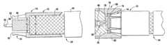
- FIG. 3shows a partial cross-sectional view of a mating connector interface that is disposed within a bore extending within a multiple-position connector assembly prior to the insertion of a snap-on electrical connector in the mating connector interface;
- FIG. 4shows an enlarged cross-sectional view of a snap-on electrical connector and a prepared end of a coaxial cable in mating engagement with a mating connector interface.
- FIGS. 1A , 1 B, and 1 Cillustrate an embodiment of a snap-on electrical connector 10 in accordance with the present invention.
- Snap-on connector 10includes a housing 12 and a plurality of fingers 14 extending an axial length L 3 from a first end 34 of the housing to a leading end 18 of the connector, each of the plurality of fingers extending axially around a circumference surrounding the longitudinal axis ‘AA’ of the connector.
- the plurality of fingers 14comprise a plurality of cantilevered beams separated by a plurality of slots.
- each of the plurality of fingers 14has a radially outwardly extending protrusion 16 disposed at or near the leading end 18 .
- housing 12includes an inner surface 20 having a first inner diameter region 22 , having first end 26 , second end 28 , and an inner diameter D 1 .
- Housing 12further includes a second inner diameter region 24 , having first end 30 , second end 32 , and an inner diameter D 2 .
- Second inner diameter region 24is disposed directly adjacent to first inner diameter region 22 and extends to the first end 34 of housing 12 .
- First and second inner diameter regionshave a combined axial length of L 2 .
- Inner diameter D 2is less than inner diameter D 1 such that the first end 26 of the first inner diameter region 22 and the second end 32 of second inner diameter region 24 define a shoulder 38 facing the second end 36 of housing 12 .
- inner surface 20 of housing 12further includes a tapered portion 40 disposed directly adjacent to the second end 28 of the first inner diameter region 22 and increasing in diameter toward the second end of the housing 36 for an axial length L 1 .
- Housing 12is preferably made of a conductive metal or a conductive metal alloy. Housing 12 can also be plated with one or more metals or metal alloys. In a preferred embodiment, housing 12 is made from beryllium copper (BeCu) covered by nickel plating then covered by gold plating. In a preferred embodiment, the nickel plating has a minimum thickness of 1.27 ⁇ m or 50 microinches and the gold plating has a thickness of 1.27 to 2.54 ⁇ m or 50 to 100 microinches. In a preferred embodiment the plurality of fingers 14 include the same material as housing 12 .
- BeCuberyllium copper
- the nickel platinghas a minimum thickness of 1.27 ⁇ m or 50 microinches and the gold plating has a thickness of 1.27 to 2.54 ⁇ m or 50 to 100 microinches.
- the plurality of fingers 14include the same material as housing 12 .
- the connector shown in FIGS. 1A-1Cis configured to allow at least a portion of a prepared end of a coaxial cable to be inserted into the second end 36 of housing 12 and through the first and second inner diameter regions.
- the coaxial cableincludes a central conductor that is circumferentially surrounded by a dielectric layer, which is circumferentially surrounded by an outer conductive layer, which is circumferentially surrounded by a jacket.
- the end of the coaxial cablecan be prepared by first removing a portion of a cable jacket to expose the outer conductive layer. Then a portion of the exposed outer conductive layer can be removed to expose the dielectric layer. Then a portion of the exposed dielectric layer can be removed to expose the center conductor.
- the prepared end of the coaxial cableincludes a center conductor exposed from a first point to a second point, a dielectric layer surrounding the center conductor exposed from the second point to a third point, and an outer conductive layer surrounding the dielectric layer exposed from a third point to a fourth point.
- FIG. 2illustrates a cross-sectional view of a prepared end of a coaxial cable 54 that is fully seated in connector 10 .
- the diameter D 1is greater than the outer diameter of an outer conductive layer 42 of the coaxial cable and the diameter D 2 is less than the outer diameter of the outer conductive layer 42 of the coaxial cable.
- the diameter D 1is less than the outer diameter of a jacket 44 of the coaxial cable and the diameter D 2 is greater than the outer diameter of a dielectric layer 46 of the coaxial cable.
- the prepared end of the coaxial cableis fully seated in connector 10 when, as shown in FIG.
- a leading end of the outer conductive layer 42abuts shoulder 38 and a leading end 50 of a center conductor 48 of the coaxial cable 54 extends beyond the leading end 18 of connector 10 .
- substantially the entire exposed portion of center conductor 48extends beyond the leading end 18 of connector 10 when the prepared end of the coaxial cable 54 is fully seated in the connector 10 , such as the entire exposed portion of center conductor 48 extending beyond a leading end 18 of connector 10 when the prepared end of the coaxial cable 54 is fully seated in the connector 10 .
- connector 10is sized to accept a coaxial cable 54 of the 50-ohm, 0.047-inch flexible type.
- a coaxial cable 54 of the 50-ohm, 0.047-inch flexible typeFor other size connectors, an 0.086 inch flex cable may be used.
- D 1is less than 0.090 inches, such as less than 0.060 inches, and even further such as less than 0.045 inches.
- connector 10can be used with other sizes and types of coaxial cables, in which case connector 10 can be sized accordingly.
- the plurality of fingers 14collectively provide an inner diameter of about D 2 when in the unbiased state.
- the plurality of fingers 14are capable of being flexed radially inward when subjected to an external inward-biasing force and have sufficient resiliency to return to their unbiased state when the external inward-biasing force is removed.
- the inner diameter of the plurality of fingers 14 in the unbiased stateis greater than the outer diameter of dielectric layer 46 to the extent that a gap 52 is provided between the inner diameter of the plurality of fingers 14 and the outer diameter of dielectric layer 46 when prepared end of the coaxial cable 54 is fully seated in connector 10 (as shown in FIG. 2 ).
- the difference between the inner diameter of the plurality of fingers 14 and the outer diameter of dielectric layer 46is from 0.01 inch to 0.001 inch, such as from 0.005 inch to 0.002 inch, such that when the prepared end of the coaxial cable 54 is fully seated and centered in connector 10 the radial width of gap 52 is from 0.005 inch to 0.0005 inch, such as from 0.0025 inch to 0.001 inch.
- At least a portion of the outer surface of outer conductive layer 42is soldered with at least a portion of the inner surface 20 of housing 12 .
- inner surface 20 of housing 12can be soldered to the outer surface of conductive layer 42 using Sn63 solder (not shown).
- FIG. 3shows a partial cross-sectional view of a mating connector interface 56 that is disposed within a bore extending within a multiple-position connector assembly 58 prior to the insertion of connector 10 in the mating connector interface 56 .
- Connector 10houses the prepared end of a coaxial cable 54 wherein an exposed portion of center conductor 48 extends beyond the leading end 18 of connector 10 .
- Mating connector interface 56includes a housing 60 including an inner surface 62 defining a longitudinal bore 72 along a longitudinal axis of the housing 60 , the housing having a proximal end 64 and a distal end 66 .
- a central terminal 68is disposed within the longitudinal bore 72 of housing 60 .
- Central terminal 68is adapted to receive center conductor 48 of coaxial cable 54 .
- a support member 70is disposed on inner surface 62 of housing 60 and holds the central terminal 68 within the longitudinal bore 72 .
- Inner surface 62includes a tapered portion 74 having a diameter D 3 at the distal end 66 of housing 60 and decreasing in diameter for an axial length L 4 to a diameter D 4 .
- Inner surface 62further includes a detent 76 (i.e., a groove circumferentially cut into inner surface 62 ) disposed between tapered portion 74 and proximal end 64 of housing 60 .
- Detent 76defines an inner diameter D 5 .
- Inner diameter D 5is preferably greater than D 4 and less than D 3 .
- D 3is less than 0.05 inches
- D 4is less than 0.04 inches
- D 5is less than 0.045 inches.
- central terminal 68includes a female socket contact that includes a plurality of tines 78 .
- Tines 78are preferably cantilevered and adapted to engage center conductor 48 of coaxial cable 54 .
- Central terminal 68is preferably constructed of a metal or metal alloy such as brass, copper, Kovar®, or stainless steel.
- Housing 60is made from an electrically conductive material, preferably a metal or metal alloy. In preferred embodiments, housing 60 is made from brass, copper, Kovar®, or stainless steel.
- Support member 70is preferably made from a dielectric material, such as polytetrafluoroethylene (PTFE) or glass, such as Corning 7070 glass.
- PTFEpolytetrafluoroethylene
- Corning 7070 glassa dielectric material, such as polytetrafluoroethylene (PTFE) or glass, such as Corning 7070 glass.
- mating connector interface 56is disposed within a bore extending within a multiple-position connector assembly 58 .
- the multiple-position connector assembly 58includes an assembly housing 80 and a fastening mechanism 82 to allow the connector assembly to be securely fastened to another object.
- the assembly housing 80is preferably a metal or metal alloy, such as aluminum alloy 6061-T6, which is a preferred material for aerospace applications, where weight reduction is important.
- the dimensions of assembly housing 80are not limited and can be expected to vary depending on the number of interfaces in the housing. In preferred embodiments, assembly housing 80 has a width W of from 0.15 to 0.30 inches, such as from 0.20 to 0.25 inches.
- assembly housing 80has a height H of from 0.30 to 0.60 inches, such as from 0.40 to 0.50 inches. In preferred embodiments, assembly housing 80 has a length (not shown) of from 0.8 inches to 1.5 inches, such as from 1 inch to 1.25 inches. Assembly housing 80 preferably includes a plurality of bores (not shown) for housing a plurality of connector interfaces. In a preferred embodiment, assembly housing 80 includes between 4 and 16 bores for housing an equivalent number of connector interfaces. In a particularly preferred embodiment, assembly housing 80 includes eight closely spaced bores for housing eight connector interfaces.
- a blind mate interconnect or bullet 84can be inserted into a shroud 86 on the opposite side of assembly housing 80 as connector interface 56 .
- Shroud 86houses male pin 88 that can be engaged by female socket contact (not shown) of bullet 84 thereby establishing electrical and mechanical communication between bullet 84 and male pin 88 .
- Connector 10is mated with mating connector interface 56 by inserting the leading end 18 of the connector 10 into distal end 66 of inner surface 62 , through tapered portion 74 , and by allowing an outer surface of protrusion 16 to engage detent 76 .
- Tapered portion 74preferably decreases to an inner diameter that is less than the maximum outer diameter (in the unbiased state) of the plurality of protrusions 16 such that when protrusions 16 are passed through tapered portion 74 , the plurality of fingers 14 are flexed radially inward and, due to their resilient nature, impart a biasing force against the inner surface of tapered portion 74 .
- Such biasing forcecauses connector 10 to snap into place when the outer surfaces of protrusions 16 engage the inner surface of detent 76 .
- center conductor 48 of coaxial cable 54is received in central terminal 68 , which, in a preferred embodiment, includes a female socket contact that includes a plurality of tines 78 .
- the tines 78are cantilevered and grip center conductor 48 when connector 10 and mating connector interface 56 are in full mating engagement.
- FIG. 4shows an enlarged cross-sectional view of connector 10 and prepared end of a coaxial cable 54 in full mating engagement with mating connector interface 56 .
- Mating connector interface 56includes housing 60 that houses central terminal 68 and support member 70 .
- the outer surface of protrusion 16engages the inner surface of detent 76 .
- tines 78engage the center conductor 48 of the coaxial cable 54 .
- each of the plurality of fingers 14are flexed radially inward when connector 10 is in full mating engagement with mating connector interface 56 .
- detent 76 and the plurality of fingers 14may be mutually adapted to allow the inner surfaces of the plurality of fingers 14 to lie parallel to an outer surface of the dielectric layer of the coaxial cable when connector 10 and mating connector interface 56 are fully mated together.
- protrusion 16When connector 10 is in fully mating engagement with mating connector interface 56 , at least the outer surface of protrusion 16 is electrically coupled to housing 60 and center conductor 48 of coaxial cable 54 is electrically coupled to central terminal 68 .
Landscapes
- Coupling Device And Connection With Printed Circuit (AREA)
Abstract
Description
Claims (19)
Priority Applications (3)
| Application Number | Priority Date | Filing Date | Title |
|---|---|---|---|
| US12/152,692US7500873B1 (en) | 2008-05-16 | 2008-05-16 | Snap-on coaxial cable connector |
| PCT/US2009/002884WO2009139836A1 (en) | 2008-05-16 | 2009-05-08 | Snap-on coaxial cable connector |
| EP09746925.8AEP2304847B1 (en) | 2008-05-16 | 2009-05-08 | Snap-on coaxial cable connector |
Applications Claiming Priority (1)
| Application Number | Priority Date | Filing Date | Title |
|---|---|---|---|
| US12/152,692US7500873B1 (en) | 2008-05-16 | 2008-05-16 | Snap-on coaxial cable connector |
Publications (1)
| Publication Number | Publication Date |
|---|---|
| US7500873B1true US7500873B1 (en) | 2009-03-10 |
Family
ID=40417003
Family Applications (1)
| Application Number | Title | Priority Date | Filing Date |
|---|---|---|---|
| US12/152,692ActiveUS7500873B1 (en) | 2008-05-16 | 2008-05-16 | Snap-on coaxial cable connector |
Country Status (3)
| Country | Link |
|---|---|
| US (1) | US7500873B1 (en) |
| EP (1) | EP2304847B1 (en) |
| WO (1) | WO2009139836A1 (en) |
Cited By (39)
| Publication number | Priority date | Publication date | Assignee | Title |
|---|---|---|---|---|
| US20100015850A1 (en)* | 2008-07-15 | 2010-01-21 | Casey Roy Stein | Low-profile mounted push-on connector |
| US20100062638A1 (en)* | 2007-10-08 | 2010-03-11 | Winchester Electronics Corporation | Modular interconnect apparatus |
| US7704077B1 (en)* | 2009-04-13 | 2010-04-27 | Tyco Electronics Corporation | Low loss board to board connection system |
| US20120178281A1 (en)* | 2011-01-11 | 2012-07-12 | Asustek Computer Inc. | Connector Module and Electronic Device Using the Same |
| US20130337682A1 (en)* | 2012-06-13 | 2013-12-19 | Eric James Paulus | Variable impedance coaxial connector interface device |
| US8803008B2 (en) | 2011-03-03 | 2014-08-12 | Sigma Electric Manufacturing Corporation | Conduit connector and methods for making and using the same |
| US8857039B2 (en) | 2010-02-19 | 2014-10-14 | Sigma Electric Manufacturing Corporation | Electrical box conduit connectors and methods for making and using the same |
| US8888526B2 (en) | 2010-08-10 | 2014-11-18 | Corning Gilbert, Inc. | Coaxial cable connector with radio frequency interference and grounding shield |
| US9048599B2 (en) | 2013-10-28 | 2015-06-02 | Corning Gilbert Inc. | Coaxial cable connector having a gripping member with a notch and disposed inside a shell |
| US9071019B2 (en) | 2010-10-27 | 2015-06-30 | Corning Gilbert, Inc. | Push-on cable connector with a coupler and retention and release mechanism |
| WO2015112562A1 (en)* | 2014-01-21 | 2015-07-30 | Ppc Broadband, Inc. | Cable connector structured for reassembly and method thereof |
| US9136654B2 (en) | 2012-01-05 | 2015-09-15 | Corning Gilbert, Inc. | Quick mount connector for a coaxial cable |
| US9147963B2 (en) | 2012-11-29 | 2015-09-29 | Corning Gilbert Inc. | Hardline coaxial connector with a locking ferrule |
| US9153911B2 (en) | 2013-02-19 | 2015-10-06 | Corning Gilbert Inc. | Coaxial cable continuity connector |
| US9166348B2 (en) | 2010-04-13 | 2015-10-20 | Corning Gilbert Inc. | Coaxial connector with inhibited ingress and improved grounding |
| US9172154B2 (en) | 2013-03-15 | 2015-10-27 | Corning Gilbert Inc. | Coaxial cable connector with integral RFI protection |
| US9190744B2 (en) | 2011-09-14 | 2015-11-17 | Corning Optical Communications Rf Llc | Coaxial cable connector with radio frequency interference and grounding shield |
| US9231388B2 (en) | 2011-09-01 | 2016-01-05 | Sigma Electric Manufactruing Corporation | Conduit connector and method for making and using the same |
| US9287659B2 (en) | 2012-10-16 | 2016-03-15 | Corning Optical Communications Rf Llc | Coaxial cable connector with integral RFI protection |
| US20160197438A1 (en)* | 2013-08-09 | 2016-07-07 | Autonetworks Technologies, Ltd. | Connector |
| US9407016B2 (en) | 2012-02-22 | 2016-08-02 | Corning Optical Communications Rf Llc | Coaxial cable connector with integral continuity contacting portion |
| US9425548B2 (en) | 2012-11-09 | 2016-08-23 | Commscope Technologies Llc | Resilient coaxial connector interface and method of manufacture |
| US9525220B1 (en) | 2015-11-25 | 2016-12-20 | Corning Optical Communications LLC | Coaxial cable connector |
| US9548557B2 (en) | 2013-06-26 | 2017-01-17 | Corning Optical Communications LLC | Connector assemblies and methods of manufacture |
| US9548572B2 (en) | 2014-11-03 | 2017-01-17 | Corning Optical Communications LLC | Coaxial cable connector having a coupler and a post with a contacting portion and a shoulder |
| US9590287B2 (en) | 2015-02-20 | 2017-03-07 | Corning Optical Communications Rf Llc | Surge protected coaxial termination |
| US9762008B2 (en) | 2013-05-20 | 2017-09-12 | Corning Optical Communications Rf Llc | Coaxial cable connector with integral RFI protection |
| US9859631B2 (en) | 2011-09-15 | 2018-01-02 | Corning Optical Communications Rf Llc | Coaxial cable connector with integral radio frequency interference and grounding shield |
| US20180124921A1 (en)* | 2016-11-03 | 2018-05-03 | Tyco Electronics (Shanghai) Co. Ltd. | Adapter, Receptacle and Connector Assembly |
| US10033122B2 (en) | 2015-02-20 | 2018-07-24 | Corning Optical Communications Rf Llc | Cable or conduit connector with jacket retention feature |
| US10211547B2 (en) | 2015-09-03 | 2019-02-19 | Corning Optical Communications Rf Llc | Coaxial cable connector |
| US20190131735A1 (en)* | 2017-10-27 | 2019-05-02 | Commscope Technologies Llc | Coaxial male connector, coaxial female connector and assembly thereof |
| US10290958B2 (en) | 2013-04-29 | 2019-05-14 | Corning Optical Communications Rf Llc | Coaxial cable connector with integral RFI protection and biasing ring |
| US10756455B2 (en) | 2005-01-25 | 2020-08-25 | Corning Optical Communications Rf Llc | Electrical connector with grounding member |
| US20210281024A1 (en)* | 2018-11-28 | 2021-09-09 | Corning Optical Communications Rf Llc | Locking rf coaxial connector |
| US11437766B2 (en) | 2010-11-22 | 2022-09-06 | Commscope Technologies Llc | Connector and coaxial cable with molecular bond interconnection |
| US11462843B2 (en) | 2010-11-22 | 2022-10-04 | Commscope Technologies Llc | Ultrasonic weld interconnection coaxial connector and interconnection with coaxial cable |
| US20220337008A1 (en)* | 2021-04-19 | 2022-10-20 | Hyun Duk KIM | Cable adaptor |
| US12034264B2 (en) | 2021-03-31 | 2024-07-09 | Corning Optical Communications Rf Llc | Coaxial cable connector assemblies with outer conductor engagement features and methods for using the same |
Citations (16)
| Publication number | Priority date | Publication date | Assignee | Title |
|---|---|---|---|---|
| US4717355A (en)* | 1986-10-24 | 1988-01-05 | Raychem Corp. | Coaxial connector moisture seal |
| US4772222A (en)* | 1987-10-15 | 1988-09-20 | Amp Incorporated | Coaxial LMC connector |
| US5393244A (en)* | 1994-01-25 | 1995-02-28 | John Mezzalingua Assoc. Inc. | Twist-on coaxial cable end connector with internal post |
| US5488268A (en)* | 1991-04-04 | 1996-01-30 | Magnetek, Inc. | Electrical connector with improved centering of mating terminal pins, for a fluorescent-lighting ballast |
| US5906511A (en)* | 1994-10-17 | 1999-05-25 | The Whitaker Corporation | Multi-position coaxial cable connector |
| US6705875B2 (en)* | 2001-03-29 | 2004-03-16 | Harting Kgaa | Coaxial plug member |
| US6780042B1 (en)* | 2000-08-03 | 2004-08-24 | Rutgers, The State University Of New Jersey | Active quick connecting/disconnecting connector |
| US6827608B2 (en) | 2002-08-22 | 2004-12-07 | Corning Gilbert Inc. | High frequency, blind mate, coaxial interconnect |
| US6935866B2 (en)* | 2002-04-02 | 2005-08-30 | Adc Telecommunications, Inc. | Card edge coaxial connector |
| US7077697B2 (en) | 2004-09-09 | 2006-07-18 | Corning Gilbert Inc. | Snap-in float-mount electrical connector |
| US7128604B2 (en) | 2004-06-14 | 2006-10-31 | Corning Gilbert Inc. | High power coaxial interconnect |
| US20060246774A1 (en)* | 2005-04-29 | 2006-11-02 | Buck Bruce D | Coaxial cable connector assembly, system, and method |
| US20070004276A1 (en) | 2005-07-01 | 2007-01-04 | Stein Casey R | Low extraction force connector interface |
| US7165974B2 (en) | 2004-10-14 | 2007-01-23 | Corning Gilbert Inc. | Multiple-position push-on electrical connector |
| US7192308B2 (en)* | 2000-05-10 | 2007-03-20 | Thomas & Betts International, Inc. | Coaxial connector having detachable locking sleeve |
| US7288002B2 (en)* | 2005-10-19 | 2007-10-30 | Thomas & Betts International, Inc. | Coaxial cable connector with self-gripping and self-sealing features |
Family Cites Families (3)
| Publication number | Priority date | Publication date | Assignee | Title |
|---|---|---|---|---|
| US3810073A (en)* | 1973-01-26 | 1974-05-07 | Omni Spectra Inc | Connector locking mechanism |
| US5195906A (en)* | 1991-12-27 | 1993-03-23 | Production Products Company | Coaxial cable end connector |
| TW501806U (en)* | 2001-07-27 | 2002-09-01 | Hon Hai Prec Ind Co Ltd | Wire-cable connector assembly |
- 2008
- 2008-05-16USUS12/152,692patent/US7500873B1/enactiveActive
- 2009
- 2009-05-08EPEP09746925.8Apatent/EP2304847B1/ennot_activeNot-in-force
- 2009-05-08WOPCT/US2009/002884patent/WO2009139836A1/enactiveApplication Filing
Patent Citations (18)
| Publication number | Priority date | Publication date | Assignee | Title |
|---|---|---|---|---|
| US4717355A (en)* | 1986-10-24 | 1988-01-05 | Raychem Corp. | Coaxial connector moisture seal |
| US4772222A (en)* | 1987-10-15 | 1988-09-20 | Amp Incorporated | Coaxial LMC connector |
| US5488268A (en)* | 1991-04-04 | 1996-01-30 | Magnetek, Inc. | Electrical connector with improved centering of mating terminal pins, for a fluorescent-lighting ballast |
| US5393244A (en)* | 1994-01-25 | 1995-02-28 | John Mezzalingua Assoc. Inc. | Twist-on coaxial cable end connector with internal post |
| US5906511A (en)* | 1994-10-17 | 1999-05-25 | The Whitaker Corporation | Multi-position coaxial cable connector |
| US7192308B2 (en)* | 2000-05-10 | 2007-03-20 | Thomas & Betts International, Inc. | Coaxial connector having detachable locking sleeve |
| US6780042B1 (en)* | 2000-08-03 | 2004-08-24 | Rutgers, The State University Of New Jersey | Active quick connecting/disconnecting connector |
| US6705875B2 (en)* | 2001-03-29 | 2004-03-16 | Harting Kgaa | Coaxial plug member |
| US6935866B2 (en)* | 2002-04-02 | 2005-08-30 | Adc Telecommunications, Inc. | Card edge coaxial connector |
| US7118382B2 (en)* | 2002-04-02 | 2006-10-10 | Adc Telecommunications, Inc. | Card edge coaxial connector |
| US7357641B2 (en)* | 2002-04-02 | 2008-04-15 | Adc Telecommunications, Inc. | Card edge coaxial connector |
| US6827608B2 (en) | 2002-08-22 | 2004-12-07 | Corning Gilbert Inc. | High frequency, blind mate, coaxial interconnect |
| US7128604B2 (en) | 2004-06-14 | 2006-10-31 | Corning Gilbert Inc. | High power coaxial interconnect |
| US7077697B2 (en) | 2004-09-09 | 2006-07-18 | Corning Gilbert Inc. | Snap-in float-mount electrical connector |
| US7165974B2 (en) | 2004-10-14 | 2007-01-23 | Corning Gilbert Inc. | Multiple-position push-on electrical connector |
| US20060246774A1 (en)* | 2005-04-29 | 2006-11-02 | Buck Bruce D | Coaxial cable connector assembly, system, and method |
| US20070004276A1 (en) | 2005-07-01 | 2007-01-04 | Stein Casey R | Low extraction force connector interface |
| US7288002B2 (en)* | 2005-10-19 | 2007-10-30 | Thomas & Betts International, Inc. | Coaxial cable connector with self-gripping and self-sealing features |
Cited By (70)
| Publication number | Priority date | Publication date | Assignee | Title |
|---|---|---|---|---|
| US10756455B2 (en) | 2005-01-25 | 2020-08-25 | Corning Optical Communications Rf Llc | Electrical connector with grounding member |
| US20100062638A1 (en)* | 2007-10-08 | 2010-03-11 | Winchester Electronics Corporation | Modular interconnect apparatus |
| US7896656B2 (en)* | 2007-10-08 | 2011-03-01 | Winchester Electronics Corporation | Modular interconnect apparatus |
| US20110217871A1 (en)* | 2007-10-08 | 2011-09-08 | Winchester Electronics Corporation | Modular interconnect apparatus |
| US8157572B2 (en)* | 2007-10-08 | 2012-04-17 | Winchester Electronics Corporation | Modular interconnect apparatus |
| US20100015850A1 (en)* | 2008-07-15 | 2010-01-21 | Casey Roy Stein | Low-profile mounted push-on connector |
| US7704077B1 (en)* | 2009-04-13 | 2010-04-27 | Tyco Electronics Corporation | Low loss board to board connection system |
| US8857039B2 (en) | 2010-02-19 | 2014-10-14 | Sigma Electric Manufacturing Corporation | Electrical box conduit connectors and methods for making and using the same |
| US9166348B2 (en) | 2010-04-13 | 2015-10-20 | Corning Gilbert Inc. | Coaxial connector with inhibited ingress and improved grounding |
| US10312629B2 (en) | 2010-04-13 | 2019-06-04 | Corning Optical Communications Rf Llc | Coaxial connector with inhibited ingress and improved grounding |
| US9905959B2 (en) | 2010-04-13 | 2018-02-27 | Corning Optical Communication RF LLC | Coaxial connector with inhibited ingress and improved grounding |
| US8888526B2 (en) | 2010-08-10 | 2014-11-18 | Corning Gilbert, Inc. | Coaxial cable connector with radio frequency interference and grounding shield |
| US9071019B2 (en) | 2010-10-27 | 2015-06-30 | Corning Gilbert, Inc. | Push-on cable connector with a coupler and retention and release mechanism |
| US11437767B2 (en) | 2010-11-22 | 2022-09-06 | Commscope Technologies Llc | Connector and coaxial cable with molecular bond interconnection |
| US11735874B2 (en) | 2010-11-22 | 2023-08-22 | Commscope Technologies Llc | Connector and coaxial cable with molecular bond interconnection |
| US12113317B2 (en) | 2010-11-22 | 2024-10-08 | Outdoor Wireless Networks LLC | Connector and coaxial cable with molecular bond interconnection |
| US12100925B2 (en) | 2010-11-22 | 2024-09-24 | Outdoor Wireless Networks LLC | Ultrasonic weld interconnection coaxial connector and interconnection with coaxial cable |
| US11437766B2 (en) | 2010-11-22 | 2022-09-06 | Commscope Technologies Llc | Connector and coaxial cable with molecular bond interconnection |
| US11462843B2 (en) | 2010-11-22 | 2022-10-04 | Commscope Technologies Llc | Ultrasonic weld interconnection coaxial connector and interconnection with coaxial cable |
| US11757212B2 (en) | 2010-11-22 | 2023-09-12 | Commscope Technologies Llc | Ultrasonic weld interconnection coaxial connector and interconnection with coaxial cable |
| US20120178281A1 (en)* | 2011-01-11 | 2012-07-12 | Asustek Computer Inc. | Connector Module and Electronic Device Using the Same |
| US8506318B2 (en)* | 2011-01-11 | 2013-08-13 | Asustek Computer Inc. | Connector module and electronic device using the same |
| US8803008B2 (en) | 2011-03-03 | 2014-08-12 | Sigma Electric Manufacturing Corporation | Conduit connector and methods for making and using the same |
| USRE47893E1 (en) | 2011-03-03 | 2020-03-03 | Sigma Electric Manufacturing Corporation | Conduit connector and methods for making and using the same |
| US9231388B2 (en) | 2011-09-01 | 2016-01-05 | Sigma Electric Manufactruing Corporation | Conduit connector and method for making and using the same |
| US9190744B2 (en) | 2011-09-14 | 2015-11-17 | Corning Optical Communications Rf Llc | Coaxial cable connector with radio frequency interference and grounding shield |
| US9859631B2 (en) | 2011-09-15 | 2018-01-02 | Corning Optical Communications Rf Llc | Coaxial cable connector with integral radio frequency interference and grounding shield |
| US9484645B2 (en) | 2012-01-05 | 2016-11-01 | Corning Optical Communications Rf Llc | Quick mount connector for a coaxial cable |
| US9136654B2 (en) | 2012-01-05 | 2015-09-15 | Corning Gilbert, Inc. | Quick mount connector for a coaxial cable |
| US9768565B2 (en) | 2012-01-05 | 2017-09-19 | Corning Optical Communications Rf Llc | Quick mount connector for a coaxial cable |
| US9407016B2 (en) | 2012-02-22 | 2016-08-02 | Corning Optical Communications Rf Llc | Coaxial cable connector with integral continuity contacting portion |
| US20150050834A1 (en)* | 2012-06-13 | 2015-02-19 | Corning Optical Communications Rf Llc | Variable Impedance Coaxial Connector Interface Device |
| US8979581B2 (en)* | 2012-06-13 | 2015-03-17 | Corning Gilbert Inc. | Variable impedance coaxial connector interface device |
| US9312612B2 (en)* | 2012-06-13 | 2016-04-12 | Corning Optical Communications Rf Llc | Variable impedance coaxial connector interface device |
| US20130337682A1 (en)* | 2012-06-13 | 2013-12-19 | Eric James Paulus | Variable impedance coaxial connector interface device |
| US10236636B2 (en) | 2012-10-16 | 2019-03-19 | Corning Optical Communications Rf Llc | Coaxial cable connector with integral RFI protection |
| US9722363B2 (en) | 2012-10-16 | 2017-08-01 | Corning Optical Communications Rf Llc | Coaxial cable connector with integral RFI protection |
| US9912105B2 (en) | 2012-10-16 | 2018-03-06 | Corning Optical Communications Rf Llc | Coaxial cable connector with integral RFI protection |
| US9287659B2 (en) | 2012-10-16 | 2016-03-15 | Corning Optical Communications Rf Llc | Coaxial cable connector with integral RFI protection |
| US9425548B2 (en) | 2012-11-09 | 2016-08-23 | Commscope Technologies Llc | Resilient coaxial connector interface and method of manufacture |
| US9147963B2 (en) | 2012-11-29 | 2015-09-29 | Corning Gilbert Inc. | Hardline coaxial connector with a locking ferrule |
| US9153911B2 (en) | 2013-02-19 | 2015-10-06 | Corning Gilbert Inc. | Coaxial cable continuity connector |
| US9172154B2 (en) | 2013-03-15 | 2015-10-27 | Corning Gilbert Inc. | Coaxial cable connector with integral RFI protection |
| US10290958B2 (en) | 2013-04-29 | 2019-05-14 | Corning Optical Communications Rf Llc | Coaxial cable connector with integral RFI protection and biasing ring |
| US9762008B2 (en) | 2013-05-20 | 2017-09-12 | Corning Optical Communications Rf Llc | Coaxial cable connector with integral RFI protection |
| US10396508B2 (en) | 2013-05-20 | 2019-08-27 | Corning Optical Communications Rf Llc | Coaxial cable connector with integral RFI protection |
| US9548557B2 (en) | 2013-06-26 | 2017-01-17 | Corning Optical Communications LLC | Connector assemblies and methods of manufacture |
| US20160197438A1 (en)* | 2013-08-09 | 2016-07-07 | Autonetworks Technologies, Ltd. | Connector |
| US9666983B2 (en)* | 2013-08-09 | 2017-05-30 | Autonetworks Technologies, Ltd. | Connector |
| US9048599B2 (en) | 2013-10-28 | 2015-06-02 | Corning Gilbert Inc. | Coaxial cable connector having a gripping member with a notch and disposed inside a shell |
| WO2015112562A1 (en)* | 2014-01-21 | 2015-07-30 | Ppc Broadband, Inc. | Cable connector structured for reassembly and method thereof |
| US9484646B2 (en) | 2014-01-21 | 2016-11-01 | Ppc Broadband, Inc. | Cable connector structured for reassembly and method thereof |
| US9548572B2 (en) | 2014-11-03 | 2017-01-17 | Corning Optical Communications LLC | Coaxial cable connector having a coupler and a post with a contacting portion and a shoulder |
| US9991651B2 (en) | 2014-11-03 | 2018-06-05 | Corning Optical Communications Rf Llc | Coaxial cable connector with post including radially expanding tabs |
| US9590287B2 (en) | 2015-02-20 | 2017-03-07 | Corning Optical Communications Rf Llc | Surge protected coaxial termination |
| US10033122B2 (en) | 2015-02-20 | 2018-07-24 | Corning Optical Communications Rf Llc | Cable or conduit connector with jacket retention feature |
| US10211547B2 (en) | 2015-09-03 | 2019-02-19 | Corning Optical Communications Rf Llc | Coaxial cable connector |
| US9882320B2 (en) | 2015-11-25 | 2018-01-30 | Corning Optical Communications Rf Llc | Coaxial cable connector |
| US9525220B1 (en) | 2015-11-25 | 2016-12-20 | Corning Optical Communications LLC | Coaxial cable connector |
| US10973124B2 (en)* | 2016-11-03 | 2021-04-06 | Tyco Electronics (Shanghai) Co. Ltd. | Connector assembly having an adapter to connect two circuit boards |
| US20180124921A1 (en)* | 2016-11-03 | 2018-05-03 | Tyco Electronics (Shanghai) Co. Ltd. | Adapter, Receptacle and Connector Assembly |
| US10637172B2 (en)* | 2017-10-27 | 2020-04-28 | Commscope Technologies Llc | Coaxial male connector, coaxial female connector and assembly thereof |
| US20190131735A1 (en)* | 2017-10-27 | 2019-05-02 | Commscope Technologies Llc | Coaxial male connector, coaxial female connector and assembly thereof |
| US11728598B2 (en)* | 2018-11-28 | 2023-08-15 | Corning Optical Communications Rf Llc | Locking RF coaxial connector |
| US20210281024A1 (en)* | 2018-11-28 | 2021-09-09 | Corning Optical Communications Rf Llc | Locking rf coaxial connector |
| US20230327382A1 (en)* | 2018-11-28 | 2023-10-12 | Corning Optical Communications Rf Llc | Locking rf coaxial connector |
| US12142882B2 (en)* | 2018-11-28 | 2024-11-12 | Corning Optical Communications Rf Llc | Locking RF coaxial connector |
| US12034264B2 (en) | 2021-03-31 | 2024-07-09 | Corning Optical Communications Rf Llc | Coaxial cable connector assemblies with outer conductor engagement features and methods for using the same |
| US20220337008A1 (en)* | 2021-04-19 | 2022-10-20 | Hyun Duk KIM | Cable adaptor |
| US12068561B2 (en)* | 2021-04-19 | 2024-08-20 | Sensorview Co., Ltd. | Cable adaptor |
Also Published As
| Publication number | Publication date |
|---|---|
| EP2304847B1 (en) | 2016-01-13 |
| WO2009139836A1 (en) | 2009-11-19 |
| EP2304847A1 (en) | 2011-04-06 |
Similar Documents
| Publication | Publication Date | Title |
|---|---|---|
| US7500873B1 (en) | Snap-on coaxial cable connector | |
| EP3167512B1 (en) | Electrical connector for high-speed transmission using twisted-pair cable | |
| EP3555968B1 (en) | Multiple piece contact for an electrical connector | |
| US6386913B1 (en) | Electrical connector for micro co-axial conductors | |
| EP1547203B1 (en) | High frequency, blind mate, coaxial interconnect | |
| US7563133B2 (en) | Low extraction force connector interface | |
| US4619496A (en) | Coaxial plug and jack connectors | |
| EP0915536B1 (en) | Coaxial connector | |
| US20100304579A1 (en) | Low Resistance Connector For Printed Circuit Board | |
| EP2027630B1 (en) | Coaxial connector | |
| JPH0676890A (en) | Coaxial connector assembly | |
| JP2002252066A (en) | Right-angle type coaxial electric connector | |
| US20030224658A1 (en) | Electrical connector | |
| KR20240017825A (en) | Electrical connector assembly with RF impedance element | |
| US6371806B1 (en) | Cable end connector having accurately positioned connection terminal therein | |
| GB2139018A (en) | Coaxial plug and jack connectors | |
| AU2005251152B2 (en) | Hermaphroditic handle socket assembly and pin assembly | |
| GB2032710A (en) | Electrical connector assembly | |
| US5061207A (en) | Connector for a shielded coaxial cable | |
| US9948019B2 (en) | Cable assembly | |
| US6416357B1 (en) | Cable end connector with low profile after assembly | |
| EP3190666A1 (en) | Pin for adapting electrical connectors, and a kit of parts including same | |
| US20100330841A1 (en) | Cable connector for terminating different types of cables | |
| CN118661342A (en) | Single Pair Ethernet Connection System | |
| EP1640755B1 (en) | Optical connector assemblies |
Legal Events
| Date | Code | Title | Description |
|---|---|---|---|
| AS | Assignment | Owner name:CORNING GILBERT INC., ARIZONA Free format text:ASSIGNMENT OF ASSIGNORS INTEREST;ASSIGNOR:HART, DENNIS FRANCIS;REEL/FRAME:021005/0346 Effective date:20080508 | |
| STCF | Information on status: patent grant | Free format text:PATENTED CASE | |
| FPAY | Fee payment | Year of fee payment:4 | |
| AS | Assignment | Owner name:CORNING OPTICAL COMMUNICATIONS RF LLC, ARIZONA Free format text:CHANGE OF NAME;ASSIGNOR:CORNING GILBERT, INC.;REEL/FRAME:036687/0562 Effective date:20140122 | |
| FPAY | Fee payment | Year of fee payment:8 | |
| MAFP | Maintenance fee payment | Free format text:PAYMENT OF MAINTENANCE FEE, 12TH YEAR, LARGE ENTITY (ORIGINAL EVENT CODE: M1553); ENTITY STATUS OF PATENT OWNER: LARGE ENTITY Year of fee payment:12 | |
| AS | Assignment | Owner name:CORNING OPTICAL COMMUNICATIONS RF LLC, ARIZONA Free format text:CORRECTIVE ASSIGNMENT TO CORRECT THE PROPERTY LISTED IN THE ORIGINAL COVER SHEET PREVIOUSLY RECORDED AT REEL: 036687 FRAME: 0562. ASSIGNOR(S) HEREBY CONFIRMS THE ASSIGNMENT;ASSIGNOR:CORNING GILBERT, INC.;REEL/FRAME:058300/0843 Effective date:20140122 |