US7500261B1 - Multi-point multi-channel data distribution system - Google Patents
Multi-point multi-channel data distribution systemDownload PDFInfo
- Publication number
- US7500261B1 US7500261B1US10/020,030US2003001AUS7500261B1US 7500261 B1US7500261 B1US 7500261B1US 2003001 AUS2003001 AUS 2003001AUS 7500261 B1US7500261 B1US 7500261B1
- Authority
- US
- United States
- Prior art keywords
- signal
- multicast
- data
- subscriber
- unicast
- Prior art date
- Legal status (The legal status is an assumption and is not a legal conclusion. Google has not performed a legal analysis and makes no representation as to the accuracy of the status listed.)
- Expired - Lifetime, expires
Links
- 230000005540biological transmissionEffects0.000claimsabstractdescription45
- 238000000034methodMethods0.000claimsdescription22
- 238000004891communicationMethods0.000claimsdescription9
- 230000008569processEffects0.000claimsdescription8
- 238000012545processingMethods0.000claimsdescription6
- 238000012546transferMethods0.000abstractdescription8
- 230000002452interceptive effectEffects0.000abstractdescription7
- 230000000593degrading effectEffects0.000abstractdescription3
- 238000010586diagramMethods0.000description10
- 238000011144upstream manufacturingMethods0.000description7
- 230000007246mechanismEffects0.000description3
- 230000015556catabolic processEffects0.000description2
- 230000006835compressionEffects0.000description2
- 238000007906compressionMethods0.000description2
- 238000006731degradation reactionMethods0.000description2
- 230000009977dual effectEffects0.000description2
- 230000000694effectsEffects0.000description2
- 238000005516engineering processMethods0.000description2
- 230000000977initiatory effectEffects0.000description2
- 230000004044responseEffects0.000description2
- 238000006424Flood reactionMethods0.000description1
- 238000013459approachMethods0.000description1
- 238000013475authorizationMethods0.000description1
- 230000008901benefitEffects0.000description1
- 238000011161developmentMethods0.000description1
- 230000009365direct transmissionEffects0.000description1
- 230000003116impacting effectEffects0.000description1
- 238000007726management methodMethods0.000description1
- 238000012986modificationMethods0.000description1
- 230000004048modificationEffects0.000description1
- 230000006855networkingEffects0.000description1
- 238000011160researchMethods0.000description1
- 238000001228spectrumMethods0.000description1
- 230000001360synchronised effectEffects0.000description1
Images


Classifications
- H—ELECTRICITY
- H04—ELECTRIC COMMUNICATION TECHNIQUE
- H04N—PICTORIAL COMMUNICATION, e.g. TELEVISION
- H04N7/00—Television systems
- H04N7/20—Adaptations for transmission via a GHz frequency band, e.g. via satellite
- H—ELECTRICITY
- H04—ELECTRIC COMMUNICATION TECHNIQUE
- H04H—BROADCAST COMMUNICATION
- H04H20/00—Arrangements for broadcast or for distribution combined with broadcast
- H04H20/28—Arrangements for simultaneous broadcast of plural pieces of information
- H04H20/33—Arrangements for simultaneous broadcast of plural pieces of information by plural channels
- H—ELECTRICITY
- H04—ELECTRIC COMMUNICATION TECHNIQUE
- H04H—BROADCAST COMMUNICATION
- H04H20/00—Arrangements for broadcast or for distribution combined with broadcast
- H04H20/65—Arrangements characterised by transmission systems for broadcast
- H04H20/71—Wireless systems
- H04H20/72—Wireless systems of terrestrial networks
- H—ELECTRICITY
- H04—ELECTRIC COMMUNICATION TECHNIQUE
- H04N—PICTORIAL COMMUNICATION, e.g. TELEVISION
- H04N21/00—Selective content distribution, e.g. interactive television or video on demand [VOD]
- H04N21/40—Client devices specifically adapted for the reception of or interaction with content, e.g. set-top-box [STB]; Operations thereof
- H04N21/43—Processing of content or additional data, e.g. demultiplexing additional data from a digital video stream; Elementary client operations, e.g. monitoring of home network or synchronising decoder's clock; Client middleware
- H04N21/436—Interfacing a local distribution network, e.g. communicating with another STB or one or more peripheral devices inside the home
- H04N21/43615—Interfacing a Home Network, e.g. for connecting the client to a plurality of peripherals
- H—ELECTRICITY
- H04—ELECTRIC COMMUNICATION TECHNIQUE
- H04N—PICTORIAL COMMUNICATION, e.g. TELEVISION
- H04N21/00—Selective content distribution, e.g. interactive television or video on demand [VOD]
- H04N21/40—Client devices specifically adapted for the reception of or interaction with content, e.g. set-top-box [STB]; Operations thereof
- H04N21/43—Processing of content or additional data, e.g. demultiplexing additional data from a digital video stream; Elementary client operations, e.g. monitoring of home network or synchronising decoder's clock; Client middleware
- H04N21/438—Interfacing the downstream path of the transmission network originating from a server, e.g. retrieving encoded video stream packets from an IP network
- H04N21/4382—Demodulation or channel decoding, e.g. QPSK demodulation
- H—ELECTRICITY
- H04—ELECTRIC COMMUNICATION TECHNIQUE
- H04N—PICTORIAL COMMUNICATION, e.g. TELEVISION
- H04N21/00—Selective content distribution, e.g. interactive television or video on demand [VOD]
- H04N21/60—Network structure or processes for video distribution between server and client or between remote clients; Control signalling between clients, server and network components; Transmission of management data between server and client, e.g. sending from server to client commands for recording incoming content stream; Communication details between server and client
- H04N21/63—Control signaling related to video distribution between client, server and network components; Network processes for video distribution between server and clients or between remote clients, e.g. transmitting basic layer and enhancement layers over different transmission paths, setting up a peer-to-peer communication via Internet between remote STB's; Communication protocols; Addressing
- H04N21/643—Communication protocols
- H04N21/64322—IP
Definitions
- the present inventionrelates generally to telecommunications systems, and more particularly to a system for providing direct transmission of multiple encoded video, audio, and other data streams to a plurality of subscribers over a shared media.
- shared media multipoint data distribution systemssuch as cable and broadband wireless are bandwidth limited on a per channel basis. Therefore, bandwidth is wasted anytime more than one user requests the same video/audio/data stream. This in turn reduces the overall bandwidth available to other users sharing the same channel for their individual interests.
- the present inventionovercomes the aforementioned problems of the prior art and achieves an advance in the field by providing a system for the efficient distribution of live and stored audio/video streams to multiple subscribers without degrading normal data delivery services.
- the present systemsegments one or more frequency bands into sub-bands, or channels, each of which is capable of carrying encoded audio, video, and other data streams, to a plurality of subscribers.
- Each channel transmitted in the present systemprovides full-duplex operation so that each subscriber may indicate what specific services are desired, such as audio/video broadcast, two-way data transfer, video library access, pay-per-view video, interactive video, and audio file transfer.
- a transmission headend facilitybroadcasts multiple channels of video/audio data (e.g., Internet data) in unicast mode via a shared media transmission facility (wireless, cable, etc.) to multiple subscribers. Simultaneously, selected video/audio/data (e.g., pay-per view) is transmitted in IP (Internet Protocol) multicast mode over one or more channels of the segmented frequency band.
- IPInternet Protocol
- the subscriberis provided a device (a ‘subscriber unit’) which simultaneously and dynamically demodulates 2 or more channels (on different frequencies) and interleaves the information over a single ethernet interface connected to one or more IP enabled devices.
- Each subscriberthus has the capability of, for example, receiving a video stream concurrent with many other subscribers while simultaneously interacting uniquely with the Internet or other data network.
- a number of subscribersmay thus simultaneously share the same interactive channel without performance degradation, up to the limit of the subscriber network.
- an IP enabled television set or subscriber unite.g., a set top box, etc.
- at multiple subscribers' premisesmay receive a digitally encoded video on the multicast channel at the same time multiple subscriber's computers are sending or receiving data via shared unicast channels.
- the headendschedules a wide variety of data services which include full-duplex or asymmetrical transmission of interactive, on-demand, pay-per-view video services, audio file transfer, etc.
- the subscriber unitIn response to receiving a subscriber request for a particular service, the subscriber unit allows the multicast transmission to pass through to the subscriber's local network. Otherwise the multicast transmission channel(s) are ignored by the subscriber unit.
- the headendauthorizes access to the requested broadcast stream(s) using a subscriber's permissions profile.
- the present systemuses IP multicasting and video compression technology to simultaneously deliver from approximately 7 to 100 video streams at data rates of approximately 300 Kbps to 4 Mbps, thereby optimizing bandwidth use in a multipoint data distribution system.
- the customer premises equipment for each subscriberincludes two demodulators which convert the two received channels from RF back to IP-formatted data streams appropriate for the intended receiving devices such as a personal computer (‘PC’) and/or other IP enabled appliance.
- PCpersonal computer
- FIG. 1is a conceptual diagram of the present system
- FIG. 2is a block diagram illustrating typical components utilized at the headend or hub of the present system
- FIG. 3is a block diagram illustrating exemplary components used for demodulating and distributing a received multi-channel signal at a subscriber site
- FIG. 4is a block diagram illustrating subscriber site components used in an alternative embodiment of the present system
- FIG. 5is a flowchart illustrating basic operation of the present system
- FIG. 6is a flowchart illustrating an exemplary sequence of steps performed by the present system in asynchronously processing subscriber requests for audio, video, or other information via a unicast channel and a multicast channel;
- FIG. 7is a network diagram, illustrating multicast operation of the present system.
- FIG. 1is a conceptual diagram of the present system 100 , which delivers multicast and unicast information to a plurality of subscribers in a bandwidth efficient manner.
- the present systemsegments one or more frequency bands into sub-bands, or channels, each of which is capable of carrying encoded audio, video, and other data streams, to a plurality of subscribers.
- Each channel transmitted in the present systemprovides full-duplex operation so that each subscriber may indicate what specific services are desired, such as audio/video broadcast, two-way data transfer, video library access, pay-per-view video, interactive video, and audio file transfer.
- An exemplary embodiment of the present systemuses multicasting and video compression technology to simultaneously deliver from 7 to 100 video streams at data rates of 300 Kbps to 4 Mbps, thereby optimizing bandwidth use in a multipoint data distribution system.
- headend (hub) 110sends multicast and unicast data 101 to a plurality of subscriber sites 120 (only one of which is shown) via communication link 10 comprising transmitter/receiver 104 , antennas 103 and 113 , and transceiver 114 .
- Data 111is transmitted from subscriber site 120 to headend 110 via the same link 10 .
- the transmission headend facility 110transmits multiple channels of video, audio, or other data (e.g., Internet data) in unicast mode via a shared media transmission facility (wireless, cable, etc.) to multiple subscribers via a segmented frequency band.
- selected video/audio/data(e.g., pay-per view) is transmitted in multicast mode over one or more channels of the segmented frequency band.
- the information on each of the channelsis formatted in accordance with Internet protocol (IP) for addressing purposes.
- IPInternet protocol
- the use of IP addressingallows the present system to send data over the Internet as well as by RF transmission.
- the present system 100delivers two non-multiplexed RF data channels 101 from headend 110 to subscriber site equipment 112 - 119 that receives and demodulates the two RF channels simultaneously, then multiplexes the two demodulated channels onto a single Ethernet interface.
- Any IP-addressable devicemay be connected to the Ethernet interface to receive one or both of the signals.
- the present systemthus efficiently delivers multicast data of common interest to a plurality of recipients while not significantly impacting the performance of delivery of data to individual unicast data recipients.
- the present system 100transmits a signal using a coded modulation technique such as code-division multiple access (CDMA) or synchronous code-division multiple access (S-CDMA, a proprietary version of CDMA).
- Coded modulationis a technique whereby forward error correcting (FEC) coding techniques are integrated with the channel modulation, allowing schemes to be devised which are both bandwidth and power efficient.
- CDMAis a coding scheme, used as a modulation technique, in which multiple channels are independently coded for transmission over a single wideband channel.
- CDMAis a spread-spectrum approach to user multiplexing. Users in a CDMA environment simultaneously share the same radio frequency band and can be separated at the receiver end with the knowledge of their unique code.
- Other modulation methodsincluding digital modulation techniques such as orthogonal frequency-division multiplexing (OFDM) may also be employed for simultaneous delivery of unicast and multicast data in accordance with the present system.
- OFDMorthogonal frequency-division multiplexing
- Headend 110includes a switch 105 for controlling data flow between subscriber sites 120 and information sources such as the Internet (via Internet access or other data source 102 ) and other video/audio/data sources 107 .
- Informationfrom sources 107 ) that does not originate on the Internet is formatted with appropriate IP addressing information and packetized by encoding equipment 106 .
- each subscriber site 120includes a dual channel modulator/single channel demodulator 115 for converting the two data channels from RF to digital signals.
- Downstream data 101 from headend 110is sent to subscriber site 120 via link 10 and demodulated into a unicast component signal 117 and a second component signal 116 , both of which are in an IP format.
- the second component signalis typically a multicast signal, but this signal can be a broadcast, or other type of signal of common interest to more than 1 recipient.
- Subscriber data receiving device 112which can be a standard personal computer (PC) or a television set with an IP-enabled set-top box, receives transmissions having a subscriber site's specific IP address(es).
- PCpersonal computer
- IP-enabled set-top boxreceives transmissions having a subscriber site's specific IP address(es).
- NICnetwork interface cards
- Subscriber data receiving device 112may send IP-formatted data signals 118 and 119 (shown collectively as signal 111 ) upstream via link 10 to headend 110 .
- Upstream signals 118 and 119are return channels typically corresponding to the received multicast signal 116 and unicast signal 117 , respectively.
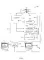
- FIG. 2is a block diagram illustrating typical components utilized at the headend of the present system 100 .
- multicast contentsuch as pay television or video-on-demand data originating from non IP-formatted sources 107 is encoded (formatted) and encapsulated (packetized) by equipment 106 that is well-known in the art.
- Routers 208 / 1 and 208 / 2 , and cache memory 209are employed to direct and temporarily store data being transferred between data sources 102 / 107 and switch 105 .
- Host computer 108may be used to control and monitor various aspects of system operation including setting up membership in multicast groups, as explained below with respect to FIG. 7 .
- downstream transmitter 104 Tsends a plurality of unicast signals on channels 101 U and a single multicast channel 101 M to a plurality of subscriber sites 120 via antenna 103 .
- antenna 103is replaced by an Internet link or other network, as described below with respect to FIG. 7 .
- a plurality of channels of IP-formatted data 111 from various subscriber sites 120are received by upstream receiver 104 R.
- Return channel server 212is used for processing upstream data from subscriber sites 120 , for example, to determine subscriber identities and for scheduling subscriber-requested programming.
- headend 110schedules a wide variety of data services which include full-duplex or asymmetrical transmission of interactive, on-demand, pay-per-view video services or other programming content, audio file transfer, etc.
- a subscriber unit 300(described below with respect to FIG. 3 ) allows the multicast transmission to pass through to the subscriber's local network. Otherwise, the multicast transmission channel(s) are ignored by the subscriber unit.
- the headendauthorizes access to the requested broadcast stream(s) using a subscriber's permissions profile by initiating a join request which is subsequently authenticated and authorized by server 212 using standard AAA (authentication, authorization, accounting) mechanisms such as RADIUS.
- AAAauthentication, authorization, accounting
- FIG. 3is a block diagram illustrating components used for demodulating and distributing a received multi-channel signal at a subscriber site 120 A in an exemplary embodiment of the present system.
- each subscriber site 120 Ais provided with a device (a ‘subscriber unit’) 300 which receives RF signals 101 M and 101 U on different frequencies.
- the exemplary embodiment of FIG. 3includes a television set 312 and a PC 112 connected to subscriber unit 300 via an Ethernet link 325 / 326 / 327 .
- any IP-addressable devicemay be used in lieu of TV 312 or PC 112 .
- transceiver 114receives signal 101 comprising a plurality of unicast channels 101 U and a multicast channel 101 M.
- the received signalsare simultaneously and dynamically demodulated and interleaved over a single local network interface 325 connected to one or more IP enabled devices 112 / 312 .
- Subscriber unit 300is programmed as to which two downstream channels 101 M/ 101 U it will be demodulating. The two signals are selected by transceiver 114 which also controls when it will pass the information on through to the local network 325 / 326 / 327 . Subscriber unit 300 multiplexes the received data from both downstream channels onto the local subscriber network.
- Local network 325 / 326 / 327typically employs an Ethernet bus, but the network could, alternatively, be any type of local network, including wireless LANs such as those conforming to the IEEE draft standard 802.11.
- the plurality of unicast signals on channels 101 Umay, optionally, be filtered by a programmable filter 324 in transceiver 114 , so that the only unicast channel sent to ethernet link 325 is the channel containing the unicast information intended for the specific subscriber site 120 A.
- a mechanismsuch as a digital filter (having an encoded subscriber ID, or using a subscriber IP address) may be provided for ensuring that a given subscriber does not have access to other subscriber's unicast channels.
- the plurality of unicast channels 101 Uare transmitted to all subscribers, a given subscriber PC or TV receives only the unicast subchannel intended for that specific subscriber, as filtered by transceiver filter 324 , if present, and which has an IP address that matches the IP address of the subscriber site equipment.
- Each subscriber sitehas a unique identifier included in the IP address that is encoded in each transmission from headend 110 .
- PC (or TV) 112 and set-top box 323thus receive only the signal having the IP destination address that matches the IP address used by the IP-addressable set-top box 323 or the subscriber's network interface card (‘NIC’, not shown) in PC 112 .
- NICnetwork interface card
- Transceiver 114also receives multicast transmissions on an RF channel that is separate from the unicast transmissions.
- an IP-addressable recipientPC 112 or set-top box 323
- NICnetwork interface card
- signal 101After being received by transceiver 114 , signal 101 , containing the unicast signal 101 U and the multicast signal 101 M, is sent to demodulators 322 A and 322 B, which demodulate the received signal into unicast signal 101 U and multicast signal 101 M, and multiplex the digital signals onto the Ethernet link 325 .
- Demodulators 322 A and 322 Bmay be a single device, i.e., a dual channel demodulator.
- Ethernet link 325is then used to deliver the digital signals 101 U and 101 M to PC 112 and set-top box 323 , respectively, via Ethernet connections 326 and 327 .
- Modulator 321is used for modulation of signals (e.g., Internet upstream transmissions or on-demand requests) sent from PC 112 upstream to headend 110 via channel 111 U.
- each subscriberto have the capability of, for example, receiving a video stream concurrent with many other subscribers while simultaneously interacting uniquely with the Internet or other data network.
- a number of subscribersmay therefore simultaneously share the same interactive transmission medium with the ability to opt-in to a second service simultaneous with a primary service without interruption or degradation of the primary service.
- FIG. 4is a block diagram illustrating subscriber site components used in distributing a received multi-channel signal at a subscriber site 120 B in an alternative embodiment of the present system.
- two PCs 112 / 1 and 112 / 2are coupled to subscriber unit 300 .
- device 112 / 1can be a television set, in which case video interface is the same as set-top box 323 shown in FIG. 3 .
- Subscriber unit 300comprises transceiver 114 , modulator 321 , demodulators 322 A and 322 B, storage device 401 , and Ethernet bus 325 .
- PC 1 (or TV) 112 / 1 and PC 2 112 / 2are connected to the components in subscriber unit 300 via Ethernet bus 325 .
- transceiver 114receives signal 101 comprising a unicast channel 101 U and a multicast channel 101 M. These signals are demodulated and placed on Ethernet bus 325 , as explained above with respect to FIG. 3 .
- a video interface card 402converts received digital television signal into a signal appropriate for displaying video images on the device's video monitor.
- Storage device 401is a disk drive, rewriteable DVD (digital Video disk), or the like, for storing video and audio information. Storage device 401 may be employed to effect time-shifting of programming by storing a received program and playing back the stored program at a later time.
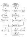
- FIG. 5is a flowchart illustrating basic operation of the present system.
- unicast and multicast dataare separately packetized and encoded in IP format by encoding equipment 106 at headend 110 .
- unicast datasuch as an Internet transmission
- Multicast datais sent from headend 110 via channel 101 M, at step 510 , which occurs simultaneously with the transmission of unicast data.
- both unicast and multicast channelsare received at each of the subscriber sites 120 / 120 A/ 120 B (hereinafter generically referred to by reference number 120 *), at step 515 .
- the data on channels 101 U and 101 Mis then demodulated at the subscriber sites, and at step 525 , the demodulated data is multiplexed onto an Ethernet bus.
- step 530if a particular subscriber site has ‘joined’ the multicast transmission (as explained below with respect to FIG. 7 ), then at step 535 , the multicast data is received by the appropriate subscriber site PC/TV. At step 540 , unicast data is received by the PC or set-top box having the IP address encoded in channel 101 U.
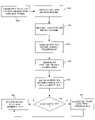
- FIG. 6is a flowchart illustrating an exemplary sequence of steps performed by the present system in asynchronously processing subscriber requests for audio, video, or other information via a unicast channel and a multicast channel.
- the blocks to the left of the vertical dotted line in FIG. 6illustrate steps preformed with respect to the transmission of unicast data, and the blocks to the right of the dotted line illustrate the transmission of multicast data.
- the data on the unicast channelis not interleaved with the data on the multicast channel at the RF level.
- the content or data contained on both channelsis interleaved at the local network level by subscriber unit 300 , as described above.
- datais received at headend 110 from a subscriber site 120 *, via one of the upstream channels 111 .
- the received subscriber datais ‘external’ data, such as Internet data (i.e., data not intended for processing by the headend facility)
- the datais forwarded to the appropriate destination. Otherwise, the received subscriber data is processed by return channel server 212 , at step 625 .
- return channel server 212If a particular subscriber is transmitting and receiving external data, e.g., via the Internet, then data (if any) is received from Internet access or other external data source 102 , at step 620 .
- new dataeither from external source 102 or from return channel server 212 , is sent to the subscriber site via the appropriate unicast channel 101 U.
- Multicast datais transmitted from headend 110 simultaneously and asynchronously relative to the transmission of unicast data. Detailed aspects of multicast operation are described below with respect to FIG. 7 .
- a subscriber request for audio, video, or other programmingis received via channel 111 by return channel server 212 .
- the subscriberis included in the appropriate group, and at step 665 , the subscriber request for programming is sent via channel 111 to headend 110 .
- the subscriber requestis then received and processed by return channel server 212 .
- the program informationis transmitted via channel 101 M to a plurality of subscriber sites 120 .
- each subscriber site that has joined the present multicast groupallows the multicast program to be passed through the appropriate PC 112 * or set-top box 323 . Because the subscriber unit 300 and/or client software in a PC 112 is multicast enabled, the subscriber either receives or ignores the multicast data. Even if the data on channel 101 M is not a standards-based multicast, (e.g., if a proprietary transmission protocol and client software are employed) the above-described process still applies. It also allows unicast data to flow simultaneously on the same ethernet link.
- step 685if the subscriber site has scheduled the program for the present time, then the program is ‘played’ (e.g., viewed, if the program is a movie), at step 695 . If the subscriber site has scheduled the program for a later time, then at step 690 , the program is stored on storage device 401 for subsequent playback.
- FIG. 7is a network diagram, illustrating multicast operation of the present system in an alternative embodiment.
- an Internet link or other network 700such as a cable network, replaces antenna 103 and transmitter/receiver 104 shown with respect to the previously described embodiments.
- Multicastingis essentially the transmission of a message to a group of receivers (comprising a subnet of a network) that are identified and selected via one or more routers or other devices that selectively forward the message. As described in detail below, each of these receivers must indicate whether or not it wants to receive the message.
- a multicast networkforwards multicast data only to network subnets that have at least one receiver that has indicated it wants to receive a particular message.
- each receiver 120 *may be viewed as comprising a subscriber unit 300 and a PC 112 * or set-top box 323 and associated client application located at a subscriber site 120 .
- Each receiver shown in FIG. 7is thus, in effect, a subscriber site 120 *.
- signal 101 Mis transmitted in an IP multicast format in each of the embodiments described herein, the transmission mechanism employed by the system shown in FIGS. 1-4 is, technically, a broadcast that is selectively ignored by certain subscriber units.
- the networking embodiment shown in FIG. 7includes sub-networks which allow the system to take advantage of the selective sub-networking that distinguishes multicast over broadcast.
- both unicast channels 101 U and multicast channel 101 Mare directed to the appropriate destination subscriber sites 120 * by routers 701 and 702 .
- either subscriber site B 1 or B 2has (or have) requested to receive a particular multicast transmission and joined the appropriate multicast group.
- the requested multicast transmissionis selectively forwarded via routers 701 and 702 and paths 705 and 706 to both subscriber sites B 1 and B 2 , since both of these sites are on the same subnetwork of router B. Note that network bandwidth is conserved by avoiding transmission of the multicast data to any receivers (sites) other than those that are located on a subnetwork wherein at least one subscriber has indicated that it wants to receive a particular multicast transmission.
- unicast datais transmitted and received by each intended recipient on network 700 simultaneously along with the selected transmission of multicast data, regardless of the subnetwork on which a particular unicast data recipient is located.
- unicast datamay be transmitted over network 700 simultaneously to subscriber sites A 1 , B 1 , and C 2 simultaneously with the multicast transmission to sites B 1 and B 2 in the present example.
- IGMPInternet Group Management Protocol
- IP host 108the Internet Group Management Protocol
- IP host 108the Internet Group Management Protocol
- Multicast protocols other than IGMPfor example, PIM, PGM, MBGP, IDMR, MSDP, or SSM, may also be used to implement the multicast aspect of the present system.
- multicast routers A and B( 701 and 702 ) send Host Membership Query messages to discover which host groups have members on their attached local networks.
- a multicast routerkeeps a list of multicast group memberships for each attached network, and a timer for each membership.
- a clienti.e., a software application running on a subscriber's PC 112 * or set-top box 323 joins a multicast group by sending an IGMP membership report message.
- IGMPis common to all multicast router protocols, and isolates end users from the routing protocol in use.
- the clientjoins a multicast group by initiating two processes.
- an IGMP messagei.e., a join request is sent to the client's local router to inform the router that the client wants to receive data sent to the group.
- the IGMP messagesent to a ‘local router’ (e.g., router 208 / 1 ) at the headend 110 .
- the subscriber's appropriate PC 112 * or set-top box 323sets its IP process and network interface card (NIC) to receive the multicast on the group's address and port.
- Multicast addressesare Class D IP addresses ranging from 224.0.0.0 to 239.255.255.255.
- Class D IP addressesmap automatically to IEEE-802 Ethernet multicast addresses, which simplifies the implementation of IP multicasting on Ethernet.
- an Ethernet modulereceives packets addressed to the Ethernet multicast addresses that correspond to the host's IP host group addresses. The Ethernet module listens on an arbitrary number of Ethernet multicast addresses, which may be accomplished by “opening up” the address filter to accept all multicast packets during those periods when the number of addresses exceeds the limit of the filter.
- the subscriber PC or set-top box client softwarethen correlates the program selected by the subscriber with a specific group ID (previously sent to the subscriber with, for example, a program list).
- the subscriber clientas well as all intermediate routers (if any) in the path between the client and the headend begin passing the requested multicast stream through where it is interleaved with other data from the unicast channel onto the subscriber's ethernet bus 325 . If a movie or other programming is already in progress, then the client simply allows those packets to pass (much like tuning a TV to a particular channel).
- a requestis required to initiate transmission of the movie if no one else on the subscriber's subnetwork has done so.
- the program requestis sent to the headend 110 , where it is processed by return channel server 212 .
- the multicast channelis then received, demodulated and multiplexed onto an ethernet connection for receipt by all devices connected to the subscriber's local (e.g., Ethernet) network, as described with respect to FIGS. 3-5 .
- the local routerstops sending data to the client's subnetwork, thereby freeing bandwidth on that portion of the network.
- the process of leaving a groupis not shown on the flowchart in FIG. 6 , but this can be accomplished either explicitly by the client, or by a local router, via time-out of a timer.
Landscapes
- Engineering & Computer Science (AREA)
- Signal Processing (AREA)
- Multimedia (AREA)
- Physics & Mathematics (AREA)
- Astronomy & Astrophysics (AREA)
- General Physics & Mathematics (AREA)
- Computer Networks & Wireless Communication (AREA)
- Two-Way Televisions, Distribution Of Moving Picture Or The Like (AREA)
- Data Exchanges In Wide-Area Networks (AREA)
Abstract
Description
Claims (14)
Priority Applications (1)
| Application Number | Priority Date | Filing Date | Title |
|---|---|---|---|
| US10/020,030US7500261B1 (en) | 2001-10-30 | 2001-10-30 | Multi-point multi-channel data distribution system |
Applications Claiming Priority (1)
| Application Number | Priority Date | Filing Date | Title |
|---|---|---|---|
| US10/020,030US7500261B1 (en) | 2001-10-30 | 2001-10-30 | Multi-point multi-channel data distribution system |
Publications (1)
| Publication Number | Publication Date |
|---|---|
| US7500261B1true US7500261B1 (en) | 2009-03-03 |
Family
ID=40385495
Family Applications (1)
| Application Number | Title | Priority Date | Filing Date |
|---|---|---|---|
| US10/020,030Expired - LifetimeUS7500261B1 (en) | 2001-10-30 | 2001-10-30 | Multi-point multi-channel data distribution system |
Country Status (1)
| Country | Link |
|---|---|
| US (1) | US7500261B1 (en) |
Cited By (25)
| Publication number | Priority date | Publication date | Assignee | Title |
|---|---|---|---|---|
| US20050141539A1 (en)* | 2003-12-24 | 2005-06-30 | Hamilton Christopher W. | Network-based data distribution system |
| US20050175070A1 (en)* | 2004-01-20 | 2005-08-11 | Grob Matthew S. | Synchronized broadcast/multicast communication |
| US20050273833A1 (en)* | 2004-05-14 | 2005-12-08 | Nokia Corporation | Customized virtual broadcast services |
| US20060015928A1 (en)* | 2003-06-30 | 2006-01-19 | World Wide Packets, Inc. | Multicast services control system and method |
| US20060140207A1 (en)* | 2004-12-29 | 2006-06-29 | Eschbach Jeffrey T | Selectively receiving data in a multicast environment |
| US20060159093A1 (en)* | 2005-01-20 | 2006-07-20 | Samsung Electronics Co.; Ltd | Broadcast splitter enabling selective transmission in real time |
| US20060184431A1 (en)* | 2000-04-12 | 2006-08-17 | Music Choice | Media content delivery systems and methods |
| US20060239289A1 (en)* | 2005-04-21 | 2006-10-26 | Danyang Zheng | Method and apparatus for determining information associated with a particular multicast channel in a multicast network |
| US20060285483A1 (en)* | 2005-06-15 | 2006-12-21 | Samsung Electronics Co., Ltd. | Apparatus and method for multiplexing broadcast and unicast traffic in a multi-carrier wireless network |
| US20070002724A1 (en)* | 2005-06-15 | 2007-01-04 | Samsung Electronics Co., Ltd. | Apparatus and method for broadcast superposition and cancellation in a multi-carrier wireless network |
| US20070282708A1 (en)* | 2000-04-12 | 2007-12-06 | Music Choice | Cross Channel Delivery System and Method |
| US20080198785A1 (en)* | 2004-05-01 | 2008-08-21 | Neocific, Inc. | Methods and Apparatus for Cellular Broadcasting and Communication System |
| US20080256581A1 (en)* | 2005-12-08 | 2008-10-16 | Byung-Tak Lee | Apparatus and Method for Interactive Multimedia Service in Access Network |
| US20090028109A1 (en)* | 2005-06-09 | 2009-01-29 | Haiming Huang | Methods and apparatus for power efficient broadcasting and communication systems |
| US20090316709A1 (en)* | 2008-05-21 | 2009-12-24 | Polcha Andrew J | Devices and methods for a virtual internet protocol television (viptv) |
| US20100299693A1 (en)* | 2005-08-19 | 2010-11-25 | At&T Intellectual Property I, L.P. | System and method of managing video streams to a set top box |
| US20110085538A1 (en)* | 2009-10-08 | 2011-04-14 | Sony Corporation | System and method for operating a device over multiple frequency bands |
| US20120027411A1 (en)* | 2005-12-20 | 2012-02-02 | Huawei Technologies Co., Ltd. | Passive optical network user terminal and method of power supply control and power supply state reporting for the same |
| US20120131617A1 (en)* | 2009-05-25 | 2012-05-24 | Unitron | Control over coax for tv signal reception devices |
| US20140181253A1 (en)* | 2008-09-08 | 2014-06-26 | Sling Media Inc. | Systems and methods for projecting images from a computer system |
| US8831110B2 (en) | 2011-07-20 | 2014-09-09 | James D. Ocon | Electronic news gathering method and system for the prioritized transmission of data |
| US20150026294A1 (en)* | 2013-07-18 | 2015-01-22 | Open Text S.A. | Delivery pacing systems and methods |
| WO2016048540A1 (en)* | 2014-09-26 | 2016-03-31 | Intel Corporation | Content distribution |
| US9853761B2 (en)* | 2010-12-20 | 2017-12-26 | Telefonaktiebolaget Lm Ericsson (Publ) | Passive optical network arrangement and method |
| US11483832B1 (en) | 2010-09-28 | 2022-10-25 | Neo Wireless Llc | Methods and apparatus for flexible use of frequency bands |
Citations (16)
| Publication number | Priority date | Publication date | Assignee | Title |
|---|---|---|---|---|
| US5706048A (en) | 1995-04-24 | 1998-01-06 | Motorola, Inc. | Wireless digital data access system and method |
| US6069621A (en)* | 1994-05-10 | 2000-05-30 | Schupak; Donald | Distributed computer system for providing audio, video, and information signals to plural modules throughout a home |
| US6072784A (en)* | 1997-07-25 | 2000-06-06 | At&T Corp. | CDMA mobile station wireless transmission power management with adaptive scheduling priorities based on battery power level |
| US6088346A (en)* | 1996-09-27 | 2000-07-11 | U.S. Philips Corporation | Local area network with transceiver |
| US6124878A (en)* | 1996-12-20 | 2000-09-26 | Time Warner Cable, A Division Of Time Warner Enterainment Company, L.P. | Optimum bandwidth utilization in a shared cable system data channel |
| US6201536B1 (en)* | 1992-12-09 | 2001-03-13 | Discovery Communications, Inc. | Network manager for cable television system headends |
| US20010051037A1 (en)* | 2000-03-08 | 2001-12-13 | General Instrument Corporation | Personal versatile recorder: enhanced features, and methods for its use |
| US6393158B1 (en)* | 1999-04-23 | 2002-05-21 | Monkeymedia, Inc. | Method and storage device for expanding and contracting continuous play media seamlessly |
| US20020062483A1 (en)* | 2000-11-20 | 2002-05-23 | Masayuki Ishizaki | Two-way communication system |
| US6411616B1 (en)* | 1996-11-12 | 2002-06-25 | Starguide Digital Networks, Inc. | High bandwidth broadcast system having localized multicast access to broadcast content |
| US20020124262A1 (en)* | 1999-12-01 | 2002-09-05 | Andrea Basso | Network based replay portal |
| US20030046706A1 (en)* | 2001-08-29 | 2003-03-06 | Rakib Selim Shlomo | Active cable modem outside customer premises servicing multiple customer premises |
| US6763025B2 (en)* | 2001-03-12 | 2004-07-13 | Advent Networks, Inc. | Time division multiplexing over broadband modulation method and apparatus |
| US6857132B1 (en)* | 2000-01-14 | 2005-02-15 | Terayon Communication Systems, Inc. | Head end multiplexer to select and transmit video-on-demand and other requested programs and services |
| US6930788B1 (en)* | 1999-07-20 | 2005-08-16 | Canon Kabushiki Kaisha | Secure printing over cable network to home printer |
| US7012891B1 (en)* | 2000-12-28 | 2006-03-14 | Cisco Technology, Inc. | Method and apparatus for applying quality of service to multicast streams transmitted in a cable network |
- 2001
- 2001-10-30USUS10/020,030patent/US7500261B1/ennot_activeExpired - Lifetime
Patent Citations (16)
| Publication number | Priority date | Publication date | Assignee | Title |
|---|---|---|---|---|
| US6201536B1 (en)* | 1992-12-09 | 2001-03-13 | Discovery Communications, Inc. | Network manager for cable television system headends |
| US6069621A (en)* | 1994-05-10 | 2000-05-30 | Schupak; Donald | Distributed computer system for providing audio, video, and information signals to plural modules throughout a home |
| US5706048A (en) | 1995-04-24 | 1998-01-06 | Motorola, Inc. | Wireless digital data access system and method |
| US6088346A (en)* | 1996-09-27 | 2000-07-11 | U.S. Philips Corporation | Local area network with transceiver |
| US6411616B1 (en)* | 1996-11-12 | 2002-06-25 | Starguide Digital Networks, Inc. | High bandwidth broadcast system having localized multicast access to broadcast content |
| US6124878A (en)* | 1996-12-20 | 2000-09-26 | Time Warner Cable, A Division Of Time Warner Enterainment Company, L.P. | Optimum bandwidth utilization in a shared cable system data channel |
| US6072784A (en)* | 1997-07-25 | 2000-06-06 | At&T Corp. | CDMA mobile station wireless transmission power management with adaptive scheduling priorities based on battery power level |
| US6393158B1 (en)* | 1999-04-23 | 2002-05-21 | Monkeymedia, Inc. | Method and storage device for expanding and contracting continuous play media seamlessly |
| US6930788B1 (en)* | 1999-07-20 | 2005-08-16 | Canon Kabushiki Kaisha | Secure printing over cable network to home printer |
| US20020124262A1 (en)* | 1999-12-01 | 2002-09-05 | Andrea Basso | Network based replay portal |
| US6857132B1 (en)* | 2000-01-14 | 2005-02-15 | Terayon Communication Systems, Inc. | Head end multiplexer to select and transmit video-on-demand and other requested programs and services |
| US20010051037A1 (en)* | 2000-03-08 | 2001-12-13 | General Instrument Corporation | Personal versatile recorder: enhanced features, and methods for its use |
| US20020062483A1 (en)* | 2000-11-20 | 2002-05-23 | Masayuki Ishizaki | Two-way communication system |
| US7012891B1 (en)* | 2000-12-28 | 2006-03-14 | Cisco Technology, Inc. | Method and apparatus for applying quality of service to multicast streams transmitted in a cable network |
| US6763025B2 (en)* | 2001-03-12 | 2004-07-13 | Advent Networks, Inc. | Time division multiplexing over broadband modulation method and apparatus |
| US20030046706A1 (en)* | 2001-08-29 | 2003-03-06 | Rakib Selim Shlomo | Active cable modem outside customer premises servicing multiple customer premises |
Cited By (70)
| Publication number | Priority date | Publication date | Assignee | Title |
|---|---|---|---|---|
| US20130014189A1 (en)* | 2000-04-12 | 2013-01-10 | Music Choice | Media Content Delivery Systems and Methods |
| US8332276B2 (en) | 2000-04-12 | 2012-12-11 | Music Choice | Cross channel delivery system and method |
| US8271341B2 (en)* | 2000-04-12 | 2012-09-18 | Music Choice | Media content delivery systems and methods |
| US20070282708A1 (en)* | 2000-04-12 | 2007-12-06 | Music Choice | Cross Channel Delivery System and Method |
| US8751324B2 (en)* | 2000-04-12 | 2014-06-10 | Music Choice | Media content delivery systems and methods |
| US9171325B2 (en) | 2000-04-12 | 2015-10-27 | Music Choice | Cross channel delivery system and method |
| US20060184431A1 (en)* | 2000-04-12 | 2006-08-17 | Music Choice | Media content delivery systems and methods |
| US8046809B2 (en)* | 2003-06-30 | 2011-10-25 | World Wide Packets, Inc. | Multicast services control system and method |
| US20060015928A1 (en)* | 2003-06-30 | 2006-01-19 | World Wide Packets, Inc. | Multicast services control system and method |
| US20050141539A1 (en)* | 2003-12-24 | 2005-06-30 | Hamilton Christopher W. | Network-based data distribution system |
| US7830879B2 (en)* | 2003-12-24 | 2010-11-09 | Agere Systems Inc. | Network-based data distribution system |
| US8363697B2 (en) | 2004-01-20 | 2013-01-29 | Qualcomm Incorporated | Synchronized broadcast/multicast communication |
| US8619835B2 (en)* | 2004-01-20 | 2013-12-31 | Qualcomm Incorporated | Synchronized broadcast/multicast communication |
| US20050175070A1 (en)* | 2004-01-20 | 2005-08-11 | Grob Matthew S. | Synchronized broadcast/multicast communication |
| US20110134824A1 (en)* | 2004-01-20 | 2011-06-09 | Qualcomm Incorporated | Synchronized broadcast/multicast communication |
| US20110134967A1 (en)* | 2004-01-20 | 2011-06-09 | Qualcomm Incorporated | Synchronized broadcast/multicast communication |
| US20110134823A1 (en)* | 2004-01-20 | 2011-06-09 | Qualcomm Incorporated | Synchronized broadcast/multicast communication |
| US8737538B2 (en) | 2004-01-20 | 2014-05-27 | Qualcomm Incorporated | Synchronized broadcast/multicast communication |
| US8582621B2 (en) | 2004-01-20 | 2013-11-12 | Qualcomm Incorporated | Synchronized broadcast/multicast communication |
| US20080198785A1 (en)* | 2004-05-01 | 2008-08-21 | Neocific, Inc. | Methods and Apparatus for Cellular Broadcasting and Communication System |
| US8089911B2 (en)* | 2004-05-01 | 2012-01-03 | Neocific, Inc. | Methods and apparatus for cellular broadcasting and communication system |
| US20050273833A1 (en)* | 2004-05-14 | 2005-12-08 | Nokia Corporation | Customized virtual broadcast services |
| US7801068B2 (en)* | 2004-12-29 | 2010-09-21 | Motorola, Inc. | Selectively receiving data in a multicast environment |
| US20060140207A1 (en)* | 2004-12-29 | 2006-06-29 | Eschbach Jeffrey T | Selectively receiving data in a multicast environment |
| US20060159093A1 (en)* | 2005-01-20 | 2006-07-20 | Samsung Electronics Co.; Ltd | Broadcast splitter enabling selective transmission in real time |
| US8374115B2 (en) | 2005-03-25 | 2013-02-12 | Neocific, Inc. | Methods and apparatus for cellular broadcasting and communication system |
| US8634375B2 (en) | 2005-03-25 | 2014-01-21 | Neocific, Inc. | Methods and apparatus for cellular broadcasting and communication system |
| US11658838B2 (en) | 2005-03-25 | 2023-05-23 | Neo Wireless Llc | Broadcast signal indicating one or more subframe configurations |
| US11296900B2 (en) | 2005-03-25 | 2022-04-05 | Neo Wireless Llc | Broadcast signal indicating one or more subframe configurations |
| US11283640B2 (en) | 2005-03-25 | 2022-03-22 | Neo Wireless Llc | Bitmap based resource scheduling in a wireless network |
| US11115229B2 (en) | 2005-03-25 | 2021-09-07 | Neo Wireless Llc | Method and apparatus for periodic and polled channel quality feedback |
| US10931469B2 (en) | 2005-03-25 | 2021-02-23 | Neo Wireless Llc | Methods and apparatus for cellular broadcasting and communication system |
| US10044517B2 (en)* | 2005-03-25 | 2018-08-07 | Neocific, Inc. | Methods and apparatus for cellular broadcasting and communication system |
| US20140133444A1 (en)* | 2005-03-25 | 2014-05-15 | Neocific, Inc. | Methods and apparatus for cellular broadcasting and communication system |
| US7710983B2 (en)* | 2005-04-21 | 2010-05-04 | Cisco Technology, Inc. | Method and apparatus for determining information associated with a particular multicast channel in a multicast network |
| US20060239289A1 (en)* | 2005-04-21 | 2006-10-26 | Danyang Zheng | Method and apparatus for determining information associated with a particular multicast channel in a multicast network |
| US20090028109A1 (en)* | 2005-06-09 | 2009-01-29 | Haiming Huang | Methods and apparatus for power efficient broadcasting and communication systems |
| US12284049B2 (en) | 2005-06-09 | 2025-04-22 | Neo Wireless Llc | Methods and apparatus for power efficient broadcasting and communication systems |
| US8155098B2 (en) | 2005-06-09 | 2012-04-10 | Neocific, Inc. | Methods and apparatus for power efficient broadcasting and communication systems |
| US8457081B2 (en) | 2005-06-09 | 2013-06-04 | Neocific, Inc. | Methods and apparatus for power efficient broadcasting and communication systems |
| US8934394B2 (en) | 2005-06-09 | 2015-01-13 | Neocific, Inc. | Methods and apparatus for power efficient broadcasting and communication systems |
| US11979248B2 (en) | 2005-06-09 | 2024-05-07 | Neo Wireless Llc | Method and apparatus for receiving broadcast information in an OFDM communication system |
| US20070002724A1 (en)* | 2005-06-15 | 2007-01-04 | Samsung Electronics Co., Ltd. | Apparatus and method for broadcast superposition and cancellation in a multi-carrier wireless network |
| US20060285483A1 (en)* | 2005-06-15 | 2006-12-21 | Samsung Electronics Co., Ltd. | Apparatus and method for multiplexing broadcast and unicast traffic in a multi-carrier wireless network |
| US7894818B2 (en)* | 2005-06-15 | 2011-02-22 | Samsung Electronics Co., Ltd. | Apparatus and method for multiplexing broadcast and unicast traffic in a multi-carrier wireless network |
| US8799978B2 (en)* | 2005-08-19 | 2014-08-05 | At&T Intellectual Property I, L.P. | System and method of managing video streams to a set top box |
| US20100299693A1 (en)* | 2005-08-19 | 2010-11-25 | At&T Intellectual Property I, L.P. | System and method of managing video streams to a set top box |
| US20080256581A1 (en)* | 2005-12-08 | 2008-10-16 | Byung-Tak Lee | Apparatus and Method for Interactive Multimedia Service in Access Network |
| US20170126350A1 (en)* | 2005-12-20 | 2017-05-04 | Huawei Technologies Co., Ltd. | Passive optical network user terminal and method of power supply control and power supply state reporting for the same |
| US8913890B2 (en) | 2005-12-20 | 2014-12-16 | Huawei Technologies Co., Ltd. | Passive optical network user terminal and method of power supply control and power supply state reporting for the same |
| US8452178B2 (en)* | 2005-12-20 | 2013-05-28 | Huawei Technologies Co., Ltd. | Passive optical network user terminal and method of power supply control and power supply state reporting for the same |
| US20120027411A1 (en)* | 2005-12-20 | 2012-02-02 | Huawei Technologies Co., Ltd. | Passive optical network user terminal and method of power supply control and power supply state reporting for the same |
| US9553690B2 (en) | 2005-12-20 | 2017-01-24 | Huawei Technologies Co., Ltd. | Passive optical network user terminal and method of power supply control and power supply state reporting for the same |
| US8170037B2 (en)* | 2008-05-21 | 2012-05-01 | Polcha Andrew J | Devices and methods for a virtual internet protocol television (VIPTV) |
| US20090316709A1 (en)* | 2008-05-21 | 2009-12-24 | Polcha Andrew J | Devices and methods for a virtual internet protocol television (viptv) |
| US20140181253A1 (en)* | 2008-09-08 | 2014-06-26 | Sling Media Inc. | Systems and methods for projecting images from a computer system |
| US9600222B2 (en)* | 2008-09-08 | 2017-03-21 | Sling Media Inc. | Systems and methods for projecting images from a computer system |
| US20120131617A1 (en)* | 2009-05-25 | 2012-05-24 | Unitron | Control over coax for tv signal reception devices |
| US20110085538A1 (en)* | 2009-10-08 | 2011-04-14 | Sony Corporation | System and method for operating a device over multiple frequency bands |
| US11510201B2 (en) | 2010-09-28 | 2022-11-22 | Neo Wireless Llc | Methods and apparatus for flexible use of frequency bands |
| US11985646B2 (en) | 2010-09-28 | 2024-05-14 | Neo Wireless Llc | Methods and apparatus for flexible use of frequency bands |
| US11483832B1 (en) | 2010-09-28 | 2022-10-25 | Neo Wireless Llc | Methods and apparatus for flexible use of frequency bands |
| US11510202B2 (en) | 2010-09-28 | 2022-11-22 | Neo Wireless Llc | Methods and apparatus for flexible use of frequency bands |
| US9853761B2 (en)* | 2010-12-20 | 2017-12-26 | Telefonaktiebolaget Lm Ericsson (Publ) | Passive optical network arrangement and method |
| US8831110B2 (en) | 2011-07-20 | 2014-09-09 | James D. Ocon | Electronic news gathering method and system for the prioritized transmission of data |
| US20150026294A1 (en)* | 2013-07-18 | 2015-01-22 | Open Text S.A. | Delivery pacing systems and methods |
| US10440150B2 (en)* | 2013-07-18 | 2019-10-08 | Open Text Holdings, Inc. | Delivery pacing systems and methods |
| US12212637B2 (en) | 2013-07-18 | 2025-01-28 | Open Text Holdings, Inc. | Delivery pacing systems and methods |
| WO2016048540A1 (en)* | 2014-09-26 | 2016-03-31 | Intel Corporation | Content distribution |
| US9912985B2 (en) | 2014-09-26 | 2018-03-06 | Intel Corporation | Content distribution |
Similar Documents
| Publication | Publication Date | Title |
|---|---|---|
| US7500261B1 (en) | Multi-point multi-channel data distribution system | |
| JP4653888B2 (en) | Logical node identification in information transmission networks | |
| EP1949688B1 (en) | Atomic channel changes in a switched digital video system | |
| US7558870B2 (en) | Multimedia content delivery system | |
| US9800909B2 (en) | Method and apparatus for downloading content using channel bonding | |
| US6584082B1 (en) | Apparatus, method and article of manufacture for transmitting data over a satellite | |
| US9398263B2 (en) | Internet protocol multicast content delivery | |
| US20090022154A1 (en) | Reception device, reception method, and computer-readable medium | |
| US20090052450A1 (en) | Apparatus, system, and method for video delivery using dual multicast streams with one being delayed | |
| CA2572717A1 (en) | Methods and apparatus for efficient ip multicasting in a content-based network | |
| US8717886B2 (en) | Communication device and method of managing communication resources | |
| JP2003087765A (en) | Apparatus for providing viewing information to subscriber terminals | |
| JP2005536141A (en) | IP multicasting system and method using satellite | |
| US8544051B1 (en) | Broadcast solution for cable IPTV | |
| JP2003087766A (en) | Viewing information supplying device to subscriber terminal | |
| WO2005084025A1 (en) | Method and apparatus for optimizing bandwith in broadcast/multicast video systems | |
| CN1338871A (en) | Method for multiplexing tuner in bidirectional cable system for cable TV | |
| KR100725922B1 (en) | Internet Protocol Data Transmission Apparatus and Method Using Existing Transmission System and Broadband Downlink Transmission System in Optical Coaxial Hybrid Network | |
| WO2009026421A1 (en) | Apparatus, system, and method for video delivery using dual multicast streams with one being delayed | |
| EP3588847A1 (en) | Multicast signal transmitting and receiving method and device | |
| KR20090003897A (en) | Broadcast receiver, broadcast signal processing method | |
| KR20080022817A (en) | Apparatus and method for retransmission of broadcast data in IP broadcast system | |
| US20110093611A1 (en) | Network unit, a central distribution control unit and a computer program product | |
| Walsh et al. | Multicast Content Delivery for Mobiles |
Legal Events
| Date | Code | Title | Description |
|---|---|---|---|
| STCF | Information on status: patent grant | Free format text:PATENTED CASE | |
| FPAY | Fee payment | Year of fee payment:4 | |
| FPAY | Fee payment | Year of fee payment:8 | |
| AS | Assignment | Owner name:DEUTSCHE BANK TRUST COMPANY AMERICAS, NEW YORK Free format text:GRANT OF FIRST PRIORITY AND JUNIOR PRIORITY SECURITY INTEREST IN PATENT RIGHTS;ASSIGNOR:SPRINT COMMUNICATIONS COMPANY L.P.;REEL/FRAME:041895/0210 Effective date:20170203 | |
| AS | Assignment | Owner name:SPRINT COMMUNICATIONS COMPANY L.P., KANSAS Free format text:TERMINATION AND RELEASE OF FIRST PRIORITY AND JUNIOR PRIORITY SECURITY INTEREST IN PATENT RIGHTS;ASSIGNOR:DEUTSCHE BANK TRUST COMPANY AMERICAS;REEL/FRAME:052969/0475 Effective date:20200401 Owner name:DEUTSCHE BANK TRUST COMPANY AMERICAS, NEW YORK Free format text:SECURITY AGREEMENT;ASSIGNORS:T-MOBILE USA, INC.;ISBV LLC;T-MOBILE CENTRAL LLC;AND OTHERS;REEL/FRAME:053182/0001 Effective date:20200401 | |
| MAFP | Maintenance fee payment | Free format text:PAYMENT OF MAINTENANCE FEE, 12TH YEAR, LARGE ENTITY (ORIGINAL EVENT CODE: M1553); ENTITY STATUS OF PATENT OWNER: LARGE ENTITY Year of fee payment:12 | |
| AS | Assignment | Owner name:T-MOBILE INNOVATIONS LLC, KANSAS Free format text:ASSIGNMENT OF ASSIGNORS INTEREST;ASSIGNOR:SPRINT COMMUNICATIONS COMPANY L.P.;REEL/FRAME:055604/0001 Effective date:20210303 | |
| AS | Assignment | Owner name:SPRINT SPECTRUM LLC, KANSAS Free format text:RELEASE BY SECURED PARTY;ASSIGNOR:DEUTSCHE BANK TRUST COMPANY AMERICAS;REEL/FRAME:062595/0001 Effective date:20220822 Owner name:SPRINT INTERNATIONAL INCORPORATED, KANSAS Free format text:RELEASE BY SECURED PARTY;ASSIGNOR:DEUTSCHE BANK TRUST COMPANY AMERICAS;REEL/FRAME:062595/0001 Effective date:20220822 Owner name:SPRINT COMMUNICATIONS COMPANY L.P., KANSAS Free format text:RELEASE BY SECURED PARTY;ASSIGNOR:DEUTSCHE BANK TRUST COMPANY AMERICAS;REEL/FRAME:062595/0001 Effective date:20220822 Owner name:SPRINTCOM LLC, KANSAS Free format text:RELEASE BY SECURED PARTY;ASSIGNOR:DEUTSCHE BANK TRUST COMPANY AMERICAS;REEL/FRAME:062595/0001 Effective date:20220822 Owner name:CLEARWIRE IP HOLDINGS LLC, KANSAS Free format text:RELEASE BY SECURED PARTY;ASSIGNOR:DEUTSCHE BANK TRUST COMPANY AMERICAS;REEL/FRAME:062595/0001 Effective date:20220822 Owner name:CLEARWIRE COMMUNICATIONS LLC, KANSAS Free format text:RELEASE BY SECURED PARTY;ASSIGNOR:DEUTSCHE BANK TRUST COMPANY AMERICAS;REEL/FRAME:062595/0001 Effective date:20220822 Owner name:BOOST WORLDWIDE, LLC, KANSAS Free format text:RELEASE BY SECURED PARTY;ASSIGNOR:DEUTSCHE BANK TRUST COMPANY AMERICAS;REEL/FRAME:062595/0001 Effective date:20220822 Owner name:ASSURANCE WIRELESS USA, L.P., KANSAS Free format text:RELEASE BY SECURED PARTY;ASSIGNOR:DEUTSCHE BANK TRUST COMPANY AMERICAS;REEL/FRAME:062595/0001 Effective date:20220822 Owner name:T-MOBILE USA, INC., WASHINGTON Free format text:RELEASE BY SECURED PARTY;ASSIGNOR:DEUTSCHE BANK TRUST COMPANY AMERICAS;REEL/FRAME:062595/0001 Effective date:20220822 Owner name:T-MOBILE CENTRAL LLC, WASHINGTON Free format text:RELEASE BY SECURED PARTY;ASSIGNOR:DEUTSCHE BANK TRUST COMPANY AMERICAS;REEL/FRAME:062595/0001 Effective date:20220822 Owner name:PUSHSPRING, LLC, WASHINGTON Free format text:RELEASE BY SECURED PARTY;ASSIGNOR:DEUTSCHE BANK TRUST COMPANY AMERICAS;REEL/FRAME:062595/0001 Effective date:20220822 Owner name:LAYER3 TV, LLC, WASHINGTON Free format text:RELEASE BY SECURED PARTY;ASSIGNOR:DEUTSCHE BANK TRUST COMPANY AMERICAS;REEL/FRAME:062595/0001 Effective date:20220822 Owner name:IBSV LLC, WASHINGTON Free format text:RELEASE BY SECURED PARTY;ASSIGNOR:DEUTSCHE BANK TRUST COMPANY AMERICAS;REEL/FRAME:062595/0001 Effective date:20220822 |