US7498063B2 - High mass throughput particle generation using multiple nozzle spraying - Google Patents
High mass throughput particle generation using multiple nozzle sprayingDownload PDFInfo
- Publication number
- US7498063B2 US7498063B2US10/889,341US88934104AUS7498063B2US 7498063 B2US7498063 B2US 7498063B2US 88934104 AUS88934104 AUS 88934104AUS 7498063 B2US7498063 B2US 7498063B2
- Authority
- US
- United States
- Prior art keywords
- nozzle
- dispensing
- particles
- structures
- nozzle structures
- Prior art date
- Legal status (The legal status is an assumption and is not a legal conclusion. Google has not performed a legal analysis and makes no representation as to the accuracy of the status listed.)
- Expired - Fee Related, expires
Links
Images


Classifications
- B—PERFORMING OPERATIONS; TRANSPORTING
- B05—SPRAYING OR ATOMISING IN GENERAL; APPLYING FLUENT MATERIALS TO SURFACES, IN GENERAL
- B05B—SPRAYING APPARATUS; ATOMISING APPARATUS; NOZZLES
- B05B1/00—Nozzles, spray heads or other outlets, with or without auxiliary devices such as valves, heating means
- B05B1/14—Nozzles, spray heads or other outlets, with or without auxiliary devices such as valves, heating means with multiple outlet openings; with strainers in or outside the outlet opening
- B—PERFORMING OPERATIONS; TRANSPORTING
- B05—SPRAYING OR ATOMISING IN GENERAL; APPLYING FLUENT MATERIALS TO SURFACES, IN GENERAL
- B05B—SPRAYING APPARATUS; ATOMISING APPARATUS; NOZZLES
- B05B5/00—Electrostatic spraying apparatus; Spraying apparatus with means for charging the spray electrically; Apparatus for spraying liquids or other fluent materials by other electric means
- B05B5/025—Discharge apparatus, e.g. electrostatic spray guns
- B05B5/03—Discharge apparatus, e.g. electrostatic spray guns characterised by the use of gas, e.g. electrostatically assisted pneumatic spraying
- B05B5/032—Discharge apparatus, e.g. electrostatic spray guns characterised by the use of gas, e.g. electrostatically assisted pneumatic spraying for spraying particulate materials
- B—PERFORMING OPERATIONS; TRANSPORTING
- B05—SPRAYING OR ATOMISING IN GENERAL; APPLYING FLUENT MATERIALS TO SURFACES, IN GENERAL
- B05B—SPRAYING APPARATUS; ATOMISING APPARATUS; NOZZLES
- B05B5/00—Electrostatic spraying apparatus; Spraying apparatus with means for charging the spray electrically; Apparatus for spraying liquids or other fluent materials by other electric means
- B05B5/025—Discharge apparatus, e.g. electrostatic spray guns
- B05B5/0255—Discharge apparatus, e.g. electrostatic spray guns spraying and depositing by electrostatic forces only
- B—PERFORMING OPERATIONS; TRANSPORTING
- B05—SPRAYING OR ATOMISING IN GENERAL; APPLYING FLUENT MATERIALS TO SURFACES, IN GENERAL
- B05B—SPRAYING APPARATUS; ATOMISING APPARATUS; NOZZLES
- B05B5/00—Electrostatic spraying apparatus; Spraying apparatus with means for charging the spray electrically; Apparatus for spraying liquids or other fluent materials by other electric means
- B05B5/08—Plant for applying liquids or other fluent materials to objects
- B05B5/087—Arrangements of electrodes, e.g. of charging, shielding, collecting electrodes
- B—PERFORMING OPERATIONS; TRANSPORTING
- B05—SPRAYING OR ATOMISING IN GENERAL; APPLYING FLUENT MATERIALS TO SURFACES, IN GENERAL
- B05B—SPRAYING APPARATUS; ATOMISING APPARATUS; NOZZLES
- B05B7/00—Spraying apparatus for discharge of liquids or other fluent materials from two or more sources, e.g. of liquid and air, of powder and gas
- B05B7/02—Spray pistols; Apparatus for discharge
- B05B7/04—Spray pistols; Apparatus for discharge with arrangements for mixing liquids or other fluent materials before discharge
- B05B7/0408—Spray pistols; Apparatus for discharge with arrangements for mixing liquids or other fluent materials before discharge with arrangements for mixing two or more liquids
- B—PERFORMING OPERATIONS; TRANSPORTING
- B05—SPRAYING OR ATOMISING IN GENERAL; APPLYING FLUENT MATERIALS TO SURFACES, IN GENERAL
- B05B—SPRAYING APPARATUS; ATOMISING APPARATUS; NOZZLES
- B05B7/00—Spraying apparatus for discharge of liquids or other fluent materials from two or more sources, e.g. of liquid and air, of powder and gas
- B05B7/02—Spray pistols; Apparatus for discharge
- B05B7/06—Spray pistols; Apparatus for discharge with at least one outlet orifice surrounding another approximately in the same plane
- B05B7/062—Spray pistols; Apparatus for discharge with at least one outlet orifice surrounding another approximately in the same plane with only one liquid outlet and at least one gas outlet
- B05B7/066—Spray pistols; Apparatus for discharge with at least one outlet orifice surrounding another approximately in the same plane with only one liquid outlet and at least one gas outlet with an inner liquid outlet surrounded by at least one annular gas outlet
- A—HUMAN NECESSITIES
- A61—MEDICAL OR VETERINARY SCIENCE; HYGIENE
- A61F—FILTERS IMPLANTABLE INTO BLOOD VESSELS; PROSTHESES; DEVICES PROVIDING PATENCY TO, OR PREVENTING COLLAPSING OF, TUBULAR STRUCTURES OF THE BODY, e.g. STENTS; ORTHOPAEDIC, NURSING OR CONTRACEPTIVE DEVICES; FOMENTATION; TREATMENT OR PROTECTION OF EYES OR EARS; BANDAGES, DRESSINGS OR ABSORBENT PADS; FIRST-AID KITS
- A61F2/00—Filters implantable into blood vessels; Prostheses, i.e. artificial substitutes or replacements for parts of the body; Appliances for connecting them with the body; Devices providing patency to, or preventing collapsing of, tubular structures of the body, e.g. stents
- A61F2/82—Devices providing patency to, or preventing collapsing of, tubular structures of the body, e.g. stents
- A61F2/86—Stents in a form characterised by the wire-like elements; Stents in the form characterised by a net-like or mesh-like structure
- B—PERFORMING OPERATIONS; TRANSPORTING
- B05—SPRAYING OR ATOMISING IN GENERAL; APPLYING FLUENT MATERIALS TO SURFACES, IN GENERAL
- B05B—SPRAYING APPARATUS; ATOMISING APPARATUS; NOZZLES
- B05B13/00—Machines or plants for applying liquids or other fluent materials to surfaces of objects or other work by spraying, not covered by groups B05B1/00 - B05B11/00
- B05B13/06—Machines or plants for applying liquids or other fluent materials to surfaces of objects or other work by spraying, not covered by groups B05B1/00 - B05B11/00 specially designed for treating the inside of hollow bodies
Definitions
- the present inventionrelates generally to spray apparatus and methods. More particularly, the present invention pertains to multiple nozzle spray methods and apparatus, e.g., multiple nozzle electrospray methods and apparatus.
- microsphere production technologycan produce drugs or pharmaceuticals that can be taken up by cells, e.g., cells in an intestinal or stomach wall or lining, and may cross into the bloodstream. Such uptake or absorption into the cell is determined at least in part by the surface chemistry of the microspheres. Uptake of microspheres containing macromolecules, e.g., encapsulated proteins, has also been demonstrated.
- particlesmay be formed using grinding techniques. Further, for example, it has been described that such particles may be formed by removing solvent from a mixture that includes the active ingredient as it is being sprayed into a stream of air, e.g., hot air drying.
- Electrohydrodynamic sprayinghas been used to produce nanoparticles from, for example, solutions or colloidal suspensions.
- the electrosprayis capable of producing nanoparticles that are 10-100 times smaller than, for example, conventional pneumatic atomization techniques. This size of particles allows product that includes such particles to have 100-10,000 times larger surface area than those produced from the conventional techniques, for a given quantity of spray solution.
- the increased surface areaforms the basis of enabling technology for various important applications. For example, new chemicals being synthesized as future drug products are decreasing in aqueous solubility to such an extent as to present major delivery and development challenges. If the drug products employ nanoparticles rather than macroparticles, the increased surface area results in a significantly greater dissolution rate and/or higher solubility rate. This may allow for superior and/or even enabling drug delivery. Nanoparticle medicine may increase the bioavailability and speed up the response time of the delivered drug. Thus, nanoparticle technology has the potential to significantly impact the pharmaceutical industry.
- particlesare generated that may comprise biologically active material, for example, particles may contain matter such as peptides or large biomolecules such as insulin and/or other pharmaceutical components for enabling delivery of an active component into the blood stream.
- electrohydrodynamic processesare used to produce particles, but primarily are used to produce fibres or fibre fragments.
- electrospray or electrohydrodynamic techniquesfor particle generation
- generally only a single spray-nozzle dispenseris used that can deliver only a small quantity of solution, e.g., a few ⁇ l/min.
- a major challenge and problemis the inability to increase the mass throughput from such an electrospray device that can produce nanoparticles so that electrohydrodynamic techniques can be used to deliver industrial quantities particles for use in various products.
- the present inventionprovides apparatus and methods that produce nanoparticles with high mass throughput, e.g., can produce large quantities of nanoparticles for use in various applications, e.g., pharmaceutical, biological material production for gene therapy, coatings, fabrication processes, etc.
- An electrospraying method of the present inventionmay include one or more of the following features: providing a plurality of nozzle structures, wherein each nozzle structure includes at least one opening defined along a center axis of the nozzle structure and terminating at a dispensing end thereof from which a spray of particles having an electrical charge applied thereto is dispensed; nozzle structures that are separated from adjacent nozzle structures by at least an internozzle distance (L) defined by the distance between center axes of the nozzle structures, wherein the ratio of the internozzle distance (L) to a diameter (D) of the opening at the dispensing end is equal to or greater than 2; dispensing a spray of particles from each of a plurality of nozzle structures by creating a nonuniform electrical field between the dispensing ends from which the sprays are established and an electrode electrically isolated from the dispensing ends; nozzle structures that include a capillary tube comprised of a body portion and a tapered capillary tip at the dispensing end of the capillary tube; nozzle
- An apparatus for electrospraying particlesmay include one or more of the following features: a particle source; a dispensing device configured to receive source material from the particle source, wherein the dispensing device comprises a plurality of nozzle structures; nozzle structures that each include at least one opening defined along a center axis of the nozzle structure and terminating at a dispensing end thereof; nozzle structures that are separated from other adjacent nozzle structures by at least an internozzle distance (L) defined by the distance between center axes of nozzle structures, wherein the ratio of the internozzle distance (L) to a diameter (D) of the opening at the dispensing end is equal to or greater than 2; an electrode isolated from the dispensing end, wherein a nonuniform electrical field is created between the dispensing ends and the electrode such that a spray of particles having an electrical charge applied thereto is dispensed from the dispensing end of each nozzle structure; nozzle structures that include a capillary tube that has a body portion and a tapered capillary
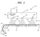
- FIG. 1is a general diagram representative of a particle generator system, e.g., a nanoparticle generator using electrospray techniques, in accordance with the present invention.
- FIG. 2is a general diagrammatical illustration of one embodiment of an electrospraying dispensing device including multiple nozzle structures for use in a particle generator system shown generally in FIG. 1 .
- FIGS. 3A-3Cshow alternate configurations for multiple nozzle structures such as the electrospraying dispensing device shown illustratively in FIG. 2 .
- FIG. 4shows one illustrative embodiment of a circular configuration of multiple nozzle structures shown generally in FIG. 3C .
- FIGS. 5A-5Bshow an illustrative side view diagram of a conical configuration of multiple nozzle structures and an illustrative bottom view of the conical configuration according to the present invention.
- FIG. 6provides a graph showing the voltage required to form a cone jet in a multiple nozzle structure versus the inter-nozzle distance between such nozzle structures for the multiple nozzle configurations shown generally in FIGS. 3A-3C .
- FIG. 7is one illustrative exemplary embodiment of a nozzle structure that may be employed in the illustrative multiple nozzle electrospray dispensing device of FIG. 2 .
- FIG. 8is an alternate embodiment of another nozzle structure using a dual stream technique that may be employed in the multiple nozzle electrospray dispensing device of FIG. 2 .
- FIG. 9shows an alternate configuration of providing multiple electrospray nozzle structures according to the present invention that may be employed in the particle generator system shown generally in FIG. 1 according to the present invention.
- FIG. 10shows a more detailed illustrative embodiment of a nozzle structure employed in the configuration of FIG. 9 .
- FIG. 11shows another alternate configuration for providing multiple electrospray nozzle structures that may be employed in the particle generator system shown generally in FIG. 1 according to the present invention.
- FIG. 12shows a more detailed illustrative embodiment of a nozzle structure employed in the configuration of FIG. 11 .
- FIG. 13is an alternate illustrative embodiment of a multiple nozzle electrospray dispensing device including separation structures provided between nozzles according to the present invention.
- FIGS. 14A-14Bare a side view and a cross sectional view, respectively, of an alternate electrospray dispensing apparatus that may be employed in the multiple nozzle particle generator system of FIG. 1 according to the present invention.
- FIGS. 15A-15Bshow a perspective view and a cross sectional view, respectively, of one illustrative embodiment of a production system employing multiple nozzle structures according to the present invention.
- FIG. 16show yet another alternate configuration of a multiple nozzle structure dispensing apparatus that forms cone jets for spraying particles using air as opposing to electrospray techniques and which may be employed in the particle generator system of FIG. 1 according to the present invention.
- FIG. 17shows a more detailed illustrative embodiment of a nozzle structure of the dispensing device of FIG. 16 .
- FIG. 1Various embodiments of the present invention shall then be described further with reference to FIGS. 2-17 . It will become apparent to one skilled in the art that elements from one embodiment may be used in combination with elements of the other embodiments and that the present invention is not limited to the specific embodiments described herein, but only as described in the accompanying claims.
- the present inventionprovides spraying apparatus and methods that employ multiple nozzle structures for producing multiple sprays of particles, e.g., uniform size nanoparticles.
- Conventional single nozzle spraying apparatus and methodshave been used for producing nanoparticles, however, such apparatus and methods provide a very small throughput that is not suitable for practical production of a large quantity of nanoparticles for applications, e.g., high tech applications such as in the manufacture of medicines, pharmaceuticals, nanostructured materials, etc.
- the present inventionovercomes such limitations and can provide increased throughput in excess of, for example, 1,000 times conventional methods and apparatus, in a confined space. As such, the present invention makes it possible to produce industrial quantity of particles, e.g., nanoparticles, for such varied applications.
- the present inventionis directed to apparatus and methods for generating particles, such as, for example, drug nanoparticles, particles for use in depositing materials on or for forming nanostructures, etc.
- methods and apparatus according to the present inventionallow for 1,000 to 10,000 times higher mass throughput rate than a single nozzle electrospray apparatus such as that previously described in U.S. Pat. No. 6,093,572 Pui, et. al., entitled “Electrospraying Apparatus and Method for Introducing Material into Cells” issued 25 Jul. 2000, and also described in the papers entitled, “Electrospraying of Conducting Liquids for Dispersed Aerosol Generation in the 4 nm to 1.8 ⁇ m Diameter Range” by Chen, et. al., J.
- the present inventionprovides a particle generator system 10 employing a dispensing device 15 to establish multiple sprays of particles 22 .
- the dispensing device 15includes a plurality of nozzle structures 20 which receive source material 17 and establish charged sprays of particles 22 forward thereof, e.g., in the direction of target 12 .
- the dispensing device 15further includes a source holding apparatus 16 for providing the source material 17 to the plurality of nozzle structures 20 under control of control mechanism 14 , e.g. hardware and/or software control.
- Each nozzle structure 20is configured to provide a single spray of particles 22 .
- the multiple sprays 22 established forward of each nozzle structure 20is provided to the target 12 .
- such sprays 22 established forward of each nozzle structure 20provided a spray that has a coverage area “D” when the spray 22 reaches the target 12 .
- the source material 17 held in a source holding apparatus 16may be any source of material which can be sprayed as described according to the present invention herein.
- the source material 17is a fluid composition that may include a solution, a suspension, a microsuspension, an emulsion, a microemulsion, a gel, a hydrosol, or any other like fluid compositions that when sprayed according to the present invention results in the generation of particles.
- such fluid compositionsmay include a solution of dissolved active ingredients, e.g., drug active ingredients, according to one embodiment of the present invention.
- an active ingredientrefers to any component that provides a useful function when provided in particle form, particularly when provided as nanoparticles.
- the present inventionis particularly beneficial for spraying nanoparticles and also is particularly beneficial for spraying particles including biologically active ingredients.
- active ingredientrefers to material which is compatible with and has an effect on the substrate or body with which it is used, such as, for example, drug active ingredients, chemicals elements for forming nanostructures, and elements for film coatings.
- biologically active ingredientor “biologically active material or component,” is a subset of active ingredient, and refers to material which is compatible with and has an effect (which may, for example, be biological, chemical, or biochemical) on the animal or plant with which it is used and includes, for example, medicants such as medicines, pharmaceutical medicines, and veterinary medicines, vaccines, genetic materials such as polynucleic acids, cellular components, and the like, such as those described below.
- nanoparticleincludes solid, partially solid, and gel like droplets and microcapsules which incorporate solid, partially solid, gel like or liquid matter.
- nanoparticlerefers to a particle having a nominal diameter of less than 2000 nm.
- the present inventionis particularly beneficial in spraying nanoparticles having a nominal diameter greater than 1 nanometer (nm), and further preferably having a nominal diameter less than 1000 nm, and more preferably less than 100 nm.
- the present inventionis provided for spraying particles including drug active ingredients, and for simplicity, the remainder of the description herein is primarily provided with respect to such drug active ingredients.
- the present inventionis not limited to only such listed applications because mass throughput of nanoparticles is beneficial in various applications as previously described herein.
- the standard deviation with respect to mean particle size of particles sprayed according to the present inventionis greater than or equal to 2 percent.
- the present inventionis particularly beneficial in spraying nanoparticles that have a standard deviation less than 100 percent, more preferably less than 20 percent, and yet more preferably less than 10 percent.
- target 12comprises a conveyor surface 26 provided around a moving mechanism 27 , e.g., a roller, to provide a manner of collecting a large quantity of particles sprayed thereon.
- a moving mechanism 27e.g., a roller
- the particlesmay be removed from the surface 26 and collected in a collection container 29 for later processing and/or usage.
- such particlesmay be deposited directly onto a surface for coating purposes or for forming a layer or structure on a surface. In such cases, the particles would not be removed from the surface, but would form a part thereof.
- the spray of particles 22may, for example, be a biologically active ingredient or component that may be applied to a surface or area such as, for example, the surface of the skin or a wound or burn or into a cavity, for example, a body cavity.
- the body cavitymay be any body cavity such as the respiratory system of an animal, e.g., a human being.
- Such particlesmay be provided in any number of layers on such a surface or area.
- the biologically active ingredient or componentmay be of a substance that adheres to such a surface or area.
- the target 12may be a container for inhalants such as for inhaling therapy applications.
- the sprays of particles 22would be provided into the container target 12 .
- the spray of materialsmay supply comminuted material to a respiratory system of an animal, e.g., a human.
- Such an inhaling techniquemay provide nanoparticles to a user orally or nasally.
- Biologically active ingredients or components for such applicationsmay be pharmaceutical compounds such as analgesics, antiseptics, antibiotics, antifungals, antibacterials, antiparasitics, debridement agents such as proteolytic enzymes, biological products such as cells, and cytokines for stimulating cytokinetic activity to promote essential cell activities, for example, to stimulate dendritic growth, growth factors such as fibroblast growth factor (FGF), epithelial growth factor (EGF), transforming growth factor (TGF) and others that may be used to promote or otherwise control the sequence of events essential to natural tissue repair, polynucleic acids such as DNA or other genetic material, cells, peptides, or polypeptides, insulin, adjuvants (e.g., an pharmacological agent added to a drug to increase or aid its effect or an immunology agent that increases the antigenic response), immune suppressants, or stimulants, surface binding or surface recognizing agents, surface proteins, and surfactants.
- FGFfibroblast growth factor
- EGFepithelial growth factor
- the particles generatedmay be formed of more than one active ingredient and/or other materials by use of multiple nozzles or openings in each of nozzle structures 20 as further described below.
- a biologically active ingredientmay be completely encapsulated within a polymer using the present invention, e.g., a time release encapsulant.
- the spray of particles 22may also be used in a production process to form an orally ingestible capsule, tablet, etc.
- capsulesmay include particles that provide for time release of the active ingredient.
- coated drug nanoparticlesmay be produced according to the present invention.
- Such drug nanoparticlesmay include active ingredients coated with suitable excipients.
- the present inventionprovides nanoparticles that have a large surface area relative to other particles (e.g., microspheres), such nanoparticles can be taken up by cellular endocytotic mechanisms, and avoid biochemical barriers to absorption of “bare” molecules through the gut wall, e.g., CYP450A-mediated metabolism and P-glycoprotein-mediated efflux pumping of drugs back into the intestinal lumen.
- nanoparticlesas vehicles for drug absorption may also be applied to protein drugs such as insulin, which are generally very poorly absorbed in the gastrointestinal tract. Uptake of larger spheres containing macromolecules has been performed in recent years, and with the reduction in size to nanoparticles, the effect on absorption should be improved for nanoencapsulated proteins.
- excipient materiale.g., excipient powders
- target surface 12e.g., conveyor surface 26
- the sprays of particles 22may then be provided for combination with the excipient material on the target 12 .
- Subsequent processingby any known method or technique, may be used to form a combination of excipient material and active ingredients sprayed thereon into a usable form, e.g., tablets, capsules, etc.
- Excipient materialrefers to any material that may be used with particles generated herein to provide for various functionality, for example, form and consistency of a product in which they are used.
- excipient materialsmay include lactose, starch, methylcellulose, polymer materials, or any other suitable materials that provide for various functions, such as, for example, lubrication, useful flow properties such as those that affect capsule or tablet formation, cohesion, texture, taste properties, transport of active ingredients to absorption sites, prevention from acid attack, or other absorption properties, e.g., time release properties.
- a neurological application for the sprays of charged particles 22is also envisioned, particularly when considering the characteristic growth of neuronal axons to their synaptic target areas.
- the complex circuits of interconnected neurons in adult organismsare formed during embryonic development by the precise elongation of millions or billions or axonal extensions from neuronal cell bodies through embryonic tissues to synaptic targets.
- At the tips of growing axonsare sensitive motile organelles called growth cones, which interactive with environmental molecules (typically glycoproteins) called guidance cues.
- Surface receptors on growth conesdetect the guidance cues and trigger intracellular changes that specifically enhance or inhibit growth cone advance.
- the particular pathways taken by different axonsare determined by the assortments of guidance cue receptors that are expressed on growth cones of different neuronal types. Binding of guidance cues to their receptors triggers intracellular messages that regulate the cytoskeletal system of actin filaments and microtubules that drives axonal growth. The dynamic assembly and organization of actin filaments and microtubules determine the rates and directions of axonal growth through embryonic tissues.
- the present inventionmay be used to create small scale patterns of guidance cues to examine how surface bound guidance cues interact with growth cones to determine the behaviors that underlie axonal pathfinding.
- Such informationmay provide basic mechanisms that determine the behavior of axonal growth cones during embryonic and fetal development. Further, such information may be useful in devising clinical applications to promote axonal regeneration after injuries to nervous tissues.
- charged nanoparticles from the sprays of particles 22can be collected on a substrate having a defined charge pattern formed thereon, e.g., a charged pattern for depositing growth factor active ingredients.
- a defined charge patternmay be formed by contact charging or nanoprint procedures.
- a charged pattern having an opposite charge of the charged nanoparticlesmay be formed such that charged nanoparticles provided by the sprays 22 can be collected on the pattern.
- active ingredients of the nanoparticlesmay be used to provide for growth of neuronal axons to target areas.
- FIG. 2shows one illustrative embodiment of an electrospray dispensing device 52 that may be employed in a particle generator system 10 such as shown generally in FIG. 1 .
- the electrospray dispensing device 52includes multiple nozzle structures 54 for establishing a spray of charged particles 68 from each nozzle structure 54 .
- the electrospray dispensing device 52includes a source material holding apparatus 60 for providing source material 77 to each of the nozzle structures 54 , e.g., simultaneously, for use in establishing the sprays of charged particles 68 .
- a single electrospray nozzle structurecan deliver only a limited feed rate of source material in the establishment of a spray of particle 68 within the envelope of the nozzle structure.
- This limited feed rate of source materialcan be increased by using the multiple nozzle structures 54 bundled together in one or more various configurations. For example, the feed rate may be increased by “n” times with “n” nozzle structures.
- the present inventionas described further below, enables the employment of as many as 1,000 nozzle structures, e.g., capillary tubes, within a small area, e.g., seven or ten centimeter diameter.
- the nozzle structures 54operate to each provide a separate spray of particles 68 , increasing the mass throughput for production of nanoparticles.
- One of various challenges in spraying highly charged nanoparticles from a tightly packed bundle of nozzle structuresis to overcome the space charge effect of the nanoparticles from one nozzle structure on other adjacent nozzle structures.
- the voltage required to form a cone jet mode for a nozzle structure 54increases with decreasing internozzle distance.
- it is preferable to operate at a lower voltagebecause with higher voltages arcing between nozzle structures and the second electrode used to form the electric field may become problematic. Therefore, you want a multiple nozzle structure configuration that can have nozzle structures spaced close together with less internozzle distance, but which does not require a high voltage to establish the cone jet.
- each nozzle structure 54e.g., a capillary tube 59 , defines an opening 53 extending along an axis 51 and terminating at dispensing end 69 .
- the opening 53has a cross section orthogonal to and centered on the axis 51 .
- internozzle distance (L)is defined as the distance between the center axis 51 of nozzle structures 54 .
- FIG. 6shows the voltage required as a function of internozzle distance for three nozzle patterns shown in FIGS. 3A-3C .
- graph line 200corresponds to the rectangular pattern of nozzle structures generally represented by FIG. 3A
- graph line 202corresponds to a diamond pattern configuration of nozzle structures generally illustrated in FIG. 3B
- graph line 204corresponds to a circular configuration of nozzle structures generally represented by the illustration in FIG. 3C , and also in FIG. 4 .
- the voltage required to obtain cone jet operation for a single capillary tube 59 as shown by arrow 203is about 7500 volts.
- the internozzle distance (L)decreases, a higher voltage is required to “expel” the highly charged nanoparticles away from the nozzle structure 54 to form the cone jet mode required for spraying nanoparticles.
- the required voltagereaches the breakdown electric field (approximately 18,000 volts) which defines the closest distance for the internozzle spacing. This is represented by line 206 at approximately 2 millimeters.
- the internozzle distance (L)is also affected by the critical dimension (CD) of the opening 53 , e.g., the diameter of cross-section of the opening 53 orthogonal to the axis 51 , of the nozzle structure 54 .
- CDcritical dimension
- capillaries 59are provided along the axis 51 of the nozzle structure 54 with each capillary terminating at a dispensing end 69 .
- the CD for the nozzle structure 54is the diameter of the opening 53 , i.e., the diameter of the cross-section of the opening from which spray is established at the dispensing end 69 .
- a certain internozzle distance (L)must be provided between the nozzle structures 54 .
- the ratio of the internozzle distance (L) to CDi.e., L/CD, is equal to or greater than 2.
- the ratio of the internozzle distance (L) to the diameter of the opening 53 orthogonal to axis 51is equal to or greater than 2.
- Each of the nozzle structures 54 of the electrospray dispensing device 52provides a charged spray with a high concentration of charged particles.
- concentration of charged particles in the sprayis in the range of about 10 5 particles per cubic centimeter (particles per cc) to about 10 12 particles/cc. Due to the space charge effect, i.e., the effect created by the charge repulsion of charged particles, a spray of substantially dispersed particles having the same polarity charge is provided with the particles distributed substantially uniformly across the spray area (D) as shown in FIG. 2 .
- substantially dispersed particlesrefers to uniformly and/or nonuniformly sized particles separated by an applied repulsive electrostatic force.
- the electrospray processis a consistent and reproducible transfer process.
- the charged particles of the sprayrepel one another, agglomeration of the particles is avoided. This results in a more uniform particle size.
- the chargeis applied by concentration of charge on the spray of particles through evaporation of solution including the material, e.g., active ingredient, in an established electrical field 79 .
- the source material 77may be a suspension of active ingredients or a solution including dissolved active ingredients.
- the suspension or solutionis then dispensed from the electrospray dispensing device 52 , e.g., active ingredient of microdroplets are dispensed.
- the liquid sprayedgenerally evaporates to concentrate a charge of a liquid portion thereof on the particles, e.g., active ingredient particles, in the fluid composition or suspension being sprayed. This results in the spray of charged particles 68 as described further below.
- FIG. 2generally shows a diagrammatical illustration of the operation of the electrospray dispensing device 52 for establishing charge sprays 68 from each of the nozzle structures 54 .
- Each of the nozzle structures 54receives a flow of fluid composition from the material source holding apparatus 60 .
- the material source holding apparatus 60may include a fluid composition 77 suspending drug active ingredients or having active ingredients dissolved therein.
- a conductive material 56positions each of the nozzle structures 54 in a particular configuration.
- the conductive material 56is adapted to be connected to a high voltage source 173 .
- Each of the nozzle structures 54includes a conductive structure, e.g., a capillary tube 59 as illustratively shown in FIG. 2 , defining an orifice, e.g., an opening 53 (e.g., a capillary tube opening or an orifice defined in a flooding type chamber, etc.) for receiving a flow of fluid composition 77 therein.
- the source material holding apparatus 60may be used according to the present invention, preferably a single holding apparatus is used to feed fluid composition 77 to all of the nozzle structures 54 .
- a single holding apparatusis used to feed fluid composition 77 to all of the nozzle structures 54 .
- any number of different and separate holding apparatusmay be used or hold various different fluid compositions and provide different compositions to different nozzle structures 54 .
- the fluid composition 77may be pushed or pulled through the opening 53 and provided at dispensing end 69 of the nozzle structure 54 , e.g., pushed by a pump.
- a compressed gas source represented generally by arrow 64e.g., an inert source that is non-reactive with the fluid composition 77 , is provided to compress the fluid composition 77 and force fluid to flow through openings 53 of the nozzle structures 54 .
- a compressed gas source 64is used to provide such fluid composition flow, other methods of providing such flow may also be used.
- a plate above the fluid composition 77 having a force, e.g., pneumatic force, applied theretomay be used, or syringe pumps for each nozzle structure may be used.
- the nozzle structures 54 positioned by and electrically coupled to the conductive structure 56function as a first electrode of the electrospray dispensing device 52 with the dispensing ends 69 of each nozzle structure being positioned for dispensing charged microdroplets toward target 71 , or a surface 76 thereof.
- the target 71functions as a second electrode structure, e.g., a grounded target 71 .
- An electrical potential differenceis applied between the first electrode conductive structure 56 and the second electrode or grounded target structure 71 that is electrically isolated from the first electrode.
- the electrodesmay be formed using one or more conductive elements and such electrodes may take one of various different configurations.
- a flow of the fluid composition 77is provided through the openings 53 of the nozzle structures 54 , e.g., pushed and/or pulled through the openings 53 .
- a meniscusis formed at the dispensing end 69 where the opening 53 has a diameter in the preferred range of about 6 microns to about 2 millimeters.
- a potential differenceis applied to establish a nonuniform field 79 between the first electrode conductive structure 56 electrically coupled to the nozzle structures 54 and the second electrode target structure 71 connected to ground 81 .
- a high positive voltagemay be applied to the first electrode conductive structure 56 with the second electrode target structure 71 being grounded.
- a voltage difference that provides an electric field intensity of greater than 4 kV/cmis preferably used.
- nonuniform electric fieldrefers to an electric field created by an electrical potential difference between two electrodes.
- the nonuniform electric fieldincludes at least some electric field lines that are more locally concentrated at one electrode relative to the other electrode, e.g., more concentrated at the dispensing end 69 relative to the second electrode or a grounded target surface 71 .
- at least some of the field linesare off axis relative to the longitudinal axis 51 through the center of the opening 53 .
- the target grounded electrodeis positioned forward of dispensing end 69 and is of a size and/or includes at least a portion that is located at a position away from the longitudinal axis 51 .
- the second electrodemay be one or more ring electrodes, plate electrodes, grounded target surfaces, etc.
- the fluid composition 77is flowed through the opening 53 of the nozzle structures 54 .
- the fluid composition 77 provided to the opening 53has an electrical conductivity.
- the potential difference between the first and second electrodes which creates the electric field therebetweenstrips the liquid of one polarity of charge, i.e., the negative charge is stripped when a high positive voltage is applied to the electrode 56 , leaving a positively charged microdroplet to be dispensed from the dispensing end 69 .
- the meniscus at the dispensing end 69may form a cone jet for dispensing a spray of microdroplets including the active ingredients when forces of a nonuniform field 79 balance the surface tension of the meniscus.
- the spray of microdropletsfurther become more positive in a nonuniform electric field 79 .
- the charge of the microdropletsconcentrate on the active ingredients resulting in a spray of charged particles.
- the amount of charge on the microdroplet, and thus the amount of charge on a particle after evaporation,is based at least upon the conductivity of the fluid composition used to spray the microdroplet, the surface tension of the fluid composition, the dielectric constant of the fluid composition, and the feed flow rate thereof.
- the electric charge concentrated on a particular particleis in the range of about 80% to about 95% of a maximum charge that can be held by the microdroplets, without the microdroplet being shattered or torn apart, i.e., in the range of about 80% to about 95% of the Rayleigh charge limit.
- the surface tension of the microdropletis overcome by the electric forces causing droplet disintegration.
- the nonuniform electric fieldalso provides for containment of particles and/or direction for the particles which would otherwise proceed in random directions due to the space charge effect.
- the voltages appliedmay be reversed.
- the first electrodemay be grounded with a high positive voltage applied to the second electrode.
- the particleswould have a negative charge concentrated thereon.
- any other applied voltage configurationproviding a nonuniform electric field to establish the charged spray of particles may be used.
- the second electrodemay be any conductive material grounded and positioned to establish the formation of a spray 68 from the dispensing ends 69 of the nozzle structures 54 , e.g., the second electrode may be a grounded ring electrode, a grounded target surface holding excipient material, a container grounded for use as an inhalation device, etc.
- the second electrodemay also be located at various positions, such as just forward of the nozzle structures 54 , or located farther away from the nozzle structures 54 and closer to target surface 76 .
- the strength of the fieldmay be adjusted by adjustment of the distance between the first and second electrodes. Different field strengths will result in relatively different areas D upon which particle spray is provided, at least in part due to the space charge effect of the sprays of particles 68 .
- one or more components of the dispensing device 52may be moved relative to the others, e.g., the target surface relative to the nozzle structures 54 or vice versa, to facilitate adjustment of field strength.
- the fluid composition 77 from the holding apparatus 60is provided to the nozzle structures 54 , when operable, under control of, preferably, compressed gas source 64 .
- the flowmay also be controlled with use of a liquid pump (e.g., a syringe pump, a gravity feed pump, a pressure regulated liquid reservoir, etc.), a mass flow controller, or any other flow control devices suitable for feeding source material, e.g., fluid composition 77 , to the multiple nozzle structures 54 as would be known to one skilled in the art.
- the flow of fluid compositionis atomized into microdroplets by the dispensing device 52 .
- Atomizationmay be provided by any known technique for producing microdroplets, which microdroplets preferably have a nominal diameter of about 10 nanometers or greater, more preferably about 20 nanometers to about 10 micrometers, and even more preferably about 30 nanometers to about 1 micrometer.
- electrostatic atomizationis used.
- other atomization devicese.g., pressure regulated atomizers, ultrasonic nebulizers, hydraulic nozzles, etc.
- microdroplets having nominal diameters in the range of about 10 nanometers to about 2 micronscan be produced by electrospray.
- factors as described in such referencesaffect the produced droplet size. For example, capillary size, liquid feed rate, the dispensing device, surrounding gas properties, etc.
- One skilled in the artwill recognize that such factors and others may be modified to produce microdroplets of desired sizes.
- a high positive voltage 73 applied to the capillary tube electrodes via the conductive structure 56 with the grounding of the second electrode target 71provides sprays 68 with a relatively high positive charge.
- the second electrode 71in such a case may be provided to ground 81 or may have a negative voltage connected thereto.
- the voltage appliedis limited by the maximum electric field intensity permitted in the medium in which the field is created. For example, arcing will occur in air at an electrical field intensity greater than about 30 kV/cm.
- the allowed electric field intensitycan be increased with use of a sheath gas about the nozzle structures, such as CO 2 , SF 6 , etc.
- pulsating modes or cone jet modes of operationare achieved.
- a cone jet mode of operationa cone shaped liquid meniscus is formed at the dispensing end 69
- the shape of a liquid meniscusalternates between a cone shape and a round shape.
- a spray from a cone jet 83 formed at the orifice or opening 53 of the capillary tube 59is preferred.
- the dispensing device 52preferably includes capillary tubes 59 made of a suitable material, such as, for example, platinum, silica, etc. for providing the spray 68 from each of the nozzle structures 54 , e.g., the capillary tube 59 thereof.
- the capillary tubemay have an outer diameter in the preferred range of about 6 micrometers to about 2.5 millimeters and an inner diameter in the preferred range of about 6 micrometers to about 2 millimeters.
- the dispensing device 52may include a casing about each capillary tube, e.g., a concentric tube, or about the dispensing device 52 , e.g., a housing surrounding the spraying portion of the device 52 , which may be used to provide a sheath of gas, e.g., CO 2 , SF 6 , etc., around the capillary tubes 59 to increase the electrostatic breakdown voltage for the capillary tubes, e.g., to prevent corona discharge.
- a sheath of gasis particularly beneficial when the spray is created using the high surface tension liquid, e.g., deionized water.
- the configurations of multiple nozzle structures 54provide sprays of particles from all of the nozzle structures such that particles are delivered at a rate in the range of about 2 grams/minute to about 50 grams/minute. Such a rate provides a desirable quantity of particles, such as drug active ingredient particles, to be used in one or more various applications or later processing.
- the multiple nozzle structures 54may be provided in one or more various different configurations. For example, several illustrative embodiments of such configurations are shown in FIGS. 3-5 .
- a rectangular pattern configuration 90is shown in FIG. 3A .
- the rectangular pattern configuration 90comprises nozzle structures 92 aligned in an array.
- the internozzle distances 93 and 94are generally different between such nozzle structures 92 .
- FIG. 3BAn alternate diamond pattern nozzle structure configuration 100 is shown in FIG. 3B .
- the diamond pattern configuration 100includes nozzle structures 102 provided in a diamond shape have internozzle distances 104 and 106 . Such internozzle distances 104 and 106 are not equal between such nozzle structures 102 .
- FIG. 3Cshows a circular pattern configuration of nozzle structures 125 .
- the circular configuration of nozzle structures 125include a center nozzle structure 122 positioned along an axis 121 , an outer ring 124 of multiple nozzle structures 125 , and one or more inner rings 126 of multiple nozzle structures 125 that lie between the center nozzle structure 122 and the outer ring 124 .
- the outer ring 124 of multiple nozzle structures and the one or more inner rings 126 of multiple nozzle structuresare concentric about the center nozzle structure 122 .
- each of the nozzle structures 125 in the circular configuration 120are separated from each other by an internozzle distance 128 .
- each of the nozzle structures 125 of the one or more inner ringsare at a substantially equal internozzle distance (L) from adjacent nozzle structures 125 .
- substantially equal internozzle distancerefers to a distance that is generally equal between such nozzle structures such that the space charge effect of the sprayed particles established at one nozzle structure has an essentially equivalent effect on adjacent nozzle structures.
- the effect of the spray of particles established at the center nozzle structure 122has an equivalent effect on an adjacent nozzle structure 127 of the adjacent inner ring 126 as a spray of particles established from a nozzle structure 139 in an adjacent inner ring 126 .
- the substantially equal internozzle distance (L)provides for substantially equivalent space charge effects on each of the nozzle structures 125 of the inner rings 126 and the center nozzle structure 122 .
- somewhat different space charge effectwill affect the nozzle structures 125 of the outer ring 124 as those nozzle structures 125 in the outer ring 124 do not have nozzle structures adjacent to both sides thereof.
- the present inventionis employed in this circular configuration 120 with substantially equal internozzle distance (L) represented by reference numeral 128 .
- Linternozzle distance
- each of the nozzle structures 54include the capillary tubes 59 having a body portion 149 terminating at a capillary tube tip 150 .
- the capillary tube tipsare all provided in a single X and Y plane.
- each of the capillary tubes 59is generally located along a center axis 51 of the nozzle structure 54 (see FIG. 2 ) which is generally parallel to the z axis.
- the capillary tubes 59are positioned with the tips 150 thereof lying in an XY plane, and further are positioned in a circular configuration and aligned along the Z axis.
- the circular pattern configuration 120requires the least voltage to form the cone jet mode for the nozzle structure 54 .
- the circular configuration 120allows the most compact bundle arrangement for the capillaries without breakdown in the electric field.
- the diagram as shown in FIG. 3Crepresents the use of multiple rings and clearly is not shown to scale as many additional nozzle structures 125 and rings may be provided into this circular configuration 120 .
- the configurations of FIGS. 3A-3Bare also not to scale and can accommodate many more nozzle structures in such configurations.
- FIGS. 5A-5Bshow a side view and a bottom view of an alternate conical configuration 160 for the nozzle structures.
- an electrospray dispensing device 162includes a conductive plate 163 , e.g., first electrode, that positions and is electrically coupled to a plurality of capillaries 170 , e.g., first electrode.
- the plurality of capillaries 170are fed a flow of fluid composition 186 held in fluid composition holding apparatus 184 under control of compressed gas source 188 and a negatively held target 165 provides the nonuniform field for providing a spray of particles from each of the capillaries 170 .
- first inner ring 190 of capillaries 170have capillary tips 180 that terminate at a plane 176 orthogonal to axis 171 .
- inner ring 191 of capillaries 170terminate at tips 181 and in plane 178 orthogonal to axis 171
- inner ring 192 of capillaries 170have tips 182 thereof that terminate in plane 179 orthogonal to axis 171 .
- one or more additional inner and outer multiple nozzle structure ringsterminate at other planes orthogonal to axis 171 to form the conical configuration 164 .
- the center capillaryhas a tip 174 at the tip of the cone as shown in FIG. 5A .
- nozzle structuresAlthough the present invention is described with regard to preferred configurations of nozzle structures, one skilled in the art will recognize that from the description herein, various other configurations may also be possible, e.g., pentagon shaped, hexagon shaped, etc. Further, clearly, the present invention is not limited to any particle type of nozzle structure employed in such configurations as various suitable nozzle structures may be employed. For example, various nozzle structures have been previously described generally herein and others are described with respect to FIGS. 7-12 .
- nozzle structure suitable to provide a spray of particles according to the principles described hereinmay be used, e.g., a slit that may provide various cone jets (e.g., with or without posts as described below), nozzle structures having portions thereof that are integral with portions of other nozzle structures, etc.
- capillary tubesmade of a suitable material, such as, for example, platinum, silicon, etc., may be used for providing sprays of particles as described herein.
- a suitable materialsuch as, for example, platinum, silicon, etc.
- capillary tubesare tapered at the tips thereof so as to concentrate the electric field at the tip of each capillary.
- FIG. 7is a more detailed diagram of one configuration of a portion 300 that may be at least in part, e.g., the dispensing portion 314 , employed as a part of a nozzle structure 54 of the electrospray dispensing device 52 shown generally in FIG. 2 .
- spray 328is sprayed into a chamber 303 defined by a housing 302 having an axis 301 therethrough.
- the housing 302includes a first end 304 and a second end 306 connected therebetween with a cylindrical wall about axis 301 .
- the housing 302is a vacuum chamber which can be evacuated.
- the housing 302is generally formed of insulative materials.
- the cylindrical wall enclosure 308is preferably a plexiglass cylindrical wall for visibility while the first and second ends 304 , 306 may be formed of various insulative materials.
- First end 304may also be formed of conductive portions, e.g., conductive material 56 , to facilitate application of voltages or ground to the capillary tube 320 .
- the second end 306 of the housing 302includes an end element 311 connected to the cylindrical walls 308 .
- a target platform 312e.g., part of second electrode, upon which target material, e.g., excipient material, can be positioned.
- target materiale.g., excipient material
- a tube, dish, or any other structuremay be positioned on the platform 312 .
- a rotatable micrometer adjustment mechanism 310is provided through a lower surface 371 of the end element 311 for contact with platform 312 such that the height of the platform 312 can be varied, e.g., the distance between the target and the dispensing tip 380 can be adjusted.
- the platform 312is formed of a conductive material, e.g., stainless steel, and may function as the second electrode for establishing spray 328 from the dispensing tip 380 .
- the first end 304 of the housing 302includes a distributor head 316 extending therethrough having an axis that is coincident with axis 301 for use in establishing the spray 328 in the chamber 303 in combination with conductive platform 312 .
- the distributor head 316includes a capillary tube 320 having an axis therethrough coincident with axis 301 .
- the capillary tube 320includes a first end 330 sealingly positioned in aperture 385 of the first end 330 by conductive sealing element 337 at the upper surface 383 of the first end 304 .
- the capillary tube 320further includes a second end 332 positioned for dispensing spray 328 as desired.
- the capillary tube 320may be made of any suitable material, such as, for example, platinum, silica, stainless steel, etc. and may be of any suitable size.
- the capillary tubemay preferably have an outer diameter in the range of about 8 ⁇ m to about 2.5 mm, and an inner diameter in the preferred range of about 6 ⁇ m to about 2 mm. More preferably, the inner diameter of the capillary tube is in the range of about 10 ⁇ m to about 200 ⁇ m.
- the distributor head 316includes a nozzle portion or casing 322 which as illustrated in FIG. 7 is an elongate substantially cylindrical metal casing concentric with the capillary tube 320 .
- the casing 322can be conductive or nonconductive.
- the casing 322can take any configuration or shape which allows for the flow of a sheath gas about the capillary tube 320 .
- the capillary tube 320 and the casing 322form the capillary tube electrode of the distributor head 316 for use in providing the spray 328 into the chamber in conjunction with the conductive platform 312 .
- the casing or nozzle portion 322includes a first end portion 336 which tapers at section 335 thereof to a narrower second end portion 338 .
- the second end portion 338extends from the tapered section 335 and is concentric with the second end 332 of the capillary tube 320 .
- the narrow end of the tapered section 335extends a preferable distance of about 5 mm to about 5 cm from the lower surface 385 of the first end 304 .
- the outer diameter of the second end portion 338is preferably in the range of about 2 mm to about 5 mm and the inner diameter of the second end portion 338 is preferably in the range of about 0.1 cm to about 0.2 cm.
- the second end 332 of the capillary tube 320extends beyond the second end portion of the metal casing or nozzle portion 322 towards the target cells 340 by a distance of preferably about 2 mm to about 5 mm.
- the nozzle portion 322is formed of any suitable metal or nonconductive material such as stainless steel, brass, alumina, or any other suitable conductive or nonconductive material.
- the nozzle portion 322is spaced from the capillary tube 320 by spacers 326 or other spacing structures.
- a metal casing 322may be deformed at particular portions, such as pin points or depressions, to create a neck for centering the capillary tube 320 therein.
- the capillary tube electrodemay take one of many configurations. However, of primary importance is that the capillary tube electrode provide an electrode for creating the nonuniform electric field and, optionally, provide a gas sheath about the capillary tube to avoid corona discharge if spraying high surface tension liquids, e.g., deionized water.
- the capillary tube electrodemay just include a capillary tube itself, as opposed to requiring a casing such as metal casing 322 to provide an annular space for flow of the sheath gas.
- the chambermay be flooded with the gas for preventing corona discharge. Further, when spraying liquids other than high surface tension liquids, the gas sheath may not be required.
- a gas inlet 348is provided in the first end 304 of housing 302 to allow for input of a stream of electro-negative gases, e.g., CO 2 , SF 6 , etc., to form a gas sheath about the capillary tube 320 .
- the inletis configured for directing a stream of an electro-negative gas in an aperture 350 between the concentric capillary tube 320 and the nozzle portion 322 .
- This gas sheathallows the applied voltage to be raised to higher levels without corona discharge, e.g., the electrostatic breakdown voltage for the capillary tube electrode is increased.
- the entire portion of end 304 or portions thereofmay be formed of conductive materials to facilitate application of a voltage or ground to the capillary tube electrode.
- sealing elements 337may be nonconductive, but is preferably conductive to facilitate application of a voltage or ground to capillary tube 320 .
- the first end 304further includes an exit port 354 for gases to exit the chamber 303 .
- the exit port 354may open into an annular chamber 389 defined in the first end 304 having a bottom face plate 390 having a series of holes for allowing flow from the chamber 303 out through the exit port 354 .
- a vacuum pumpmay be connected to the exit port 354 for evacuating the chamber 303 to a low pressure.
- the pressure in the chamberis in the range of about 1 atmosphere to about 0.1 atmosphere.
- the chamber 303may be flooded with a gas through the exit port 354 to increase the electrostatic breakdown voltage for the capillary tube electrode.
- the chamber 303is flooded with the gas through the exit port 354 and then a flow in the preferred range of about 5 cc/min to about 200 cc/min is continued through the exit port 354 .
- Any port to the chamber 303may be used for exit of gas from the flooded chamber, e.g., such as a port that is available for sensing pressure (not shown) in the chamber.
- the gas sheath between the capillary tube 320 and the nozzle portion 322may not be necessary.
- flooding of the chamberis an alternative to the use of such a gas sheath between the capillary tube 320 and the nozzle portion 322 .
- a suspensionis provided and received in the first end 330 of the capillary tube 320 .
- the flow rate of the suspensionmay be in the range of about 0.01 ⁇ l/min to about 5 ⁇ l/min.
- a relatively high voltagefor example, in the range of about 2000 volts to about 6000 volts, may be applied to the platform 312 relative to the capillary tube 320 which is electrically grounded (or vice versa) to establish the potential difference between the first and second electrode of the spraying apparatus.
- capillary tube 320 , metal casing 322 , and sealing element 337are conductive.
- Spray 328is established forward of the dispensing tip 380 of the second end 332 of the capillary tube 320 per a mode of operation as previously described.
- the potential difference between the electrodesestablishes an electric field therebetween causing the formation of a smaller filament at the meniscus formed at the dispensing tip 380 while attracting the suspension downward toward the target.
- FIG. 8is a more detailed diagram of an alternate capillary electrode configuration 400 for the distributor head 316 of FIG. 7 .
- Like reference numbersare used in FIG. 8 for corresponding like elements of FIG. 7 to simplify description of the alternate capillary configuration 400 .
- the alternate capillary electrode configuration 400is substituted for or replaces the single capillary tube 320 of the structure shown in FIG. 7 .
- the capillary electrode configuration 400includes a first capillary tube 412 having an axis coincident with axis 301 for receiving the suspension or fluid composition being sprayed. Further, a second capillary tube 414 is concentric with the first capillary tube 412 . An annular space 487 between the inner and outer capillaries 412 , 414 is used to direct a stream of a second fluid composition to the dispensing tip 495 for use in establishing the spray forward thereof. For example, an electrolyte solution or a coating or encapsulant material may be provided to the dispensing tip 495 for establishing the spray of microdroplets therefrom. The stream of the second fluid composition is directed in the annular space 487 such that it comes into contact with the suspension, i.e., the first fluid composition, proximate the dispensing tip 495 .
- the housing portion 430includes an aperture 483 extending from a first end 480 of the housing portion 430 to a second end 482 thereof.
- An inlet port 420opens into the aperture 483 .
- the inlet port 420receives a flow of second fluid composition 422 to be directed in the annular space 487 about the capillary tube 412 .
- the first capillary tube 412has a first end 413 and a second end 415 .
- the capillary tube 412is positioned in the aperture 483 of the housing portion 430 of generally T-shaped configuration.
- the first end 413 of the capillary tube 412is sealed to housing 430 using conductive element 431 at the first end 480 of the housing portion 430 .
- the capillary tube 412extends from the second end 482 of the housing portion 430 and with the second capillary tube 414 forms the annular space 487 .
- the second capillary tube 414includes a first end 490 and a second end 491 .
- the second capillary tube 414is positioned so that it is concentric with the first capillary tube 412 .
- the first end 490 of the second capillary tube 412is coupled to the second end 482 of the housing portion 430 using conductive element 432 .
- the second end 491 of the second capillary tube 414is held in place relative to the nozzle portion 322 by spacers 326 .
- the second capillary tube 414extends beyond the first capillary tube 412 a predetermined distance in the direction of the target of preferably about 0.2 mm to about 1 mm.
- the portion of the second capillary tube 414 at the dispensing tip 495 which extends beyond the first capillary tubeis tapered at a 60 degree to 75 degree angle for obtaining stable spray pattern and operation mode, i.e., consistent spraying patterns. Without the taper, intermittent operation may occur. Further, the second capillary tube 414 extends beyond the second end 338 of the nozzle portion 322 a predetermined distance (d 5 ), preferably about 2 mm to about 5 mm.
- the first capillary tube 412has preferable diameters like that of capillary tube 320 of FIG. 7 .
- the second capillary tube concentric with the first capillary tubehas a preferable outer diameter of about 533.4 ⁇ m to about 546.1 ⁇ m and a preferable inner diameter of about 393.7 ⁇ m to about 431.8 ⁇ m.
- the gap d 6 at the tip of the second capillary tube 414is preferably in the range of about 10 ⁇ m to about 80 ⁇ m.
- the other preferred configuration parametersare substantially equivalent to that described with reference to FIG. 7 .
- first capillary tube 412may extend beyond the end of the second capillary tube 414 , e.g., the dispensing tip is formed at the end of first capillary tube 412 which is closer to the target than the end of the second capillary tube 414 .
- the first fluid compositione.g., the suspension
- the second capillary tubemay take various other configurations to form the space for providing the second fluid composition to the dispensing tip, e.g., not necessarily a capillary tube structure.
- the dual capillary configurationmay be used to spray coated particles of active ingredients or create particles having more than one ingredient.
- active ingredientsmay be provided by the first fluid composition and a coating material, e.g., a time release polymer, may be provided by the second fluid composition.
- a coating materiale.g., a time release polymer
- the coating materialencapsulates the active ingredient, at least in part.
- the second fluid compositioncould be an electrolyte solution having a particular conductivity to adjust the charge concentrated on the particles, e.g., a fluid composition that is or may not be compatible with the first fluid composition.
- the electrical conductivity of such electrolyte liquidsis preferably in the range of about 60 ⁇ ⁇ 1 /cm to about 80,000 ⁇ ⁇ 1 /cm.
- the particle sizecan be controlled with control of the conductivity of the particles. For example, with increased conductivity, particle size is decreased.
- a electrospray dispensing device 502that may be employed in the particle generator system of FIG. 1 includes multiple nozzle structures 506 .
- the multiple nozzle structures 506are provided, preferably, by a single integral conductive material 504 , e.g., a micro-machine plate.
- the conductive material or micro-machined plate 504may form a part, e.g., the bottom surface 523 , of fluid composition holding apparatus 522 for containing fluid composition 524 and providing a flow of fluid composition 524 to each of the nozzle structures 506 .
- a compressed gas source 526may be used to deliver the fluid composition 524 to each orifice or opening 525 of the nozzle structures 506 .
- cone jets 517are provided at dispensing ends 513 of the multiple nozzle structures 506 to provide the sprays of particles 519 .
- FIG. 10shows one of the nozzle structures 506 of FIG. 9 in further detail.
- the nozzle structure 506includes a tapered portion 516 that defines the orifice or opening 525 .
- the opening 525 of the nozzle structure 506extends along the axis 501 .
- the tapered portion 516includes tapered inner surfaces 509 , i.e., inner relative to the fluid composition, to receive fluid composition 524 and provide sufficient flow into opening 525 .
- the tapered portion 516further includes outer tapered surfaces 508 .
- the outer tapered surfaces 508 and inner tapered surfaces 509are preferably opposing surfaces having a generally parallel configuration. In other words, such tapers are at the same angle relative to the generally plate like conductive material 504 which lies orthogonal to axis 501 .
- the tapered outer surfaces 508extend towards the target 520 and terminate at dispensing end 513 at which a cone jet is formed when operating under the applied potential difference.
- FIGS. 11 and 12show a diagrammatic illustration of another alternate embodiment of an electrospray dispensing device 552 that includes multiple nozzle structures 556 in a similar manner to that shown in FIGS. 9-10 , but having a dual opening configuration. In such a manner, this apparatus may be used in a manner similar to that described previously with respect to FIG. 8 which shows the use of concentric capillaries.
- the dispensing device 552includes generally two conductive plate like structures 584 and 585 acting as the first electrode of the device 552 .
- the conductive plate like structures 584 and 585are separated to allow for a fluid composition 573 to be provided therebetween from a fluid composition source 572 .
- the plate like structures 584 and 585are formed to provide the dual opening nozzle structures 556 .
- Each of the nozzle structures 556form a cone jet 560 upon application of a suitable potential difference between the first electrode, i.e., the conductive plate structures 584 and/or 585 and the target 554 .
- a spray of particles 562is provided or established at the dispensing ends 582 (see FIG. 12 ) of each nozzle structure 556 .
- fluid composition 566 held in holding apparatus 564is provided for flow through each of the nozzle structures 556 .
- the fluid composition 566may be the same or different than the fluid composition 573 .
- the fluid composition 566is different than the fluid composition 573 .
- fluid composition 566may include an active ingredient for medicinal purposes and the fluid composition 573 may include an excipient or a coating material, such as a time release material, e.g., a polymer. With the use of such fluid compositions, coated particles can be sprayed from each nozzle structure 556 .
- FIG. 12shows a more detailed drawing of one nozzle structure 556 employed in the dispensing device 552 .
- first conductive plate structure 584provides for the definition of an opening 596 through which first fluid composition 566 is provided.
- the first conductive plate structure 584 and the second plate structure 585provide for a space or channel 570 therebetween to receive a second fluid composition 573 .
- the second fluid composition 573meets the first fluid composition 566 at opening 594 defined by the second conductive plate structure 585 .
- the two fluid compositionsmay come into contact with each other in either the channel 570 or the opening 594 .
- the first conductive plate structure 584includes a tapered portion 586 that defines the opening 596 along axis 553 .
- the tapered portion 586includes inner tapered surfaces 598 , i.e., relative to fluid composition 566 , that receive fluid composition 566 , and outer surfaces 597 tapered in a manner, preferably like those of inner surfaces 598 .
- the outer surfaces 597extend towards the target 554 and terminate at an outlet 574 into channel 570 .
- conductive plate structure 585includes tapered portion 588 which defines opening 594 along axis 553 .
- the tapered portion 588includes inner surfaces 591 that receive the second fluid composition 573 and the first fluid composition 566 provided via outlet 574 .
- the tapered portion 588further includes outer tapered surfaces 590 that terminate at dispensing end 582 such that when a potential difference is applied between the conductive plate structures 585 , 588 and the target 554 , a cone jet 560 is formed at the dispensing end 582 .
- each of the nozzle structuresmust include a protrusion from a plate like structure.
- the tapered portions of the nozzle structure shown in FIGS. 9-12which provide a protrusion or extension from such plates are required to allow for the formation of a cone jet at the tip of such protruding structures.
- Such plate like structuresmay allow for closer spacing of nozzle structures as they can be micro-machined with very tight tolerances.
- the nanoparticles of the sprays established at the dispensing ends of the nozzle structuresare generally highly charged which occurs because of an increasingly higher voltage potential applied to the nozzle structure to operate in cone jet mode. Because of the increasingly higher voltage potential, eventually, a corona discharge and voltage breakdown may occur and destroy the cone jet. As shown in FIG. 13 , and other embodiments herein, it is possible to use a separation structure, e.g., structure 614 to isolate each nozzle structures from adjacent nozzle structures to reduce the space charge effect caused by the highly charged nanoparticles. This separation structure technique provides one method of allowing the nozzle structures to be highly packed into a small region.
- FIG. 13shows an electrospray dispensing device 600 that employs such isolation techniques.
- the electrospray dispensing device 600includes multiple nozzle structures 604 positioned for spraying within a housing 601 .
- Each of the nozzles structures 604is provided by a capillary tube inserted and electrically coupled to a conductive plate 608 that allows a potential difference to be applied between the capillary tubes 606 and a grounded target 615 .
- Each of the capillary tubes 606allows for a cone jet 618 to be formed at the dispensing ends 619 thereof.
- the capillary tubes 606are provided with a flow of fluid composition 613 held in holding apparatus 612 , e.g., provided under control of a compressed gas source 616 .
- a separation structure or rib separator 614is provided.
- This separation structure 614may be integral with the conductive plate 608 into which capillaries 606 are inserted or may be separated therefrom.
- Various configurations for the separation structure 614may be used. For example, as shown in FIG. 13 , a separation structures extending from the plate 608 are provided between each of the capillaries 606 .
- any form or size of such separation structure 614may be used as long as suitable isolation of the dispensing ends 619 from each other is provided.
- the separation structuresextend to a point lower than the dispensing end 619 , or, in the conjunction with the use of capillaries 606 , the tips thereof. In such a manner, a cone jet is allowed to form at the dispensing end of each nozzle structure 604 .
- the separation structure 614may be made of any insulative material, such as Teflon, plastic, etc. Because the space charge effect is reduced by the separation structure 614 , i.e., the space charge effect between nozzle structures, a more uniform dispersed spray of particles is provided. This is in part due to the lower voltage operation allowed with the use of such separation structure 614 .
- the configuration of the separation structure 614will be, at least in part, dependent upon the structure or configuration of the nozzle structures. In other words, if a rectangular pattern of nozzle structures is utilized, then line type separators may be used. Likewise, if a circular configuration of nozzle structures is used, then such separators may need to be in a type of circular configuration.
- Separation structuresare also shown in other embodiments previously described above.
- separation extensions 558are shown as extending from conductive plate structure 585 to separate the nozzle structures 556 .
- separation extensions 512extend from conductive plate structure 504 to separate the nozzle structures 506 .
- a gas source 621for providing a sheath within the housing 601 facilitate movement of the sprayed particles.
- the gas source 621may provide a gas sheath including an inert gas such as CO 2 or any other suitable gas such as previously described herein.
- a gas sheathmay be used so as to allow for use of a higher electric field intensity without arcing, and further may be provided to carry away particles.
- Such gas sheathsmay be provided in any of configurations described herein.
- FIGS. 14A-14BAnother alternate dispensing device 700 is shown in FIGS. 14A-14B .
- axial posts 716are used to guide liquid flow. Cone jet formation is facilitated by having the guided post 716 at the center of the cone jet 720 .
- FIG. 14Ashows an exemplary side view of the dispensing device 700 and FIG. 14B shows a cross-section of FIG. 14A at line 14 B- 14 B.
- the dispensing device 700includes a conductive plate 706 having multiple openings 712 , e.g., circular openings, formed therein for use in providing multiple nozzle structures 708 .
- Each opening 712 and the conductive plate 706generally lie orthogonal to axes 701 of the nozzle structures 708 .
- such openingsmay be connected by channel portions 714 .
- Each of the nozzle structures 708is formed using one of the openings 712 by providing a post member 716 , e.g., a solid post, along the axis 701 through the center of the opening 712 .
- the post member 716includes a tip 721 that extends a predetermined distance past the conductive plate 706 and through the opening 712 to form the nozzle structure 708 .
- the plate structure 706may form a part of fluid composition holding apparatus 704 in which fluid composition 702 is contained.
- the fluid composition 702As the fluid composition 702 is pushed through openings 712 forming part of the nozzle structure 708 , by or under control of, for example, a compressed gas source 730 , the fluid composition 702 follows the post 716 .
- cone jets 720With the appropriate pressure applied by gas source 730 and an electrical potential difference applied between the plate 706 and target 710 , cone jets 720 are formed at the tips 721 of the post members 716 . Sprays of particles 722 are then provided as a result of the cone jets.
- FIGS. 15A and 15Bshow an exemplary particle production system 750 for generating particles.
- FIG. 15Ais a perspective view of the system 750
- FIG. 15Bis a cross sectional view of the system 750 taken at line 15 B- 15 B.
- the production system 750includes a dispensing device 760 located along axis 752 .
- the dispensing apparatus 760is a cylindrical fluid composition holding apparatus 754 having multiple nozzle structures 756 extending about the perimeter thereof. Each of the nozzle structures 756 extend along an axis 757 thereof which is orthogonal to the axis 752 . As shown in FIG. 15B , the axis 757 of the multiple nozzle structures 757 lying in substantially the same plane orthogonal to the axis 752 are not parallel to one another. This is unlike the previous embodiments as described herein wherein each nozzle axis of the multiple nozzle structures were parallel, e.g., axes were aligned along the Z axis. This non-parallel configuration provides additional separation at the dispensing ends 761 of the nozzle structures 756 .
- any of the nozzle structures previously described hereinmay be used in accordance with the embodiment of FIG. 15 .
- a nonuniform electric fieldis established between the nozzle structures 756 and an outer hollow cylindrical body 758 having an inner surface 759 and an opposing outer surface 770 .
- a cone jetis formed in the electric field at the dispensing end 761 of the nozzle structure 756 and sprays of particles 762 are provided onto the inner surface 759 of the cylindrical member 758 .
- a scraping apparatus 768may be provided to remove such particles from the inner surface 759 .
- This scraping apparatus 768which extends along the axis 752 is also a cylindrical body sized to be slid through the cylindrical member 758 such that the outer surface 777 of the scraping apparatus 768 is in contact with the inner surface 759 of the cylindrical member 758 so as to remove, e.g., push, the nanoparticles off of the inner surface 759 . The particles may then be collected.
- this production system 750is only but one embodiment of any numerous types of production and collection mechanisms that may be used to attain a quantity of particles desired.
- the present inventionis in no manner limited to any particular collection devices.
- FIGS. 16 and 17show an air dispensing device 800 that employs the use of aerodynamic force in the formation of a cone jet which may be employed in the general embodiment of the particle generator system shown in FIG. 1 .
- the air dispensing device 800includes a plate 840 having openings 842 formed therein for use in providing multiple nozzle structures 806 .
- the multiple nozzle structures s 806 of the air dispensing device 800are provided by positioning a capillary 812 with an end 815 thereof in close proximity to the opening 842 in the plate 840 .
- the capillary 812generally lies orthogonal to the plate 840 .
- a cone jet 831can be formed at the dispensing end 810 of the nozzle structures 806 to provide a spray of particles 808 from each nozzle structure 806 onto target 804 .
- a fluid composition 822 held in holding apparatus 820is provided into the capillaries 812 under control of, for example, compressed gas source 824 .
- a gas source 830e.g., preferably a compressed gas source, provides compressed gas 830 around the dispensing tip 815 of capillary 812 and through opening 842 of each nozzle structure 806 .
- the cone jet modeis provided at the dispensing end 810 of each of the nozzle structures by the compressed gas 830 flowing through opening 842 and around the capillary tube tip 815 as further described below with reference to FIG. 17 .
- FIG. 17shows a more detailed diagram of each nozzle structure 806 of the air dispensing device 800 .
- the capillary tube 812includes a body portion 813 and the tip 815 .
- the tip 815is slightly tapered.
- the plate 840which has the openings 842 defined therein, includes a tapered region 839 defining each opening 842 .
- the tapered region 839includes inner surfaces 841 , i.e., inner relative to the compressed gas 830 , provides for receiving the compressed gas 830 and applying aerodynamic force onto the meniscus of fluid composition 822 formed at capillary tube tip 815 .
- the cone jet 831is formed thereby which provides the spray of particles 808 .
- tapered portion 839may take one of various configurations.
- such tapered surfaces 841may include multiple tapers or may be arced, or further, may even include multiple tapered inner and outer surfaces as previously described herein with reference to FIGS. 9-12 .
- capillariesmay be used to provide the fluid composition in close proximity to the opening for 842 .
- a capillary tube 812 having a tip 815 thereof positioned below the upper surface 837 and in the opening 842 defined in the plate 840is employed.
- Aerodynamic cone jetshave been shown to produce particles having a size as small as 70 microns.
- such cone jetsare described in the article entitled “New Microfluidic Technologies to Generate Respirable Aerosols for Medical Application” by Afonso M. Ganan-Calvo, Journal of Aerosol Science, Vol. 30, Suppl. 1, pps. 541-542.
- the dual capillary configurations or the dual structures such as those shown in FIGS. 8 and 11may be implemented using the aerodynamic structures shown in FIGS. 16 and 17 as well.
- multiple openingsmay be provided for each nozzle structure in a manner similar to that shown in FIG. 11 .
- coated particlesmay be generated thereby.
Landscapes
- Electrostatic Spraying Apparatus (AREA)
- Nozzles (AREA)
- Application Of Or Painting With Fluid Materials (AREA)
- Medical Preparation Storing Or Oral Administration Devices (AREA)
- Coating Apparatus (AREA)
Abstract
Description
Claims (39)
Priority Applications (4)
| Application Number | Priority Date | Filing Date | Title |
|---|---|---|---|
| US10/889,341US7498063B2 (en) | 2000-05-16 | 2004-07-12 | High mass throughput particle generation using multiple nozzle spraying |
| US12/395,100US20090266924A1 (en) | 2000-05-16 | 2009-02-27 | High mass throughput particle generation using multiple nozzle spraying |
| US13/074,514US20110174902A1 (en) | 2000-05-16 | 2011-03-29 | High Mass Throughput Particle Generation Using Multiple Nozzle Spraying |
| US13/768,239US9050611B2 (en) | 2000-05-16 | 2013-02-15 | High mass throughput particle generation using multiple nozzle spraying |
Applications Claiming Priority (3)
| Application Number | Priority Date | Filing Date | Title |
|---|---|---|---|
| US20445100P | 2000-05-16 | 2000-05-16 | |
| US09/858,865US6764720B2 (en) | 2000-05-16 | 2001-05-16 | High mass throughput particle generation using multiple nozzle spraying |
| US10/889,341US7498063B2 (en) | 2000-05-16 | 2004-07-12 | High mass throughput particle generation using multiple nozzle spraying |
Related Parent Applications (1)
| Application Number | Title | Priority Date | Filing Date |
|---|---|---|---|
| US09/858,865ContinuationUS6764720B2 (en) | 2000-05-16 | 2001-05-16 | High mass throughput particle generation using multiple nozzle spraying |
Related Child Applications (1)
| Application Number | Title | Priority Date | Filing Date |
|---|---|---|---|
| US12/395,100ContinuationUS20090266924A1 (en) | 2000-05-16 | 2009-02-27 | High mass throughput particle generation using multiple nozzle spraying |
Publications (2)
| Publication Number | Publication Date |
|---|---|
| US20040241315A1 US20040241315A1 (en) | 2004-12-02 |
| US7498063B2true US7498063B2 (en) | 2009-03-03 |
Family
ID=22757931
Family Applications (5)
| Application Number | Title | Priority Date | Filing Date |
|---|---|---|---|
| US09/858,865Expired - LifetimeUS6764720B2 (en) | 2000-05-16 | 2001-05-16 | High mass throughput particle generation using multiple nozzle spraying |
| US10/889,341Expired - Fee RelatedUS7498063B2 (en) | 2000-05-16 | 2004-07-12 | High mass throughput particle generation using multiple nozzle spraying |
| US12/395,100AbandonedUS20090266924A1 (en) | 2000-05-16 | 2009-02-27 | High mass throughput particle generation using multiple nozzle spraying |
| US13/074,514AbandonedUS20110174902A1 (en) | 2000-05-16 | 2011-03-29 | High Mass Throughput Particle Generation Using Multiple Nozzle Spraying |
| US13/768,239Expired - Fee RelatedUS9050611B2 (en) | 2000-05-16 | 2013-02-15 | High mass throughput particle generation using multiple nozzle spraying |
Family Applications Before (1)
| Application Number | Title | Priority Date | Filing Date |
|---|---|---|---|
| US09/858,865Expired - LifetimeUS6764720B2 (en) | 2000-05-16 | 2001-05-16 | High mass throughput particle generation using multiple nozzle spraying |
Family Applications After (3)
| Application Number | Title | Priority Date | Filing Date |
|---|---|---|---|
| US12/395,100AbandonedUS20090266924A1 (en) | 2000-05-16 | 2009-02-27 | High mass throughput particle generation using multiple nozzle spraying |
| US13/074,514AbandonedUS20110174902A1 (en) | 2000-05-16 | 2011-03-29 | High Mass Throughput Particle Generation Using Multiple Nozzle Spraying |
| US13/768,239Expired - Fee RelatedUS9050611B2 (en) | 2000-05-16 | 2013-02-15 | High mass throughput particle generation using multiple nozzle spraying |
Country Status (9)
| Country | Link |
|---|---|
| US (5) | US6764720B2 (en) |
| EP (1) | EP1282470B1 (en) |
| JP (1) | JP2004500975A (en) |
| CN (2) | CN1247314C (en) |
| AT (1) | ATE405352T1 (en) |
| AU (2) | AU6162501A (en) |
| CA (1) | CA2409093C (en) |
| DE (1) | DE60135455D1 (en) |
| WO (1) | WO2001087491A1 (en) |
Cited By (96)
| Publication number | Priority date | Publication date | Assignee | Title |
|---|---|---|---|---|
| US20060177573A1 (en)* | 2001-05-16 | 2006-08-10 | Regents Of The University Of Minnesota | Coating medical devices |
| US20070199824A1 (en)* | 2006-01-31 | 2007-08-30 | Hoerr Robert A | Electrospray coating of objects |
| US20070296099A1 (en)* | 2006-05-03 | 2007-12-27 | Gustavo Larsen | Systems for producing multilayered particles, fibers and sprays and methods for administering the same |
| US20080141936A1 (en)* | 1997-06-12 | 2008-06-19 | Regents Of The University Of Minnesota | Electrospraying apparatus and method for coating particles |
| US9010610B2 (en) | 2012-02-24 | 2015-04-21 | Covidien Lp | Buttress retention system for linear endostaplers |
| US9050611B2 (en) | 2000-05-16 | 2015-06-09 | Regents Of The University Of Minnesota | High mass throughput particle generation using multiple nozzle spraying |
| US9107665B2 (en) | 2011-03-10 | 2015-08-18 | Covidien Lp | Surgical instrument buttress attachment |
| US9107667B2 (en) | 2011-11-04 | 2015-08-18 | Covidien Lp | Surgical stapling apparatus including releasable buttress |
| US9138489B2 (en) | 2012-05-31 | 2015-09-22 | Covidien Lp | Oxidized cellulose miczrospheres including visualization agents |
| US9168227B2 (en) | 2012-05-31 | 2015-10-27 | Covidien Lp | Multi-encapsulated microspheres made with oxidized cellulose for in-situ reactions |
| US9186144B2 (en) | 2012-01-26 | 2015-11-17 | Covidien Lp | Buttress support design for EEA anvil |
| US9198663B1 (en) | 2007-06-22 | 2015-12-01 | Covidien Lp | Detachable buttress material retention systems for use with a surgical stapling device |
| US9237893B2 (en) | 2011-12-14 | 2016-01-19 | Covidien Lp | Surgical stapling apparatus including buttress attachment via tabs |
| US9271937B2 (en) | 2012-05-31 | 2016-03-01 | Covidien Lp | Oxidized cellulose microspheres |
| WO2016086193A1 (en) | 2014-11-25 | 2016-06-02 | Nanocopoeia, Llc | Amorphous nanoparticles prepared by electrospraying |
| US9364234B2 (en) | 2007-06-18 | 2016-06-14 | Covidien Lp | Interlocking buttress material retention system |
| WO2016105982A1 (en) | 2014-12-22 | 2016-06-30 | Nanocopoeia, Llc | Methods of electrospraying particles |
| US9402623B2 (en) | 2001-10-23 | 2016-08-02 | Covidien Lp | Surgical fasteners |
| US9447197B2 (en) | 2012-06-28 | 2016-09-20 | Covidien Lp | Dissolution of oxidized cellulose and particle preparation by dispersion and neutralization |
| US9447196B2 (en) | 2012-06-28 | 2016-09-20 | Covidien Lp | Dissolution of oxidized cellulose and particle preparation by solvent and non-solvent precipitation |
| US9486215B2 (en) | 2009-03-31 | 2016-11-08 | Covidien Lp | Surgical stapling apparatus |
| US9499636B2 (en) | 2012-06-28 | 2016-11-22 | Covidien Lp | Dissolution of oxidized cellulose and particle preparation by cross-linking with multivalent cations |
| US9522963B2 (en) | 2011-06-29 | 2016-12-20 | Covidien Lp | Dissolution of oxidized cellulose |
| US9597077B2 (en) | 2011-12-14 | 2017-03-21 | Covidien Lp | Buttress attachment to the cartridge surface |
| US9775617B2 (en) | 2012-01-26 | 2017-10-03 | Covidien Lp | Circular stapler including buttress |
| US9782173B2 (en) | 2013-03-07 | 2017-10-10 | Covidien Lp | Circular stapling device including buttress release mechanism |
| US9782430B2 (en) | 2013-03-15 | 2017-10-10 | Covidien Lp | Resorbable oxidized cellulose embolization solution |
| US9844378B2 (en) | 2014-04-29 | 2017-12-19 | Covidien Lp | Surgical stapling apparatus and methods of adhering a surgical buttress thereto |
| US10040871B2 (en) | 2012-06-28 | 2018-08-07 | Covidien Lp | Medical devices based on oxidized cellulose |
| US10092926B2 (en) | 2016-06-01 | 2018-10-09 | Arizona Board Of Regents On Behalf Of Arizona State University | System and methods for deposition spray of particulate coatings |
| US10154840B2 (en) | 2004-10-18 | 2018-12-18 | Covidien Lp | Annular adhesive structure |
| US10285704B2 (en) | 2012-10-10 | 2019-05-14 | Covidien Lp | Buttress fixation for a circular stapler |
| US10293553B2 (en) | 2009-10-15 | 2019-05-21 | Covidien Lp | Buttress brachytherapy and integrated staple line markers for margin identification |
| US10328095B2 (en) | 2013-03-15 | 2019-06-25 | Covidien Lp | Resorbable oxidized cellulose embolization microspheres |
| US10357249B2 (en) | 2011-12-14 | 2019-07-23 | Covidien Lp | Surgical stapling apparatus including releasable surgical buttress |
| US10368868B2 (en) | 2017-03-09 | 2019-08-06 | Covidien Lp | Structure for attaching buttress material to anvil and cartridge of surgical stapling instrument |
| US10413566B2 (en) | 2013-03-15 | 2019-09-17 | Covidien Lp | Thixotropic oxidized cellulose solutions and medical applications thereof |
| US10420556B2 (en) | 2012-11-09 | 2019-09-24 | Covidien Lp | Surgical stapling apparatus including buttress attachment |
| US10449152B2 (en) | 2014-09-26 | 2019-10-22 | Covidien Lp | Drug loaded microspheres for post-operative chronic pain |
| US10470767B2 (en) | 2015-02-10 | 2019-11-12 | Covidien Lp | Surgical stapling instrument having ultrasonic energy delivery |
| US10470771B2 (en) | 2005-03-15 | 2019-11-12 | Covidien Lp | Circular anastomosis structures |
| US10562048B2 (en) | 2011-01-19 | 2020-02-18 | Nanocopoeia, Llc | Electrohydrodynamic atomization nozzle emitting a liquid sheet |
| US10576298B2 (en) | 2009-10-15 | 2020-03-03 | Covidien Lp | Buttress brachytherapy and integrated staple line markers for margin identification |
| US10617419B2 (en) | 2008-12-16 | 2020-04-14 | Covidien Lp | Surgical apparatus including surgical buttress |
| US10695066B2 (en) | 2012-01-26 | 2020-06-30 | Covidien Lp | Surgical device including buttress material |
| US10722234B2 (en) | 2013-02-28 | 2020-07-28 | Covidien Lp | Adherence concepts for non-woven absorbable felt buttresses |
| US10758237B2 (en) | 2018-04-30 | 2020-09-01 | Covidien Lp | Circular stapling apparatus with pinned buttress |
| US10786255B2 (en) | 2011-12-14 | 2020-09-29 | Covidien Lp | Buttress assembly for use with surgical stapling device |
| US10806459B2 (en) | 2018-09-14 | 2020-10-20 | Covidien Lp | Drug patterned reinforcement material for circular anastomosis |
| US10835216B2 (en) | 2014-12-24 | 2020-11-17 | Covidien Lp | Spinneret for manufacture of melt blown nonwoven fabric |
| US10849625B2 (en) | 2017-08-07 | 2020-12-01 | Covidien Lp | Surgical buttress retention systems for surgical stapling apparatus |
| US10874768B2 (en) | 2017-01-20 | 2020-12-29 | Covidien Lp | Drug eluting medical device |
| US10881395B2 (en) | 2012-08-20 | 2021-01-05 | Covidien Lp | Buttress attachment features for surgical stapling apparatus |
| US10925607B2 (en) | 2017-02-28 | 2021-02-23 | Covidien Lp | Surgical stapling apparatus with staple sheath |
| US10945733B2 (en) | 2017-08-23 | 2021-03-16 | Covidien Lp | Surgical buttress reload and tip attachment assemblies for surgical stapling apparatus |
| US10952729B2 (en) | 2018-10-03 | 2021-03-23 | Covidien Lp | Universal linear buttress retention/release assemblies and methods |
| US10959731B2 (en) | 2016-06-14 | 2021-03-30 | Covidien Lp | Buttress attachment for surgical stapling instrument |
| US11007497B2 (en) | 2014-10-29 | 2021-05-18 | Toshiba Mitsubishi-Electric Industrial Systems Corporation | Gas jetting apparatus |
| US11020578B2 (en) | 2015-04-10 | 2021-06-01 | Covidien Lp | Surgical stapler with integrated bladder |
| US11026686B2 (en) | 2016-11-08 | 2021-06-08 | Covidien Lp | Structure for attaching buttress to anvil and/or cartridge of surgical stapling instrument |
| US11045200B2 (en) | 2004-10-18 | 2021-06-29 | Covidien Lp | Support structures and methods of using the same |
| US11065000B2 (en) | 2018-02-22 | 2021-07-20 | Covidien Lp | Surgical buttresses for surgical stapling apparatus |
| WO2021150981A1 (en) | 2020-01-24 | 2021-07-29 | Nanocopoeia, Llc | Amorphous solid dispersions of dasatinib and uses thereof |
| WO2021155254A1 (en) | 2020-01-31 | 2021-08-05 | Nanocopoeia, Llc | Amorphous nilotinib microparticles and uses thereof |
| US11096610B2 (en) | 2017-03-28 | 2021-08-24 | Covidien Lp | Surgical implants including sensing fibers |
| US11141151B2 (en) | 2017-12-08 | 2021-10-12 | Covidien Lp | Surgical buttress for circular stapling |
| WO2021222739A1 (en) | 2020-04-30 | 2021-11-04 | Nanocopoeia, Llc | Orally disintegrating tablet comprising amorphous solid dispersion of nilotinib |
| US11219460B2 (en) | 2018-07-02 | 2022-01-11 | Covidien Lp | Surgical stapling apparatus with anvil buttress |
| WO2022040446A1 (en) | 2020-08-19 | 2022-02-24 | Nanocopoeia, Llc | Amorphous pazopanib particles and pharmaceutical compositions thereof |
| US11284896B2 (en) | 2018-05-09 | 2022-03-29 | Covidien Lp | Surgical buttress loading and attaching/detaching assemblies |
| US11337699B2 (en) | 2020-04-28 | 2022-05-24 | Covidien Lp | Magnesium infused surgical buttress for surgical stapler |
| WO2022115464A1 (en) | 2020-11-25 | 2022-06-02 | Nanocopoeia, Llc | Amorphous cabozantinib particles and uses thereof |
| US11399833B2 (en) | 2020-10-19 | 2022-08-02 | Covidien Lp | Anvil buttress attachment for surgical stapling apparatus |
| US11426163B2 (en) | 2018-05-09 | 2022-08-30 | Covidien Lp | Universal linear surgical stapling buttress |
| US11432818B2 (en) | 2018-05-09 | 2022-09-06 | Covidien Lp | Surgical buttress assemblies |
| US11478245B2 (en) | 2019-05-08 | 2022-10-25 | Covidien Lp | Surgical stapling device |
| US11510670B1 (en) | 2021-06-23 | 2022-11-29 | Covidien Lp | Buttress attachment for surgical stapling apparatus |
| US11510668B2 (en) | 2007-03-06 | 2022-11-29 | Covidien Lp | Surgical stapling apparatus |
| US11523824B2 (en) | 2019-12-12 | 2022-12-13 | Covidien Lp | Anvil buttress loading for a surgical stapling apparatus |
| US11534170B2 (en) | 2021-01-04 | 2022-12-27 | Covidien Lp | Anvil buttress attachment for surgical stapling apparatus |
| US11547407B2 (en) | 2020-03-19 | 2023-01-10 | Covidien Lp | Staple line reinforcement for surgical stapling apparatus |
| US11571208B2 (en) | 2019-10-11 | 2023-02-07 | Covidien Lp | Surgical buttress loading units |
| US11596403B2 (en) | 2019-05-08 | 2023-03-07 | Covidien Lp | Surgical stapling device |
| US11596399B2 (en) | 2021-06-23 | 2023-03-07 | Covidien Lp | Anvil buttress attachment for surgical stapling apparatus |
| US11672538B2 (en) | 2021-06-24 | 2023-06-13 | Covidien Lp | Surgical stapling device including a buttress retention assembly |
| US11678879B2 (en) | 2021-07-01 | 2023-06-20 | Covidien Lp | Buttress attachment for surgical stapling apparatus |
| US11684368B2 (en) | 2021-07-14 | 2023-06-27 | Covidien Lp | Surgical stapling device including a buttress retention assembly |
| US11707276B2 (en) | 2020-09-08 | 2023-07-25 | Covidien Lp | Surgical buttress assemblies and techniques for surgical stapling |
| US11730472B2 (en) | 2019-04-25 | 2023-08-22 | Covidien Lp | Surgical system and surgical loading units thereof |
| US11751875B2 (en) | 2021-10-13 | 2023-09-12 | Coviden Lp | Surgical buttress attachment assemblies for surgical stapling apparatus |
| US11801052B2 (en) | 2021-08-30 | 2023-10-31 | Covidien Lp | Assemblies for surgical stapling instruments |
| US11806017B2 (en) | 2021-11-23 | 2023-11-07 | Covidien Lp | Anvil buttress loading system for surgical stapling apparatus |
| US11969169B2 (en) | 2019-09-10 | 2024-04-30 | Covidien Lp | Anvil buttress loading unit for a surgical stapling apparatus |
| US11980619B2 (en) | 2021-07-28 | 2024-05-14 | Nanocopoeia, Llc | Pharmaceutical compositions and crushable tablets including amorphous solid dispersions of dasatinib and uses |
| US12070213B2 (en) | 2022-02-24 | 2024-08-27 | Covidien Lp | Surgical medical devices |
| US12076013B2 (en) | 2021-08-03 | 2024-09-03 | Covidien Lp | Surgical buttress attachment assemblies for surgical stapling apparatus |
Families Citing this family (138)
| Publication number | Priority date | Publication date | Assignee | Title |
|---|---|---|---|---|
| US6592625B2 (en) | 1999-10-20 | 2003-07-15 | Anulex Technologies, Inc. | Spinal disc annulus reconstruction method and spinal disc annulus stent |
| US6967324B2 (en)* | 2000-02-17 | 2005-11-22 | Agilent Technologies, Inc. | Micro matrix ion generator for analyzers |
| US7584761B1 (en)* | 2000-06-30 | 2009-09-08 | Lam Research Corporation | Wafer edge surface treatment with liquid meniscus |
| US7234477B2 (en) | 2000-06-30 | 2007-06-26 | Lam Research Corporation | Method and apparatus for drying semiconductor wafer surfaces using a plurality of inlets and outlets held in close proximity to the wafer surfaces |
| US20050271737A1 (en)* | 2001-06-07 | 2005-12-08 | Chinea Vanessa I | Application of a bioactive agent to a substrate |
| US20050260273A1 (en)* | 2001-06-07 | 2005-11-24 | Chinea Vanessa I | Applicatin of a bioactive agent in a solvent composition to produce a target particle morphology |
| WO2003020418A1 (en)* | 2001-08-30 | 2003-03-13 | Hamamatsu Photonics K.K. | Method of forming liquid-drops of mixed liquid, and device for forming liquid-drops of mixed liquid |
| US6669980B2 (en)* | 2001-09-18 | 2003-12-30 | Scimed Life Systems, Inc. | Method for spray-coating medical devices |
| US7931022B2 (en)* | 2001-10-19 | 2011-04-26 | Respirks, Inc. | Method and apparatus for dispensing inhalator medicament |
| US6976639B2 (en)* | 2001-10-29 | 2005-12-20 | Edc Biosystems, Inc. | Apparatus and method for droplet steering |
| JP3975272B2 (en)* | 2002-02-21 | 2007-09-12 | 独立行政法人産業技術総合研究所 | Ultrafine fluid jet device |
| US8001962B2 (en)* | 2002-08-23 | 2011-08-23 | Sheiman Ultrasonic Research Foundation Pty Ltd. | Nebulizing and drug delivery device |
| AU2003264539A1 (en)* | 2002-09-24 | 2004-04-19 | Konica Minolta Holdings, Inc. | Electrostatic suction type fluid jettint device |
| US7383843B2 (en)* | 2002-09-30 | 2008-06-10 | Lam Research Corporation | Method and apparatus for processing wafer surfaces using thin, high velocity fluid layer |
| WO2004032193A2 (en) | 2002-09-30 | 2004-04-15 | Nanosys, Inc. | Large-area nanoenabled macroelectronic substrates and uses therefor |
| US8236382B2 (en)* | 2002-09-30 | 2012-08-07 | Lam Research Corporation | Proximity substrate preparation sequence, and method, apparatus, and system for implementing the same |
| US7135728B2 (en)* | 2002-09-30 | 2006-11-14 | Nanosys, Inc. | Large-area nanoenabled macroelectronic substrates and uses therefor |
| US7997288B2 (en)* | 2002-09-30 | 2011-08-16 | Lam Research Corporation | Single phase proximity head having a controlled meniscus for treating a substrate |
| JP4112935B2 (en)* | 2002-09-30 | 2008-07-02 | 浜松ホトニクス株式会社 | Liquid droplet forming method and liquid droplet forming apparatus, and ink jet printing method and apparatus |
| US7198055B2 (en) | 2002-09-30 | 2007-04-03 | Lam Research Corporation | Meniscus, vacuum, IPA vapor, drying manifold |
| US7293571B2 (en)* | 2002-09-30 | 2007-11-13 | Lam Research Corporation | Substrate proximity processing housing and insert for generating a fluid meniscus |
| US7632376B1 (en) | 2002-09-30 | 2009-12-15 | Lam Research Corporation | Method and apparatus for atomic layer deposition (ALD) in a proximity system |
| US7614411B2 (en) | 2002-09-30 | 2009-11-10 | Lam Research Corporation | Controls of ambient environment during wafer drying using proximity head |
| US7367345B1 (en) | 2002-09-30 | 2008-05-06 | Lam Research Corporation | Apparatus and method for providing a confined liquid for immersion lithography |
| US7513262B2 (en) | 2002-09-30 | 2009-04-07 | Lam Research Corporation | Substrate meniscus interface and methods for operation |
| US7389783B2 (en)* | 2002-09-30 | 2008-06-24 | Lam Research Corporation | Proximity meniscus manifold |
| US7153400B2 (en)* | 2002-09-30 | 2006-12-26 | Lam Research Corporation | Apparatus and method for depositing and planarizing thin films of semiconductor wafers |
| US7621266B2 (en)* | 2003-01-14 | 2009-11-24 | Boehringer Ingelheim International Gmbh | Nozzle-system for a dispenser for fluids consisting of a nozzle and a nozzle-holder and/or screw cap |
| SE0300514D0 (en)* | 2003-02-26 | 2003-02-26 | Astrazeneca Ab | Powder generating apparatus and methods |
| EP1462801A3 (en)* | 2003-03-24 | 2005-01-05 | Tepnel Lifecodes | Methods for determining the negative control value for multi-analyte assays |
| US7261915B2 (en)* | 2003-04-09 | 2007-08-28 | Boston Scientific Scimed, Inc. | Electrohydrodynamic coating fluid delivery apparatus and method |
| US7914714B2 (en)* | 2003-05-14 | 2011-03-29 | The Regents Of The University Of Colorado | Methods and apparatus using electrostatic atomization to form liquid vesicles |
| CN102794256B (en)* | 2003-05-27 | 2014-12-10 | 松下电器产业株式会社 | Method and apparatus for creating environment where mist of charged water particle is dispersed |
| US7087895B1 (en)* | 2003-06-07 | 2006-08-08 | Musc Foundation For Research Development | Electrospray ionization using pointed fibers |
| US7675000B2 (en)* | 2003-06-24 | 2010-03-09 | Lam Research Corporation | System method and apparatus for dry-in, dry-out, low defect laser dicing using proximity technology |
| US20050064168A1 (en)* | 2003-09-22 | 2005-03-24 | Dvorsky James E. | Electric field spraying of surgically implantable components |
| US7517479B2 (en)* | 2003-12-04 | 2009-04-14 | Bango Joseph J | Method of utilizing MEMS based devices to produce electrospun fibers for commercial, industrial and medical use |
| DE102004009385A1 (en)* | 2004-02-24 | 2005-09-08 | Cavis Microcaps Gmbh | Device and arrangement for dripping liquids of different viscosity |
| WO2005082589A1 (en)* | 2004-02-24 | 2005-09-09 | Luna Innovations Incorporated | Process and systems for the efficient production of polymeric microspheres |
| US8062471B2 (en)* | 2004-03-31 | 2011-11-22 | Lam Research Corporation | Proximity head heating method and apparatus |
| US7134857B2 (en) | 2004-04-08 | 2006-11-14 | Research Triangle Institute | Electrospinning of fibers using a rotatable spray head |
| US7592277B2 (en)* | 2005-05-17 | 2009-09-22 | Research Triangle Institute | Nanofiber mats and production methods thereof |
| US7762801B2 (en)* | 2004-04-08 | 2010-07-27 | Research Triangle Institute | Electrospray/electrospinning apparatus and method |
| US7297305B2 (en)* | 2004-04-08 | 2007-11-20 | Research Triangle Institute | Electrospinning in a controlled gaseous environment |
| EP1742979A4 (en)* | 2004-04-23 | 2008-05-21 | Eugenia Kumacheva | Method of producing polymeric particles with selected size, shape, morphology and composition |
| TWI356036B (en) | 2004-06-09 | 2012-01-11 | Smithkline Beecham Corp | Apparatus and method for pharmaceutical production |
| JP4302591B2 (en)* | 2004-08-20 | 2009-07-29 | 浜松ホトニクス株式会社 | Droplet formation condition determination method, droplet volume measurement method, particle number measurement method, and droplet formation apparatus |
| TWI278899B (en)* | 2004-08-23 | 2007-04-11 | Ind Tech Res Inst | Apparatus for manufacturing a quantum-dot element |
| TWI281691B (en)* | 2004-08-23 | 2007-05-21 | Ind Tech Res Inst | Method for manufacturing a quantum-dot element |
| US20080259519A1 (en)* | 2004-09-14 | 2008-10-23 | Battelle Memorial Institute | Highly-Aqueous, Non-Respirable Aerosols Containing Biologically-Active Ingredients, Method of Making, and Device Therefor |
| US7160391B2 (en)* | 2004-10-20 | 2007-01-09 | The Procter & Gamble Company | Electrostatic nozzle apparatus |
| WO2006086654A2 (en)* | 2005-02-11 | 2006-08-17 | Battelle Memorial Institute | Nanoformulations |
| US8079838B2 (en)* | 2005-03-16 | 2011-12-20 | Horiba, Ltd. | Pure particle generator |
| US20070117873A1 (en)* | 2005-05-13 | 2007-05-24 | The Ohio State University Research Foundation | Carbon nanofiber reinforced thermoplastic nanocomposite foams |
| US9339836B2 (en)* | 2005-05-23 | 2016-05-17 | Biosonic Australia Pty Ltd | Ultrasonic atomization apparatus |
| JP2008188477A (en)* | 2005-06-23 | 2008-08-21 | Seiko Kagaku Kk | Method for manufacturing particulate chemical substance |
| US20070077435A1 (en)* | 2005-10-05 | 2007-04-05 | Schachter Deborah M | Process for coating a medical device |
| US8143337B1 (en) | 2005-10-18 | 2012-03-27 | The Ohio State University | Method of preparing a composite with disperse long fibers and nanoparticles |
| EP1941537A4 (en)* | 2005-10-20 | 2010-03-31 | Univ Ohio State | CONTRIBUTION OF MEDICAMENT AND GENES BY CELLULAR PATCH TO NANOBUSES AND POLYMER NANOPOINTES |
| US7776405B2 (en)* | 2005-11-17 | 2010-08-17 | George Mason Intellectual Properties, Inc. | Electrospray neutralization process and apparatus for generation of nano-aerosol and nano-structured materials |
| US7970318B2 (en)* | 2005-11-21 | 2011-06-28 | Sharp Kabushiki Kaisha | Charging device and image forming device using same |
| US8142391B2 (en)* | 2005-11-29 | 2012-03-27 | Mitchell Stuart B | Electrostatic transcutaneous hypodermic spray (electrostatic hypospray) |
| US9108217B2 (en) | 2006-01-31 | 2015-08-18 | Nanocopoeia, Inc. | Nanoparticle coating of surfaces |
| EP1988941A2 (en) | 2006-01-31 | 2008-11-12 | Nanocopoeia, Inc. | Nanoparticle coating of surfaces |
| CA2649025A1 (en)* | 2006-04-11 | 2007-10-18 | Wingturf Co., Ltd. | Production method of liposome dispersion and production equipment thereof |
| US7928366B2 (en)* | 2006-10-06 | 2011-04-19 | Lam Research Corporation | Methods of and apparatus for accessing a process chamber using a dual zone gas injector with improved optical access |
| US7976872B2 (en)* | 2006-07-24 | 2011-07-12 | L. Perrigo Company | Method for distributing a pharmaceutically active compound in an excipient |
| US8813764B2 (en) | 2009-05-29 | 2014-08-26 | Lam Research Corporation | Method and apparatus for physical confinement of a liquid meniscus over a semiconductor wafer |
| US9040816B2 (en) | 2006-12-08 | 2015-05-26 | Nanocopoeia, Inc. | Methods and apparatus for forming photovoltaic cells using electrospray |
| US8146902B2 (en)* | 2006-12-21 | 2012-04-03 | Lam Research Corporation | Hybrid composite wafer carrier for wet clean equipment |
| RU2332746C1 (en)* | 2006-12-25 | 2008-08-27 | Юрий Александрович Савиных | Method of uniform electric field generation in electroconductive medium |
| US7975708B2 (en)* | 2007-03-30 | 2011-07-12 | Lam Research Corporation | Proximity head with angled vacuum conduit system, apparatus and method |
| US8464736B1 (en) | 2007-03-30 | 2013-06-18 | Lam Research Corporation | Reclaim chemistry |
| US8141566B2 (en)* | 2007-06-19 | 2012-03-27 | Lam Research Corporation | System, method and apparatus for maintaining separation of liquids in a controlled meniscus |
| US20090078064A1 (en)* | 2007-08-06 | 2009-03-26 | Abraham Oommen | Instrument for simultaneous analysis of multiple samples using multiple differential mobility analyzers |
| WO2009130187A1 (en)* | 2008-04-22 | 2009-10-29 | National University Of Ireland, Maynooth | Electrospraying devices and methods |
| US8507568B2 (en)* | 2008-05-28 | 2013-08-13 | The Ohio State University | Suspension polymerization and foaming of water containing activated carbon-nano/microparticulate polymer composites |
| US8293271B2 (en)* | 2008-06-10 | 2012-10-23 | The Board Of Trustees Of The University Of Illinois | Encapsulated materials and methods for encapsulating materials |
| US8944344B2 (en)* | 2008-07-08 | 2015-02-03 | Sonics & Materials Inc. | Multi-element ultrasonic atomizer |
| AU2009325503A1 (en)* | 2008-12-10 | 2010-06-17 | Acp Japan Co., Ltd. | Gas mist pressure bath system |
| US8517011B2 (en)* | 2008-12-26 | 2013-08-27 | Shoichi Nakamura | Carbon dioxide mist pressure bath system |
| NL2002666C2 (en)* | 2009-03-25 | 2010-09-28 | Univ Delft Tech | Process and apparatus for producing coated particles. |
| US20110000369A1 (en)* | 2009-07-01 | 2011-01-06 | Fernando Ray Tollens | Dynamic electrostatic apparatus for purifying air using electronically charged nanodroplets |
| US20110000368A1 (en)* | 2009-07-01 | 2011-01-06 | Fernando Ray Tollens | Dynamic electrostatic apparatus for purifying air using electronically charged droplets |
| GB0919744D0 (en) | 2009-11-11 | 2009-12-30 | Queen Mary & Westfield College | Electrospray emitter and method of manufacture |
| DE102010012555A1 (en)* | 2010-03-23 | 2011-09-29 | Technische Universität Dortmund | Dual-material internal mixing nozzle assembly and method for atomizing a liquid |
| PE20121059A1 (en)* | 2010-10-07 | 2012-08-09 | Alamos Vasquez Adolfo | HIGH FLOW RATE ELECTROSTATIC NEBULIZER, CAPABLE OF PRINTING A HIGH ELECTROSTATIC CHARGE ON THE NOZZLE TO THE DROP TO NEBULIZE, OF GREAT SIMPLE CONSTRUCTION |
| JP5875823B2 (en)* | 2011-10-04 | 2016-03-02 | アズビル株式会社 | ENVIRONMENT PROVIDING DEVICE, ENVIRONMENT PROVIDING METHOD, AND PARTICLE DETECTING DEVICE EVALUATION METHOD |
| US9293305B2 (en)* | 2011-10-31 | 2016-03-22 | Lam Research Corporation | Mixed acid cleaning assemblies |
| US8985051B2 (en)* | 2011-12-15 | 2015-03-24 | Honeywell Asca Inc. | Apparatus for producing a spray of changed droplets of aqueous liquid |
| US20130168885A1 (en)* | 2012-01-04 | 2013-07-04 | Donna M. Omiatek | Device and method for formation of vesicles |
| WO2013110043A1 (en)* | 2012-01-20 | 2013-07-25 | Nanomech, Inc. | Method for depositing functional particles in dispersion as coating preform |
| US20130287962A1 (en)* | 2012-04-25 | 2013-10-31 | University Of Central Florida Research Foundation Inc. | Electrospray atomization electrode, nozzle, apparatus, methods and applications |
| US8772709B2 (en)* | 2012-07-16 | 2014-07-08 | Bruker Daltonics, Inc. | Assembly for an electrospray ion source |
| US9839932B2 (en)* | 2013-02-14 | 2017-12-12 | Shimadzu Corporation | Surface chemical treatment apparatus for drawing predetermined pattern by carrying out a chemical treatment |
| KR20150132418A (en)* | 2013-03-15 | 2015-11-25 | 어플라이드 머티어리얼스, 인코포레이티드 | Complex showerhead coating apparatus with electrospray for lithium ion battery |
| US9969930B2 (en) | 2013-08-15 | 2018-05-15 | Halliburton Energy Services, Inc. | Additive fabrication of proppants |
| PT107567B (en) | 2014-03-31 | 2019-02-13 | Hovione Farm S A | ATOMIZATION DRYER WITH MULTIPLE ATOMIZER, METHOD FOR INCREASING DRIAL POWDER SCALE BY MULTIPLE ATOMIZATION DEVICE AND USE OF VARIOUS ATOMIZERS IN ONE ATOMIZATION DRYER |
| CN103972019B (en)* | 2014-05-12 | 2016-04-20 | 清华大学 | Contactless DC induction electrospray ionization device and ioning method |
| PT3157682T (en)* | 2014-06-20 | 2021-03-23 | Spraying Systems Co | Electrostatic spraying system |
| US20160001315A1 (en)* | 2014-07-03 | 2016-01-07 | Nch Corporation | System and Method for Conveying Low-Shear Tolerant Matrixes |
| DE102014113927B4 (en)* | 2014-09-25 | 2023-10-05 | Suss Microtec Lithography Gmbh | Method for coating a substrate and coating system |
| US9821090B2 (en)* | 2014-09-30 | 2017-11-21 | The Spectranetics Corporation | Electrodeposition coating for medical devices |
| HK1243340A1 (en) | 2014-10-24 | 2018-07-13 | Avectas Limited | Delivery across cell plasma membranes |
| CN104721052A (en)* | 2015-02-10 | 2015-06-24 | 武汉工程大学 | Nanometer drug preparation device |
| CN106073940B (en)* | 2015-05-07 | 2019-02-26 | 四川蓝光英诺生物科技股份有限公司 | A kind of ejecting device, baggage systems and packaging method with automatic package function |
| CN107405633A (en)* | 2015-05-22 | 2017-11-28 | 香港科技大学 | Drop generator for inducing generation of drops based on high aspect ratio |
| US10547044B2 (en)* | 2015-09-01 | 2020-01-28 | Worcester Polytechnic Institute | Dry powder based electrode additive manufacturing |
| KR20170056348A (en)* | 2015-11-13 | 2017-05-23 | 삼성전자주식회사 | Thin film fabricating apparatus and manufacturing method of orgarnic light emitting device using the same |
| EP3397760A2 (en)* | 2015-12-30 | 2018-11-07 | Avectas Limited | Vector-free delivery of gene editing proteins and compositions to cells and tissues |
| US10471446B2 (en) | 2016-03-06 | 2019-11-12 | Mohammad Reza Morad | Enhancing stability and throughput of an electrohydrodynamic spray |
| CN105903975B (en)* | 2016-06-06 | 2018-06-29 | 江苏威拉里新材料科技有限公司 | A kind of equipment for atomized metal pow der production method |
| JP7194439B2 (en)* | 2016-10-17 | 2022-12-22 | ザ・リージェンツ・オブ・ザ・ユニバーシティ・オブ・ミシガン | Cold spray equipment with large area conformal deposition capability |
| JP6880367B2 (en)* | 2016-11-28 | 2021-06-02 | アネスト岩田株式会社 | Electrostatic spraying device and electrostatic spraying method |
| CN107096658A (en)* | 2017-04-21 | 2017-08-29 | 昆明七零五所科技发展总公司 | A kind of tobacco charging electrostatic atomization nozzle |
| CN107116479B (en)* | 2017-05-15 | 2018-11-20 | 四川大学 | Numerical control wet chemical etch for optical element processing combines nozzle |
| CN107715789B (en)* | 2017-10-23 | 2023-10-03 | 中国石油大学(北京) | Novel method and device for preparing polymer particles |
| JP2019093345A (en)* | 2017-11-24 | 2019-06-20 | パナソニックIpマネジメント株式会社 | Electrostatic atomizer |
| WO2019102894A1 (en)* | 2017-11-24 | 2019-05-31 | パナソニックIpマネジメント株式会社 | Electrostatic atomizer |
| US11602789B2 (en)* | 2017-12-07 | 2023-03-14 | Mitsubishi Heavy Industries, Ltd. | Metal-powder producing apparatus, and gas jet device and crucible container thereof |
| CN108580074A (en)* | 2018-03-29 | 2018-09-28 | 江苏大学 | A kind of method for generation and device of the single size droplet diameter of adjustable atomization |
| KR102329735B1 (en)* | 2018-08-24 | 2021-11-22 | 주식회사 엘지화학 | Coater |
| JP7242353B2 (en)* | 2019-03-12 | 2023-03-20 | 株式会社東芝 | Electrospinning head and electrospinning device |
| EP3760194A1 (en)* | 2019-07-01 | 2021-01-06 | DBV Technologies | Method of depositing a substance on a substrate |
| CN110570391A (en)* | 2019-07-24 | 2019-12-13 | 天津科技大学 | An image analysis method of spray freezing coating effect based on Image J |
| IT202000004678A1 (en)* | 2020-03-05 | 2021-09-05 | Milano Politecnico | System for the deposition of microparticles |
| US12396833B2 (en) | 2020-06-15 | 2025-08-26 | Foshan Standard Bio-Tech Co., Ltd. | Vaccine spray equipment |
| CN112316794A (en)* | 2020-11-20 | 2021-02-05 | 玖龙纸业(太仓)有限公司 | PAM polymer dispersion devices and dissolving system |
| JP7546462B2 (en) | 2020-12-01 | 2024-09-06 | 株式会社大気社 | Nozzle head for electrostatic atomizing paint machine |
| CN112718341A (en)* | 2020-12-05 | 2021-04-30 | 上海骏浦流体技术有限公司 | Metal casing spraying device is used in motor production |
| CN112722600B (en)* | 2020-12-18 | 2022-09-27 | 宜春万申制药机械有限公司 | Guide cylinder lifting device in multifunctional fluidized bed bottom spraying coating material barrel |
| CN112974007B (en)* | 2021-02-02 | 2022-11-25 | 重庆大学 | Flat-plate electrospray emission device with micro-channel |
| CN113182105B (en)* | 2021-04-12 | 2022-12-30 | 湖南省浏阳市官渡建筑工程有限公司 | Paint spraying device is got rid of to building steel pipe scaffold inner wall iron rust |
| CN113560058B (en)* | 2021-07-22 | 2022-09-16 | 江苏大学 | Array integrated electrostatic atomization device capable of stabilizing multiple jet flow modes and experimental system |
| KR102620937B1 (en)* | 2021-11-29 | 2024-01-05 | 주식회사 프로텍 | Hybrid Type Spray Pump |
| JP2023167238A (en)* | 2022-05-11 | 2023-11-24 | 日本発條株式会社 | Multi nozzle, and method for applying fluid body using multi nozzle |
| EP4547409A1 (en)* | 2022-06-28 | 2025-05-07 | AM Batteries, Inc. | Applicator for electrostatic deposition coating of continuous moving web |
| CN115179653B (en)* | 2022-07-11 | 2024-02-20 | 嘉兴学院 | Multi-material electrohydrodynamic printing apparatus and method with adjustable pattern width and spacing |
Citations (134)
| Publication number | Priority date | Publication date | Assignee | Title |
|---|---|---|---|---|
| US3521125A (en) | 1967-01-16 | 1970-07-21 | Robert H Nelson | Electrostatic crop dusting apparatus |
| US3608823A (en) | 1969-06-25 | 1971-09-28 | Gema Ag | Apparatus for the electrostatic coating of objects with atomized solids particles |
| US3654534A (en) | 1971-02-09 | 1972-04-04 | Ronald S Fischer | Air neutralization |
| CH550022A (en) | 1973-02-15 | 1974-06-14 | Battelle Memorial Institute | Spray-forming tiny spherical granules - eg paraffin granules of 100 microns dia and liquid-contg capsules of 500 microns dia, using annular electrodes |
| US3905330A (en) | 1973-11-21 | 1975-09-16 | Ronald Alan Coffee | Electrostatic deposition of particles |
| US4002777A (en) | 1967-10-25 | 1977-01-11 | Ransburg Corporation | Method of depositing electrostatically charged liquid coating material |
| US4039145A (en) | 1974-09-06 | 1977-08-02 | Air-Industrie | Electrostatic powdering nozzle |
| US4265641A (en) | 1979-05-18 | 1981-05-05 | Monsanto Company | Method and apparatus for particle charging and particle collecting |
| US4328940A (en) | 1972-12-14 | 1982-05-11 | Electrogasdynamics, Inc. | Method of electrostatically enhancing deposition of air borne spray materials |
| US4414603A (en) | 1980-03-27 | 1983-11-08 | Senichi Masuda | Particle charging apparatus |
| US4476515A (en) | 1976-07-15 | 1984-10-09 | Imperial Chemical Industries Plc | Atomization of liquids |
| US4578290A (en) | 1984-03-02 | 1986-03-25 | Honda Giken Kogyo Kabushiki Kaisha | Method of and apparatus for coating |
| US4634057A (en) | 1982-08-25 | 1987-01-06 | Imperial Chemical Industries Plc | Pumps and pump components |
| US4659012A (en) | 1983-08-18 | 1987-04-21 | Imperial Chemical Industries Plc | Electrostatic spraying process and apparatus |
| EP0258016A1 (en) | 1986-08-29 | 1988-03-02 | Minnesota Mining And Manufacturing Company | Electrospray coating process and apparatus |
| US4749125A (en) | 1987-01-16 | 1988-06-07 | Terronics Development Corp. | Nozzle method and apparatus |
| EP0270356A2 (en) | 1986-12-05 | 1988-06-08 | Agracetus, Inc. | Plant-cell transformation by accelerated particles coated with DNA and apparatus therefor. |
| EP0234841A3 (en) | 1986-02-21 | 1988-09-14 | Imperial Chemical Industries Plc | Process and apparatus for particles |
| US4846407A (en) | 1986-04-21 | 1989-07-11 | Imperial Chemical Industries Plc | Electrostatic spraying apparatus |
| US4945050A (en) | 1984-11-13 | 1990-07-31 | Cornell Research Foundation, Inc. | Method for transporting substances into living cells and tissues and apparatus therefor |
| US4946899A (en) | 1988-12-16 | 1990-08-07 | The University Of Akron | Thermoplastic elastomers of isobutylene and process of preparation |
| WO1991000915A1 (en) | 1989-07-11 | 1991-01-24 | Biotechnology Research & Development Corporation | Aerosol beam microinjector |
| EP0429234A2 (en) | 1989-11-21 | 1991-05-29 | Du Pont (UK) Limited | Improvements in or relating to radiation sensitive devices |
| WO1991007487A1 (en) | 1989-11-16 | 1991-05-30 | Duke University | Particle-mediated transformation of animal tissue cells |
| EP0434616A1 (en) | 1989-12-19 | 1991-06-26 | Ciba-Geigy Ag | Method and appliance for the genetic transformation of cells |
| CN1052695A (en) | 1989-12-22 | 1991-07-03 | 中国科学院生物物理研究所 | A method for gene transfer and its gene transfer particle gun |
| US5036006A (en) | 1984-11-13 | 1991-07-30 | Cornell Research Foundation, Inc. | Method for transporting substances into living cells and tissues and apparatus therefor |
| US5044564A (en) | 1989-11-21 | 1991-09-03 | Sickles James E | Electrostatic spray gun |
| US5066587A (en) | 1990-01-26 | 1991-11-19 | The Upjohn Company | Gas driven microprojectile accelerator and method of use |
| US5091205A (en) | 1989-01-17 | 1992-02-25 | Union Carbide Chemicals & Plastics Technology Corporation | Hydrophilic lubricious coatings |
| US5100792A (en) | 1984-11-13 | 1992-03-31 | Cornell Research Foundation, Inc. | Method for transporting substances into living cells and tissues |
| US5120657A (en) | 1986-12-05 | 1992-06-09 | Agracetus, Inc. | Apparatus for genetic transformation |
| US5141131A (en) | 1989-06-30 | 1992-08-25 | Dowelanco | Method and apparatus for the acceleration of a propellable matter |
| US5149655A (en) | 1990-06-21 | 1992-09-22 | Agracetus, Inc. | Apparatus for genetic transformation |
| US5179022A (en) | 1988-02-29 | 1993-01-12 | E. I. Du Pont De Nemours & Co. | Biolistic apparatus for delivering substances into cells and tissues in a non-lethal manner |
| WO1993007465A1 (en) | 1991-09-30 | 1993-04-15 | Tsi Incorporated | Electrospray apparatus for producing uniform submicrometer droplets |
| US5204253A (en) | 1990-05-29 | 1993-04-20 | E. I. Du Pont De Nemours And Company | Method and apparatus for introducing biological substances into living cells |
| US5219746A (en) | 1990-07-19 | 1993-06-15 | Chris Brinegar | Ice-mediated introduction of substances into biological material |
| US5222663A (en) | 1990-07-25 | 1993-06-29 | Imperial Chemical Industries Plc | Electrostatic spraying device and method using an alternating polarity high potential |
| US5240842A (en) | 1989-07-11 | 1993-08-31 | Biotechnology Research And Development Corporation | Aerosol beam microinjector |
| JPH06242273A (en) | 1993-02-12 | 1994-09-02 | Toshiba Corp | Neutral particle injector |
| US5354556A (en) | 1984-10-30 | 1994-10-11 | Elan Corporation, Plc | Controlled release powder and process for its preparation |
| US5433865A (en) | 1994-03-31 | 1995-07-18 | Laurent; Edward L. | Method for treating process waste streams by use of natural flocculants |
| US5457041A (en) | 1994-03-25 | 1995-10-10 | Science Applications International Corporation | Needle array and method of introducing biological substances into living cells using the needle array |
| US5475228A (en) | 1994-11-28 | 1995-12-12 | University Of Puerto Rico | Unipolar blocking method and apparatus for monitoring electrically charged particles |
| US5506125A (en) | 1993-12-22 | 1996-04-09 | Agracetus, Inc. | Gene delivery instrument with replaceable cartridges |
| US5516670A (en) | 1991-09-30 | 1996-05-14 | Kuehnle; Adelheid R. | Magnetophoretic particle delivery method and apparatus for the treatment of cells |
| US5525510A (en) | 1995-06-02 | 1996-06-11 | Agracetus, Inc. | Coanda effect gene delivery instrument |
| US5584807A (en) | 1994-01-21 | 1996-12-17 | Agracetus, Inc. | Gas driven gene delivery instrument |
| US5621605A (en) | 1990-08-31 | 1997-04-15 | Tadahiro Ohmi | Neutralizing apparatus for charged body |
| WO1997013503A1 (en) | 1995-10-13 | 1997-04-17 | The Penn State Research Foundation | Synthesis of drug nanoparticles by spray drying |
| US5655517A (en) | 1994-03-29 | 1997-08-12 | Electrosols, Ltd. | Dispensing device |
| US5683556A (en) | 1994-12-15 | 1997-11-04 | Kasuga Denki, Incorporated | Discharging and dust removing method and discharging and dust removing apparatus |
| US5685482A (en) | 1993-08-09 | 1997-11-11 | Sickles; James E. | Induction spray charging apparatus |
| US5702754A (en) | 1995-02-22 | 1997-12-30 | Meadox Medicals, Inc. | Method of providing a substrate with a hydrophilic coating and substrates, particularly medical devices, provided with such coatings |
| WO1998003267A1 (en) | 1996-07-23 | 1998-01-29 | Electrosols Ltd. | A dispensing device and method for forming material |
| US5807436A (en) | 1995-12-28 | 1998-09-15 | Stachelhaus; Gustav A. | Rotary electrostatic dusting apparatus and method |
| US5813614A (en) | 1994-03-29 | 1998-09-29 | Electrosols, Ltd. | Dispensing device |
| US5837313A (en) | 1995-04-19 | 1998-11-17 | Schneider (Usa) Inc | Drug release stent coating process |
| US5846595A (en) | 1996-04-09 | 1998-12-08 | Sarnoff Corporation | Method of making pharmaceutical using electrostatic chuck |
| WO1998056894A1 (en) | 1997-06-12 | 1998-12-17 | Regents Of The University Of Minnesota | Electrospraying apparatus and method for introducing material into cells |
| WO1999003517A1 (en) | 1997-07-16 | 1999-01-28 | Centre National De La Recherche Scientifique | Implantable device coated with polymer capable of releasing biologically active substances |
| US5866400A (en) | 1993-10-08 | 1999-02-02 | The University Of Michigan | Methods of increasing rates of infection by directing motion of vectors |
| US5873523A (en)* | 1996-02-29 | 1999-02-23 | Yale University | Electrospray employing corona-assisted cone-jet mode |
| US5897911A (en) | 1997-08-11 | 1999-04-27 | Advanced Cardiovascular Systems, Inc. | Polymer-coated stent structure |
| DE19846656A1 (en) | 1997-10-10 | 1999-04-29 | Univ Minnesota | Loading aerosols |
| WO1999031019A1 (en) | 1997-12-17 | 1999-06-24 | Universidad De Sevilla | Device and method for creating spherical particles of uniform size |
| WO1999030835A1 (en) | 1997-12-17 | 1999-06-24 | Universidad De Sevilla | Method and device for production of components for microfabrication |
| WO1999030812A1 (en) | 1997-12-17 | 1999-06-24 | Universidad De Sevilla | Device and method for aeration of fluids |
| US5915377A (en) | 1994-05-27 | 1999-06-29 | Electrosols, Ltd. | Dispensing device producing multiple comminutions of opposing polarities |
| US5968091A (en)* | 1996-03-26 | 1999-10-19 | Corvita Corp. | Stents and stent grafts having enhanced hoop strength and methods of making the same |
| US5980972A (en) | 1996-12-20 | 1999-11-09 | Schneider (Usa) Inc | Method of applying drug-release coatings |
| DE19909333A1 (en) | 1998-03-04 | 1999-11-11 | Univ Minnesota | Production of standardized sub-micron, neutral particles by evaporation and neutralization of charged aerosols |
| US6074688A (en) | 1995-06-06 | 2000-06-13 | Delsys Pharmaceautical Corporation | Method for electrostatically depositing a medicament powder upon predefined regions of a substrate |
| US6096070A (en) | 1995-06-07 | 2000-08-01 | Med Institute Inc. | Coated implantable medical device |
| US6105571A (en) | 1992-12-22 | 2000-08-22 | Electrosols, Ltd. | Dispensing device |
| US6105877A (en) | 1992-12-01 | 2000-08-22 | Electrosols Ltd. | Dispensing device |
| US6120847A (en) | 1999-01-08 | 2000-09-19 | Scimed Life Systems, Inc. | Surface treatment method for stent coating |
| US6126086A (en) | 1995-01-10 | 2000-10-03 | Georgia Tech Research Corp. | Oscillating capillary nebulizer with electrospray |
| US6143370A (en) | 1997-08-27 | 2000-11-07 | Northeastern University | Process for producing polymer coatings with various porosities and surface areas |
| US6143037A (en) | 1996-06-12 | 2000-11-07 | The Regents Of The University Of Michigan | Compositions and methods for coating medical devices |
| US6207195B1 (en) | 1997-06-13 | 2001-03-27 | The Johns Hopkins University | Therapeutic nanospheres |
| US6251136B1 (en) | 1999-12-08 | 2001-06-26 | Advanced Cardiovascular Systems, Inc. | Method of layering a three-coated stent using pharmacological and polymeric agents |
| US6252129B1 (en) | 1996-07-23 | 2001-06-26 | Electrosols, Ltd. | Dispensing device and method for forming material |
| US6277448B2 (en) | 1995-11-13 | 2001-08-21 | Rutgers The State University Of New Jersey | Thermal spray method for the formation of nanostructured coatings |
| US20020007869A1 (en) | 2000-05-16 | 2002-01-24 | Pui David Y.H. | High mass throughput particle generation using multiple nozzle spraying |
| US6364903B2 (en) | 1999-03-19 | 2002-04-02 | Meadox Medicals, Inc. | Polymer coated stent |
| US6368658B1 (en) | 1999-04-19 | 2002-04-09 | Scimed Life Systems, Inc. | Coating medical devices using air suspension |
| US20020065553A1 (en) | 2000-11-28 | 2002-05-30 | Scimed Life System, Inc. | Method for manufacturing a medical device having a coated portion by laser ablation |
| US6419692B1 (en) | 1999-02-03 | 2002-07-16 | Scimed Life Systems, Inc. | Surface protection method for stents and balloon catheters for drug delivery |
| US6419745B1 (en) | 1999-11-16 | 2002-07-16 | Advanced Cardiovascular Systems, Inc. | Method and apparatus for polymer application to intracorporeal device |
| WO2002060275A1 (en) | 2001-01-31 | 2002-08-08 | Kraft Foods Holdings, Inc. | Production of capsules and particles for improvement of food products |
| WO2002060591A1 (en) | 2001-01-31 | 2002-08-08 | Universidad De Sevilla | Device and method for producing stationary multi-component liquid capillary streams and micrometric and nanometric sized capsules |
| US20020151004A1 (en) | 2000-07-24 | 2002-10-17 | Roger Craig | Delivery vehicles and methods for using the same |
| WO2003028622A2 (en) | 2001-10-02 | 2003-04-10 | Biorest Ltd | Method of delivering drugs to a tissue using drug-coated medical devices |
| US6595208B1 (en) | 1997-08-08 | 2003-07-22 | Battelle Memorial Institute | Dispensing device |
| US20030143315A1 (en) | 2001-05-16 | 2003-07-31 | Pui David Y H | Coating medical devices |
| US20030161937A1 (en) | 2002-02-25 | 2003-08-28 | Leiby Mark W. | Process for coating three-dimensional substrates with thin organic films and products |
| US20030185964A1 (en) | 2002-03-28 | 2003-10-02 | Jan Weber | Method for spray-coating a medical device having a tubular wall such as a stent |
| US6632671B2 (en) | 2000-02-28 | 2003-10-14 | Genesegues, Inc. | Nanoparticle encapsulation system and method |
| US6645569B2 (en) | 2001-01-30 | 2003-11-11 | The Procter & Gamble Company | Method of applying nanoparticles |
| US20030236514A1 (en) | 2002-06-19 | 2003-12-25 | Schwarz Marlene C. | Implantable or insertable medical devices for controlled delivery of a therapeutic agent |
| US6670607B2 (en) | 2000-01-05 | 2003-12-30 | The Research Foundation Of State University Of New York | Conductive polymer coated nano-electrospray emitter |
| US6669980B2 (en) | 2001-09-18 | 2003-12-30 | Scimed Life Systems, Inc. | Method for spray-coating medical devices |
| US6684879B1 (en) | 1998-12-17 | 2004-02-03 | Battelle Memorial Institute | Inhaler |
| US6737463B2 (en) | 1996-09-03 | 2004-05-18 | Nanoproducts Corporation | Nanomaterials and magnetic media with coated nanostructured fillers and carriers |
| US20040200729A1 (en) | 2003-04-09 | 2004-10-14 | Scimed Life Systems, Inc. | Electrohydrodynamic coating fluid delivery apparatus and method |
| US20040234748A1 (en) | 2003-05-19 | 2004-11-25 | Stenzel Eric B. | Electrostatic coating of a device |
| US20050015046A1 (en) | 2003-07-18 | 2005-01-20 | Scimed Life Systems, Inc. | Medical devices and processes for preparing same |
| US20050023368A1 (en) | 2003-01-24 | 2005-02-03 | S.C. Johnson & Son, Inc. | Method of designing improved spray dispenser assemblies |
| US20050055078A1 (en) | 2003-09-04 | 2005-03-10 | Medtronic Vascular, Inc. | Stent with outer slough coating |
| US20050064008A1 (en) | 2003-09-18 | 2005-03-24 | Scimed Life Systems, Inc. | Solid or semi-solid therapeutic formulations |
| US20050075714A1 (en) | 2003-09-24 | 2005-04-07 | Medtronic Vascular, Inc. | Gradient coated stent and method of fabrication |
| US20050074478A1 (en) | 2003-10-01 | 2005-04-07 | Surmodics, Inc. | Attachment of molecules to surfaces |
| US20050101020A1 (en) | 2003-06-24 | 2005-05-12 | Salem Aliasger K. | Methods and products for delivering biological molecules to cells using multicomponent nanostructures |
| US20050116070A1 (en) | 2002-02-04 | 2005-06-02 | Ganan Calvo Alfonso M. | Device for the production of capillary jets and micro-and nanometric particles |
| US20050158372A1 (en) | 2004-01-20 | 2005-07-21 | O'leary Timothy J. | Immunoliposome-nucleic acid amplification (ILNAA) assay |
| CN1651604A (en) | 2005-01-07 | 2005-08-10 | 中国科学院上海硅酸盐研究所 | A method for preparing nano-titanium oxide coating with biological activity |
| US20050175772A1 (en) | 2004-02-10 | 2005-08-11 | Robert Worsham | Apparatus and method for electrostatic spray coating of medical devices |
| WO2005074913A2 (en) | 2004-01-30 | 2005-08-18 | Angiotech International Ag | Compositions and methods for treating contracture |
| US20050222485A1 (en) | 2002-12-02 | 2005-10-06 | Scimed Life Systems | System for administering a combination of therapies to a body lumen |
| US20050277577A1 (en) | 2003-11-10 | 2005-12-15 | Angiotech International Ag | Compositions and methods for treating diverticular disease |
| US20060002973A1 (en) | 1997-08-13 | 2006-01-05 | Scimed Life Systems, Inc. | Loading and release of water-insoluble drugs |
| WO2006003504A1 (en) | 2004-07-01 | 2006-01-12 | Warner-Lambert Company Llc | Preparation of pharmaceutical compositions containing nanoparticles |
| US20060024810A1 (en) | 2004-07-27 | 2006-02-02 | Khadkikar Surendra B | Method of atttaching nanotubes to bacteria and applications |
| US20060038027A1 (en) | 2004-03-15 | 2006-02-23 | Boston Scientific Scimed, Inc. | Apparatus and method for fine bore orifice spray coating of medical devices and pre-filming atomization |
| US20060062820A1 (en) | 2001-09-19 | 2006-03-23 | Medlogics Device Corporation | Metallic structures incorporating bioactive materials and methods for creating the same |
| US20060067968A1 (en) | 1998-04-27 | 2006-03-30 | Surmodics, Inc. | Bioactive agent release coating |
| US20060078922A1 (en) | 2003-03-12 | 2006-04-13 | Affinium Pharmaceuticals, Inc. | Novel purified polypeptides from haemophilus influenzae |
| US20060088566A1 (en) | 2004-10-27 | 2006-04-27 | Scimed Life Systems, Inc.,A Corporation | Method of controlling drug release from a coated medical device through the use of nucleating agents |
| US20060099235A1 (en) | 2004-11-11 | 2006-05-11 | Medtronic Vascular, Inc. | Medical devices and compositions useful for treating or inhibiting restenosis |
| US20060100568A1 (en) | 2004-07-21 | 2006-05-11 | Scimed Life Systems, Inc. | Ultrasound-activated anti-infective coatings and devices made thereof |
| US7193124B2 (en) | 1997-07-22 | 2007-03-20 | Battelle Memorial Institute | Method for forming material |
| WO2007089883A2 (en) | 2006-01-31 | 2007-08-09 | Nanocopoeia, Inc. | Nanoparticle coating of surfaces |
Family Cites Families (29)
| Publication number | Priority date | Publication date | Assignee | Title |
|---|---|---|---|---|
| US3001890A (en) | 1956-07-27 | 1961-09-26 | Interplanetary Res & Dev Corp | Electrostatic deposition |
| US4878454A (en) | 1988-09-16 | 1989-11-07 | Behr Industrial Equipment Inc. | Electrostatic painting apparatus having optically sensed flow meter |
| JPH0833718B2 (en) | 1989-12-04 | 1996-03-29 | 三菱電機株式会社 | Television screen display |
| US5352481A (en) | 1992-05-29 | 1994-10-04 | Hughes Aircraft Company | Process for forming particles having a uniform size distribution |
| US6880554B1 (en) | 1992-12-22 | 2005-04-19 | Battelle Memorial Institute | Dispensing device |
| US5464650A (en) | 1993-04-26 | 1995-11-07 | Medtronic, Inc. | Intravascular stent and method |
| US5549755A (en) | 1994-12-08 | 1996-08-27 | Nordson Corporation | Apparatus for supplying conductive coating materials including transfer units having a combined shuttle and pumping device |
| US6099562A (en) | 1996-06-13 | 2000-08-08 | Schneider (Usa) Inc. | Drug coating with topcoat |
| NL1003442C2 (en) | 1996-06-27 | 1998-01-07 | Univ Delft Tech | A method of preparing a powder, a powder prepared by said method, an electrode and an apparatus for use in said method. |
| SE9602818D0 (en) | 1996-07-19 | 1996-07-19 | Pharmacia & Upjohn Ab | Colored composition |
| US5948483A (en) | 1997-03-25 | 1999-09-07 | The Board Of Trustees Of The University Of Illinois | Method and apparatus for producing thin film and nanoparticle deposits |
| US6056993A (en) | 1997-05-30 | 2000-05-02 | Schneider (Usa) Inc. | Porous protheses and methods for making the same wherein the protheses are formed by spraying water soluble and water insoluble fibers onto a rotating mandrel |
| JP3329725B2 (en) | 1998-03-18 | 2002-09-30 | 富士写真フイルム株式会社 | Liquid injection device |
| JP4191330B2 (en) | 1999-08-03 | 2008-12-03 | 浜松ホトニクス株式会社 | Microdroplet forming method and microdroplet forming apparatus |
| DE10036907B4 (en) | 2000-07-28 | 2012-03-22 | Xantec Bioanalytics Gmbh | Process for the preparation of a coating on a gold vapor-deposited glass substrate, coating produced by this process and their use |
| CA2448387C (en) | 2001-05-24 | 2008-02-05 | New Objective, Inc. | Method and apparatus for feedback controlled electrospray |
| US6695920B1 (en) | 2001-06-27 | 2004-02-24 | Advanced Cardiovascular Systems, Inc. | Mandrel for supporting a stent and a method of using the mandrel to coat a stent |
| US6565659B1 (en) | 2001-06-28 | 2003-05-20 | Advanced Cardiovascular Systems, Inc. | Stent mounting assembly and a method of using the same to coat a stent |
| US7597775B2 (en) | 2001-10-30 | 2009-10-06 | Boston Scientific Scimed, Inc. | Green fluoropolymer tube and endovascular prosthesis formed using same |
| US6982004B1 (en) | 2002-11-26 | 2006-01-03 | Advanced Cardiovascular Systems, Inc. | Electrostatic loading of drugs on implantable medical devices |
| US7604830B2 (en) | 2004-06-24 | 2009-10-20 | Cook Incorporated | Method and apparatus for coating interior surfaces of medical devices |
| US20090104269A1 (en) | 2005-02-11 | 2009-04-23 | Brian Graham | Nanoformulations |
| WO2006086654A2 (en) | 2005-02-11 | 2006-08-17 | Battelle Memorial Institute | Nanoformulations |
| US8048350B2 (en) | 2005-10-31 | 2011-11-01 | Scott Epstein | Structural hydrogel polymer device |
| US7842312B2 (en) | 2005-12-29 | 2010-11-30 | Cordis Corporation | Polymeric compositions comprising therapeutic agents in crystalline phases, and methods of forming the same |
| US7951428B2 (en) | 2006-01-31 | 2011-05-31 | Regents Of The University Of Minnesota | Electrospray coating of objects |
| US9040816B2 (en) | 2006-12-08 | 2015-05-26 | Nanocopoeia, Inc. | Methods and apparatus for forming photovoltaic cells using electrospray |
| WO2008094700A2 (en) | 2007-01-31 | 2008-08-07 | Nanocopoeia, Inc. | Nanoparticle coating of surfaces |
| JP5961630B2 (en) | 2011-01-19 | 2016-08-02 | ワシントン・ユニバーシティWashington University | Electrohydrodynamic spray nozzle ejecting liquid sheet |
- 2001
- 2001-05-16DEDE60135455Tpatent/DE60135455D1/ennot_activeExpired - Lifetime
- 2001-05-16AUAU6162501Apatent/AU6162501A/enactivePending
- 2001-05-16CNCNB018129226Apatent/CN1247314C/ennot_activeExpired - Fee Related
- 2001-05-16CNCNA2006100071750Apatent/CN1830536A/enactivePending
- 2001-05-16WOPCT/US2001/015703patent/WO2001087491A1/enactiveApplication Filing
- 2001-05-16JPJP2001583940Apatent/JP2004500975A/ennot_activeWithdrawn
- 2001-05-16AUAU2001261625Apatent/AU2001261625B2/ennot_activeCeased
- 2001-05-16EPEP01935538Apatent/EP1282470B1/ennot_activeExpired - Lifetime
- 2001-05-16USUS09/858,865patent/US6764720B2/ennot_activeExpired - Lifetime
- 2001-05-16ATAT01935538Tpatent/ATE405352T1/ennot_activeIP Right Cessation
- 2001-05-16CACA002409093Apatent/CA2409093C/ennot_activeExpired - Fee Related
- 2004
- 2004-07-12USUS10/889,341patent/US7498063B2/ennot_activeExpired - Fee Related
- 2009
- 2009-02-27USUS12/395,100patent/US20090266924A1/ennot_activeAbandoned
- 2011
- 2011-03-29USUS13/074,514patent/US20110174902A1/ennot_activeAbandoned
- 2013
- 2013-02-15USUS13/768,239patent/US9050611B2/ennot_activeExpired - Fee Related
Patent Citations (179)
| Publication number | Priority date | Publication date | Assignee | Title |
|---|---|---|---|---|
| US3521125A (en) | 1967-01-16 | 1970-07-21 | Robert H Nelson | Electrostatic crop dusting apparatus |
| US4002777A (en) | 1967-10-25 | 1977-01-11 | Ransburg Corporation | Method of depositing electrostatically charged liquid coating material |
| US3608823A (en) | 1969-06-25 | 1971-09-28 | Gema Ag | Apparatus for the electrostatic coating of objects with atomized solids particles |
| US3654534A (en) | 1971-02-09 | 1972-04-04 | Ronald S Fischer | Air neutralization |
| US4328940A (en) | 1972-12-14 | 1982-05-11 | Electrogasdynamics, Inc. | Method of electrostatically enhancing deposition of air borne spray materials |
| CH550022A (en) | 1973-02-15 | 1974-06-14 | Battelle Memorial Institute | Spray-forming tiny spherical granules - eg paraffin granules of 100 microns dia and liquid-contg capsules of 500 microns dia, using annular electrodes |
| US3905330A (en) | 1973-11-21 | 1975-09-16 | Ronald Alan Coffee | Electrostatic deposition of particles |
| US4039145A (en) | 1974-09-06 | 1977-08-02 | Air-Industrie | Electrostatic powdering nozzle |
| US4476515A (en) | 1976-07-15 | 1984-10-09 | Imperial Chemical Industries Plc | Atomization of liquids |
| US4265641A (en) | 1979-05-18 | 1981-05-05 | Monsanto Company | Method and apparatus for particle charging and particle collecting |
| US4414603A (en) | 1980-03-27 | 1983-11-08 | Senichi Masuda | Particle charging apparatus |
| US4634057A (en) | 1982-08-25 | 1987-01-06 | Imperial Chemical Industries Plc | Pumps and pump components |
| US4659012A (en) | 1983-08-18 | 1987-04-21 | Imperial Chemical Industries Plc | Electrostatic spraying process and apparatus |
| US4578290A (en) | 1984-03-02 | 1986-03-25 | Honda Giken Kogyo Kabushiki Kaisha | Method of and apparatus for coating |
| US5354556A (en) | 1984-10-30 | 1994-10-11 | Elan Corporation, Plc | Controlled release powder and process for its preparation |
| US5100792A (en) | 1984-11-13 | 1992-03-31 | Cornell Research Foundation, Inc. | Method for transporting substances into living cells and tissues |
| US5036006A (en) | 1984-11-13 | 1991-07-30 | Cornell Research Foundation, Inc. | Method for transporting substances into living cells and tissues and apparatus therefor |
| US5371015A (en) | 1984-11-13 | 1994-12-06 | Cornell Research Foundation, Inc. | Apparatus for transporting substances into living cells and tissues |
| US4945050A (en) | 1984-11-13 | 1990-07-31 | Cornell Research Foundation, Inc. | Method for transporting substances into living cells and tissues and apparatus therefor |
| US5478744A (en) | 1984-11-13 | 1995-12-26 | Cornell Research Foundation, Inc. | Method for transporting substances into living cells and tissues and apparatus therefor |
| EP0234841A3 (en) | 1986-02-21 | 1988-09-14 | Imperial Chemical Industries Plc | Process and apparatus for particles |
| US4795330A (en) | 1986-02-21 | 1989-01-03 | Imperial Chemical Industries Plc | Apparatus for particles |
| US4846407A (en) | 1986-04-21 | 1989-07-11 | Imperial Chemical Industries Plc | Electrostatic spraying apparatus |
| EP0258016B1 (en) | 1986-08-29 | 1990-09-26 | Minnesota Mining And Manufacturing Company | Electrospray coating process and apparatus |
| US4748043A (en)* | 1986-08-29 | 1988-05-31 | Minnesota Mining And Manufacturing Company | Electrospray coating process |
| EP0258016A1 (en) | 1986-08-29 | 1988-03-02 | Minnesota Mining And Manufacturing Company | Electrospray coating process and apparatus |
| EP0270356A2 (en) | 1986-12-05 | 1988-06-08 | Agracetus, Inc. | Plant-cell transformation by accelerated particles coated with DNA and apparatus therefor. |
| US5120657A (en) | 1986-12-05 | 1992-06-09 | Agracetus, Inc. | Apparatus for genetic transformation |
| US4749125A (en) | 1987-01-16 | 1988-06-07 | Terronics Development Corp. | Nozzle method and apparatus |
| US5179022A (en) | 1988-02-29 | 1993-01-12 | E. I. Du Pont De Nemours & Co. | Biolistic apparatus for delivering substances into cells and tissues in a non-lethal manner |
| US4946899A (en) | 1988-12-16 | 1990-08-07 | The University Of Akron | Thermoplastic elastomers of isobutylene and process of preparation |
| US5091205A (en) | 1989-01-17 | 1992-02-25 | Union Carbide Chemicals & Plastics Technology Corporation | Hydrophilic lubricious coatings |
| US5141131A (en) | 1989-06-30 | 1992-08-25 | Dowelanco | Method and apparatus for the acceleration of a propellable matter |
| WO1991000915A1 (en) | 1989-07-11 | 1991-01-24 | Biotechnology Research & Development Corporation | Aerosol beam microinjector |
| US5240842A (en) | 1989-07-11 | 1993-08-31 | Biotechnology Research And Development Corporation | Aerosol beam microinjector |
| WO1991007487A1 (en) | 1989-11-16 | 1991-05-30 | Duke University | Particle-mediated transformation of animal tissue cells |
| EP0429234A2 (en) | 1989-11-21 | 1991-05-29 | Du Pont (UK) Limited | Improvements in or relating to radiation sensitive devices |
| US5044564A (en) | 1989-11-21 | 1991-09-03 | Sickles James E | Electrostatic spray gun |
| EP0429234A3 (en) | 1989-11-21 | 1991-12-27 | Du Pont-Howson Limited | Improvements in or relating to radiation sensitive devices |
| EP0429234B1 (en) | 1989-11-21 | 1998-10-28 | Agfa-Gevaert N.V. | Radiation sensitive devices |
| EP0434616B1 (en) | 1989-12-19 | 1995-11-15 | Ciba-Geigy Ag | Method and appliance for the genetic transformation of cells |
| EP0434616A1 (en) | 1989-12-19 | 1991-06-26 | Ciba-Geigy Ag | Method and appliance for the genetic transformation of cells |
| CN1052695A (en) | 1989-12-22 | 1991-07-03 | 中国科学院生物物理研究所 | A method for gene transfer and its gene transfer particle gun |
| US5066587A (en) | 1990-01-26 | 1991-11-19 | The Upjohn Company | Gas driven microprojectile accelerator and method of use |
| US5204253A (en) | 1990-05-29 | 1993-04-20 | E. I. Du Pont De Nemours And Company | Method and apparatus for introducing biological substances into living cells |
| US5149655A (en) | 1990-06-21 | 1992-09-22 | Agracetus, Inc. | Apparatus for genetic transformation |
| US5219746A (en) | 1990-07-19 | 1993-06-15 | Chris Brinegar | Ice-mediated introduction of substances into biological material |
| US5222663A (en) | 1990-07-25 | 1993-06-29 | Imperial Chemical Industries Plc | Electrostatic spraying device and method using an alternating polarity high potential |
| US5621605A (en) | 1990-08-31 | 1997-04-15 | Tadahiro Ohmi | Neutralizing apparatus for charged body |
| US5247842A (en) | 1991-09-30 | 1993-09-28 | Tsi Incorporated | Electrospray apparatus for producing uniform submicrometer droplets |
| WO1993007465A1 (en) | 1991-09-30 | 1993-04-15 | Tsi Incorporated | Electrospray apparatus for producing uniform submicrometer droplets |
| US5516670A (en) | 1991-09-30 | 1996-05-14 | Kuehnle; Adelheid R. | Magnetophoretic particle delivery method and apparatus for the treatment of cells |
| US6318640B1 (en) | 1992-12-01 | 2001-11-20 | Electrosols, Ltd. | Dispensing device |
| US6105877A (en) | 1992-12-01 | 2000-08-22 | Electrosols Ltd. | Dispensing device |
| US6105571A (en) | 1992-12-22 | 2000-08-22 | Electrosols, Ltd. | Dispensing device |
| US6386195B1 (en) | 1992-12-22 | 2002-05-14 | Electrosols Ltd. | Dispensing device |
| US6457470B1 (en) | 1992-12-22 | 2002-10-01 | Electrosols Ltd. | Dispensing device |
| JPH06242273A (en) | 1993-02-12 | 1994-09-02 | Toshiba Corp | Neutral particle injector |
| US5685482A (en) | 1993-08-09 | 1997-11-11 | Sickles; James E. | Induction spray charging apparatus |
| US5866400A (en) | 1993-10-08 | 1999-02-02 | The University Of Michigan | Methods of increasing rates of infection by directing motion of vectors |
| US5506125A (en) | 1993-12-22 | 1996-04-09 | Agracetus, Inc. | Gene delivery instrument with replaceable cartridges |
| US5584807A (en) | 1994-01-21 | 1996-12-17 | Agracetus, Inc. | Gas driven gene delivery instrument |
| US5457041A (en) | 1994-03-25 | 1995-10-10 | Science Applications International Corporation | Needle array and method of introducing biological substances into living cells using the needle array |
| US5655517A (en) | 1994-03-29 | 1997-08-12 | Electrosols, Ltd. | Dispensing device |
| US5813614A (en) | 1994-03-29 | 1998-09-29 | Electrosols, Ltd. | Dispensing device |
| US6068199A (en) | 1994-03-29 | 2000-05-30 | Electrosols, Ltd. | Dispensing device |
| US5433865A (en) | 1994-03-31 | 1995-07-18 | Laurent; Edward L. | Method for treating process waste streams by use of natural flocculants |
| US5915377A (en) | 1994-05-27 | 1999-06-29 | Electrosols, Ltd. | Dispensing device producing multiple comminutions of opposing polarities |
| US5475228A (en) | 1994-11-28 | 1995-12-12 | University Of Puerto Rico | Unipolar blocking method and apparatus for monitoring electrically charged particles |
| US5683556A (en) | 1994-12-15 | 1997-11-04 | Kasuga Denki, Incorporated | Discharging and dust removing method and discharging and dust removing apparatus |
| US6126086A (en) | 1995-01-10 | 2000-10-03 | Georgia Tech Research Corp. | Oscillating capillary nebulizer with electrospray |
| US5702754A (en) | 1995-02-22 | 1997-12-30 | Meadox Medicals, Inc. | Method of providing a substrate with a hydrophilic coating and substrates, particularly medical devices, provided with such coatings |
| US5837313A (en) | 1995-04-19 | 1998-11-17 | Schneider (Usa) Inc | Drug release stent coating process |
| US5525510A (en) | 1995-06-02 | 1996-06-11 | Agracetus, Inc. | Coanda effect gene delivery instrument |
| US6074688A (en) | 1995-06-06 | 2000-06-13 | Delsys Pharmaceautical Corporation | Method for electrostatically depositing a medicament powder upon predefined regions of a substrate |
| US6096070A (en) | 1995-06-07 | 2000-08-01 | Med Institute Inc. | Coated implantable medical device |
| WO1997013503A1 (en) | 1995-10-13 | 1997-04-17 | The Penn State Research Foundation | Synthesis of drug nanoparticles by spray drying |
| US6579573B2 (en) | 1995-11-13 | 2003-06-17 | The University Of Connecticut | Nanostructured feeds for thermal spray systems, method of manufacture, and coatings formed therefrom |
| US6277448B2 (en) | 1995-11-13 | 2001-08-21 | Rutgers The State University Of New Jersey | Thermal spray method for the formation of nanostructured coatings |
| US5807436A (en) | 1995-12-28 | 1998-09-15 | Stachelhaus; Gustav A. | Rotary electrostatic dusting apparatus and method |
| US5873523A (en)* | 1996-02-29 | 1999-02-23 | Yale University | Electrospray employing corona-assisted cone-jet mode |
| US5968091A (en)* | 1996-03-26 | 1999-10-19 | Corvita Corp. | Stents and stent grafts having enhanced hoop strength and methods of making the same |
| US5846595A (en) | 1996-04-09 | 1998-12-08 | Sarnoff Corporation | Method of making pharmaceutical using electrostatic chuck |
| US6143037A (en) | 1996-06-12 | 2000-11-07 | The Regents Of The University Of Michigan | Compositions and methods for coating medical devices |
| US6252129B1 (en) | 1996-07-23 | 2001-06-26 | Electrosols, Ltd. | Dispensing device and method for forming material |
| WO1998003267A1 (en) | 1996-07-23 | 1998-01-29 | Electrosols Ltd. | A dispensing device and method for forming material |
| US6737463B2 (en) | 1996-09-03 | 2004-05-18 | Nanoproducts Corporation | Nanomaterials and magnetic media with coated nanostructured fillers and carriers |
| US5980972A (en) | 1996-12-20 | 1999-11-09 | Schneider (Usa) Inc | Method of applying drug-release coatings |
| WO1998056894A1 (en) | 1997-06-12 | 1998-12-17 | Regents Of The University Of Minnesota | Electrospraying apparatus and method for introducing material into cells |
| US20020150669A1 (en)* | 1997-06-12 | 2002-10-17 | Regents Of The University Of Minnesota | Electrospraying apparatus and method for coating particles |
| US20040177807A1 (en) | 1997-06-12 | 2004-09-16 | Regents Of The University Of Minnesota | Electrospraying apparatus and method for coating particles |
| US6399362B1 (en) | 1997-06-12 | 2002-06-04 | Regents Of The University Of Minnesota | Electrospraying apparatus and method for introducing material into cells |
| US6093557A (en) | 1997-06-12 | 2000-07-25 | Regents Of The University Of Minnesota | Electrospraying apparatus and method for introducing material into cells |
| US6746869B2 (en) | 1997-06-12 | 2004-06-08 | Regents Of The University Of Minnesota | Electrospraying apparatus and method for coating particles |
| US7279322B2 (en) | 1997-06-12 | 2007-10-09 | Regents Of The University Of Minnesota | Electrospraying apparatus and method for coating particles |
| US6207195B1 (en) | 1997-06-13 | 2001-03-27 | The Johns Hopkins University | Therapeutic nanospheres |
| WO1999003517A1 (en) | 1997-07-16 | 1999-01-28 | Centre National De La Recherche Scientifique | Implantable device coated with polymer capable of releasing biologically active substances |
| US7193124B2 (en) | 1997-07-22 | 2007-03-20 | Battelle Memorial Institute | Method for forming material |
| US6595208B1 (en) | 1997-08-08 | 2003-07-22 | Battelle Memorial Institute | Dispensing device |
| US5897911A (en) | 1997-08-11 | 1999-04-27 | Advanced Cardiovascular Systems, Inc. | Polymer-coated stent structure |
| US20060002973A1 (en) | 1997-08-13 | 2006-01-05 | Scimed Life Systems, Inc. | Loading and release of water-insoluble drugs |
| US6143370A (en) | 1997-08-27 | 2000-11-07 | Northeastern University | Process for producing polymer coatings with various porosities and surface areas |
| DE19846656A1 (en) | 1997-10-10 | 1999-04-29 | Univ Minnesota | Loading aerosols |
| US5973904A (en) | 1997-10-10 | 1999-10-26 | Regents Of The University Of Minnesota | Particle charging apparatus and method of charging particles |
| WO1999030835A1 (en) | 1997-12-17 | 1999-06-24 | Universidad De Sevilla | Method and device for production of components for microfabrication |
| WO1999031019A1 (en) | 1997-12-17 | 1999-06-24 | Universidad De Sevilla | Device and method for creating spherical particles of uniform size |
| WO1999030812A1 (en) | 1997-12-17 | 1999-06-24 | Universidad De Sevilla | Device and method for aeration of fluids |
| DE19909333A1 (en) | 1998-03-04 | 1999-11-11 | Univ Minnesota | Production of standardized sub-micron, neutral particles by evaporation and neutralization of charged aerosols |
| US6145391A (en) | 1998-03-04 | 2000-11-14 | Regents Of The University Of Minnesota | Charged particle neutralizing apparatus and method of neutralizing charged particles |
| US5992244A (en) | 1998-03-04 | 1999-11-30 | Regents Of The University Of Minnesota | Charged particle neutralizing apparatus and method of neutralizing charged particles |
| US20060067968A1 (en) | 1998-04-27 | 2006-03-30 | Surmodics, Inc. | Bioactive agent release coating |
| US6933331B2 (en) | 1998-05-22 | 2005-08-23 | Nanoproducts Corporation | Nanotechnology for drug delivery, contrast agents and biomedical implants |
| US6684879B1 (en) | 1998-12-17 | 2004-02-03 | Battelle Memorial Institute | Inhaler |
| US6120847A (en) | 1999-01-08 | 2000-09-19 | Scimed Life Systems, Inc. | Surface treatment method for stent coating |
| US6419692B1 (en) | 1999-02-03 | 2002-07-16 | Scimed Life Systems, Inc. | Surface protection method for stents and balloon catheters for drug delivery |
| US6364903B2 (en) | 1999-03-19 | 2002-04-02 | Meadox Medicals, Inc. | Polymer coated stent |
| US6368658B1 (en) | 1999-04-19 | 2002-04-09 | Scimed Life Systems, Inc. | Coating medical devices using air suspension |
| US6419745B1 (en) | 1999-11-16 | 2002-07-16 | Advanced Cardiovascular Systems, Inc. | Method and apparatus for polymer application to intracorporeal device |
| US6251136B1 (en) | 1999-12-08 | 2001-06-26 | Advanced Cardiovascular Systems, Inc. | Method of layering a three-coated stent using pharmacological and polymeric agents |
| US6670607B2 (en) | 2000-01-05 | 2003-12-30 | The Research Foundation Of State University Of New York | Conductive polymer coated nano-electrospray emitter |
| US6632671B2 (en) | 2000-02-28 | 2003-10-14 | Genesegues, Inc. | Nanoparticle encapsulation system and method |
| US6764720B2 (en) | 2000-05-16 | 2004-07-20 | Regents Of The University Of Minnesota | High mass throughput particle generation using multiple nozzle spraying |
| US20020007869A1 (en) | 2000-05-16 | 2002-01-24 | Pui David Y.H. | High mass throughput particle generation using multiple nozzle spraying |
| US20020151004A1 (en) | 2000-07-24 | 2002-10-17 | Roger Craig | Delivery vehicles and methods for using the same |
| US20020065553A1 (en) | 2000-11-28 | 2002-05-30 | Scimed Life System, Inc. | Method for manufacturing a medical device having a coated portion by laser ablation |
| US6517888B1 (en) | 2000-11-28 | 2003-02-11 | Scimed Life Systems, Inc. | Method for manufacturing a medical device having a coated portion by laser ablation |
| US6645569B2 (en) | 2001-01-30 | 2003-11-11 | The Procter & Gamble Company | Method of applying nanoparticles |
| US20060057259A1 (en) | 2001-01-31 | 2006-03-16 | Kraft Foods Holdings, Inc. | Production of capsules and particles for improvement of food products |
| EP1364718A1 (en) | 2001-01-31 | 2003-11-26 | Universidad de Sevilla | Device and method for producing stationary multi-component liquid capillary streams and micrometric and nanometric sized capsules |
| ES2180405B1 (en) | 2001-01-31 | 2004-01-16 | Univ Sevilla | DEVICE AND PROCEDURE FOR PRODUCING MULTICOMPONENT COMPOSITE LIQUID JEANS AND MULTICOMPONENT AND / OR MULTI-PAPER MICRO AND NANOMETRIC SIZE CAPSULES. |
| WO2002060275A1 (en) | 2001-01-31 | 2002-08-08 | Kraft Foods Holdings, Inc. | Production of capsules and particles for improvement of food products |
| US20040069632A1 (en) | 2001-01-31 | 2004-04-15 | Ripoll Antonio Barrero | Device and procedure to generate steady compound jets of immiscible liquids and micro/nanometric sized capsules |
| JP2004531365A (en) | 2001-01-31 | 2004-10-14 | ウニベルシダッド・デ・セビーリャ | Devices and methods for producing stable multi-component liquid capillary streams, and micrometer and nanometer size capsules |
| CA2436524A1 (en) | 2001-01-31 | 2002-08-08 | Universidad De Sevilla | Device and procedure to generate steady compound jets of immiscible liquids and micro/nanometric sized capsules |
| CA2435721A1 (en) | 2001-01-31 | 2002-08-08 | Kraft Foods Holdings, Inc. | Production of capsules and particles for improvement of food products |
| WO2002060591A1 (en) | 2001-01-31 | 2002-08-08 | Universidad De Sevilla | Device and method for producing stationary multi-component liquid capillary streams and micrometric and nanometric sized capsules |
| US20040161498A1 (en) | 2001-01-31 | 2004-08-19 | Kraft Foods Holdings, Inc. | Production of capsules and particles for improvement of food products |
| US20030143315A1 (en) | 2001-05-16 | 2003-07-31 | Pui David Y H | Coating medical devices |
| US20060177573A1 (en) | 2001-05-16 | 2006-08-10 | Regents Of The University Of Minnesota | Coating medical devices |
| US7247338B2 (en) | 2001-05-16 | 2007-07-24 | Regents Of The University Of Minnesota | Coating medical devices |
| US6669980B2 (en) | 2001-09-18 | 2003-12-30 | Scimed Life Systems, Inc. | Method for spray-coating medical devices |
| US20040081745A1 (en) | 2001-09-18 | 2004-04-29 | Henrik Hansen | Method for spray-coating medical devices |
| US20060062820A1 (en) | 2001-09-19 | 2006-03-23 | Medlogics Device Corporation | Metallic structures incorporating bioactive materials and methods for creating the same |
| WO2003028622A2 (en) | 2001-10-02 | 2003-04-10 | Biorest Ltd | Method of delivering drugs to a tissue using drug-coated medical devices |
| MXPA03006862A (en) | 2002-01-30 | 2004-10-15 | Kraft Foods Holdings Inc | Production of capsules and particles for improvement of food products. |
| US6989169B2 (en) | 2002-01-30 | 2006-01-24 | Kraft Foods Holdings, Inc. | Production of capsules and particles for improvement of food products |
| US20050116070A1 (en) | 2002-02-04 | 2005-06-02 | Ganan Calvo Alfonso M. | Device for the production of capillary jets and micro-and nanometric particles |
| US20030161937A1 (en) | 2002-02-25 | 2003-08-28 | Leiby Mark W. | Process for coating three-dimensional substrates with thin organic films and products |
| US6861088B2 (en) | 2002-03-28 | 2005-03-01 | Boston Scientific Scimed, Inc. | Method for spray-coating a medical device having a tubular wall such as a stent |
| WO2003082363A1 (en) | 2002-03-28 | 2003-10-09 | Scimed Life Systems, Inc. | Method for spray-coating a tubular medical device |
| US20030185964A1 (en) | 2002-03-28 | 2003-10-02 | Jan Weber | Method for spray-coating a medical device having a tubular wall such as a stent |
| US20050149177A1 (en) | 2002-03-28 | 2005-07-07 | Scimed Life Systems, Inc. | Method for spray-coating a medical device having tubular wall such as a stent |
| US6743463B2 (en) | 2002-03-28 | 2004-06-01 | Scimed Life Systems, Inc. | Method for spray-coating a medical device having a tubular wall such as a stent |
| US20030236514A1 (en) | 2002-06-19 | 2003-12-25 | Schwarz Marlene C. | Implantable or insertable medical devices for controlled delivery of a therapeutic agent |
| WO2004047882A2 (en) | 2002-11-21 | 2004-06-10 | Regents Of The University Of Minnesota | Coating medical devices |
| US20050222485A1 (en) | 2002-12-02 | 2005-10-06 | Scimed Life Systems | System for administering a combination of therapies to a body lumen |
| US20050023368A1 (en) | 2003-01-24 | 2005-02-03 | S.C. Johnson & Son, Inc. | Method of designing improved spray dispenser assemblies |
| US20060078922A1 (en) | 2003-03-12 | 2006-04-13 | Affinium Pharmaceuticals, Inc. | Novel purified polypeptides from haemophilus influenzae |
| CA2520702A1 (en) | 2003-04-09 | 2004-10-28 | Boston Scientific Limited | Electrohydrodynamic coating fluid delivery apparatus and method |
| US20040200729A1 (en) | 2003-04-09 | 2004-10-14 | Scimed Life Systems, Inc. | Electrohydrodynamic coating fluid delivery apparatus and method |
| US20040234748A1 (en) | 2003-05-19 | 2004-11-25 | Stenzel Eric B. | Electrostatic coating of a device |
| US20050101020A1 (en) | 2003-06-24 | 2005-05-12 | Salem Aliasger K. | Methods and products for delivering biological molecules to cells using multicomponent nanostructures |
| US20050015046A1 (en) | 2003-07-18 | 2005-01-20 | Scimed Life Systems, Inc. | Medical devices and processes for preparing same |
| US20050055078A1 (en) | 2003-09-04 | 2005-03-10 | Medtronic Vascular, Inc. | Stent with outer slough coating |
| US20050064008A1 (en) | 2003-09-18 | 2005-03-24 | Scimed Life Systems, Inc. | Solid or semi-solid therapeutic formulations |
| US20050075714A1 (en) | 2003-09-24 | 2005-04-07 | Medtronic Vascular, Inc. | Gradient coated stent and method of fabrication |
| US20050074478A1 (en) | 2003-10-01 | 2005-04-07 | Surmodics, Inc. | Attachment of molecules to surfaces |
| US20050277577A1 (en) | 2003-11-10 | 2005-12-15 | Angiotech International Ag | Compositions and methods for treating diverticular disease |
| US20050158372A1 (en) | 2004-01-20 | 2005-07-21 | O'leary Timothy J. | Immunoliposome-nucleic acid amplification (ILNAA) assay |
| WO2005074913A2 (en) | 2004-01-30 | 2005-08-18 | Angiotech International Ag | Compositions and methods for treating contracture |
| US20050175772A1 (en) | 2004-02-10 | 2005-08-11 | Robert Worsham | Apparatus and method for electrostatic spray coating of medical devices |
| US20060038027A1 (en) | 2004-03-15 | 2006-02-23 | Boston Scientific Scimed, Inc. | Apparatus and method for fine bore orifice spray coating of medical devices and pre-filming atomization |
| WO2006003504A1 (en) | 2004-07-01 | 2006-01-12 | Warner-Lambert Company Llc | Preparation of pharmaceutical compositions containing nanoparticles |
| US20060100568A1 (en) | 2004-07-21 | 2006-05-11 | Scimed Life Systems, Inc. | Ultrasound-activated anti-infective coatings and devices made thereof |
| US20060024810A1 (en) | 2004-07-27 | 2006-02-02 | Khadkikar Surendra B | Method of atttaching nanotubes to bacteria and applications |
| US20060088566A1 (en) | 2004-10-27 | 2006-04-27 | Scimed Life Systems, Inc.,A Corporation | Method of controlling drug release from a coated medical device through the use of nucleating agents |
| US20060099235A1 (en) | 2004-11-11 | 2006-05-11 | Medtronic Vascular, Inc. | Medical devices and compositions useful for treating or inhibiting restenosis |
| CN1651604A (en) | 2005-01-07 | 2005-08-10 | 中国科学院上海硅酸盐研究所 | A method for preparing nano-titanium oxide coating with biological activity |
| WO2007089883A2 (en) | 2006-01-31 | 2007-08-09 | Nanocopoeia, Inc. | Nanoparticle coating of surfaces |
Non-Patent Citations (28)
Cited By (160)
| Publication number | Priority date | Publication date | Assignee | Title |
|---|---|---|---|---|
| US20080141936A1 (en)* | 1997-06-12 | 2008-06-19 | Regents Of The University Of Minnesota | Electrospraying apparatus and method for coating particles |
| US7972661B2 (en) | 1997-06-12 | 2011-07-05 | Regents Of The University Of Minnesota | Electrospraying method with conductivity control |
| US9050611B2 (en) | 2000-05-16 | 2015-06-09 | Regents Of The University Of Minnesota | High mass throughput particle generation using multiple nozzle spraying |
| US20060177573A1 (en)* | 2001-05-16 | 2006-08-10 | Regents Of The University Of Minnesota | Coating medical devices |
| US8028646B2 (en) | 2001-05-16 | 2011-10-04 | Regents Of The University Of Minnesota | Coating medical devices |
| US9402623B2 (en) | 2001-10-23 | 2016-08-02 | Covidien Lp | Surgical fasteners |
| US10813636B2 (en) | 2004-10-18 | 2020-10-27 | Covidien Lp | Annular adhesive structure |
| US11045200B2 (en) | 2004-10-18 | 2021-06-29 | Covidien Lp | Support structures and methods of using the same |
| US10154840B2 (en) | 2004-10-18 | 2018-12-18 | Covidien Lp | Annular adhesive structure |
| US10470771B2 (en) | 2005-03-15 | 2019-11-12 | Covidien Lp | Circular anastomosis structures |
| US7951428B2 (en) | 2006-01-31 | 2011-05-31 | Regents Of The University Of Minnesota | Electrospray coating of objects |
| US20110229627A1 (en)* | 2006-01-31 | 2011-09-22 | Nanocopoeia, Inc. | Electrospray coating of objects |
| US9642694B2 (en) | 2006-01-31 | 2017-05-09 | Regents Of The University Of Minnesota | Device with electrospray coating to deliver active ingredients |
| US20070199824A1 (en)* | 2006-01-31 | 2007-08-30 | Hoerr Robert A | Electrospray coating of objects |
| US20130017148A1 (en)* | 2006-05-03 | 2013-01-17 | Gustavo Larsen | Systems for producing multilayered particles, fibers and sprays and methods for administering the same |
| US8297959B2 (en)* | 2006-05-03 | 2012-10-30 | Terapia Celular, Ln, Inc. | Systems for producing multilayered particles, fibers and sprays and methods for administering the same |
| US20080187487A1 (en)* | 2006-05-03 | 2008-08-07 | Gustavo Larsen | Methods for producing multilayered particles, fibers and sprays and methods for administering the same |
| US20070296099A1 (en)* | 2006-05-03 | 2007-12-27 | Gustavo Larsen | Systems for producing multilayered particles, fibers and sprays and methods for administering the same |
| US11510668B2 (en) | 2007-03-06 | 2022-11-29 | Covidien Lp | Surgical stapling apparatus |
| US9364234B2 (en) | 2007-06-18 | 2016-06-14 | Covidien Lp | Interlocking buttress material retention system |
| US11419608B2 (en) | 2007-06-18 | 2022-08-23 | Covidien Lp | Interlocking buttress material retention system |
| US10022125B2 (en) | 2007-06-18 | 2018-07-17 | Covidien Lp | Interlocking buttress material retention system |
| US10675032B2 (en) | 2007-06-18 | 2020-06-09 | Covidien Lp | Interlocking buttress material retention system |
| US9198663B1 (en) | 2007-06-22 | 2015-12-01 | Covidien Lp | Detachable buttress material retention systems for use with a surgical stapling device |
| US10617419B2 (en) | 2008-12-16 | 2020-04-14 | Covidien Lp | Surgical apparatus including surgical buttress |
| US10368869B2 (en) | 2009-03-31 | 2019-08-06 | Covidien Lp | Surgical stapling apparatus |
| US9486215B2 (en) | 2009-03-31 | 2016-11-08 | Covidien Lp | Surgical stapling apparatus |
| US12201297B2 (en) | 2009-03-31 | 2025-01-21 | Covidien Lp | Surgical stapling apparatus |
| US11666334B2 (en) | 2009-03-31 | 2023-06-06 | Covidien Lp | Surgical stapling apparatus |
| US10576298B2 (en) | 2009-10-15 | 2020-03-03 | Covidien Lp | Buttress brachytherapy and integrated staple line markers for margin identification |
| US10293553B2 (en) | 2009-10-15 | 2019-05-21 | Covidien Lp | Buttress brachytherapy and integrated staple line markers for margin identification |
| US10562048B2 (en) | 2011-01-19 | 2020-02-18 | Nanocopoeia, Llc | Electrohydrodynamic atomization nozzle emitting a liquid sheet |
| US9107665B2 (en) | 2011-03-10 | 2015-08-18 | Covidien Lp | Surgical instrument buttress attachment |
| US10982012B2 (en) | 2011-06-29 | 2021-04-20 | Covidien Lp | Dissolution of oxidized cellulose |
| US9522963B2 (en) | 2011-06-29 | 2016-12-20 | Covidien Lp | Dissolution of oxidized cellulose |
| US11873350B2 (en) | 2011-06-29 | 2024-01-16 | Covidien Lp | Dissolution of oxidized cellulose |
| US9107667B2 (en) | 2011-11-04 | 2015-08-18 | Covidien Lp | Surgical stapling apparatus including releasable buttress |
| US9237893B2 (en) | 2011-12-14 | 2016-01-19 | Covidien Lp | Surgical stapling apparatus including buttress attachment via tabs |
| US10321908B2 (en) | 2011-12-14 | 2019-06-18 | Covidien Lp | Surgical stapling apparatus including buttress attachment via tabs |
| US9277922B2 (en) | 2011-12-14 | 2016-03-08 | Covidien Lp | Surgical stapling apparatus including buttress attachment via tabs |
| US11229434B2 (en) | 2011-12-14 | 2022-01-25 | Covidien Lp | Surgical stapling apparatus including releasable surgical buttress |
| US10828034B2 (en) | 2011-12-14 | 2020-11-10 | Covidien Lp | Buttress attachment to the cartridge surface |
| US10098639B2 (en) | 2011-12-14 | 2018-10-16 | Covidien Lp | Buttress attachment to the cartridge surface |
| US10357249B2 (en) | 2011-12-14 | 2019-07-23 | Covidien Lp | Surgical stapling apparatus including releasable surgical buttress |
| US9597077B2 (en) | 2011-12-14 | 2017-03-21 | Covidien Lp | Buttress attachment to the cartridge surface |
| US10786255B2 (en) | 2011-12-14 | 2020-09-29 | Covidien Lp | Buttress assembly for use with surgical stapling device |
| US9775617B2 (en) | 2012-01-26 | 2017-10-03 | Covidien Lp | Circular stapler including buttress |
| US11419609B2 (en) | 2012-01-26 | 2022-08-23 | Covidien Lp | Surgical device including buttress material |
| US9186144B2 (en) | 2012-01-26 | 2015-11-17 | Covidien Lp | Buttress support design for EEA anvil |
| US10695066B2 (en) | 2012-01-26 | 2020-06-30 | Covidien Lp | Surgical device including buttress material |
| US9198660B2 (en) | 2012-02-24 | 2015-12-01 | Covidien Lp | Buttress retention system for linear endostaplers |
| US9010610B2 (en) | 2012-02-24 | 2015-04-21 | Covidien Lp | Buttress retention system for linear endostaplers |
| US10561744B2 (en) | 2012-05-31 | 2020-02-18 | Covidien Lp | Multi-encapsulated formulations made with oxidized cellulose |
| US9271937B2 (en) | 2012-05-31 | 2016-03-01 | Covidien Lp | Oxidized cellulose microspheres |
| US10426730B2 (en) | 2012-05-31 | 2019-10-01 | Covidien Lp | Oxidized cellulose microspheres |
| US9138489B2 (en) | 2012-05-31 | 2015-09-22 | Covidien Lp | Oxidized cellulose miczrospheres including visualization agents |
| US11065204B2 (en) | 2012-05-31 | 2021-07-20 | Covidien Lp | Oxidized cellulose microspheres |
| US9168227B2 (en) | 2012-05-31 | 2015-10-27 | Covidien Lp | Multi-encapsulated microspheres made with oxidized cellulose for in-situ reactions |
| US10188608B2 (en) | 2012-05-31 | 2019-01-29 | Covidien Lp | Oxidized cellulose microspheres |
| US9687450B2 (en) | 2012-05-31 | 2017-06-27 | Covidien Lp | Oxidized cellulose microspheres |
| US9447196B2 (en) | 2012-06-28 | 2016-09-20 | Covidien Lp | Dissolution of oxidized cellulose and particle preparation by solvent and non-solvent precipitation |
| US9499636B2 (en) | 2012-06-28 | 2016-11-22 | Covidien Lp | Dissolution of oxidized cellulose and particle preparation by cross-linking with multivalent cations |
| US9447197B2 (en) | 2012-06-28 | 2016-09-20 | Covidien Lp | Dissolution of oxidized cellulose and particle preparation by dispersion and neutralization |
| US10584184B2 (en) | 2012-06-28 | 2020-03-10 | Covidien Lp | Medical devices based on oxidized cellulose |
| US11053323B2 (en) | 2012-06-28 | 2021-07-06 | Covidien Lp | Dissolution of oxidized cellulose and particle preparation by cross-linking with multivalent cations |
| US10040871B2 (en) | 2012-06-28 | 2018-08-07 | Covidien Lp | Medical devices based on oxidized cellulose |
| US10881395B2 (en) | 2012-08-20 | 2021-01-05 | Covidien Lp | Buttress attachment features for surgical stapling apparatus |
| US11759211B2 (en) | 2012-10-10 | 2023-09-19 | Covidien Lp | Buttress fixation for a circular stapler |
| US10285704B2 (en) | 2012-10-10 | 2019-05-14 | Covidien Lp | Buttress fixation for a circular stapler |
| US11207072B2 (en) | 2012-10-10 | 2021-12-28 | Covidien Lp | Buttress fixation for a circular stapler |
| US10420556B2 (en) | 2012-11-09 | 2019-09-24 | Covidien Lp | Surgical stapling apparatus including buttress attachment |
| US10722234B2 (en) | 2013-02-28 | 2020-07-28 | Covidien Lp | Adherence concepts for non-woven absorbable felt buttresses |
| US9782173B2 (en) | 2013-03-07 | 2017-10-10 | Covidien Lp | Circular stapling device including buttress release mechanism |
| US11872244B2 (en) | 2013-03-15 | 2024-01-16 | Covidien Lp | Thixotropic oxidized cellulose solutions and medical applications thereof |
| US10413566B2 (en) | 2013-03-15 | 2019-09-17 | Covidien Lp | Thixotropic oxidized cellulose solutions and medical applications thereof |
| US10328095B2 (en) | 2013-03-15 | 2019-06-25 | Covidien Lp | Resorbable oxidized cellulose embolization microspheres |
| US9782430B2 (en) | 2013-03-15 | 2017-10-10 | Covidien Lp | Resorbable oxidized cellulose embolization solution |
| US9844378B2 (en) | 2014-04-29 | 2017-12-19 | Covidien Lp | Surgical stapling apparatus and methods of adhering a surgical buttress thereto |
| US10449152B2 (en) | 2014-09-26 | 2019-10-22 | Covidien Lp | Drug loaded microspheres for post-operative chronic pain |
| US11007497B2 (en) | 2014-10-29 | 2021-05-18 | Toshiba Mitsubishi-Electric Industrial Systems Corporation | Gas jetting apparatus |
| WO2016086193A1 (en) | 2014-11-25 | 2016-06-02 | Nanocopoeia, Llc | Amorphous nanoparticles prepared by electrospraying |
| WO2016105982A1 (en) | 2014-12-22 | 2016-06-30 | Nanocopoeia, Llc | Methods of electrospraying particles |
| US10835216B2 (en) | 2014-12-24 | 2020-11-17 | Covidien Lp | Spinneret for manufacture of melt blown nonwoven fabric |
| US10470767B2 (en) | 2015-02-10 | 2019-11-12 | Covidien Lp | Surgical stapling instrument having ultrasonic energy delivery |
| US11020578B2 (en) | 2015-04-10 | 2021-06-01 | Covidien Lp | Surgical stapler with integrated bladder |
| US11186912B2 (en) | 2016-06-01 | 2021-11-30 | Arizona Board Of Regents On Behalf Of Arizona State University | System and methods for deposition spray of particulate coatings |
| US10092926B2 (en) | 2016-06-01 | 2018-10-09 | Arizona Board Of Regents On Behalf Of Arizona State University | System and methods for deposition spray of particulate coatings |
| US10959731B2 (en) | 2016-06-14 | 2021-03-30 | Covidien Lp | Buttress attachment for surgical stapling instrument |
| US11026686B2 (en) | 2016-11-08 | 2021-06-08 | Covidien Lp | Structure for attaching buttress to anvil and/or cartridge of surgical stapling instrument |
| US11596404B2 (en) | 2016-11-08 | 2023-03-07 | Covidien Lp | Structure for attaching buttress to anvil and/or cartridge of surgical stapling instrument |
| US11571498B2 (en) | 2017-01-20 | 2023-02-07 | Covidien Lp | Drug eluting medical device |
| US10874768B2 (en) | 2017-01-20 | 2020-12-29 | Covidien Lp | Drug eluting medical device |
| US10925607B2 (en) | 2017-02-28 | 2021-02-23 | Covidien Lp | Surgical stapling apparatus with staple sheath |
| US10368868B2 (en) | 2017-03-09 | 2019-08-06 | Covidien Lp | Structure for attaching buttress material to anvil and cartridge of surgical stapling instrument |
| US11272932B2 (en) | 2017-03-09 | 2022-03-15 | Covidien Lp | Structure for attaching buttress material to anvil and cartridge of surgical stapling instrument |
| US11096610B2 (en) | 2017-03-28 | 2021-08-24 | Covidien Lp | Surgical implants including sensing fibers |
| US11426164B2 (en) | 2017-08-07 | 2022-08-30 | Covidien Lp | Surgical buttress retention systems for surgical stapling apparatus |
| US10849625B2 (en) | 2017-08-07 | 2020-12-01 | Covidien Lp | Surgical buttress retention systems for surgical stapling apparatus |
| US11446033B2 (en) | 2017-08-23 | 2022-09-20 | Covidien Lp | Surgical buttress reload and tip attachment assemblies for surgical stapling apparatus |
| US11801053B2 (en) | 2017-08-23 | 2023-10-31 | Covidien Lp | Surgical buttress reload and tip attachment assemblies for surgical stapling apparatus |
| US10945733B2 (en) | 2017-08-23 | 2021-03-16 | Covidien Lp | Surgical buttress reload and tip attachment assemblies for surgical stapling apparatus |
| US11141151B2 (en) | 2017-12-08 | 2021-10-12 | Covidien Lp | Surgical buttress for circular stapling |
| US11653916B2 (en) | 2017-12-08 | 2023-05-23 | Covidien Lp | Surgical buttress for circular stapling |
| US11065000B2 (en) | 2018-02-22 | 2021-07-20 | Covidien Lp | Surgical buttresses for surgical stapling apparatus |
| US11350940B2 (en) | 2018-04-30 | 2022-06-07 | Covidien Lp | Circular stapling apparatus with pinned buttress |
| US10758237B2 (en) | 2018-04-30 | 2020-09-01 | Covidien Lp | Circular stapling apparatus with pinned buttress |
| US11931039B2 (en) | 2018-05-09 | 2024-03-19 | Covidien Lp | Surgical buttress loading and attaching/detaching assemblies |
| US11426163B2 (en) | 2018-05-09 | 2022-08-30 | Covidien Lp | Universal linear surgical stapling buttress |
| US11432818B2 (en) | 2018-05-09 | 2022-09-06 | Covidien Lp | Surgical buttress assemblies |
| US11284896B2 (en) | 2018-05-09 | 2022-03-29 | Covidien Lp | Surgical buttress loading and attaching/detaching assemblies |
| US11219460B2 (en) | 2018-07-02 | 2022-01-11 | Covidien Lp | Surgical stapling apparatus with anvil buttress |
| US10806459B2 (en) | 2018-09-14 | 2020-10-20 | Covidien Lp | Drug patterned reinforcement material for circular anastomosis |
| US11376008B2 (en) | 2018-09-14 | 2022-07-05 | Covidien Lp | Drug patterned reinforcement material for circular anastomosis |
| US11627964B2 (en) | 2018-10-03 | 2023-04-18 | Covidien Lp | Universal linear buttress retention/release assemblies and methods |
| US10952729B2 (en) | 2018-10-03 | 2021-03-23 | Covidien Lp | Universal linear buttress retention/release assemblies and methods |
| US11730472B2 (en) | 2019-04-25 | 2023-08-22 | Covidien Lp | Surgical system and surgical loading units thereof |
| US11478245B2 (en) | 2019-05-08 | 2022-10-25 | Covidien Lp | Surgical stapling device |
| US11596403B2 (en) | 2019-05-08 | 2023-03-07 | Covidien Lp | Surgical stapling device |
| US11969169B2 (en) | 2019-09-10 | 2024-04-30 | Covidien Lp | Anvil buttress loading unit for a surgical stapling apparatus |
| US11571208B2 (en) | 2019-10-11 | 2023-02-07 | Covidien Lp | Surgical buttress loading units |
| US12376854B2 (en) | 2019-12-12 | 2025-08-05 | Covidien Lp | Anvil buttress loading for a surgical stapling apparatus |
| US11523824B2 (en) | 2019-12-12 | 2022-12-13 | Covidien Lp | Anvil buttress loading for a surgical stapling apparatus |
| US11298356B1 (en) | 2020-01-24 | 2022-04-12 | Nanocopoeia, Llc | Amorphous solid dispersions of dasatinib and uses thereof |
| US11413290B2 (en) | 2020-01-24 | 2022-08-16 | Nanocopoeia, Llc | Amorphous solid dispersions of dasatinib and uses thereof |
| US12433891B2 (en) | 2020-01-24 | 2025-10-07 | Handa Therapeutics, Llc | Amorphous solid dispersions of dasatinib and uses thereof |
| WO2021150981A1 (en) | 2020-01-24 | 2021-07-29 | Nanocopoeia, Llc | Amorphous solid dispersions of dasatinib and uses thereof |
| US11202778B2 (en) | 2020-01-24 | 2021-12-21 | Nanocopoeia, Llc | Amorphous solid dispersions of dasatinib and uses thereof |
| US11324745B2 (en) | 2020-01-24 | 2022-05-10 | Nanocopoeia, Llc | Amorphous solid dispersions of dasatinib and uses thereof |
| US11633398B2 (en) | 2020-01-24 | 2023-04-25 | Nanocopoeia, Llc | Amorphous solid dispersions of dasatinib and uses thereof |
| US12029740B2 (en) | 2020-01-31 | 2024-07-09 | Nanocopoeia, Llc | Amorphous nilotinib microparticles and uses thereof |
| WO2021155254A1 (en) | 2020-01-31 | 2021-08-05 | Nanocopoeia, Llc | Amorphous nilotinib microparticles and uses thereof |
| US12053471B2 (en) | 2020-01-31 | 2024-08-06 | Nanocopoeia, Llc | Amorphous nilotinib microparticles and uses thereof |
| US11389450B2 (en) | 2020-01-31 | 2022-07-19 | Nanocopoeia, Llc | Amorphous nilotinib microparticles and uses thereof |
| US12016861B2 (en) | 2020-01-31 | 2024-06-25 | Nanocopoeia, Llc | Amorphous nilotinib microparticles and uses thereof |
| US11998548B2 (en) | 2020-01-31 | 2024-06-04 | Nanocopoeia, Llc | Amorphous nilotinib microparticles and uses thereof |
| US11547407B2 (en) | 2020-03-19 | 2023-01-10 | Covidien Lp | Staple line reinforcement for surgical stapling apparatus |
| US11337699B2 (en) | 2020-04-28 | 2022-05-24 | Covidien Lp | Magnesium infused surgical buttress for surgical stapler |
| US11559485B2 (en) | 2020-04-30 | 2023-01-24 | Nanocopoeia, Llc | Orally disintegrating tablet comprising amorphous solid dispersion of nilotinib |
| WO2021222739A1 (en) | 2020-04-30 | 2021-11-04 | Nanocopoeia, Llc | Orally disintegrating tablet comprising amorphous solid dispersion of nilotinib |
| WO2022040446A1 (en) | 2020-08-19 | 2022-02-24 | Nanocopoeia, Llc | Amorphous pazopanib particles and pharmaceutical compositions thereof |
| US11707276B2 (en) | 2020-09-08 | 2023-07-25 | Covidien Lp | Surgical buttress assemblies and techniques for surgical stapling |
| US11957348B2 (en) | 2020-10-19 | 2024-04-16 | Covidien Lp | Anvil buttress attachment for surgical stapling apparatus |
| US11399833B2 (en) | 2020-10-19 | 2022-08-02 | Covidien Lp | Anvil buttress attachment for surgical stapling apparatus |
| WO2022115464A1 (en) | 2020-11-25 | 2022-06-02 | Nanocopoeia, Llc | Amorphous cabozantinib particles and uses thereof |
| US11534170B2 (en) | 2021-01-04 | 2022-12-27 | Covidien Lp | Anvil buttress attachment for surgical stapling apparatus |
| US12004746B2 (en) | 2021-01-04 | 2024-06-11 | Covidien Lp | Anvil buttress attachment for surgical stapling apparatus |
| US11596399B2 (en) | 2021-06-23 | 2023-03-07 | Covidien Lp | Anvil buttress attachment for surgical stapling apparatus |
| US11510670B1 (en) | 2021-06-23 | 2022-11-29 | Covidien Lp | Buttress attachment for surgical stapling apparatus |
| US12127740B2 (en) | 2021-06-23 | 2024-10-29 | Covidien Lp | Buttress attachment for surgical stapling apparatus |
| US11672538B2 (en) | 2021-06-24 | 2023-06-13 | Covidien Lp | Surgical stapling device including a buttress retention assembly |
| US12102322B2 (en) | 2021-07-01 | 2024-10-01 | Covidien Lp | Buttress attachment for surgical stapling apparatus |
| US11678879B2 (en) | 2021-07-01 | 2023-06-20 | Covidien Lp | Buttress attachment for surgical stapling apparatus |
| US11684368B2 (en) | 2021-07-14 | 2023-06-27 | Covidien Lp | Surgical stapling device including a buttress retention assembly |
| US11980619B2 (en) | 2021-07-28 | 2024-05-14 | Nanocopoeia, Llc | Pharmaceutical compositions and crushable tablets including amorphous solid dispersions of dasatinib and uses |
| US12076013B2 (en) | 2021-08-03 | 2024-09-03 | Covidien Lp | Surgical buttress attachment assemblies for surgical stapling apparatus |
| US11801052B2 (en) | 2021-08-30 | 2023-10-31 | Covidien Lp | Assemblies for surgical stapling instruments |
| US11751875B2 (en) | 2021-10-13 | 2023-09-12 | Coviden Lp | Surgical buttress attachment assemblies for surgical stapling apparatus |
| US12137908B2 (en) | 2021-11-23 | 2024-11-12 | Covidien Lp | Anvil buttress loading system for surgical stapling apparatus |
| US11806017B2 (en) | 2021-11-23 | 2023-11-07 | Covidien Lp | Anvil buttress loading system for surgical stapling apparatus |
| US12070213B2 (en) | 2022-02-24 | 2024-08-27 | Covidien Lp | Surgical medical devices |
Also Published As
| Publication number | Publication date |
|---|---|
| US20020007869A1 (en) | 2002-01-24 |
| EP1282470A1 (en) | 2003-02-12 |
| CN1247314C (en) | 2006-03-29 |
| US20090266924A1 (en) | 2009-10-29 |
| CA2409093A1 (en) | 2001-11-22 |
| US20110174902A1 (en) | 2011-07-21 |
| US20040241315A1 (en) | 2004-12-02 |
| WO2001087491A1 (en) | 2001-11-22 |
| US6764720B2 (en) | 2004-07-20 |
| US9050611B2 (en) | 2015-06-09 |
| AU2001261625B2 (en) | 2006-04-06 |
| US20130221139A1 (en) | 2013-08-29 |
| EP1282470B1 (en) | 2008-08-20 |
| CA2409093C (en) | 2009-07-21 |
| JP2004500975A (en) | 2004-01-15 |
| CN1443095A (en) | 2003-09-17 |
| WO2001087491A9 (en) | 2002-10-10 |
| DE60135455D1 (en) | 2008-10-02 |
| AU6162501A (en) | 2001-11-26 |
| CN1830536A (en) | 2006-09-13 |
| ATE405352T1 (en) | 2008-09-15 |
Similar Documents
| Publication | Publication Date | Title |
|---|---|---|
| US7498063B2 (en) | High mass throughput particle generation using multiple nozzle spraying | |
| AU2001261625A1 (en) | High mass throughput particle generation using multiple nozzle spraying | |
| US6746869B2 (en) | Electrospraying apparatus and method for coating particles | |
| US7193124B2 (en) | Method for forming material | |
| US6252129B1 (en) | Dispensing device and method for forming material | |
| EP1388371B1 (en) | A dispensing device and method for forming material | |
| US8028646B2 (en) | Coating medical devices | |
| US7977527B2 (en) | Dispensing device and method for forming material | |
| HU217222B (en) | Dispensing device | |
| US8267914B1 (en) | Method and apparatus for AC electrospray | |
| Pui et al. | High mass throughput particle generation using multiple nozzle spraying | |
| Reyderman et al. | Novel methods of microparticulate production: application to drug delivery | |
| Kula et al. | Production of particle powder for inhalation process and controlled release of drugs |
Legal Events
| Date | Code | Title | Description |
|---|---|---|---|
| AS | Assignment | Owner name:ENERGY, UNITED STATES DEPARTMENT OF, DISTRICT OF C Free format text:CONFIRMATORY LICENSE;ASSIGNOR:MINNESOTA, UNIVERSITY OF;REEL/FRAME:016754/0170 Effective date:20050314 | |
| STCF | Information on status: patent grant | Free format text:PATENTED CASE | |
| FPAY | Fee payment | Year of fee payment:4 | |
| FPAY | Fee payment | Year of fee payment:8 | |
| FEPP | Fee payment procedure | Free format text:MAINTENANCE FEE REMINDER MAILED (ORIGINAL EVENT CODE: REM.); ENTITY STATUS OF PATENT OWNER: SMALL ENTITY | |
| LAPS | Lapse for failure to pay maintenance fees | Free format text:PATENT EXPIRED FOR FAILURE TO PAY MAINTENANCE FEES (ORIGINAL EVENT CODE: EXP.); ENTITY STATUS OF PATENT OWNER: SMALL ENTITY | |
| STCH | Information on status: patent discontinuation | Free format text:PATENT EXPIRED DUE TO NONPAYMENT OF MAINTENANCE FEES UNDER 37 CFR 1.362 | |
| FP | Lapsed due to failure to pay maintenance fee | Effective date:20210303 | |
| AS | Assignment | Owner name:NANOCOPOEIA, LLC, MINNESOTA Free format text:AFFIDAVIT RE: ASSGNMENT FOR THE BENEFIT OF CREDITORS (MINNESOTA STATE COURT FILE NO. 62-CV-24-5879);ASSIGNOR:LIGHTHOUSE MANAGEMENT GROUP, INC.;REEL/FRAME:070735/0519 Effective date:20241211 Owner name:LIGHTHOUSE MANAGEMENT GROUP, INC., MINNESOTA Free format text:AFFIDAVIT RE: ASSGNMENT FOR THE BENEFIT OF CREDITORS (MINNESOTA STATE COURT FILE NO. 62-CV-24-5879);ASSIGNOR:NANOCOPOEIA, LLC;REEL/FRAME:070542/0880 Effective date:20240924 | |
| AS | Assignment | Owner name:DAVID R. FRAUENSHUH, SOLELY IN HIS CAPACITY AS TRUSTEE OF THE DAVID R. FRAUENSHUH REVOCABLE TRUST DATED MARCH 16, 1990, MINNESOTA Free format text:SECURITY INTEREST;ASSIGNOR:PXMMI, LLC;REEL/FRAME:070666/0179 Effective date:20250101 | |
| AS | Assignment | Owner name:PXMMI, LLC, MINNESOTA Free format text:NUNC PRO TUNC ASSIGNMENT;ASSIGNOR:NANOCOPOEIA, LLC;REEL/FRAME:070766/0704 Effective date:20250310 | |
| AS | Assignment | Owner name:FLEX PHARMA, LLC, MINNESOTA Free format text:CHANGE OF NAME;ASSIGNOR:PXMMI, LLC;REEL/FRAME:070792/0850 Effective date:20250331 |