US7496398B2 - Spatially correlated x-ray and ultrasound mammographic imaging systems and method - Google Patents
Spatially correlated x-ray and ultrasound mammographic imaging systems and methodDownload PDFInfo
- Publication number
- US7496398B2 US7496398B2US10/260,719US26071902AUS7496398B2US 7496398 B2US7496398 B2US 7496398B2US 26071902 AUS26071902 AUS 26071902AUS 7496398 B2US7496398 B2US 7496398B2
- Authority
- US
- United States
- Prior art keywords
- breast
- ultrasound
- interest
- images
- region
- Prior art date
- Legal status (The legal status is an assumption and is not a legal conclusion. Google has not performed a legal analysis and makes no representation as to the accuracy of the status listed.)
- Expired - Fee Related
Links
- 238000002604ultrasonographyMethods0.000titleclaimsabstractdescription148
- 238000000034methodMethods0.000titleclaimsabstractdescription72
- 238000003384imaging methodMethods0.000titleclaimsabstractdescription57
- 230000002596correlated effectEffects0.000titledescription10
- 210000000481breastAnatomy0.000claimsabstractdescription138
- 238000012285ultrasound imagingMethods0.000claimsabstractdescription82
- 238000001574biopsyMethods0.000claimsabstractdescription79
- 238000013188needle biopsyMethods0.000claimsabstractdescription4
- 239000000523sampleSubstances0.000claimsdescription58
- 230000005855radiationEffects0.000claimsdescription24
- 230000033001locomotionEffects0.000claimsdescription17
- 230000035515penetrationEffects0.000claimsdescription13
- 238000003780insertionMethods0.000claimsdescription12
- 230000037431insertionEffects0.000claimsdescription12
- 230000003100immobilizing effectEffects0.000claimsdescription8
- 230000008569processEffects0.000claimsdescription6
- 230000004044responseEffects0.000claimsdescription5
- 238000013519translationMethods0.000claimsdescription3
- 230000000149penetrating effectEffects0.000claims20
- 230000008878couplingEffects0.000claims2
- 238000010168coupling processMethods0.000claims2
- 238000005859coupling reactionMethods0.000claims2
- 230000003902lesionEffects0.000abstractdescription27
- 210000000746body regionAnatomy0.000abstractdescription11
- 230000000875corresponding effectEffects0.000description26
- 230000006835compressionEffects0.000description24
- 238000007906compressionMethods0.000description24
- 230000007246mechanismEffects0.000description11
- 230000008901benefitEffects0.000description10
- 238000012544monitoring processMethods0.000description9
- 238000005070samplingMethods0.000description9
- 238000003745diagnosisMethods0.000description6
- NJPPVKZQTLUDBO-UHFFFAOYSA-NnovaluronChemical compoundC1=C(Cl)C(OC(F)(F)C(OC(F)(F)F)F)=CC=C1NC(=O)NC(=O)C1=C(F)C=CC=C1FNJPPVKZQTLUDBO-UHFFFAOYSA-N0.000description6
- 230000008685targetingEffects0.000description5
- 238000001514detection methodMethods0.000description4
- 238000010586diagramMethods0.000description4
- 230000004807localizationEffects0.000description4
- 230000003213activating effectEffects0.000description3
- 238000013459approachMethods0.000description3
- 230000006870functionEffects0.000description3
- 238000009607mammographyMethods0.000description3
- 238000012552reviewMethods0.000description3
- 238000012216screeningMethods0.000description3
- 239000007787solidSubstances0.000description3
- 208000004434CalcinosisDiseases0.000description2
- 206010028980NeoplasmDiseases0.000description2
- 230000004913activationEffects0.000description2
- 230000005540biological transmissionEffects0.000description2
- 230000002308calcificationEffects0.000description2
- 201000011510cancerDiseases0.000description2
- 230000001276controlling effectEffects0.000description2
- 238000003306harvestingMethods0.000description2
- 230000036210malignancyEffects0.000description2
- 230000003287optical effectEffects0.000description2
- 238000012545processingMethods0.000description2
- 230000007704transitionEffects0.000description2
- 208000034656ContusionsDiseases0.000description1
- 206010011732CystDiseases0.000description1
- 206010018852HaematomaDiseases0.000description1
- 208000032843HemorrhageDiseases0.000description1
- 238000002679ablationMethods0.000description1
- 230000000712assemblyEffects0.000description1
- 238000000429assemblyMethods0.000description1
- 208000034158bleedingDiseases0.000description1
- 230000000740bleeding effectEffects0.000description1
- 238000012937correctionMethods0.000description1
- 239000002537cosmeticSubstances0.000description1
- 208000031513cystDiseases0.000description1
- 238000013479data entryMethods0.000description1
- 238000011161developmentMethods0.000description1
- 230000018109developmental processEffects0.000description1
- 238000002059diagnostic imagingMethods0.000description1
- 230000002708enhancing effectEffects0.000description1
- 239000012530fluidSubstances0.000description1
- 230000003118histopathologic effectEffects0.000description1
- 230000006872improvementEffects0.000description1
- 230000010354integrationEffects0.000description1
- 230000005865ionizing radiationEffects0.000description1
- 238000000608laser ablationMethods0.000description1
- 238000013532laser treatmentMethods0.000description1
- 238000003825pressingMethods0.000description1
- 230000009467reductionEffects0.000description1
- 230000008054signal transmissionEffects0.000description1
- 238000004088simulationMethods0.000description1
- 230000001225therapeutic effectEffects0.000description1
- 238000012549trainingMethods0.000description1
- 238000012795verificationMethods0.000description1
- 238000012800visualizationMethods0.000description1
Images


Classifications
- A—HUMAN NECESSITIES
- A61—MEDICAL OR VETERINARY SCIENCE; HYGIENE
- A61B—DIAGNOSIS; SURGERY; IDENTIFICATION
- A61B6/00—Apparatus or devices for radiation diagnosis; Apparatus or devices for radiation diagnosis combined with radiation therapy equipment
- A61B6/50—Apparatus or devices for radiation diagnosis; Apparatus or devices for radiation diagnosis combined with radiation therapy equipment specially adapted for specific body parts; specially adapted for specific clinical applications
- A61B6/502—Apparatus or devices for radiation diagnosis; Apparatus or devices for radiation diagnosis combined with radiation therapy equipment specially adapted for specific body parts; specially adapted for specific clinical applications for diagnosis of breast, i.e. mammography
- A—HUMAN NECESSITIES
- A61—MEDICAL OR VETERINARY SCIENCE; HYGIENE
- A61B—DIAGNOSIS; SURGERY; IDENTIFICATION
- A61B6/00—Apparatus or devices for radiation diagnosis; Apparatus or devices for radiation diagnosis combined with radiation therapy equipment
- A61B6/04—Positioning of patients; Tiltable beds or the like
- A61B6/0407—Supports, e.g. tables or beds, for the body or parts of the body
- A61B6/0435—Supports, e.g. tables or beds, for the body or parts of the body with means for imaging suspended breasts
- A—HUMAN NECESSITIES
- A61—MEDICAL OR VETERINARY SCIENCE; HYGIENE
- A61B—DIAGNOSIS; SURGERY; IDENTIFICATION
- A61B6/00—Apparatus or devices for radiation diagnosis; Apparatus or devices for radiation diagnosis combined with radiation therapy equipment
- A61B6/44—Constructional features of apparatus for radiation diagnosis
- A61B6/4417—Constructional features of apparatus for radiation diagnosis related to combined acquisition of different diagnostic modalities
- A—HUMAN NECESSITIES
- A61—MEDICAL OR VETERINARY SCIENCE; HYGIENE
- A61B—DIAGNOSIS; SURGERY; IDENTIFICATION
- A61B6/00—Apparatus or devices for radiation diagnosis; Apparatus or devices for radiation diagnosis combined with radiation therapy equipment
- A61B6/46—Arrangements for interfacing with the operator or the patient
- A61B6/461—Displaying means of special interest
- A61B6/463—Displaying means of special interest characterised by displaying multiple images or images and diagnostic data on one display
- A—HUMAN NECESSITIES
- A61—MEDICAL OR VETERINARY SCIENCE; HYGIENE
- A61B—DIAGNOSIS; SURGERY; IDENTIFICATION
- A61B6/00—Apparatus or devices for radiation diagnosis; Apparatus or devices for radiation diagnosis combined with radiation therapy equipment
- A61B6/46—Arrangements for interfacing with the operator or the patient
- A61B6/461—Displaying means of special interest
- A61B6/465—Displaying means of special interest adapted to display user selection data, e.g. graphical user interface, icons or menus
- A—HUMAN NECESSITIES
- A61—MEDICAL OR VETERINARY SCIENCE; HYGIENE
- A61B—DIAGNOSIS; SURGERY; IDENTIFICATION
- A61B6/00—Apparatus or devices for radiation diagnosis; Apparatus or devices for radiation diagnosis combined with radiation therapy equipment
- A61B6/46—Arrangements for interfacing with the operator or the patient
- A61B6/467—Arrangements for interfacing with the operator or the patient characterised by special input means
- A61B6/469—Arrangements for interfacing with the operator or the patient characterised by special input means for selecting a region of interest [ROI]
- A—HUMAN NECESSITIES
- A61—MEDICAL OR VETERINARY SCIENCE; HYGIENE
- A61B—DIAGNOSIS; SURGERY; IDENTIFICATION
- A61B6/00—Apparatus or devices for radiation diagnosis; Apparatus or devices for radiation diagnosis combined with radiation therapy equipment
- A61B6/52—Devices using data or image processing specially adapted for radiation diagnosis
- A61B6/5211—Devices using data or image processing specially adapted for radiation diagnosis involving processing of medical diagnostic data
- A61B6/5229—Devices using data or image processing specially adapted for radiation diagnosis involving processing of medical diagnostic data combining image data of a patient, e.g. combining a functional image with an anatomical image
- A61B6/5247—Devices using data or image processing specially adapted for radiation diagnosis involving processing of medical diagnostic data combining image data of a patient, e.g. combining a functional image with an anatomical image combining images from an ionising-radiation diagnostic technique and a non-ionising radiation diagnostic technique, e.g. X-ray and ultrasound
- A—HUMAN NECESSITIES
- A61—MEDICAL OR VETERINARY SCIENCE; HYGIENE
- A61B—DIAGNOSIS; SURGERY; IDENTIFICATION
- A61B8/00—Diagnosis using ultrasonic, sonic or infrasonic waves
- A61B8/08—Clinical applications
- A61B8/0825—Clinical applications for diagnosis of the breast, e.g. mammography
- A—HUMAN NECESSITIES
- A61—MEDICAL OR VETERINARY SCIENCE; HYGIENE
- A61B—DIAGNOSIS; SURGERY; IDENTIFICATION
- A61B8/00—Diagnosis using ultrasonic, sonic or infrasonic waves
- A61B8/40—Positioning of patients, e.g. means for holding or immobilising parts of the patient's body
- A61B8/406—Positioning of patients, e.g. means for holding or immobilising parts of the patient's body using means for diagnosing suspended breasts
- A—HUMAN NECESSITIES
- A61—MEDICAL OR VETERINARY SCIENCE; HYGIENE
- A61B—DIAGNOSIS; SURGERY; IDENTIFICATION
- A61B8/00—Diagnosis using ultrasonic, sonic or infrasonic waves
- A61B8/44—Constructional features of the ultrasonic, sonic or infrasonic diagnostic device
- A61B8/4416—Constructional features of the ultrasonic, sonic or infrasonic diagnostic device related to combined acquisition of different diagnostic modalities, e.g. combination of ultrasound and X-ray acquisitions
- A—HUMAN NECESSITIES
- A61—MEDICAL OR VETERINARY SCIENCE; HYGIENE
- A61B—DIAGNOSIS; SURGERY; IDENTIFICATION
- A61B8/00—Diagnosis using ultrasonic, sonic or infrasonic waves
- A61B8/46—Ultrasonic, sonic or infrasonic diagnostic devices with special arrangements for interfacing with the operator or the patient
- A61B8/461—Displaying means of special interest
- A61B8/463—Displaying means of special interest characterised by displaying multiple images or images and diagnostic data on one display
- A—HUMAN NECESSITIES
- A61—MEDICAL OR VETERINARY SCIENCE; HYGIENE
- A61B—DIAGNOSIS; SURGERY; IDENTIFICATION
- A61B8/00—Diagnosis using ultrasonic, sonic or infrasonic waves
- A61B8/46—Ultrasonic, sonic or infrasonic diagnostic devices with special arrangements for interfacing with the operator or the patient
- A61B8/461—Displaying means of special interest
- A61B8/464—Displaying means of special interest involving a plurality of displays
- A—HUMAN NECESSITIES
- A61—MEDICAL OR VETERINARY SCIENCE; HYGIENE
- A61B—DIAGNOSIS; SURGERY; IDENTIFICATION
- A61B8/00—Diagnosis using ultrasonic, sonic or infrasonic waves
- A61B8/46—Ultrasonic, sonic or infrasonic diagnostic devices with special arrangements for interfacing with the operator or the patient
- A61B8/461—Displaying means of special interest
- A61B8/465—Displaying means of special interest adapted to display user selection data, e.g. icons or menus
- A—HUMAN NECESSITIES
- A61—MEDICAL OR VETERINARY SCIENCE; HYGIENE
- A61B—DIAGNOSIS; SURGERY; IDENTIFICATION
- A61B8/00—Diagnosis using ultrasonic, sonic or infrasonic waves
- A61B8/46—Ultrasonic, sonic or infrasonic diagnostic devices with special arrangements for interfacing with the operator or the patient
- A61B8/467—Ultrasonic, sonic or infrasonic diagnostic devices with special arrangements for interfacing with the operator or the patient characterised by special input means
- A61B8/469—Ultrasonic, sonic or infrasonic diagnostic devices with special arrangements for interfacing with the operator or the patient characterised by special input means for selection of a region of interest
- A—HUMAN NECESSITIES
- A61—MEDICAL OR VETERINARY SCIENCE; HYGIENE
- A61B—DIAGNOSIS; SURGERY; IDENTIFICATION
- A61B8/00—Diagnosis using ultrasonic, sonic or infrasonic waves
- A61B8/52—Devices using data or image processing specially adapted for diagnosis using ultrasonic, sonic or infrasonic waves
- A61B8/5215—Devices using data or image processing specially adapted for diagnosis using ultrasonic, sonic or infrasonic waves involving processing of medical diagnostic data
- A61B8/5238—Devices using data or image processing specially adapted for diagnosis using ultrasonic, sonic or infrasonic waves involving processing of medical diagnostic data for combining image data of patient, e.g. merging several images from different acquisition modes into one image
- Y—GENERAL TAGGING OF NEW TECHNOLOGICAL DEVELOPMENTS; GENERAL TAGGING OF CROSS-SECTIONAL TECHNOLOGIES SPANNING OVER SEVERAL SECTIONS OF THE IPC; TECHNICAL SUBJECTS COVERED BY FORMER USPC CROSS-REFERENCE ART COLLECTIONS [XRACs] AND DIGESTS
- Y10—TECHNICAL SUBJECTS COVERED BY FORMER USPC
- Y10S—TECHNICAL SUBJECTS COVERED BY FORMER USPC CROSS-REFERENCE ART COLLECTIONS [XRACs] AND DIGESTS
- Y10S128/00—Surgery
- Y10S128/915—Ultrasound mammography
- Y—GENERAL TAGGING OF NEW TECHNOLOGICAL DEVELOPMENTS; GENERAL TAGGING OF CROSS-SECTIONAL TECHNOLOGIES SPANNING OVER SEVERAL SECTIONS OF THE IPC; TECHNICAL SUBJECTS COVERED BY FORMER USPC CROSS-REFERENCE ART COLLECTIONS [XRACs] AND DIGESTS
- Y10—TECHNICAL SUBJECTS COVERED BY FORMER USPC
- Y10S—TECHNICAL SUBJECTS COVERED BY FORMER USPC CROSS-REFERENCE ART COLLECTIONS [XRACs] AND DIGESTS
- Y10S128/00—Surgery
- Y10S128/916—Ultrasound 3-D imaging
Definitions
- the present inventionrelates to medical imaging/biopsy systems, and more particularly, to an enhanced system that employs x-ray imaging and targeted ultrasound imaging in a combinative, spatially correlatable manner that is particularly apt for breast imaging/biopsy procedures.
- the inventionfurther relates to targeted ultrasound features that yield plural modalities of operation as well as improved biopsy capabilities and a user interface system for facilitating targeting of a medical instrument to an area of interest within a patient's breast.
- Needle localized surgical biopsy meanshave recently been giving way to stereotactic x-ray biopsy with automated core needles and tissue removal systems.
- a patientis typically positioned prone (e.g., on a solid table) with the breast immobilized within a predetermined frame of reference (e.g., the breast passes through an opening in the table and is immobilized between opposing compression plates).
- Stereotactic X-ray imagesare then generated (e.g., via x-ray film or digital imaging) for review by medical personnel to identify a specific location of interest (e.g., corresponding with a potential lesion or suspicious mass) within the predetermined frame of reference.
- a puncture instrumentmounted in predetermined relation to the predetermined frame of reference, is then positioned/utilized to obtain a sample of tissue from the location of interest.
- current state-of-the-art breast biopsy systemsinclude the MAMMOTEST®, MAMMOVISION® and SENOSCANTM products offered by Fischer Imaging Corporation of Denver, Colo. Such systems are further described in U.S. Pat. Nos. 5,078,142, 5,240,011, 5,415,169, 5,526,394 and 5,735,264, hereby incorporated by reference in their entirety.
- ultrasoundmay be preferred due to the lack of ionizing radiation and the established availability of real time imaging to reduce procedure time.
- the MAMMOTOMETMfrom Biopsys Medical, Inc. of Irvine, Calif. allows rapid removal of breast tissue through a small puncture hole in the breast. Due to the weight and size of the device, physicians are performing more stereotactic x-ray procedures with the MAMMOTOMETM due to the solid support of the device by prone stereotactic tables.
- a further objective of the present inventionis to provide an enhanced imaging/biopsy system for obtaining spatially correlated three-dimensional image information regarding a location of interest in the body, such system being apt for the obtainment of three-dimensional image information regarding a potential lesion or suspicious mass in a female patient's breast. It is a further objective to provide such information in a manner allowing for enhanced use of tissue removal systems used for obtaining tissue samples from the body, including specifically, tissue from a potential lesion or suspicious mass within a female patients breast. Such information may also be used in conjunction with other targeted instruments such as guide wire placement devices and instruments for ablation, delivery, etc.
- Yet another objective of the present inventionis to provide an enhanced imaging/biopsy system for obtaining depth-related image information for diagnostic use and for otherwise yielding biopsy-related control and access advantages.
- one aspect of the present inventionprovides for the combinative use of x-ray imaging and targeted ultrasound imaging. More particularly, this inventive aspect provides for the transmission of x-ray radiation through a selected body region-of-interest within a predetermined, three-dimensional frame of reference to obtain x-ray image data corresponding with one or more x-ray images. Additionally, an ultrasound signal is directed into a limited, selectively targeted portion of the x-rayed body region of interest to provide ultrasound image data corresponding with one or more ultrasound images of the targeted portion of the selected body region.
- the x-ray and ultrasound image dataare acquired in spatial co-relation by utilizing x-ray imaging means and ultrasound imaging means each supportably positioned in known co-relation to the predetermined, three-dimensional frame of reference.
- This arrangementallows the x-ray and ultrasound image data to combinatively provide correlated, three-dimensional image data corresponding with the body region of interest.
- the spatially correlated informationallows for an enhanced medical diagnosis of a given location of interest within the body region (e.g., potential lesion or suspicious mass in a breast application) and enhanced biopsy options in relation thereto.
- an ultrasound imaging meansis provided that is advantageously positionable in direct contact with the body region of interest for optimal ultrasound image acquisition. More particularly, in breast imaging applications, opposing compression plates may be employed to immobilize a patient's breast within the predetermined, three-dimensional frame of reference, wherein an opening is provided in one of the compression plates for selectively positioning an ultrasound imaging head (e.g., comprising a linear ultrasound transducer array) therethrough in contact with the patient's breast for imaging.
- the ultrasound imaging meansmay be positioned below and on either side of a center axis of a patient support table, or alternatively, may be positioned below and in substantially coaxial relation to a patient support table.
- a locating meanse.g., an image data processor with display/user interface
- a biopsy meansis provided for obtaining a sample from the identified location of interest.
- the biopsy meansmay include positioning means for selectively and supportably positioning an elongated puncture instrument or other tissue removal system relative to the predetermined, three-dimensional frame of reference, including for example positioning at a desired entry angle.
- an ultrasound imaging meanscomprises a means for selectively positioning an elongated ultrasound imaging head in a known position relative to the predetermined, three-dimensional frame of reference, including angulation of the ultrasound imaging head relative to the predetermined frame of reference.
- the imaging headmay be angled to image a layer, or “slice,” of the body region of interest from a direction orthogonal to a direction from which an angled puncture instrument or other tissue-removal system may be advanced within such layer (i.e., the longitudinal axes of the imaging head and puncture instrument are substantially parallel).
- Such ultrasound imagingallows for processor simulation/display of a biopsy procedure using a tissue-removal system from a given biopsy position, as well as real-time imaging/control of a biopsy device as it is actually advanced into the body region of interest.
- an ultrasound imaging meanscomprises a positioning means for supportably and selectively positioning an ultrasound imaging probe in known spatial relation to the predetermined, three-dimensional frame of reference, while also and alternatively allowing the ultrasound imaging probe to be disengaged from the positioning means and manually manipulated in hand-held procedures.
- the positioning meansmay comprise a holder means for selectively receiving an ultrasound imaging probe that is also adapted for hand-held use, wherein the probe may be selectively employed for hand-held manipulation or alternatively positioned within the holder means (e.g., via sliding and/or “snap-in” engagement).
- the positioning meansmay be employed to supportably position the ultrasound imaging probe in predetermined relation relative to the predetermined three-dimensional frame of reference to obtain depth information in a desired layer, or “slice” of the body region of interest.
- the positioning meansmay comprise one or more drive means for providing at least partial automated positioning of the ultrasound imaging probe (e.g., for automated X and/or Y dimension positioning and/or for automated rotational positioning about a Z axis within an XY plane).
- x-ray imagesmay be employed to select a limited, or targeted, portion of the x-rayed body region of interest to be imaged utilizing the ultrasound signal.
- targeted ultrasound imagingavoids the acquisition, storage and processing of unneeded imaging data, and otherwise facilitates efficient use of medical personnel time, and otherwise advantageously accommodates direct contact with the body portion to be imaged.
- the provision of a hand-held ultrasound imaging optionprovides practitioners with added flexibility as may be desirable in certain applications.
- an ultrasound imaging apparatushas an improved imaging focal depth.
- a linear array of transducer elementsmay have a focal depth that is only a portion of the thickness of a patient's immobilized breast.
- a corresponding apparatus with improved focal depthincludes a probe structure supporting a transducer array that includes at least a first set of transducer elements disposed a first distance from the signal interface surface of the probe structure and a second set of transducer elements disposed a second distance from the signal interface surface.
- a transducer arrayincludes 7 or more columns of array elements where each column is disposed a different distance from the signal interface surface of the probe structure. Such a structure provides for improved imaging for a range of patients.
- a displayis provided proximate to the patient's breast in order to facilitate real time monitoring of insertion of a medical instrument into the patient's breast.
- the associated apparatusincludes: an immobilizer for immobilizing the patient's breast; a first graphical display for displaying one or more images of the patient's breast so as to permit identification of an area of interest within the patient's immobilized breast; a medical instrument operative for insertion to the identified area of interest within the patient's breast; and a second graphical display, separate from the first graphical display and located proximate to the patient's immobilized breast, for providing real time images of the patient's compressed breast so that a user can monitor insertion of the medical instrument to the identified location of interest using the second graphical display located proximate to the patient's immobilized breast.
- the second graphical displaycan be translated and rotated to facilitate viewing during a medical procedure
- the patientis supported in a prone position on a table with the breast under examination protruding through an opening in the table and the second display is disposed beneath the table for convenient viewing.
- Real time imagessuch as ultrasound images can be monitored on the second display during insertion of a medical instrument such as a biopsy needle for improved guidance and confidence regarding sampling of suspicious masses.
- an improved graphical interfacefor guiding a user through a medical procedure.
- the associated methodincludes the steps of: providing a mammographic medical device for use in performing a medical procedure on a patient's breast; providing a display device having a graphical viewing area; providing a processor operative to drive the display device so as to display selected information in the viewing area; operating the display device using the processor to provide a first display whereby the user is presented with options corresponding to different operating modes of the medical device; operating the processor in response to an input regarding the operating mode to provide instructions for operating the medical device to obtain first and second images, where at least one of the images is an ultrasound image; operating the processor to display the images in a first portion of the graphical viewing area and provide graphical objects in a second portion of the viewing area for use in entering information related to the medical procedure; and using the first and second images to perform a medical procedure on the patient's breast.
- one of the imagesis an x-ray image and the other image is an ultrasound image.
- the usercan identify a location of interest within the patient's breast on each of the first and second images.
- the usermay also enter certain image enhancement functions and enter additional information such as needle type using the display device.
- the processoris operative for displaying a projected penetration path of a medical instrument in superimposition on at least one of the images.
- the processormay further be operative for comparing an actual penetration path to the projected penetration path to identify any deviation therebetween and, if desired, to provide appropriate warnings.
- the graphical user interface systemthereby provides enhanced functionality, provides simple to follow instructions for medical personnel and allows for close monitoring of a medical procedure for increased accuracy and confidence in the results.
- FIG. 1is a top view of a stereotactic x-ray imaging system with integrated ultrasound imaging and biopsy components combinatively defining one embodiment of the present invention with a central patient/table portion cutaway to show key components.
- FIG. 2is a partial end cross-sectional view of the embodiment of FIG. 1 cut along AA.
- FIG. 3is a partial side cross-sectional view of the embodiment of FIG. 1 cut along BB.
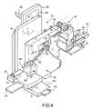
- FIG. 4is a perspective view of the immobilization, ultrasound imaging and biopsy assemblies of the embodiment of FIG. 1 .
- FIG. 5is a perspective view of an ultrasound imaging head employable in the present invention.
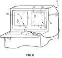
- FIG. 6illustrates spatially correlated x-ray and ultrasound images of a potential breast lesion/suspicious mass obtainable with the present invention.
- FIG. 7illustrates a side-view of an alternative embodiment of an ultrasound imaging assembly comprising the present invention.
- FIG. 8illustrates a partially cut-away end view of the alternate ultrasound imaging assembly embodiment of FIG. 7 .
- FIG. 9Ais a schematic diagram of a linear ultrasound probe head array in accordance with the present invention.
- FIG. 9Bis a schematic diagram illustrating an ultrasound signal profile for the probe of FIG. 9A .
- FIG. 9Cis a schematic diagram of a planar ultrasound probe head array in accordance with the present invention.
- FIG. 9Dis a schematic diagram showing an ultrasound signal profile for the probe head of FIG. 9C .
- FIGS. 10-20show various screens of a user interface system in accordance with the present invention.
- FIGS. 1-6illustrate one embodiment of a diagnostic ultrasound/x-ray biopsy system comprising the present invention, as adapted for mammography/breast biopsy use.
- the systemcomprises a support assembly 10 having a patient table 12 with breast-opening 14 therethrough, an immobilization assembly 30 for immobilizing a patient's breast within a predetermined XYZ frame of reference under the opening 14 of table 12 , an x-ray imaging assembly 40 for providing two-dimensional x-ray images (e.g., X-Y images) of the patient's immobilized breast in correlated spatial relation to the predetermined XYZ frame of reference, and an ultrasound imaging assembly 100 for providing orthogonal depth-profile images (e.g., X-Z, Y-Z and/or X, Y-Z images) of the immobilized breast in correlated spatial relation to the predetermined XYZ frame of reference.
- an immobilization assembly 30for immobilizing a patient's breast within a predetermined XYZ frame of reference under the opening 14 of table 12
- an x-ray imaging assembly 40for providing two-dimensional x-ray images (e.g., X-Y images) of the patient'
- a biopsy assembly 50 having puncture instrument 52is also provided for obtaining samples from a patient's breast while the breast is immobilized in the predetermined XYZ frame of reference.
- a display/processor assembly 60is provided for recording/displaying the various images obtained/generated, for determining the coordinates of a user-identified location of interest within the breast and for monitoring/controlling/simulating the position of the various positionable assembly components.
- the illustrated embodimentmay utilize the x-ray, automated biopsy and other functionalities embodied in the current MAMMOTEST® and MAMMOVISION® products of Fischer Imaging Corp. of Denver, Colo., U.S.A.
- the present inventionallows for the integration and effective use of ultrasound imaging with such products, thereby allowing medical equipment cost efficiencies to be realized.
- the MAMMOTEST® and MAMMOVISION® productsinclude features corresponding with the disclosures in U.S. Pat. Nos. 5,078,142, 5,240,011 and 5,415,169, and 5,735,264, which are incorporated by reference in their entirety.
- Support assembly 10further includes pedestal 16 and cantilevered first and second support arms 20 and 22 , respectively, for supportably interfacing the breast immobilization assembly 30 , x-ray imaging assembly 40 , ultrasound imaging assembly 100 and biopsy assembly 50 in a predetermined spatially correlated manner.
- First and second supports arms 20 and 22can be jointly pivoted relative to pedestal 16 , thereby providing imaging/biopsy access to the breast from different directions (e.g., 0°, +90° and ⁇ 90° relative to the table longitudinal axis).
- second support arm 22can be selectively pivoted relative to first support arm 20 , to provide for stereotactic x-ray imaging (e.g., +15° and ⁇ 15° relative to the first support arm longitudinal axis).
- Breast immobilization assembly 30is supported on first support arm 20 and includes a stationary face plate 32 and opposing compression paddle 34 for immobilizing a patient's breast therebetween.
- Compression paddle 34is x-ray transmittent and further includes a window 36 for direct breast access by the ultrasound imaging assembly 100 and/or biopsy assembly 50 .
- Compression paddle 34is selectively positionable along first support arm 20 (e.g., via motorized and position sensor systems) for controlled, registered movement toward/away from face plate 32 to accommodate breast positioning/removal and differing breast sizes.
- Compression paddle 34can be readily removed from/interconnected to the first support arm 20 to accommodate the selective use of compression paddles of differing sizes, shapes, window positions, etc. As shown in FIG.
- compression assembly 30may further include selectively advanceable/retractable auxiliary side paddles 38 , each having optional openings for breast access (e.g., by a puncture instrument or an ultrasound imaging head) for further compression/breast immobilization within the predetermined XYZ frame of reference, and particularly during use of biopsy assembly 50 .
- compression paddle 34 and face plate 32are intended to define a breast imaging area of substantially common thickness and to immobilize such area during imaging/biopsy procedures, and to otherwise provide direct access to the breast for targeted ultrasound imaging/biopsy procedures.
- X-ray imaging assembly 40includes x-ray tube source 42 mounted on the end of second support arm 22 and x-ray receiver/imager 44 mounted on first support arm 20 .
- x-ray tube source 42provides x-ray radiation having a center axis C substantially perpendicular to the fronts of face plate 34 and x-ray receiver/imager 44 , such x-ray radiation having a focal point positioned along the center axis C at a determinable location between the face plate 32 and compression paddle 34 during use.
- the predetermined XYZ frame of referencecan be defined in the illustrated embodiment in relation to an X-Y plane corresponding with the front surface of the face plate 32 and/or parallel back surface of compression paddle 34 , together with orthogonal X-Z and Y-Z planes within which the x-ray radiation center axis passes (i.e., all three planes being orthogonal).
- X-ray opaque markingscan be provided on compression paddle 34 and/or face plate 32 to facilitate spatial correlation of the radiation center axes and x-ray receiver/imager.
- the x-ray receiver/imager 44is disposed in abutting relation with the face plate 32 .
- X-ray receiver/imager 44may comprise an image receptor consisting of a removable radiographic film cassette (e.g., for full-field breast imaging) and/or digital camera (e.g., for partial field, real-time imaging/display).
- a partial field, digital CCD camera 46e.g., having a 5 mm ⁇ 10 mm or 5 mm ⁇ 5 mm imaging area
- ultrasound imaging assembly 100 and biopsy assembly 50are selectively and alternatively connectable to opposing sides of first support arm 20 via connection/locking handles 102 and 55 , respectively. Additionally, biopsy assembly 50 may be mounted in an axially aligned manner on first support arm 20 for breast access through window 36 .
- a reference, or “home,” position for each assembly in a given mounted locationis known relative to the predetermine XYZ frame of reference. Further, positioning of the various components of each assembly during use is automatically determinable via position sensor/control systems. As will be appreciated, such positioning can be automated via corresponding processor-controlled, servo motors.
- Biopsy assembly 50comprises a punction sub-assembly 54 , which includes puncture instrument 52 , and positioner sub-assembly 56 .
- Positioner sub-assembly 56includes horizontal axis and vertical control motors 58 and 60 , respectively, for selective sideward movement and upward angulation of the punction instrument 52 .
- punction sub-assembly 56may comprise the AUTOGUIDETM assembly of Fischer Imaging Corporation.
- the illustrated embodimentmay be particularly apt for use with punction subassemblies for obtaining samples having relatively large cross-sections, including, for example, the MAMMOTOMETM from Biopsys Medical, Inc. of Irvine, Calif.
- Ultrasound imaging assembly 100comprises an ultrasound imaging head, or probe, 110 interconnected to arm assembly 130 and, in turn, to XYZ ultrasound positioning assembly 140 .
- XYZ ultrasound positioning assembly 140is employed to selectively position ultrasound imaging head 110 through the window 36 of compression paddle 34 to establish direct breast contact for targeted ultrasound imaging in determinable spatial relation to the predetermined XYZ frame of reference.
- ultrasound probe 110may include an elongated housing 112 with an elongated ultrasound transducer module 114 positioned therein.
- Ultrasound transducer module 114provides an ultrasound signal having a focal point on a signal center axis at a location between compression paddle 34 and face plate 32 .
- Ultrasound transducer module 114may include, for example, a phased linear array of ultrasound transducers positioned along a longitudinal axis of the ultrasound probe 110 .
- the ultrasound probe 110emits signal pulses and detects corresponding echo pulses to generate the depth-profile images.
- detected echo pulseswill result from ultrasound transmissivity differences (i.e., ultrasound impedance mismatches) at tissue-type transition areas (e.g., transitions between healthy tissue and a potential lesion/suspicious mass) and at structural obstructions (e.g., the front surface of face plate 32 ).
- the housing 112 of ultrasound probe 110may include a recess 118 (exaggerated in FIG. 5 ) for receiving a cold-pack 120 for orthogonal application to a biopsy site after a biopsy procedure. Applying pressure and a cold medium directly over a biopsy site in the breast has been shown to reduce hematoma bleeding and bruising.
- XYZ ultrasound positioning assembly 140includes X, Y and Z platforms 142 , 146 and 148 , respectively, mounted for selective, registered movement on corresponding support members 152 , 156 and 158 relative to the predetermined XYZ frame of reference.
- XYZ positioning assembly 140may include internal X, Y and Z optical position encoders.
- XYZ positioning assembly 140can further include X, Y and Z motor drives for automatic, selective positioning of ultrasound imaging head 110 in registered XYZ relation to the predetermined XYZ frame of reference.
- the XYZ positioning assembly 140may also include counterbalance and electro-lock components to accommodate ready manual positioning and to maintain a selected ultrasound imaging/biopsy position, respectively.
- Arm assembly 130is provided to allow the ultrasound imaging probe 110 to be rotated about one or more of selected X, Y and Z axes to obtain a desired pitch, roll and/or yaw orientation).
- arm assembly 130can be controlled to selectively rotate the longitudinal axis, or pitch, of probe 110 so that the ultrasound signal may be employed to obtain depth-profile image in a plane, or “slice,” within which an upwardly angled punction instrument 52 of biopsy assembly 50 may be orthogonally advanced, as will be further discussed.
- arm assembly 130includes pivot arm 132 pivotally interconnected to XYZ ultrasound positioning assembly 140 via a lock/release mechanism (not shown) for selective, centered rotation of probe 116 about axis YY.
- Arm assembly 130further includes arm 134 rotatably interconnected to arm 132 via a lock/release mechanism (not shown) for selective, centered rotation of probe 116 about axis XX, and arm 136 rotatably interconnected to arm 134 via a lock/release mechanism (not shown) for selective, centered rotation of probe 116 about axis ZZ.
- Internal optical encodersmay be provided at the various arm interconnections, wherein the pitch, roll and/or yaw of probe 110 is automatically determinable in relation to the predetermined XYZ frame of reference. In this regard, internal automated micro-positioners may also be utilized under processor control.
- the ultrasound signalmay be scanned to obtain depth-profile information for a predetermined layer, or “slice,” within the region of interest.
- scanningmay be provided electrically by driving a phased linear array of transducers comprising probe 110 in a known manner and/or via manual or automatic-driven control of XYZ positioning assembly 140 to mechanically move ultrasound imaging head 110 .
- display/processor 60includes a display screen 62 for displaying the acquired x-ray images on a first portion 62 a and displaying corresponding depth-profile ultrasound images on a second portion 62 b , each in registered co-relation to the predetermined XYZ frame of reference.
- Display/processor 60may further include a user interface means 64 , e.g., keyboard 65 and mouse 66 and screen point cursor 68 (e.g., on both display portions 62 a , 62 b ), wherein a user may identify (e.g., click upon) a specific location-of-interest within both an x-ray image and corresponding ultrasound image (e.g., corresponding with a potential lesion or suspicious mass), e.g., for automatic processor determination of the three-dimensional coordinates of the location within the predetermined XYZ frame of reference.
- a user interface means 64e.g., keyboard 65 and mouse 66 and screen point cursor 68 (e.g., on both display portions 62 a , 62 b ), wherein a user may identify (e.g., click upon) a specific location-of-interest within both an x-ray image and corresponding ultrasound image (e.g., corresponding with a potential lesion or suspicious mass), e.g.,
- User interface meansmay further allow for user selection/display of a particular desired ultrasound depth-profile image, e.g., via mouse 66 and screen “slice” cursor 70 on the x-ray image display portion 62 a .
- screen “slice” cursor 70may be employed to identify a particular slice, or layer, of an X-Y x-ray image for which a corresponding ultrasound depth-profile image is to be obtained (e.g., thereby resulting in processor-assisted positioning and imaging using probe 110 ) and/or accessed and displayed (e.g., where such ultrasound depth-profile image has been previously obtained/stored for selective subsequent review).
- display/processor 60may be operatively interconnected (e.g., via electrical lines 80 ) to the various positionable assembly components for monitoring/controlling their respective positions relative to the predetermined XYZ frame of reference, including the positionable components of immobilization assembly 30 , x-ray imaging assembly 40 , ultrasound imaging assembly 110 and biopsy assembly 50 .
- display/processor 60may determine the three-dimensional coordinates of a specific location of interest, as described above, and in turn assist/control the positioning of biopsy assembly 50 so as to position the assembly for obtainment of a tissue sample from the location of interest.
- the display/processor 60may also be employable to visually project, or simulate, the entry of a punction instrument 52 into a given location of interest, thereby allowing physicians the opportunity to insure an optimal positioning for biopsy entry prior to an actual biopsy procedure. Since three-dimensional visualization of a potential lesion/suspicious mass can be provided by the present invention, and since the disclosed arrangement allows for breast access by biopsy assembly 50 from a plurality of aspects (e.g., by selective mounting on either side of or coaxial along support arm 20 ), such simulated biopsy modeling may prove to be of particular advantage.
- the present inventionallows for spatial correlation of the x-ray and ultrasound images utilizing various techniques.
- the X-Y x-ray images obtainedcan be readily correlated to the predetermined XYZ frame of reference since the position and attributes of x-ray source 42 and x-ray receiver/imager 44 are each known in relation to the predetermined XYZ frame of reference.
- the two X-Y stereotactic x-ray imagescan be employed to obtain a Z location for particular location of interest relative to the predetermined XYZ frame of reference utilizing known triangulation techniques, as will be appreciated by those skilled in the art.
- the XYZ positioning of ultrasound imaging head 110is determinable relative to the predetermined XYZ frame of reference, as noted above.
- the ultrasound imaging head 110will emit/detect ultrasound signals in substantially the same plane as the surface of compression paddle 34 contacting the imaged breast.
- the position of such surface relative to the predetermined XYZ frame of referencee.g., the Z distance to face plate 32 .
- a patientcan be positioned on the table 12 with a breast positioned through opening 14 .
- Compression paddle 34is then advanced along first support arm 20 to compress the breast to define a cross-sectional imaging area having a common thickness and to otherwise immobilize the breast in a set position within the predetermined XYZ frame of reference.
- X-ray imaging assembly 40is then selectively positioned to obtain the desired x-ray images. Such x-ray images are then reviewed using display/processor 60 , to identify, analyze and or otherwise confirm the presence and location of a potential lesion or suspicious mass for ultrasound imaging. Alternatively, the general location of a potential lesion or suspicious mass may already be known due to prior x-ray screening.
- the patientshould be positioned/repositioned so that the potential lesion or suspicious mass is positioned within the accessible field of view of ultrasound imaging head 110 when it is maneuvered through the window 36 of compression paddle 34 in direct contact with the imaged breast.
- new x-ray and corresponding ultrasound imagesshould be generated for each position in which a breast is immobilized within the predetermined XYZ frame of reference.
- ultrasound imaging probe 110is positioned through the window 36 and a series of ultrasound images are obtained and displayed on display/processor 60 .
- Cursor 66 control of the ultrasound images taken across the area of interestprovides additional, valuable information as to the type of potential lesion/suspicious mass originally noted on an original mammogram. For example, with proper training of ultrasound and x-ray imaging techniques, physicians may rule out the possibility of a solid mass in favor of a fluid-filled cyst. Or, additional ultrasound characteristics may aid the physician in making a definitive diagnosis.
- the specific location from which tissue is to be obtainedcan be identified using mouse 66 to position screen point cursor 68 on both the x-ray image and correlated ultrasound depth-profile image on display/processor 60 . Three-dimensional coordinates can then be determined and utilized by display/processor 60 to control positioning of biopsy assembly 50 .
- specific attributes of the particular punction subassembly 54 utilizedwill have been previously entered into by display/processor 60 .
- display/processor 60may be employed to simulate the advancement of punction instrument 52 into the breast from a given potential position, thereby allowing the physician to determine if breast biopsy access from a different position may be more desirable.
- the ultrasound imaging head 110may be utilized to provide continuous, successive depth profile images, thereby allowing for real-time monitoring and user control of the advancement of the punction instrument 52 into the breast. More particularly, when the punction instrument is positioned at an angle ⁇ as illustrated in FIG. 2 , ultrasound imaging head 110 may be similarly angled at ⁇ (e.g., relative to horizontal) so as to yield real-time ultrasound depth-profile images of the layer into which punction instrument 52 is advanced. After biopsy procedures are completed, ultrasound imaging head 110 may be repositioned so as to allow for pressure application of a cold pack 120 .
- an ultrasound display systemis generally identified by the reference numeral 300 .
- an ultrasound display systemIn order to facilitate certain procedures such as a sampling of a suspicious lesion or tissue harvesting (or other targeted procedures such as guide wire placement, laser ablation or treatment delivery), it is desirable to provide an ultrasound display system in proximity to the patient's compressed breast.
- the availability of a substantially real time ultrasound displayis desirable to monitor the actual penetration path of a biopsy needle or other instrument into the patient's breast, for example, to verify that the instrument traverses the desired tissue and properly targets the area of interest.
- certain instrumentssuch as biopsy needles may have a tendency to deflect, particularly if the instrument contacts calcifications or other dense tissue structure.
- an ultrasound display system in proximity to the patient's breastallows the physician to verify that the instrument is properly targeting the area of interest and has not strayed due to deflection or otherwise. Moreover, the physician may wish to verify that a breast lesion has been sampled after activation of the biopsy instrument. Again, the availability of the ultrasound display system in proximity to the patient's breast facilitates such monitoring of a sampling process and sample verification.
- such monitoringis facilitated by providing an ultrasound display system 300 in proximity to the patient's breast under the table 12 .
- the system 300may be mounted to the table 12 , the pedestal 16 or another part of the support assembly 10 , or may be otherwise positionable in proximity to the patient's breast beneath the table 12 .
- the illustrated embodimentallows for sampling from various positions, including from either side of the patient's breast.
- the illustrated systemincludes a support and positioning assembly 306 . More specifically, the system includes a monitor 302 having a screen 304 for displaying ultrasound images.
- the illustrated assembly 306allows for a three-dimensional translation of the monitor 302 as well as angular orientation of the screen 304 for easy viewing by a physician during such a medical procedure.
- the various types of motion that are accommodated by the assembly 306are generally indicated by arrows in FIG. 3 .
- the support and positioning assembly 306includes an articulated positioning system including an upper arm 308 and a lower arm 314 .
- the upper armis interconnected to the table 12 by way of a swivel mechanism 310 and an upper pin 312 .
- the swivel mechanism 310allows the assembly 306 to rotate relative to the Y axis as indicated in FIG. 3 .
- the upper armcan pivot about upper pin 312 .
- the upper arm 308 and lower arm 314are interconnected in a manner that allows for relative swiveling and pivoting motion therebetween.
- a central pivoting mechanism 316allows for pivotal motion between the arms 308 and 314 .
- the lower arm 314is also rotatable about pin 318 so as to allow for relative swiveling motion between arm 314 and arm 308 .
- the lower arm 314in turn is interconnected to the monitor 302 in a manner that allows for swiveling and pivoting motion therebetween.
- lower pivoting mechanism 320allows for pivotal motion between 314 and monitor 302 .
- the monitor 302can swivel relative to the arm 314 by rotating about lower pin 324 .
- the lower pivoting mechanism 320allows for rotation about the post 322 .
- the assembly 306allows for three-dimensional translation of the monitor to a position as desired by the physician/user, and also allows for positioning of the screen 304 in a desired angular orientation relative to both vertical and horizontal planes. It will be appreciated that other types of positioning mechanisms including slides, telescoping arms, and linear drive mechanisms can be used to provide some or all of the illustrated motions, and such motions may be actuated manually or driven by motors.
- FIGS. 9A-9Dshow different ultrasound probe head configurations that may used to achieve different ultrasound signal characteristics in accordance with present invention.
- the illustrated head 900is a linear head including a linear array of conventional ultrasound probe elements 902 .
- Each such elementincludes an ultrasound transducer operative for both transmitting ultrasound signals to the patient and receiving echo signals returning from the patient.
- the ultrasound elementsmay include a piezo transducer that is operative to transmit ultrasound signals by flexing or otherwise displacing in response to input electrical signals.
- the return signalscause the transducer element to flex or otherwise displace thus creating an electrical output representative of the received return ultrasound signal.
- the wave form of the output signalprovides information regarding the density of the tissue from which the signal was reflected.
- the transit timei.e., the elapsed time between signal transmission and signal detection, provides information regarding the distance or depth relative to the head of the tissue that reflected the signal.
- the ultrasound imageprovides information regarding the nature and location of tissue within the patient's breast.
- the illustrated head 900may include, for example, 128 elements arranged in a single row and may be driven by, for example, a 10 MHz signal.
- FIG. 9Bshows a top schematic view of the probe 900 .
- the probe headtransmits a focused ultrasonic signal 901 having a profile as generally illustrated.
- the signalincludes a focal area within which high quality images can be obtained.
- the depth of this focal regionis indicated by D 1 .
- the ultrasound imaging systemmay process the return signal over a corresponding time period.
- ultrasound probesare generally operated in a series of alternating transmit and receive time periods. During a first transmit time period, an ultrasound signal is transmitted into the patient. At the end of the transmit time period, the transmission signal is terminated and the probe remains available for receiving return signals. The time at which return signals are received depends on the depth of the tissue from which such signals are reflected.
- an image corresponding to the area indicated by D 1can be provided by processing the return signal over the corresponding time period.
- FIG. 9Cshows a front perspective view of a planar ultrasound probe head arrangement.
- the head 904includes ultrasound elements arranged in rows 908 and columns 906 .
- the forward surface of the front column 908is disposed approximate to the patient.
- the various columns 908are disposed at varying distances from the patient.
- FIG. 9Dshows a top schematic view of the head 904 of FIG. 9C .
- the elements in each of the columns 908transmit focused ultrasound signals 905 . Because the columns are disposed at different distances from the patient or at different locations relative to the signal axis, the signals transmitted from the elements of the various columns 908 define a focal region having a depth D 2 that is greater than the depth D 1 of the head 900 of FIGS. 9A and 9B .
- the illustrated head 900includes more than one column 908 and may include, for example, seven or more columns. Each column may include, for example, 128 elements 906 .
- the planar array configuration of head 904provides imaging advantages.
- the head 904provides such focal depth. Accordingly, for most patients, the head 904 can provide high quality images of an area of interest within the patient's breast regardless of the location of the area of interest relative to the thickness of the patient's compressed breast.
- the ultrasound imaging assembly 100may be initially used to obtain a scout image or image set.
- arm 136may be positioned so that the ultrasound head 116 is in a vertical orientation, i.e., substantially aligned with axis Y of FIG. 2 .
- the assembly 100can then be moved along the X axis of FIG. 2 so as to obtain ultrasound imaging exposures at various known locations along the X axis to thereby image the area of interest 46 , e.g., in the form of multiple ultrasound image slices.
- three-dimensional imaging informationis provided for the location of interest 46 This information can then be used to provide targeting coordinates for the biopsy assembly 50 .
- the arm 136can be rotated such that it is aligned with axis 52 of a medical instrument such as a biopsy needle or gun.
- the imaging assembly 100can be used to provide substantially real time imaging information for monitoring insertion of the biopsy needle and sampling of the location of interest 46 .
- FIGS. 7 and 8pertain to an alternate embodiment of an ultrasound imaging assembly 200 .
- the ultrasound imaging assembly 100 described hereinaboveis supportably positioned below and on one side of a center axis of patient table 12
- the alternate ultrasound imaging assembly 200is provided to be supportably positioned immediately below and in substantial coaxial alignment with patient table 12 .
- Such positioning of the ultrasound imaging assembly 200allows for the alternate positioning of a biopsy a assembly 50 , as described above, on either side below patient table 12 , thereby yielding enhanced access to the above-noted predetermined XYZ frame of reference.
- the ultrasound imaging assembly 200is supportably positioned on and in coaxial relation to the first support arm 20 .
- First support arm 20also carries breast immobilization assembly 30 .
- the breast immobilization assembly 30includes a stationary face plate 32 and opposing compression paddle 34 for immobilizing a patient's breast therebetween.
- Compression paddle 34again is x-ray transmittent and includes a window 36 for direct breast access therethrough by the ultrasound imaging assembly 200 and/or a biopsy assembly 50 .
- Compression paddle 34is selectively positionable along the first support arm 20 .
- a locking mechanism portion 38 of compression paddle 34is sized in the embodiment of FIG. 7 for positioning under at least a portion of ultrasound imaging assembly 200 to yield overall enhanced access and compactness advantages.
- Support arm 20may also support an x-ray image receiver/imager 244 positioned in opposing relation to the x-ray tube source 42 .
- Image receiver/imager 244may comprise a removable radiographic film cassette and/or digital CCD camera assembly for partial or full-field, real time imaging.
- receiver/imager 244may comprise a CCD assembly for full-field imaging as described in U.S. Pat. No. 5,526,394, hereby incorporated by reference.
- the assemblyincludes an ultrasound imaging probe 210 having an imaging head 212 (e.g., comprising an ultrasound transducer and/or linear array of transducers) positioned at the end of an elongated handle portion 214 .
- the handle portion 214is configured for selective grasping during hand-held use and alternatively for positioning within a holder 220 having a cradle-like configuration.
- the holder 220includes two interconnected and aligned u-shaped portions for conformally receiving a cylindrically shaped probe handle 214 (e.g., via “snap-in” and/or slide-in engagement).
- probe handle 214 and holder 220may include projections and receiving slots or other means for establishing a predetermined positional relationship therebetween when engaged.
- the probe 210may include an interconnect line 218 for transferring image data to a display/processor 60 .
- holder 220is mounted to an XYZ positioning assembly 240 .
- the XYZ ultrasound positioning assembly 240includes X, Y and Z platforms 242 , 246 and 248 , respectively, mounted for selective, registered movement on corresponding support members 252 , 256 and 258 relative to the predetermined XYZ frame of reference (i.e., defined between compression paddle 34 and face plate 32 ).
- the entire assembly 200may be selectively removed from/interconnected to the support arm 20 utilizing a carrier assembly 260 having a depressible hand grasp 262 for retracting/advancing a locking pin(s) that interfaces with one or more openings along support arm 220 .
- Ultrasound imaging assembly 200further comprises a first motor assembly 270 for driving X platform 242 for automated side-to-side movement of probe 210 in the X dimension.
- ultrasound imaging assembly 200also comprises a second motor assembly 280 for automated driving of platform 246 for up/down positioning of probe 210 in the Y dimension. Positioning in the Z dimension may be established by moving platform 248 relative to support member 258 .
- Ultrasound imaging assembly 200also includes a third motor assembly 290 for rotational movement of the holder 220 , and in turn probe 210 mounted therewithin, about the axis ZZ.
- holder 220includes a microencoder for establishing the particular desired rotational angle of the ultrasound imaging probe head 212 (i.e., and the transducer and/or transducer array thereof) relative to the ZZ axis within the XY plane defined by the face 214 of the probe 210 .
- FIGS. 10-20illustrate screens of a user interface system that may be employed in connection with the embodiments described above for procedures including localization, targeting and sampling of an area of interest in a patient's breast.
- an initial screen of the user interface systemis shown.
- the screenmay be displayed on a conventional display system such as an LCD or CRT computer monitor.
- the screensmay be displayed on the display/processor assembly 60 of FIGS. 1-6 .
- the initial screenincludes an image display area 1000 and a user input area 1002 .
- the user input area 1002includes a number of graphical objects or buttons corresponding to particular functions such that the functions can be assessed and/or implemented by activating a cursor relative to the graphical objects, touching the graphical objects or other inputs relative to the objects. As shown in FIG. 10 ,
- the objectsinclude a button 1004 labeled “Mammotest”, a button 1006 labeled HF-X, a button 1008 labeled “Ultrasound”, a button 1010 labeled “Help”, a button 1012 labeled “U/S Image Procedure”, a button 1014 labeled “Utilities” and a button 1016 labeled “HF-X Only Utilities”. These buttons allow the user to select as between various operating modes of the system.
- the systemmay be used for conventional upright x-ray procedures corresponding to the button HF-X, prone stereotactic imaging applications corresponding to the button labeled “Mammotest” or, of particular relevance with respect to the present discussion, for ultrasound-based procedures corresponding to the buttons 1008 and 1012 .
- the Help button 1010can be used to access a variety of instructional information and operating information for the system.
- the Utilities button 1014can be used to access various utilities screens, for example, relating to accessing records, changing display parameters such as brightness, etc.
- the HF-X Only Utilities button 1016provides access to utility information relating to the HF-X mode of operation.
- the usermay activate ultrasound button 1008 in order to initiate ultrasound related procedure.
- FIG. 11illustrates a subsequent screen of the user interface system.
- the screenincludes a display area 1102 , a user input area 1104 and an instruction area 1106 .
- the instruction area 1106provides instructions to the user with regard to the current screen.
- the illustrated screenincludes instructions directing the user to enter patient data and to click “Done” when finished.
- the usermay then enter a patient name, patient identification number, a physician name, a date of procedure, a technician's initials and any other information as desired into the display area 1102 .
- Such informationis used, for example, for purposes of maintaining records and facilitating later retrieval of desired images.
- the user input areaincludes graphical objects 1108 , 1110 and 1112 respectively labeled “Lateral Approach”, “Target on Scout”, and print DB Entry.
- the Print button 1112can be used to provide a hard copy of the screen including, for example, the entered patient information.
- the lateral approach button 1108allows the user to indicate when a lateral approach is being utilized for imaging the patient's breast.
- the Target on Scout 1110allows the user to indicate that a scout image is to be obtained. For example, an x-ray scout image may initially be displayed to identify the area of interest for use in positioning the targeted ultrasound system. It will thus be appreciated that the sequence of screens presented to the user may vary depending on the specific procedure to be implemented as indicated through appropriate entries relative to the displayed graphical objects.
- FIG. 12illustrates a screen which may be presented in the case where the user desires to obtain an initial scout image.
- the display area 1202is blank pending acquisition of the scout image.
- the instructions in area 1204indicate that the system is ready for acquiring the scout image and provides information regarding positioning of the x-ray tube. Specifically, the instructions indicate that the x-ray tube should be positioned to 0 degrees corresponding to a top to bottom imaging angle relative to the patient's breast. It is also possible for the user to skip the digital scout image by selecting the skip digital scout button 1208 in input area 1206 . For acquisition of the scout image, the ultrasound imaging system may be removed to avoid interference.
- the three-dimensional coordinates of a location of interest within the patient's breastcan be identified based on a digital x-ray image and an ultrasound image.
- a digital x-ray imageis displayed in the display area 1302 . This x-ray image can be used to identify the location of interest relative to the two dimensional image so as to allow for appropriate positioning of the ultrasound imaging system.
- buttonsinclude: a reverse video button for reversing the tone of the displayed x-ray image, i.e., to provide a negative of the displayed image; a squeeze button for minimizing the display area occupied by the image; a contrast button for varying the contrast of the image; a ruler button for providing a scale for dimensional reference with respect to the image; a fall resolution button for displaying the image with maximum resolution; an edge enhancement button for identifying and enhancing the edges of displayed structural features for enhanced structure identification; an autocontrast button for automatically fixing the contrast level; a zoom button for zooming in on a particular area of the image, for example, as identified by a cursor input; a KV button for activating a kilovolt sensor to control the power of an exposure; and an exposure control button for allowing the user to manually control exposure.
- FIGS. 14 and 15illustrate a process for positioning an ultrasound probe.
- the x-ray imageis used in conjunction with an ultrasound image to localize an area of interest in three dimensions in the following manner.
- the x-ray imageis display in the display area as shown at 1402 in FIG. 14 .
- a line within the image in the display area 1402indicates a current position of the ultrasound probe.
- an arrowheadis provided at one end of the line to indicate a rearward end of the ultrasound probe.
- the usercan position the ultrasound probe by clicking on the location of interest in the x-ray image.
- the motors associated with the ultrasound positionerwill drive the ultrasound probe to the desired location relative to the two dimensions of the x-ray image.
- the ultrasound probeautomatically moves to the indicated point on the x-ray scout image. It will thus be appreciated that two dimensional coordinates of the location of interest are encoded into the position of the ultrasound transducer.
- the ultrasound imaging systemcan then be used to identify the third dimension, or depth, of the location of interest.
- the ultrasound image systemis activated to provide a second image which is displayed in the display area 1502 as shown in FIG. 15 .
- the userfirst selects the mark lesion button in user input area 1504 and then positions and activates the cursor over the location of interest on the ultrasound image, per the instructions in area 1506 . This process is illustrated in FIG. 16 .
- FIGS. 15 and 16also include a select needle button in the user input area. It will be appreciated that different biopsy needles have different dimensions which need to be accounted for in targeting the location of interest for sampling. Such information can be entered by using the select needle button.
- FIG. 17shows the results of a three dimensional localization procedure.
- the target coordinates together with certain other patient and procedural informationare displayed in display area 1702 .
- the information displayed in this regardmay include three-dimensional coordinate information as well as adjusted coordinate information to account for certain offsets relating, for example, to the geometry of the needle holder and needle.
- Also shown in the ultrasound image in the display area 1702is a projected needle path for the sampling procedure.
- an indicationmay be provided in the display area 1702 or otherwise regarding the angular orientation of the displayed images.
- the illustrated display area 1702includes an indication that the ultrasound positioner is rotated to a position identified as 43 degrees.
- FIGS. 18-20illustrate a subsequent needle biopsy procedure.
- the ultrasound probemay be aligned relative to the penetration axis of the biopsy needle such that penetration of the biopsy needle can be viewed in real time.
- This video informationwhich is also displayed on the under table monitor, is shown in FIGS. 18-20 .
- FIG. 18shown an initial penetration of the biopsy needle towards the location of interest.
- An indicated of the penetration pathis overlaid in the image relative to the biopsy needle.
- the biopsy needlemay deflect from its intended course, for example, due to contact with calcifications or other dense structure within the patients breast. For this reason, the availability of real time ultrasound imaging during this process is an important advantage of the illustrated system.
- the usercan manually correct the positioning of the biopsy needle.
- the instructions in area 1804remind the user to consider correcting the course by using raised needle and lower needle buttons provided in conjunction with the ultrasound probe positioner.
- the illustrated systemcan be programmed to identify any diversion between the actual penetration path and the projected penetration path so as to issue an alert or allow for automatic correction.
- FIG. 19shows a position of the biopsy needle prior to activation of the needle to harvest tissue or cells from the area of interest.
- typical biopsy needle gunsare operated by positioning the biopsy needle a short distance from the location of interest and pointed towards the location of interest and then activating the gun so that the needle is thrown a distance through the area of interest such as under spring force.
- FIG. 19shows the pre-fire position of the biopsy needle and
- FIG. 20shows the post-fire position of the biopsy needle.
Landscapes
- Health & Medical Sciences (AREA)
- Life Sciences & Earth Sciences (AREA)
- Engineering & Computer Science (AREA)
- Medical Informatics (AREA)
- Surgery (AREA)
- Public Health (AREA)
- Radiology & Medical Imaging (AREA)
- Nuclear Medicine, Radiotherapy & Molecular Imaging (AREA)
- Biomedical Technology (AREA)
- Heart & Thoracic Surgery (AREA)
- Biophysics (AREA)
- Molecular Biology (AREA)
- Physics & Mathematics (AREA)
- Animal Behavior & Ethology (AREA)
- General Health & Medical Sciences (AREA)
- Pathology (AREA)
- Veterinary Medicine (AREA)
- High Energy & Nuclear Physics (AREA)
- Optics & Photonics (AREA)
- Human Computer Interaction (AREA)
- Computer Vision & Pattern Recognition (AREA)
- Dentistry (AREA)
- Oral & Maxillofacial Surgery (AREA)
- Apparatus For Radiation Diagnosis (AREA)
- Ultra Sonic Daignosis Equipment (AREA)
Abstract
Description
Claims (19)
Priority Applications (2)
| Application Number | Priority Date | Filing Date | Title |
|---|---|---|---|
| US10/260,719US7496398B2 (en) | 1996-10-15 | 2002-09-27 | Spatially correlated x-ray and ultrasound mammographic imaging systems and method |
| US12/365,918US20090143674A1 (en) | 1996-10-15 | 2009-02-05 | User interface system for mammographic imager |
Applications Claiming Priority (5)
| Application Number | Priority Date | Filing Date | Title |
|---|---|---|---|
| US08/730,107US5776062A (en) | 1996-10-15 | 1996-10-15 | Enhanced breast imaging/biopsy system employing targeted ultrasound |
| US09/111,094US6102866A (en) | 1996-10-15 | 1998-07-06 | Enhanced breast imaging/biopsy system employing targeted ultrasound |
| US10988198P | 1998-11-25 | 1998-11-25 | |
| US09/449,267US6459925B1 (en) | 1998-11-25 | 1999-11-24 | User interface system for mammographic imager |
| US10/260,719US7496398B2 (en) | 1996-10-15 | 2002-09-27 | Spatially correlated x-ray and ultrasound mammographic imaging systems and method |
Related Parent Applications (2)
| Application Number | Title | Priority Date | Filing Date |
|---|---|---|---|
| US09/111,094DivisionUS6102866A (en) | 1996-10-15 | 1998-07-06 | Enhanced breast imaging/biopsy system employing targeted ultrasound |
| US09/449,267DivisionUS6459925B1 (en) | 1996-10-15 | 1999-11-24 | User interface system for mammographic imager |
Related Child Applications (1)
| Application Number | Title | Priority Date | Filing Date |
|---|---|---|---|
| US12/365,918ContinuationUS20090143674A1 (en) | 1996-10-15 | 2009-02-05 | User interface system for mammographic imager |
Publications (2)
| Publication Number | Publication Date |
|---|---|
| US20030073895A1 US20030073895A1 (en) | 2003-04-17 |
| US7496398B2true US7496398B2 (en) | 2009-02-24 |
Family
ID=22330068
Family Applications (2)
| Application Number | Title | Priority Date | Filing Date |
|---|---|---|---|
| US09/449,267Expired - LifetimeUS6459925B1 (en) | 1996-10-15 | 1999-11-24 | User interface system for mammographic imager |
| US10/260,719Expired - Fee RelatedUS7496398B2 (en) | 1996-10-15 | 2002-09-27 | Spatially correlated x-ray and ultrasound mammographic imaging systems and method |
Family Applications Before (1)
| Application Number | Title | Priority Date | Filing Date |
|---|---|---|---|
| US09/449,267Expired - LifetimeUS6459925B1 (en) | 1996-10-15 | 1999-11-24 | User interface system for mammographic imager |
Country Status (4)
| Country | Link |
|---|---|
| US (2) | US6459925B1 (en) |
| EP (1) | EP1143845A4 (en) |
| AU (1) | AU2706500A (en) |
| WO (1) | WO2000051484A2 (en) |
Cited By (24)
| Publication number | Priority date | Publication date | Assignee | Title |
|---|---|---|---|---|
| US20060149162A1 (en)* | 2004-11-29 | 2006-07-06 | Derek Daw | Graphical user interface for tissue biopsy system |
| US20060251301A1 (en)* | 2004-11-02 | 2006-11-09 | Mcnamara Michael P Jr | Method and apparatus for determining correlation between spatial coordinates in breast |
| US20070217667A1 (en)* | 2003-12-19 | 2007-09-20 | Koninklijke Philips Electronics, N.V. | Image processing device for processing x-ray images |
| US20070237295A1 (en)* | 2006-01-25 | 2007-10-11 | Lutz Gundel | Tomography system and method for visualizing a tomographic display |
| US20080287827A1 (en)* | 2007-05-17 | 2008-11-20 | Vanderbilt University | System, method and device for positioning a target located within soft tissue in a path of an instrument |
| US20080298536A1 (en)* | 2007-06-03 | 2008-12-04 | Moshe Ein-Gal | Target positioner |
| US20090080594A1 (en)* | 2006-08-03 | 2009-03-26 | Kenneth Brooks | Dedicated breast radiation imaging/therapy system |
| US20090093715A1 (en)* | 2005-02-28 | 2009-04-09 | Donal Downey | System and Method for Performing a Biopsy of a Target Volume and a Computing Device for Planning the Same |
| US20090143674A1 (en)* | 1996-10-15 | 2009-06-04 | Nields Morgan W | User interface system for mammographic imager |
| WO2010102087A1 (en)* | 2009-03-06 | 2010-09-10 | Hologic, Inc. | Needle biopsy compression paddle system and method of use |
| US20100298705A1 (en)* | 2009-05-20 | 2010-11-25 | Laurent Pelissier | Freehand ultrasound imaging systems and methods for guiding fine elongate instruments |
| US20110116602A1 (en)* | 2009-11-17 | 2011-05-19 | Fujifilm Corporation | Image display apparatus and recording medium |
| US20110144544A1 (en)* | 2009-12-15 | 2011-06-16 | General Electric Company | Ultrasound transducer assembly and methods of using |
| US20120245463A1 (en)* | 2011-03-24 | 2012-09-27 | Thomas Mertelmeier | Tomosynthesis apparatus and method |
| US20150139518A1 (en)* | 2012-07-09 | 2015-05-21 | Kabushiki Kaisha Toshiba | Image processing apparatus |
| US9295449B2 (en) | 2012-01-23 | 2016-03-29 | Ultrasonix Medical Corporation | Landmarks for ultrasound imaging |
| KR20160091958A (en)* | 2013-11-29 | 2016-08-03 | 플란메드 오와이 | Mammography apparatus |
| US9636073B2 (en) | 2012-12-21 | 2017-05-02 | Caperay Medical (Pty) Ltd. | Dual-modality mammography |
| KR20170003503U (en)* | 2016-03-24 | 2017-10-12 | 에피소니카 코퍼레이션 | Breast ultrasound image capture device |
| US9950194B2 (en) | 2014-09-09 | 2018-04-24 | Mevion Medical Systems, Inc. | Patient positioning system |
| US10039527B2 (en) | 2009-05-20 | 2018-08-07 | Analogic Canada Corporation | Ultrasound systems incorporating spatial position sensors and associated methods |
| US10157491B2 (en) | 2012-12-28 | 2018-12-18 | Koninklijke Philips N.V. | Real-time scene-modeling combining 3D ultrasound and 2D X-ray imagery |
| US10314563B2 (en) | 2014-11-26 | 2019-06-11 | Devicor Medical Products, Inc. | Graphical user interface for biopsy device |
| US10835215B2 (en) | 2012-09-12 | 2020-11-17 | Convergent Life Sciences, Inc. | Method and apparatus for laser ablation under ultrasound guidance |
Families Citing this family (166)
| Publication number | Priority date | Publication date | Assignee | Title |
|---|---|---|---|---|
| US6731966B1 (en)* | 1997-03-04 | 2004-05-04 | Zachary S. Spigelman | Systems and methods for targeting a lesion |
| US6630937B2 (en)* | 1997-10-30 | 2003-10-07 | University Of South Florida | Workstation interface for use in digital mammography and associated methods |
| EP1143845A4 (en)* | 1998-11-25 | 2004-10-06 | Fischer Imaging Corp | User interface system for mammographic imager |
| US8036731B2 (en) | 2001-01-22 | 2011-10-11 | Spectrum Dynamics Llc | Ingestible pill for diagnosing a gastrointestinal tract |
| US8055329B2 (en) | 2001-01-22 | 2011-11-08 | Spectrum Dynamics Llc | Ingestible device for radioimaging of the gastrointestinal tract |
| US7826889B2 (en) | 2000-08-21 | 2010-11-02 | Spectrum Dynamics Llc | Radioactive emission detector equipped with a position tracking system and utilization thereof with medical systems and in medical procedures |
| US8489176B1 (en) | 2000-08-21 | 2013-07-16 | Spectrum Dynamics Llc | Radioactive emission detector equipped with a position tracking system and utilization thereof with medical systems and in medical procedures |
| US8565860B2 (en) | 2000-08-21 | 2013-10-22 | Biosensors International Group, Ltd. | Radioactive emission detector equipped with a position tracking system |
| US8909325B2 (en) | 2000-08-21 | 2014-12-09 | Biosensors International Group, Ltd. | Radioactive emission detector equipped with a position tracking system and utilization thereof with medical systems and in medical procedures |
| US6524246B1 (en)* | 2000-10-13 | 2003-02-25 | Sonocine, Inc. | Ultrasonic cellular tissue screening tool |
| JP2002158863A (en)* | 2000-11-22 | 2002-05-31 | Fuji Photo Film Co Ltd | Method and system for processing medical image |
| JP2002158862A (en)* | 2000-11-22 | 2002-05-31 | Fuji Photo Film Co Ltd | Method and system for processing medical image |
| US7597663B2 (en)* | 2000-11-24 | 2009-10-06 | U-Systems, Inc. | Adjunctive ultrasound processing and display for breast cancer screening |
| US7940966B2 (en)* | 2000-11-24 | 2011-05-10 | U-Systems, Inc. | Full-field breast image data processing and archiving |
| US7556602B2 (en)* | 2000-11-24 | 2009-07-07 | U-Systems, Inc. | Breast cancer screening with adjunctive ultrasound mammography |
| US7615008B2 (en)* | 2000-11-24 | 2009-11-10 | U-Systems, Inc. | Processing and displaying breast ultrasound information |
| US7103205B2 (en)* | 2000-11-24 | 2006-09-05 | U-Systems, Inc. | Breast cancer screening with ultrasound image overlays |
| US6757417B2 (en)* | 2000-12-27 | 2004-06-29 | Ge Medical Systems Global Technology Company, Llc | Method and apparatus for defining a three-dimensional imaging section |
| US20030149364A1 (en)* | 2002-02-01 | 2003-08-07 | Ajay Kapur | Methods, system and apparatus for digital imaging |
| FR2835731B1 (en)* | 2002-02-12 | 2004-10-22 | Ge Med Sys Global Tech Co Llc | MAMMOGRAPHY APPARATUS |
| US20030187349A1 (en)* | 2002-03-29 | 2003-10-02 | Olympus Optical Co., Ltd. | Sentinel lymph node detecting method |
| SE0201211D0 (en)* | 2002-04-23 | 2002-04-23 | Siemens Elema Ab | X-ray diagnostic apparatus for mammography examinations |
| US20030199753A1 (en)* | 2002-04-23 | 2003-10-23 | Ethicon Endo-Surgery | MRI compatible biopsy device with detachable probe |
| US7826883B2 (en)* | 2002-04-23 | 2010-11-02 | Devicor Medical Products, Inc. | Localization mechanism for an MRI compatible biopsy device |
| US20040082856A1 (en)* | 2002-07-16 | 2004-04-29 | Alfred E. Mann Institute For Biomedical Engineering, University Of Southern California | Support bra for ultrasonic breast scanner |
| FR2844985B1 (en)* | 2002-09-26 | 2004-12-10 | Ge Med Sys Global Tech Co Llc | MAMMOGRAPH WITH AUTOMATIC DETECTION OF COMPRESSION PELLET |
| US6825838B2 (en) | 2002-10-11 | 2004-11-30 | Sonocine, Inc. | 3D modeling system |
| US6928142B2 (en)* | 2002-10-18 | 2005-08-09 | Koninklijke Philips Electronics N.V. | Non-invasive plaque detection using combined nuclear medicine and x-ray system |
| EP1573495B1 (en)* | 2002-11-04 | 2009-11-04 | Spectrum Dynamics LLC | Apparatus and methods for imaging and attenuation correction |
| US7251353B2 (en)* | 2002-11-26 | 2007-07-31 | University Of Chicago | Automated method of patient recognition using chest radiographs |
| US10638994B2 (en) | 2002-11-27 | 2020-05-05 | Hologic, Inc. | X-ray mammography with tomosynthesis |
| US7616801B2 (en) | 2002-11-27 | 2009-11-10 | Hologic, Inc. | Image handling and display in x-ray mammography and tomosynthesis |
| US7577282B2 (en) | 2002-11-27 | 2009-08-18 | Hologic, Inc. | Image handling and display in X-ray mammography and tomosynthesis |
| US8571289B2 (en) | 2002-11-27 | 2013-10-29 | Hologic, Inc. | System and method for generating a 2D image from a tomosynthesis data set |
| US8565372B2 (en) | 2003-11-26 | 2013-10-22 | Hologic, Inc | System and method for low dose tomosynthesis |
| US7123684B2 (en) | 2002-11-27 | 2006-10-17 | Hologic, Inc. | Full field mammography with tissue exposure control, tomosynthesis, and dynamic field of view processing |
| JP4295283B2 (en)* | 2003-01-17 | 2009-07-15 | ヒー−ブーン パク | Ultrasonic inspection system for deformable objects |
| EP1475634B1 (en)* | 2003-04-25 | 2007-03-14 | BrainLAB AG | Method and apparatus for optimization of ultrasonic imaging |
| JP2004344480A (en)* | 2003-05-23 | 2004-12-09 | Fuji Photo Film Co Ltd | Image photographing device for mamma |
| US6846289B2 (en) | 2003-06-06 | 2005-01-25 | Fischer Imaging Corporation | Integrated x-ray and ultrasound medical imaging system |
| CN1981210A (en) | 2004-01-13 | 2007-06-13 | 光谱动力学有限责任公司 | Multi-dimensional image reconstruction |
| US8571881B2 (en) | 2004-11-09 | 2013-10-29 | Spectrum Dynamics, Llc | Radiopharmaceutical dispensing, administration, and imaging |
| WO2007054935A2 (en) | 2005-11-09 | 2007-05-18 | Spectrum Dynamics Llc | Dynamic spect camera |
| US7968851B2 (en) | 2004-01-13 | 2011-06-28 | Spectrum Dynamics Llc | Dynamic spect camera |
| WO2006051531A2 (en) | 2004-11-09 | 2006-05-18 | Spectrum Dynamics Llc | Radioimaging |
| WO2008010227A2 (en) | 2006-07-19 | 2008-01-24 | Spectrum Dynamics Llc | Imaging protocols |
| US8586932B2 (en) | 2004-11-09 | 2013-11-19 | Spectrum Dynamics Llc | System and method for radioactive emission measurement |
| US9470801B2 (en) | 2004-01-13 | 2016-10-18 | Spectrum Dynamics Llc | Gating with anatomically varying durations |
| CN1933787A (en)* | 2004-01-23 | 2007-03-21 | 特拉克斯医疗有限公司 | Methods and apparatus for performing procedures on target locations in the body |
| US8055324B1 (en)* | 2004-05-25 | 2011-11-08 | Sonultra Corporation | Rapid reports |
| EP1766550A2 (en) | 2004-06-01 | 2007-03-28 | Spectrum Dynamics LLC | Methods of view selection for radioactive emission measurements |
| EP1778957A4 (en) | 2004-06-01 | 2015-12-23 | Biosensors Int Group Ltd | OPTIMIZING THE MEASUREMENT OF RADIOACTIVE EMISSIONS IN SPECIFIC BODY STRUCTURES |
| US20050288581A1 (en)* | 2004-06-29 | 2005-12-29 | Ajay Kapur | Acoustic coupling gel for combined mammography and ultrasound image acquisition and methods thereof |
| US20060004283A1 (en)* | 2004-07-05 | 2006-01-05 | Naoto Moriyama | Medical image generating system and medical image generating method |
| US20080004526A1 (en)* | 2004-09-15 | 2008-01-03 | Scientific Biopsy Ltd. | Breast Cancer Detection and Biopsy |
| US20060074287A1 (en)* | 2004-09-30 | 2006-04-06 | General Electric Company | Systems, methods and apparatus for dual mammography image detection |
| US7662082B2 (en) | 2004-11-05 | 2010-02-16 | Theragenics Corporation | Expandable brachytherapy device |
| US9943274B2 (en) | 2004-11-09 | 2018-04-17 | Spectrum Dynamics Medical Limited | Radioimaging using low dose isotope |
| US8615405B2 (en) | 2004-11-09 | 2013-12-24 | Biosensors International Group, Ltd. | Imaging system customization using data from radiopharmaceutical-associated data carrier |
| US9316743B2 (en) | 2004-11-09 | 2016-04-19 | Biosensors International Group, Ltd. | System and method for radioactive emission measurement |
| US8423125B2 (en) | 2004-11-09 | 2013-04-16 | Spectrum Dynamics Llc | Radioimaging |
| US7702142B2 (en) | 2004-11-15 | 2010-04-20 | Hologic, Inc. | Matching geometry generation and display of mammograms and tomosynthesis images |
| WO2008059489A2 (en) | 2006-11-13 | 2008-05-22 | Spectrum Dynamics Llc | Radioimaging applications of and novel formulations of teboroxime |
| EP1816965B1 (en) | 2004-11-26 | 2016-06-29 | Hologic, Inc. | Integrated multi-mode mammography/tomosynthesis x-ray system |
| EP1844351A4 (en) | 2005-01-13 | 2017-07-05 | Biosensors International Group, Ltd. | Multi-dimensional image reconstruction and analysis for expert-system diagnosis |
| US8837793B2 (en) | 2005-07-19 | 2014-09-16 | Biosensors International Group, Ltd. | Reconstruction stabilizer and active vision |
| US8644910B2 (en) | 2005-07-19 | 2014-02-04 | Biosensors International Group, Ltd. | Imaging protocols |
| EP1908011B1 (en) | 2005-07-19 | 2013-09-04 | Spectrum Dynamics LLC | Reconstruction stabilizer and active vision |
| US7465268B2 (en) | 2005-11-18 | 2008-12-16 | Senorx, Inc. | Methods for asymmetrical irradiation of a body cavity |
| US8204500B2 (en) | 2005-12-28 | 2012-06-19 | Starhome Gmbh | Optimal voicemail deposit for roaming cellular telephony |
| WO2007095330A2 (en) | 2006-02-15 | 2007-08-23 | Hologic Inc | Breast biopsy and needle localization using tomosynthesis systems |
| US7557013B2 (en)* | 2006-04-10 | 2009-07-07 | Micron Technology, Inc. | Methods of forming a plurality of capacitors |
| US20070282221A1 (en)* | 2006-06-02 | 2007-12-06 | U-Systems, Inc. | Ultrasound assisted and x-ray assisted biopsy devices |
| US8894974B2 (en) | 2006-05-11 | 2014-11-25 | Spectrum Dynamics Llc | Radiopharmaceuticals for diagnosis and therapy |
| AU2007258679B2 (en)* | 2006-06-05 | 2013-02-21 | Senorx, Inc. | Biopsy system with integrated ultrasonic imaging |
| US7601966B2 (en)* | 2006-06-28 | 2009-10-13 | Spectrum Dynamics Llc | Imaging techniques for reducing blind spots |
| US20080086059A1 (en)* | 2006-10-04 | 2008-04-10 | Cynthia Keppel | Method and apparatus for lesion localization using a dual modality x-ray/gamma biopsy system |
| WO2008075362A2 (en) | 2006-12-20 | 2008-06-26 | Spectrum Dynamics Llc | A method, a system, and an apparatus for using and processing multidimensional data |
| US20080221478A1 (en)* | 2007-03-07 | 2008-09-11 | Ritchie Paul G | Integrated Imaging and Biopsy System with Integrated Control Interface |
| WO2009026587A1 (en)* | 2007-08-23 | 2009-02-26 | Fischer Medical Technologies, Inc. | Improved computed tomography breast imaging and biopsy system |
| US7630533B2 (en) | 2007-09-20 | 2009-12-08 | Hologic, Inc. | Breast tomosynthesis with display of highlighted suspected calcifications |
| US8521253B2 (en) | 2007-10-29 | 2013-08-27 | Spectrum Dynamics Llc | Prostate imaging |
| US7792245B2 (en) | 2008-06-24 | 2010-09-07 | Hologic, Inc. | Breast tomosynthesis system with shifting face shield |
| US8096949B2 (en)* | 2008-07-02 | 2012-01-17 | U-Systems, Inc. | User interface for ultrasound mammographic imaging |
| US7991106B2 (en) | 2008-08-29 | 2011-08-02 | Hologic, Inc. | Multi-mode tomosynthesis/mammography gain calibration and image correction using gain map information from selected projection angles |
| US9332973B2 (en) | 2008-10-01 | 2016-05-10 | Covidien Lp | Needle biopsy device with exchangeable needle and integrated needle protection |
| US11298113B2 (en) | 2008-10-01 | 2022-04-12 | Covidien Lp | Device for needle biopsy with integrated needle protection |
| US9782565B2 (en) | 2008-10-01 | 2017-10-10 | Covidien Lp | Endoscopic ultrasound-guided biliary access system |
| US8968210B2 (en) | 2008-10-01 | 2015-03-03 | Covidien LLP | Device for needle biopsy with integrated needle protection |
| US9186128B2 (en) | 2008-10-01 | 2015-11-17 | Covidien Lp | Needle biopsy device |
| KR101009782B1 (en)* | 2008-10-28 | 2011-01-19 | (주)메디슨 | Ultrasound diagnosis system having wide mode and control method thereof |
| US9579524B2 (en) | 2009-02-11 | 2017-02-28 | Hologic, Inc. | Flexible multi-lumen brachytherapy device |
| US9248311B2 (en) | 2009-02-11 | 2016-02-02 | Hologic, Inc. | System and method for modifying a flexibility of a brachythereapy catheter |
| US10207126B2 (en) | 2009-05-11 | 2019-02-19 | Cytyc Corporation | Lumen visualization and identification system for multi-lumen balloon catheter |
| US8812080B2 (en) | 2009-06-10 | 2014-08-19 | Koninklijke Philips N.V. | Algorithm for photonic needle console |
| US8338788B2 (en) | 2009-07-29 | 2012-12-25 | Spectrum Dynamics Llc | Method and system of optimized volumetric imaging |
| ES2862525T3 (en) | 2009-10-08 | 2021-10-07 | Hologic Inc | Needle Breast Biopsy System and Method of Use |
| USD638124S1 (en)* | 2009-11-16 | 2011-05-17 | Fujifilm Corporation | Biopsy needle support device |
| US20120014578A1 (en)* | 2010-07-19 | 2012-01-19 | Qview Medical, Inc. | Computer Aided Detection Of Abnormalities In Volumetric Breast Ultrasound Scans And User Interface |
| EP2528509B1 (en)* | 2010-01-29 | 2021-10-13 | University Of Virginia Patent Foundation | Ultrasound for locating anatomy or probe guidance |
| US20110218550A1 (en)* | 2010-03-08 | 2011-09-08 | Tyco Healthcare Group Lp | System and method for determining and adjusting positioning and orientation of a surgical device |
| US8597201B2 (en) | 2010-03-30 | 2013-12-03 | Siteselect Medical Technologies, Inc. | Tissue excision device with a flexible transection blade |
| JP5654787B2 (en)* | 2010-06-30 | 2015-01-14 | 富士フイルム株式会社 | Radiographic imaging display method and system |
| US9352172B2 (en) | 2010-09-30 | 2016-05-31 | Hologic, Inc. | Using a guide member to facilitate brachytherapy device swap |
| CA2813591C (en) | 2010-10-05 | 2020-09-22 | Hologic, Inc. | Upright x-ray breast imaging with a ct mode, multiple tomosynthesis modes, and a mammography mode |
| US20120133600A1 (en) | 2010-11-26 | 2012-05-31 | Hologic, Inc. | User interface for medical image review workstation |
| US10342992B2 (en) | 2011-01-06 | 2019-07-09 | Hologic, Inc. | Orienting a brachytherapy applicator |
| JP6057922B2 (en) | 2011-03-08 | 2017-01-11 | ホロジック, インコーポレイテッドHologic, Inc. | System and method for dual energy and / or contrast enhanced breast imaging for screening, diagnosis and biopsy |
| WO2012148985A1 (en) | 2011-04-26 | 2012-11-01 | University Of Virginia Patent Foundation | Bone surface image reconstruction using ultrasound |
| US11284869B2 (en) | 2011-09-16 | 2022-03-29 | Hologic, Inc. | Breast biopsy lateral arm system |
| US12042134B2 (en) | 2011-09-16 | 2024-07-23 | Hologic, Inc. | Breast biopsy lateral arm system |
| ES2795416T3 (en) | 2011-09-16 | 2020-11-23 | Hologic Inc | Lateral Arm System for Breast Biopsy |
| EP2782505B1 (en) | 2011-11-27 | 2020-04-22 | Hologic, Inc. | System and method for generating a 2d image using mammography and/or tomosynthesis image data |
| JP6240097B2 (en) | 2012-02-13 | 2017-11-29 | ホロジック インコーポレイティッド | How to navigate a tomosynthesis stack using composite image data |
| JP2018126640A (en)* | 2012-10-15 | 2018-08-16 | キヤノンメディカルシステムズ株式会社 | Medical image display device |
| US9983905B2 (en) | 2012-12-06 | 2018-05-29 | White Eagle Sonic Technologies, Inc. | Apparatus and system for real-time execution of ultrasound system actions |
| US9773496B2 (en) | 2012-12-06 | 2017-09-26 | White Eagle Sonic Technologies, Inc. | Apparatus and system for adaptively scheduling ultrasound system actions |
| US9529080B2 (en) | 2012-12-06 | 2016-12-27 | White Eagle Sonic Technologies, Inc. | System and apparatus having an application programming interface for flexible control of execution ultrasound actions |
| US10076313B2 (en) | 2012-12-06 | 2018-09-18 | White Eagle Sonic Technologies, Inc. | System and method for automatically adjusting beams to scan an object in a body |
| US10499884B2 (en) | 2012-12-06 | 2019-12-10 | White Eagle Sonic Technologies, Inc. | System and method for scanning for a second object within a first object using an adaptive scheduler |
| JP6386733B2 (en)* | 2013-01-22 | 2018-09-05 | キヤノンメディカルシステムズ株式会社 | X-ray diagnostic apparatus and ultrasonic diagnostic apparatus |
| US10092358B2 (en) | 2013-03-15 | 2018-10-09 | Hologic, Inc. | Tomosynthesis-guided biopsy apparatus and method |
| CN105451657A (en) | 2013-03-15 | 2016-03-30 | 霍罗吉克公司 | System and method for navigating tomosynthesis stack including automatic focusing |
| EP3050025B1 (en)* | 2013-09-24 | 2018-08-15 | General Electric Company | Method of processing x-ray images of a breast |
| CA2925907C (en) | 2013-10-09 | 2022-03-15 | Hologic, Inc. | X-ray breast tomosynthesis enhancing spatial resolution including in the thickness direction of a flattened breast |
| EP3060132B1 (en) | 2013-10-24 | 2019-12-04 | Hologic, Inc. | System and method for navigating x-ray guided breast biopsy |
| FI126329B (en) | 2013-11-29 | 2016-10-14 | Planmed Oy | Mammography Equipment Arrangements |
| KR101604812B1 (en) | 2014-01-15 | 2016-03-18 | 삼성전자주식회사 | Medical image processing apparatus and medical image processing method thereof |
| JP6506769B2 (en) | 2014-02-28 | 2019-04-24 | ホロジック, インコーポレイテッドHologic, Inc. | System and method for generating and displaying tomosynthesis image slabs |
| WO2015199257A1 (en)* | 2014-06-25 | 2015-12-30 | 삼성전자 주식회사 | Apparatus and method for supporting acquisition of area-of-interest in ultrasound image |
| JP6373089B2 (en)* | 2014-06-26 | 2018-08-15 | キヤノン株式会社 | Subject information acquisition device |
| WO2017185028A1 (en) | 2016-04-22 | 2017-10-26 | Hologic, Inc. | Tomosynthesis with shifting focal spot x-ray system using an addressable array |
| CN109475349B (en)* | 2016-06-30 | 2023-02-28 | 不列颠哥伦比亚大学 | Ultrasound shear wave vibroelastography of the abdomen |
| US10372876B2 (en)* | 2017-01-20 | 2019-08-06 | Agfa Healthcare Inc. | System and method for providing breast image data |
| EP3600047A1 (en) | 2017-03-30 | 2020-02-05 | Hologic, Inc. | System and method for hierarchical multi-level feature image synthesis and representation |
| EP3600052A1 (en) | 2017-03-30 | 2020-02-05 | Hologic, Inc. | System and method for targeted object enhancement to generate synthetic breast tissue images |
| CN110621233B (en) | 2017-03-30 | 2023-12-12 | 豪洛捷公司 | Method for processing breast tissue image data |
| US10945706B2 (en) | 2017-05-05 | 2021-03-16 | Biim Ultrasound As | Hand held ultrasound probe |
| WO2018236565A1 (en) | 2017-06-20 | 2018-12-27 | Hologic, Inc. | METHOD AND SYSTEM FOR MEDICAL IMAGING WITH DYNAMIC SELF-LEARNING |
| EP4129188A1 (en) | 2017-08-16 | 2023-02-08 | Hologic, Inc. | Techniques for breast imaging patient motion artifact compensation |
| EP3449835B1 (en) | 2017-08-22 | 2023-01-11 | Hologic, Inc. | Computed tomography system and method for imaging multiple anatomical targets |
| EP3510930B1 (en) | 2018-01-15 | 2021-07-14 | Hologic, Inc. | Automated and configurable magnification stand |
| US12121304B2 (en) | 2018-05-04 | 2024-10-22 | Hologic, Inc. | Introducer and localization wire visualization |
| EP3787520B1 (en) | 2018-05-04 | 2024-09-25 | Hologic, Inc. | Biopsy needle visualization |
| AU2019290182B2 (en)* | 2018-06-22 | 2025-01-30 | Hologic, Inc. | Multi-position ultrasound system |
| US11090017B2 (en) | 2018-09-13 | 2021-08-17 | Hologic, Inc. | Generating synthesized projection images for 3D breast tomosynthesis or multi-mode x-ray breast imaging |
| WO2020068851A1 (en) | 2018-09-24 | 2020-04-02 | Hologic, Inc. | Breast mapping and abnormality localization |
| WO2020068767A1 (en) | 2018-09-28 | 2020-04-02 | Hologic, Inc. | System and method for synthetic breast tissue image generation by high density element suppression |
| WO2020107019A1 (en) | 2018-11-25 | 2020-05-28 | Hologic, Inc. | Multimodality hanging protocols |
| DE202020006044U1 (en) | 2019-03-29 | 2024-07-02 | Hologic Inc. | Report generation for cropped digital images |
| US11883206B2 (en) | 2019-07-29 | 2024-01-30 | Hologic, Inc. | Personalized breast imaging system |
| EP4439580A3 (en) | 2019-09-27 | 2024-12-25 | Hologic, Inc. | Ai system for predicting reading time and reading complexity for reviewing 2d/3d breast images |
| EP3832689A3 (en) | 2019-12-05 | 2021-08-11 | Hologic, Inc. | Systems and methods for improved x-ray tube life |
| US11471118B2 (en) | 2020-03-27 | 2022-10-18 | Hologic, Inc. | System and method for tracking x-ray tube focal spot position |
| US11481038B2 (en) | 2020-03-27 | 2022-10-25 | Hologic, Inc. | Gesture recognition in controlling medical hardware or software |
| US11464464B2 (en)* | 2020-07-24 | 2022-10-11 | International Business Machines Corporation | Internal and external proximate scanning |
| CN111759427B (en)* | 2020-07-28 | 2023-05-09 | 南阳市中心医院 | Pericardium puncture liquid pumping device for department of cardiology |
| US11013492B1 (en) | 2020-11-04 | 2021-05-25 | Philip B. Kivitz | Ultrasound sonographic imaging system and method |
| US11918392B2 (en)* | 2020-12-18 | 2024-03-05 | GE Precision Healthcare LLC | Vision-guided biopsy system and method for mammography |
| US11786191B2 (en) | 2021-05-17 | 2023-10-17 | Hologic, Inc. | Contrast-enhanced tomosynthesis with a copper filter |
| US12186119B2 (en) | 2021-10-05 | 2025-01-07 | Hologic, Inc. | Interactive model interface for image selection in medical imaging systems |
| US12254586B2 (en) | 2021-10-25 | 2025-03-18 | Hologic, Inc. | Auto-focus tool for multimodality image review |
| WO2023097279A1 (en) | 2021-11-29 | 2023-06-01 | Hologic, Inc. | Systems and methods for correlating objects of interest |
| US12414217B2 (en) | 2022-02-07 | 2025-09-09 | Hologic, Inc. | Systems and methods for adaptively controlling filament current in an X-ray tube |
| JP2024128884A (en)* | 2023-03-10 | 2024-09-24 | 富士フイルム株式会社 | Photographing device, photographing system, and photographing method |
| JP2024128889A (en)* | 2023-03-10 | 2024-09-24 | 富士フイルム株式会社 | IMAGE PROCESSING APPARATUS, IMAGE CAPTURE SYSTEM, IMAGE PROCESSING METHOD, AND IMAGE PROCESSING PROGRAM |
Citations (51)
| Publication number | Priority date | Publication date | Assignee | Title |
|---|---|---|---|---|
| US2707662A (en) | 1949-05-27 | 1955-05-03 | Picker X Ray Corp Waite Mfg | Tiltably X-ray table with extension panel |
| US3165630A (en) | 1961-06-13 | 1965-01-12 | Polaroid Corp | Table for holding and positioning a female subject and film during breast x-ray exposures |
| US3963933A (en) | 1975-08-18 | 1976-06-15 | General Electric Company | Mammography fixture |
| US3973126A (en) | 1975-07-31 | 1976-08-03 | General Electric Company | Mammography |
| US4051380A (en) | 1976-03-31 | 1977-09-27 | Lasky Harold J | Apparatus and method for supporting and positioning the body to facilitate radiographic mammography procedures |
| US4099880A (en) | 1976-08-11 | 1978-07-11 | Tsutomu Kano | Method and an apparatus for stereoscopic measurement utilizing a three-dimensional image |
| US4249539A (en) | 1979-02-09 | 1981-02-10 | Technicare Corporation | Ultrasound needle tip localization system |
| US4341120A (en) | 1979-11-09 | 1982-07-27 | Diasonics Cardio/Imaging, Inc. | Ultrasonic volume measuring system |
| US4346717A (en) | 1979-09-07 | 1982-08-31 | Siemens Aktiengesellschaft | Device for punctuating internal body organs, vessels or the like |
| WO1983002053A1 (en) | 1981-12-14 | 1983-06-23 | Kossoff, George | Apparatus for ultrasonic examination of deformable objects |
| US4478083A (en) | 1982-06-30 | 1984-10-23 | Siemens Aktiengesellschaft | Plane reconstruction ultrasound tomography device |
| US4485819A (en) | 1980-01-21 | 1984-12-04 | Wolfgang Igl | Mechanical accessory for commercially available compound apparatuses for echo mammography |
| US4567896A (en) | 1984-01-20 | 1986-02-04 | Elscint, Inc. | Method and apparatus for calibrating a biopsy attachment for ultrasonic imaging apparatus |
| US4576175A (en) | 1983-09-06 | 1986-03-18 | Moshe Epstein | Biopsy attachment for ultrasonic probe |
| US4613122A (en) | 1983-08-19 | 1986-09-23 | Kabushiki Kaisha Toshiba | CT couch apparatus having a lift |
| US4618973A (en) | 1985-11-01 | 1986-10-21 | Lasky Harold J | Mammographic X-ray apparatus |
| US4625555A (en) | 1984-02-07 | 1986-12-02 | Terumo Kabushiki Kaisha | Ultrasonic measurement method, and apparatus therefor |
| US4671292A (en) | 1985-04-30 | 1987-06-09 | Dymax Corporation | Concentric biopsy probe |
| US4727565A (en) | 1983-11-14 | 1988-02-23 | Ericson Bjoern E | Method of localization |
| US4750487A (en) | 1986-11-24 | 1988-06-14 | Zanetti Paul H | Stereotactic frame |
| US4791934A (en) | 1986-08-07 | 1988-12-20 | Picker International, Inc. | Computer tomography assisted stereotactic surgery system and method |
| US4869247A (en) | 1988-03-11 | 1989-09-26 | The University Of Virginia Alumni Patents Foundation | Video tumor fighting system |
| US4875478A (en) | 1987-04-10 | 1989-10-24 | Chen Harry H | Portable compression grid & needle holder |
| US4890311A (en) | 1987-06-30 | 1989-12-26 | Siemens Aktiengesellschaft | Biopsy means for an x-ray examination apparatus |
| US4899756A (en) | 1988-07-18 | 1990-02-13 | Sonek Jiri D | Articulated needle guide for ultrasound imaging and method of using same |
| US4930143A (en) | 1986-09-19 | 1990-05-29 | Bengt Lundgren | Method and device for mammographic stereotactic punction of pathological lesions in the female breast |
| US5078142A (en) | 1989-11-21 | 1992-01-07 | Fischer Imaging Corporation | Precision mammographic needle biopsy system |
| US5129911A (en) | 1991-03-11 | 1992-07-14 | Siczek Bernard W | Orbital aiming device |
| US5285772A (en) | 1991-10-24 | 1994-02-15 | Siemens Aktiengesellschaft | Therapy apparatus for treating a patient with focused acoustic waves |
| US5289520A (en) | 1991-11-27 | 1994-02-22 | Lorad Corporation | Stereotactic mammography imaging system with prone position examination table and CCD camera |
| US5320111A (en) | 1992-02-07 | 1994-06-14 | Livingston Products, Inc. | Light beam locator and guide for a biopsy needle |
| US5398690A (en) | 1994-08-03 | 1995-03-21 | Batten; Bobby G. | Slaved biopsy device, analysis apparatus, and process |
| US5409497A (en) | 1991-03-11 | 1995-04-25 | Fischer Imaging Corporation | Orbital aiming device for mammo biopsy |
| US5411026A (en) | 1993-10-08 | 1995-05-02 | Nomos Corporation | Method and apparatus for lesion position verification |
| US5415169A (en) | 1989-11-21 | 1995-05-16 | Fischer Imaging Corporation | Motorized mammographic biopsy apparatus |
| US5447154A (en) | 1992-07-31 | 1995-09-05 | Universite Joseph Fourier | Method for determining the position of an organ |
| US5474072A (en) | 1993-10-29 | 1995-12-12 | Neovision Corporation | Methods and apparatus for performing sonomammography |
| US5499630A (en) | 1993-11-22 | 1996-03-19 | Kabushiki Kaisha Toshiba | Catheter type ultrasound probe |
| US5512137A (en)* | 1993-12-28 | 1996-04-30 | Nippon Paper Industries Co., Ltd. | Method and apparatus for measuring contaminating impurities in pulp slurry |
| US5526394A (en) | 1993-11-26 | 1996-06-11 | Fischer Imaging Corporation | Digital scan mammography apparatus |
| US5569266A (en) | 1991-03-11 | 1996-10-29 | Fischer Imaging Corporation | Magnetic resonance imaging device useful for guiding a medical instrument |
| US5584292A (en) | 1994-10-31 | 1996-12-17 | Grumman Aerospace Corporation | Digital X-ray camera for precision mammographic needle biopsy system |
| US5647373A (en) | 1993-11-07 | 1997-07-15 | Ultra-Guide Ltd. | Articulated needle guide for ultrasound imaging and method of using same |
| US5660185A (en) | 1995-04-13 | 1997-08-26 | Neovision Corporation | Image-guided biopsy apparatus with enhanced imaging and methods |
| US5664573A (en) | 1993-10-29 | 1997-09-09 | Neovision Corporation | Method and apparatus for performing sonomammography and enhanced X-ray imaging |
| US5776062A (en)* | 1996-10-15 | 1998-07-07 | Fischer Imaging Corporation | Enhanced breast imaging/biopsy system employing targeted ultrasound |
| US5833627A (en) | 1995-04-13 | 1998-11-10 | United States Surgical Corporation | Image-guided biopsy apparatus and methods of use |
| US5983123A (en)* | 1993-10-29 | 1999-11-09 | United States Surgical Corporation | Methods and apparatus for performing ultrasound and enhanced X-ray imaging |
| US6019725A (en) | 1997-03-07 | 2000-02-01 | Sonometrics Corporation | Three-dimensional tracking and imaging system |
| US6459925B1 (en)* | 1998-11-25 | 2002-10-01 | Fischer Imaging Corporation | User interface system for mammographic imager |
| US6574499B1 (en)* | 1998-11-25 | 2003-06-03 | Xdata Corporation | Mammography method and apparatus |
Family Cites Families (2)
| Publication number | Priority date | Publication date | Assignee | Title |
|---|---|---|---|---|
| US3963993A (en)* | 1975-01-31 | 1976-06-15 | The Bendix Corporation | Power amplifier using a plurality of parallel connected amplifier elements and having burn-out protection |
| US4349539A (en)* | 1980-08-15 | 1982-09-14 | Merck & Co., Inc. | Separation of hepatitis B surface antigen |
- 1999
- 1999-11-24EPEP99968857Apatent/EP1143845A4/ennot_activeWithdrawn
- 1999-11-24WOPCT/US1999/027900patent/WO2000051484A2/ennot_activeApplication Discontinuation
- 1999-11-24AUAU27065/00Apatent/AU2706500A/ennot_activeAbandoned
- 1999-11-24USUS09/449,267patent/US6459925B1/ennot_activeExpired - Lifetime
- 2002
- 2002-09-27USUS10/260,719patent/US7496398B2/ennot_activeExpired - Fee Related
Patent Citations (54)
| Publication number | Priority date | Publication date | Assignee | Title |
|---|---|---|---|---|
| US2707662A (en) | 1949-05-27 | 1955-05-03 | Picker X Ray Corp Waite Mfg | Tiltably X-ray table with extension panel |
| US3165630A (en) | 1961-06-13 | 1965-01-12 | Polaroid Corp | Table for holding and positioning a female subject and film during breast x-ray exposures |
| US3973126A (en) | 1975-07-31 | 1976-08-03 | General Electric Company | Mammography |
| US3963933A (en) | 1975-08-18 | 1976-06-15 | General Electric Company | Mammography fixture |
| US4051380A (en) | 1976-03-31 | 1977-09-27 | Lasky Harold J | Apparatus and method for supporting and positioning the body to facilitate radiographic mammography procedures |
| US4099880A (en) | 1976-08-11 | 1978-07-11 | Tsutomu Kano | Method and an apparatus for stereoscopic measurement utilizing a three-dimensional image |
| US4249539A (en) | 1979-02-09 | 1981-02-10 | Technicare Corporation | Ultrasound needle tip localization system |
| US4346717A (en) | 1979-09-07 | 1982-08-31 | Siemens Aktiengesellschaft | Device for punctuating internal body organs, vessels or the like |
| US4341120A (en) | 1979-11-09 | 1982-07-27 | Diasonics Cardio/Imaging, Inc. | Ultrasonic volume measuring system |
| US4485819A (en) | 1980-01-21 | 1984-12-04 | Wolfgang Igl | Mechanical accessory for commercially available compound apparatuses for echo mammography |
| WO1983002053A1 (en) | 1981-12-14 | 1983-06-23 | Kossoff, George | Apparatus for ultrasonic examination of deformable objects |
| US4478083A (en) | 1982-06-30 | 1984-10-23 | Siemens Aktiengesellschaft | Plane reconstruction ultrasound tomography device |
| US4613122A (en) | 1983-08-19 | 1986-09-23 | Kabushiki Kaisha Toshiba | CT couch apparatus having a lift |
| US4576175A (en) | 1983-09-06 | 1986-03-18 | Moshe Epstein | Biopsy attachment for ultrasonic probe |
| US4727565A (en) | 1983-11-14 | 1988-02-23 | Ericson Bjoern E | Method of localization |
| US4567896A (en) | 1984-01-20 | 1986-02-04 | Elscint, Inc. | Method and apparatus for calibrating a biopsy attachment for ultrasonic imaging apparatus |
| US4625555A (en) | 1984-02-07 | 1986-12-02 | Terumo Kabushiki Kaisha | Ultrasonic measurement method, and apparatus therefor |
| US4671292A (en) | 1985-04-30 | 1987-06-09 | Dymax Corporation | Concentric biopsy probe |
| US4618973A (en) | 1985-11-01 | 1986-10-21 | Lasky Harold J | Mammographic X-ray apparatus |
| US4791934A (en) | 1986-08-07 | 1988-12-20 | Picker International, Inc. | Computer tomography assisted stereotactic surgery system and method |
| US4930143A (en) | 1986-09-19 | 1990-05-29 | Bengt Lundgren | Method and device for mammographic stereotactic punction of pathological lesions in the female breast |
| US4750487A (en) | 1986-11-24 | 1988-06-14 | Zanetti Paul H | Stereotactic frame |
| US4875478A (en) | 1987-04-10 | 1989-10-24 | Chen Harry H | Portable compression grid & needle holder |
| US4890311A (en) | 1987-06-30 | 1989-12-26 | Siemens Aktiengesellschaft | Biopsy means for an x-ray examination apparatus |
| US4869247A (en) | 1988-03-11 | 1989-09-26 | The University Of Virginia Alumni Patents Foundation | Video tumor fighting system |
| US4899756A (en) | 1988-07-18 | 1990-02-13 | Sonek Jiri D | Articulated needle guide for ultrasound imaging and method of using same |
| US5078142A (en) | 1989-11-21 | 1992-01-07 | Fischer Imaging Corporation | Precision mammographic needle biopsy system |
| US5415169A (en) | 1989-11-21 | 1995-05-16 | Fischer Imaging Corporation | Motorized mammographic biopsy apparatus |
| US5129911A (en) | 1991-03-11 | 1992-07-14 | Siczek Bernard W | Orbital aiming device |
| US5409497A (en) | 1991-03-11 | 1995-04-25 | Fischer Imaging Corporation | Orbital aiming device for mammo biopsy |
| US5569266A (en) | 1991-03-11 | 1996-10-29 | Fischer Imaging Corporation | Magnetic resonance imaging device useful for guiding a medical instrument |
| US5285772A (en) | 1991-10-24 | 1994-02-15 | Siemens Aktiengesellschaft | Therapy apparatus for treating a patient with focused acoustic waves |
| US5289520A (en) | 1991-11-27 | 1994-02-22 | Lorad Corporation | Stereotactic mammography imaging system with prone position examination table and CCD camera |
| US5609152A (en) | 1991-11-27 | 1997-03-11 | Thermotrex Corporation | Prone position stereotactic mammography needle biopsy apparatus and method for using the same |
| US5320111A (en) | 1992-02-07 | 1994-06-14 | Livingston Products, Inc. | Light beam locator and guide for a biopsy needle |
| US5447154A (en) | 1992-07-31 | 1995-09-05 | Universite Joseph Fourier | Method for determining the position of an organ |
| US5411026A (en) | 1993-10-08 | 1995-05-02 | Nomos Corporation | Method and apparatus for lesion position verification |
| US5474072A (en) | 1993-10-29 | 1995-12-12 | Neovision Corporation | Methods and apparatus for performing sonomammography |
| US5479927A (en) | 1993-10-29 | 1996-01-02 | Neovision Corporation | Methods and apparatus for performing sonomammography and enhanced x-ray imaging |
| US5664573A (en) | 1993-10-29 | 1997-09-09 | Neovision Corporation | Method and apparatus for performing sonomammography and enhanced X-ray imaging |
| US5983123A (en)* | 1993-10-29 | 1999-11-09 | United States Surgical Corporation | Methods and apparatus for performing ultrasound and enhanced X-ray imaging |
| US5647373A (en) | 1993-11-07 | 1997-07-15 | Ultra-Guide Ltd. | Articulated needle guide for ultrasound imaging and method of using same |
| US5499630A (en) | 1993-11-22 | 1996-03-19 | Kabushiki Kaisha Toshiba | Catheter type ultrasound probe |
| US5526394A (en) | 1993-11-26 | 1996-06-11 | Fischer Imaging Corporation | Digital scan mammography apparatus |
| US5512137A (en)* | 1993-12-28 | 1996-04-30 | Nippon Paper Industries Co., Ltd. | Method and apparatus for measuring contaminating impurities in pulp slurry |
| US5398690A (en) | 1994-08-03 | 1995-03-21 | Batten; Bobby G. | Slaved biopsy device, analysis apparatus, and process |
| US5584292A (en) | 1994-10-31 | 1996-12-17 | Grumman Aerospace Corporation | Digital X-ray camera for precision mammographic needle biopsy system |
| US5660185A (en) | 1995-04-13 | 1997-08-26 | Neovision Corporation | Image-guided biopsy apparatus with enhanced imaging and methods |
| US5833627A (en) | 1995-04-13 | 1998-11-10 | United States Surgical Corporation | Image-guided biopsy apparatus and methods of use |
| US5776062A (en)* | 1996-10-15 | 1998-07-07 | Fischer Imaging Corporation | Enhanced breast imaging/biopsy system employing targeted ultrasound |
| US6102866A (en)* | 1996-10-15 | 2000-08-15 | Fischer Imaging Corporation | Enhanced breast imaging/biopsy system employing targeted ultrasound |
| US6019725A (en) | 1997-03-07 | 2000-02-01 | Sonometrics Corporation | Three-dimensional tracking and imaging system |
| US6459925B1 (en)* | 1998-11-25 | 2002-10-01 | Fischer Imaging Corporation | User interface system for mammographic imager |
| US6574499B1 (en)* | 1998-11-25 | 2003-06-03 | Xdata Corporation | Mammography method and apparatus |
Non-Patent Citations (1)
| Title |
|---|
| Jan Bolmgren, Bertil Jacobson and Bjorn Nordenstrom, "Stereotaxic Instrument for Needle Biopsy of the Mamma" J Roenigenal 129:121-125, Jul. 1977. |
Cited By (41)
| Publication number | Priority date | Publication date | Assignee | Title |
|---|---|---|---|---|
| US20090143674A1 (en)* | 1996-10-15 | 2009-06-04 | Nields Morgan W | User interface system for mammographic imager |
| US20070217667A1 (en)* | 2003-12-19 | 2007-09-20 | Koninklijke Philips Electronics, N.V. | Image processing device for processing x-ray images |
| US20060251301A1 (en)* | 2004-11-02 | 2006-11-09 | Mcnamara Michael P Jr | Method and apparatus for determining correlation between spatial coordinates in breast |
| US10687733B2 (en) | 2004-11-29 | 2020-06-23 | Senorx, Inc. | Graphical user interface for tissue biopsy system |
| US8795195B2 (en)* | 2004-11-29 | 2014-08-05 | Senorx, Inc. | Graphical user interface for tissue biopsy system |
| US20060149162A1 (en)* | 2004-11-29 | 2006-07-06 | Derek Daw | Graphical user interface for tissue biopsy system |
| US8788019B2 (en)* | 2005-02-28 | 2014-07-22 | Robarts Research Institute | System and method for performing a biopsy of a target volume and a computing device for planning the same |
| US20090093715A1 (en)* | 2005-02-28 | 2009-04-09 | Donal Downey | System and Method for Performing a Biopsy of a Target Volume and a Computing Device for Planning the Same |
| US20070237295A1 (en)* | 2006-01-25 | 2007-10-11 | Lutz Gundel | Tomography system and method for visualizing a tomographic display |
| US8964936B2 (en) | 2006-08-03 | 2015-02-24 | Hologic, Inc. | Dedicated breast radiation imaging/therapy system |
| US20090080594A1 (en)* | 2006-08-03 | 2009-03-26 | Kenneth Brooks | Dedicated breast radiation imaging/therapy system |
| US7957508B2 (en)* | 2006-08-03 | 2011-06-07 | Hologic, Inc. | Dedicated breast radiation imaging/therapy system |
| US20080287827A1 (en)* | 2007-05-17 | 2008-11-20 | Vanderbilt University | System, method and device for positioning a target located within soft tissue in a path of an instrument |
| US8066644B2 (en)* | 2007-05-17 | 2011-11-29 | Vanderbilt University | System, method and device for positioning a target located within soft tissue in a path of an instrument |
| US7576344B2 (en)* | 2007-06-03 | 2009-08-18 | Moshe Ein-Gal | Target positioner |
| US20080298536A1 (en)* | 2007-06-03 | 2008-12-04 | Moshe Ein-Gal | Target positioner |
| US20110237927A1 (en)* | 2007-08-03 | 2011-09-29 | Hologic, Inc. | Dedicated breast radiation imaging/therapy system |
| US8254521B2 (en) | 2007-08-03 | 2012-08-28 | Hologic, Inc. | Dedicated breast radiation imaging/therapy system |
| WO2010102087A1 (en)* | 2009-03-06 | 2010-09-10 | Hologic, Inc. | Needle biopsy compression paddle system and method of use |
| US8556815B2 (en)* | 2009-05-20 | 2013-10-15 | Laurent Pelissier | Freehand ultrasound imaging systems and methods for guiding fine elongate instruments |
| US10039527B2 (en) | 2009-05-20 | 2018-08-07 | Analogic Canada Corporation | Ultrasound systems incorporating spatial position sensors and associated methods |
| US20100298704A1 (en)* | 2009-05-20 | 2010-11-25 | Laurent Pelissier | Freehand ultrasound imaging systems and methods providing position quality feedback |
| US20100298705A1 (en)* | 2009-05-20 | 2010-11-25 | Laurent Pelissier | Freehand ultrasound imaging systems and methods for guiding fine elongate instruments |
| US9895135B2 (en) | 2009-05-20 | 2018-02-20 | Analogic Canada Corporation | Freehand ultrasound imaging systems and methods providing position quality feedback |
| US20110116602A1 (en)* | 2009-11-17 | 2011-05-19 | Fujifilm Corporation | Image display apparatus and recording medium |
| US8942782B2 (en)* | 2009-11-17 | 2015-01-27 | Fujifilm Corporation | Image display apparatus and recording medium |
| US20110144544A1 (en)* | 2009-12-15 | 2011-06-16 | General Electric Company | Ultrasound transducer assembly and methods of using |
| US20120245463A1 (en)* | 2011-03-24 | 2012-09-27 | Thomas Mertelmeier | Tomosynthesis apparatus and method |
| US9295449B2 (en) | 2012-01-23 | 2016-03-29 | Ultrasonix Medical Corporation | Landmarks for ultrasound imaging |
| US20150139518A1 (en)* | 2012-07-09 | 2015-05-21 | Kabushiki Kaisha Toshiba | Image processing apparatus |
| US10835215B2 (en) | 2012-09-12 | 2020-11-17 | Convergent Life Sciences, Inc. | Method and apparatus for laser ablation under ultrasound guidance |
| US9636073B2 (en) | 2012-12-21 | 2017-05-02 | Caperay Medical (Pty) Ltd. | Dual-modality mammography |
| US10157491B2 (en) | 2012-12-28 | 2018-12-18 | Koninklijke Philips N.V. | Real-time scene-modeling combining 3D ultrasound and 2D X-ray imagery |
| US10687773B2 (en)* | 2013-11-29 | 2020-06-23 | Planmeca Oy | Mammography apparatus |
| US20170020471A1 (en)* | 2013-11-29 | 2017-01-26 | Planmed Oy | Mammography apparatus |
| KR20160091958A (en)* | 2013-11-29 | 2016-08-03 | 플란메드 오와이 | Mammography apparatus |
| KR102363731B1 (en) | 2013-11-29 | 2022-02-17 | 플란메드 오와이 | Mammography apparatus |
| US9950194B2 (en) | 2014-09-09 | 2018-04-24 | Mevion Medical Systems, Inc. | Patient positioning system |
| US10314563B2 (en) | 2014-11-26 | 2019-06-11 | Devicor Medical Products, Inc. | Graphical user interface for biopsy device |
| KR200487257Y1 (en) | 2016-03-24 | 2018-08-28 | 에피소니카 코퍼레이션 | Breast ultrasound image capture device |
| KR20170003503U (en)* | 2016-03-24 | 2017-10-12 | 에피소니카 코퍼레이션 | Breast ultrasound image capture device |
Also Published As
| Publication number | Publication date |
|---|---|
| WO2000051484A3 (en) | 2004-02-12 |
| EP1143845A4 (en) | 2004-10-06 |
| WO2000051484A2 (en) | 2000-09-08 |
| US6459925B1 (en) | 2002-10-01 |
| EP1143845A1 (en) | 2001-10-17 |
| US20030073895A1 (en) | 2003-04-17 |
| AU2706500A (en) | 2000-09-21 |
Similar Documents
| Publication | Publication Date | Title |
|---|---|---|
| US7496398B2 (en) | Spatially correlated x-ray and ultrasound mammographic imaging systems and method | |
| US20090143674A1 (en) | User interface system for mammographic imager | |
| JP7167285B2 (en) | Ultrasound system and method for breast tissue imaging | |
| EP4125601B1 (en) | Systems and methods for correlating regions of interest in multiple imaging modalities | |
| US8123691B2 (en) | Ultrasonic diagnostic apparatus for fixedly displaying a puncture probe during 2D imaging | |
| US20230098305A1 (en) | Systems and methods to produce tissue imaging biomarkers | |
| JP5143333B2 (en) | System and method for performing image processing for observing abnormal parts in different types of images | |
| US20200352543A1 (en) | System and method for fusing three dimensional image data from a plurality of different imaging systems for use in diagnostic imaging | |
| US5660185A (en) | Image-guided biopsy apparatus with enhanced imaging and methods | |
| JP4934263B2 (en) | Digital imaging method, system and apparatus | |
| JP4828802B2 (en) | Ultrasonic diagnostic equipment for puncture therapy | |
| US20230124481A1 (en) | Systems and methods for identifying regions of interest in multiple imaging modalities | |
| US5474072A (en) | Methods and apparatus for performing sonomammography | |
| WO1983002053A1 (en) | Apparatus for ultrasonic examination of deformable objects | |
| JP7538705B2 (en) | Ultrasound diagnostic system and operation support method | |
| JP2937344B2 (en) | Ultrasound therapy equipment | |
| CA2217976C (en) | Image-guided biopsy apparatus with enhanced imaging and methods |
Legal Events
| Date | Code | Title | Description |
|---|---|---|---|
| AS | Assignment | Owner name:COMVEST INVESTMENT PARTNERS II LLC, FLORIDA Free format text:SECURITY AGREEMENT;ASSIGNOR:FISCHER IMAGING CORPORATION;REEL/FRAME:015711/0085 Effective date:20050222 | |
| AS | Assignment | Owner name:HOLOGIC, INC., MASSACHUSETTS Free format text:ASSIGNMENT OF ASSIGNORS INTEREST;ASSIGNOR:FISCHER IMAGING CORPORATION;REEL/FRAME:018607/0677 Effective date:20050928 | |
| AS | Assignment | Owner name:HOLOGIC, INC., MASSACHUSETTS Free format text:ASSIGNMENT OF ASSIGNORS INTEREST;ASSIGNOR:FISCHER IMAGING CORPORATION;REEL/FRAME:024838/0542 Effective date:20050928 | |
| AS | Assignment | Owner name:GOLDMAN SACHS BANK USA, NEW YORK Free format text:SECURITY AGREEMENT;ASSIGNORS:HOLOGIC, INC.;BIOLUCENT, LLC;CYTYC CORPORATION;AND OTHERS;REEL/FRAME:028810/0745 Effective date:20120801 | |
| REMI | Maintenance fee reminder mailed | ||
| LAPS | Lapse for failure to pay maintenance fees | ||
| STCH | Information on status: patent discontinuation | Free format text:PATENT EXPIRED DUE TO NONPAYMENT OF MAINTENANCE FEES UNDER 37 CFR 1.362 | |
| FP | Lapsed due to failure to pay maintenance fee | Effective date:20130224 | |
| AS | Assignment | Owner name:CYTYC SURGICAL PRODUCTS, LIMITED PARTNERSHIP, MASSACHUSETTS Free format text:SECURITY INTEREST RELEASE REEL/FRAME 028810/0745;ASSIGNOR:GOLDMAN SACHS BANK USA, AS COLLATERAL AGENT;REEL/FRAME:035820/0239 Effective date:20150529 Owner name:CYTYC CORPORATION, MASSACHUSETTS Free format text:SECURITY INTEREST RELEASE REEL/FRAME 028810/0745;ASSIGNOR:GOLDMAN SACHS BANK USA, AS COLLATERAL AGENT;REEL/FRAME:035820/0239 Effective date:20150529 Owner name:THIRD WAVE TECHNOLOGIES, INC., MASSACHUSETTS Free format text:SECURITY INTEREST RELEASE REEL/FRAME 028810/0745;ASSIGNOR:GOLDMAN SACHS BANK USA, AS COLLATERAL AGENT;REEL/FRAME:035820/0239 Effective date:20150529 Owner name:HOLOGIC, INC., MASSACHUSETTS Free format text:SECURITY INTEREST RELEASE REEL/FRAME 028810/0745;ASSIGNOR:GOLDMAN SACHS BANK USA, AS COLLATERAL AGENT;REEL/FRAME:035820/0239 Effective date:20150529 Owner name:GEN-PROBE INCORPORATED, MASSACHUSETTS Free format text:SECURITY INTEREST RELEASE REEL/FRAME 028810/0745;ASSIGNOR:GOLDMAN SACHS BANK USA, AS COLLATERAL AGENT;REEL/FRAME:035820/0239 Effective date:20150529 Owner name:BIOLUCENT, LLC, MASSACHUSETTS Free format text:SECURITY INTEREST RELEASE REEL/FRAME 028810/0745;ASSIGNOR:GOLDMAN SACHS BANK USA, AS COLLATERAL AGENT;REEL/FRAME:035820/0239 Effective date:20150529 Owner name:CYTYC SURGICAL PRODUCTS, LIMITED PARTNERSHIP, MASS Free format text:SECURITY INTEREST RELEASE REEL/FRAME 028810/0745;ASSIGNOR:GOLDMAN SACHS BANK USA, AS COLLATERAL AGENT;REEL/FRAME:035820/0239 Effective date:20150529 Owner name:SUROS SURGICAL SYSTEMS, INC., MASSACHUSETTS Free format text:SECURITY INTEREST RELEASE REEL/FRAME 028810/0745;ASSIGNOR:GOLDMAN SACHS BANK USA, AS COLLATERAL AGENT;REEL/FRAME:035820/0239 Effective date:20150529 | |
| AS | Assignment | Owner name:CYTYC SURGICAL PRODUCTS, LIMITED PARTNERSHIP, MASSACHUSETTS Free format text:CORRECTIVE ASSIGNMENT TO CORRECT THE INCORRECT PATENT NO. 8081301 PREVIOUSLY RECORDED AT REEL: 035820 FRAME: 0239. ASSIGNOR(S) HEREBY CONFIRMS THE SECURITY INTEREST RELEASE;ASSIGNOR:GOLDMAN SACHS BANK USA, AS COLLATERAL AGENT;REEL/FRAME:044727/0529 Effective date:20150529 Owner name:GOLDMAN SACHS BANK USA, NEW YORK Free format text:CORRECTIVE ASSIGNMENT TO CORRECT THE INCORRECT PATENT NO. 8081301 PREVIOUSLY RECORDED AT REEL: 028810 FRAME: 0745. ASSIGNOR(S) HEREBY CONFIRMS THE SECURITY AGREEMENT;ASSIGNORS:HOLOGIC, INC.;BIOLUCENT, LLC;CYTYC CORPORATION;AND OTHERS;REEL/FRAME:044432/0565 Effective date:20120801 Owner name:GEN-PROBE INCORPORATED, MASSACHUSETTS Free format text:CORRECTIVE ASSIGNMENT TO CORRECT THE INCORRECT PATENT NO. 8081301 PREVIOUSLY RECORDED AT REEL: 035820 FRAME: 0239. ASSIGNOR(S) HEREBY CONFIRMS THE SECURITY INTEREST RELEASE;ASSIGNOR:GOLDMAN SACHS BANK USA, AS COLLATERAL AGENT;REEL/FRAME:044727/0529 Effective date:20150529 Owner name:HOLOGIC, INC., MASSACHUSETTS Free format text:CORRECTIVE ASSIGNMENT TO CORRECT THE INCORRECT PATENT NO. 8081301 PREVIOUSLY RECORDED AT REEL: 035820 FRAME: 0239. ASSIGNOR(S) HEREBY CONFIRMS THE SECURITY INTEREST RELEASE;ASSIGNOR:GOLDMAN SACHS BANK USA, AS COLLATERAL AGENT;REEL/FRAME:044727/0529 Effective date:20150529 Owner name:THIRD WAVE TECHNOLOGIES, INC., MASSACHUSETTS Free format text:CORRECTIVE ASSIGNMENT TO CORRECT THE INCORRECT PATENT NO. 8081301 PREVIOUSLY RECORDED AT REEL: 035820 FRAME: 0239. ASSIGNOR(S) HEREBY CONFIRMS THE SECURITY INTEREST RELEASE;ASSIGNOR:GOLDMAN SACHS BANK USA, AS COLLATERAL AGENT;REEL/FRAME:044727/0529 Effective date:20150529 Owner name:CYTYC CORPORATION, MASSACHUSETTS Free format text:CORRECTIVE ASSIGNMENT TO CORRECT THE INCORRECT PATENT NO. 8081301 PREVIOUSLY RECORDED AT REEL: 035820 FRAME: 0239. ASSIGNOR(S) HEREBY CONFIRMS THE SECURITY INTEREST RELEASE;ASSIGNOR:GOLDMAN SACHS BANK USA, AS COLLATERAL AGENT;REEL/FRAME:044727/0529 Effective date:20150529 Owner name:BIOLUCENT, LLC, MASSACHUSETTS Free format text:CORRECTIVE ASSIGNMENT TO CORRECT THE INCORRECT PATENT NO. 8081301 PREVIOUSLY RECORDED AT REEL: 035820 FRAME: 0239. ASSIGNOR(S) HEREBY CONFIRMS THE SECURITY INTEREST RELEASE;ASSIGNOR:GOLDMAN SACHS BANK USA, AS COLLATERAL AGENT;REEL/FRAME:044727/0529 Effective date:20150529 Owner name:SUROS SURGICAL SYSTEMS, INC., MASSACHUSETTS Free format text:CORRECTIVE ASSIGNMENT TO CORRECT THE INCORRECT PATENT NO. 8081301 PREVIOUSLY RECORDED AT REEL: 035820 FRAME: 0239. ASSIGNOR(S) HEREBY CONFIRMS THE SECURITY INTEREST RELEASE;ASSIGNOR:GOLDMAN SACHS BANK USA, AS COLLATERAL AGENT;REEL/FRAME:044727/0529 Effective date:20150529 Owner name:CYTYC SURGICAL PRODUCTS, LIMITED PARTNERSHIP, MASS Free format text:CORRECTIVE ASSIGNMENT TO CORRECT THE INCORRECT PATENT NO. 8081301 PREVIOUSLY RECORDED AT REEL: 035820 FRAME: 0239. ASSIGNOR(S) HEREBY CONFIRMS THE SECURITY INTEREST RELEASE;ASSIGNOR:GOLDMAN SACHS BANK USA, AS COLLATERAL AGENT;REEL/FRAME:044727/0529 Effective date:20150529 |