US7496190B1 - System with call forward profile - Google Patents
System with call forward profileDownload PDFInfo
- Publication number
- US7496190B1 US7496190B1US11/133,030US13303005AUS7496190B1US 7496190 B1US7496190 B1US 7496190B1US 13303005 AUS13303005 AUS 13303005AUS 7496190 B1US7496190 B1US 7496190B1
- Authority
- US
- United States
- Prior art keywords
- call
- network
- gateway
- telephone
- broadband
- Prior art date
- Legal status (The legal status is an assumption and is not a legal conclusion. Google has not performed a legal analysis and makes no representation as to the accuracy of the status listed.)
- Expired - Fee Related
Links
Images


Classifications
- H—ELECTRICITY
- H04—ELECTRIC COMMUNICATION TECHNIQUE
- H04L—TRANSMISSION OF DIGITAL INFORMATION, e.g. TELEGRAPHIC COMMUNICATION
- H04L65/00—Network arrangements, protocols or services for supporting real-time applications in data packet communication
- H04L65/1066—Session management
- H04L65/1096—Supplementary features, e.g. call forwarding or call holding
- H—ELECTRICITY
- H04—ELECTRIC COMMUNICATION TECHNIQUE
- H04M—TELEPHONIC COMMUNICATION
- H04M3/00—Automatic or semi-automatic exchanges
- H04M3/42—Systems providing special services or facilities to subscribers
- H04M3/54—Arrangements for diverting calls for one subscriber to another predetermined subscriber
- H—ELECTRICITY
- H04—ELECTRIC COMMUNICATION TECHNIQUE
- H04M—TELEPHONIC COMMUNICATION
- H04M1/00—Substation equipment, e.g. for use by subscribers
- H04M1/72—Mobile telephones; Cordless telephones, i.e. devices for establishing wireless links to base stations without route selection
- H04M1/724—User interfaces specially adapted for cordless or mobile telephones
- H04M1/72469—User interfaces specially adapted for cordless or mobile telephones for operating the device by selecting functions from two or more displayed items, e.g. menus or icons
- H—ELECTRICITY
- H04—ELECTRIC COMMUNICATION TECHNIQUE
- H04M—TELEPHONIC COMMUNICATION
- H04M7/00—Arrangements for interconnection between switching centres
- H04M7/006—Networks other than PSTN/ISDN providing telephone service, e.g. Voice over Internet Protocol (VoIP), including next generation networks with a packet-switched transport layer
Definitions
- the present inventionrelates to communication between users in diverse communication systems, and more particularly, to providing a broadband communication system including an Internet Protocol Telephony Network and public switched telephone network.
- PSTNpublic switched telephone network
- POTSplain old telephone service
- PCpersonal computers
- TVtelevision
- aspects of the inventioninclude to providing broadband access capabilities or enhanced services for use in conjunction with a packetized network such as an Internet Protocol (IP) based system infrastructure.
- IPInternet Protocol
- a method and system for providing call forwarding in an IP telephone networkis disclosed.
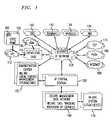
- FIG. 1shows a schematic representation of a broadband network (e.g. broadband IP based network) in accordance with a preferred embodiment of aspects of the present invention.
- a broadband networke.g. broadband IP based network
- FIG. 2shows a block diagram of a preferred embodiment of a centralized control (IP central station) in accordance with aspects of the present invention.
- FIG. 3shows a block diagram of a preferred embodiment of a local control apparatus (broadband residential gateway) in accordance with aspects of the present invention.
- FIG. 4shows a detailed schematic representation of an exemplary embodiment of the broadband network shown in FIG. 1 .
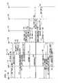
- FIG. 5is a signal flow diagram illustrating a typical on-network to off-network call according to one preferred method of operating the broadband network shown in FIG. 1 .
- FIG. 6is a signal flow diagram illustrating a typical on-network to on-network call according to one preferred method of operating the broadband network shown in FIG. 1 .
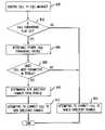
- FIG. 7is a flow chart which illustrates a call forwarding operation in the IP telephony system according to one embodiment of the present invention.
- FIG. 8is a flow chart which illustrates a call forwarding operation in the IP telephony system according to one embodiment of the present invention.
- the broadband networkgenerally provides interconnection between a plurality of customer locations utilizing various interconnection architectures including Internet Protocol (IP) based network, various existing systems (legacy systems) such as the public switched telephone network (PSTN), ATM networks, the Internet, signaling networks, as well as other systems.
- IPInternet Protocol
- PSTNpublic switched telephone network
- ATM networkssuch as the public switched telephone network (PSTN)
- PSTNpublic switched telephone network
- signaling networkssuch as the public switched telephone network (PSTN), ATM networks, the Internet, signaling networks, as well as other systems.
- IPInternet Protocol
- IPInternet Protocol
- the broadband network 1may include one or more customer premises equipment (CPE) units 102 .
- the customer premise equipment 102may be variously configured.
- the customer premise equipment 102may include one or more local control devices such as a broadband residential gateway (BRG) 300 .
- BRGbroadband residential gateway
- the broadband residential gatewayis preferably disposed in a residence for many aspects of the invention, in exemplary embodiments, it may also be disposed in a business or other location.
- the broadband residential gateway 300may be variously configured to provide one or more integrated communication interfaces to other devices within the customer premise equipment 102 such as televisions (TV), personal computers (PC), plain old telephone system (POTS) phone(s), video phones, IP enabled phones, and other devices.
- TVtelevisions
- PCpersonal computers
- POTSplain old telephone system
- the broadband residential gateway 300may provide one or more telephone port connections (e.g., plain old telephone system), Ethernet connections, coaxial connections, fiber distributed data interface (FDDI) connections, wireless local area network (LAN) connections, firewire connections, and/or other connections to a plurality of devices such as plain old telephones, IP based phones, television converters, e.g., cable television (CATV) set top devices, televisions, digital televisions, high definition televisions (HDTV), video phones, and other devices.
- the broadband residential gateway 300may support communications between any of the aforementioned devices in intra-premises calling and/or extra-premises calling. Further, when the broadband residential gateway 300 is used in a business environment, it can function as a private branch exchange or key type telephone system.
- broadband residential gateway 300is illustrated as a single physical device. This configuration is appropriate where centralization of maintenance and control is desirable. Alternatively, the broadband residential gateway 300 may be separated into more than one physical device allowing functionality to be distributed to a plurality of different physical locations in the customer premise and/or broadband network 1 . However, in many embodiments, having a centralized broadband residential gateway 300 located in a single location provides ease of maintenance, control, and re-configuration as well as a reduction in cost due to shared functionality. For example, the broadband residential gateway may be configured to provide the intelligence needed to allow each of the customer premises equipment devices to operate within the broadband network 1 . For example, analog voice may be converted to digital data and packetized for transmission in an appropriate output protocol such as an Internet protocol (IP).
- IPInternet protocol
- the broadband residential gateway 300may function to couple devices within the customer premise equipment 102 to the rest of the broadband network 1 using any suitable broadband communication mechanism.
- the broadband residential gateway 300utilizes a hybrid fiber-coaxial plant 112 to couple the broadband residential gateway 300 to the rest of the broadband network 1 .
- the hybrid fiber-coaxial plant 112may be preferred in many embodiments over other broadband communication mechanisms because of the large number of homes currently connected to cable networks, the capacity for shared access, and the ability for asymmetric data access speeds which allow high quantities of data to be distributed to the various devices in the customer premises equipment 112 .
- the hybrid fiber-coaxial plant 112may include coaxial cable and/or optical fiber networks in any suitable combination.
- the hybrid fiber-coaxial plant 112may provide an intelligent broadband conduit between the broadband residential gateway 300 and a gateway such as the head-end hub (HEH) 115 .
- the head-end hub 115may be variously configured to provide various services and/or interconnections with the rest of the broadband network 1 .
- the head-end hub 115may provide an interconnection point to gather and aggregate external services (e.g., off air and satellite video, public switched telephone network voice, multimedia messages, and Internet data) for distribution to and from the hybrid fiber-coaxial plant 112 .
- the head-end hub 115may function as intelligent conduit for connection and communication between the hybrid fiber-coaxial plant 112 and external networks such as an IP network 120 and/or an ATM/frame relay/cell relay network 185 .
- the broadband network 1may include any number of interconnected head-end hubs 115 , IP networks 120 , and/or ATM networks 185 . Further, the IP network 120 and/or ATM network 185 may be connected to one or more other networks and devices such as:
- the IP network 120 and/or ATM network 185may include one or more routers and/or other devices to route, for example, telephony calls, multimedia calls, signaling messages, administrative messages, programming messages and/or computer data between the various devices in the broadband network 1 such as the head-end hub 115 , the public switched telephone network 160 , the private branch exchange (PBX) 146 , as well as the other devices discussed above.
- the information traveling in the IP network 120may be packetized and formatted in accordance with one of the Internet protocols.
- the IP network 120may also include gateways to interface with the various other networks and/or devices. For example, the gateways may be distributed at the edge of the IP network where the IP network interfaces with one of the other devices or networks.
- the gateways interfacing the IP central station 200 to, for example, the Internet 180 , public switched telephone network (PSTN) 160 , signaling system 7 (SS7) 170 , wireless networks 144 , ATM/frame/cell relay networks 185may be provided in the IP central station 200 , or in both the IP network 120 and the IP central station 200 , and/or partially distributed between the IP network 120 and the IP central station 200 .
- PSTNpublic switched telephone network
- SS7signaling system 7
- wireless networks 144wireless networks 144
- ATM/frame/cell relay networks 185may be provided in the IP central station 200 , or in both the IP network 120 and the IP central station 200 , and/or partially distributed between the IP network 120 and the IP central station 200 .
- an appropriate transport protocolmay be utilized to logically connect the IP central station 200 to the particular gateway.
- the IP central station(s) 200may be connected to, for example, one or more IP networks 120 , ATM networks 185 , secure management data networks 190 , and/or administration centers 155 .
- the IP central station 200may be variously configured to include one or more servers and/or one or more gateways.
- the servers and gatewaysprovide the necessary intelligence and traffic management capabilities to enable information, e.g., IP telephony signals, to travel through the broadband network 1 .
- the IP central station 200may be configured to manage voice information transfer from the public switched telephone network 160 , through the IP network 120 , and into and out of one or more devices such as those connected to a broadband residential gateway 300 .
- the IP central stationmay be configured to store various control and system information such as location, address, and/or configurations of one or more broadband residential gateways 300 , as well as other routing and call set-up information.
- one or more administration centers 155may be connected to the IP network 120 and provide billing and local directory number portability administration.
- the local number portabilitymay be handled by one or more Local Service Management System (LSMS) which may be included in the administration center 155 and/or in the IP central station 200 .
- the Secure Management Data Network 190may also include a mechanism for transferring various information such as billing, call tracking, and/or customer service provisioning.
- Various existing systemsmay be utilized to provide this information such as existing billing systems (OSS) 195 and/or one or more network operations center (NOC).
- the network operations centersmay be included in the administration center 155 , the IP central station 200 , and/or the billing system 195 .
- the network operations center (NOC)may be variously configured to include a translation server to allow communications with the various disparate entities (e.g., legacy systems) in the broadband network 1 .
- the IP network 120 and/or the ATM network 185 illustrated in FIG. 1may include one or a plurality of sub-networks.
- Each of the sub-networksmay include its own IP central station 200 in a distributed configuration, with certain routing data replicated across all IP central stations or each sub-network may be connected to a single centralized IP central station 200 .
- each sub-networkmay be connected to multiple head-end hubs 115 .
- each head-end hub 115may be connected to multiple hybrid fiber-coaxial plants 112
- each hybrid fiber-coaxial plant 112may be connected to multiple pieces of customer premises equipment 102 and/or broadband residential gateways 300 .
- the IP network 120provides an interconnected broadband network which may be utilized to transport and route packetized information to and from diverse geographic locations and may be used on a national or international basis. Further, the IP network 120 and/or ATM network 185 may utilize private network facilities and/or may be provisioned over a shared network such as the Internet.
- the IP central station 200may be configured to provide connectivity for the broadband residential gateway 300 to the Internet 180 (e.g., World Wide Web (www)), as well as connectivity to other external networks such as public switched telephone network 160 and signaling system 7 (SS7) 170 for end-to-end voice, multimedia, and data applications, for example voice over IP telephony.
- IP packets traveling through the IP networkprovide for priority so that, for example, voice packets are given priority over data packets to maintain certain VoIP telephony QoS requirements and a leased line concept for packet traffic which may have an even higher priority.
- the systemis sufficiently flexible so that the priority can be dynamically altered according to customer preferences, variable billing rates, traffic patterns, and/or congestion.
- the IP central station 200may be variously configured. In preferred embodiments, it may be configured to ensure seamless integration of IP based communication system including the IP network 120 with the public switched telephone network 160 , signaling system 7 (SS7) network 170 , and the Internet 180 so that packetized data, for example, voice calls and information data, is properly transferred between the broadband residential gateway 300 , the public switched telephone network 160 and/or the Internet 180 .
- the hybrid fiber-coaxial plant 112 , head-end hub 115 , and IP network 120provide a virtual signaling conduit for packetized voice and data which may, with the coordination of the IP central station 200 , be provided in the appropriate format between the broadband residential gateway 300 and the public switched telephone network 160 and/or Internet 180 .
- the IP central station 200may include a central router 210 , for example, a gigabit switch, which may be utilized to interconnect various servers and gateways contained in the IP central station 200 .
- the central router 210provides for example Ethernet switching and aggregate traffic between servers, gateways and the IP network 120 and/or ATM network 185 backbone.
- the central router 210provides high-speed, non-blocking IP and IP multicast Layer 3 switching and routing.
- the IP central station 200may include one or more of the following servers: the least cost server (LCS) 255 , the time of day (TOD) server 212 , the dynamic host control protocol (DHCP) server, the trivial file transfer protocol (TFTP) server, and the domain name service (DNS) server 214 , the system management (SM) server 216 , the call manager (CM) server 218 , the announcement server (AS) 220 , the multimedia server (MS) 222 , and/or the conference server (CS) 224 .
- the serversmay be separate servers, for example the call manager server 218 , or may be incorporated into a single server.
- the dynamic host control protocol server 131the dynamic host control protocol server 131 , trivial file transfer protocol server 132 , and the domain name service server 214 are each incorporated in a single server facility.
- Each server in the IP central station 200may include computer(s), storage device(s), and specialized software for implementing particular predefined functions associated with each server.
- the servers in the IP central stationmay be provisioned as a main server and one or more back-up servers to provide redundant processing capabilities.
- the routermay be implemented as a main router and a back-up router with similar routing functionality.
- the IP central station 200may also include, for example, one or more of the following gateways; an element management gateway (EMG) 238 , an accounting gateway (AG) 240 , an Internet (Boarder) gateway (IG) 236 , a signaling system 7 (SS7) gateway (SG) 234 , a voice gateway (VG) 232 , and/or a multimedia gateway (MG) 230 .
- the IP central station 200may utilize one or more of these gateways to provide centralized system intelligence and control of voice and/or data IP packets.
- the dynamic host control protocol server 131 and domain name service server 214may operate to dynamically assign IP addresses devices in the customer premise equipment 102 .
- the customer premises equipmentmay be provided with one or a plurality of dynamic IP assignment when activated initially, and/or at the initiation of each active secession.
- an IP addressis assigned when the device is initially activated, it may be desirable to assign a single IP address to a single broadband residential gateway and assign a port address to devices connected to the broadband residential gateway 300 .
- an individual IP addressmay be assigned to each device coupled to the broadband residential gateway 300 .
- the broadband residential gatewaymay include and/or be coupled to one or more cable modems, IP phones, plain old telephone system phones, computers, wireless devices, CATV converters, video phones, and/or other devices which each may be assigned a unique static and/or dynamic IP address and/or a port of a one of these IP addresses.
- the particular protocol for allocating IP addresses and/or portsmay be specified using protocols defined in the dynamic host control protocol server 131 .
- the dynamic host control protocol server 131 and DN server 214may be configured to assign available IP addresses from address pools based, for example, on the identity or type of requesting device, the amount of use expected for the requesting device, and/or predefined assignment protocols defined in the dynamic host control protocol server 131 and DN server 214 .
- CMcall manager
- the trivial file transfer protocol (TFTP) server 132may be configured to transfer certain information to/from one or more broadband residential gateways 300 .
- the trivial file transfer protocol server 132provides Data Over Cable Service Interface Specifications (DOCSIS) configuration information containing QoS parameters and other information required for the broadband residential gateway 300 to operate optimally.
- DOCSISData Over Cable Service Interface Specifications
- the system management (SM) server 216may include responsibility for the overall operational state and functioning of components in the broadband network 1 , either alone, or in combination with other system management servers 216 .
- the system management (SM) server 216may be variously configured to provide monitoring and administrative functions for devices within the broadband network 1 .
- the system management server 216may be configured to provide management of various database functions, memory buffer functions, and software utility functions within the broadband network 1 .
- Software managementincludes, for example, version control, generic control, and/or module control.
- the system management (SM) server 216may include responsibility for the overall operational state and functioning of components the broadband network 1 , either alone, or in combination with other system management servers 216 .
- the system management (SM) server 216may be variously configured to provide monitoring and administrative functions for devices within the broadband network 1 .
- the system management server 216may be configured to provide management of various database functions, memory buffer functions, and software utility functions within the broadband network 1 .
- Software managementincludes, for example, version control, generic control, and/or module control.
- the least cost server (LCS) 255may be variously configured to enable the system to determine the least cost routing of telephone and data transmission throughout the network.
- the least cost server 255may also provide one or more broadband residential gateway users capability to select between, for example, cost and Quality of Service (QoS).
- QoSQuality of Service
- the announcement service (AS) server 220may be variously configured. In exemplary embodiments, it may store and send announcements to specified destinations and/or all destinations based on instructions received by, for example, the call manager (CM) server 218 .
- the announcement server 220receives, for example, Media Gateway Control Protocol (MGCP) or later signaling (e.g., H.GCP—an ITU standard Gateway Control Protocol) control messages from the call manager 218 , and sends announcements to one or more voice gateways (VG) 232 and/or the one or more broadband residential gateway 300 (e.g., using Real Time Protocol (RTP) packets).
- MGCPMedia Gateway Control Protocol
- H.GCPan ITU standard Gateway Control Protocol
- the announcement server 220may send an announcement once, a predetermined number of times, or in a continuous loop.
- the announcement server 220may detect when a phone or other device has been taken off-hook and play an advertisement or other announcement to the user. Where a user has signed-up for an advertising plan whereby phone rates are reduced in return for advertising revenue generated by the advertisements, the announcement server 220 may be utilized to track the number of individuals with a particular income, age, or other profile which hear the advertisement. The announcement server 220 may respond to requests from individual system devices such as one of the broadband residential gateways 300 and/or under control of, for example, the call manager 218 . Where the announcement server is under control of the call manager 218 , the call manager may be configured to control various operating parameters of the announcement server. For example, the call manager 218 may request that certain announcements are sent once, a specified number of times, or in a continuous loop.
- announcementsmay be generated elsewhere in the broadband network 1 , stored as files, and distributed to one or more announcement servers via a file transfer protocol or resource such as the trivial file server 214 using one or more file transfer protocols.
- the announcementmay have an audio component and/or a audio/video component.
- the audio/video componentmay be stored using a combination of an encoding format (e.g., G.711) and/or a standard file format such as wave (WAV), MPEG, and other suitable formats.
- a userpicks up a telephone which sends a signal to the call manager 218 .
- the call manager 218may establish a connection to the announcement server 220 and play one or more pre-recorded and/or predetermined announcement (hypertext and/or audio).
- Signaling tonessuch as a busy signal may be played by the broadband residential gateway 300 or the call manager 218 , but Special Information Tones (SIT) and/or messages may also be included as part of an announcement file.
- SITSpecial Information Tones
- the announcement server 220may have information entered by a user using, for example, a broadband residential gateway to provide additional information to the called party.
- the additional informationmay include the ability to leave a message, type-in a chat note, page the called party, barge-in on the call, and/or other user or system defined call handling capabilities.
- the announcement server 220may also be programmed with various system messages such as an announcement indicating that a number dialed is incorrect or that the call did not go through as dialed, that the lines are busy, that all liens between two countries are currently busy, that the called party has changed numbers, that the called parties party's phone has been disconnected, that one or more system errors have occurred, and/or other announcement messages.
- system messagessuch as an announcement indicating that a number dialed is incorrect or that the call did not go through as dialed, that the lines are busy, that all liens between two countries are currently busy, that the called party has changed numbers, that the called parties party's phone has been disconnected, that one or more system errors have occurred, and/or other announcement messages.
- the call manager (CM) 218may be variously configured.
- the call manager 218provides a centralized call control center for supporting call set-up and tear-down in the broadband network 1 .
- the call manager 218may be configured to include trunk and line information maintenance, call state maintenance for the duration of a call, and/or user service features execution.
- the call manager 218may also provide for call processing functions such as a standardized call model for processing the various voice connections such as voice over IP calls.
- a standardized “open” call modelmay be utilized which supports standardized application programming interfaces (APIs) to provide transport services and other user functions such as calling cards.
- APIsapplication programming interfaces
- An open application programming interface and call set-up interface in the call managerwill enable third party applications to be loaded into the call manager 218 and broadband residential gateway 300 . This will facilitate the development of third party applications for enhancing the functionality of components in the broadband network 1 .
- third parties and other equipment vendorsmay manufacture various broadband residential gateways 300 for use in the broadband network 1 by writing applications to support the open call model of the call manager 218 .
- the call manager 218 and/or broadband residential gateway 300may also be configured to execute and/or accept commands from a standardized scripting language which may generate instructions for the call manager 218 and/or broadband residential gateway 300 to execute various functions.
- the scripting functionalitymay include the ability to execute an entire call model including interfaces to the signaling system 7 (SS7) 170 , the public switched telephone network 160 , IP network 120 , ATM/frame/cell relay network 185 , and/or other functions within, for example, IP central station 200 such as the multimedia server 222 , announcement server 220 , system management server 216 , conference server 224 , time of day server 212 , least cost server 255 , and/or domain name server 214 .
- SS7signaling system 7
- the call manager 218may also be configured to maintain the call states for each call it handles (e.g., a voice over IP call) and respond to system events created by, for example, the multimedia gateway control protocol (MGCP) messages and/or integrated services digital network user part (ISUP) messages for signaling system 7 (SS7) protocol that may occur during the processing of a call.
- MGCPmultimedia gateway control protocol
- ISUPintegrated services digital network user part
- SS7signaling system 7
- Exemplary events handled by the call manager 218include call state changes, call feature changes/call feature triggering events, changes in the status of lines and trunks, and/or error conditions.
- the call manager 218may interact with devices connected to a single circuit on the public switched telephone network 160 and/or a device connected to a port of the broadband residential gateway 300 . In this manner, new devices may be added to the infrastructure and operate using the open call model contained in the call manager 218 .
- the call manager 218may also include storage for subscriber and network configuration, a cache server for faster access to frequently used data, a routing engine for selecting an appropriate routing algorithm (e.g., least cost routing), and/or a service broker which provides the data and logic for specific services.
- the call manager 218may include an authentication (AC) server 245 that provides authentication of various devices, objects, packets and users in the integrated multimedia system. In this manner, a user may verify the identity of the calling or called party.
- ACauthentication
- the call manager 218may interact with the signaling gateway (SG) 234 , the accounting gateway (AG) 240 , the element management gateway (EMG) 238 , the voice gateway (VG) 232 , and the multimedia gateway (MG) 230 using any suitable protocol such as IP and an interconnection mechanism such as the central router 210 .
- the call manager 218may be configured to utilize signaling messages such as: a) ISUP messages over Common Object Broker Architecture (COBRA) interface to and/or from signaling gateway 234 , b) MGCP, SIP—simple internet protocol, H.GCP, and/or other suitable control messages to and/or from the announcement server 220 , c) call event records in modified Radius format to the accounting gateway 240 , d) Radius (or Enhanced Radius or compatible protocol) control messages to and/or from the voice gateway 232 and/or the broadband residential gateways 300 , and e) signaling network management protocol (SNMP) messages to and/or from the element management gateway 238 .
- signaling messagessuch as: a) ISUP messages over Common Object Broker Architecture (COBRA) interface to and/or from signaling gateway 234 , b) MGCP, SIP—simple internet protocol, H.GCP, and/or other suitable control messages to and/or from the announcement server 220 , c) call event records in modified
- the call manager 218may incorporate one or more databases.
- the call manager 218may include database information such as (1) a resources database that provides an identification of what resources are connected to the broadband network 1 and their current state; (2) a trunk/gateway database that indicates which gateway serves what circuits in a trunk; (3) a customer database which indicates whether a call is authorized, identifies what services a line supports and determines whether a telephone number is on or off the integrated IP communication network; (4) a numbering plan/least cost routing database which provides routing information that enables the IP central station 200 to choose the correct trunk as a function of the call number; and (5) a local number portability (LNP) database that indicates the North American Numbering Plan (NANP) and associated prefixes which are open for association with the number portability service; and (6) an address of the service control point (SCP) towards which requests for translating these local portability numbers should be routed.
- database informationsuch as (1) a resources database that provides an identification of what resources are connected to the broadband network 1 and their current state; (2)
- the broadband network 1includes equipment compatible with the COBRA standard.
- COBRAmay be utilized to allow applications from a plurality of vendors to operate with each other.
- the COBRA standardallows a company, such as AT&T, to build its network using multi-vendor equipment and yet ensure seamless integration and operation.
- Some of the major areas covered by COBRA v. 2.2includes: Inter-ORB Bridge Support, General Inter-ORB Protocol (GIOP) support, Internet Inter-ORB Protocol (IIOP) support, and Environment Specific Inter-ORB Protocol (ESIOP) support.
- GIOPGeneral Inter-ORB Protocol
- IIOPInternet Inter-ORB Protocol
- ESIOPEnvironment Specific Inter-ORB Protocol
- the call manager 218may integrate these protocols to facilitate call set-up with diverse equipment. This is advantageous in that equipment from a plurality of vendors may interoperate over the broadband network 1 without modification.
- the multimedia server (MS) 222may be variously configured.
- one or more multimedia serversmay provide support for multimedia messaging service and/or the overall management of multimedia voice and mail messages transmitted across the broadband network 1 .
- the multimedia servermay be configured to support e-mail (e.g., html) messages, voice mail (audio) messages, and/or video mail (audio and video) messages.
- the multimedia messagesmay include standard pre-configured system messages, advertising messages, and/or user defined messages. In either event, where the messages are stored in a centralized location, the multimedia server may provide such storage.
- a databasemay be utilized for indexing, storage, and retrieval of such messages.
- the usermay access predetermined ones of these messages.
- the multimedia server 222may utilize IP as a method of communicating with other devices across the broadband network 1 .
- the conference server (CS) 224may be configured to provide for multiparty conference calls using, for example, IP voice packets during an IP telephony or multimedia session call.
- the conference server 224may include specialized software that runs on a computing platform having associated multiplexing and demultiplexing capability for segregating and aggregating user information packets. For example, the conference server may log several calls into a conference session. When information packets are sent from one or more phones, they are aggregated and sent to the other phones on the conference call.
- the conference server 224may use any suitable communication protocol such as H.GCP or SIP.
- the conference server 224may function to aggregate user information from two or more users onto a single call path.
- the conference server 224may include one or more “call-in numbers” and be controlled from any location, e.g., a centralized operator location and/or one or more broadband residential gateways 300 . It may be desirable to have the conference server 224 configured such that some callers simply monitor the call without voice interruption while other callers have both voice transmit and receive capabilities. Where a caller is not given the privileges associated with active participation in the call, voice packets from these users are discarded. For example, a CEO may have a conference call with a plurality of financial advisors and invite the press to listen on the call without interruption capabilities.
- the gateways in the IP central station 200may be configured to provide translation of signals to and/or from the various servers in the IP central station 200 , the IP network 120 , the public switched telephone network 160 , the signaling system 7 (SS7) network 170 , the Internet 180 , and/or the secured management data (SMD) network 190 .
- the gatewaystypically support one or more of the following group of functions: call processing; signaling system 7 (SS7) connectivity; billing support; OAM&P support; connection to public switched telephone network; control CoS/QoS parameters; and enhanced services.
- the voice gateway (VG) 232may be connected to the public switched telephone network 160 and operate to convert between IP based voice packets and standard public switched telephone network 160 voice traffic.
- Voice gateway 232may be configured as multi-frequency (MF) or ISUP gateways on a per-T1 basis. Where multi-frequency (MF) trunks are used, one embodiment utilizes signaling between the call manager 218 and the voice gateway 232 using MGCP, SIP, H.GCP and/or other compatible protocol. Multi-frequency trunks may be compatible with Feature Group D (FGD), Operator Service (OS) Signaling protocol and/or Termination Protocol (TP).
- FGDFeature Group D
- OSOperator Service
- TPTermination Protocol
- the IP central station 200may be variously connected to the public switched telephone network network.
- the IP central station 200may be connected directly to the public switched telephone network using, for example a bearer channel (e.g., a T1 or T3 carrier) and/or interconnected using one or more networks such as an IP network and/or ATM/frame/cell relay network 185 .
- a bearer channele.g., a T1 or T3 carrier
- the service bureau in the public switched telephone network 160may be interconnected using an alternative network arrangement such as an IP network 120 and/or a ATM/frame/cell relay network 185 .
- the service bureaumay coordinate with the IP central station 200 in providing operator services, directory services and provisioning for 311, 611, and 711 services.
- Emergency 911 servicesmay be routed to an E911 tandem switch that has the appropriate databases and interfaces with a Public Safety Answering Position (PSAP).
- PSAPPublic Safety Answering Position
- Emergency 911 servicesmay be coordinated by the call manager 218 and/or public switched telephone network based service bureau.
- Voice gateway 232may be router-based and include one or more voice feature cards and/or DSP Module cards to perform voice processing.
- the voice gateway 232may optionally include host processors, LAN/WAN ports, Ethernet ports, T1 or E1 telephony interface cards, Voice Feature Cards with DSP Modules providing voice compression transcoding (G.711 and G.729), carrier-quality echo cancellation with 8 ms-32 ms tail length, a de-jitter buffer which adapts to delay variations in the network in order to minimize the delay, packet loss concealment that generates concealment frames for lost packets using information from previously received data, and/or tone detection and generation.
- This functiondetects Multi-Frequency (MF) tones and generates MF and call processing tones (e.g. dial tone, call-waiting tone etc.).
- MFMulti-Frequency
- the voice gateway 232may include T1/E1 interfaces with internal Channel Service Units (CSUs). It may also be desirable to configure the voice gateway 232 such that ISUP, MF and Centralized Attendant Services (CAS) trunks are supported with a configuration done on a per T1 basis. Additionally, multi-frequency tones and Centralized Attendant Services may utilize a “robbed bits” communication scheme where bits are “robbed” from sub-frames to transmit in-band signaling. The multi-frequency tones may be converted to and/or from, for example, simple gateway control protocol (SGCP) signal requests and events by the voice gateway 232 .
- SGCPsimple gateway control protocol
- multi-frequency tones and/or lower level signaling and timing functionsmay be translated to and/or from any of the following indications: simple gateway control protocol Notify functions, simple gateway control protocol Notification Requests, Connection requests, Modify Connection requests, off-hook and/or on-hook indications.
- An Ethernet interface with a RJ-45 connectormay be used to connect the voice gateway 232 to the central router 210 (e.g., Gigabit Switch or High Speed Router (HSR)).
- the multimedia gateway control protocolmay be used as the interface between the voice gateway 232 and the call manager 218 .
- call control, signaling, and multimedia data stream, real time protocol (RTP) connections, IP addresses, UDP ports, codec choice etcmay be configured in any suitable manner such as by using a multimedia gateway control protocol.
- audio streamsmay be passed directly between customer premises equipment 102 using real time protocol connections over, for example, a user datagram protocol (UDP).
- UDPuser datagram protocol
- the multimedia gateway control protocolmay be utilized to request the voice gateway 232 to initiate, cancel, and/or otherwise modify connections in order to set up and tear down RTP media streams.
- a similar proceduremay also be utilized to request continuity tests and results.
- the IP network 120 and/or ATM/frame/cell relay network 185may be utilized to interconnect a plurality of ESS switches to transport signaling information, voice, and/or data.
- SS7Signaling system 7
- TCAPTransaction Capabilities Application Part
- the transport of signaling system 7 (SS7) transaction capabilities application part (TCAP) messages over the packet networksallows signaling operations to be supported by multiple connections to the same host, multiple host connections, and distributed processing of call set-up information using, for example, multiple call managers 218 in the broadband network 1 .
- the IP network 120 and/or ATM/frame/cell relay networkmay be utilized to interconnect a plurality of ESS switches to transport signaling information, voice, and/or data.
- the signaling gateway (SG) 234is configured to support signaling system 7 (SS7) signaling transport using transaction capabilities application part (TCAP) messages
- SS7signaling system 7
- TCAPtransaction capabilities application part
- MGCPmultimedia gateway control protocol
- TCAPtransaction capabilities application part
- ISUPISDN User Part
- the point where ISUP and TCAP messages are terminated at a signaling system 7 (SS7) signaling gatewayis defined as a Service Switching Point (SSP) to the signaling system 7 (SS7) network 170 .
- the call manager 218may be configured with a standardized Application Programming Interface (API) to allow interaction with the signaling system 7 (SS7) by, for example, sending and/or receiving ISUP and TCAP messages from a service switching point (SSP).
- Full class 5 signaling system 7 (SS7) functionalitymay be included in the call manager 218 including the ability to provide all of the information necessary for billing as defined in the GR-246-Bellcore standard.
- the signaling gateway 234may be arranged to perform: signaling system 7 (SS7) message handling (message discrimination, message distribution, and message routing); signaling link management (e.g., link activation, deactivation); signaling route management (managing Point Code [PC] route status based on route received management messages such as Transfer Prohibited, Transfer Allowed, Transfer Restricted, etc.); and signaling traffic management (diversion of traffic based on unavailability, availability, restriction of signaling link, route, and Point Code.)
- the signaling system 7 (SS7) architecturesupports the necessary redundancy component scheme for system reliability and availability during scheduled maintenance and/or software/hardware upgrades.
- the signaling gateway 234may be configured to directly provide for lower level signaling system 7 (SS7) processing.
- the signaling gateway 234interacts with the call manager 218 using an appropriate open interface (e.g., Common Object Request Broker Architecture (COBRA)).
- COBRACommon Object Request Broker Architecture
- MTPMessage Transfer Part
- the complete signaling system 7 messagemay then be sent to the Signaling Transfer Point (STP) in the external signaling system 7 (SS7) network 170 .
- STPSignaling Transfer Point
- the signaling gateway 234may be configured to remove ISUP or TCAP application layer data from the signaling system 7 (SS7) messages received from the STP prior to converting the information to an appropriate open interface (e.g., COBRA) and forwarding the information to the call manager 218 via the central router 210 .
- SS7signaling system 7
- the accounting gateway (AG) 240may be configured to receive messages representing events from the call manager 218 via a suitable transport mechanism such as the central router 210 . Typically, two messages are received for each call, the first when the call is established, and second when the call terminates. In the case of unsuccessful calls, only the failure message will be logged. The messages provide details about the calling and called parties, the timing of the call set-up, the duration and the quality of the call. Accounting gateway 240 may be duplicated using a redundant computer, with each gateway having dual-mirrored disks. The accounting gateway 240 stores usage records and may then distribute them to linked destinations (e.g., billing centers) for processing. Billing centers typically include bill processors that receive accounting information from the accounting gateway 240 and generate appropriate on-line or paper billing to customers.
- linked destinationse.g., billing centers
- the accounting gatewaymay be configured to accommodate multiple days worth of accounting records such as the records for one day, two days, three days, four days, a week, or a month.
- the period in which the data is retained in the accounting gatewaymay be dependent on business needs, hardware restrictions, and/or the billing cycle. For example, as the end of the billing cycle nears, it may be desirable to shorten the period the accounting gateway holds the data such that calls placed the day the bills are printed are included on the bills. Further, the accounting gateway may both retain and forward data to the billing centers. In this manner, if the equipment at the billing center fails, the accounting gateway 240 may serve as a backup. Similarly, the billing center may act as a backup where the accounting gateway 240 fails.
- An Automatic Message Accounting (AMA) formatis typically used by circuit-switching systems, packet-switching systems, and other network elements to provide billing usage measurements data (e.g., the Bellcore® Automatic Message Accounting Format (BAF)). This data may be utilized either to permit charging the customer for use of network resources or to permit charging other carriers (e.g., InterExchange Carrier (IEC) and other Local Exchange Carrier (LEC)) for assistance in placing call connections.
- the accounting gateway 240may be configured to convert this information into an Automatic Message Accounting Format (AMA) Format (e.g., BAF) records and send these records to the external billing systems using, for example, a TFTP (trivial file transfer protocol).
- AMAAutomatic Message Accounting Format
- Time-stamp accuracyis typically based on the accuracy of the call manager 218 clock which may be derived from the TOD 212 server.
- the event information produced by the call manager 218preferably has appropriate information for the telephone service specified such as phone number of the calling party (customer), phone number of the called party (customer), time of call, duration of the phone call, and use of any discretionary features.
- Different AMA structuresmay be generated between On-Net calls (defined as within a network service provider IP network 120 ) vs. Off-Net calls (defined as outside of service provider IP network—e.g. public switched telephone network) for billing purposes.
- the element management gateway (EMG) 238may provide system management functionality that includes, for example: a) status and performance monitoring for the Operation Administration, Maintenance, and Provisioning center, to gauge the ongoing operation of applications; b) extensive information exchange with a network operations center responsible for ongoing maintenance of one or more applications; c) customizable operations interface to allow the network operations center to view only information required, thus reducing the time spent filtering information; d) centralize distributed application configuration allowing for the centralized configuration of objects residing on a plurality machines; e) proactive network management capabilities to remove the need for constant operator intervention making the day-to-day operations more efficient; and/or f) intelligent display of status information to separate critical issues from low-priority problems allowing the operation center to assign resources to the right problems at the right time.
- EMGelement management gateway
- the multimedia gateway (MG) 230may be configured to connect to the public switched telephone network 160 and to convert IP based multimedia packets into standard public switched telephone network 160 traffic.
- the multimedia gateway 230may include an intelligent trunking interface that communicates with the call manager 218 for automatic trunk sizing and allocation between the IP network 120 and the public switched telephone network 160 .
- the communication sessioninvolves the transmission of video and audio data.
- the bandwidth that is required for this type of communicationis much greater than that required for a PSTN-to-PSTN voice call or an IP-to-PSTN voice call.
- the multimedia gateway 230may negotiate a larger bandwidth to facilitate the call if the called party is also video enabled. This bandwidth negotiation process typically occurs with a 5ESS or a Local Digital Switch within the public switched telephone network 160 .
- a multimedia callincluding live video, audio and data, will require bandwidth ranging from 56K to 1.544 Mbps.
- the multimedia gateway 230must be able to monitor bandwidth usage and make appropriate adjustments so as to maintain an acceptable quality of service.
- the Internet gateway (IG) 236may be connected to the Internet (e.g., World Wide Web (www)) and provide a means for IP based data packets to be routed between the IP network 120 and the Internet 180 .
- IP based voice packetsmay be routed via the Internet 180 .
- the Internet gateway 236routes data-only packets which share the same priority level with other lower priority, non-real-time traffic consistent with computer data communications presently experienced with the Internet 180 . Consequently, low priority and low latency data traffic on the IP network 120 utilize the Internet gateway 236 to communicate with other IP data networks such as the www.
- Voice packetsmay be routed through another network such as the ATM/frame/cell relay network 185 , a private IP network 120 , and/or the public switched telephone network 160 where committed information rates may be easily obtained.
- the broadband network 1includes the interfaces which enable connections to existing Operation, Maintenance and Provisioning (OAM&P) 195 systems that support, billing, accounting, provisioning and/or configuration management functions.
- a Secured Management Data (SMD) Network 190may be utilized to connect the OAM&P 195 to the accounting gateway 240 and element management gateway 238 .
- the Secure Management Data network 190may include a Network Service Division's NSD Net.
- the Secure Management Data network 190helps ensure that only secure communication can occur between the IP central station 200 and the OAM&P 195 . This eliminates one potential means of tampering with the billing and provisioning functions in the OAM&P.
- the billing systems (OSS) 195may include the Network Operations Center (NOC).
- NOCNetwork Operations Center
- the NOCmay include a translation server which includes functions for allowing communications and control of diverse networks.
- BRGBroadband Residential Gateway
- the broadband residential gateway 300may be configured as the interface unit between the remainder of the customer premise equipment 102 devices and the external network.
- the broadband residential gateway 300may be connected to the remainder of the broadband network 1 using any suitable mechanism such as a gateway directly into an IP network and/or a cable connection.
- a hybrid fiber-coaxial plant connectionis utilized such as hybrid fiber-coaxial (HFC) plant 112 .
- the hybrid fiber-coaxial plant 112allows numerous broadband residential gateways 300 to be included on an existing hybrid fiber-coaxial plant 112 without modification to the plant's infrastructure.
- the broadband residential gateway 300may be variously configured to, for example, provide high-speed cable modem capabilities to interconnect one or more associated PCs with each other and with the remainder of the broadband network 1 , provide functionality to one or more TVs (using, for example, either an integrated or separate decoder functionality, e.g., set top box 350 ), one or more telephone connections such as plain old telephone service (POTS) phones and/or digital telephones, displays, wireless interfaces, voice processing, remote control interface, display interface, and/or administrative functions.
- POTSplain old telephone service
- the broadband residential gateway 300may a) providing conversion between analog voice and IP voice packets, b) multiplexing/demultiplexing streams of IP voice packets, c) supporting multiplexing/demultiplexing of multiple incoming and outgoing signals including multiple voice, multimedia, data, system administration, and/or TV information signals.
- the interconnectionmay be provided by one or more data buses, for example, a high speed bus (HSB) 360 , processor bus 380 , and/or other interconnection system.
- the high speed bus 360may be configured to provide a flexible conduit for transferring information between the internal hardware, processors and ports.
- the high speed bus 360may include one or more of the following functional units a) a universal remote control receiver module 365 for receiving wireless (e.g., infrared, and/or RF) signals (e.g., keyboard signals and/or remote control signals) for control of the broadband residential gateway 300 and/or any connected devices, b) a display, display driver, touch screen logic module for driving one or more local and/or remote displays for interfacing with the broadband residential gateway 300 and/or one or more connected devices, c) one or more TV port modules 336 for interconnecting televisions, set-top devices, and/or other audiovisual devices to the broadband residential gateway 300 , d) one or more data port modules 334 for connecting/interconnecting data enabled devices (e.g., personal computers, palm top devices, etc.), e) one or more telephony port modules 332 for interconnecting one or more analog and/or digital telephones, f) one or more peripheral port modules 342 for interconnecting one or more of the broadband residential gateway 300 .
- wireless
- the modulesmay include a telephony processing module (P 1 ) 308 , data processing module (P 2 ) 310 , video processing module (P 3 ) 312 , auxiliary processing module (P 4 ) 314 , IP processing module (P 5 ) 316 , and/or an operations administration maintenance and provisioning processing module (P 6 ) 318 interconnected through one or more busses such as processor bus 380 .
- the processor bus 380 and/or high speed bus 360may include any suitable interconnect bus including intelligent bus configurations incorporating smart buffer logic (not shown in FIG. 3 ) to facilitate data transfer between interconnected processors and/or modules.
- the various modules and/or processing components of the broadband residential gateway 300may be powered by, for example, a power supply unit (not shown). Each of the individual modules of the broadband residential gateway will now be described in more detail.
- the transceiver 302may include circuits for converting digital signals to and from RF signals suitable for transmission across a broadband network such as the hybrid fiber-coaxial plant 112 .
- the transceiver 302may include one or more input/output ports such as a cable interface (e.g., an F connector cable connection) and/or a fiber optic interface connected to a communication media (e.g., hybrid fiber-coaxial Plant 112 ).
- the transceiver 302may be compatible with the DOCSIS 1.0 or later specifications.
- the broadband residential gateway 300may be compatible with the Media Gateway Control Protocol (MGCP) or other compatible signaling protocol (e.g., SIP or H.GCP) to support telephony applications.
- MGCPMedia Gateway Control Protocol
- SIPSession Initiation Protocol
- H.GCPH.GCP
- the transceiver 302may serve as a modem, a translator and/or a mulitiplexor/demultiplexor. Data received from the network may be de-multiplexed and placed on the data bus for dispatch to the appropriate peripherals and/or ports. Data from the various ports and peripherals may be multiplexed together for distribution over one or more broadband networks (e.g., the hybrid fiber-coaxial (HFC) plant 112 ). Where a hybrid fiber-coaxial plant 112 is utilized, the data may be multiplexed onto various frequency bands of the hybrid fiber-coaxial plant 112 in a continuous data stream(s), and/or packetized data stream(s). To facilitate data transfer for various networks, the transceiver 302 may include one or more registers for data queuing and/or IP tunneling of data packets across the broadband network.
- HFChybrid fiber-coaxial
- a displayis integral to the broadband residential gateway 300
- alternative embodiments of the broadband residential gateway 300may provide a user interface via the TV screen, PC screen, video telephone, and/or other display device in addition to, or in lieu of, a display integral to the broadband residential gateway 300 .
- the peripheral ports module 342may include a plurality of ports providing connectivity to external peripherals.
- Exemplary interfacesinclude, PCI, Firewire, USB, DB25, etc. Devices which incorporate one or more of these interfaces may utilize the broadband residential gateway 300 to interconnect to the remainder of the broadband network 1 .
- the external/internal Intercom Module (IM) 344may include one or more microphones/speakers, voice CODECs, telephony processors, and/or interface ports. Where an intercom module 344 is utilized, the built-in circuitry may be configured to detect, for example, unused plain old telephone system telephone(s) and generates a special intercom tone on these unused telephones. In this manner, existing plain old telephone system telephones, digital phones, and/or other devices may serve as an intercom throughout the residence.
- the controller 306e.g., such as the P 1 telephony processor 308 ) may function to command the intercom module 344 to determine an appropriate intercom path to select an intercom connection between various locations.
- the CODECmay be configured to convert the analog voice signal into IP packets for transmission over one or more data ports 334 , TV ports 336 , display modules 338 , telephony ports 332 , peripheral ports 342 , external/internal intercom ports 344 , wireless interface ports 345 , and/or set-top boxes 350 .
- multiple broadband residential gateways 300may be configured through, for example, IP tunneling, to set-up an intercom connection between multiple remote broadband residential gateways 300 .
- an administrative assistant at the officemay be contacted via an intercom connection present at the user's home.
- one or more individuals disposed at either local and/or remote locations with diverse types of equipmentmay communicate as an intercom group without the need to communicate via normal dialing procedures.
- the intercom module 344may also configure intercom services for other telephony services (e.g., extension transfer, call conferencing, internal caller ID), high speed data services (e.g., LAN connections), facsimile transmission/reception, e-mail transmission/reception, video conferencing, and/or CATV/HDTV (Cable Television/High Definition Television) using standard industry protocols such as DOCSIS 1.0 or higher and IP tunneling transmissions.
- telephony servicese.g., extension transfer, call conferencing, internal caller ID
- high speed data servicese.g., LAN connections
- facsimile transmission/receptione.g., LAN connections
- facsimile transmission/receptione.g., LAN connections
- e-mail transmission/receptione.g., video conferencing
- CATV/HDTVCode Television/High Definition Television
- processingmay be accomplished by a single processor performing all functions (e.g., processing controller 306 ), in the preferred embodiment shown in FIG. 3 , the architecture employs a distributed processing controller 306 , and a plurality of processors P 1 -P 6 308 - 318 .
- each of the plurality of processors P 1 -P 6may be configured to have a dedicated function to provide predetermined services or applications.
- the processorsmay be coupled together via any suitable mechanism such as the processor bus 380 and/or high speed bus (HSB) 360 .
- HSAhigh speed bus
- the first processor P 1 308may include telephony applications such as call set-up, call tear down, and call functions; the second processor P 2 310 may include management functions such as distribution and coordination of data within the various devices of the broadband residential gateway 300 ; the third processor P 3 312 may include video processing functions for configuring control panels, screen displays of attached devices, video conference calls, MPEG decoding functions and other video processing functions; the fourth processor P 4 314 may include an auxiliary processor for off loading special processing functions such as numeric processing; the fifth processor P 5 316 may include interface input/output processing (e.g., text to voice and vise versa) and/or Internet protocol (IP) processing functions for configuring data to communicate with the remainder of the broadband network 1 and/or devices attached to the broadband residential gateway 300 such as IP telephones or IP enable PCs; and the sixth processor P 6 318 may include processing functions for Operation, Maintenance and Provisioning (OAM&P) processing.
- OAM&POperation, Maintenance and Provisioning
- Each of the above processorsmay be an entirely separate processing unit with included RAM, ROM, Flash memory, or may share RAM, ROM, and/or Flash memory. Where shared RAM, ROM, and/or Flash memory is utilized, the memory may be located within the distributed processor controller 306 and/or on the processor bus 380 . Alternatively, the memory may be integrated into the operating program store 330 and/or into memory 322 .
- the Distributed Processing Controller 306 with its associated processors (P 1 -P 6 )may be coupled to the various elements of the broadband residential gateway 300 so as to enable proper operation of each of the individual components.
- the distributed processing controller 306(with any associated processors (P 1 -P 6 )) may also coupled to the security processor, smart card/credit card, and interface module 340 , the peripheral port(s) module 342 , and/or the External/Internal Intercom Module 344 for providing control and coordination among devices coupled to the high speed bus 360 .
- the display 338may include, for example, an interactive LED/LCD module positioned in a suitable location such as within or attached to the broadband residential gateway 300 .
- the display 338may include an interface to notify, display and receive user inputs and processing status.
- the display 338may be configured to display various informational status such as multimedia mail, called ID, call logs, call in progress and associated information, call waiting information, call conferencing, and/or other call related information.
- the display 338may provide a display of real time status of the various devices connected to the broadband residential gateway 300 as well as any current connections, calls, and/or data transfers.
- the display 338may also include touch screen capabilities that allow information to be input via a plurality of interrelated on-screen prompts, on-screen icons, and/or a keypad (e.g., an alphanumeric keyboard).
- the keypadmay be a remote control, numeric keyboard, and/or alphanumeric keyboard.
- a usermay touch an icon representing a pending voicemail and/or multimedia mail message.
- the panelmay be configured to send an electronic signal to the processing controller 306 and/or an attached processor such as the telephony processor.
- the P 1 telephony processor 308may be configured to generate an IP packet via the transceiver 302 across portions of the broadband network 1 to the multimedia server 222 in IP central station 200 .
- the multimedia server 222may authenticate the request by, for example, verifying location of the request and/or the identity of the requesting party. Where identity of the calling party is being verified, the user enter an access password by an audio and/or keyboard request.
- the usermay utilize the external/internal intercom module 344 of the broadband residential gateway 300 , or via a text message entered into the display 338 .
- the usermay then enter the appropriate access code via the onscreen soft keypad, microphone, and/or keyboard.
- the messagecould be stored locally in the broadband residential gateways 300 memory 322 and depending on whether there is a password lock on the broadband residential gateway 300 , the user may not have to enter a password to access the message.
- the display 338simply recalls the message from memory and presents to the user to provide one-touch instant message retrieval.
- the icons on the LCD/LEDmay be personalized to show the identity of the owner of the message.
- Each usermay have a different password to ensure privacy of access.
- An activity logwhich tracks past and present messages and/or archives multimedia messages may be presented on display 338 .
- the archivemay be stored locally, or at a remote location such as IP central.
- the archivemay be utilized by the user to recall messages which have long since been erased from local storage but may be retrieved from IP central on tape and/or disk storage. This is preferably an optional feature for those users who are less security conscious.
- the multimedia messagesneed not be displayed only on display 338 .
- any of the peripheral devices attached to the broadband residential gateway 300are capable of receiving the multimedia messages.
- the memory 322may be variously configured to include one or more field-upgradeable card slots for permitting memory expansion. Certain users may wish to enable higher end applications such as near video on demand (e.g., pausing of shows via buffering in memory), video conferencing of multiple users, multi-party conferences, call waiting for multiple parties, etc. Accordingly, the use of a broadband residential gateway 300 allows the user to upgrade memory via inserting additional cards. Alternatively, the user may use system memory in IP central and buffer data remotely.
- Operating program store 330may be configured to receive updates. This may be accomplished by having the user replace one or more memory cards or automatically by the IP central station downloading new operating code into one or more residential gateways 300 .
- smart buffer logicmay be coupled to the telephony port(s) 332 , data port(s) 334 , TV port(s) 336 , peripheral port(s) 342 , and/or the distributed processing controller (DPC) 306 .
- the smart buffer logicmay function to buffer the IP packets for delivery over the communication network such as the hybrid fiber-coaxial plant 112 .
- the smart buffer logicmay include selectable switching and routing algorithms based on services and applications associated with each port. Depending on the destination of the IP traffic, the smart buffer logic may multiplex signals from various devices to effect faster information transfer.
- the smart buffer logicmay also allow direct memory access between memory 322 and one or more of the devices and/or ports coupled to the high speed bus 360 .
- the telephony port(s) 332may include various interface circuitry (e.g., analog interface, logic and firmware for interfacing with the Plain Old Telephone (POTs) telephones). Also the telephony port(s) 332 may also be configured to include user interface logic, voice processing logic, voice activity detector logic, voice CODECs, and DTMF (dual tone multi-frequency) tone sensing logic. Echo cancellation and automatic gain control may also be utilized in the telephony port(s) 332 circuitry. In one embodiment, RJ-11 connectors for a plurality of lines (e.g., 4) are provided for connection to one or more existing plain old telephone system 110 telephone units. However, the broadband residential gateway 300 may contain any number of telephone connection ports.
- POTsPlain Old Telephone
- any number of existing user phonesmay be connected directly to the broadband residential gateway 300 without modification.
- the broadband residential gatewaycan be configured to support, in addition to as alternative to the plain old telephone system telephone units, ISDN telephones and/or other digital phones (e.g., IP telephones) using an appropriate interface.
- the data port(s) 334 interfacemay be variously configured.
- the data portsinclude high speed data service connections to, for example, a personal computer (PC) using a LAN connection.
- the data ports 334may include an Ethernet 802.3 connection compatible with category 5 unshielded twisted pair (UTP) cable and a RJ-45 connector.
- the data port(s) 334may include the necessary interface circuitry for coupling to remote computers.
- the TV port(s) 336may include an interface for conventional television, HDTV and/or CATV services.
- the TV port(s) 336typically have one or more F-connectors used for coaxial cable connection to a TV set(s).
- the TV portsmay be configured to connect to a set top box (STB) via the F-connector or directly to a remote television.
- STBset top box
- the data supplied over the TV portsmay be either analog and/or digital information.
- the settop boxis integrated into and/or comprises the broadband residential gateway 300
- the TV portsmay be analog or compatible with HDTV signals.
- the broadband residential gateway 300need not necessarily be limited to home use and is intended to also be utilized in business applications.
- the broadband residential gateway 300may serve the same functions and operate as a private branch exchange (PBX).
- PBXprivate branch exchange
- one or more broadband residential gateways 300may be disposed on a PC card and combined in a PC, rackmount, and/or server to create an expandable private branch exchange type system that enables intra-premises calling between telephones connected to various telephone connectors on the broadband residential gateway 300 .
- FIG. 4shows an exemplary embodiment of the broadband network 1 shown in FIGS. 1-3 , with like components identified with identical numbers.
- CPEcustomer premises equipment unit
- the customer premise equipment 102may be configured to include an integrated communication interface device such as the broadband residential gateway 300 .
- Other customer premise equipment 102 devicessuch as one or more televisions (TV) 106 , personal computers (PC) 108 , and telephones 110 , etc., may be connected to the broadband residential gateway 300 via various ports as discussed above.
- the customer premise equipment 102could include multiple TVs 106 , telephones 110 , and PCs 108 connected to a single and/or multiple broadband residential gateway 300 . Further, in certain embodiments, it may be desirable to divide the broadband residential gateway 300 into more than one physical package. In this manner, certain interface circuitry may be located outside of the home while various processing circuitry may be located near a peripheral device such as in a settop.
- the broadband residential gateway 300is coupled to the hybrid fiber-coaxial plant 112 in accordance with a preferred embodiment of the present invention, it may be configured to provide the user with both information data (e.g., through an Ethernet interface), telephony access, and TV service (e.g., HDTV, Digital TV and/or CATV services).
- the hybrid fiber-coaxial plant 112typically includes both coaxial cable and optical fiber networks, though, where desired, the network may include only coaxial cable or optical fiber.
- the hybrid fiber-coaxial plant 112may be coupled to a head-end hub (HEH) 115 .
- HSHhead-end hub
- the head end hub 115may provide an interconnection point to gather and/or transform external services (e.g., off air and satellite video, public switched telephone network voice, and Internet data) into a format suitable for distribution on the hybrid fiber-coaxial plant 112 for use with the customer premise equipment 102 .
- the head-end hub 115may include one or more cable modem termination systems (CMTS) 116 coupled between the hybrid fiber-coaxial plant 112 , a Head-end (HE) 117 and/or an Edge Router (ER) 118 .
- CMTScable modem termination systems
- HEHead-end
- EREdge Router
- the edge router 118may be coupled to the cable modem termination system 116 and to one or more ultra high speed routers (UHR) 121 .
- UHRultra high speed routers
- One or more ultra high speed routers 121may be interconnected to each other and/or through a centralized mechanism such as an IP network database to form a high speed network.
- the high speed packet network 120 nis one example of the network 120 (e.g., IP network) shown in FIG. 1 .
- the high speed network 120 nincludes the ultra high-speed routers (UHR) 121 configured in a ring configuration.
- UHRultra high-speed routers
- INDIP network database
- IP network database 122it may be desirable to incorporate one or more data sets such as: a IP local number portability database (IP LNP) which may be utilized for transferring local DN among service providers when a user changes their service provider; an IP caller name database (IP CNAME) which may be utilized to provide a database of names relating to IP addresses and/or domain names; an IP line information database (IP LIDB) which may provide alternative billing and allow flexibility in determining who pays for a call; and an IP 1-800 Database (IP 8YY) which may provide a database of 1-800 numbers relating to the IP network 120 a .
- IP LNPIP local number portability database
- IP CNAMEIP caller name database
- IP LIDBIP line information database
- IP 8YYIP 1-800 Database
- IP 8YYIP 1-800 Database
- the IP local number portability databasemay be located at another location, such as at an IP central station (IP Central) 200 .
- a local service management system (LSMS) 150may be arranged to provide management of the IP local number portability database.
- a local service management system 150may be utilized, a plurality of local service order administration (LSOA) units 152 may be coupled to the local service management system by, for example, a number portability administration center (NPAC) 151 .
- NPACnumber portability administration center
- a NPAC 151is generally coupled to the LSMS 150 and uses the LSMS 150 to synchronize the numbering databases and to coordinate the porting process.
- the broadband network 1may include a plurality of interconnected high performance networks 120 n .
- Each high performance network 120 nmay include a separate IP central station 200 and/or share a single IP central station. Having distributed IP central stations located throughout the broadband network 1 provides improved performance and quicker response time for an individual user.
- each high performance network 120 , 120 nmay be connected to multiple head-end hubs 115 , each head-end hub 115 may be connected to multiple hybrid fiber-coaxial plants 112 , and each hybrid fiber-coaxial plant 112 may be connected to a plurality of customer premises equipment 102 , each containing one or more broadband residential gateways 300 .
- the plurality of high performance networks 120 nmay be configured as an interconnected network for routing packetized information from point-to-point in accordance with a desired destination.
- the high performance network 120 nmay be configured to provide connectivity for and between a plurality of head-end hubs 115 and/or a plurality of broadband residential gateways 300 and other networks such as the Internet, e.g., www 180 , the public switched telephone network (PSTN) 160 and/or various signaling systems such as the SS7 network 170 for end-to-end voice over IP applications.
- PSTNpublic switched telephone network
- the IP central station 200may be configured to provide seamless integration and control of the high performance network 120 (e.g., an IP based communication system) interface with the public switched telephone networks (PSTN) 160 , signaling system seven (SS7) 170 , and/or the Internet 180 so that packetized data, voice calls, and other signaling information is properly transferred between the broadband residential gateway 300 and the public switched telephone network 160 and Internet 180 .
- the hybrid fiber-coaxial 112 , head-end hub 15 , and high performance network 120provide a signal conduit for packetized voice and data which may, with the coordination of the IP central station 200 , be provided in the appropriate format between the broadband residential gateway 300 , the public switched telephone network 160 , and/or the www 180 .
- the typical home useris currently required to purchase multiple intelligent data conduits such as multiple set-top boxes, a plurality of conventional, DSL and/or ISDN phones, cable modems, HDTV receivers, satellite receivers, home PC LANs, etc.
- the integrated communication system of the present inventionprovides a user friendly versatile communication system that enables voice over IP telephony, information data (e.g., PC and Internet), and television services in a system with one intelligent customer premise equipment 102 interface, the broadband residential gateway 300 .
- the broadband residential gateway 300in conjunction with the IP central station 200 provides a flexible communication system that can provide any number of integrated communication service features and functions without requiring the user to become familiar with numerous, diverse types of equipment.
- the broadband residential gateway 300digitizes the analog telephony signal using, for example, G.711 ⁇ law coding (64 Kbps Pulse Code Modulation). The digital samples may then be packetized in, for example, the broadband residential gateway 300 into IP packets.
- the broadband residential gateway 300may be configured to encapsulate the IP packets into, for example, DOCSIS (Data Over Cable Service Interface Specifications) frames for transmission back to the head-end hub (HEH) 115 over the hybrid fiber-coaxial plant 112 .
- the hybrid fiber-coaxial plant 112may then be configured to transport signals for both upstream (to head-end hub 115 ) and downstream (to the broadband residential gateway 300 and customer premise equipment 102 ) directions.
- any future protocolmay also be used for the digitizing and packeting of data.
- the protocol changesit may be desirable to download new operating code from, for example, IP central station 200 to the individual broadband residential gateways 300 , to update the communication protocols dynamically.
- the IP central stationmay utilize, for example, the system management server 216 to download new protocol data into, for example, the protocol manager in the call manager 218 and the program store 330 in the broadband residential gateway 300 .
- additional packet data channelsmay be used to support signaling messages (e.g., SGCP, Simple Gateway Control Protocol), high-speed cable modem service and/or other upstream packet data services.
- the upstream packet data servicesmay be sent using available bit rate (ABR) channels such that the voice channels not impacted by data traffic.
- ABRavailable bit rate
- the head-end 117may originate CATV signals for transmission over the distribution network. However, in alternate embodiments, signals may be inserted at other points in the distribution network, such as at various hubs or may arise at remote locations in the network such as IP central. Down stream channels may be utilized to facilitate the transmission of signals from the head-end or other input distribution points to the subscriber premise.
- analog RF signalsarrive at the broadband residential gateway 300 of the customer premise equipment 102
- the transceiver circuitry 302will detect if the signal is addressed to this broadband residential gateway 300 . If so, the transceiver will allow reception of the RF signal.
- the signalUpon conversion to a digital format, the signal is typically output over the high speed bus (HSB) 360 to one or more associated devices for processing.
- HSAhigh speed bus
- the signalmay be output directly to the TV port 336 and/or processed by the settop box 350 prior to outputting to the TV ports 336 and/or display 338 .
- channel selectionmay be performed by remote control receiver 365 using an external device such as a remote control.
- the remote control receivermay receive a plurality of individually coded remote control commands from different receivers and process the signals for only one associated device in accordance with the received commands.
- Alternative channel inputsinclude the display 338 and/or any associated keypad.
- Authorization to certain channelsmay be controlled by security processor 340 .
- the boxmay be coupled directly to the HFC for individual frequency tuning and/or receive a digital feed from the broadband residential gateway 300 after decoding the digital signal.
- the boxmay be coupled directly to the HFC for individual frequency tuning and/or receive a digital feed from the broadband residential gateway 300 after decoding the digital signal.
- hybrid fiber-coaxial plant 112contains fiber connections to locations near the individual homes, it may be desirable to download one or more simultaneous individually requested programming stream(s) and/or digital data stream(s) to the broadband residential gateway 300 .
- the number of channels, movie selections, and/or entertainment options available to the userare unlimited. Cost is minimized since only a single intelligent user interface is used in the home and all televisions, phones, computers, and/or other user interface devices use the same intelligent user interface to the broadband network 1 .
- the broadband network 1may offer premium television, voice and/or data services to multiple conventional televisions, phones, and PCs without the use of multiple set boxes, modems, and external connections.
- the usersare provided a single unified interface to satisfy their external data needs.
- FIG. 5illustrates an exemplary call processing sequence for an on-net call (e.g., an IP based call) to an off-net call (e.g., a public switched telephone network based call), in which the off-net party initiates the drop call sequence.
- the exemplary call processing sequenceoperates as follows:
- FIG. 6illustrates an exemplary call flow of an on-network call to another on-network user, with the call being handled by a single call manager (CM) 218 .
- CMcall manager
- different portions of the call set-up sequencemay be handled by more than one call manager 218 in the IP network 120 .
- the exemplary “on-network” call processing sequenceoperates as follows:
- IP voice packets for these callsare typically routed over the IP network 120
- the systemmay, where appropriate, route IP voice packets over the Internet 180 .
- a subscribercan create a customized call forwarding profile for controlling the forwarding of calls to the subscriber over the IP telephony network.
- the subscribercan create multiple call forwarding profiles which are then stored in the BRG associated with the telephone or elsewhere in the IP telephony network.
- the call forwarding profilesmay be created by the subscriber using a PC connected to the Broadband Residential Gateway (BRG).
- BRGBroadband Residential Gateway
- the BRGcan prompt the user through the PC to select various criteria set forth below.
- the PCcan have appropriate software for communicating with the BRG and setting up the call forwarding profile.
- the call forwarding profilecan be created using the BRG directly. For example, the subscriber can create the call forwarding profile by entering or selecting the appropriate information displayed on the touch-sensitive screen.
- the call forwarding profilecan be created by speaking into the microphone on the BRG.
- the subscribercould say “Create call forwarding Profile” and then list a plurality of telephone numbers.
- the subscribermight be prompted by a series of questions from the BRG regarding the creation or modification of a call forwarding profile.
- the subscriber's spoken wordsare recognized by the BRG's voice recognition device.
- the call forwarding profilemay be created and/or stored in the IP network itself such as in a database accessible by the Call Manager.
- Each call forwarding profilemay point to one or more (in any combination) of the following types of call forwarding services:
- a subscribermay wish to have calls forwarded from his home to his office during the work day, from either his home or office to his cellular phone during rush hour (while the subscriber is traveling to and from the office) and from his office to his home during the evening.
- the subscribermay further have all calls from the subscriber's spouse always forwarded to the subscriber's cellular phone at all times, except on weekends.
- the profileWhen a desired call forwarding profile is created and selected by the subscriber, the profile will remain active until the user disables/deletes the profile.
- the subscribermay store the profile on the PC connected to the BRG, and the profile may be downloaded to the BRG.
- the BRGmay be equipped with a flash memory for storing the call forwarding profile.
- the BRGfirst checks it's flash memory for active call forwarding features as listed in the call forwarding profile.
- the distributed intelligence in the PC and BRGgreatly enhances the flexibility and user-friendliness for IP telephony customers.
- the Call Managermay refer to the call forwarding profile for activating the appropriate call forwarding features.
- FIG. 7is a flow chart which illustrates a call forwarding operation in the IP telephony system according to one embodiment of the present invention wherein the call forwarding profile is stored in customer premises equipment, for example, the BRG.
- the first telephone DN 0dials a unique identifier, for example, a telephone number, an IP address, etc., for a second telephone DN 1 and the call is routed to a network device, for example, a Call Manager.
- the Call Managerinitiates a call setup procedure with the BRG 1 associated with the second telephone.
- the BRG 1checks its flash memory for active call forwarding features and determines whether the call meets the parameters for forwarding in step 704 .
- the BRG 1then sends the active call forwarding information to the Call Manager in step 706 .
- the Call Managerthen forwards a new call destination number for a third telephone back to the BRG 0 associated with the first telephone in step 708 .
- the BRG 0then re-addresses the call using the new call destination number for the third telephone in step 710 .
- the callis then routed back to the Call Manager and the Call Manager connects the call as described above with respect to FIGS. 5 and 6 .
- the Call Managercan simply use the call forwarding information and connect the call to the third telephone.
- FIG. 8is a flow chart which illustrates a call forwarding operation in the IP telephony system according to one embodiment of the present invention wherein the active call forwarding profile has been forwarded to and stored by the Call Manager.
- the Call Managerwhen the Call Manager receives and stores the call forwarding profile, the Call Manager sets a Flag for the directory number of the subscriber's telephone indicating that a call forwarding profile has been activated.
- the call Managerwhen the first telephone DN 0 dials the telephone number for a second telephone DN 1 , the call is routed to the call Manager, for example, as described above in FIGS. 5 and 6 .
- the Call Managerchecks to see if the DN 1 has been flagged for call forwarding in step 802 . If the DN 1 has not been flagged, the call is connected to DN 1 in step 804 using, for example, the processes illustrated above in FIGS. 5 and 6 . However, if the DN 1 has been flagged, the Call Manager access the stored call forwarding profile in step 806 to determine whether the call should be forwarded based on the parameters (time of day, etc.) set forth in the call forwarding profile in step 808 . If the call does not meet the parameters for forwarding, the Call Manager attempts to connect the call to DN 1 in step 804 as illustrated in FIGS. 5 and 6 .
- the Call Managerdetermines the new DN for the call from the call forwarding profile in step 810 and attempts to connect the call to the new DN in step 812 . It will be understood by one skilled in the art that the new DN could alternatively be transferred back to the BRG 0 as described above in FIG. 7 .
- an alerting parameter in the call delivery messagemay be used to instruct the called Broadband Residential Gateway (BRG) to generate a distinctive ringing tone on the forwarded phone to notify the subscriber that the call is a forwarded call and not a call originally directed to the forwarded phone.
- BRGBroadband Residential Gateway
- the alerting Parameteris inserted into the call delivery message by the Call Manager.
Landscapes
- Engineering & Computer Science (AREA)
- Signal Processing (AREA)
- Computer Networks & Wireless Communication (AREA)
- Human Computer Interaction (AREA)
- Business, Economics & Management (AREA)
- General Business, Economics & Management (AREA)
- Multimedia (AREA)
- Telephonic Communication Services (AREA)
- Data Exchanges In Wide-Area Networks (AREA)
Abstract
Description
- a new broadband architecture;
- broadband network capabilities, including local access;
- enhanced services for use in conjunction with a packetized network such as an Internet Protocol (IP) based system infrastructure;
- (1) external networks including a public switched telephone network (PSTN)160, a signaling system 7 (SS7)
network 170, anInternet 180, and/or awireless network 144; - (2) various components including one or more
private branch exchanges 146,terminals 142 including computers and wireless devices, and/or one or more stand alone broadbandresidential gateway 300; - (3) one or more administration centers155;
- (4) one or more secure network
management data networks 190 such as a network operations center (NOC); - (5) one or
more billing systems 195 such as OSS; and/or - (6) one or more centralized control centers such as what is referred to as an IP
central station 200.
- (1) external networks including a public switched telephone network (PSTN)160, a signaling system 7 (SS7)
- 1. Once the broadband
residential gateway 300 detects an off hook condition, the broadbandresidential gateway 300 may generate anoff hook signal 508 to the call manager (CM)218. The off hook signal acts as a dial tone request to thecall manager 218. Alternatively, the broadbandresidential gateway 300 may collect all dialed digits before activating the off hook condition. This alternative may be desirable to save resources at thecall manager 218 where multiple incoming lines are available to handle any additional calls. Thus, even though one phone is off-hook, the broadbandresidential gateway 300 determines that other lines are available and does not initiate the off-hook signal until all dialing digits have been collected. - 2. Where the call is managed entirely by the call manager, the
call manager 218 will issue adial tone message 509 to the requesting broadbandresidential gateway 300 in order for the broadbandresidential gateway 300 to generate a dial tone to the associated phone. Where the broadbandresidential gateway 300 shares management of the call, the broadbandresidential gateway 300 generates the dial tone in response to the off-hook condition. - 3. Where the call is managed entirely by the
call manager 218, thecall manager 218 will then enter a state where it polls and collects the dialeddigits 510 from the broadbandresidential gateway 300. The dialed digits may then be transferred to thecall manager 218 one at a time as they are entered. Alternatively, where the call set-up control process is shared between the broadbandresidential gateway 300 and thecall manager 218, the broadbandresidential gateway 300 collects the dial digits and transfers these, together with the off-hook signal to thecall manager 218. This transfer may be facilitated by combining this data into a single data packet. - 4. On receiving the dialed digits, the
call manager 218 will determine whether local number portability has been enabled. Where local number portability has been enable, thecall manager 218 may issue a local number portability (NP) query511 to the IP localnumber portability database 122. The IP localnumber portability database 122 may then supply thecall manager 218 with arouting number 512 if the dialed digits form a valid sequence. Where the dialed digits do not form a valid sequence, thecall manager 218 will return an error indication to the broadbandresidential gateway 300. The error designation may include a tone and/or a more detailed error message for display on, for example,display 338. - 5. Where the call sequence is valid, the
call manager 218 may issue a firstcall proceeding message 513 to the broadbandresidential gateway 300 indicating that the number is valid and the call is proceeding (e.g., a valid on-hook condition). - 6. Next, the
call manager 218 typically determines whether adequate network resources are available to carry the call. In embodiments where the broadbandresidential gateway 300 is connected to a hybrid fiber-coaxial plant 112, thecall manager 218 may send an opengate allocation request 514 to the cablemodem transmission system 116. In this event, it is often desirable for the cablemodem transmission system 116 to provide agate allocation acknowledgement 515. A gate allocation acknowledgement may be utilized to verify that the necessary gate resources have been allocated. - 7. The
call manager 218 may send anopen connection request 516 to the voice gateway (VG)232 in order to provision the connection. Once the connection is provisioned, theVG 232 may provide anopen connection acknowledgement 517 back to thecall manager 218. - 8. For off network connections, it is often necessary to enter a second phase of the connection process involving the appropriate link signaling to establish a call. For example, the
call manager 218 may send an ISUP LAM (Initial Address)message 518 containing the directory number (DN) of the called party to the signaling gateway (SG)234. This process is often utilized to allocate the appropriate voice trunk for communication. Thecall manager 218 may also send analerting message 519 to the broadband residential gateway to produce an alerting signal, e.g., a ringing tone. Thesignaling gateway 234 may make the appropriate connections when the trunk has been allocated and acknowledge the request with an ISUP A call manager (Address Complete)message 520. - 9. Once the called party has answered the call and connection is established, the
signaling gateway 234 may send an ISUP ANM (Answered)message 521 to thecall manager 218 indicating that the called party has answered. - 10. The
call manager 218 may then send acall start message 522 to the accounting gateway (AG)240, indicating the start of the call. TheAG 240 may use this information for billing purposes. - 11. At this point, the link has been established and the
conversation 523 can proceed over the communications path. Note that although signaling system 7 (SS7) signaling is used herein to illustrate the present invention and is a well known signaling protocol utilized in the art of telephony telecommunication, the instant invention is not limited to the use of signaling system 7 (SS7) signaling for call establishment of an off-network call; the use of signaling system 7 (SS7) signaling is merely illustrative. As such, other methods of signaling may be substituted for signaling system 7 (SS7). - 11. When the called public switched telephone network user terminates the link, an on hook signal may be sent to the appropriate public switched telephone network switch, such as a 5ESS. The signaling network may then send a call termination message (not shown) to the
signaling gateway 234 as notification of the call termination status. - 12. The
signaling gateway 234 may then generate arelease 524 signal to thecall manager 218. - 13. Upon receipt of the
release 524 signal, thecall manager 218 may a) initiate the relinquishment of the provisioned network resources by issuing aclose connection 525 message to the voice gateway (VG)232 and a release complete526 message to thesignaling gateway 234, b) inform the accounting gateway that the call has been terminated, for billing purposes via, for example, sending acall end 527 message to theaccounting gateway 240. - 14. With reference to the
close connection 525 message, the voice gateway may respond by issuing areport message 528 to thecall manager 218 containing the current status of the call. - 15. On receiving the
call status report 528, thecall manager 218 may issue adelete connection 529 message to the broadbandresidential gateway 300. - 16. The broadband
residential gateway 300 may then releases its resources and sends astatus report 530 to thecall manager 218. In addition to thereport 530, the broadbandresidential gateway 300 may also send an onhook 531 status report to thecall manager 218. - 17. The
call manager 218 may then inform the broadbandresidential gateway 300 to report the next off hook condition viamessage 532. - 18. Where a cable modem transmission system is utilized, the
call manager 218 may then issues arelease gate 533 message to the cablemodem transmission system 116 so that all the modem resources can be relinquished. Once the gate resources have been released, the cablemodem transmission system 118 sends a release gate complete534 message to thecall manager 218. At this point, all resources pertaining to the call have been relinquished.
- 1. Once the broadband
- 1. Once the broadband
residential gateway 300A detects and off hook condition of, for example, a telephone, the broadbandresidential gateway 300A may generate anoff hook signal 607 to the call manager (CM)218. The off hook signal may act as a dial tone request to thecall manager 218. - 2. The
call manager 218 may then issue a dial tone message608 to the requesting near-side broadbandresidential gateway 300A in order for the broadbandresidential gateway 300A to generate a dial tone. - 3. The
call manager 218 may then enter a state where it polls and collects the dialeddigits 609 from broadbandresidential gateway 300A. The dialed digits are transferred to thecall manager 218 one at a time. In a similar fashion to the subject matter discussed above, in embodiments where the call setup is shared between thecall manager 218 and the broadbandresidential gateway 300A, the broadband residential gateway may manage the call set-up and transfer both the off-hook signal and the dialed digits to thecall manager 218 within one or more. - 4. On receiving the completed dialed digits, the
call manager 218 may issue a localnumber portability query 610 to the IP localnumber portability database 122. The IP localnumber portability database 122 may then supply thecall manager 218 with arouting number 611 if the dialed digits constitute a valid sequence. - 5. The
call manager 218 may then ensure that adequate network resources are available to accommodate the call. - 6. Where adequate resources are available, the
call manager 218 may issue afirst setup message 612 to whatever mechanism couples the far side broadbandresidential gateway 300, e.g., the cablemodem transmission system 116B, to allocate transmission resources on the far side. - 7. A call proceeding message and a report on
hook condition message 613 may then be sent to the broadbandresidential gateway 300A. - 8. A
gate allocation message 614 may then be sent from thecall manager 218 to the cablemodem transmission system 116A, where the broadbandresidential gateway 300A is coupled via a cable modem transmission system. In this environment, agate allocation 614 message may be utilized to set up the relevant modem resources. - 9. Where a cable modem transmission system is utilized and receives the
setup message 612 fromcall manager 218, the cablemodem transmission system 116B may then send a connection request615 message to the far side broadbandresidential gateway 300B. - 10. Where a cable
modem transmission system 116B is utilized, the cable modem transmission system may then sends asetup acknowledgement 616 to callmanager 218. Once the resources are allocated by the cablemodem transmission system 116A, the cable modem transmission system may then send a gateallocation acknowledgement message 617 back to thecall manager 218. - 11. Once the
call manager 218 receives thesetup acknowledgement 616 along with the gateallocation acknowledgement message 617, the far-side broadbandresidential gateway 300B may then send a ringingmessage 618 to the far-side cablemodem transmission system 116B where this connectivity is utilized. - 12. In these embodiments, the far-side cable
modem transmission system 116B may then issue an alertingmessage 619 to thecall manager 218. - 13. The
call manager 218 may then convey the alert via analerting message 620 to the broadbandresidential gateway 300A, to produce a indicating signal such as a ringing signal indicating that the call is going through. - 14. The cable
modem transmission system 116B may then issue aconnect message 622 to thecall manager 218 in response to the far-side broadbandresidential gateway 300B sending anoff hook message 621 to the far-side cablemodem transmission system 116B. At this point, the end-to-end communication path is established andconversation 623 can be facilitated. - 15. Assuming that the calling party hangs up first, the broadband
residential gateway 300A may initiate an onhook sequence 624 message which may be communicated to the near-side cablemodem transmission system 116A. - 16. The cable
modem transmission system 116A may then issue adisconnect message 625 to the call manager (CM)218. Thecall manager 218 may then issue a firstdelete connection request 626 to the near-side broadbandresidential gateway 300A and then a seconddelete connection request 627 to the far-side broadbandresidential gateway 300B. - 17. The near-side broadband
residential gateway 300A may respond to thecall manager 218 with areport message 628 containing the connection status, as well as an onhook message 630 to verify that the calling party at near-side broadbandresidential gateway 300A has terminated the call. - 18. The far-side broadband
residential gateway 300B may respond to thecall manager 218 with areport message 629 containing the connection status, as well as an onhook message 631 indicating that the called party connection has now been terminated. - 19. At this point, the
call manager 218 may issuerelease gate messages modem transmission system 218 and far side cablemodem transmission system 116B, respectively, so as to release the modems associated with the call. Once all the resources have releases, the cablemodem transmission system 116A and the cablemodem transmission system 116B may issue gate releasecomplete messages call manager 218. - 20. For simplicity, the accounting processing is not shown. However, the process used in
FIG. 5 may be utilized as the billing procedure for on-net calls. Such a process might constitute sending a call start message from thecall manager 218 to an accounting gateway (AG)240 after theconnect message 622 is sent from the far-side cablemodem transmission system 116B to callmanager 218. The call start message would trigger the start of the billing procedure. A corresponding call end message would then be sent from thecall manager 218 to theAG 240 after the near-side cablemodem transmission system 116A sends a thedisconnect message 625 to thecall manager 218. This call end message would trigger the ending of the billing procedure for that call.
- 1. Once the broadband
- type of call forwarding, e.g., time of day (TOD), unconditional, day of week, etc.;
- which number to forward to, e.g., a single DN, or multiple DNs simultaneously or sequentially, including DNs outside of the IP network
- type of ringing patterns, e.g., standard or distinctive ringing tones;
- active time period and/or durations, e.g., call forwarding every day, only on weekdays, only on weekends, only during rush hour, only during off-peak hours, etc.; and/or
- selective forwarding, e.g., forward only calls from a predetermined list of caller DNs.
Claims (9)
Priority Applications (4)
| Application Number | Priority Date | Filing Date | Title |
|---|---|---|---|
| US11/133,030US7496190B1 (en) | 1999-12-30 | 2005-05-20 | System with call forward profile |
| US12/391,828US8054963B2 (en) | 1999-12-30 | 2009-02-24 | System with call forward profile |
| US13/278,923US8666053B2 (en) | 1999-12-30 | 2011-10-21 | System with call forward profile |
| US14/155,871US9300699B2 (en) | 1999-12-30 | 2014-01-15 | System with call forward profile |
Applications Claiming Priority (2)
| Application Number | Priority Date | Filing Date | Title |
|---|---|---|---|
| US09/475,144US6937713B1 (en) | 1999-12-30 | 1999-12-30 | IP call forward profile |
| US11/133,030US7496190B1 (en) | 1999-12-30 | 2005-05-20 | System with call forward profile |
Related Parent Applications (1)
| Application Number | Title | Priority Date | Filing Date |
|---|---|---|---|
| US09/475,144ContinuationUS6937713B1 (en) | 1999-12-30 | 1999-12-30 | IP call forward profile |
Related Child Applications (1)
| Application Number | Title | Priority Date | Filing Date |
|---|---|---|---|
| US12/391,828ContinuationUS8054963B2 (en) | 1999-12-30 | 2009-02-24 | System with call forward profile |
Publications (1)
| Publication Number | Publication Date |
|---|---|
| US7496190B1true US7496190B1 (en) | 2009-02-24 |
Family
ID=34860148
Family Applications (5)
| Application Number | Title | Priority Date | Filing Date |
|---|---|---|---|
| US09/475,144Expired - LifetimeUS6937713B1 (en) | 1999-12-30 | 1999-12-30 | IP call forward profile |
| US11/133,030Expired - Fee RelatedUS7496190B1 (en) | 1999-12-30 | 2005-05-20 | System with call forward profile |
| US12/391,828Expired - Fee RelatedUS8054963B2 (en) | 1999-12-30 | 2009-02-24 | System with call forward profile |
| US13/278,923Expired - Fee RelatedUS8666053B2 (en) | 1999-12-30 | 2011-10-21 | System with call forward profile |
| US14/155,871Expired - Fee RelatedUS9300699B2 (en) | 1999-12-30 | 2014-01-15 | System with call forward profile |
Family Applications Before (1)
| Application Number | Title | Priority Date | Filing Date |
|---|---|---|---|
| US09/475,144Expired - LifetimeUS6937713B1 (en) | 1999-12-30 | 1999-12-30 | IP call forward profile |
Family Applications After (3)
| Application Number | Title | Priority Date | Filing Date |
|---|---|---|---|
| US12/391,828Expired - Fee RelatedUS8054963B2 (en) | 1999-12-30 | 2009-02-24 | System with call forward profile |
| US13/278,923Expired - Fee RelatedUS8666053B2 (en) | 1999-12-30 | 2011-10-21 | System with call forward profile |
| US14/155,871Expired - Fee RelatedUS9300699B2 (en) | 1999-12-30 | 2014-01-15 | System with call forward profile |
Country Status (1)
| Country | Link |
|---|---|
| US (5) | US6937713B1 (en) |
Cited By (7)
| Publication number | Priority date | Publication date | Assignee | Title |
|---|---|---|---|---|
| US20070026848A1 (en)* | 2005-07-28 | 2007-02-01 | Research In Motion Limited | Method and system for forwarding calls placed to a telecommunications destination |
| US20070274294A1 (en)* | 2006-03-31 | 2007-11-29 | Hitachi Communication Technologies, Ltd. | Sip exchange system |
| US20090097619A1 (en)* | 2007-10-11 | 2009-04-16 | At&T Knowledge Ventures, Lp | System and method for conveying end-to-end call status |
| US20100100629A1 (en)* | 2006-10-05 | 2010-04-22 | Limelight Networks, Inc. | Domain name service resolver |
| US20100195542A1 (en)* | 2007-09-28 | 2010-08-05 | Zte Corporation | Late call forwarding method in ip multimedia core network subsystem centralized service |
| US7945037B1 (en)* | 2006-11-22 | 2011-05-17 | Securus Technologies, Inc. | System and method for remote call forward detection using signaling |
| US8543169B1 (en)* | 2006-01-18 | 2013-09-24 | At&T Mobility Ii Llc | Location based caller identification |
Families Citing this family (136)
| Publication number | Priority date | Publication date | Assignee | Title |
|---|---|---|---|---|
| US6389010B1 (en)* | 1995-10-05 | 2002-05-14 | Intermec Ip Corp. | Hierarchical data collection network supporting packetized voice communications among wireless terminals and telephones |
| US6169789B1 (en)* | 1996-12-16 | 2001-01-02 | Sanjay K. Rao | Intelligent keyboard system |
| US6201805B1 (en)* | 1997-10-21 | 2001-03-13 | Dialogic Corporation | Apparatus and method for computer telephone integration in packet switched telephone networks |
| US6078566A (en)* | 1998-04-28 | 2000-06-20 | Genesys Telecommunications Laboratories, Inc. | Noise reduction techniques and apparatus for enhancing wireless data network telephony |
| EP1163567B1 (en)* | 1999-02-26 | 2008-11-19 | Henry Haugland | Mass generation of individual virtual servers, virtual web sites and virtual web objects |
| US7103167B2 (en) | 2002-05-20 | 2006-09-05 | Callwave, Inc. | Systems and methods for call screening |
| US7822188B1 (en) | 1999-04-01 | 2010-10-26 | Callwave, Inc. | Methods and apparatus for providing expanded telecommunications service |
| US7324635B2 (en) | 2000-05-04 | 2008-01-29 | Telemaze Llc | Branch calling and caller ID based call routing telephone features |
| US8873730B2 (en)* | 2001-02-27 | 2014-10-28 | Verizon Patent And Licensing Inc. | Method and apparatus for calendared communications flow control |
| US8467502B2 (en) | 2001-02-27 | 2013-06-18 | Verizon Data Services Llc | Interactive assistant for managing telephone communications |
| US8761363B2 (en) | 2001-02-27 | 2014-06-24 | Verizon Data Services Llc | Methods and systems for automatic forwarding of communications to a preferred device |
| US8798251B2 (en) | 2001-02-27 | 2014-08-05 | Verizon Data Services Llc | Methods and systems for computer enhanced conference calling |
| US8472931B2 (en) | 2002-11-25 | 2013-06-25 | Telesector Resources Group, Inc. | Methods and systems for automatic communication line management based on device location |
| US8750482B2 (en) | 2001-02-27 | 2014-06-10 | Verizon Data Services Llc | Methods and systems for preemptive rejection of calls |
| US8751571B2 (en) | 2001-02-27 | 2014-06-10 | Verizon Data Services Llc | Methods and systems for CPN triggered collaboration |
| DE10122422A1 (en)* | 2001-05-09 | 2002-11-21 | Siemens Ag | Method for adjusting bandwidth in a connection between two communications terminals in a data network allocates a transmission channel to the connection for transmitting data. |
| US7099312B1 (en)* | 2001-06-19 | 2006-08-29 | Bellsouth Intellectual Property Corporation | System and method for delivering personalized messages to selected calling parties |
| US7649987B1 (en)* | 2001-06-19 | 2010-01-19 | At&T Intellectual Property I, L.P. | System and method for forwarding selective calls |
| US7046659B1 (en)* | 2001-07-03 | 2006-05-16 | Cisco Technology, Inc. | Call signaling approach to user self-provisioning on VoIP using a touch-tone interface |
| US7088685B2 (en)* | 2001-09-24 | 2006-08-08 | Meyerson Robert F | Modular multi-media communication management system with an integrated service for wide area network wireless telephones |
| US7342917B2 (en)* | 2001-10-02 | 2008-03-11 | Comverse, Inc. | Multimedia personalized call management (MPCM) |
| US7042879B2 (en)* | 2001-11-02 | 2006-05-09 | General Instrument Corporation | Method and apparatus for transferring a communication session |
| US7415502B2 (en)* | 2001-11-16 | 2008-08-19 | Sbc Technology Resources, Inc. | Method and system for intelligent routing based on presence detection |
| US7277421B1 (en)* | 2002-01-16 | 2007-10-02 | Verizon Services Corp. | Telephone call processing using SIP and/or ENUM |
| US9392120B2 (en) | 2002-02-27 | 2016-07-12 | Verizon Patent And Licensing Inc. | Methods and systems for call management with user intervention |
| US8255454B2 (en) | 2002-09-06 | 2012-08-28 | Oracle International Corporation | Method and apparatus for a multiplexed active data window in a near real-time business intelligence system |
| US7941542B2 (en) | 2002-09-06 | 2011-05-10 | Oracle International Corporation | Methods and apparatus for maintaining application execution over an intermittent network connection |
| US8165993B2 (en) | 2002-09-06 | 2012-04-24 | Oracle International Corporation | Business intelligence system with interface that provides for immediate user action |
| US7945846B2 (en)* | 2002-09-06 | 2011-05-17 | Oracle International Corporation | Application-specific personalization for data display |
| US7912899B2 (en)* | 2002-09-06 | 2011-03-22 | Oracle International Corporation | Method for selectively sending a notification to an instant messaging device |
| US7412481B2 (en) | 2002-09-16 | 2008-08-12 | Oracle International Corporation | Method and apparatus for distributed rule evaluation in a near real-time business intelligence system |
| US7899879B2 (en) | 2002-09-06 | 2011-03-01 | Oracle International Corporation | Method and apparatus for a report cache in a near real-time business intelligence system |
| US7668917B2 (en) | 2002-09-16 | 2010-02-23 | Oracle International Corporation | Method and apparatus for ensuring accountability in the examination of a set of data elements by a user |
| US7401158B2 (en) | 2002-09-16 | 2008-07-15 | Oracle International Corporation | Apparatus and method for instant messaging collaboration |
| US7904823B2 (en) | 2003-03-17 | 2011-03-08 | Oracle International Corporation | Transparent windows methods and apparatus therefor |
| US7680491B2 (en)* | 2003-05-15 | 2010-03-16 | Redknee Inc. | Method and system allowing for one mobile phone number (MSISDN) to be associated with a plurality of wireless devices (‘Multi-SIM’) |
| CA2483123A1 (en)* | 2003-09-30 | 2005-03-30 | At&T Corp. | Enhanced call notification service |
| US7673021B2 (en)* | 2004-02-12 | 2010-03-02 | Cisco Technology, Inc. | Automated provisioning of phones in packet voice networks |
| US7586902B2 (en)* | 2004-05-10 | 2009-09-08 | At&T Intellectual Property I, L.P. | Methods, apparatus and computer program products for associating local telephone numbers with emergency phone calls in a packet switched telephone system |
| US9565297B2 (en) | 2004-05-28 | 2017-02-07 | Oracle International Corporation | True convergence with end to end identity management |
| US9245236B2 (en) | 2006-02-16 | 2016-01-26 | Oracle International Corporation | Factorization of concerns to build a SDP (service delivery platform) |
| US9038082B2 (en) | 2004-05-28 | 2015-05-19 | Oracle International Corporation | Resource abstraction via enabler and metadata |
| US8966498B2 (en) | 2008-01-24 | 2015-02-24 | Oracle International Corporation | Integrating operational and business support systems with a service delivery platform |
| US7684374B2 (en)* | 2004-07-28 | 2010-03-23 | Broadcom Corporation | Handling of multimedia call sessions and attachments using multi-network simulcasting |
| US7940746B2 (en) | 2004-08-24 | 2011-05-10 | Comcast Cable Holdings, Llc | Method and system for locating a voice over internet protocol (VoIP) device connected to a network |
| US7907712B2 (en)* | 2005-03-22 | 2011-03-15 | At&T Intellectual Property Ii, L.P. | Method and apparatus for providing personal mobility features in a telecommunications environment |
| US8855107B1 (en) | 2005-07-01 | 2014-10-07 | Callwave Communications, Llc | Methods and systems for call routing via a telephone number |
| US7680256B2 (en) | 2005-08-18 | 2010-03-16 | One Number Corporation | Contact number encapsulation system |
| CA2524536A1 (en)* | 2005-10-26 | 2007-04-26 | Bce Inc | Method, system and apparatus for controlling the establishment of a data connection from an originating data device |
| US7843903B2 (en)* | 2005-11-04 | 2010-11-30 | Broadsoft M6, Llc | Methods, systems, and computer program products for emergency 911 (E911) registration assistance for subscribers using portable internet protocol (IP) communications devices |
| US7613279B2 (en)* | 2005-12-06 | 2009-11-03 | At&T Intellectual Property I, L.P. | Method and system for directly interconnecting a TDM PBX to a voice mail system |
| US20070238472A1 (en)* | 2006-04-05 | 2007-10-11 | James Andrew Wanless | Method and system for smart route dialling to a destination identifier using a telephone |
| SE531400C2 (en)* | 2006-05-10 | 2009-03-24 | Rebtel Networks Ab | telephone Communication |
| US7890090B2 (en)* | 2006-06-09 | 2011-02-15 | Motorola Mobility, Inc. | Dynamic mobile call forwarding by local area service discovery |
| US8914493B2 (en) | 2008-03-10 | 2014-12-16 | Oracle International Corporation | Presence-based event driven architecture |
| US8363805B2 (en)* | 2006-06-22 | 2013-01-29 | Burns Jr James M | Media terminal adapter (MTA) initialization process display by use of an embedded caller name and caller identification |
| US8289965B2 (en) | 2006-10-19 | 2012-10-16 | Embarq Holdings Company, Llc | System and method for establishing a communications session with an end-user based on the state of a network connection |
| US9054909B2 (en)* | 2006-06-30 | 2015-06-09 | Microsoft Technology Licensing, Llc | Forwarding calls in real time communications |
| US7765294B2 (en)* | 2006-06-30 | 2010-07-27 | Embarq Holdings Company, Llc | System and method for managing subscriber usage of a communications network |
| US8717911B2 (en) | 2006-06-30 | 2014-05-06 | Centurylink Intellectual Property Llc | System and method for collecting network performance information |
| US9094257B2 (en) | 2006-06-30 | 2015-07-28 | Centurylink Intellectual Property Llc | System and method for selecting a content delivery network |
| US8194643B2 (en) | 2006-10-19 | 2012-06-05 | Embarq Holdings Company, Llc | System and method for monitoring the connection of an end-user to a remote network |
| US8488447B2 (en) | 2006-06-30 | 2013-07-16 | Centurylink Intellectual Property Llc | System and method for adjusting code speed in a transmission path during call set-up due to reduced transmission performance |
| US8675856B2 (en)* | 2006-08-01 | 2014-03-18 | Cisco Technology, Inc. | Media terminal adapter (MTA) routing of telephone calls based on caller identification information |
| US8732279B2 (en)* | 2006-08-18 | 2014-05-20 | Cisco Technology, Inc. | Secure network deployment |
| US8228791B2 (en) | 2006-08-22 | 2012-07-24 | Embarq Holdings Company, Llc | System and method for routing communications between packet networks based on intercarrier agreements |
| US8102770B2 (en) | 2006-08-22 | 2012-01-24 | Embarq Holdings Company, LP | System and method for monitoring and optimizing network performance with vector performance tables and engines |
| US8750158B2 (en) | 2006-08-22 | 2014-06-10 | Centurylink Intellectual Property Llc | System and method for differentiated billing |
| US7684332B2 (en) | 2006-08-22 | 2010-03-23 | Embarq Holdings Company, Llc | System and method for adjusting the window size of a TCP packet through network elements |
| US8015294B2 (en) | 2006-08-22 | 2011-09-06 | Embarq Holdings Company, LP | Pin-hole firewall for communicating data packets on a packet network |
| US8144586B2 (en) | 2006-08-22 | 2012-03-27 | Embarq Holdings Company, Llc | System and method for controlling network bandwidth with a connection admission control engine |
| US8223655B2 (en) | 2006-08-22 | 2012-07-17 | Embarq Holdings Company, Llc | System and method for provisioning resources of a packet network based on collected network performance information |
| US8224255B2 (en) | 2006-08-22 | 2012-07-17 | Embarq Holdings Company, Llc | System and method for managing radio frequency windows |
| US8130793B2 (en) | 2006-08-22 | 2012-03-06 | Embarq Holdings Company, Llc | System and method for enabling reciprocal billing for different types of communications over a packet network |
| US8064391B2 (en) | 2006-08-22 | 2011-11-22 | Embarq Holdings Company, Llc | System and method for monitoring and optimizing network performance to a wireless device |
| US8743703B2 (en) | 2006-08-22 | 2014-06-03 | Centurylink Intellectual Property Llc | System and method for tracking application resource usage |
| US8107366B2 (en) | 2006-08-22 | 2012-01-31 | Embarq Holdings Company, LP | System and method for using centralized network performance tables to manage network communications |
| US8537695B2 (en) | 2006-08-22 | 2013-09-17 | Centurylink Intellectual Property Llc | System and method for establishing a call being received by a trunk on a packet network |
| US8307065B2 (en) | 2006-08-22 | 2012-11-06 | Centurylink Intellectual Property Llc | System and method for remotely controlling network operators |
| US8125897B2 (en) | 2006-08-22 | 2012-02-28 | Embarq Holdings Company Lp | System and method for monitoring and optimizing network performance with user datagram protocol network performance information packets |
| US8238253B2 (en) | 2006-08-22 | 2012-08-07 | Embarq Holdings Company, Llc | System and method for monitoring interlayer devices and optimizing network performance |
| US8144587B2 (en) | 2006-08-22 | 2012-03-27 | Embarq Holdings Company, Llc | System and method for load balancing network resources using a connection admission control engine |
| US9479341B2 (en) | 2006-08-22 | 2016-10-25 | Centurylink Intellectual Property Llc | System and method for initiating diagnostics on a packet network node |
| US8576722B2 (en) | 2006-08-22 | 2013-11-05 | Centurylink Intellectual Property Llc | System and method for modifying connectivity fault management packets |
| US7843831B2 (en) | 2006-08-22 | 2010-11-30 | Embarq Holdings Company Llc | System and method for routing data on a packet network |
| US8194555B2 (en) | 2006-08-22 | 2012-06-05 | Embarq Holdings Company, Llc | System and method for using distributed network performance information tables to manage network communications |
| US8189468B2 (en) | 2006-10-25 | 2012-05-29 | Embarq Holdings, Company, LLC | System and method for regulating messages between networks |
| US8274905B2 (en) | 2006-08-22 | 2012-09-25 | Embarq Holdings Company, Llc | System and method for displaying a graph representative of network performance over a time period |
| US8531954B2 (en) | 2006-08-22 | 2013-09-10 | Centurylink Intellectual Property Llc | System and method for handling reservation requests with a connection admission control engine |
| US8199653B2 (en) | 2006-08-22 | 2012-06-12 | Embarq Holdings Company, Llc | System and method for communicating network performance information over a packet network |
| US8407765B2 (en) | 2006-08-22 | 2013-03-26 | Centurylink Intellectual Property Llc | System and method for restricting access to network performance information tables |
| US8549405B2 (en) | 2006-08-22 | 2013-10-01 | Centurylink Intellectual Property Llc | System and method for displaying a graphical representation of a network to identify nodes and node segments on the network that are not operating normally |
| US8619600B2 (en) | 2006-08-22 | 2013-12-31 | Centurylink Intellectual Property Llc | System and method for establishing calls over a call path having best path metrics |
| US8233491B2 (en)* | 2006-09-28 | 2012-07-31 | Burns Jr James M | Embedded media terminal adapter (EMTA) endpoint redirect mode |
| US8526583B2 (en)* | 2006-09-29 | 2013-09-03 | James M. Burns, JR. | Media terminal adapter (MTA) local ringback option |
| US8548447B1 (en) | 2006-10-06 | 2013-10-01 | Callwave Communications, Llc | Methods and systems for blocking unwanted telecommunications |
| CA3045681C (en) | 2006-11-02 | 2021-10-12 | Voip-Pal.Com, Inc. | Producing routing messages for voice over ip communications |
| KR20090095621A (en) | 2006-11-29 | 2009-09-09 | 디지포니카 (인터내셔널) 리미티드 | Intercepting voice over ip communications and other data communications |
| EP2003837A1 (en)* | 2007-06-13 | 2008-12-17 | Koninklijke KPN N.V. | Method for migration a network subscriber telephone connection, and a telephone network system |
| US8214503B2 (en) | 2007-03-23 | 2012-07-03 | Oracle International Corporation | Factoring out dialog control and call control |
| CA2681984C (en) | 2007-03-26 | 2019-04-02 | Digifonica (International) Limited | Emergency assistance calling for voice over ip communications systems |
| US9049209B2 (en)* | 2007-05-08 | 2015-06-02 | At&T Intellectual Property I, L.P. | Methods and apparatus to route a communication session in an internet protocol (IP) multimedia subsystem (IMS) network |
| US8111692B2 (en) | 2007-05-31 | 2012-02-07 | Embarq Holdings Company Llc | System and method for modifying network traffic |
| US10237401B2 (en)* | 2007-08-08 | 2019-03-19 | Mitel Networks Corporation | Secure call recording system for IP telephony |
| EP2187572A4 (en)* | 2007-08-31 | 2015-01-07 | Fujitsu Ltd | MEDIA GATEWAY DEVICE |
| US9641661B2 (en)* | 2007-12-21 | 2017-05-02 | Qualcomm Incorporated | Method and apparatus to establish a communication connection |
| US9654515B2 (en) | 2008-01-23 | 2017-05-16 | Oracle International Corporation | Service oriented architecture-based SCIM platform |
| US8068425B2 (en) | 2008-04-09 | 2011-11-29 | Embarq Holdings Company, Llc | System and method for using network performance information to determine improved measures of path states |
| WO2009149133A2 (en)* | 2008-06-02 | 2009-12-10 | Tekelec | Methods, systems, and computer readable media for providing next generation network (ngn)-based end user services to legacy subscribers in a communications network |
| US8630234B2 (en) | 2008-07-28 | 2014-01-14 | Digifonica (International) Limited | Mobile gateway |
| US10819530B2 (en) | 2008-08-21 | 2020-10-27 | Oracle International Corporation | Charging enabler |
| US20100091968A1 (en)* | 2008-10-10 | 2010-04-15 | At&T Intellectual Property I, L.P. | Methods, systems, and computer program products for routing communications according to loyalty program profiles |
| ES2618864T3 (en)* | 2009-03-10 | 2017-06-22 | Baylor Research Institute | Vaccines targeting antigen presenting cells |
| US8879547B2 (en) | 2009-06-02 | 2014-11-04 | Oracle International Corporation | Telephony application services |
| PL2478678T3 (en) | 2009-09-17 | 2016-05-31 | Digifonica Int Ltd | Uninterrupted transmission of internet protocol transmissions during endpoint changes |
| US8457615B2 (en) | 2009-09-17 | 2013-06-04 | Tango Networks, Inc. | Method and apparatus of supporting wireless femtocell communications |
| US9269060B2 (en) | 2009-11-20 | 2016-02-23 | Oracle International Corporation | Methods and systems for generating metadata describing dependencies for composable elements |
| US9509790B2 (en) | 2009-12-16 | 2016-11-29 | Oracle International Corporation | Global presence |
| US9503407B2 (en)* | 2009-12-16 | 2016-11-22 | Oracle International Corporation | Message forwarding |
| US8471890B1 (en)* | 2009-12-30 | 2013-06-25 | Insors Integrated Communications | Adaptive video communication channel |
| US8654958B2 (en)* | 2010-05-28 | 2014-02-18 | Microsoft Corporation | Managing call forwarding profiles |
| US9078078B1 (en)* | 2011-09-15 | 2015-07-07 | Google Inc. | Call forwarding methods and systems |
| US8995639B1 (en) | 2012-02-22 | 2015-03-31 | Cox Communications, Inc. | System, method and device for providing a call diversion application that sends calls directly to the call completion service bypassing the called party |
| US9787758B2 (en)* | 2012-06-07 | 2017-10-10 | Samsung Electronics Co., Ltd. | Apparatus and method for reducing power consumption in electronic device |
| US9681278B2 (en) | 2012-07-27 | 2017-06-13 | Crexendo, Inc. | VOIP service with streamlined conferencing options |
| US9553901B2 (en)* | 2012-07-27 | 2017-01-24 | Crexendo, Inc. | VOIP service with streamlined call transfer options |
| US9628520B2 (en)* | 2012-09-25 | 2017-04-18 | Ericsson Ab | Methods and systems for controlling setup of calls through communication systems |
| US20140274017A1 (en)* | 2013-03-15 | 2014-09-18 | Vonage Network, Llc | Systems and methods for handling incoming communications directed to a telephony device |
| CN103561362A (en)* | 2013-11-21 | 2014-02-05 | 中国联合网络通信集团有限公司 | Data transmission method, device and system |
| WO2015162451A1 (en)* | 2014-04-22 | 2015-10-29 | Pismo Labs Technology Ltd. | Methods and systems for processing a dns request |
| KR20170095306A (en) | 2014-12-12 | 2017-08-22 | 메디베이션 프로스테이트 테라퓨틱스 인코퍼레이티드 | Method for predicting response to breast cancer therapeutic agents and method of treatment of breast cancer |
| US9361784B1 (en)* | 2015-05-18 | 2016-06-07 | Hani Fayiz Alamri | Emergency app |
| CN105472184A (en)* | 2016-01-08 | 2016-04-06 | 广东小天才科技有限公司 | Call forwarding method and system |
| US10650621B1 (en) | 2016-09-13 | 2020-05-12 | Iocurrents, Inc. | Interfacing with a vehicular controller area network |
| US10623575B1 (en)* | 2018-12-10 | 2020-04-14 | T-Mobile Usa, Inc. | Participant identification for teleconferencing |
| CN111131634A (en)* | 2019-12-30 | 2020-05-08 | 上海浩琨信息科技有限公司 | Method and system for identifying and dialing telephone number |
Citations (106)
| Publication number | Priority date | Publication date | Assignee | Title |
|---|---|---|---|---|
| US4694487A (en) | 1985-02-07 | 1987-09-15 | American Telephone And Telegraph Company, At&T Bell Laboratories | Controlling multi-fort hunt groups in a distributed control switching system |
| US4887152A (en) | 1987-01-30 | 1989-12-12 | Sony Corporation | Message delivery system operable in an override mode upon reception of a command signal |
| US4926462A (en) | 1988-02-24 | 1990-05-15 | Vmx/Opcom | Interface to and operation of a voice messaging system |
| US5099509A (en) | 1987-04-17 | 1992-03-24 | Dytel Corporation | Integration of voice store and forward facility |
| US5260776A (en) | 1989-04-28 | 1993-11-09 | Canon Kabushiki Kaisha | Image recording/reproducing apparatus wherein digital color processing means includes a ROM for storing processor programs |
| US5268958A (en) | 1989-04-06 | 1993-12-07 | Kabushiki Kaisha Toshiba | Method for allocating incoming-call to extension telephone sets in private branch exchange and private branch exchange having automatic incoming-call allocating function |
| US5276731A (en)* | 1991-04-26 | 1994-01-04 | Rolm Company | Method and apparatus for handling incoming telephone calls |
| US5278894A (en) | 1991-10-25 | 1994-01-11 | At&T Bell Laboratories | Use of incoming caller line identification |
| US5327486A (en)* | 1993-03-22 | 1994-07-05 | Bell Communications Research, Inc. | Method and system for managing telecommunications such as telephone calls |
| US5400327A (en) | 1993-09-30 | 1995-03-21 | Rockwell International Corporation | Automatic call distributor with wireless connection with remote unit and method |
| US5416842A (en) | 1994-06-10 | 1995-05-16 | Sun Microsystems, Inc. | Method and apparatus for key-management scheme for use with internet protocols at site firewalls |
| CA2134132A1 (en) | 1994-01-06 | 1995-07-07 | Ewald Christoph Anderl | Voice mail network gateway |
| US5440616A (en) | 1994-02-10 | 1995-08-08 | Rolm Company | Method and apparatus for interconnecting a messaging system and a private branch exchange |
| US5471523A (en) | 1993-07-14 | 1995-11-28 | Voysys Corporation | Telephone call and voice processing system |
| US5533111A (en) | 1994-12-30 | 1996-07-02 | At&T Corp. | System for originating and receiving telephone calls over a virtual piped connection, and specialized customer premise equipment for use in the system |
| US5533100A (en) | 1994-07-29 | 1996-07-02 | At&T Corp. | Communications system call complete arrangement |
| US5583929A (en) | 1995-06-07 | 1996-12-10 | Lucent Technologies Inc. | Customer oriented telecommunications network |
| US5590184A (en) | 1995-03-03 | 1996-12-31 | Lucent Technologies Inc. | Communications privacy protection system by replacing calling party number with non-assigned number |
| US5600643A (en) | 1993-09-23 | 1997-02-04 | Bell Communications Research, Inc. | Broadband intelligent telecommunications network and method providing enhanced capabilities for customer premises equipment |
| US5615257A (en) | 1994-01-04 | 1997-03-25 | Northern Telecom Limited | Screen-based telephone set for interactive enhanced telephony service |
| US5657426A (en) | 1994-06-10 | 1997-08-12 | Digital Equipment Corporation | Method and apparatus for producing audio-visual synthetic speech |
| US5689708A (en) | 1995-03-31 | 1997-11-18 | Showcase Corporation | Client/server computer systems having control of client-based application programs, and application-program control means therefor |
| US5719872A (en) | 1993-09-17 | 1998-02-17 | Scientific-Atlanta, Inc. | Reverse path allocation and contention resolution scheme for a broadband communications system |
| WO1998011704A2 (en) | 1996-09-12 | 1998-03-19 | Dialnet, Inc. | Dedicated system and process for distributed communication on a packet-switched network |
| US5745553A (en) | 1996-04-16 | 1998-04-28 | At&T Corp. | On-demand communications services |
| US5745569A (en) | 1996-01-17 | 1998-04-28 | The Dice Company | Method for stega-cipher protection of computer code |
| US5745559A (en) | 1996-07-24 | 1998-04-28 | Weir; Earline Madsen | Restricted access telephones for logical telephone networks |
| WO1998018269A1 (en) | 1996-10-18 | 1998-04-30 | Telefonaktiebolaget Lm Ericsson | Telecommunications network with portability of mobile subscriber number |
| EP0841831A2 (en) | 1996-11-07 | 1998-05-13 | AT&T Corp. | Wan-based voice gateway |
| US5761306A (en) | 1996-02-22 | 1998-06-02 | Visa International Service Association | Key replacement in a public key cryptosystem |
| EP0845894A2 (en) | 1996-11-05 | 1998-06-03 | Boston Technology Inc. | A system for accessing multimedia mailboxes and messages over the internet and via telephone |
| US5768389A (en) | 1995-06-21 | 1998-06-16 | Nippon Telegraph And Telephone Corporation | Method and system for generation and management of secret key of public key cryptosystem |
| EP0848560A2 (en) | 1996-12-13 | 1998-06-17 | Siemens Business Communication Systems, Inc. | Method and system for increasing quality of service at or below a treshold cost |
| US5805587A (en)* | 1995-11-27 | 1998-09-08 | At&T Corp. | Call notification feature for a telephone line connected to the internet |
| US5809520A (en) | 1996-11-06 | 1998-09-15 | Iomega Corporation | Interchangeable cartridge data storage system for devices performing diverse functions |
| US5809126A (en) | 1993-10-28 | 1998-09-15 | Maldes Phoenix Limited | Telephone bar device |
| US5814798A (en) | 1994-12-26 | 1998-09-29 | Motorola, Inc. | Method and apparatus for personal attribute selection and management using prediction |
| US5822415A (en) | 1996-12-02 | 1998-10-13 | Northern Telecom Limited | Method for counting pay per use feature activations in CPE |
| US5841839A (en) | 1996-12-06 | 1998-11-24 | Fogg; Shawn D. T. | Integrated telephone switching apparatus for fully integrating multiple business telephone systems with a single voice mail system |
| US5862134A (en) | 1995-12-29 | 1999-01-19 | Gte Laboratories Incorporated | Single-wiring network for integrated voice and data communications |
| US5864612A (en) | 1996-10-01 | 1999-01-26 | Bell Atlantic Network Services, Inc. | Caller selective identification for telephone calls |
| US5889844A (en) | 1995-12-19 | 1999-03-30 | Hyundai Electronics Industries Co., Ltd. | Conferencing method for telephone switch system |
| US5905776A (en) | 1996-04-04 | 1999-05-18 | Siemens Information And Communication Networks, Inc. | System and method of co-ordinating communications for telecommuters |
| EP0921659A1 (en) | 1997-06-18 | 1999-06-09 | Kabushiki Kaisha Toshiba | Multimedia information communication system |
| US5933490A (en) | 1997-03-12 | 1999-08-03 | Bell Atlantic Network Services, Inc. | Overload protection for on-demand access to the internet that redirects calls from overloaded internet service provider (ISP) to alternate internet access provider |
| US5937347A (en) | 1996-11-06 | 1999-08-10 | Nortel Networks Corporation | Interactive subscriber telephone terminal with automatic management software download feature |
| US5940598A (en) | 1997-01-28 | 1999-08-17 | Bell Atlantic Network Services, Inc. | Telecommunications network to internetwork universal server |
| US5943397A (en) | 1993-12-29 | 1999-08-24 | At&T | Network assisted callback system |
| US5974142A (en) | 1993-08-27 | 1999-10-26 | Lucent Technologies, Inc. | Secure telecommunications |
| US5982774A (en) | 1996-04-01 | 1999-11-09 | At&T Corp. | Internet on hold |
| WO1999062242A1 (en) | 1998-05-29 | 1999-12-02 | 3Com Corporation | Method and apparatus for internet telephony |
| US6005602A (en) | 1995-08-31 | 1999-12-21 | Microsoft Corporation | Message delivery method for interactive televideo system |
| US6005845A (en) | 1996-10-03 | 1999-12-21 | Telefonaktiebolaget L/M Ericsson (Publ) | System and method for IP-activated call setup |
| US6009177A (en) | 1994-01-13 | 1999-12-28 | Certco Llc | Enhanced cryptographic system and method with key escrow feature |
| US6014379A (en) | 1996-06-26 | 2000-01-11 | Bell Atlantic Network Services, Inc. | Telecommunications custom calling services |
| US6044349A (en) | 1998-06-19 | 2000-03-28 | Intel Corporation | Secure and convenient information storage and retrieval method and apparatus |
| US6078582A (en) | 1996-12-18 | 2000-06-20 | Bell Atlantic Network Services, Inc. | Internet long distance telephone service |
| US6094431A (en) | 1995-11-30 | 2000-07-25 | Kabushiki Kaisha Toshiba | Node device and network resource reservation method for data packet transfer using ATM networks |
| US6148193A (en) | 1991-03-11 | 2000-11-14 | At&T Corp. | Personal mobile communication system with call bridging |
| US6154465A (en) | 1998-10-06 | 2000-11-28 | Vertical Networks, Inc. | Systems and methods for multiple mode voice and data communications using intelligenty bridged TDM and packet buses and methods for performing telephony and data functions using the same |
| US6169795B1 (en) | 1998-03-30 | 2001-01-02 | International Business Machines Corporation | Internet telephony callback system and method of operation |
| US6188760B1 (en) | 1998-05-08 | 2001-02-13 | Cisco Technology, Inc. | Signaling state management system for packet network gateways |
| US6215585B1 (en) | 1992-09-10 | 2001-04-10 | Fujitsu Limited | Optical circuit system and components of same technical field |
| US6219045B1 (en) | 1995-11-13 | 2001-04-17 | Worlds, Inc. | Scalable virtual world chat client-server system |
| US6236653B1 (en) | 1996-12-23 | 2001-05-22 | Lucent Technologies Inc. | Local telephone service over a cable network using packet voice |
| US6253249B1 (en) | 1998-08-31 | 2001-06-26 | Nortel Networks Limited | Method and devices for bridging data and telephone networks |
| US6259449B1 (en) | 1997-12-10 | 2001-07-10 | Sony Corporation | Integrated communication center |
| US6308221B1 (en) | 1996-06-03 | 2001-10-23 | Webtv Networks, Inc. | Selecting communication link between client and server |
| US6330244B1 (en) | 1996-09-05 | 2001-12-11 | Jerome Swartz | System for digital radio communication between a wireless lan and a PBX |
| US6345047B1 (en) | 1998-06-12 | 2002-02-05 | Northern Telecom Limited | Computer telephony adapter and method |
| US6374296B1 (en) | 1998-11-25 | 2002-04-16 | Adc Technologies International Pte Ltd | Method and system for providing cross-platform remote control and monitoring of facility access controller |
| US6385305B1 (en) | 1997-12-31 | 2002-05-07 | At& T Corp. | Video phone multimedia announcement message toolkit |
| US6396531B1 (en) | 1997-12-31 | 2002-05-28 | At+T Corp. | Set top integrated visionphone user interface having multiple menu hierarchies |
| US6397080B1 (en) | 1998-06-05 | 2002-05-28 | Telefonaktiebolaget Lm Ericsson | Method and a device for use in a virtual environment |
| US6404764B1 (en) | 1998-09-09 | 2002-06-11 | Motorola, Inc. | Voice over internet protocol telephone system and method |
| US6418216B1 (en) | 1998-06-09 | 2002-07-09 | International Business Machines Corporation | Caller-controller barge-in telephone service |
| US6426955B1 (en) | 1997-09-16 | 2002-07-30 | Transnexus, Inc. | Internet telephony call routing engine |
| US6430276B1 (en) | 1998-11-18 | 2002-08-06 | Hewlett-Packard Company | Telecommunications system and method providing generic network access service |
| US6445922B1 (en) | 1999-12-15 | 2002-09-03 | Lucent Technologies Inc. | Method and system for support of overlapping IP addresses between an interworking function and a mobile IP foreign agent |
| US6452915B1 (en) | 1998-07-10 | 2002-09-17 | Malibu Networks, Inc. | IP-flow classification in a wireless point to multi-point (PTMP) transmission system |
| US6456621B1 (en) | 1992-02-10 | 2002-09-24 | Matsushita Electric Industrial Co., Ltd. | Mobile migration communications control device |
| US6459783B1 (en) | 1999-04-27 | 2002-10-01 | Nortel Networks Limited | Internet service provider call redirection |
| US6463146B1 (en) | 1996-07-03 | 2002-10-08 | British Telecommunications Public Limited Company | Call waiting service in a telecommunications network |
| US6466570B1 (en) | 1995-12-11 | 2002-10-15 | Hewlett-Packard Company | Method of accessing service resource items that are for use in a telecommunications system |
| US6466964B1 (en) | 1999-06-15 | 2002-10-15 | Cisco Technology, Inc. | Methods and apparatus for providing mobility of a node that does not support mobility |
| US6473858B1 (en) | 1999-04-16 | 2002-10-29 | Digeo, Inc. | Method and apparatus for broadcasting data with access control |
| US6522880B1 (en) | 2000-02-28 | 2003-02-18 | 3Com Corporation | Method and apparatus for handoff of a connection between network devices |
| US6526508B2 (en) | 1995-04-03 | 2003-02-25 | Scientific-Atlanta, Inc. | Source authentication of download information in a conditional access system |
| US6543051B1 (en) | 1998-08-07 | 2003-04-01 | Scientific-Atlanta, Inc. | Emergency alert system |
| US6546488B2 (en) | 1997-09-22 | 2003-04-08 | Hughes Electronics Corporation | Broadcast delivery of information to a personal computer for local storage and access |
| US6546238B1 (en) | 1999-12-20 | 2003-04-08 | Bell Atlantic Mobile, Inc. | Calling party pays system bypass |
| US6560216B1 (en) | 1998-09-17 | 2003-05-06 | Openwave Systems Inc. | Data network computing device call processing |
| US6560203B1 (en) | 1998-05-27 | 2003-05-06 | 3Com Corporation | Method for changing type-of-service in a data-over-cable system |
| US6563793B1 (en) | 1998-11-25 | 2003-05-13 | Enron Warpspeed Services, Inc. | Method and apparatus for providing guaranteed quality/class of service within and across networks using existing reservation protocols and frame formats |
| US6563915B1 (en) | 1998-01-09 | 2003-05-13 | At&T Corp. | Method and apparatus for an automatic barge-in system |
| US20030095542A1 (en) | 1997-07-25 | 2003-05-22 | Chang Gordon K. | Apparatus and method for integrated voice gateway |
| US6570870B1 (en) | 1999-01-28 | 2003-05-27 | International Business Machines Corporation | Method and system for making a charged telephone call during an Internet browsing session |
| US6577644B1 (en) | 1999-06-22 | 2003-06-10 | Lucent Technologies Inc. | Quality of service (QoS) enhancement to multilink point-to-point protocol (PPP) |
| US6594254B1 (en) | 1996-08-16 | 2003-07-15 | Netspeak Corporation | Domain name server architecture for translating telephone number domain names into network protocol addresses |
| US6606744B1 (en) | 1999-11-22 | 2003-08-12 | Accenture, Llp | Providing collaborative installation management in a network-based supply chain environment |
| US6611531B1 (en) | 1998-09-30 | 2003-08-26 | Cisco Technology, Inc. | Method and apparatus for routing integrated data, voice, and video traffic |
| US6633635B2 (en) | 1999-12-30 | 2003-10-14 | At&T Corp. | Multiple call waiting in a packetized communication system |
| US6651105B1 (en) | 1998-11-12 | 2003-11-18 | International Business Machines Corporation | Method for seamless networking support for mobile devices using serial communications |
| US6654607B1 (en) | 2000-02-14 | 2003-11-25 | Toshiba America Research, Inc. | Method and apparatus for enabling and monitoring mobile communication across platforms |
| US6690663B1 (en) | 1998-01-15 | 2004-02-10 | Mci Communications Corporation | Internet telephony system with automated call answering |
| US6736017B2 (en) | 2001-08-24 | 2004-05-18 | Symyx Technologies, Inc. | High throughput mechanical rapid serial property testing of materials libraries |
Family Cites Families (139)
| Publication number | Priority date | Publication date | Assignee | Title |
|---|---|---|---|---|
| GB2134132A (en) | 1983-01-14 | 1984-08-08 | Unilever Plc | Vehicle cleaning compositions |
| US5375161A (en) | 1984-09-14 | 1994-12-20 | Accessline Technologies, Inc. | Telephone control system with branch routing |
| US4893335A (en)* | 1984-09-14 | 1990-01-09 | Fuller Research And Development Company | Remote access telephone control system |
| WO1989006077A1 (en)* | 1987-12-24 | 1989-06-29 | Clark Milas G Junior | Remotely commanded telephone switch enhancing system |
| US4922529A (en) | 1988-12-06 | 1990-05-01 | Kiel David J | Automatic hangup apparatus for restoring service to off-hook telephones |
| US4995074A (en) | 1989-04-03 | 1991-02-19 | Goldman Bruce J | Switched line modem interface system |
| US5274700A (en) | 1989-11-27 | 1993-12-28 | Unifi Communications Corporation | Methods of automatically rerouting an incoming telephone call placed over a network |
| US5253341A (en) | 1991-03-04 | 1993-10-12 | Rozmanith Anthony I | Remote query communication system |
| US6115393A (en) | 1991-04-12 | 2000-09-05 | Concord Communications, Inc. | Network monitoring |
| US5805677A (en) | 1991-07-11 | 1998-09-08 | Sbc Technology Resources, Inc. | Apparatus for facilitating the display of information relating to the origin of a third source caller |
| US5449970A (en) | 1992-03-16 | 1995-09-12 | Microelectronics And Computer Technology Corporation | Diode structure flat panel display |
| CA2081125C (en) | 1992-10-22 | 1997-03-04 | Deborah L. Pinard | Portable telephone user profiles |
| US5341425A (en) | 1992-12-02 | 1994-08-23 | Scientific Atlanta, Inc. | Methods and apparatus for uniquely encrypting data at a plurality of data transmission sites for transmission to a reception site |
| US5363431A (en) | 1992-12-22 | 1994-11-08 | Bell South Corporation | Visual message waiting indication in a telephone voice message system |
| US5349638A (en) | 1993-01-25 | 1994-09-20 | Micro-Technology Inc.-Wisconsin | Universal calling/originating number identification |
| US5479411A (en) | 1993-03-10 | 1995-12-26 | At&T Corp. | Multi-media integrated message arrangement |
| US5450140A (en) | 1993-04-21 | 1995-09-12 | Washino; Kinya | Personal-computer-based video production system |
| CA2100699C (en) | 1993-07-16 | 1997-07-08 | Deborah L. Pinard | Portable telephone user profiles using central computer |
| CA2110669C (en) | 1993-12-03 | 2000-05-23 | Kevin Timothy Rose | Automatic telephone feature selector |
| WO1995018501A1 (en) | 1993-12-30 | 1995-07-06 | Gte Laboratories Incorporated | Method and apparatus for message delivery using local visual/audible indication |
| US5428608A (en) | 1993-12-30 | 1995-06-27 | At&T Corp. | Call connection technique |
| EP0669748A2 (en) | 1994-02-28 | 1995-08-30 | US WEST Technologies, Inc. | Service delivery using broadband |
| US5546447A (en) | 1994-06-29 | 1996-08-13 | Intel Corporation | Displaying caller identification information in a computer system |
| US5740231A (en) | 1994-09-16 | 1998-04-14 | Octel Communications Corporation | Network-based multimedia communications and directory system and method of operation |
| US5742905A (en) | 1994-09-19 | 1998-04-21 | Bell Communications Research, Inc. | Personal communications internetworking |
| US5592529A (en) | 1994-09-29 | 1997-01-07 | International Business Machines Corporation | Telephone inadvertent off-hook condition detector |
| US5652789A (en) | 1994-09-30 | 1997-07-29 | Wildfire Communications, Inc. | Network based knowledgeable assistant |
| CA2159384C (en) | 1994-10-18 | 1998-09-22 | Barry H. Freedman | Method for processing collect telephone calls |
| US5533110A (en) | 1994-11-29 | 1996-07-02 | Mitel Corporation | Human machine interface for telephone feature invocation |
| US5784444A (en) | 1994-12-01 | 1998-07-21 | Lucent Technologies Inc. | Method and apparatus for providing personal calling identification at remote locations |
| US5483588A (en) | 1994-12-23 | 1996-01-09 | Latitute Communications | Voice processing interface for a teleconference system |
| US5974044A (en) | 1995-01-05 | 1999-10-26 | Mobile Communications Network Inc. | System and method for controlling voice and data communications |
| US5615252A (en) | 1995-01-05 | 1997-03-25 | Lucent Technologies Inc. | System and apparatus for recording and displaying received information at a remote location |
| US5612997A (en) | 1995-02-02 | 1997-03-18 | Vallelonga, Sr.; Kenneth M. | Off-hook disconnect and reconnect ringer device |
| US5696815A (en) | 1995-05-01 | 1997-12-09 | Bell Communications Research, Inc. | Method and apparatus for delivering caller identification information and services |
| US5708961A (en) | 1995-05-01 | 1998-01-13 | Bell Atlantic Network Services, Inc. | Wireless on-premises video distribution using digital multiplexing |
| US5796424A (en) | 1995-05-01 | 1998-08-18 | Bell Communications Research, Inc. | System and method for providing videoconferencing services |
| US5689555A (en) | 1995-06-30 | 1997-11-18 | Siemens Stromberg-Carlson | Method for transferring a subscriber to a new local service provider |
| US5610910A (en) | 1995-08-17 | 1997-03-11 | Northern Telecom Limited | Access to telecommunications networks in multi-service environment |
| US5712907A (en) | 1995-09-18 | 1998-01-27 | Open Port Technology, Inc. | Pro-active message delivery system and method |
| JPH09134319A (en) | 1995-10-03 | 1997-05-20 | Sony Electron Inc | User interface and rule processing for personal communication routing system |
| US20010040885A1 (en) | 1995-10-13 | 2001-11-15 | Howard Jonas | Method and apparatus for transmitting and routing voice telephone calls over a packet switched computer network |
| FI955093A0 (en) | 1995-10-25 | 1995-10-25 | Finland Telecom Oy | Datornaetelettelefonsystem och foerfarande Foer styrning av det |
| US5706342A (en) | 1995-10-27 | 1998-01-06 | Business Link International | Method and apparatus for off-hook detection |
| IL115967A (en) | 1995-11-12 | 1999-05-09 | Phonet Communication Ltd | Network based distributed pbx system |
| US5825862A (en) | 1995-11-30 | 1998-10-20 | Bell Atlantic Network Services, Inc. | Method of altering the destination telephone number of an incoming call |
| US5809128A (en) | 1996-11-01 | 1998-09-15 | Interactive Telecom Inc. | Method and apparatus permitting notification and control of blocked incoming calls over a data network |
| US5920705A (en) | 1996-01-31 | 1999-07-06 | Nokia Ip, Inc. | Method and apparatus for dynamically shifting between routing and switching packets in a transmission network |
| US5912962A (en) | 1996-02-06 | 1999-06-15 | Northern Telecom Limited | Method of porting for use with local number portability |
| US6343115B1 (en) | 1996-02-13 | 2002-01-29 | At&T Corp | Method of announcing an internet call |
| US6137870A (en) | 1996-03-06 | 2000-10-24 | Convergys Customer Management Group, Inc. | System for providing caller information to called party via call standard data field |
| US5946386A (en)* | 1996-03-11 | 1999-08-31 | Xantel Corporation | Call management system with call control from user workstation computers |
| US5764752A (en) | 1996-03-15 | 1998-06-09 | South Tech Instruments, Inc. | Off-hook telephone clearing system |
| US5926464A (en) | 1996-04-04 | 1999-07-20 | Lucent Technologies Inc. | Customer telecommunication interface device with built-in network features |
| US5870565A (en) | 1996-05-06 | 1999-02-09 | Telefonaktiebolaget L M Ericsson (Publ) | Telecommunications management network connected to a common channel signaling network |
| US5969748A (en) | 1996-05-29 | 1999-10-19 | Starsight Telecast, Inc. | Television schedule system with access control |
| US5740230A (en) | 1996-05-31 | 1998-04-14 | Octel Communications Corporation | Directory management system and method |
| SE511236C2 (en) | 1996-11-29 | 1999-08-30 | Ericsson Telefon Ab L M | A modem with IP support |
| ATE336857T1 (en) | 1996-06-04 | 2006-09-15 | Ericsson Telefon Ab L M | ACCESS NETWORK ON A SPECIAL MEDIUM |
| SE506775C2 (en) | 1996-06-04 | 1998-02-09 | Ericsson Telefon Ab L M | Ways and devices for simultaneous telephone and Internet connection on a telephone line |
| US5751706A (en) | 1996-06-05 | 1998-05-12 | Cignal Global Communications, Inc. | System and method for establishing a call telecommunications path |
| US5768513A (en) | 1996-06-27 | 1998-06-16 | At&T Corp. | Multimedia messaging using the internet |
| US5917624A (en) | 1996-08-07 | 1999-06-29 | Bell Communications Research, Inc. | Method and system for applying fiber to the curb architecture using a broadband gateway at service locations, including homes |
| US6061434A (en) | 1996-08-14 | 2000-05-09 | Joseph C. Corbett | Video caller identification systems and methods |
| EP0948859A1 (en) | 1996-08-14 | 1999-10-13 | Nortel Networks Limited | Internet-based telephone call manager |
| US5894504A (en) | 1996-10-02 | 1999-04-13 | At&T | Advanced call waiting and messaging system |
| US5956717A (en) | 1996-10-07 | 1999-09-21 | Kraay; Thomas A. | Database origami |
| US5724412A (en) | 1996-10-07 | 1998-03-03 | U S West, Inc. | Method and system for displaying internet identification on customer premises equipment |
| TW358288B (en) | 1996-10-28 | 1999-05-11 | Ericsson Telefon Ab L M | Method and apparatus for verifying records in a table the invention relates to a method and apparatus for verifying records in a table |
| US6104800A (en) | 1996-11-12 | 2000-08-15 | Mediaone Group, Inc. | Method for providing call waiting notification to a party engaged in a data call |
| US5867495A (en) | 1996-11-18 | 1999-02-02 | Mci Communications Corporations | System, method and article of manufacture for communications utilizing calling, plans in a hybrid network |
| US5999525A (en) | 1996-11-18 | 1999-12-07 | Mci Communications Corporation | Method for video telephony over a hybrid network |
| US5916302A (en) | 1996-12-06 | 1999-06-29 | International Business Machines Corporation | Multimedia conferencing using parallel networks |
| US5850429A (en) | 1996-12-11 | 1998-12-15 | Lucent Technologies Inc. | Method and system for remotely controlling an interactive voice response system |
| US6346964B1 (en) | 1996-12-31 | 2002-02-12 | Video Networkcommunications, Inc. | Interoffice broadband communication system using twisted pair telephone wires |
| US6011909A (en) | 1997-01-06 | 2000-01-04 | Motorola, Inc. | Alerting user engaged in a first communications session on a first network to a request to establish a second communications session on a second network |
| CA2228324A1 (en) | 1997-01-31 | 1998-07-31 | Donald F. Picard | Telephone system integrating a public switched telephone network, a packet-switched network and a call answering system |
| US6118432A (en) | 1997-02-03 | 2000-09-12 | Kotorov; Radoslav P. | Backtype |
| WO1998036551A1 (en) | 1997-02-14 | 1998-08-20 | Efusion, Inc. | Method and apparatus for connecting an incoming call to a computer system that is already engaged in a communication session |
| US6026087A (en) | 1997-03-14 | 2000-02-15 | Efusion, Inc. | Method and apparatus for establishing a voice call to a PSTN extension for a networked client computer |
| US5796952A (en) | 1997-03-21 | 1998-08-18 | Dot Com Development, Inc. | Method and apparatus for tracking client interaction with a network resource and creating client profiles and resource database |
| US5907604A (en) | 1997-03-25 | 1999-05-25 | Sony Corporation | Image icon associated with caller ID |
| US6122357A (en) | 1997-03-28 | 2000-09-19 | Bell Atlantic Network Services, Inc. | Providing enhanced services through double SIV and personal dial tone |
| US6295298B1 (en) | 1997-04-11 | 2001-09-25 | Scientific-Atlanta, Inc. | Method of dynamically assigning a logical network address and a link address |
| WO1998051063A1 (en) | 1997-05-06 | 1998-11-12 | Northern Telecom Limited | Call management apparatus and methods for handling calls during an internet session |
| WO1998052332A1 (en) | 1997-05-09 | 1998-11-19 | Siemens Aktiengesellschaft | Method for communication control in a network |
| EP0877520A1 (en) | 1997-05-09 | 1998-11-11 | Siemens Aktiengesellschaft | Process for controlling communications in a network |
| US5978470A (en) | 1997-05-14 | 1999-11-02 | Siemens Information And Communications Networks, Inc. | Signal-processing method and system for off-hook notification |
| CA2290380A1 (en) | 1997-05-21 | 1998-11-26 | James A. Bajzath, Jr. | System and method for implementing call waiting functions over a network |
| WO1998054871A1 (en) | 1997-05-21 | 1998-12-03 | Bell Communications Research, Inc. | System and method for implementing call waiting functions over a network |
| US5999612A (en) | 1997-05-27 | 1999-12-07 | International Business Machines Corporation | Integrated telephony and data services over cable networks |
| US6304566B1 (en) | 1997-06-30 | 2001-10-16 | Siemens Telecom Networks | Telecommunication system |
| US5923731A (en) | 1997-06-30 | 1999-07-13 | Command Communications, Inc. | Telephone monitoring and alarm device |
| IL125571A0 (en) | 1997-08-01 | 1999-03-12 | Comverse Network Syst Inc | A packet-switched-network telephone system |
| US5987508A (en)* | 1997-08-13 | 1999-11-16 | At&T Corp | Method of providing seamless cross-service connectivity in telecommunications network |
| US6442266B1 (en) | 1997-09-10 | 2002-08-27 | Ericsson Inc. | Telephone system with call forwarding apparatus and method |
| US6078581A (en) | 1997-09-12 | 2000-06-20 | Genesys Telecommunications Laboratories, Inc. | Internet call waiting |
| MY127869A (en) | 1997-09-22 | 2006-12-29 | Zak Sat General Trading Co Wll | Asymmetric satellite-based internet service |
| US6118768A (en) | 1997-09-26 | 2000-09-12 | 3Com Corporation | Apparatus and methods for use therein for an ISDN LAN modem utilizing browser-based configuration with adaptation of network parameters |
| US6108330A (en) | 1997-09-26 | 2000-08-22 | 3Com Corporation | Apparatus and methods for use therein for an ISDN LAN modem that selects among a plurality of DNS servers for responding to a DNS query |
| US6023724A (en) | 1997-09-26 | 2000-02-08 | 3Com Corporation | Apparatus and methods for use therein for an ISDN LAN modem that displays fault information to local hosts through interception of host DNS request messages |
| US6028848A (en) | 1997-09-26 | 2000-02-22 | 3Com Corporation | Apparatus and methods for use therein for an ISDN LAN modem utilizing internal DNS and DHCP servers for transparent translation of local host names to IP addresses |
| US5970072A (en) | 1997-10-02 | 1999-10-19 | Alcatel Usa Sourcing, L.P. | System and apparatus for telecommunications bus control |
| US6163531A (en) | 1997-10-31 | 2000-12-19 | Intel Corporation | Method and apparatus to throttle connections to a H.323 multipoint controller by receiver terminals in a loosely-coupled conference |
| US6006253A (en) | 1997-10-31 | 1999-12-21 | Intel Corporation | Method and apparatus to provide a backchannel for receiver terminals in a loosely-coupled conference |
| US5946381A (en) | 1997-12-19 | 1999-08-31 | Telefonaktiebolaget L M Ericsson (Publ) | Controlling incoming calls via the world-wide web |
| KR100252120B1 (en) | 1997-12-29 | 2000-04-15 | 윤종용 | Apparatus and method for internet telephony service in IP network |
| US6359881B1 (en) | 1997-12-31 | 2002-03-19 | At&T Corp. | Hybrid fiber twisted pair local loop network service architecture |
| US6219409B1 (en) | 1998-02-27 | 2001-04-17 | Sharegate, Inc. | Premises gateway and premises network interfaces for accessing subscriber premises equipment and communication networks using ring suppression |
| US6233313B1 (en) | 1998-03-26 | 2001-05-15 | Bell Atlantic Network Services | Call detail reporting for lawful surveillance |
| US6160880A (en) | 1998-04-02 | 2000-12-12 | Bell Atlantic Network Services, Inc. | Local number portability service saver |
| CA2328458C (en) | 1998-04-14 | 2006-06-13 | Enron Warpspeed Services, Inc. | Method and apparatus for providing guaranteed quality of service in a local or wide area network |
| US20020013941A1 (en) | 1998-05-13 | 2002-01-31 | Thomas E. Ward | V-chip plus +: in-guide user interface apparatus and method |
| US6052725A (en) | 1998-07-02 | 2000-04-18 | Lucent Technologies, Inc. | Non-local dynamic internet protocol addressing system and method |
| US6300947B1 (en) | 1998-07-06 | 2001-10-09 | International Business Machines Corporation | Display screen and window size related web page adaptation system |
| US6229887B1 (en) | 1998-07-09 | 2001-05-08 | Bell Atlantic Network Services, Inc. | Advanced intelligent network (AIN) functionality for electronic surveillance |
| US6467090B1 (en) | 1998-07-15 | 2002-10-15 | Qwest Communications International Inc. | Method and system for provisioning a single physical broadband drop to accommodate multiple devices |
| US6505348B1 (en) | 1998-07-29 | 2003-01-07 | Starsight Telecast, Inc. | Multiple interactive electronic program guide system and methods |
| EP1103121B1 (en) | 1998-08-04 | 2008-06-04 | AT&T Corp. | A method for allocating network resources |
| US6192116B1 (en) | 1998-08-31 | 2001-02-20 | Lucent Technologies Inc. | System and method for generating CID/CIDCW information with a user inputted message |
| US8060656B2 (en)* | 1998-10-09 | 2011-11-15 | Netmotion Wireless, Inc. | Method and apparatus for providing mobile and other intermittent connectivity in a computing environment |
| US6031896A (en) | 1998-10-23 | 2000-02-29 | Gte Laboratories Incorporated | Real-time voicemail monitoring and call control over the internet |
| US6128304A (en) | 1998-10-23 | 2000-10-03 | Gte Laboratories Incorporated | Network presence for a communications system operating over a computer network |
| US6154531A (en) | 1998-11-13 | 2000-11-28 | Intel Corporation | Telephone caller identification system |
| US6418139B1 (en) | 1998-11-25 | 2002-07-09 | Nortel Networks Limited | Mechanism to guarantee quality of service to real-time traffic on IP networks |
| US6262979B1 (en) | 1998-12-01 | 2001-07-17 | 3Com Corporation | Telecommunication conferencing system and method |
| US6285750B1 (en) | 1998-12-03 | 2001-09-04 | At&T Corp. | Method and apparatus for remotely controlling telephone call-forwarding |
| GB2344960A (en) | 1998-12-14 | 2000-06-21 | Inventec Corp | Telephone with television interface |
| US6519249B1 (en) | 1998-12-23 | 2003-02-11 | Nortel Networks Ltd | Scalable gatekeepers in an internet telephony system and a method of operation |
| US6438222B1 (en) | 1998-12-23 | 2002-08-20 | At&T Corp. | Method and system for processing a telephone call while on-line |
| US6333931B1 (en) | 1998-12-28 | 2001-12-25 | Cisco Technology, Inc. | Method and apparatus for interconnecting a circuit-switched telephony network and a packet-switched data network, and applications thereof |
| US6266405B1 (en) | 1998-12-28 | 2001-07-24 | Telefonaktiebolaget Lm Ericsson (Publ) | Extended number portability database services |
| US6438223B1 (en) | 1999-03-03 | 2002-08-20 | Open Telephone Network, Inc. | System and method for local number portability for telecommunication networks |
| US6263503B1 (en) | 1999-05-26 | 2001-07-17 | Neal Margulis | Method for effectively implementing a wireless television system |
| US6351464B1 (en) | 1999-09-20 | 2002-02-26 | Mci Worldcom, Inc. | Virtual second line hybrid network communication system |
| US6233235B1 (en) | 1999-11-01 | 2001-05-15 | Motorola, Inc. | Packet telephony power management |
| US6577718B1 (en) | 1999-12-22 | 2003-06-10 | At&T Corp. | Method for call forwarding without hairpinning and with split billing |
| US6449766B1 (en) | 1999-12-23 | 2002-09-10 | Webtv Networks, Inc. | System and method for consolidating television rating systems |
| US6718021B2 (en)* | 2002-02-19 | 2004-04-06 | Sbc Properties, L.P. | Method and system for presenting customized call alerts in a service for internet caller identification |
- 1999
- 1999-12-30USUS09/475,144patent/US6937713B1/ennot_activeExpired - Lifetime
- 2005
- 2005-05-20USUS11/133,030patent/US7496190B1/ennot_activeExpired - Fee Related
- 2009
- 2009-02-24USUS12/391,828patent/US8054963B2/ennot_activeExpired - Fee Related
- 2011
- 2011-10-21USUS13/278,923patent/US8666053B2/ennot_activeExpired - Fee Related
- 2014
- 2014-01-15USUS14/155,871patent/US9300699B2/ennot_activeExpired - Fee Related
Patent Citations (108)
| Publication number | Priority date | Publication date | Assignee | Title |
|---|---|---|---|---|
| US4694487A (en) | 1985-02-07 | 1987-09-15 | American Telephone And Telegraph Company, At&T Bell Laboratories | Controlling multi-fort hunt groups in a distributed control switching system |
| US4887152A (en) | 1987-01-30 | 1989-12-12 | Sony Corporation | Message delivery system operable in an override mode upon reception of a command signal |
| US5099509A (en) | 1987-04-17 | 1992-03-24 | Dytel Corporation | Integration of voice store and forward facility |
| US4926462A (en) | 1988-02-24 | 1990-05-15 | Vmx/Opcom | Interface to and operation of a voice messaging system |
| US5268958A (en) | 1989-04-06 | 1993-12-07 | Kabushiki Kaisha Toshiba | Method for allocating incoming-call to extension telephone sets in private branch exchange and private branch exchange having automatic incoming-call allocating function |
| US5260776A (en) | 1989-04-28 | 1993-11-09 | Canon Kabushiki Kaisha | Image recording/reproducing apparatus wherein digital color processing means includes a ROM for storing processor programs |
| US6148193A (en) | 1991-03-11 | 2000-11-14 | At&T Corp. | Personal mobile communication system with call bridging |
| US5276731A (en)* | 1991-04-26 | 1994-01-04 | Rolm Company | Method and apparatus for handling incoming telephone calls |
| US5278894A (en) | 1991-10-25 | 1994-01-11 | At&T Bell Laboratories | Use of incoming caller line identification |
| US6456621B1 (en) | 1992-02-10 | 2002-09-24 | Matsushita Electric Industrial Co., Ltd. | Mobile migration communications control device |
| US6215585B1 (en) | 1992-09-10 | 2001-04-10 | Fujitsu Limited | Optical circuit system and components of same technical field |
| US5327486A (en)* | 1993-03-22 | 1994-07-05 | Bell Communications Research, Inc. | Method and system for managing telecommunications such as telephone calls |
| US5471523A (en) | 1993-07-14 | 1995-11-28 | Voysys Corporation | Telephone call and voice processing system |
| US5974142A (en) | 1993-08-27 | 1999-10-26 | Lucent Technologies, Inc. | Secure telecommunications |
| US5719872A (en) | 1993-09-17 | 1998-02-17 | Scientific-Atlanta, Inc. | Reverse path allocation and contention resolution scheme for a broadband communications system |
| US5600643A (en) | 1993-09-23 | 1997-02-04 | Bell Communications Research, Inc. | Broadband intelligent telecommunications network and method providing enhanced capabilities for customer premises equipment |
| US5400327A (en) | 1993-09-30 | 1995-03-21 | Rockwell International Corporation | Automatic call distributor with wireless connection with remote unit and method |
| US5809126A (en) | 1993-10-28 | 1998-09-15 | Maldes Phoenix Limited | Telephone bar device |
| US5943397A (en) | 1993-12-29 | 1999-08-24 | At&T | Network assisted callback system |
| US5615257A (en) | 1994-01-04 | 1997-03-25 | Northern Telecom Limited | Screen-based telephone set for interactive enhanced telephony service |
| CA2134132A1 (en) | 1994-01-06 | 1995-07-07 | Ewald Christoph Anderl | Voice mail network gateway |
| US6009177A (en) | 1994-01-13 | 1999-12-28 | Certco Llc | Enhanced cryptographic system and method with key escrow feature |
| US5440616A (en) | 1994-02-10 | 1995-08-08 | Rolm Company | Method and apparatus for interconnecting a messaging system and a private branch exchange |
| US5657426A (en) | 1994-06-10 | 1997-08-12 | Digital Equipment Corporation | Method and apparatus for producing audio-visual synthetic speech |
| US5416842A (en) | 1994-06-10 | 1995-05-16 | Sun Microsystems, Inc. | Method and apparatus for key-management scheme for use with internet protocols at site firewalls |
| US5533100A (en) | 1994-07-29 | 1996-07-02 | At&T Corp. | Communications system call complete arrangement |
| US5814798A (en) | 1994-12-26 | 1998-09-29 | Motorola, Inc. | Method and apparatus for personal attribute selection and management using prediction |
| US5533111A (en) | 1994-12-30 | 1996-07-02 | At&T Corp. | System for originating and receiving telephone calls over a virtual piped connection, and specialized customer premise equipment for use in the system |
| US5590184A (en) | 1995-03-03 | 1996-12-31 | Lucent Technologies Inc. | Communications privacy protection system by replacing calling party number with non-assigned number |
| US5689708A (en) | 1995-03-31 | 1997-11-18 | Showcase Corporation | Client/server computer systems having control of client-based application programs, and application-program control means therefor |
| US6526508B2 (en) | 1995-04-03 | 2003-02-25 | Scientific-Atlanta, Inc. | Source authentication of download information in a conditional access system |
| US5583929A (en) | 1995-06-07 | 1996-12-10 | Lucent Technologies Inc. | Customer oriented telecommunications network |
| US5768389A (en) | 1995-06-21 | 1998-06-16 | Nippon Telegraph And Telephone Corporation | Method and system for generation and management of secret key of public key cryptosystem |
| US6005602A (en) | 1995-08-31 | 1999-12-21 | Microsoft Corporation | Message delivery method for interactive televideo system |
| US6219045B1 (en) | 1995-11-13 | 2001-04-17 | Worlds, Inc. | Scalable virtual world chat client-server system |
| US5805587A (en)* | 1995-11-27 | 1998-09-08 | At&T Corp. | Call notification feature for a telephone line connected to the internet |
| US6094431A (en) | 1995-11-30 | 2000-07-25 | Kabushiki Kaisha Toshiba | Node device and network resource reservation method for data packet transfer using ATM networks |
| US6466570B1 (en) | 1995-12-11 | 2002-10-15 | Hewlett-Packard Company | Method of accessing service resource items that are for use in a telecommunications system |
| US5889844A (en) | 1995-12-19 | 1999-03-30 | Hyundai Electronics Industries Co., Ltd. | Conferencing method for telephone switch system |
| US5862134A (en) | 1995-12-29 | 1999-01-19 | Gte Laboratories Incorporated | Single-wiring network for integrated voice and data communications |
| US5745569A (en) | 1996-01-17 | 1998-04-28 | The Dice Company | Method for stega-cipher protection of computer code |
| US5761306A (en) | 1996-02-22 | 1998-06-02 | Visa International Service Association | Key replacement in a public key cryptosystem |
| US5982774A (en) | 1996-04-01 | 1999-11-09 | At&T Corp. | Internet on hold |
| US5905776A (en) | 1996-04-04 | 1999-05-18 | Siemens Information And Communication Networks, Inc. | System and method of co-ordinating communications for telecommuters |
| US5745553A (en) | 1996-04-16 | 1998-04-28 | At&T Corp. | On-demand communications services |
| US6308221B1 (en) | 1996-06-03 | 2001-10-23 | Webtv Networks, Inc. | Selecting communication link between client and server |
| US6014379A (en) | 1996-06-26 | 2000-01-11 | Bell Atlantic Network Services, Inc. | Telecommunications custom calling services |
| US6463146B1 (en) | 1996-07-03 | 2002-10-08 | British Telecommunications Public Limited Company | Call waiting service in a telecommunications network |
| US5745559A (en) | 1996-07-24 | 1998-04-28 | Weir; Earline Madsen | Restricted access telephones for logical telephone networks |
| US6594254B1 (en) | 1996-08-16 | 2003-07-15 | Netspeak Corporation | Domain name server architecture for translating telephone number domain names into network protocol addresses |
| US6330244B1 (en) | 1996-09-05 | 2001-12-11 | Jerome Swartz | System for digital radio communication between a wireless lan and a PBX |
| WO1998011704A2 (en) | 1996-09-12 | 1998-03-19 | Dialnet, Inc. | Dedicated system and process for distributed communication on a packet-switched network |
| US5864612A (en) | 1996-10-01 | 1999-01-26 | Bell Atlantic Network Services, Inc. | Caller selective identification for telephone calls |
| US6005845A (en) | 1996-10-03 | 1999-12-21 | Telefonaktiebolaget L/M Ericsson (Publ) | System and method for IP-activated call setup |
| WO1998018269A1 (en) | 1996-10-18 | 1998-04-30 | Telefonaktiebolaget Lm Ericsson | Telecommunications network with portability of mobile subscriber number |
| EP0845894A2 (en) | 1996-11-05 | 1998-06-03 | Boston Technology Inc. | A system for accessing multimedia mailboxes and messages over the internet and via telephone |
| US6233318B1 (en) | 1996-11-05 | 2001-05-15 | Comverse Network Systems, Inc. | System for accessing multimedia mailboxes and messages over the internet and via telephone |
| US6157708A (en) | 1996-11-06 | 2000-12-05 | Nortel Networks Limited | Interactive subscriber telephone terminal with automatic management software download feature |
| US5809520A (en) | 1996-11-06 | 1998-09-15 | Iomega Corporation | Interchangeable cartridge data storage system for devices performing diverse functions |
| US5937347A (en) | 1996-11-06 | 1999-08-10 | Nortel Networks Corporation | Interactive subscriber telephone terminal with automatic management software download feature |
| EP0841831A2 (en) | 1996-11-07 | 1998-05-13 | AT&T Corp. | Wan-based voice gateway |
| US5822415A (en) | 1996-12-02 | 1998-10-13 | Northern Telecom Limited | Method for counting pay per use feature activations in CPE |
| US5841839A (en) | 1996-12-06 | 1998-11-24 | Fogg; Shawn D. T. | Integrated telephone switching apparatus for fully integrating multiple business telephone systems with a single voice mail system |
| EP0848560A2 (en) | 1996-12-13 | 1998-06-17 | Siemens Business Communication Systems, Inc. | Method and system for increasing quality of service at or below a treshold cost |
| US6078582A (en) | 1996-12-18 | 2000-06-20 | Bell Atlantic Network Services, Inc. | Internet long distance telephone service |
| US6236653B1 (en) | 1996-12-23 | 2001-05-22 | Lucent Technologies Inc. | Local telephone service over a cable network using packet voice |
| US5940598A (en) | 1997-01-28 | 1999-08-17 | Bell Atlantic Network Services, Inc. | Telecommunications network to internetwork universal server |
| US5933490A (en) | 1997-03-12 | 1999-08-03 | Bell Atlantic Network Services, Inc. | Overload protection for on-demand access to the internet that redirects calls from overloaded internet service provider (ISP) to alternate internet access provider |
| EP0921659A1 (en) | 1997-06-18 | 1999-06-09 | Kabushiki Kaisha Toshiba | Multimedia information communication system |
| US20030095542A1 (en) | 1997-07-25 | 2003-05-22 | Chang Gordon K. | Apparatus and method for integrated voice gateway |
| US6426955B1 (en) | 1997-09-16 | 2002-07-30 | Transnexus, Inc. | Internet telephony call routing engine |
| US6546488B2 (en) | 1997-09-22 | 2003-04-08 | Hughes Electronics Corporation | Broadcast delivery of information to a personal computer for local storage and access |
| US6259449B1 (en) | 1997-12-10 | 2001-07-10 | Sony Corporation | Integrated communication center |
| US6385305B1 (en) | 1997-12-31 | 2002-05-07 | At& T Corp. | Video phone multimedia announcement message toolkit |
| US6396531B1 (en) | 1997-12-31 | 2002-05-28 | At+T Corp. | Set top integrated visionphone user interface having multiple menu hierarchies |
| US6563915B1 (en) | 1998-01-09 | 2003-05-13 | At&T Corp. | Method and apparatus for an automatic barge-in system |
| US6690663B1 (en) | 1998-01-15 | 2004-02-10 | Mci Communications Corporation | Internet telephony system with automated call answering |
| US6169795B1 (en) | 1998-03-30 | 2001-01-02 | International Business Machines Corporation | Internet telephony callback system and method of operation |
| US6188760B1 (en) | 1998-05-08 | 2001-02-13 | Cisco Technology, Inc. | Signaling state management system for packet network gateways |
| US6560203B1 (en) | 1998-05-27 | 2003-05-06 | 3Com Corporation | Method for changing type-of-service in a data-over-cable system |
| WO1999062242A1 (en) | 1998-05-29 | 1999-12-02 | 3Com Corporation | Method and apparatus for internet telephony |
| US6397080B1 (en) | 1998-06-05 | 2002-05-28 | Telefonaktiebolaget Lm Ericsson | Method and a device for use in a virtual environment |
| US6418216B1 (en) | 1998-06-09 | 2002-07-09 | International Business Machines Corporation | Caller-controller barge-in telephone service |
| US6345047B1 (en) | 1998-06-12 | 2002-02-05 | Northern Telecom Limited | Computer telephony adapter and method |
| US6044349A (en) | 1998-06-19 | 2000-03-28 | Intel Corporation | Secure and convenient information storage and retrieval method and apparatus |
| US6452915B1 (en) | 1998-07-10 | 2002-09-17 | Malibu Networks, Inc. | IP-flow classification in a wireless point to multi-point (PTMP) transmission system |
| US6543051B1 (en) | 1998-08-07 | 2003-04-01 | Scientific-Atlanta, Inc. | Emergency alert system |
| US6253249B1 (en) | 1998-08-31 | 2001-06-26 | Nortel Networks Limited | Method and devices for bridging data and telephone networks |
| US6404764B1 (en) | 1998-09-09 | 2002-06-11 | Motorola, Inc. | Voice over internet protocol telephone system and method |
| US6560216B1 (en) | 1998-09-17 | 2003-05-06 | Openwave Systems Inc. | Data network computing device call processing |
| US6611531B1 (en) | 1998-09-30 | 2003-08-26 | Cisco Technology, Inc. | Method and apparatus for routing integrated data, voice, and video traffic |
| US6154465A (en) | 1998-10-06 | 2000-11-28 | Vertical Networks, Inc. | Systems and methods for multiple mode voice and data communications using intelligenty bridged TDM and packet buses and methods for performing telephony and data functions using the same |
| US6651105B1 (en) | 1998-11-12 | 2003-11-18 | International Business Machines Corporation | Method for seamless networking support for mobile devices using serial communications |
| US6430276B1 (en) | 1998-11-18 | 2002-08-06 | Hewlett-Packard Company | Telecommunications system and method providing generic network access service |
| US6563793B1 (en) | 1998-11-25 | 2003-05-13 | Enron Warpspeed Services, Inc. | Method and apparatus for providing guaranteed quality/class of service within and across networks using existing reservation protocols and frame formats |
| US6374296B1 (en) | 1998-11-25 | 2002-04-16 | Adc Technologies International Pte Ltd | Method and system for providing cross-platform remote control and monitoring of facility access controller |
| US6570870B1 (en) | 1999-01-28 | 2003-05-27 | International Business Machines Corporation | Method and system for making a charged telephone call during an Internet browsing session |
| US6473858B1 (en) | 1999-04-16 | 2002-10-29 | Digeo, Inc. | Method and apparatus for broadcasting data with access control |
| US6459783B1 (en) | 1999-04-27 | 2002-10-01 | Nortel Networks Limited | Internet service provider call redirection |
| US6466964B1 (en) | 1999-06-15 | 2002-10-15 | Cisco Technology, Inc. | Methods and apparatus for providing mobility of a node that does not support mobility |
| US6577644B1 (en) | 1999-06-22 | 2003-06-10 | Lucent Technologies Inc. | Quality of service (QoS) enhancement to multilink point-to-point protocol (PPP) |
| US6606744B1 (en) | 1999-11-22 | 2003-08-12 | Accenture, Llp | Providing collaborative installation management in a network-based supply chain environment |
| US6445922B1 (en) | 1999-12-15 | 2002-09-03 | Lucent Technologies Inc. | Method and system for support of overlapping IP addresses between an interworking function and a mobile IP foreign agent |
| US6546238B1 (en) | 1999-12-20 | 2003-04-08 | Bell Atlantic Mobile, Inc. | Calling party pays system bypass |
| US6633635B2 (en) | 1999-12-30 | 2003-10-14 | At&T Corp. | Multiple call waiting in a packetized communication system |
| US6654607B1 (en) | 2000-02-14 | 2003-11-25 | Toshiba America Research, Inc. | Method and apparatus for enabling and monitoring mobile communication across platforms |
| US6522880B1 (en) | 2000-02-28 | 2003-02-18 | 3Com Corporation | Method and apparatus for handoff of a connection between network devices |
| US6736017B2 (en) | 2001-08-24 | 2004-05-18 | Symyx Technologies, Inc. | High throughput mechanical rapid serial property testing of materials libraries |
Non-Patent Citations (12)
| Title |
|---|
| Altmann, et al., Index Project: User Support for Buying QoS with Regard to User's Preferences, IEEE, pp. 101-104, 1998. |
| Canadian Patent Application No. 2,134,132, Jul. 7, 1995. |
| Dalgic, I. et al., "True Number Portability and Advanced Call Screening in a SIP-Based IP Telephony System", IEEE Communication Magazinepp. 2-20, Jul. 1999. |
| Doeringer, et al., Access architecture for a multiprotocol broadband backbone, Computer Networks and ISDN Systems 29 (1997), Elsevier Science B.V., pp. 137-155. |
| Edell, R. et al., "Providing Internet Access: What we Learn from Index Trial", downloaded Berkeley Univ., http://www.INDEX Berkeley.EDU/reports/99-010W, pp. 1-17, Apr. 1999. |
| Edell, Richard, et al., "Providing Internet Access: What we Learn from Index" Downloaded from Berkeley University, pp. 1-17, Apr. 1999, http://www.INDEX.Berkeley.EDU.report/99010W. |
| Japanese Patent Abstract Publication No. 10-032643, published Feb. 3, 1998. |
| Japanese Patent Laid Open Publication No. Hei 10-70566, published Mar. 16, 1989. |
| Japanese Patent Laid Open Publication No. Hei 11-225169, published Aug. 17, 1999. |
| Japanese Patent Laid Open Publication No. Hei 6-334680, published Dec. 2, 1994. |
| Patel, A. et al., "A Technique for Multi-Network Access to Multimedia Messages", Computer Communications, vol. 20, No. 5, pp. 324-337, Jul. 1997. |
| Patel, Ahmed, et al., "A Technique for Multi-Network Access to Multimedia Messages", Computer Communications, vol. 20, No. 5, pp. 324-337, Jul. 1, 1997. |
Cited By (20)
| Publication number | Priority date | Publication date | Assignee | Title |
|---|---|---|---|---|
| US20070026848A1 (en)* | 2005-07-28 | 2007-02-01 | Research In Motion Limited | Method and system for forwarding calls placed to a telecommunications destination |
| US7869799B2 (en)* | 2005-07-28 | 2011-01-11 | Research In Motion Limited | Method and system for forwarding calls placed to a telecommunications destination |
| US9398147B2 (en) | 2006-01-18 | 2016-07-19 | At&T Mobility Ii Llc | Location based caller identification |
| US8543169B1 (en)* | 2006-01-18 | 2013-09-24 | At&T Mobility Ii Llc | Location based caller identification |
| US8107461B2 (en)* | 2006-03-31 | 2012-01-31 | Hitachi Communication Technologies, Ltd. | SIP exchange system |
| US20070274294A1 (en)* | 2006-03-31 | 2007-11-29 | Hitachi Communication Technologies, Ltd. | Sip exchange system |
| US20120179839A1 (en)* | 2006-10-05 | 2012-07-12 | Limelight Networks, Inc. | Domain name service resolver |
| US8769118B2 (en)* | 2006-10-05 | 2014-07-01 | Limelight Networks, Inc. | Domain name service resolver |
| US8024468B2 (en)* | 2006-10-05 | 2011-09-20 | Limelight Networks, Inc. | Domain name service resolver |
| US8117319B2 (en)* | 2006-10-05 | 2012-02-14 | Limelight Networks, Inc. | Domain name service resolver |
| US20130297826A1 (en)* | 2006-10-05 | 2013-11-07 | Limelight Networks, Inc. | Domain name service resolver |
| US8250219B2 (en)* | 2006-10-05 | 2012-08-21 | Limelight Networks, Inc. | Domain name service resolver |
| US20100100629A1 (en)* | 2006-10-05 | 2010-04-22 | Limelight Networks, Inc. | Domain name service resolver |
| US8417824B2 (en)* | 2006-10-05 | 2013-04-09 | Limelight Networks, Inc. | Domain name service resolver |
| US7945037B1 (en)* | 2006-11-22 | 2011-05-17 | Securus Technologies, Inc. | System and method for remote call forward detection using signaling |
| US8289887B2 (en)* | 2007-09-28 | 2012-10-16 | Zte Corporation | Late call forwarding method in IP multimedia core network subsystem centralized service |
| US20100195542A1 (en)* | 2007-09-28 | 2010-08-05 | Zte Corporation | Late call forwarding method in ip multimedia core network subsystem centralized service |
| US8774174B2 (en)* | 2007-10-11 | 2014-07-08 | At&T Intellectual Property I, Lp | System and method for conveying end-to-end call status |
| US9100416B2 (en) | 2007-10-11 | 2015-08-04 | At&T Intellectual Property I, Lp | System and method for conveying end-to-end call status |
| US20090097619A1 (en)* | 2007-10-11 | 2009-04-16 | At&T Knowledge Ventures, Lp | System and method for conveying end-to-end call status |
Also Published As
| Publication number | Publication date |
|---|---|
| US20120093038A1 (en) | 2012-04-19 |
| US8666053B2 (en) | 2014-03-04 |
| US20140126429A1 (en) | 2014-05-08 |
| US8054963B2 (en) | 2011-11-08 |
| US9300699B2 (en) | 2016-03-29 |
| US6937713B1 (en) | 2005-08-30 |
| US20090154681A1 (en) | 2009-06-18 |
Similar Documents
| Publication | Publication Date | Title |
|---|---|---|
| US7496190B1 (en) | System with call forward profile | |
| US6687360B2 (en) | Personal IP follow-me service | |
| US6678265B1 (en) | Local number portability database for on-net IP call | |
| US7564839B1 (en) | Personal control of address assignment and greeting options for multiple BRG ports | |
| CA2325792C (en) | Simplified ip service control | |
| CA2326011C (en) | Brg with pbx capabilities | |
| US6680935B1 (en) | Anonymous call rejection | |
| US6633635B2 (en) | Multiple call waiting in a packetized communication system | |
| US8711735B2 (en) | Personal IP toll-free number | |
| CA2326267C (en) | Personal user network (closed user network) pun/cun | |
| US6728239B1 (en) | Scaleable network server for low cost PBX | |
| US7558251B1 (en) | Call hold with reminder and information push | |
| US7760711B1 (en) | Method for billing IP broadband subscribers | |
| US6671262B1 (en) | Conference server for automatic x-way call port expansion feature | |
| US6816469B1 (en) | IP conference call waiting | |
| US6570855B1 (en) | Automatic call manager traffic gate feature | |
| US6917610B1 (en) | Activity log for improved call efficiency | |
| CA2326070C (en) | Handheld integrated ip device | |
| EP1113640B1 (en) | Method for performing roaming amongst multiple IP networks | |
| EP1113677A2 (en) | Toll-free service in an internet telephony system | |
| EP1122915A2 (en) | IP leased line |
Legal Events
| Date | Code | Title | Description |
|---|---|---|---|
| STCF | Information on status: patent grant | Free format text:PATENTED CASE | |
| AS | Assignment | Owner name:AT&T PROPERTIES, LLC, NEVADA Free format text:ASSIGNMENT OF ASSIGNORS INTEREST;ASSIGNOR:AT&T CORP.;REEL/FRAME:025000/0187 Effective date:20100916 | |
| AS | Assignment | Owner name:AT&T INTELLECTUAL PROPERTY II, L.P., NEVADA Free format text:ASSIGNMENT OF ASSIGNORS INTEREST;ASSIGNOR:AT&T PROPERTIES, LLC;REEL/FRAME:025008/0062 Effective date:20100916 | |
| FEPP | Fee payment procedure | Free format text:PAYOR NUMBER ASSIGNED (ORIGINAL EVENT CODE: ASPN); ENTITY STATUS OF PATENT OWNER: LARGE ENTITY | |
| AS | Assignment | Owner name:SHORETEL, INC., CALIFORNIA Free format text:ASSIGNMENT OF ASSIGNORS INTEREST;ASSIGNOR:AT&T INTELLECTUAL PROPERTY II, L.P.;REEL/FRAME:025345/0643 Effective date:20100930 | |
| AS | Assignment | Owner name:AT&T CORP., NEW YORK Free format text:ASSIGNMENT OF ASSIGNORS INTEREST;ASSIGNORS:KUNG, FEN-CHUNG;RUSSEL, JESSE EUGENE;SANKALIA, ANISH;AND OTHERS;SIGNING DATES FROM 19991223 TO 19991228;REEL/FRAME:025830/0166 | |
| FPAY | Fee payment | Year of fee payment:4 | |
| AS | Assignment | Owner name:SILICON VALLEY BANK, CALIFORNIA Free format text:SECURITY INTEREST;ASSIGNOR:SHORETEL, INC.;REEL/FRAME:034038/0741 Effective date:20141022 | |
| FPAY | Fee payment | Year of fee payment:8 | |
| AS | Assignment | Owner name:CITIZENS BANK, N.A., AS ADMINISTRATIVE AGENT, MASSACHUSETTS Free format text:SECURITY INTEREST;ASSIGNOR:SHORETEL, INC.;REEL/FRAME:043829/0711 Effective date:20170925 Owner name:CITIZENS BANK, N.A., AS ADMINISTRATIVE AGENT, MASS Free format text:SECURITY INTEREST;ASSIGNOR:SHORETEL, INC.;REEL/FRAME:043829/0711 Effective date:20170925 Owner name:SHORETEL, INC., CALIFORNIA Free format text:RELEASE BY SECURED PARTY;ASSIGNOR:SILICON VALLEY BANK;REEL/FRAME:043993/0430 Effective date:20170925 | |
| AS | Assignment | Owner name:SHORETEL, INC., CALIFORNIA Free format text:MERGER AND CHANGE OF NAME;ASSIGNORS:SHORETEL, INC.;MITEL NETWORKS, INC.;REEL/FRAME:046857/0384 Effective date:20171229 Owner name:MITEL NETWORKS, INC., ARIZONA Free format text:CHANGE OF NAME;ASSIGNOR:SHORETEL, INC.;REEL/FRAME:046957/0381 Effective date:20171229 | |
| AS | Assignment | Owner name:SHORETEL, INC., CALIFORNIA Free format text:RELEASE BY SECURED PARTY;ASSIGNOR:CITIZENS BANK, N.A., AS ADMINISTRATIVE AGENT;REEL/FRAME:047713/0843 Effective date:20181130 | |
| AS | Assignment | Owner name:CREDIT SUISSE AG, CAYMAN ISLANDS BRANCH, AS COLLATERAL AGENT, NEW YORK Free format text:SECURITY INTEREST;ASSIGNOR:MITEL NETWORKS, INC.;REEL/FRAME:047909/0814 Effective date:20181207 Owner name:CREDIT SUISSE AG, CAYMAN ISLANDS BRANCH, AS COLLATERAL AGENT, NEW YORK Free format text:SECURITY INTEREST;ASSIGNOR:MITEL NETWORKS, INC.;REEL/FRAME:047988/0478 Effective date:20181207 Owner name:CREDIT SUISSE AG, CAYMAN ISLANDS BRANCH, AS COLLAT Free format text:SECURITY INTEREST;ASSIGNOR:MITEL NETWORKS, INC.;REEL/FRAME:047909/0814 Effective date:20181207 Owner name:CREDIT SUISSE AG, CAYMAN ISLANDS BRANCH, AS COLLAT Free format text:SECURITY INTEREST;ASSIGNOR:MITEL NETWORKS, INC.;REEL/FRAME:047988/0478 Effective date:20181207 | |
| FEPP | Fee payment procedure | Free format text:MAINTENANCE FEE REMINDER MAILED (ORIGINAL EVENT CODE: REM.); ENTITY STATUS OF PATENT OWNER: LARGE ENTITY | |
| LAPS | Lapse for failure to pay maintenance fees | Free format text:PATENT EXPIRED FOR FAILURE TO PAY MAINTENANCE FEES (ORIGINAL EVENT CODE: EXP.); ENTITY STATUS OF PATENT OWNER: LARGE ENTITY | |
| STCH | Information on status: patent discontinuation | Free format text:PATENT EXPIRED DUE TO NONPAYMENT OF MAINTENANCE FEES UNDER 37 CFR 1.362 | |
| FP | Lapsed due to failure to pay maintenance fee | Effective date:20210224 | |
| AS | Assignment | Owner name:ANKURA TRUST COMPANY, LLC, CONNECTICUT Free format text:NOTICE OF SUCCESSION OF AGENCY - 5L;ASSIGNOR:UBS AG, STAMFORD BRANCH, AS LEGAL SUCCESSOR TO CREDIT SUISSE AG, CAYMAN ISLANDS BRANCH;REEL/FRAME:069897/0046 Effective date:20241219 Owner name:ANKURA TRUST COMPANY, LLC, CONNECTICUT Free format text:NOTICE OF SUCCESSION OF AGENCY - 4L;ASSIGNOR:UBS AG, STAMFORD BRANCH, AS LEGAL SUCCESSOR TO CREDIT SUISSE AG, CAYMAN ISLANDS BRANCH;REEL/FRAME:069896/0827 Effective date:20241219 | |
| AS | Assignment | Owner name:MITEL (DELAWARE), INC., ARIZONA Free format text:RELEASE BY SECURED PARTY;ASSIGNOR:ANKURA TRUST COMPANY, LLC;REEL/FRAME:071722/0721 Effective date:20250620 Owner name:MITEL COMMUNICATIONS, INC., ARIZONA Free format text:RELEASE BY SECURED PARTY;ASSIGNOR:ANKURA TRUST COMPANY, LLC;REEL/FRAME:071722/0721 Effective date:20250620 Owner name:MITEL CLOUD SERVICES, INC., ARIZONA Free format text:RELEASE BY SECURED PARTY;ASSIGNOR:ANKURA TRUST COMPANY, LLC;REEL/FRAME:071722/0721 Effective date:20250620 Owner name:MITEL NETWORKS, INC., ARIZONA Free format text:RELEASE BY SECURED PARTY;ASSIGNOR:ANKURA TRUST COMPANY, LLC;REEL/FRAME:071722/0721 Effective date:20250620 Owner name:MITEL NETWORKS CORPORATION, ARIZONA Free format text:RELEASE BY SECURED PARTY;ASSIGNOR:ANKURA TRUST COMPANY, LLC;REEL/FRAME:071722/0721 Effective date:20250620 |