US7496059B2 - Energy-efficient medium access control protocol and system for sensor networks - Google Patents
Energy-efficient medium access control protocol and system for sensor networksDownload PDFInfo
- Publication number
- US7496059B2 US7496059B2US11/007,259US725904AUS7496059B2US 7496059 B2US7496059 B2US 7496059B2US 725904 AUS725904 AUS 725904AUS 7496059 B2US7496059 B2US 7496059B2
- Authority
- US
- United States
- Prior art keywords
- node
- wake
- nodes
- sensor
- signal
- Prior art date
- Legal status (The legal status is an assumption and is not a legal conclusion. Google has not performed a legal analysis and makes no representation as to the accuracy of the status listed.)
- Active, expires
Links
- 238000000034methodMethods0.000claimsabstractdescription60
- 230000005540biological transmissionEffects0.000claimsabstractdescription43
- 238000012545processingMethods0.000claimsabstractdescription9
- 230000006854communicationEffects0.000claimsdescription31
- 238000004891communicationMethods0.000claimsdescription31
- 230000001360synchronised effectEffects0.000claimsdescription24
- 238000011144upstream manufacturingMethods0.000claimsdescription18
- 230000004044responseEffects0.000claimsdescription12
- 235000008694Humulus lupulusNutrition0.000claimsdescription9
- 230000015572biosynthetic processEffects0.000claimsdescription8
- 230000000737periodic effectEffects0.000claimsdescription4
- 230000002618waking effectEffects0.000claimsdescription3
- 230000000977initiatory effectEffects0.000claims1
- 108700026140MAC combinationProteins0.000abstractdescription23
- 238000013459approachMethods0.000description20
- 230000008569processEffects0.000description17
- 230000006870functionEffects0.000description16
- 238000010586diagramMethods0.000description13
- 238000013461designMethods0.000description7
- 238000001514detection methodMethods0.000description7
- 230000000694effectsEffects0.000description7
- 238000001228spectrumMethods0.000description4
- 101100172132Mus musculus Eif3a geneProteins0.000description3
- 230000007175bidirectional communicationEffects0.000description3
- 238000005265energy consumptionMethods0.000description3
- 230000008520organizationEffects0.000description3
- 230000009467reductionEffects0.000description3
- 230000007704transitionEffects0.000description3
- 102100031470Homeobox protein ARXHuman genes0.000description2
- 101000923090Homo sapiens Homeobox protein ARXProteins0.000description2
- 230000008901benefitEffects0.000description2
- 230000015556catabolic processEffects0.000description2
- 238000006731degradation reactionMethods0.000description2
- 230000001934delayEffects0.000description2
- 230000006872improvementEffects0.000description2
- 230000007246mechanismEffects0.000description2
- 238000012544monitoring processMethods0.000description2
- 230000007480spreadingEffects0.000description2
- 239000002699waste materialSubstances0.000description2
- 102100025142Beta-microseminoproteinHuman genes0.000description1
- 101000576812Homo sapiens Beta-microseminoproteinProteins0.000description1
- 230000009471actionEffects0.000description1
- 230000003044adaptive effectEffects0.000description1
- 238000010420art techniqueMethods0.000description1
- 230000008859changeEffects0.000description1
- 230000006735deficitEffects0.000description1
- 230000000593degrading effectEffects0.000description1
- 230000001419dependent effectEffects0.000description1
- 230000000779depleting effectEffects0.000description1
- 238000011161developmentMethods0.000description1
- 230000009977dual effectEffects0.000description1
- 238000004134energy conservationMethods0.000description1
- 239000000284extractSubstances0.000description1
- 239000003999initiatorSubstances0.000description1
- 238000007726management methodMethods0.000description1
- 230000006855networkingEffects0.000description1
- 238000005192partitionMethods0.000description1
- 230000000644propagated effectEffects0.000description1
- 238000011160researchMethods0.000description1
- 238000013468resource allocationMethods0.000description1
- 230000011664signalingEffects0.000description1
Images


Classifications
- H—ELECTRICITY
- H04—ELECTRIC COMMUNICATION TECHNIQUE
- H04L—TRANSMISSION OF DIGITAL INFORMATION, e.g. TELEGRAPHIC COMMUNICATION
- H04L12/00—Data switching networks
- H04L12/02—Details
- H04L12/12—Arrangements for remote connection or disconnection of substations or of equipment thereof
- H—ELECTRICITY
- H04—ELECTRIC COMMUNICATION TECHNIQUE
- H04W—WIRELESS COMMUNICATION NETWORKS
- H04W52/00—Power management, e.g. Transmission Power Control [TPC] or power classes
- H04W52/02—Power saving arrangements
- H04W52/0209—Power saving arrangements in terminal devices
- H04W52/0225—Power saving arrangements in terminal devices using monitoring of external events, e.g. the presence of a signal
- H04W52/0229—Power saving arrangements in terminal devices using monitoring of external events, e.g. the presence of a signal where the received signal is a wanted signal
- H04W52/0235—Power saving arrangements in terminal devices using monitoring of external events, e.g. the presence of a signal where the received signal is a wanted signal where the received signal is a power saving command
- H—ELECTRICITY
- H04—ELECTRIC COMMUNICATION TECHNIQUE
- H04B—TRANSMISSION
- H04B7/00—Radio transmission systems, i.e. using radiation field
- H04B7/24—Radio transmission systems, i.e. using radiation field for communication between two or more posts
- H04B7/26—Radio transmission systems, i.e. using radiation field for communication between two or more posts at least one of which is mobile
- H04B7/2662—Arrangements for Wireless System Synchronisation
- H—ELECTRICITY
- H04—ELECTRIC COMMUNICATION TECHNIQUE
- H04W—WIRELESS COMMUNICATION NETWORKS
- H04W56/00—Synchronisation arrangements
- H—ELECTRICITY
- H04—ELECTRIC COMMUNICATION TECHNIQUE
- H04W—WIRELESS COMMUNICATION NETWORKS
- H04W8/00—Network data management
- H04W8/005—Discovery of network devices, e.g. terminals
- H—ELECTRICITY
- H04—ELECTRIC COMMUNICATION TECHNIQUE
- H04W—WIRELESS COMMUNICATION NETWORKS
- H04W84/00—Network topologies
- H04W84/18—Self-organising networks, e.g. ad-hoc networks or sensor networks
- Y—GENERAL TAGGING OF NEW TECHNOLOGICAL DEVELOPMENTS; GENERAL TAGGING OF CROSS-SECTIONAL TECHNOLOGIES SPANNING OVER SEVERAL SECTIONS OF THE IPC; TECHNICAL SUBJECTS COVERED BY FORMER USPC CROSS-REFERENCE ART COLLECTIONS [XRACs] AND DIGESTS
- Y02—TECHNOLOGIES OR APPLICATIONS FOR MITIGATION OR ADAPTATION AGAINST CLIMATE CHANGE
- Y02D—CLIMATE CHANGE MITIGATION TECHNOLOGIES IN INFORMATION AND COMMUNICATION TECHNOLOGIES [ICT], I.E. INFORMATION AND COMMUNICATION TECHNOLOGIES AIMING AT THE REDUCTION OF THEIR OWN ENERGY USE
- Y02D30/00—Reducing energy consumption in communication networks
- Y02D30/70—Reducing energy consumption in communication networks in wireless communication networks
Definitions
- the present inventionrelates to an energy efficient medium access control (MAC) protocol for a communication network, such as an unmanned ground sensor (UGS) network.
- MACmedium access control
- UMSunmanned ground sensor
- MAC protocol designscan be broadly divided into time-division-multiple-access (TDMA)-based resource allocation and contention based random access protocols.
- TDMA-based protocolattempts to determine network connectivity first (i.e., discover the neighbor of each node) and then allocate collision-free channels to links between radio neighbors.
- the task of allocation of channels (i.e. TDMA slots, frequency hopping, or spread spectrum codes) among nodesbecomes very expensive when the nodes are densely located.
- TDMA slotsi.e. TDMA slots, frequency hopping, or spread spectrum codes
- a hierarchical structureis formed in the network to localize groups of nodes and make the assignment more manageable.
- the management of hierarchical tierscan be energy-expensive for the sensor network.
- BluetoothTM devicesare close commercial peers to sensor networks.
- the Bluetooth protocolis designed to support low bandwidth and short distance (less than 10 m) wireless connections.
- the Bluetooth topologyis a star network where a master node can have up to seven slave nodes to form a piconet. Each piconet uses a centrally assigned TDMA and frequency hopping (FH) pattern.
- FHfrequency hopping
- the scalability of a TDMA-based protocolis not as good as that achieved with contention-based protocols.
- the DCF (distributed coordination function) of IEEE 802.11is an example of contention-based CSMA/CA (carrier sense multiple access/collision avoidance), and is widely used in MANET because of its simplicity and robustness to the hidden terminal problem.
- the DCFconsumes energy continuously because it involves periodically listening to the channel while in idle state.
- the conventional random channel access schemesare not suitable for sensor networks.
- a power save mechanism (PSM) for the IEEE 802.11 DCFis proposed to periodically listen and sleep to reduce energy consumption.
- the sleep schedules of all nodes in the networkmust be synchronized together. That is, they listen at the same time and go to sleep at the same time.
- the PSM in 802.11is designed for a single-hop network.
- a sensor-MAC protocolis designed to operate in a multi-hop network and does not assume that all nodes are synchronized together. Again, sensor nodes broadcast periodically a synchronization packet to their immediate neighbors to coordinate their schedule, when to sleep and when to listen. Neighboring nodes still need to periodically update each other with their schedule to prevent long-time clock drift even in sleep mode. Channel access and node wakeup are integrated together in the sensor-MAC protocol.
- PAMASPower Aware Multi-Access Protocol with Signalling
- STEMTopology Manangement for Energy Efficient Sensor Networks
- ASCENTAdaptive Self-Configuring Sensor Networks Topologies
- Active nodesstay awake all the time and perform multi-hop routing, while the rest of the nodes remain passive and periodically check to determine if they should become active.
- Time synchronizationis a crucial MAC component in wireless sensor networks.
- Conventional time synchronization schemes like NTP (network time protocol)cannot be applied to sensor networks.
- the multi-hop time synchronization protocol (MTSP)establishes a time synchronization tree rooted at the fastest node in the wireless network.
- the MTSPmakes the network time converge to a steady state and guarantees an upper bound on the synchronization error in the steady state.
- This synchronization error bound on the offsets and clock driftsare also used to achieve the tight clock precision.
- a timing stamp at the MAC layerinstead of the process generated message approach avoids the well known problem of imperfect physical clock synchronization.
- a conventional sensor nodeachieves the reduction of energy consumption by employing the sleep state in an idle mode, as shown in FIG. 2 .
- a sensor nodeis referred to as “active” when it is transmitting or receiving data and as “idle” when it is in either a listening state (i.e., listening but not actually receiving data) or a sleeping state (i.e., not listening although the other sensors may be on).
- Sensor radiosmust wakeup periodically to see if other nodes or a local node want to send data. If not, then they may go back to sleep.
- An internal mechanismsuch as a scheduling algorithm is used to decide when to change from listening to sleeping and vice versa. For example, if a node remains asleep for time T S then it undergoes a transition to the idle listening state.
- the local nodeDuring the listening state if data arrives from neighbor nodes or it has data to send, the local node changes to the active state. Otherwise, it returns to the sleeping state after T L . After data transmission or reception is finished, the sensor node transitions from the active to the idle state. In a conventional scheme, the nodes must wakeup at the same time to communicate with each other. If time is not synchronized, each node will wakeup at a different time. To maintain the network synchronized, nodes need to exchange messages from time to time to synchronize their clocks with each other and prevent clocks from drifting away.
- sensor networksDue to energy, cost and physical constraints, sensor networks present various design, implementation and deployment challenges. Energy efficient protocols at various levels (i.e. physical layer, MAC layer, logical link control layer, network layer, etc.) are extremely critical for sensor networks. Since the environment is noisy and some nodes can be mobile, the MAC protocol and other link layer protocols must be power-aware and able to minimize collisions with neighbor node's communications.
- an energy efficient MAC protocolis provided for a sensor network.
- Techniquesare provided to extend the battery life of remotely located wireless nodes by employing MAC operations involving transmission of a wake-up signal with more processing gain, dynamic adjustment of a transmission rate of synchronization messages for fast time synchronization and a neighboring node discovery technique.
- a method of waking up nodes in a wireless communication networkinvolves transmitting a single wake-up signal by a first node with at least one parameter that increases the range of the wake-up signal; receiving the wake-up signal from the first node at at least a second node, and in response thereto, the second node entering a wake-up state; and in response to the second node entering the wake-up state, rebroadcasting the wake-up signal to wake-up other nodes prior to the second node switching to a higher power consumption receiver to receive a synchronization message.
- the first nodemay increase processing gain of the wake-up signal that it transmits by adjusting one or more of a bit rate (lower bit rate), chip rate (higher chip rate for a spread spectrum modulation), and bandwidth.
- a method of synchronizing nodes in a communication networkinvolves adaptively selecting a transmission rate at which synchronization messages are to be transmitted from a synchronized node, the transmission rate being selected as a function of one or more factors including: a number of node hops between the synchronized node and a certain node (e.g., a central node), a remaining available power level of the synchronized node, and a number of a synchronization message previously transmitted by the synchronized node in a current network synchronization sequence; and transmitting synchronization messages from the synchronized node to other nodes in the communication network according to the selected transmission rate.
- a certain nodee.g., a central node
- a method of performing discovery of nodes in a wireless communication network prior to bi-directional communication therebetweeninvolving determining a level of remaining available power at a node in the wireless communication network; selecting a transmission rate at which to transmit node discovery messages from the node as a function of the level of remaining available power; and transmitting node discovery messages from the node according to the selected transmission rate.
- a wireless communication networkcomprising a central node that transmits a single wake-up signal with at least one parameter that increases the range of the wake-up signal, and a plurality of remote nodes that collect data and transmit the data to the central node.
- FIG. 1is a network diagram of a sensor node radio network architecture.
- FIG. 2is a state diagram showing a high level flow of a prior art sensor node radio system.
- FIG. 3is a system block diagram of a sensor node radio system.
- FIG. 4is a state diagram showing a high level flow of the sensor system shown FIG. 3 .
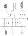
- FIG. 5is a sequence diagram for messages sent according to the medium access control (MAC) techniques described herein for the sensor node network shown in FIG. 3 .
- MACmedium access control
- FIG. 6Ais a flow diagram of a prior art wake-up routine.
- FIG. 6Bis a flow diagram of a power efficient wake-up routine.
- FIG. 7Ais a flow diagram of a prior art node synchronization routine.
- FIG. 7Bis a flow diagram of a power efficient node synchronization routine.
- FIG. 8Ais a flow diagram showing how a node with a dead battery affects other nodes in the network using prior art techniques.
- FIG. 8Bis a flow diagram showing how the MAC procedures described herein deal with a node having a dead battery.
- FIG. 9is a chart comparing wake-up latency of prior art MAC techniques with the MAC techniques described herein.
- FIG. 10is a chart comparing latency for a low battery node case for prior art MAC techniques with the MAC techniques described herein.
- FIG. 11is a chart comparing latency for a dead battery node case for prior art MAC techniques with the MAC techniques described herein.
- FIG. 12is a chart comparing synchronization time periods for prior art MAC techniques with the MAC techniques described herein.
- FIG. 1illustrates a wireless unmanned ground sensor (UGS) network 10 that is an example of the type of wireless sensor network in which the MAC techniques described herein may be useful.
- UGSunmanned ground sensor
- the unique system requirements of the UGS network 10affect virtually every aspect of its design; typically, routing and link layer protocols.
- the sensor derived datais forwarded to a Command & Control vehicle, called a C 2 node, for processing.
- Sensorsare deployed in the field in groups where sensors are located in proximity to each other.
- Sensors(referred to as P nodes) form a multi-hop network using short-range radios.
- Each sensor networkalso includes long-range-radio-equipped R (remote) nodes used to send sensor data back to the C 2 node.
- the C 2 nodeis assigned reference numeral 100
- the R nodesare assigned reference numeral 200 ( 1 ) to 200 (N)
- a P sensor fieldis assigned reference numeral 300 ( 1 ) to 300 (N)
- P sensorsare assigned reference numeral 400 ( 1 ) to 400 (N).
- the P node sensors 400 ( i )perform simple sensing tasks such as target detection, location, and simple target classification using acoustic, seismic, magnetic, and simple motion detection. Data from a number of P node sensors 400 ( i ) are transmitted to a central collection R node 200 ( i ).
- the R node 200 ( i ) associated with each P sensor field 300 ( i )gathers data from all of its subtending sensors (P nodes) and processes and fuses that data to remove redundant information and false alarms.
- the R node 200 ( i )may use locally attached sensors to further enhance the information that was received.
- Such a P nodewill be connected to an R node radio via an RS-232 link.
- the R node radioprovides the networking that forwards this data to the C 2 node 100 . If the distance between the C 2 node 100 and the nearest R node 200 ( i ) exceeds the maximum RF range, additional R nodes may be used as relays.
- All sensor nodesneed to coordinate their sleep schedules as opposed to doing so arbitrarily.
- All sensor nodesare assumed to have the same capabilities and can perform the same sensing and communication functions. This is based on the fairness in the contention-based random access schemes they employ.
- node densities, as well as RF rangesare drastically different from those of the conventional add-hoc wireless networks such as MANET systems.
- a nodewakes up periodically from its sleep state to listen if a neighbor want to contact it.
- a wakeup ACKis needed to switch to normal communications. This, again, consumes energy.
- Time synchronization in the conventional sensor networkrequires that a node synchronize to a faster node. Whenever, a faster node joins the network, the network must be re-synchronized and that consumes energy, unnecessarily.
- An R node 200( i ) comprises a general purpose processor (GPP) 210 and a digital signal processor (DSP) 220 .
- the GPP 210manages intranet layer functions 212 and some aspects of link layer (LL) functions 214 .
- the DSP 220manages link layer functions 222 , MAC functions 224 , late network entry (LNE) synchronization functions 226 and a wake-up circuit 228 that generates an RF wake-up signal.
- There is also a power monitor controller 230also called a sleep/wake-up controller that monitors power consumption and availability and is coupled to a radio transceiver 240 .
- the wake-up circuit 228can wake-up the DSP 220 from a sleep mode.
- the R nodes 200 ( i )When the R nodes 200 ( i ) are initially deployed, they will be configured by a relayer and enter a sleep state after their activity timers expire. They will take no further action until the C 2 node 100 has issued a network formation command. This feature prevents deployed sensors from becoming prematurely active and consequently depleting their batteries.
- the C 2 node 100In order to organize the UGS network, the C 2 node 100 issues a wakeup command, followed by a LNE message. The LNE message is used to establish time synchronization throughout the UGS network and to convey a limited amount of topology information.
- the C 2 node 100then issues an organization command, causing the R nodes 200 ( 1 ) to 200 (N) to exchange topology information with each other. If there is no data traffic to be sent and the activity timer is expired, the nodes will enter sleep mode to conserve battery power and start to monitor the wake-up channel, as shown in FIG. 3 .
- the design of the UGS networktakes advantage of the fact that P sensor nodes 300 ( 1 ) to 300 (N) do not move and, therefore, do not require frequent routing updates.
- the C 2 node 100is always either the source or the destination of all traffic and any node's configuration can be changed by a host command.
- the C 2 node 100can leave, join, and be configured any time during deployment.
- the R nodes 200 ( 1 ) to 200 (N)form a dynamic self-organizing RF intranet headed by the C 2 node 100 .
- the C 2 nodeprovides the RF timing for the UGS network and is the head of the connectivity tree of the RF network. The following features are part of the UGS network.
- the C 2 node 100manages network organization.
- the C 2 node 100has unlimited battery power.
- the UGS networkis an IP Subnet.
- the LNE messagecan carry net organization parameters.
- the DSP 220 in an R node 200 ( i )can wakeup from sleep in less than 150 ms, for example.
- the GPP 210 in an R node 200 ( i )can wakeup from sleep in less than 250 ms, relatively slower than the DSP 220 .
- the DSP 220 and GPP 210 in an R node 200 ( i )can wakeup each other.
- Sensor data trafficcan wakeup nodes towards the path to the C 2 node 100 ; but need not wakeup the entire network.
- the C 2 nodemay announce shut down of the UGS network.
- the R nodesare stationary.
- a Relay R node shown at reference numeral 200 ( 3 ) in FIG. 1can be added to extend the battery life of nodes in the UGS network.
- the bulk of the trafficis from R nodes 200 ( 1 ) to 200 (N) to the C 2 node 100 .
- This skewed traffic routewill significantly strain the energy resources of the R nodes near the C 2 node 100 , making that neighborhood more susceptible to energy depletion and failure.
- the C 2 node 100has unlimited energy while the relayer R nodes (e.g., R node 200 ( 3 )), which do not have sensors, are dedicated to forwarding the sensor data.
- R nodes 200 ( 1 ) to 200 (N)operate on a limited battery lifetime.
- energy efficient protocols at various levelsi.e. physical layer, link layer, network layer, etc.
- the medium access and neighbor discovery (part of link layer protocol) functionsare performed by the DSP 220 and by the link layer function 214 if the GPP 210 in the R nodes. Prudent MAC and neighbor discovery protocols are extremely critical for the energy-aware network design.
- the method of medium accessincludes a wake-up signal in case the destination is in sleep mode, Late Net Entry (LNE), if necessary for time synchronization, followed by the normal channel access procedures. The normal channel access is accomplished with the CSMA/CA algorithm.
- the wake-up circuit 228has a separate, ultra-low power receiver that listens for wake-up signals.
- the antenna inputis mechanically switched from the normal receiver 240 to the wake-up circuit 228 .
- a host wakeup messageis issued to wakeup the local node's DSP 220 and GPP 210 and be ready to form the network before data transmission.
- the C 2 node 100transmits the C 2 wakeup waveform, while R nodes 200 ( 1 ) to 200 (N) transmit the sensor wakeup or rebroadcast the C 2 wakeup waveform if the R nodes receive it.
- the awaken R nodetransmits the over-the-air (OTA) wakeup signal to its neighbor R nodes.
- OTAover-the-air
- the C 2 node 100issues the LNE message (also called the synchronization message) through a LNE channel to synchronize the UGS network and, then, data transmission takes place through the normal channel—in the “active” state.
- LNE messagealso called the synchronization message
- the link layer 214 managed by the GPP 210requests “Sleep Request” to the intranet. If the intranet is not busy, then, it agrees with the DSP to go to the sleep state by sending its response (“ready-to-sleep”). Once the “ready-to-sleep” response is received, the handshaking between DSP 220 and GPP 210 prior to going to sleep ensures that the DSP 220 goes to sleep after the GPP 210 does. If the intranet is busy, then the R node stays in the active state.
- Each R nodehas a real-time clock associated with its modem to drive RF communication. This clock can be synchronized to a variety of sources, modem or internal clock. An R node can optionally have a lower accuracy wake-up circuit clock, which is used to wakeup nodes from power-conserving sleep states.
- the LNE messageis transmitted on a frequency channel with CDMA spreading codes and TRANSEC based on an LNE period. Therefore, if the internal clocks of two nodes match each other within the coarse LNE period granularity, then either node will be able to hear the other's LNE message.
- the transmitted LNE signalcontains information that will allow the receiving node to synchronize its internal clock with that of the transmitting node to a finer level of granularity. Once time is synchronized between nodes, normal data exchange can take place between the two nodes. LNE operations are designed to permit rapid network formation, while ensuring minimum impact on network components that have already been formed. A node that has not yet discovered any RF Neighbors is called an “Isolated” node, whereas one with neighbors is called an “Associated” node. LNE transmissions for “Associated” nodes do not interfere with normal communication network and data traffic.
- the node that sends the LNE messagestamps the time at the MAC layer in the message just before putting the packet on the channel. This removes the send time and the access time from the critical path.
- the receiving noderecords the time of reception as soon as it starts receiving the packet. This removes the receive time from the critical path to achieve the tight time synchronization.
- a major function of the link layeris to collect neighbor information and form what is called a “neighbor table”.
- a neighbor tablecontains information on all RF neighbors known to the link layer 214 of the GPP 210 in an R node, regardless of link quality, is directly visible only to the GPP 210 and is updated each time a reception from a neighbor occurs.
- the DSP 220will attempt to exchange messages, called a Ping-RTS (PRTS) message, with each of the nodes entered in this table. The purpose of these messages is to verify the local nodes'ability to establish, and to maintain, a bi-directional data link with that node.
- PRTSPing-RTS
- the link layer function of the GPP 214is solely responsible for determining if a newly discovered node can be considered a viable RF Neighbor.
- the GPP 210is also the only processor that can totally delete a neighboring node.
- the typical timing sequence among these wake-up, LNE and neighbor discovery operationsis described by the event sequences shown in FIG. 5 .
- the C 2 nodewants to collect sensor information from the sensor fields it initiates the formation of the sensor network by transmitting a C 2 wake-up signal to wakeup the R nodes that are in sleep state, followed by transmission of an LNE message. Multiple C 2 wake-up signals can be sent to ensure many neighbors wakeup, prior to transmitting the LNE message.
- the C 2 nodeis considered in “Associated” mode initially.
- an “Isolated” node (R1)When an “Isolated” node (R1) hears the wake-up signal (if it is in sleep state), it wakes up its DSP and GPP, rebroadcasts the received C 2 wake-up message and sets its receiver to listen to the LNE channel in order to synchronize the local clock with the C 2 node's clock. Once the LNE message is received, then the “Isolated” node (R1) synchronizes its clock with the C 2 node's clock and transmits a PRTS (Ping-RTS) packet to the C 2 node. If a PRTS packet is received, the C 2 node finds it has a downstream node(s) and sends an acknowledgment (called PACK) back to the sender (R1).
- PACKacknowledgment
- the downstream node (R1)Upon receiving a PACK from the C 2 node, the downstream node (R1) becomes an “Associated” node and behaves like the upstream node. Now the R1 node transmits an LNE message periodically for other “Isolated” nodes (R2) to join the existing UGS network.
- the UGS networkstays in sleep state until the C 2 node initiates the network wakeup to collect the sensor information from the downstream nodes.
- the R nodewakes up the network when it is in sleep state and has data to send to the C 2 node.
- the activity timerrunning at each R node, is expired, the UGS network goes back to sleep state.
- An important aspect of the CSMA techniqueis a random back off timer that a node uses if it detects a busy medium. If the channel is in use, the node must wait a random period of time before attempting to access the medium again. This ensures that multiple nodes wanting to send data do not transmit at the same time.
- the random delaycauses nodes to wait different periods of time and avoids all of them sensing the medium at exactly the same time, finding the channel idle, transmitting, and colliding with each other.
- the back off timersignificantly reduces the number of collisions and corresponding retransmissions, especially when the number of active users increases.
- the typical random back-off time in the current designis uniformly distributed among nodes, which contend for access to the channel.
- the C 2 nodemay transmit multiple wakeup signals to make sure that if 1-hop away R nodes miss the first wakeup signal they receive the next one.
- the number of C 2 wake-up attempts(C 2 WuAttempts) is a configurable parameter and its interval (C 2 WuTxInterval) is of fixed duration to complete the wake-up RF transmission over the wake-up channel.
- C 2 WuTxIntervala configurable parameter and its interval to complete the wake-up RF transmission over the wake-up channel.
- the transmission duration (C 2 WuTxInterval) of a wakeup signal over the wakeup RF channelis generally much longer than those of the normal communication channel. Also, the value of WuTxRandomInterval is set rather large to avoid the collision of wakeup signals from neighbor(s). This large random back-off delay of wake-up signals in equation (1) causes the unnecessary time delay to wakeup the entire UGS network.
- a nodestops monitoring the wakeup channel and tunes to the LNE channel to receive the LNE messages in order to synchronize its clock with that of the C 2 node.
- the transmission of multiple wakeup signalsdoes not improve the probability of detection and false alarm with the conventional wakeup circuit. Rather, the C 2 node, which has unlimited battery life, transmits one wake-up signal immediately because no collision of wake-up signals occurs in the UGS network when the C 2 node initiates network formation.
- the wakeup signal, transmitted by the C 2 nodemay employ an increased process gain, if low probability of intercept and low probability of detection (LPI/LPD) is involved.
- Increased process gain of the wake-up signalmay be achieved by one or more of: a greater bandwidth, slower bit rate and higher chip rate (in the case of spread spectrum signals) in order to make the wake-up signal more likely to be detected by R nodes.
- the 7 R-node UGS network shown in FIG. 6Aillustrates the prior art approach of the wakeup waveform design. Assuming the R2 node is located between nodes R1 and R3 and is out of range of the C 2 node's transmit power, the R2 node must wait until the R1 or R3 node rebroadcasts the C 2 wakeup waveform. For example, using the conventional approach, when the C 2 node transmits the wakeup signal to form the UGS network, while the R1 and R3 are in the “Associated” status, they cannot rebroadcast the C 2 wakeup signal to the “Isolated” R2 node.
- a method of waking up nodes in a wireless communication networkcomprising: transmitting a single wake-up signal by a first node with at least one parameter that increases the range of the wake-up signal; receiving the wake-up signal from the first node at at least a second node, and in response thereto, the second node entering a wake-up state; and in response to the second node entering the wake-up state, rebroadcasting the wake-up signal to wake-up other nodes prior to the second node switching to a higher power consumption receiver to receive a synchronization message.
- the parameter used to transmit the single wake-up signalmay be one or more of a bit rate (lower bit rate), bandwidth, and chip rate (higher chip rate for spread spectrum modulation), that increases the processing gain of the wake-up signal.
- the wakeup signal, or symbolmay be composed of a pseudo-noise (PN) sequence to comply with LPD/LPI requirements, and also an anti-jamming (AJ) requirement.
- PNpseudo-noise
- the transmitterselects the PN sequence (S j ) at the beginning of the wakeup epoch (j) and transmits this wakeup signal at the selected channel (F j ). If a node's receiver clock differs around the epoch boundary from that of the transmitter, then the receiver misses the wakeup signal completely.
- the conventional approachtransmits the current PN sequence (S j ) at channel (F j ) followed by the next PN sequence (S j+1 ) at channel (F j+1 ).
- the receivercan receive either the S j or S j+1 signal. Again, this approach does not improve the probability of detection (P d ) or false alarm rate (P fa ).
- a better approachis to combine two PN sequences (S j and S j+1 ) into a single signal transmitted at channel (F j ).
- the single wake-up signalis formed by combining at least two PN sequences and transmitting the single wake-up signal at a frequency channel related a first of the PN sequences.
- the receivercan detect the S j or S j+1 signal, or both. This latter approach solves the boundary problem and improves the P d and P fa over the conventional one without degradation of AJ/LPI/LPD.
- a LNE messagecontains the following information: Sender's Local Clock, Source Node ID, C 2 node Address, Number of Hops To C 2 node, Battery Life Index and Cost To C 2 node.
- the neighbor discovery protocol(of the link layer) allows that the MAC protocol listens for LNE(s) in a pre-defined period (LneListenTime). After this timer is expired, the MAC protocol stops to monitor the LNE channel and begins to monitor the reservation channel for normal communication. The best LNE source based on the LNE information is selected and the inquiry process starts to find the best upstream node.
- the best upstream nodegenerates the more and faster LNE signals than the lesser nodes to enhance the probability of reception.
- the OTA transmitted by the LNE(s)is controlled by each node's status. This optimized LNE transmission produces the fast reception of the best LNE source.
- the LNE algorithmwaits for an LneXmtInterval interval to provide time during which external nodes may respond to the LNE message. This interval is randomized over a configurable time range of LneXmtInterval. This conventional time synchronization, equation (3), is not adequate to the UGS network because all nodes have an equal opportunity of medium access.
- an “Isolated” nodedoes not transmit the LNE message unless it achieves “Associated” status.
- the C 2 nodedeclares itself an “Associated” node and starts to transmit the LNE message to find if there is an R node in the UGS network.
- a node that is far from the C 2 nodemust wait a long time to receive the LNE message because the implementation of equation (3) assumes that all “Isolated” nodes have equal opportunity to synchronize with the “Associated” nodes.
- the unique application requirement of the UGS networkmust be built into the time synchronization process.
- the C 2 nodeleaves the network anytime and initiates to form the network anywhere, while the R nodes in the network are stationary. Also the C 2 node has no shortage of battery power and maintains the better communication link due to its better antenna exposure.
- the R nodeshave a limited battery life and may have connectivity impairments with each other in a tactical environment. This includes frequent network topology changes, network partitions, and radio characteristic changes (i.e., role, battery level, sleep or active state).
- the application requirementsare to be accounted for in the LNE transmission rate so that time synchronization is achieved as soon as possible in a UGS network.
- This optimized LNE transmission period of a given nodemakes the reception of LNE by an “Isolated” node faster and, therefore, consumes less energy.
- the C 2 nodetransmits the LNE periodically. Because the C 2 node initiates the LNE message in the UGS network, it transmits the first LNE message immediately without collision after waiting a very short time to transmit (C2WaitSetUpTime).
- the configurable time range of C 2 LneXmtIntervalis set much smaller than LneXmtInterval in equation (3) so that as many 1-hop away R nodes are synchronized with the C 2 node much faster.
- LneXmt TimeA 1 *Lne Hop Interval+ A 2 *BatteryLifeInterval+ A 3 *Lne CountInterval+random( LneXmt interval) (6)
- the first weighting factor (A 1 ) in equation (6)implies that R nodes, nearer to the C 2 node, generate more frequent LNE messages than R nodes that are farther away.
- the second (A 2 ) termguarantees that R nodes with stronger battery power generate more LNE messages so that those R nodes become the upstream nodes over those R nodes with relatively weaker battery power. For example, if a node has extremely low battery (or less than a remaining battery threshold), then it sets this weight factor very large so this node cannot be a LNE message source and avoids being an upstream R node.
- the sequence number of LNE message generated (A 3 )is included in the LNE period because the probability of LNE message being received by an “Isolated” node becomes less likely when the LNE message sequence number increases. An “Isolated” node generates far less or stops transmitting LNE messages when this sequence number is greater than the pre-defined threshold.
- These configurable weight factors (A 1 , A 2 , A 3 ) and their base-timers (LneHopInterval, BatteryLifeInterval, LneCountInterval, LneXmtInterval) in equation (6)must be optimized for the UGS network. The ideal time synchronization minimizes energy use by providing service that is exactly necessary and sufficient for the needs of the application.
- the configurable parameters in equation (6)can allow synchronization to be matched more closely to the requirements of the UGS application.
- the optimized LNE periodcan yield a faster time-synchronization than the conventional one shown in FIG. 7A .
- the conventional LNEis generated after each R node's wake-up in a uniformly distributed fashion.
- the first R1 node's LNE messageis received by R2 before R3's LNE message arrival to illustrate the improvement of the optimized approach shown in FIG. 7B .
- R1has lower battery power than R3.
- R2 nodeselects R3 node as the upstream node and attempts to form the bi-directional link (neighbor discovery).
- R3generates a faster LNE message than R1 does by the proposed formula and this prevents the weak node(s) from serving upstream transmissions.
- a method of synchronizing nodes in a communication networkcomprising adaptively selecting a transmission rate at which synchronization messages are to be transmitted from a synchronized node, the transmission rate being selected as a function of one or more factors including: a number of node hops between the synchronized node and a certain node; a remaining available power level of the synchronized node; and a number of synchronization message previously transmitted by the synchronized node in a current network synchronization sequence; and transmitting synchronization messages from the synchronized node to other nodes in the communication network according to the selected transmission rate.
- a particular nodeserves as an upstream node through which data from other nodes is transmitted for retransmission to the master node based on the one or more factors associated with the particular node.
- No neighbor discovery operationcan take place until the local node has completed its time synchronization operation via the LNE process. Once the node has completed time synchronization, it will begin to issue PRTS messages in order to identify those RF neighbors with which successful bi-directional communication can be established.
- FIG. 5shows the flow of a PRTS message in order to find the RF neighbor.
- the LLdelays for a random time interval and sends the PRTS message as broadcast over the reservation channel.
- the transmit interval of PRTS(PrtsXmtTime) is randomized by
- PrtsXmt Timerandom( PrtsXmt Interval) (7)
- PrtsXmt TimePrts ResponseInterval+random( PrtsXmt Interval) (8)
- the LLwaits a PrtsResponseInterval interval in order to provide time during which remote nodes may respond to the PRTS. This interval is randomized over a configurable time range of PrtsXmtInterval.
- an “Associated” nodeor upstream node
- receives the PRTS messageit knows that there are downstream node(s) to join the network. It sends an acknowledgement called a PACK.
- PACKacknowledgement
- an “Isolated” nodebecomes an “Associated” one, terminating the PRPS process and starting to transmit the LNE message periodically. If no PACK is received from the upstream node and the PrtsXmtTime timer expires, a new PRTS message is issued until NumberPrtsTries have been issued.
- the local nodethen ceases to issue PRTSs until PROPHoldOff seconds have elapsed and then declares the node as still being “Isolated”—LNE failure. Then, the LL protocol is waiting for the next command from the intranet.
- the application requirements of the UGS networkapply, also, to the generation of the PRTS messages. Because the PRTS message(s) are broadcasted in the reservation channel, the 1-hop away nodes can hear other PRTS messages generated by the neighbor(s). A node with the stronger battery life is preferred to request the PRTS to the upstream node. That is, the node with stronger battery life has priority over those with weaker battery life.
- PrtsXmt TimePrts ResponseInterval+random( PrtsXmt Interval) (10)
- a method of performing discovery of nodes in a wireless communication network in order for two nodes to have bi-directional communicationcomprising determining a level of remaining available power at a node in the wireless communication network; selecting a transmission rate at which to transmit node discovery messages from the node as a function of the level of remaining available power; and transmitting node discovery messages from the node according to the selected transmission rate.
- the node discovery messagemay be a RTS message that is intended to solicit and acknowledgment message from a node that receives it.
- a nodereceives the node discovery message from another node, it knows that the node that transmitted the node discovery message is a downstream node that wishes to join the wireless network.
- the node that transmitted the node discovery messagereceives the acknowledgment message, it joins the wireless network by transmitting a synchronization message to other nodes in the network.
- the typical 7-nodes scenariois selected to illustrate the performance analysis.
- the 7-node UGS networkis in the sleep state at the beginning and the C 2 node commands the network formation: (1) the C 2 node transmits the C 2 wakeup signal, (2) followed by the LNE for time synchronization and (3) PRTS query process to form a bi-directional link.
- the reception of a PACKis not included in the latency computation because its delay is negligible.
- the latencyis defined by how long time it takes for an “Isolated” node to become an “Associated one”.
- the goal of this analysisis to determine: (1) how fast the UGS network is formed after being initiated by the C 2 node and (2) minimize the number of OTA message transmission.
- node R1receives the wakeup signal from the C 2 node, which it rebroadcasts to nodes R2 and R4. More bits in the wakeup signal from the C 2 node increase the process gain (PG), thereby increasing the probability to reach node R2.
- PGprocess gain
- two conventional C 2 bit patternsmay be combined to make the C 2 waveform (1024 bits) and the wakeup detector is integrated and summed to improve the full process gain of 3 dB.
- node R2After node R2 is awake, it switches the antenna to listen to any LNE message as shown in FIG. 8B .
- the received LNE(s) at node R2could be generated from nodes R1 or R3.
- the improved MAC protocoldetermines the desirable node, in terms of the energy usage, to be the upstream node.
- node R2selects node R3 (which has strong battery power) as the upstream node, as shown in FIG. 8B .
- Exemplary values for C 2 WuAttemps and LneXmtIntervalare 2 and 3 seconds, respectively.
- R3generates the LNE message faster than R1 so that R2 synchronizes with R3, while with the conventional approach R2 synchronizes with R1.
- R2 nodeselects R3 node (which has strong battery power) as the upstream node.
- R1is the only one “Isolated”, while nodes R 4 and R 6 are still attached to R2, as shown in FIG. 8B .
- the UGS network with the conventional approachmay or may not achieve the same topology as would be achieved with the improved MAC protocol.
- the C 2 node wakeup bit-pattern(512 bits) is transmitted twice (at 40 Kbps) for the conventional protocol and the proposed C 2 wakeup (1024 bits) is transmitted (also, at 40 Kbps) immediately after the identical transmitter set-up time delay.
- the transmitter set-up timeis 12 msec and the random delay WuRandomInterval is 2 seconds for both protocols.
- FIG. 9presents the latency comparison between the conventional MAC protocol and the improved MAC protocol, assuming that only the improved C 2 wakeup signal is applied and the LNE and PRTS algorithms are the same for both.
- the latencyis shortened by 1.1 seconds and this is propagated throughout the UGS network.
- the multiple-C2-wakeup-signal transmissiondoes not improve the probability of detection and false alarm rate.
- the improved PG C 2 transmissionis more desirable because it reaches farther nodes and does not degrade the LPI/LPD feature.
- the LneXmtInterval (3 seconds) in the conventional LNEis distributed equally (1 second each) among the three intervals in the improved MAC LNE equation (6) (LneHopInterval, BatteryLifeInterval and LneCountInterval).
- FIGS. 10 and 11present the latency comparison for the R1 node low battery and dead battery cases.
- Node R1's battery indexis set to 5 (low battery case) and 0 (dead case) and node R3's is set to 15 (maximum index), while others are set to 10.
- FIG. 10presents the latency of the conventional protocol against that of the improved MAC protocol.
- Nodes R4 and R6 in the conventional caseare “Isolated”, but, they are downstream nodes in the Opt-MAC protocol case, as expected.
- the overall performance of the improved MACis superior to that of the conventional approach.
- FIG. 12presents the LNE message transmit period for nth messages.
- the conventional LNE messageis transmitted every 3 seconds continuously, while the improved MAC transmits the LNE message slower when the LNE message sequence increases.
- the first two LNE messagesare transmitted much faster than in the conventional approach and the later LNE messages are generated at a much slower rate.
- One unique aspectis controlling the LNE message transmit time at any rate while not degrading the latency. For example, when a node is very low in battery power, it stops transmitting its LNE message to avoid being the upstream node. If the first several LNE messages can not be received by the “Isolated” nodes, then it is a waste of energy to keep transmitting the LNE in the UGS network. When a network is needed to form or re-form, the C 2 node initiates the wakeup procedure and commands the network formation. Then the “Isolated” nodes, which could not connect to the network, can then join the network.
- an application requirements-based energy-efficient MAC protocolis provided. Unlike conventional MAC protocols that treat all nodes equally with respect to energy conservation, the MAC protocol described herein is based on the critical UGS application requirements of sensor nodes.
- the application requirements of a sensor nodecould be based purely on local node information, such as number of hops to the C 2 node, relative current battery life level, and LNE message sequence number. Because the UGS network is formed during the first few LNE messages, the LNE message sequence number is included in the formula to control unnecessary OTA transmission.
- the “Isolated” node with the best LNE s message source within the neighborhooddeclares itself as soon as possible as the next “Associated” node at the end of RF neighbor discovery.
- the advantage behind this approachis the reduction of the idle listening time thereby reducing energy of the critical “Isolated” nodes in the process of transitioning to the “Associated” status. Thus, nodes can go to sleep fast when they have nothing to transmit.
- the MAC protocolhas been described herein for reduction of the idle time and the OTA traffic of a UGS network, but it should be understood that it is also applicable to other sensor networks that employ a tree-like topology. For example, it is applicable to a military or civilian ad-hoc sensor networks in general or any sensor network involving airborne, ship-based, as well as mixed ground-based/airborne/ship-based network configurations.
Landscapes
- Engineering & Computer Science (AREA)
- Computer Networks & Wireless Communication (AREA)
- Signal Processing (AREA)
- Mobile Radio Communication Systems (AREA)
- Arrangements For Transmission Of Measured Signals (AREA)
Abstract
Description
WuTxTime=C2WuAttemps*C2WuTxInterval+Random(WuTxRandomInterval) (1)
WuTxTime=C2WuTxInterval+Random(WuTxRandomInterval) (2)
NumHopsToC2*{C2WuAttemps*C2WuTxInterval+Random(WuTxRandomInterval)} (3)
LneXmtTime=0.5*LneXmtInterval+Random(LneXmtInterval) (3)
C2LneXmtTime=C2WaitSetUpTime (4)
C2LneXmtTime=C2LneXmtInterval+Random(C2LneXmtInterval) (5)
LneXmtTime=A1*LneHop Interval+A2*BatteryLifeInterval+A3*LneCountInterval+random(LneXmtinterval) (6)
- A2=remaining battery/maximum battery
- A3=LNE message count starting from 0.
PrtsXmtTime=random(PrtsXmtInterval) (7)
PrtsXmtTime=PrtsResponseInterval+random(PrtsXmtInterval) (8)
PrtsXmTimel=A1*BatteryLifeInterval+random(PrtsXmtInterval) (9)
PrtsXmtTime=PrtsResponseInterval+random(PrtsXmtInterval) (10)
LneXmtTime={number-of-hops-to-C2/MaximumHops}*LneHopInterval+{MaximumBatteryIndex/local-battery-index}*BatteryLifeInterval+lne-pkt-count*LneCountInterval+random(LneXmtInterval) (6)
where
Claims (19)
Priority Applications (2)
| Application Number | Priority Date | Filing Date | Title |
|---|---|---|---|
| US11/007,259US7496059B2 (en) | 2004-12-09 | 2004-12-09 | Energy-efficient medium access control protocol and system for sensor networks |
| GB0523434AGB2421153B (en) | 2004-12-09 | 2005-11-17 | Energy-efficient medium access control protocol and system for sensor networks |
Applications Claiming Priority (1)
| Application Number | Priority Date | Filing Date | Title |
|---|---|---|---|
| US11/007,259US7496059B2 (en) | 2004-12-09 | 2004-12-09 | Energy-efficient medium access control protocol and system for sensor networks |
Publications (2)
| Publication Number | Publication Date |
|---|---|
| US20060128349A1 US20060128349A1 (en) | 2006-06-15 |
| US7496059B2true US7496059B2 (en) | 2009-02-24 |
Family
ID=35580224
Family Applications (1)
| Application Number | Title | Priority Date | Filing Date |
|---|---|---|---|
| US11/007,259Active2026-06-07US7496059B2 (en) | 2004-12-09 | 2004-12-09 | Energy-efficient medium access control protocol and system for sensor networks |
Country Status (2)
| Country | Link |
|---|---|
| US (1) | US7496059B2 (en) |
| GB (1) | GB2421153B (en) |
Cited By (41)
| Publication number | Priority date | Publication date | Assignee | Title |
|---|---|---|---|---|
| US20070066311A1 (en)* | 2005-09-22 | 2007-03-22 | Jean-Michel Reibel | Spread spectrum wireless communication and monitoring arrangement and method |
| US20070076747A1 (en)* | 2005-09-30 | 2007-04-05 | Amir Zinaty | Periodic network controller power-down |
| US20070165545A1 (en)* | 2006-01-11 | 2007-07-19 | Fisher-Rosemount Systems, Inc. | Control of low power wireless networks for power conservation |
| US20080137620A1 (en)* | 2006-12-07 | 2008-06-12 | Kiyon, Inc. | System and Method for Timeslot and Channel Allocation |
| US20090010189A1 (en)* | 2007-07-07 | 2009-01-08 | Nagra Sundeep S | Network with remaining battery life routing metric |
| US20090047927A1 (en)* | 2005-12-14 | 2009-02-19 | Christoph Weiler | Method for Operating a Radio Network and Subscriber Device for Said Type of Network |
| US20090201840A1 (en)* | 2008-02-08 | 2009-08-13 | Pfeiffer Jr Loren K | Wireless networks using a rooted, directed topology |
| US20090316679A1 (en)* | 2008-06-23 | 2009-12-24 | Frits Van Der Wateren | Broadcast-only distributed wireless network |
| US20100008275A1 (en)* | 2006-09-29 | 2010-01-14 | Lee In-Hwan | Node synchronization system for low-power in sensor network and method thereof |
| US20100074157A1 (en)* | 2006-12-08 | 2010-03-25 | Electronics And Telecommunications Research Institute | Sensor node of wireless sensor networks and operating method thereof |
| US20100098102A1 (en)* | 2008-10-16 | 2010-04-22 | Kevin Banks | Systems and methods for reducing power consumption in communication networks |
| US20100135263A1 (en)* | 2008-06-03 | 2010-06-03 | Radoslaw Romuald Zakrzewski | Wireless sensor system |
| US7941149B2 (en) | 2002-05-13 | 2011-05-10 | Misonimo Chi Acquistion L.L.C. | Multi-hop ultra wide band wireless network communication |
| US7957356B2 (en) | 2002-05-13 | 2011-06-07 | Misomino Chi Acquisitions L.L.C. | Scalable media access control for multi-hop high bandwidth communications |
| US20120008626A1 (en)* | 2008-06-23 | 2012-01-12 | Greenpeak Technologies N.V. | End node and network coordinator using a csma based protocol |
| US8144622B2 (en) | 2003-06-18 | 2012-03-27 | Fisher-Rosemount Systems, Inc. | Wireless architecture and support for process control systems |
| US8160574B1 (en)* | 2005-06-17 | 2012-04-17 | Fisher-Rosemount Systems, Inc. | Wireless architecture utilizing geo-referencing |
| US8175613B2 (en) | 2006-08-04 | 2012-05-08 | Misonimo Chi Acquisitions L.L.C. | Systems and methods for determining location of devices within a wireless network |
| US20120166848A1 (en)* | 2005-03-30 | 2012-06-28 | Alan Broad | Adaptive network and method |
| TWI384792B (en)* | 2009-06-23 | 2013-02-01 | Univ Nat Taiwan | Reporting method for a data transmission device and computer readable medium thereof |
| US8384590B2 (en) | 2010-08-27 | 2013-02-26 | National Taiwan University | System and method for time synchronization |
| US8406217B2 (en) | 2010-04-16 | 2013-03-26 | Simmonds Precision Products, Inc. | Synchronizing wireless devices using timestamps and relative clock offsets of the wireless devices |
| US20130100942A1 (en)* | 2011-10-24 | 2013-04-25 | Harris Corporation | Mobile ad hoc network with dynamic tdma slot assignments and related methods |
| US20130246551A1 (en)* | 2012-03-13 | 2013-09-19 | Gun-Woo Park | Apparatus and method for time synchronization by automatically controlling sending message count of master |
| US8780770B2 (en) | 2002-05-13 | 2014-07-15 | Misonimo Chi Acquisition L.L.C. | Systems and methods for voice and video communication over a wireless network |
| US8953547B2 (en) | 2013-03-29 | 2015-02-10 | Olympus Corporation | Power-saving TDMA MAC for wireless body area networks |
| US9007231B2 (en) | 2013-01-17 | 2015-04-14 | Baker Hughes Incorporated | Synchronization of distributed measurements in a borehole |
| US9119185B2 (en) | 2013-03-29 | 2015-08-25 | Olympus Corporation | Power-saving hub messages in wireless body area networks |
| US20160219348A1 (en)* | 2013-09-10 | 2016-07-28 | Telefonaktiebolaget Lm Ericsson (Publ) | Method and Monitoring Centre for Supporting Supervision of Events |
| US9503974B1 (en)* | 2008-09-23 | 2016-11-22 | Synapse Wireless, Inc. | Systems and methods for operating a device in sleep and awake modes |
| US9504388B2 (en)* | 2010-03-15 | 2016-11-29 | Welch Allyn, Inc. | Personal area network pairing |
| US10104616B2 (en) | 2015-06-22 | 2018-10-16 | Qualcomm Incorporated | Downlink multiplexing and MAC signaling for a system with devices operating with and without low power companion receivers |
| US20180349157A1 (en)* | 2017-06-06 | 2018-12-06 | GM Global Technology Operations LLC | Processor-implemented systems and methods for vehicle updating over-the-air |
| US20190132796A1 (en)* | 2018-01-29 | 2019-05-02 | Po-Kai Huang | Wake-up frame indication |
| DE102015101699B4 (en)* | 2014-02-25 | 2019-12-24 | Qualcomm Technologies International, Ltd. | Processing mesh communications |
| US10536526B2 (en) | 2014-06-25 | 2020-01-14 | Honeywell International Inc. | Apparatus and method for virtualizing a connection to a node in an industrial control and automation system |
| US10587471B1 (en)* | 2013-12-17 | 2020-03-10 | Amazon Technologies, Inc. | Criterion-based computing instance activation |
| US10743307B2 (en) | 2014-12-12 | 2020-08-11 | Qualcomm Incorporated | Traffic advertisement in neighbor aware network (NAN) data path |
| US10820314B2 (en) | 2014-12-12 | 2020-10-27 | Qualcomm Incorporated | Traffic advertisement in neighbor aware network (NAN) data path |
| US11811642B2 (en) | 2018-07-27 | 2023-11-07 | GoTenna, Inc. | Vine™: zero-control routing using data packet inspection for wireless mesh networks |
| US12381802B2 (en) | 2022-12-16 | 2025-08-05 | Rockwell Collins, Inc. | System and method for deadzone routing of directional communications |
Families Citing this family (106)
| Publication number | Priority date | Publication date | Assignee | Title |
|---|---|---|---|---|
| US8050625B2 (en)* | 2000-12-22 | 2011-11-01 | Terahop Networks, Inc. | Wireless reader tags (WRTs) with sensor components in asset monitoring and tracking systems |
| US8175016B1 (en)* | 2004-03-19 | 2012-05-08 | Verizon Corporate Services Group Inc. | Systems, methods and computer readable media for energy conservation in sensor networks |
| US11733958B2 (en)* | 2005-05-05 | 2023-08-22 | Iii Holdings 1, Llc | Wireless mesh-enabled system, host device, and method for use therewith |
| WO2007100343A1 (en)* | 2005-06-03 | 2007-09-07 | Terahop Networks Inc. | Remote sensor interface (rsi) stepped wake-up sequence |
| KR100736044B1 (en)* | 2005-09-01 | 2007-07-06 | 삼성전자주식회사 | Power control method and apparatus of a wireless device |
| KR100683848B1 (en)* | 2005-10-11 | 2007-02-16 | 삼성전자주식회사 | Sensor Power Consumption Reduction Method and System for Wireless Sensor Network Based on Context Information |
| US7447526B2 (en)* | 2005-10-28 | 2008-11-04 | Samsung Electronics Co., Ltd. | Power-saving method for wireless sensor network |
| US8483616B1 (en) | 2005-11-01 | 2013-07-09 | At&T Intellectual Property Ii, L.P. | Non-interference technique for spatially aware mobile ad hoc networking |
| US8125964B2 (en)* | 2005-11-18 | 2012-02-28 | Telcordia Licensing Company, Llc | Framework for hybrid ad-hoc networks |
| US8149801B2 (en)* | 2007-08-17 | 2012-04-03 | At&T Intellectual Property Ii, L.P. | System and method for geocasting in a mobile ad hoc network |
| US8777752B2 (en) | 2005-11-30 | 2014-07-15 | At&T Intellectual Property I, L.P. | Geogame for mobile device |
| US8702506B2 (en)* | 2005-11-30 | 2014-04-22 | At&T Intellectual Property I, L.P. | Geogame for mobile device |
| US7969914B1 (en)* | 2008-07-25 | 2011-06-28 | At&T Intellectual Property Ii, L.P. | Method for establishing and operating a mobile Ad-Hoc network |
| US8355410B2 (en) | 2007-08-17 | 2013-01-15 | At&T Intellectual Property I, L.P. | Location-based mobile gaming application and method for implementing the same using a scalable tiered geocast protocol |
| US7525933B1 (en)* | 2005-11-30 | 2009-04-28 | At&T Intellectual Property Ii, L.P. | System and method for mobile ad hoc network |
| GB0616476D0 (en)* | 2006-08-18 | 2006-09-27 | Fujitsu Ltd | Communication systems |
| US7949747B1 (en)* | 2006-08-18 | 2011-05-24 | Ecowater Systems Llc | Method and system of communication in a wireless water treatment system |
| US20080049700A1 (en)* | 2006-08-25 | 2008-02-28 | Shah Rahul C | Reduced power network association in a wireless sensor network |
| US20080084836A1 (en)* | 2006-10-04 | 2008-04-10 | Bluewave Security, Inc. | Low power wireless communication method |
| CN101523829A (en) | 2006-10-12 | 2009-09-02 | 皇家飞利浦电子股份有限公司 | Method and system for time synchronization in a sensor network |
| US7715887B2 (en) | 2006-11-14 | 2010-05-11 | Harris Corporation | Low power distribution system for an unattended ground sensor system |
| EP1933507A1 (en)* | 2006-12-15 | 2008-06-18 | Ubiwave | Low-power multi-hop networks |
| KR100810661B1 (en)* | 2007-02-07 | 2008-03-07 | 삼성전자주식회사 | Radio resource allocation method and device therefor in wireless sensor network |
| US7991992B2 (en) | 2007-03-13 | 2011-08-02 | Intel Corporation | Power reduction for system on chip |
| US20090080442A1 (en)* | 2007-09-26 | 2009-03-26 | Narayan Ananth S | Conserving power in a multi-node environment |
| KR100893041B1 (en) | 2007-09-27 | 2009-04-15 | 주식회사 케이티 | Adaptive Wireless Link Access Control Method of Sensor Network Node |
| KR100932920B1 (en)* | 2007-12-17 | 2009-12-21 | 한국전자통신연구원 | Sensor node wake-up device and method |
| US20090207769A1 (en)* | 2008-01-14 | 2009-08-20 | Electronics And Telecommunications Research Institute | Method and apparatus for scheduling timing for communication between sensor nodes in wireless sensor network |
| JP5183228B2 (en)* | 2008-01-30 | 2013-04-17 | ラピスセミコンダクタ株式会社 | Multi-hop wireless communication system |
| KR20090090461A (en)* | 2008-02-21 | 2009-08-26 | 삼성전자주식회사 | How to extend the life of sensor node in wireless sensor network and system for it |
| US8189494B2 (en)* | 2008-05-23 | 2012-05-29 | Honeywell International Inc. | System and method for merging clusters of wireless nodes in a wireless network |
| US20100034183A1 (en)* | 2008-08-05 | 2010-02-11 | Broadcom Corporation | Flexible WLAN/WPAN system with high throughput |
| EP2319269B1 (en)* | 2008-08-27 | 2014-05-07 | Telefonaktiebolaget L M Ericsson (publ) | Routing mechanism for distributed hash table based overlay networks |
| WO2010028181A1 (en)* | 2008-09-03 | 2010-03-11 | Snif Labs | Activity state classification |
| US9544922B2 (en) | 2008-09-16 | 2017-01-10 | At&T Intellectual Property I, L.P. | Quality of service scheme for collision-based wireless networks |
| US8670435B2 (en) | 2009-01-30 | 2014-03-11 | Texas Instruments Incorporated | Access and power management for centralized networks |
| US8102271B2 (en)* | 2009-02-10 | 2012-01-24 | Electronics And Telecommunications Research Institute | Apparatus and method for asset tracking based on ubiquitous sensor network using motion sensing |
| KR101275469B1 (en)* | 2009-02-13 | 2013-06-17 | 미쓰비시덴키 가부시키가이샤 | Communication apparatus, communication system and slave station apparatus |
| US20110299472A1 (en)* | 2009-02-23 | 2011-12-08 | Praveen Kumar | Adaptive Synchronization scheme for wireless communication systems |
| US8824449B2 (en)* | 2009-03-05 | 2014-09-02 | Chess Et International Bv | Synchronization of broadcast-only wireless networks |
| US8837354B2 (en) | 2009-04-24 | 2014-09-16 | Honeywell International Inc. | Apparatus and method for supporting wireless actuators and other devices in process control systems |
| EP2476281A4 (en)* | 2009-09-10 | 2013-06-05 | Nokia Corp | RADIO COMMUNICATION |
| US9118428B2 (en) | 2009-11-04 | 2015-08-25 | At&T Intellectual Property I, L.P. | Geographic advertising using a scalable wireless geocast protocol |
| US8712056B2 (en) | 2010-06-03 | 2014-04-29 | At&T Intellectual Property I, L.P. | Secure mobile ad hoc network |
| US8498201B2 (en) | 2010-08-26 | 2013-07-30 | Honeywell International Inc. | Apparatus and method for improving the reliability of industrial wireless networks that experience outages in backbone connectivity |
| US10016684B2 (en)* | 2010-10-28 | 2018-07-10 | At&T Intellectual Property I, L.P. | Secure geographic based gaming |
| US8924498B2 (en) | 2010-11-09 | 2014-12-30 | Honeywell International Inc. | Method and system for process control network migration |
| EP2482596B1 (en) | 2011-01-26 | 2013-09-04 | Nxp B.V. | Syncronizing wireless devices |
| KR101268009B1 (en)* | 2011-02-22 | 2013-05-27 | 서울대학교산학협력단 | System and method for self-organization of wireless sensor networks |
| WO2012175104A1 (en)* | 2011-06-20 | 2012-12-27 | Siemens Aktiengesellschaft | Apparatus and method for sending and receiving radio signals |
| US9161158B2 (en) | 2011-06-27 | 2015-10-13 | At&T Intellectual Property I, L.P. | Information acquisition using a scalable wireless geocast protocol |
| US9319842B2 (en) | 2011-06-27 | 2016-04-19 | At&T Intellectual Property I, L.P. | Mobile device configured point and shoot type weapon |
| US9049660B2 (en)* | 2011-09-09 | 2015-06-02 | Microsoft Technology Licensing, Llc | Wake pattern management |
| US8806250B2 (en) | 2011-09-09 | 2014-08-12 | Microsoft Corporation | Operating system management of network interface devices |
| US8892710B2 (en) | 2011-09-09 | 2014-11-18 | Microsoft Corporation | Keep alive management |
| US8774056B2 (en)* | 2011-09-28 | 2014-07-08 | Schneider Electric USA, Inc. | Automated device discovery on a network |
| US9495870B2 (en) | 2011-10-20 | 2016-11-15 | At&T Intellectual Property I, L.P. | Vehicular communications using a scalable ad hoc geographic routing protocol |
| GB2496384B (en) | 2011-11-07 | 2014-06-25 | Broadcom Corp | Method and apparatus for controlling wireless devices |
| US8744419B2 (en) | 2011-12-15 | 2014-06-03 | At&T Intellectual Property, I, L.P. | Media distribution via a scalable ad hoc geographic protocol |
| US9367360B2 (en) | 2012-01-30 | 2016-06-14 | Microsoft Technology Licensing, Llc | Deploying a hardware inventory as a cloud-computing stamp |
| US9137111B2 (en) | 2012-01-30 | 2015-09-15 | Microsoft Technology Licensing, Llc | Discovering, validating, and configuring hardware-inventory components |
| US9641394B2 (en) | 2012-01-30 | 2017-05-02 | Microsoft Technology Licensing, Llc | Automated build-out of a cloud-computing stamp |
| US9917736B2 (en) | 2012-01-30 | 2018-03-13 | Microsoft Technology Licensing, Llc | Automated standalone bootstrapping of hardware inventory |
| US9191442B2 (en) | 2012-04-03 | 2015-11-17 | Accenture Global Services Limited | Adaptive sensor data selection and sampling based on current and future context |
| GB2502576B (en)* | 2012-05-31 | 2014-11-12 | Canon Kk | Method, device, computer program and information storage means for optimizing access to a wireless medium in a communication network |
| GB2502581B (en)* | 2012-05-31 | 2014-04-16 | Broadcom Corp | Method, apparatus and computer program for communicating |
| US10120725B2 (en) | 2012-06-22 | 2018-11-06 | Microsoft Technology Licensing, Llc | Establishing an initial configuration of a hardware inventory |
| US9071451B2 (en) | 2012-07-31 | 2015-06-30 | At&T Intellectual Property I, L.P. | Geocast-based situation awareness |
| US9585091B2 (en)* | 2012-08-17 | 2017-02-28 | Qualcomm Incorporated | Systems and methods for low power wake up signal and operations for WLAN |
| US9210589B2 (en) | 2012-10-09 | 2015-12-08 | At&T Intellectual Property I, L.P. | Geocast protocol for wireless sensor network |
| US9241307B2 (en)* | 2012-10-24 | 2016-01-19 | Qualcomm Incorporated | Method and apparatus using an ultra low power signal with scheduled power save modes |
| US9191890B2 (en) | 2012-10-24 | 2015-11-17 | Qualcomm Incorporated | Systems and methods for low power operations on wireless networks |
| US9191891B2 (en) | 2012-11-02 | 2015-11-17 | Qualcomm Incorporated | Systems and methods for low power wake-up signal implementation and operations for WLAN |
| US9660745B2 (en) | 2012-12-12 | 2017-05-23 | At&T Intellectual Property I, L.P. | Geocast-based file transfer |
| US10412783B2 (en) | 2013-03-14 | 2019-09-10 | Honeywell International Inc. | Shadow access point for hierarchical tree network using 802.11 infrastructure nodes in fire detection systems and other systems |
| US9992021B1 (en) | 2013-03-14 | 2018-06-05 | GoTenna, Inc. | System and method for private and point-to-point communication between computing devices |
| US9380638B2 (en) | 2013-03-14 | 2016-06-28 | Honeywell International Inc. | Hierarchical tree network using TDMA protocol with 802.11 infrastructure nodes for fire detection systems and other systems |
| US10292103B2 (en)* | 2013-03-27 | 2019-05-14 | Qualcomm Incorporated | Systems and methods for synchronization within a neighborhood aware network |
| US9110838B2 (en) | 2013-07-31 | 2015-08-18 | Honeywell International Inc. | Apparatus and method for synchronizing dynamic process data across redundant input/output modules |
| FR3014633B1 (en)* | 2013-12-11 | 2017-02-24 | Commissariat Energie Atomique | DEPLOYMENT OF AD HOC NETWORKS |
| US9236909B2 (en)* | 2013-12-19 | 2016-01-12 | Stmicroelectronics, Inc. | Zero standby power for powerline communication devices |
| US20170105176A1 (en)* | 2014-02-08 | 2017-04-13 | Switchmate Home Llc | Home automation ecosystem devices and power management |
| US9720404B2 (en) | 2014-05-05 | 2017-08-01 | Honeywell International Inc. | Gateway offering logical model mapped to independent underlying networks |
| US9906614B2 (en)* | 2014-05-05 | 2018-02-27 | Adobe Systems Incorporated | Real-time content sharing between browsers |
| US10042330B2 (en) | 2014-05-07 | 2018-08-07 | Honeywell International Inc. | Redundant process controllers for segregated supervisory and industrial control networks |
| US9699022B2 (en) | 2014-08-01 | 2017-07-04 | Honeywell International Inc. | System and method for controller redundancy and controller network redundancy with ethernet/IP I/O |
| US10148485B2 (en) | 2014-09-03 | 2018-12-04 | Honeywell International Inc. | Apparatus and method for on-process migration of industrial control and automation system across disparate network types |
| US9801129B2 (en)* | 2014-09-05 | 2017-10-24 | Google Inc. | Systems and methods for disseminating messages among a fabric network |
| US9801126B2 (en)* | 2014-10-28 | 2017-10-24 | Alcatel Lucent | Configurable communication modules for flexible communications within an energy-limited wireless system |
| US10162827B2 (en) | 2015-04-08 | 2018-12-25 | Honeywell International Inc. | Method and system for distributed control system (DCS) process data cloning and migration through secured file system |
| US10409270B2 (en) | 2015-04-09 | 2019-09-10 | Honeywell International Inc. | Methods for on-process migration from one type of process control device to different type of process control device |
| US9652963B2 (en)* | 2015-07-29 | 2017-05-16 | Dell Products, Lp | Provisioning and managing autonomous sensors |
| US10671428B2 (en)* | 2015-09-08 | 2020-06-02 | Apple Inc. | Distributed personal assistant |
| US11170616B2 (en) | 2016-03-16 | 2021-11-09 | Triax Technologies, Inc. | System and interfaces for managing workplace events |
| US10769562B2 (en) | 2016-03-16 | 2020-09-08 | Triax Technologies, Inc. | Sensor based system and method for authorizing operation of worksite equipment using a locally stored access control list |
| US10692024B2 (en)* | 2016-03-16 | 2020-06-23 | Triax Technologies, Inc. | Wireless mesh network system for monitoring worksite events including detecting false events |
| US11810032B2 (en) | 2016-03-16 | 2023-11-07 | Triax Technologies, Inc. | Systems and methods for low-energy wireless applications using networked wearable sensors |
| US10244480B2 (en)* | 2016-08-12 | 2019-03-26 | Gainspan Corporation | Wireless station relying on hibernation for power savings in a wireless local area network |
| US10296482B2 (en) | 2017-03-07 | 2019-05-21 | Honeywell International Inc. | System and method for flexible connection of redundant input-output modules or other devices |
| WO2018182131A1 (en)* | 2017-03-30 | 2018-10-04 | 엘지전자 주식회사 | Method for transmitting packet in wireless lan system and wireless terminal using same |
| US10401816B2 (en) | 2017-07-20 | 2019-09-03 | Honeywell International Inc. | Legacy control functions in newgen controllers alongside newgen control functions |
| US11310741B2 (en)* | 2017-08-18 | 2022-04-19 | Sony Group Corporation | Wake-up signal related monitoring of wireless data communication |
| CN109548121B (en)* | 2017-09-22 | 2022-03-18 | 珠海市魅族科技有限公司 | Communication method and device of wireless local area network, access point equipment and site equipment |
| US10805262B1 (en) | 2019-06-10 | 2020-10-13 | Banner Engineering Corp. | Modbus system having actual and virtual slave addresses and slave sensors |
| CN111542015B (en)* | 2020-05-11 | 2022-03-15 | 国网陕西省电力公司电力科学研究院 | MAC protocol method applied to transformer substation wireless sensor network and implementation system thereof |
| CN114938511B (en)* | 2022-05-07 | 2023-07-28 | 河海大学常州校区 | Self-adaptive directional neighbor discovery method based on reinforcement learning in underwater acoustic sensor network |
Citations (22)
| Publication number | Priority date | Publication date | Assignee | Title |
|---|---|---|---|---|
| US5371734A (en) | 1993-01-29 | 1994-12-06 | Digital Ocean, Inc. | Medium access control protocol for wireless network |
| US6067297A (en) | 1996-06-28 | 2000-05-23 | Symbol Technologies, Inc. | Embedded access point supporting communication with mobile unit operating in power-saving mode |
| US6233235B1 (en)* | 1999-11-01 | 2001-05-15 | Motorola, Inc. | Packet telephony power management |
| US6285892B1 (en) | 1998-11-24 | 2001-09-04 | Philips Electronics North America Corp. | Data transmission system for reducing terminal power consumption in a wireless network |
| US6292508B1 (en)* | 1994-03-03 | 2001-09-18 | Proxim, Inc. | Method and apparatus for managing power in a frequency hopping medium access control protocol |
| US20020044533A1 (en) | 2000-08-07 | 2002-04-18 | Paramvir Bahl | Distributed topology control for wireless multi-hop sensor networks |
| US20030012168A1 (en) | 2001-07-03 | 2003-01-16 | Jeremy Elson | Low-latency multi-hop ad hoc wireless network |
| US20030060168A1 (en) | 2001-09-24 | 2003-03-27 | Intel Corporation | Method and apparatus for establishing ad hoc groups in a wireless communication network |
| US20030099221A1 (en) | 2001-11-28 | 2003-05-29 | Sokwoo Rhee | Network protocol |
| US20030142645A1 (en) | 2000-11-08 | 2003-07-31 | Belcea John M. | Time division protocol for an ad-hoc, peer-to-peer radio network having coordinating channel access to shared parallel data channels with separate reservation channel |
| US20030152041A1 (en)* | 2002-01-10 | 2003-08-14 | Falk Herrmann | Protocol for reliable, self-organizing, low-power wireless network for security and building automation systems |
| US20030179742A1 (en) | 2000-03-16 | 2003-09-25 | Ogier Richard G. | Method and apparatus for disseminating topology information and for discovering new neighboring nodes |
| US20030203742A1 (en) | 2002-04-30 | 2003-10-30 | D'souza Raissa M. | Adaptive power level setting in an ad-hoc wireless network |
| US20030210658A1 (en) | 2002-05-08 | 2003-11-13 | Microsoft Corporation | Method and system for managing power consumption of a network interface module in a wireless computing device |
| US20030228875A1 (en) | 2002-06-05 | 2003-12-11 | Alapuranen Pertti O. | MAC protocol with duty-cycle limitation for portable devices in a wireless Ad-Hoc communication network and a method for using the same |
| US20040018839A1 (en) | 2002-06-06 | 2004-01-29 | Oleg Andric | Protocol and structure for mobile nodes in a self-organizing communication network |
| US6690655B1 (en)* | 2000-10-19 | 2004-02-10 | Motorola, Inc. | Low-powered communication system and method of operation |
| US20040081076A1 (en) | 2002-10-24 | 2004-04-29 | Pctel, Inc. | Method, apparatus and system for orthogonal frequency division multiplexing power control |
| US6735448B1 (en) | 2000-11-07 | 2004-05-11 | Hrl Laboratories, Llc | Power management for throughput enhancement in wireless ad-hoc networks |
| US20040105401A1 (en) | 2002-12-02 | 2004-06-03 | Samsung Electronics Co., Ltd. | Apparatus and method for reducing power consumption in ad-hoc network |
| US20050059420A1 (en)* | 2003-09-16 | 2005-03-17 | Juha Salokannel | Method and system for power-based control of an ad hoc wireless communications network |
| US6920342B2 (en) | 1999-12-16 | 2005-07-19 | Infineon Technologies Ag | Electronic device having an operating mode and an energy saving standby mode, and a method for switching between the two modes |
- 2004
- 2004-12-09USUS11/007,259patent/US7496059B2/enactiveActive
- 2005
- 2005-11-17GBGB0523434Apatent/GB2421153B/ennot_activeExpired - Fee Related
Patent Citations (24)
| Publication number | Priority date | Publication date | Assignee | Title |
|---|---|---|---|---|
| US5371734A (en) | 1993-01-29 | 1994-12-06 | Digital Ocean, Inc. | Medium access control protocol for wireless network |
| US6292508B1 (en)* | 1994-03-03 | 2001-09-18 | Proxim, Inc. | Method and apparatus for managing power in a frequency hopping medium access control protocol |
| US6067297A (en) | 1996-06-28 | 2000-05-23 | Symbol Technologies, Inc. | Embedded access point supporting communication with mobile unit operating in power-saving mode |
| US6285892B1 (en) | 1998-11-24 | 2001-09-04 | Philips Electronics North America Corp. | Data transmission system for reducing terminal power consumption in a wireless network |
| US20010029197A1 (en) | 1998-11-24 | 2001-10-11 | Philips Electronics North America Corporation | Data transmission system for reducing terminal power consumption in a wireless network |
| US6697650B2 (en) | 1998-11-24 | 2004-02-24 | Koninklijke Philips Electronics N.V. | Data transmission system for reducing terminal power consumption in a wireless network |
| US6233235B1 (en)* | 1999-11-01 | 2001-05-15 | Motorola, Inc. | Packet telephony power management |
| US6920342B2 (en) | 1999-12-16 | 2005-07-19 | Infineon Technologies Ag | Electronic device having an operating mode and an energy saving standby mode, and a method for switching between the two modes |
| US20030179742A1 (en) | 2000-03-16 | 2003-09-25 | Ogier Richard G. | Method and apparatus for disseminating topology information and for discovering new neighboring nodes |
| US20020044533A1 (en) | 2000-08-07 | 2002-04-18 | Paramvir Bahl | Distributed topology control for wireless multi-hop sensor networks |
| US6690655B1 (en)* | 2000-10-19 | 2004-02-10 | Motorola, Inc. | Low-powered communication system and method of operation |
| US6735448B1 (en) | 2000-11-07 | 2004-05-11 | Hrl Laboratories, Llc | Power management for throughput enhancement in wireless ad-hoc networks |
| US20030142645A1 (en) | 2000-11-08 | 2003-07-31 | Belcea John M. | Time division protocol for an ad-hoc, peer-to-peer radio network having coordinating channel access to shared parallel data channels with separate reservation channel |
| US20030012168A1 (en) | 2001-07-03 | 2003-01-16 | Jeremy Elson | Low-latency multi-hop ad hoc wireless network |
| US20030060168A1 (en) | 2001-09-24 | 2003-03-27 | Intel Corporation | Method and apparatus for establishing ad hoc groups in a wireless communication network |
| US20030099221A1 (en) | 2001-11-28 | 2003-05-29 | Sokwoo Rhee | Network protocol |
| US20030152041A1 (en)* | 2002-01-10 | 2003-08-14 | Falk Herrmann | Protocol for reliable, self-organizing, low-power wireless network for security and building automation systems |
| US20030203742A1 (en) | 2002-04-30 | 2003-10-30 | D'souza Raissa M. | Adaptive power level setting in an ad-hoc wireless network |
| US20030210658A1 (en) | 2002-05-08 | 2003-11-13 | Microsoft Corporation | Method and system for managing power consumption of a network interface module in a wireless computing device |
| US20030228875A1 (en) | 2002-06-05 | 2003-12-11 | Alapuranen Pertti O. | MAC protocol with duty-cycle limitation for portable devices in a wireless Ad-Hoc communication network and a method for using the same |
| US20040018839A1 (en) | 2002-06-06 | 2004-01-29 | Oleg Andric | Protocol and structure for mobile nodes in a self-organizing communication network |
| US20040081076A1 (en) | 2002-10-24 | 2004-04-29 | Pctel, Inc. | Method, apparatus and system for orthogonal frequency division multiplexing power control |
| US20040105401A1 (en) | 2002-12-02 | 2004-06-03 | Samsung Electronics Co., Ltd. | Apparatus and method for reducing power consumption in ad-hoc network |
| US20050059420A1 (en)* | 2003-09-16 | 2005-03-17 | Juha Salokannel | Method and system for power-based control of an ad hoc wireless communications network |
Non-Patent Citations (9)
| Title |
|---|
| Akyildiz, I. et al.; "A Survey on Sensor Networks"; IEEE Communications Magazine, Aug. 2002; pp. 102-114. |
| Cerpa, A. et al.; "ASCENT: Adaptive Self-Configuring sEnsor Networks Topologies"; IEEE Infocom, 2002; 10 pages. |
| Elson, J. et al.; "Time Synchronization for Wireless Sensor Networks"; Proceedings of the 2001 International Parallel and Distributed Processing Symposium (IPDPS); Apr. 23-27, 2001; 6 pages. |
| Elson, J. et al.; "Wireless Sensor Networks: A New Regime for Time Synchronization"; Proceedings of the First Workshop on Hot Topics in Networks; Oct. 28-29, 2002, Princeton, New Jersey; 6 pages. |
| Schurgers, C. et al.; "STEM: Topology Management for Energy Efficient Sensor Networks"; IEEE Aerospace Conference, Mar. 2002; 10 pages. |
| Sichitiu, M. et al.; "Simple, Accurate Time Synchronization for Wireless Sensor Networks"; Wireless Communications and Networking, WCNC, Mar. 2003; 8 pages. |
| Singh, S. et al.; "PAMAS-Power Aware Multi-Access Protocol with Signalling for Ad Hoc Networks"; ACM Computer Communication Review, vol. 28, No. 3, Jul. 1998; 22 pages. |
| So, J. et al.; "A Distributed Self-Stabilizing Time Synchronization Protocol for Multi-hop Wireless Networks"; Technical Report, Jan. 2004; 14 pages. |
| Wei, Y. et al.; "Medium Access Control with Coordinated, Adaptive Sleeping for Wireless Sensor Networks"; USC/ISI Technical Report ISI-TR-567, Jan. 2003; 14 pages. |
Cited By (63)
| Publication number | Priority date | Publication date | Assignee | Title |
|---|---|---|---|---|
| US9554304B2 (en) | 2002-05-13 | 2017-01-24 | Ol Security Limited Liability Company | Scalable media access control for multi-hop high bandwidth communications |
| US9930575B2 (en) | 2002-05-13 | 2018-03-27 | Ol Security Limited Liability Company | Scalable media access control for multi-hop high bandwidth communications |
| US7957356B2 (en) | 2002-05-13 | 2011-06-07 | Misomino Chi Acquisitions L.L.C. | Scalable media access control for multi-hop high bandwidth communications |
| US7941149B2 (en) | 2002-05-13 | 2011-05-10 | Misonimo Chi Acquistion L.L.C. | Multi-hop ultra wide band wireless network communication |
| US8611320B2 (en) | 2002-05-13 | 2013-12-17 | Misonimo Chi Acquisitions L.L.C. | Scalable media access control for multi-hop high bandwith communications |
| US8780770B2 (en) | 2002-05-13 | 2014-07-15 | Misonimo Chi Acquisition L.L.C. | Systems and methods for voice and video communication over a wireless network |
| US8144622B2 (en) | 2003-06-18 | 2012-03-27 | Fisher-Rosemount Systems, Inc. | Wireless architecture and support for process control systems |
| US9992726B2 (en) | 2003-06-18 | 2018-06-05 | Fisher-Rosemount Systems, Inc. | Wireless architecture and support for process control systems |
| US9264973B2 (en) | 2003-06-18 | 2016-02-16 | Fisher-Rosemount Systems, Inc. | Wireless architecture and support for process control systems |
| US20120166848A1 (en)* | 2005-03-30 | 2012-06-28 | Alan Broad | Adaptive network and method |
| US8707075B2 (en)* | 2005-03-30 | 2014-04-22 | Memsic Transducer Systems Co., Ltd. | Adaptive network and method |
| US8160574B1 (en)* | 2005-06-17 | 2012-04-17 | Fisher-Rosemount Systems, Inc. | Wireless architecture utilizing geo-referencing |
| US8155105B2 (en)* | 2005-09-22 | 2012-04-10 | Rsi Video Technologies, Inc. | Spread spectrum wireless communication and monitoring arrangement and method |
| US20070066311A1 (en)* | 2005-09-22 | 2007-03-22 | Jean-Michel Reibel | Spread spectrum wireless communication and monitoring arrangement and method |
| US20070076747A1 (en)* | 2005-09-30 | 2007-04-05 | Amir Zinaty | Periodic network controller power-down |
| US20090047927A1 (en)* | 2005-12-14 | 2009-02-19 | Christoph Weiler | Method for Operating a Radio Network and Subscriber Device for Said Type of Network |
| US7903596B2 (en)* | 2006-01-11 | 2011-03-08 | Dobrowski Patrick M | Control of low power wireless networks for power conservation |
| US20070165545A1 (en)* | 2006-01-11 | 2007-07-19 | Fisher-Rosemount Systems, Inc. | Control of low power wireless networks for power conservation |
| US8175613B2 (en) | 2006-08-04 | 2012-05-08 | Misonimo Chi Acquisitions L.L.C. | Systems and methods for determining location of devices within a wireless network |
| US20100008275A1 (en)* | 2006-09-29 | 2010-01-14 | Lee In-Hwan | Node synchronization system for low-power in sensor network and method thereof |
| US8040857B2 (en)* | 2006-12-07 | 2011-10-18 | Misonimo Chi Acquisitions L.L.C. | System and method for timeslot and channel allocation |
| US20080137620A1 (en)* | 2006-12-07 | 2008-06-12 | Kiyon, Inc. | System and Method for Timeslot and Channel Allocation |
| US20100074157A1 (en)* | 2006-12-08 | 2010-03-25 | Electronics And Telecommunications Research Institute | Sensor node of wireless sensor networks and operating method thereof |
| US8089910B2 (en)* | 2006-12-08 | 2012-01-03 | Electronics And Telecommunications Research Institute | Sensor node of wireless sensor networks and operating method thereof |
| US20090010189A1 (en)* | 2007-07-07 | 2009-01-08 | Nagra Sundeep S | Network with remaining battery life routing metric |
| US20090201840A1 (en)* | 2008-02-08 | 2009-08-13 | Pfeiffer Jr Loren K | Wireless networks using a rooted, directed topology |
| US8023443B2 (en) | 2008-06-03 | 2011-09-20 | Simmonds Precision Products, Inc. | Wireless sensor system |
| US20100135263A1 (en)* | 2008-06-03 | 2010-06-03 | Radoslaw Romuald Zakrzewski | Wireless sensor system |
| US8159938B2 (en)* | 2008-06-23 | 2012-04-17 | C.H.E.S.S. Embedded Technology B.V. | Broadcast-only distributed wireless network |
| US20120008626A1 (en)* | 2008-06-23 | 2012-01-12 | Greenpeak Technologies N.V. | End node and network coordinator using a csma based protocol |
| US20090316679A1 (en)* | 2008-06-23 | 2009-12-24 | Frits Van Der Wateren | Broadcast-only distributed wireless network |
| US8532005B2 (en)* | 2008-06-23 | 2013-09-10 | Greenpeak Technologies B.V. | End node and network coordinator using a CSMA based protocol |
| US9503974B1 (en)* | 2008-09-23 | 2016-11-22 | Synapse Wireless, Inc. | Systems and methods for operating a device in sleep and awake modes |
| US20100098102A1 (en)* | 2008-10-16 | 2010-04-22 | Kevin Banks | Systems and methods for reducing power consumption in communication networks |
| US7978717B2 (en)* | 2008-10-16 | 2011-07-12 | Synapse Wireless, Inc. | Systems and methods for reducing power consumption in communication networks |
| US20110255456A1 (en)* | 2008-10-16 | 2011-10-20 | Kevin Banks | Systems and methods for reducing power consumption in communication networks |
| US8792401B2 (en)* | 2008-10-16 | 2014-07-29 | Synapse Wireless, Inc. | Systems and methods for reducing power consumption in communication networks |
| TWI384792B (en)* | 2009-06-23 | 2013-02-01 | Univ Nat Taiwan | Reporting method for a data transmission device and computer readable medium thereof |
| US9504388B2 (en)* | 2010-03-15 | 2016-11-29 | Welch Allyn, Inc. | Personal area network pairing |
| US9973883B2 (en) | 2010-03-15 | 2018-05-15 | Welch Allyn, Inc. | Personal area network pairing |
| US9662016B2 (en) | 2010-03-15 | 2017-05-30 | Welch Allyn, Inc. | Personal area network pairing |
| US8406217B2 (en) | 2010-04-16 | 2013-03-26 | Simmonds Precision Products, Inc. | Synchronizing wireless devices using timestamps and relative clock offsets of the wireless devices |
| US8384590B2 (en) | 2010-08-27 | 2013-02-26 | National Taiwan University | System and method for time synchronization |
| US20130100942A1 (en)* | 2011-10-24 | 2013-04-25 | Harris Corporation | Mobile ad hoc network with dynamic tdma slot assignments and related methods |
| US8942197B2 (en)* | 2011-10-24 | 2015-01-27 | Harris Corporation | Mobile ad hoc network with dynamic TDMA slot assignments and related methods |
| US8849937B2 (en)* | 2012-03-13 | 2014-09-30 | Dasan Networks, Inc. | Apparatus and method for time synchronization by automatically controlling sending message count of master |
| US20130246551A1 (en)* | 2012-03-13 | 2013-09-19 | Gun-Woo Park | Apparatus and method for time synchronization by automatically controlling sending message count of master |
| US9007231B2 (en) | 2013-01-17 | 2015-04-14 | Baker Hughes Incorporated | Synchronization of distributed measurements in a borehole |
| US9119185B2 (en) | 2013-03-29 | 2015-08-25 | Olympus Corporation | Power-saving hub messages in wireless body area networks |
| US8953547B2 (en) | 2013-03-29 | 2015-02-10 | Olympus Corporation | Power-saving TDMA MAC for wireless body area networks |
| US20160219348A1 (en)* | 2013-09-10 | 2016-07-28 | Telefonaktiebolaget Lm Ericsson (Publ) | Method and Monitoring Centre for Supporting Supervision of Events |
| US10212492B2 (en)* | 2013-09-10 | 2019-02-19 | Telefonaktiebolaget Lm Ericsson (Publ) | Method and monitoring centre for supporting supervision of events |
| US10587471B1 (en)* | 2013-12-17 | 2020-03-10 | Amazon Technologies, Inc. | Criterion-based computing instance activation |
| DE102015101699B4 (en)* | 2014-02-25 | 2019-12-24 | Qualcomm Technologies International, Ltd. | Processing mesh communications |
| US10536526B2 (en) | 2014-06-25 | 2020-01-14 | Honeywell International Inc. | Apparatus and method for virtualizing a connection to a node in an industrial control and automation system |
| US10743307B2 (en) | 2014-12-12 | 2020-08-11 | Qualcomm Incorporated | Traffic advertisement in neighbor aware network (NAN) data path |
| US10827484B2 (en) | 2014-12-12 | 2020-11-03 | Qualcomm Incorporated | Traffic advertisement in neighbor aware network (NAN) data path |
| US10820314B2 (en) | 2014-12-12 | 2020-10-27 | Qualcomm Incorporated | Traffic advertisement in neighbor aware network (NAN) data path |
| US10104616B2 (en) | 2015-06-22 | 2018-10-16 | Qualcomm Incorporated | Downlink multiplexing and MAC signaling for a system with devices operating with and without low power companion receivers |
| US20180349157A1 (en)* | 2017-06-06 | 2018-12-06 | GM Global Technology Operations LLC | Processor-implemented systems and methods for vehicle updating over-the-air |
| US20190132796A1 (en)* | 2018-01-29 | 2019-05-02 | Po-Kai Huang | Wake-up frame indication |
| US11811642B2 (en) | 2018-07-27 | 2023-11-07 | GoTenna, Inc. | Vine™: zero-control routing using data packet inspection for wireless mesh networks |
| US12381802B2 (en) | 2022-12-16 | 2025-08-05 | Rockwell Collins, Inc. | System and method for deadzone routing of directional communications |
Also Published As
| Publication number | Publication date |
|---|---|
| GB0523434D0 (en) | 2005-12-28 |
| US20060128349A1 (en) | 2006-06-15 |
| GB2421153B (en) | 2009-10-21 |
| GB2421153A (en) | 2006-06-14 |
Similar Documents
| Publication | Publication Date | Title |
|---|---|---|
| US7496059B2 (en) | Energy-efficient medium access control protocol and system for sensor networks | |
| EP2115965B1 (en) | Low-power wireless multi-hop networks | |
| US7844308B2 (en) | Communicating over a wireless network | |
| Riaz et al. | Energy efficient mac protocols for wireless sensor networks: A survey | |
| Afroz et al. | Energy-efficient MAC protocols for wireless sensor networks: A survey | |
| KR20150002682A (en) | Scalable protocol for large wsns having low duty cycle end nodes | |
| Zhao et al. | An energy-efficient self-adaptive duty cycle MAC protocol for traffic-dynamic wireless sensor networks | |
| Zhao et al. | A transmission power control MAC protocol for wireless sensor networks | |
| Miller et al. | On-demand TDMA scheduling for energy conservation in sensor networks | |
| Dewasurendra et al. | Design challenges in energy-efficient medium access control for wireless sensor networks | |
| Solehria et al. | Medium access control protocol for wireless sensor network–a survey | |
| Balachandran et al. | Adaptive sleeping and awakening protocol (ASAP) for energy efficient adhoc sensor networks | |
| Chang et al. | An asynchronous duty cycle adjustment MAC protocol for wireless sensor networks | |
| KR100892321B1 (en) | Communication method on sensor network using variable duty cycle | |
| Fahmy | Energy management techniques for wsns (1): Duty-cycling approach | |
| Pak et al. | A MAC protocol using separate wakeup slots for sensor network | |
| KR20080095697A (en) | Wake-up Scheduling Method for Multi-hop SensorNetwork Nodes | |
| Chin | Pairwise: a time hopping medium access control protocol for wireless sensor networks | |
| Masrub | Energy Efficiency MAC Protocols for Wireless Sensor Networks: Slotted Protocols Approach | |
| Hurni et al. | Improving Unsynchronized MAC Mechanisms in Wireless Sensor Networks | |
| Hyder et al. | Fuzzy logic based snooze schema for wireless sensor network MAC protocol | |
| Ghosh et al. | Energy efficient medium access control with single sleep schedule for wireless sensor networks | |
| Rashid et al. | On access-based self-organized clustering in ad hoc mobile wireless networks | |
| Barnawi et al. | A time & energy efficient topology discovery and scheduling protocol for wireless sensor networks | |
| Bachir et al. | MAC Essentials for Wireless Sensor Networks |
Legal Events
| Date | Code | Title | Description |
|---|---|---|---|
| AS | Assignment | Owner name:ITT MANUFACTURING ENTERPRISES, INC., DELAWARE Free format text:ASSIGNMENT OF ASSIGNORS INTEREST;ASSIGNOR:YOON, CHANG-JUNE;REEL/FRAME:016787/0475 Effective date:20051116 | |
| STCF | Information on status: patent grant | Free format text:PATENTED CASE | |
| CC | Certificate of correction | ||
| AS | Assignment | Owner name:EXELIS INC., VIRGINIA Free format text:ASSIGNMENT OF ASSIGNORS INTEREST;ASSIGNOR:ITT MANUFACTURING ENTERPRISES LLC (FORMERLY KNOWN AS ITT MANUFACTURING ENTERPRISES, INC.);REEL/FRAME:027550/0550 Effective date:20111221 | |
| FPAY | Fee payment | Year of fee payment:4 | |
| AS | Assignment | Owner name:HARRIS CORPORATION, FLORIDA Free format text:MERGER;ASSIGNOR:EXELIS INC.;REEL/FRAME:039362/0534 Effective date:20151223 | |
| FPAY | Fee payment | Year of fee payment:8 | |
| AS | Assignment | Owner name:HARRIS SOLUTIONS NY, INC., NEW YORK Free format text:ASSIGNMENT OF ASSIGNORS INTEREST;ASSIGNOR:HARRIS CORPORATION;REEL/FRAME:047600/0598 Effective date:20170127 Owner name:HARRIS GLOBAL COMMUNICATIONS, INC., NEW YORK Free format text:CHANGE OF NAME;ASSIGNOR:HARRIS SOLUTIONS NY, INC.;REEL/FRAME:047598/0361 Effective date:20180417 | |
| MAFP | Maintenance fee payment | Free format text:PAYMENT OF MAINTENANCE FEE, 12TH YEAR, LARGE ENTITY (ORIGINAL EVENT CODE: M1553); ENTITY STATUS OF PATENT OWNER: LARGE ENTITY Year of fee payment:12 |