US7495550B2 - Method and apparatus for rear-end collision warning and accident mitigation - Google Patents
Method and apparatus for rear-end collision warning and accident mitigationDownload PDFInfo
- Publication number
- US7495550B2 US7495550B2US11/320,267US32026705AUS7495550B2US 7495550 B2US7495550 B2US 7495550B2US 32026705 AUS32026705 AUS 32026705AUS 7495550 B2US7495550 B2US 7495550B2
- Authority
- US
- United States
- Prior art keywords
- vehicle
- collision
- sensor
- time
- driver
- Prior art date
- Legal status (The legal status is an assumption and is not a legal conclusion. Google has not performed a legal analysis and makes no representation as to the accuracy of the status listed.)
- Active, expires
Links
Images


Classifications
- B—PERFORMING OPERATIONS; TRANSPORTING
- B60—VEHICLES IN GENERAL
- B60Q—ARRANGEMENT OF SIGNALLING OR LIGHTING DEVICES, THE MOUNTING OR SUPPORTING THEREOF OR CIRCUITS THEREFOR, FOR VEHICLES IN GENERAL
- B60Q9/00—Arrangement or adaptation of signal devices not provided for in one of main groups B60Q1/00 - B60Q7/00, e.g. haptic signalling
- B60Q9/008—Arrangement or adaptation of signal devices not provided for in one of main groups B60Q1/00 - B60Q7/00, e.g. haptic signalling for anti-collision purposes
- B—PERFORMING OPERATIONS; TRANSPORTING
- B60—VEHICLES IN GENERAL
- B60Q—ARRANGEMENT OF SIGNALLING OR LIGHTING DEVICES, THE MOUNTING OR SUPPORTING THEREOF OR CIRCUITS THEREFOR, FOR VEHICLES IN GENERAL
- B60Q1/00—Arrangement of optical signalling or lighting devices, the mounting or supporting thereof or circuits therefor
- B60Q1/26—Arrangement of optical signalling or lighting devices, the mounting or supporting thereof or circuits therefor the devices being primarily intended to indicate the vehicle, or parts thereof, or to give signals, to other traffic
- B60Q1/50—Arrangement of optical signalling or lighting devices, the mounting or supporting thereof or circuits therefor the devices being primarily intended to indicate the vehicle, or parts thereof, or to give signals, to other traffic for indicating other intentions or conditions, e.g. request for waiting or overtaking
- B60Q1/525—Arrangement of optical signalling or lighting devices, the mounting or supporting thereof or circuits therefor the devices being primarily intended to indicate the vehicle, or parts thereof, or to give signals, to other traffic for indicating other intentions or conditions, e.g. request for waiting or overtaking automatically indicating risk of collision between vehicles in traffic or with pedestrians, e.g. after risk assessment using the vehicle sensor data
- B60Q1/535—Arrangement of optical signalling or lighting devices, the mounting or supporting thereof or circuits therefor the devices being primarily intended to indicate the vehicle, or parts thereof, or to give signals, to other traffic for indicating other intentions or conditions, e.g. request for waiting or overtaking automatically indicating risk of collision between vehicles in traffic or with pedestrians, e.g. after risk assessment using the vehicle sensor data to prevent rear-end collisions, e.g. by indicating safety distance at the rear of the vehicle
- B—PERFORMING OPERATIONS; TRANSPORTING
- B60—VEHICLES IN GENERAL
- B60R—VEHICLES, VEHICLE FITTINGS, OR VEHICLE PARTS, NOT OTHERWISE PROVIDED FOR
- B60R21/00—Arrangements or fittings on vehicles for protecting or preventing injuries to occupants or pedestrians in case of accidents or other traffic risks
- B60R21/01—Electrical circuits for triggering passive safety arrangements, e.g. airbags, safety belt tighteners, in case of vehicle accidents or impending vehicle accidents
- B60R21/013—Electrical circuits for triggering passive safety arrangements, e.g. airbags, safety belt tighteners, in case of vehicle accidents or impending vehicle accidents including means for detecting collisions, impending collisions or roll-over
- B60R21/0134—Electrical circuits for triggering passive safety arrangements, e.g. airbags, safety belt tighteners, in case of vehicle accidents or impending vehicle accidents including means for detecting collisions, impending collisions or roll-over responsive to imminent contact with an obstacle, e.g. using radar systems
Definitions
- This disclosuregenerally relates to electrical communication systems, and in particular it relates to vehicle-mounted indicators or alarms concerning external conditions.
- U.S. Pat. No. 5,786,752 entitled “Emergency Signal System For Vehicles”describes a warning system provided on a lead vehicle having at least one light emitting signal facing rearward, a velocity measurement sensor for measuring an absolute velocity of the lead vehicle and a control unit coupled to the velocity measurement sensor for determining if the measured absolute velocity is greater than a threshold velocity. A warning is transmitted to vehicles approaching from the rear when a velocity of the lead vehicle is below the threshold velocity.
- U.S. Pat. No. 6,225,896 entitled “Panic Stop, Deceleration Warning System”describes a rear-end warning system that uses a lead vehicle's standard white reverse light in addition to the red brake lights.
- U.S. Pat. No. 6,359,552 entitled “Fast Braking Warning System”discloses a collision warning system that warns vehicles traveling behind a lead vehicle when the lead vehicle initiates deceleration.
- the disclosed systemhas two modes of warning operation, initiate warn and repeat warn. In the first mode, a lead vehicle initiating a sudden deceleration detects its own slowdown and transmits a warning to the rear of the vehicle.
- the second mode of operationdoes not detect deceleration of the lead vehicle, but instead receives a transmitted warning from the vehicle(s) ahead of the lead vehicle and automatically actuates the lead vehicle's red brake lights. The warning is also simultaneously retransmitting to the rear to actuate the brake lights of the next vehicle.
- U.S. Pat. No. 6,012,008 entitled “Method and Apparatus for Predicting A Crash And Reacting Thereto”discloses an active sensing system for predicting a collision. The sensing is based on reflection of pulse signals (e.g., radar, laser) and measuring “time-of-flight” thereof.
- pulse signalse.g., radar, laser
- U.S. Pat. No. 6,213,512 entitled “Seat Belt Tightening Apparatus” and U.S. Pat. No. 6,746,049 entitled “Adaptive Seat Belt Tensioning System”describe two systems for controlling seat belts and tension during operation of a lead vehicle.
- U.S. Pat. No. 6,571,161 entitled “Pre-crash Assessment of Crash Severity for Road Vehicles”discloses a method for predicting the severity of an imminent crash of road vehicles using a sensor, a computer system coupled with pre-crash vehicle condition signal sources and a vehicle communication system onboard each of two vehicles involved in a crash.
- the methodincludes the steps of determining that a collision of the vehicles is imminent, exchanging vehicle crash-related information between the vehicles when an imminent collision is determined, computing crash-defining information onboard each vehicle and predicting onboard each vehicle the severity of the imminent collision, whereby occupant protection devices of the vehicles may be deployed in accordance with the predicted severity.
- ITSTraffic Safety
- the existing collision warning systemsfocus mainly on detecting potential collision and pre-arming devices such as air-bags and seat belts. Such systems do not generally address warning a driver of a vehicle about to be impacted. Accordingly, there is a need for a method and apparatus for rear-end collision warning and accident mitigation that addresses certain limitations found in existing technologies.
- the present disclosuretherefore, introduces a rear-end collision warning system that notifies occupants, such as passengers and a driver of a lead vehicle, of a possible rear-end collision, in order to reduce the possibility of occurrence and mitigate the severity of such rear-end collisions.
- the occupantsmay be warned by a visual, audio and/or tactile alert.
- the systemcomprises one or more sensors mounted within the lead vehicle, such as cameras, lidar (laser-based distance sensor), radar and/or other sensors for detecting conditions to the rear and/or sides of the lead vehicle.
- the systemmay also include a computer processing system in communication with any one or more of a set of warning lights and speakers, one or more passenger safety systems, and an antenna for communicating information with other vehicles.
- this systemcan have a connection to the existing taillight system (including the existing red brake lights) of the lead vehicle for controlling signaling thereof.
- the systemmay blink or flash the red brake lights so as to be visible to an approaching second vehicle, when the second vehicle is detected and determined to be approaching the lead vehicle from the rear at an unsafe speed.
- a lead vehicleis equipped with a separate array of multi-color, rearward-facing lights, such as arrays of red, blue and/or yellow lights, which will emit the warnings.
- the rate of blinking or flashingmay be changed as a determined time to collision changes, either in a predetermined manner or according to manually-entered settings.
- the rear-end collision warning systemmay include connections to and control of various vehicle safety devices such as head support systems, seat-belt restraint systems, and/or airbag system to provide additional safety.
- vehicle safety devicessuch as head support systems, seat-belt restraint systems, and/or airbag system to provide additional safety.
- the systemmay also communicate with compatible systems on other vehicles to make more intelligent warning decisions, or to activate the braking, safety and warning systems of the approaching vehicle.
- the systemmay also persistently record a few seconds of the pre-crash and crash-related sensor data for later retrieval if an impact does occur.
- FIG. 1is a diagram depicting a vehicle including an exemplary rear-end collision warning system according to the present disclosure
- FIG. 2is a flowchart depicting an exemplary method performed by the rear-end collision warning system of FIG. 1 ;
- FIG. 3is a diagram of an exemplary rear-end collision warning system that includes a connection to in-vehicle safety control devices;
- FIG. 4is a diagram of an exemplary rear-end collision warning system that includes a wireless communication device for communicating with other vehicles;
- FIG. 5is a diagram illustrating exemplary rear-end collision warning systems as provided in two different vehicles, which can communicate there-between;
- FIG. 6is a diagram of an exemplary rear-end collision warning system that includes additional sensor devices
- FIG. 7is a diagram of an exemplary rear-end collision warning system that includes a messaging device positioned to message vehicles approaching from a rear direction;
- FIG. 8is a flowchart depicting an exemplary method performed by the rear-end collision warning system for recording pre-crash and crash data.
- FIGS. 1-8wherein similar components of the present disclosure are referenced in like manner, various embodiments of a method and system for rear-end collision warning and accident mitigation will now be described in more detail.
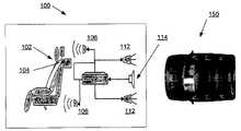
- FIG. 1there is depicted a representation of a lead vehicle 100 , which may be any type of motorized vehicle that accommodates a driver 102 or other occupants.
- the lead vehicle 100may be equipped with a passenger safety device 104 , such as any one or more of a seatbelt restraint system, an airbag system, a head support system or the like, as are commonly found in existing motorized vehicles.
- the lead vehiclemay also include one or more speakers 106 , also commonly found in existing motorized vehicles.
- a rear-end collision warning system conforming to the present disclosuremay be installed in the lead vehicle 100 , either at the time of manufacture or thereafter.
- the rear-end collision warning systemincludes a computer processing system 110 in electrical or wireless communication with one or more warning lights 112 , one or more external condition sensors 114 , and one or more speakers 106 .
- the computer processing system 110may be any type of microprocessor-controlled system that includes electronic memory for storing processing instructions and data that may be used to perform the calculations and determinations described herein.
- the microprocessor-controlled systemmay be existing systems, as are commonly found in existing motorized vehicles.
- the computer processing system 110may be separately installed in the lead vehicle 100 .
- the memorymay be any type of temporary or computer-readable memory device, including those using removable media.
- the warning lights 112receive signals from the computer processing system 110 to activate and warn the occupants of the lead vehicle 100 upon detection of a possible or potential rear-end collision.
- the warning lights 112may be existing lights of the lead vehicle 100 , such as dashboard lights in the field of view of the driver 102 or vehicle cabin lights, as are commonly found in existing motorized vehicles.
- the warning lights 112may be separately installed in the lead vehicle 100 .
- Such warning lights 112may be any type of illuminating device, such as incandescent or light emitting diode (LED) systems.
- a separate set of warning lights 112may receive signals from the computer processing system 110 to activate and warn a driver of an approaching second vehicle 150 upon detection by the lead vehicle 100 of a possible or potential rear-end collision.
- the computer processing system 110is connected to the existing taillight system of the lead vehicle 100 , so as to activate and flash the red brake lights, or other lights thereof.
- a separate array of rear-facing lightsmay be installed on or in the lead vehicle 100 .
- the separate arraymay include one or more monochromatic or multi-color lights. In the case of multi-color lights, such lights may include any combination of lights of various colors that can flash at varying rates and, preferably, may be addressed to flash according to various predetermined or selectable patterns.
- the colorsmay include primary colors (red, yellow blue, etc.) or any combination of the same (e.g. white). The colors may be selected from empirical and statistical information concerning colors that are more likely to attract a driver's attention.
- Any of the warning lights 112 as described abovemay be activated so as to flash when a second vehicle 150 approaches the lead vehicle 100 from the rear direction at an unsafe speed.
- the rate of flashingmay change as the time to collision changes, and/or may also be based on an estimated severity of the collision that ma be determined from various algorithms. For example, the rate of flashing may increase as a determined time to collision decreases or the estimated severity increases. However, any additional flashing scheme may be used, and may be determined from empirical and statistical information as to rates that are more likely to attract a driver's attention.
- Any of the warning lights 112 as described abovemay be activated so as to present various patterns when a second vehicle 150 approaches the lead vehicle 100 from the rear direction at an unsafe speed.
- the patternsmay change as the time to collision changes.
- Any type of pattern schememay be used, such as a numerical display indicating the distance or time-to-collision.
- the choice of symbolmay be determined from empirical and statistical information as to patterns that are more likely to attract a driver's attention.
- the one or more sensors 114 of the lead vehicle 100may be any type of sensor in communication with the computer processing system 110 to detect a second vehicle 150 that is approaching from the rear at an unsafe speed.
- a sensormay be a camera, such as a video camera, that can detect visual and or infrared (IR) light radiating from an approaching vehicle.
- IRinfrared
- Various types of existing camerasmay be used, including a traditional webcam sensor, such as the OMNIVISION OV518, or a 3-D camera sensor, such as the time-of-flight cameras from CANESTA CORP., or a realtime stereo system, such as those developed by TYZX CORP.
- the sensors 114may be one or more of any type of external condition sensor, such as a radar detection system, a lidar detection system, or an infrared detection system for detecting approaching vehicles, an accelerometer, speedometer, or any other existing sensors of the operation of the lead vehicle 100 , and may further include environmental sensors, such as temperature and road condition sensors, for detecting environmental conditions around the lead vehicle 100 .
- environmental sensorsmay be useful for allowing the computer processing system 110 to more accurately identify a possible rear-end collision in combination with the detected speed and distance of an approaching vehicle, as described in further detail later below. All the sensors described herein are readily available in various configurations from various existing manufacturers as well as in certain existing motorized vehicles.
- the speakers 106may be existing speakers of the lead vehicle 100 .
- additional speaker units of any available typemay be separately installed in the lead vehicle 100 and connected to the computer processing system 110 for annunciating audible collision warnings to the occupants of the lead vehicle 100 .
- the audible alerts transmittedmay be tonal and/or spoken warnings of various types.
- the audible warningsmay change as the time to collision changes, in any of a wide variety of manners that will be readily apparent to one of ordinary skill in the art.
- the computer processing system 110may be connected to various other devices, as described below with respect to the additional FIGS. herein.
- FIG. 2therein is depicted an exemplary process 200 performed by the computer processing system 110 for activating the warning devices (lights and/or speakers) described herein above.
- the process 200may be continuously run while the vehicle is in operation, or may, in various embodiments, be activated at critical times, such as when a vehicle is slowing down or at a stop.
- the process 200will be described with the embodiments where the one or more sensors 114 include a camera, however any number of alternate or additional types of sensors may be used with a suitably adapted process 200 , as will be readily apparent to one of ordinary skill in the art.
- the process 200commences when a sensor 114 , such as one or more cameras, transmits data, such as a visual or infrared image from a rear direction of the lead vehicle 100 , to the computer processing system 110 (step 202 ).
- the computer processing system 110stores the received data, with a time reference.
- the central processing system 110retrieves the last data received from the sensor 114 . Then, at step 206 , the computer processing system 110 compares the received data from step 202 , with previous data received from the sensor 114 retrieved in step 204 to determine whether there is a second vehicle 150 approaching from the rear.
- the current and previous imagesmay be analyzed using any of a wide variety of known computer vision algorithms, stored as processing instructions within the computer processing system 110 .
- Various computer vision algorithmsthat may be readily adapted by one of ordinary skill in the art for use herein may resemble those present in the OPENCV package from INTEL CORP.
- the computer processing system 110can compare image data to identify a threshold change therein that indicates the presence of a second vehicle 150 to the rear of the lead vehicle 100 . When there is no significant change in image data, the process 200 returns to step 202 above.
- the computer processing system 110may use a rate of change in image data, and in some embodiments, take into account the aspect of the image and positioning of the cameras, to determine a distance and a velocity, or relative velocity, of the second vehicle 150 .
- a time to collisionmay then be readily calculated based on the determined distance of the velocity of the second vehicle 150 .
- Such time to collision algorithmsmay also take into account whether the approaching vehicle 150 has sufficient braking capability to stop within the determined distance, as may be determined from sensor information of environmental conditions, programmed braking characteristics of various motorized vehicles, and/or data received from the vehicle 150 , as described in more detail later below
- the computer processing system 110determines whether a warning is to be provided to the driver 104 and/or the driver of the second vehicle 150 , based on the time to collision calculated in step 206 above. This may be readily accomplished, for example, by establishing a threshold value, or range of values, for the time to collision that will trigger a given type of alert. The predetermined range of values that determine whether and what type of alert should be activated may be based on empirical and statistical data concerning the usefulness of various alerts in preventing such collisions.
- the threshold valuesmay be programmed manually by a driver, installer or manufacturer using a suitable input/output device for communicating selectable values to the computer processing system 110 .
- the alertsmay comprise an activation of the speakers 106 and/or warning lights 112 , in any manner contemplated herein.
- the process 200returns to step 202 above.
- the process 200continues to step 210 , where an appropriate alert is generated for the occupants and, in various embodiments, the driver of the second vehicle 150 .
- the predetermined ranges of time to collisionmay be the same for warnings device addressing the occupants of the lead vehicle and warnings for the driver of the second vehicle 150 .
- the second drivermay be warned before or after the approaching driver, as may be determined necessary from the circumstances of the potential collision.
- the computer processing system 110may also activate one or more other devices as described herein, such as safety devices 104 of the lead vehicle 100 , as the time to collision becomes imminent.
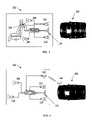
- FIG. 3shows an example in which the computer processing system 110 is operatively coupled to the safety devices 104 .
- the computer processing system 110may be in operative communication with an antenna 116 , as shown in FIG. 4 , and a transmitter, receiver and/or combination of the same (not shown).
- the computer processing system 110may include suitable programming instructions for using the antenna to transmit information to and/or receive information from a similarly or compatibly equipped second vehicle 150 having an antenna 166 and transmitter, receiver or combination thereof (not shown).
- the antennas 116 , 166may transmit and/or receive any one or more of RF, IR, optical or ultrasonic signals to communicate information.
- the computer processing system 110may transmit signals to the second vehicle 150 indicating a possible collision, based on the time to collision determined above and any threshold time values for triggering such an alert.
- a computer processing system 180 of the second vehicle 150may respond to such signals by activating at least one of: alerting devices 156 , 180 of the second vehicle 150 , a braking system 182 of the second vehicle 150 , and a safety device of the second vehicle 150 .
- FIG. 5further illustrates an example of such components in the second vehicle 150 .
- the brake information of the second vehicle 150can also be transmitted to the lead vehicle 100 to adjust its warning as well, and cancel them if appropriate, based on changes in the time to collision using the received data, thereby reducing incidences of false alarms.
- the second vehicle 150may also transmit its performance data, such as braking capabilities, model type, weight, current velocity and the like, which may be similarly used by the lead vehicle 100 to better identify a potential collision scenario and further reduce the false alarm rate of the disclosed collision warning system.
- performance datasuch as braking capabilities, model type, weight, current velocity and the like
- braking capabilitiesmay be similarly used by the lead vehicle 100 to better identify a potential collision scenario and further reduce the false alarm rate of the disclosed collision warning system.
- a truck and a sports carwill have different maneuvering characteristics. Their braking distances would also be different on wet or dry road surfaces.
- the systemcould modify the values in its time to collision/estimated severity algorithms to account for this data.
- the modelshould be adjusted to account for road surface conditions, such as temperature and roughness of road surface, precipitation conditions, current lateral acceleration (curves) and wind, all of which play known roles in determining the stopping and maneuvering capabilities of a motorized vehicle.
- the vehicle typemay be identified using various suitable computer vision algorithms alone, without the receipt of such data from the second vehicle 150 .
- Data on the environmental conditions and approaching vehiclecan also be received by the system by accessing relevant information from the Internet or other network via a wireless connection.
- FIG. 6shows an additional embodiment of a rear-end collision warning system according to the present disclosure in which other external condition sensors, such as lidar 118 and radar 120 can be used separately or together with the camera 114 to further improve the sensing quality of the lead vehicle 100 in various scenarios.
- the process 200may be modified to include the evaluation of such sensor data, which may improve the accuracy of velocity and distance from other sensors, such as cameras, or may be used when other sensor devices 114 become inoperative.
- FIG. 7shows an additional embodiment of a rear-end collision warning system in which one or more additional warning devices 122 can be provided to warn the driver of the second vehicle 150 .
- the one or more warning devices 122can include a visual digital sign 122 to display a textual warning to the second vehicle 150 . It may also display collision information such as the speed/distance of the following vehicle, the estimated time to collision and estimated severity of the collision. Such information may also be displayed to the driver 102 of the lead vehicle 100 , on a dashboard or other display.
- the angle of the arraymay be adjusted based on detected or received information for the second vehicle 150 , as well as the speed and distance of the second vehicle 150 , in order to stay viewable to the driver of the second vehicle 150 .
- FIG. 8shows an exemplary flowchart of a process 800 for persistently storing crash related data, include data from before the collision.
- the process 800may be independent of process 200 or incorporated in the process 200 , one example of which is demonstrated in FIGS. 2 and 8 , when a collision is imminent.
- the process 800commences when the computer processing system 110 receives sensor input from all the varieties of sensors 114 used. The computer processing system 110 then determines if recording is necessary based on whether the determined time to collision is within a range of predetermined or selectable values (step 804 ). If recording is not necessary, the process 800 terminates. If, however, the time to collision is within the range of values, the process 800 continues to step 806 wherein data from a predetermined range of time relevant to the collision is persistently stored. Simpler measures of collision risk, such as simple distance, may be used when the time to collision is not easily determined.
- a rear-end collision warning systemmay be adapted to detect vehicles 150 that are within a blind spot of the driver 102 on either side of the lead vehicle 100 .
- the central processing system 110may be programmed to transmit an audio or visual warning to the driver 102 .
- the audible warningmay be a sound broadcast from the speakers 106 resembling that of a passing car. The sound may, in various instances, be broadcast within the lead vehicle 100 by speakers 106 that are situated on the same side of the lead vehicle 100 as the detected second vehicle 150 .
- occupantsmay be warned using tactile warnings, in addition to visual and/or audio alerts.
- tactile warningsmay be provided by devices that generating a physical sensation that can be felt by the occupants, such as vibrating the seat of an occupant.
- Various additional tactile alertsmay be incorporated in the systems described herein.
Landscapes
- Engineering & Computer Science (AREA)
- Mechanical Engineering (AREA)
- Human Computer Interaction (AREA)
- Traffic Control Systems (AREA)
Abstract
Description
Claims (29)
Priority Applications (1)
| Application Number | Priority Date | Filing Date | Title |
|---|---|---|---|
| US11/320,267US7495550B2 (en) | 2005-12-28 | 2005-12-28 | Method and apparatus for rear-end collision warning and accident mitigation |
Applications Claiming Priority (1)
| Application Number | Priority Date | Filing Date | Title |
|---|---|---|---|
| US11/320,267US7495550B2 (en) | 2005-12-28 | 2005-12-28 | Method and apparatus for rear-end collision warning and accident mitigation |
Publications (2)
| Publication Number | Publication Date |
|---|---|
| US20070152803A1 US20070152803A1 (en) | 2007-07-05 |
| US7495550B2true US7495550B2 (en) | 2009-02-24 |
Family
ID=38223754
Family Applications (1)
| Application Number | Title | Priority Date | Filing Date |
|---|---|---|---|
| US11/320,267Active2026-03-12US7495550B2 (en) | 2005-12-28 | 2005-12-28 | Method and apparatus for rear-end collision warning and accident mitigation |
Country Status (1)
| Country | Link |
|---|---|
| US (1) | US7495550B2 (en) |
Cited By (32)
| Publication number | Priority date | Publication date | Assignee | Title |
|---|---|---|---|---|
| US20080309478A1 (en)* | 2007-06-15 | 2008-12-18 | Morales Charles J | Sequential brake light system |
| US20090045928A1 (en)* | 2007-08-16 | 2009-02-19 | Rao Manoharprasad K | System and method for combined blind spot detection and rear crossing path collision warning |
| US20090143986A1 (en)* | 2004-04-08 | 2009-06-04 | Mobileye Technologies Ltd | Collision Warning System |
| US20100302371A1 (en)* | 2009-05-27 | 2010-12-02 | Mark Abrams | Vehicle tailgating detection system |
| US20110013020A1 (en)* | 2008-04-21 | 2011-01-20 | Si-Rae Jo | Wireless transmitting and receiving apparatus for vehicle rear and side views independent of the vehicle's body and method thereof |
| US20110025848A1 (en)* | 2009-07-28 | 2011-02-03 | Hitachi, Ltd. | In-Vehicle Image Display Device |
| US20110313665A1 (en)* | 2009-03-04 | 2011-12-22 | Adc Automotive Distance Control Systems Gmbh | Method for Automatically Detecting a Driving Maneuver of a Motor Vehicle and a Driver Assistance System Comprising Said Method |
| US20120083983A1 (en)* | 2009-06-19 | 2012-04-05 | Bosch Corporation | Vehicular braking control device |
| US20130162447A1 (en)* | 2011-12-26 | 2013-06-27 | Electronics And Telecommunications Research Institute | System and method of changing vehicle color according to risk |
| CN103473952A (en)* | 2013-08-27 | 2013-12-25 | 曾灿民 | Relational vehicle-mounted precaution device |
| US20140184399A1 (en)* | 2012-12-31 | 2014-07-03 | Kia Motors Corporation | Rear collision warning alert system and method |
| US8855866B2 (en) | 2011-11-22 | 2014-10-07 | Continental Automotive Systems, Inc. | Rear end advanced collision technology |
| US20140309884A1 (en)* | 2013-04-10 | 2014-10-16 | Magna Electronics Inc. | Rear collision avoidance system for vehicle |
| US9251630B2 (en) | 2013-12-17 | 2016-02-02 | At&T Intellectual Property I, L.P. | Method, computer-readable storage device and apparatus for exchanging vehicle information |
| US9360332B2 (en) | 2012-08-27 | 2016-06-07 | Continental Teves Ag & Co. Ohg | Method for determining a course of a traffic lane for a vehicle |
| US9508201B2 (en) | 2015-01-09 | 2016-11-29 | International Business Machines Corporation | Identifying the origins of a vehicular impact and the selective exchange of data pertaining to the impact |
| US9829575B2 (en) | 2012-07-30 | 2017-11-28 | Conti Temic Microelectronic Gmbh | Method for representing a vehicle environment with position points |
| US9849852B1 (en)* | 2015-09-04 | 2017-12-26 | Waymo Llc | Intelligent deployment of safety mechanisms for autonomous vehicles |
| US9878658B2 (en) | 2013-03-15 | 2018-01-30 | Federal-Mogul Llc | Vehicle brake lighting |
| US9896092B2 (en) | 2012-04-26 | 2018-02-20 | Continental Teves Ag & Co. Ohg | Method for representing vehicle surroundings |
| US9959763B2 (en) | 2016-01-08 | 2018-05-01 | Ford Global Technologies, Llc | System and method for coordinating V2X and standard vehicles |
| CN108007436A (en)* | 2016-10-19 | 2018-05-08 | 德州仪器公司 | Collision time estimation in computer vision system |
| US10013881B2 (en) | 2016-01-08 | 2018-07-03 | Ford Global Technologies | System and method for virtual transformation of standard or non-connected vehicles |
| US10262539B2 (en) | 2016-12-15 | 2019-04-16 | Ford Global Technologies, Llc | Inter-vehicle warnings |
| US10336247B2 (en) | 2016-06-27 | 2019-07-02 | Deceleration Technologies, LLC | Apparatus and method for automatic application/deapplication of brake lights |
| WO2019148253A1 (en)* | 2018-02-05 | 2019-08-08 | Mark Peter Schwarz | A system and method of alerting road users to safe stopping distance |
| US10766408B2 (en) | 2016-02-29 | 2020-09-08 | Safely Brake, Inc. | Safety brake light module and method of engaging a safety brake light |
| US10773750B2 (en) | 2017-03-07 | 2020-09-15 | Continental Automotive Gmbh | Device and method for detecting manual guidance of a steering wheel |
| US11203318B2 (en) | 2018-06-18 | 2021-12-21 | Waymo Llc | Airbag extension system |
| US11358593B2 (en) | 2019-07-09 | 2022-06-14 | King Fahd University Of Petroleum And Minerals | Dual direction accident prevention and assistive braking system |
| US11620494B2 (en) | 2018-09-26 | 2023-04-04 | Allstate Insurance Company | Adaptable on-deployment learning platform for driver analysis output generation |
| US11794686B2 (en) | 2020-10-28 | 2023-10-24 | Toyota Motor Engineering & Manufacturing North America, Inc. | Deployable decoy vehicle system |
Families Citing this family (49)
| Publication number | Priority date | Publication date | Assignee | Title |
|---|---|---|---|---|
| US8301108B2 (en) | 2002-11-04 | 2012-10-30 | Naboulsi Mouhamad A | Safety control system for vehicles |
| US20070159311A1 (en)* | 2006-01-06 | 2007-07-12 | Scott Schober | Vehicle separation warning device |
| DE102007007507A1 (en)* | 2007-02-15 | 2008-08-21 | Robert Bosch Gmbh | Gap detector for the lane change of a motor vehicle on a multi-lane road |
| JP4412356B2 (en)* | 2007-06-13 | 2010-02-10 | 株式会社デンソー | Vehicle collision mitigation device |
| US20100066529A1 (en)* | 2007-10-09 | 2010-03-18 | Haines Walton P | Highly intelligent vehicle with brake light repeater |
| JP4458147B2 (en)* | 2007-10-26 | 2010-04-28 | トヨタ自動車株式会社 | Call device for vehicle, call system, center, call method |
| US8310353B2 (en)* | 2008-03-31 | 2012-11-13 | Honda Motor Co., Ltd. | Vehicle blind spot detection and indicator system |
| US8060280B2 (en)* | 2008-04-15 | 2011-11-15 | Autoliv Asp, Inc. | Vision system for deploying safety systems |
| US7898400B2 (en)* | 2008-04-15 | 2011-03-01 | Autoliv Asp, Inc. | Enhanced vision road detection system |
| US7545261B1 (en) | 2008-09-02 | 2009-06-09 | International Business Machines Corporation | Passive method and apparatus for alerting a driver of a vehicle of a potential collision condition |
| US20100157061A1 (en)* | 2008-12-24 | 2010-06-24 | Igor Katsman | Device and method for handheld device based vehicle monitoring and driver assistance |
| US8681216B2 (en)* | 2009-03-12 | 2014-03-25 | Hewlett-Packard Development Company, L.P. | Depth-sensing camera system |
| WO2011116375A1 (en)* | 2010-03-19 | 2011-09-22 | Northeastern University | Roaming mobile sensor platform for collecting geo-referenced data and creating thematic maps |
| DE102011077486B3 (en)* | 2011-06-14 | 2012-10-18 | Robert Bosch Gmbh | Device and method for triggering an occupant protection device, triggering system and vehicle |
| EP2798307A4 (en)* | 2011-12-29 | 2015-08-12 | Intel Corp | Navigation systems that enhance driver awareness |
| US9041552B2 (en)* | 2012-01-10 | 2015-05-26 | Xiao Lin Yu | Automobile blind spot detection system and method |
| EP2815383B1 (en)* | 2012-02-15 | 2017-08-16 | Mobileye Vision Technologies Ltd. | Time to collision using a camera |
| CN103903478A (en)* | 2012-12-29 | 2014-07-02 | 富泰华工业(深圳)有限公司 | Vehicle travelling early warning system |
| US9086948B1 (en) | 2013-03-13 | 2015-07-21 | Allstate Insurance Company | Telematics based on handset movement within a moving vehicle |
| US12008653B1 (en) | 2013-03-13 | 2024-06-11 | Arity International Limited | Telematics based on handset movement within a moving vehicle |
| US9260095B2 (en) | 2013-06-19 | 2016-02-16 | Magna Electronics Inc. | Vehicle vision system with collision mitigation |
| CN104417430A (en)* | 2013-08-29 | 2015-03-18 | 范钦 | Waistband type driving safety tactile system |
| US20150130607A1 (en)* | 2013-11-11 | 2015-05-14 | David MacArthur | Rear Brake Light System |
| US10692370B2 (en)* | 2014-03-03 | 2020-06-23 | Inrix, Inc. | Traffic obstruction detection |
| WO2016035215A1 (en)* | 2014-09-05 | 2016-03-10 | 横浜ゴム株式会社 | Collision avoidance system and collision avoidance method |
| WO2016035214A1 (en)* | 2014-09-05 | 2016-03-10 | 横浜ゴム株式会社 | Collision avoidance system and collision avoidance method |
| US9694747B2 (en)* | 2015-03-24 | 2017-07-04 | Verizon Patent And Licensing Inc. | Method and system for providing a collision alert |
| JP6090381B2 (en)* | 2015-07-29 | 2017-03-08 | 横浜ゴム株式会社 | Collision prevention system |
| EP3151216A1 (en)* | 2015-10-01 | 2017-04-05 | Volvo Car Corporation | Method for providing an alert to a driver and an alert system |
| US11066172B2 (en)* | 2015-10-15 | 2021-07-20 | The Boeing Company | Controlled energy absorption of seats for impact |
| US20170327037A1 (en)* | 2016-05-10 | 2017-11-16 | Ford Global Technologies, Llc | Adaptive rear view display |
| KR101850392B1 (en)* | 2016-05-12 | 2018-04-19 | 엘지전자 주식회사 | Control device mounted on vehicle and method for controlling the same |
| US10086830B2 (en)* | 2016-05-23 | 2018-10-02 | Ford Global Technologies, Llc | Accident attenuation systems and methods |
| US20170365105A1 (en)* | 2016-06-17 | 2017-12-21 | Ford Global Technologies, Llc | Method and apparatus for inter-vehicular safety awareness and alert |
| US10106075B2 (en)* | 2017-02-14 | 2018-10-23 | Ford Global Technologies, Llc | Vehicle hazard notification system |
| US11618380B2 (en) | 2017-06-12 | 2023-04-04 | Continental Automotive Gmbh | Rear pre-crash safety system |
| US10543837B2 (en)* | 2017-07-31 | 2020-01-28 | Microsoft Technology Licensing, Llc | Mitigating bodily injury in vehicle collisions by reducing the change in momentum resulting therefrom |
| GB2565353B (en)* | 2017-08-11 | 2020-02-26 | Westcotec Ltd | Improved road proximity warning systems |
| JP7193234B2 (en)* | 2018-02-06 | 2022-12-20 | 京セラ株式会社 | object detection device, object detection system |
| US10946979B2 (en) | 2018-04-13 | 2021-03-16 | The Boeing Company | Apparatus for controlling vehicle impact absorption systems and related methods |
| US11661055B2 (en)* | 2019-05-24 | 2023-05-30 | Preact Technologies, Inc. | Close-in collision detection combining high sample rate near-field sensors with advanced real-time parallel processing to accurately determine imminent threats and likelihood of a collision |
| US11117514B2 (en)* | 2019-06-07 | 2021-09-14 | Heath White | Motor vehicle visual and audio proximity warning system |
| US11878761B2 (en)* | 2019-12-06 | 2024-01-23 | Gekot, Inc. | Collision alert systems and methods for micromobility vehicles |
| US11802959B2 (en) | 2020-01-22 | 2023-10-31 | Preact Technologies, Inc. | Vehicle driver behavior data collection and reporting |
| JP7351269B2 (en)* | 2020-07-28 | 2023-09-27 | トヨタ自動車株式会社 | Brake control system, brake control method and program |
| KR20220152823A (en)* | 2021-05-10 | 2022-11-17 | 현대자동차주식회사 | Apparatus for recording drive video of vehicle and method thereof |
| CN113421438B (en)* | 2021-06-02 | 2022-07-26 | 上海大学 | A UAV-based traffic accident warning sign placement system and method |
| DE102021131436A1 (en) | 2021-11-30 | 2023-06-01 | Ford Global Technologies Llc | Rear-end collision avoidance system and method for rear-end collision avoidance |
| CN117261749A (en)* | 2022-06-13 | 2023-12-22 | 微软技术许可有限责任公司 | Brake reminding based on situation detection |
Citations (22)
| Publication number | Priority date | Publication date | Assignee | Title |
|---|---|---|---|---|
| US5786752A (en) | 1996-07-12 | 1998-07-28 | Bucalo; Louis R. | Emergency signal system for vehicles |
| US6012008A (en) | 1997-08-26 | 2000-01-04 | Scully; Robert L. | Method and apparatus for predicting a crash and reacting thereto |
| US6213512B1 (en) | 1998-12-14 | 2001-04-10 | Trw Inc. | Seat belt tightening apparatus |
| US6226389B1 (en)* | 1993-08-11 | 2001-05-01 | Jerome H. Lemelson | Motor vehicle warning and control system and method |
| US6225896B1 (en) | 2000-02-02 | 2001-05-01 | Ilan Sendowski | Panic stop, deceleration warning system |
| US6359552B1 (en) | 1998-06-17 | 2002-03-19 | Ut Automotive Dearborn, Inc | Fast braking warning system |
| US6405112B1 (en)* | 1998-02-09 | 2002-06-11 | Gary A. Rayner | Vehicle operator performance monitor with enhanced data retrieval capabilities |
| US20020171542A1 (en)* | 1999-11-15 | 2002-11-21 | Donnelly Corporation, A Corporation Of The State Of Michigan | Anti-collision safety system for vehicle |
| US20020198660A1 (en)* | 2001-06-26 | 2002-12-26 | Medius, Inc. | Method and apparatus for transferring information between vehicles |
| US6571161B2 (en) | 2001-01-22 | 2003-05-27 | General Motors Corporation | Pre-crash assessment of crash severity for road vehicles |
| US20030112132A1 (en)* | 2001-12-14 | 2003-06-19 | Koninklijke Philips Electronics N.V. | Driver's aid using image processing |
| US6609053B1 (en)* | 1995-06-07 | 2003-08-19 | Automotive Technologies International, Inc. | Method and apparatus for sensing a vehicle crash |
| US6746049B2 (en) | 2002-07-24 | 2004-06-08 | Visteon Global Technologies, Inc. | Adaptive seat belt tensioning system |
| US6765495B1 (en)* | 2000-06-07 | 2004-07-20 | Hrl Laboratories, Llc | Inter vehicle communication system |
| US20050128061A1 (en)* | 2003-12-10 | 2005-06-16 | Nissan Motor Co., Ltd. | Vehicular image display system and image display control method |
| US20050134441A1 (en)* | 2003-03-19 | 2005-06-23 | Eddie Somuah | Digital message display for vehicles |
| US20050134440A1 (en)* | 1997-10-22 | 2005-06-23 | Intelligent Technolgies Int'l, Inc. | Method and system for detecting objects external to a vehicle |
| US20050237172A1 (en)* | 2002-08-23 | 2005-10-27 | Boomershine Iii Walter M | Vehicle deceleration warning system |
| US20060071764A1 (en)* | 2004-09-24 | 2006-04-06 | Lynch William D | Merge Sensor Control System |
| US20060091653A1 (en)* | 2004-11-04 | 2006-05-04 | Autoliv Asp, Inc. | System for sensing impending collision and adjusting deployment of safety device |
| US20070040664A1 (en)* | 2005-08-19 | 2007-02-22 | Johnson Fred M | Collision deterrence apparatus and method therefor |
| US20070200322A1 (en)* | 2006-02-28 | 2007-08-30 | Toyoda Gosei Co., Ltd. | Knee protection air bag apparatus |
- 2005
- 2005-12-28USUS11/320,267patent/US7495550B2/enactiveActive
Patent Citations (22)
| Publication number | Priority date | Publication date | Assignee | Title |
|---|---|---|---|---|
| US6226389B1 (en)* | 1993-08-11 | 2001-05-01 | Jerome H. Lemelson | Motor vehicle warning and control system and method |
| US6609053B1 (en)* | 1995-06-07 | 2003-08-19 | Automotive Technologies International, Inc. | Method and apparatus for sensing a vehicle crash |
| US5786752A (en) | 1996-07-12 | 1998-07-28 | Bucalo; Louis R. | Emergency signal system for vehicles |
| US6012008A (en) | 1997-08-26 | 2000-01-04 | Scully; Robert L. | Method and apparatus for predicting a crash and reacting thereto |
| US20050134440A1 (en)* | 1997-10-22 | 2005-06-23 | Intelligent Technolgies Int'l, Inc. | Method and system for detecting objects external to a vehicle |
| US6405112B1 (en)* | 1998-02-09 | 2002-06-11 | Gary A. Rayner | Vehicle operator performance monitor with enhanced data retrieval capabilities |
| US6359552B1 (en) | 1998-06-17 | 2002-03-19 | Ut Automotive Dearborn, Inc | Fast braking warning system |
| US6213512B1 (en) | 1998-12-14 | 2001-04-10 | Trw Inc. | Seat belt tightening apparatus |
| US20020171542A1 (en)* | 1999-11-15 | 2002-11-21 | Donnelly Corporation, A Corporation Of The State Of Michigan | Anti-collision safety system for vehicle |
| US6225896B1 (en) | 2000-02-02 | 2001-05-01 | Ilan Sendowski | Panic stop, deceleration warning system |
| US6765495B1 (en)* | 2000-06-07 | 2004-07-20 | Hrl Laboratories, Llc | Inter vehicle communication system |
| US6571161B2 (en) | 2001-01-22 | 2003-05-27 | General Motors Corporation | Pre-crash assessment of crash severity for road vehicles |
| US20020198660A1 (en)* | 2001-06-26 | 2002-12-26 | Medius, Inc. | Method and apparatus for transferring information between vehicles |
| US20030112132A1 (en)* | 2001-12-14 | 2003-06-19 | Koninklijke Philips Electronics N.V. | Driver's aid using image processing |
| US6746049B2 (en) | 2002-07-24 | 2004-06-08 | Visteon Global Technologies, Inc. | Adaptive seat belt tensioning system |
| US20050237172A1 (en)* | 2002-08-23 | 2005-10-27 | Boomershine Iii Walter M | Vehicle deceleration warning system |
| US20050134441A1 (en)* | 2003-03-19 | 2005-06-23 | Eddie Somuah | Digital message display for vehicles |
| US20050128061A1 (en)* | 2003-12-10 | 2005-06-16 | Nissan Motor Co., Ltd. | Vehicular image display system and image display control method |
| US20060071764A1 (en)* | 2004-09-24 | 2006-04-06 | Lynch William D | Merge Sensor Control System |
| US20060091653A1 (en)* | 2004-11-04 | 2006-05-04 | Autoliv Asp, Inc. | System for sensing impending collision and adjusting deployment of safety device |
| US20070040664A1 (en)* | 2005-08-19 | 2007-02-22 | Johnson Fred M | Collision deterrence apparatus and method therefor |
| US20070200322A1 (en)* | 2006-02-28 | 2007-08-30 | Toyoda Gosei Co., Ltd. | Knee protection air bag apparatus |
Cited By (62)
| Publication number | Priority date | Publication date | Assignee | Title |
|---|---|---|---|---|
| US10579885B2 (en) | 2004-04-08 | 2020-03-03 | Mobileye Vision Technologies Ltd. | Collision warning system |
| US9168868B2 (en) | 2004-04-08 | 2015-10-27 | Mobileye Vision Technologies Ltd. | Collision Warning System |
| US20090143986A1 (en)* | 2004-04-08 | 2009-06-04 | Mobileye Technologies Ltd | Collision Warning System |
| US9096167B2 (en) | 2004-04-08 | 2015-08-04 | Mobileye Vision Technologies Ltd. | Collision warning system |
| US8879795B2 (en) | 2004-04-08 | 2014-11-04 | Mobileye Vision Technologies Ltd. | Collision warning system |
| US9916510B2 (en) | 2004-04-08 | 2018-03-13 | Mobileye Vision Technologies Ltd. | Collision warning system |
| US9656607B2 (en) | 2004-04-08 | 2017-05-23 | Mobileye Vision Technologies Ltd. | Collision warning system |
| US8082101B2 (en)* | 2004-04-08 | 2011-12-20 | Mobileye Technologies Ltd. | Collision warning system |
| US8861792B2 (en) | 2004-04-08 | 2014-10-14 | Mobileye Technologies Ltd. | Collison warning system |
| US7893823B2 (en)* | 2007-06-15 | 2011-02-22 | Morales Charles J | Sequential brake light system |
| US20080309478A1 (en)* | 2007-06-15 | 2008-12-18 | Morales Charles J | Sequential brake light system |
| US8552848B2 (en)* | 2007-08-16 | 2013-10-08 | Ford Global Technologies, Llc | System and method for combined blind spot detection and rear crossing path collision warning |
| US20090045928A1 (en)* | 2007-08-16 | 2009-02-19 | Rao Manoharprasad K | System and method for combined blind spot detection and rear crossing path collision warning |
| US20110013020A1 (en)* | 2008-04-21 | 2011-01-20 | Si-Rae Jo | Wireless transmitting and receiving apparatus for vehicle rear and side views independent of the vehicle's body and method thereof |
| US20110313665A1 (en)* | 2009-03-04 | 2011-12-22 | Adc Automotive Distance Control Systems Gmbh | Method for Automatically Detecting a Driving Maneuver of a Motor Vehicle and a Driver Assistance System Comprising Said Method |
| US20100302371A1 (en)* | 2009-05-27 | 2010-12-02 | Mark Abrams | Vehicle tailgating detection system |
| US20120083983A1 (en)* | 2009-06-19 | 2012-04-05 | Bosch Corporation | Vehicular braking control device |
| US8421863B2 (en)* | 2009-07-28 | 2013-04-16 | Hitachi, Ltd. | In-vehicle image display device |
| US20110025848A1 (en)* | 2009-07-28 | 2011-02-03 | Hitachi, Ltd. | In-Vehicle Image Display Device |
| US8855866B2 (en) | 2011-11-22 | 2014-10-07 | Continental Automotive Systems, Inc. | Rear end advanced collision technology |
| US20130162447A1 (en)* | 2011-12-26 | 2013-06-27 | Electronics And Telecommunications Research Institute | System and method of changing vehicle color according to risk |
| US8791811B2 (en)* | 2011-12-26 | 2014-07-29 | Electronics And Telecommunications Research Institute | System and method of changing vehicle color according to risk |
| US9896092B2 (en) | 2012-04-26 | 2018-02-20 | Continental Teves Ag & Co. Ohg | Method for representing vehicle surroundings |
| US9829575B2 (en) | 2012-07-30 | 2017-11-28 | Conti Temic Microelectronic Gmbh | Method for representing a vehicle environment with position points |
| US9360332B2 (en) | 2012-08-27 | 2016-06-07 | Continental Teves Ag & Co. Ohg | Method for determining a course of a traffic lane for a vehicle |
| US20140184399A1 (en)* | 2012-12-31 | 2014-07-03 | Kia Motors Corporation | Rear collision warning alert system and method |
| US9878658B2 (en) | 2013-03-15 | 2018-01-30 | Federal-Mogul Llc | Vehicle brake lighting |
| US9802609B2 (en) | 2013-04-10 | 2017-10-31 | Magna Electronics Inc. | Collision avoidance system for vehicle |
| US10207705B2 (en) | 2013-04-10 | 2019-02-19 | Magna Electronics Inc. | Collision avoidance system for vehicle |
| US9545921B2 (en) | 2013-04-10 | 2017-01-17 | Magna Electronics Inc. | Collision avoidance system for vehicle |
| US12077153B2 (en) | 2013-04-10 | 2024-09-03 | Magna Electronics Inc. | Vehicular control system with multiple exterior viewing cameras |
| US11718291B2 (en) | 2013-04-10 | 2023-08-08 | Magna Electronics Inc. | Vehicular collision avoidance system |
| US9327693B2 (en)* | 2013-04-10 | 2016-05-03 | Magna Electronics Inc. | Rear collision avoidance system for vehicle |
| US11485358B2 (en) | 2013-04-10 | 2022-11-01 | Magna Electronics Inc. | Vehicular collision avoidance system |
| US20140309884A1 (en)* | 2013-04-10 | 2014-10-16 | Magna Electronics Inc. | Rear collision avoidance system for vehicle |
| US10875527B2 (en) | 2013-04-10 | 2020-12-29 | Magna Electronics Inc. | Collision avoidance system for vehicle |
| CN103473952A (en)* | 2013-08-27 | 2013-12-25 | 曾灿民 | Relational vehicle-mounted precaution device |
| US10586405B2 (en) | 2013-12-17 | 2020-03-10 | At&T Intellectual Property I, L.P. | Method, computer-readable storage device and apparatus for exchanging vehicle information |
| US9697653B2 (en) | 2013-12-17 | 2017-07-04 | At&T Intellectual Property I, L.P. | Method, computer-readable storage device and apparatus for exchanging vehicle information |
| US9251630B2 (en) | 2013-12-17 | 2016-02-02 | At&T Intellectual Property I, L.P. | Method, computer-readable storage device and apparatus for exchanging vehicle information |
| US9508201B2 (en) | 2015-01-09 | 2016-11-29 | International Business Machines Corporation | Identifying the origins of a vehicular impact and the selective exchange of data pertaining to the impact |
| US9849852B1 (en)* | 2015-09-04 | 2017-12-26 | Waymo Llc | Intelligent deployment of safety mechanisms for autonomous vehicles |
| US9959763B2 (en) | 2016-01-08 | 2018-05-01 | Ford Global Technologies, Llc | System and method for coordinating V2X and standard vehicles |
| US10013881B2 (en) | 2016-01-08 | 2018-07-03 | Ford Global Technologies | System and method for virtual transformation of standard or non-connected vehicles |
| US10529235B2 (en) | 2016-01-08 | 2020-01-07 | Ford Global Technologies, Llc | System and method for virtual transformation of standard or non-connected vehicles |
| US10766408B2 (en) | 2016-02-29 | 2020-09-08 | Safely Brake, Inc. | Safety brake light module and method of engaging a safety brake light |
| US11305687B2 (en) | 2016-02-29 | 2022-04-19 | Safely Brake, Inc. | Safety brake light module and method of engaging a safety brake light |
| US10336247B2 (en) | 2016-06-27 | 2019-07-02 | Deceleration Technologies, LLC | Apparatus and method for automatic application/deapplication of brake lights |
| US10977502B2 (en) | 2016-10-19 | 2021-04-13 | Texas Instruments Incorporated | Estimation of time to collision in a computer vision system |
| US11615629B2 (en) | 2016-10-19 | 2023-03-28 | Texas Instruments Incorporated | Estimation of time to collision in a computer vision system |
| CN108007436A (en)* | 2016-10-19 | 2018-05-08 | 德州仪器公司 | Collision time estimation in computer vision system |
| US10262539B2 (en) | 2016-12-15 | 2019-04-16 | Ford Global Technologies, Llc | Inter-vehicle warnings |
| US10773750B2 (en) | 2017-03-07 | 2020-09-15 | Continental Automotive Gmbh | Device and method for detecting manual guidance of a steering wheel |
| WO2019148253A1 (en)* | 2018-02-05 | 2019-08-08 | Mark Peter Schwarz | A system and method of alerting road users to safe stopping distance |
| US11203318B2 (en) | 2018-06-18 | 2021-12-21 | Waymo Llc | Airbag extension system |
| US11608019B2 (en) | 2018-06-18 | 2023-03-21 | Waymo Llc | Airbag extension system |
| US12208762B2 (en) | 2018-06-18 | 2025-01-28 | Waymo Llc | Airbag extension system |
| US11878646B2 (en) | 2018-06-18 | 2024-01-23 | Waymo Llc | Airbag extension system |
| US12210955B2 (en) | 2018-09-26 | 2025-01-28 | Allstate Insurance Company | Adaptable on-deployment learning platform for driver analysis output generation |
| US11620494B2 (en) | 2018-09-26 | 2023-04-04 | Allstate Insurance Company | Adaptable on-deployment learning platform for driver analysis output generation |
| US11358593B2 (en) | 2019-07-09 | 2022-06-14 | King Fahd University Of Petroleum And Minerals | Dual direction accident prevention and assistive braking system |
| US11794686B2 (en) | 2020-10-28 | 2023-10-24 | Toyota Motor Engineering & Manufacturing North America, Inc. | Deployable decoy vehicle system |
Also Published As
| Publication number | Publication date |
|---|---|
| US20070152803A1 (en) | 2007-07-05 |
Similar Documents
| Publication | Publication Date | Title |
|---|---|---|
| US7495550B2 (en) | Method and apparatus for rear-end collision warning and accident mitigation | |
| US6831572B2 (en) | Rear collision warning system | |
| US10026319B2 (en) | Collision warning system | |
| US9511730B1 (en) | Collision warning system | |
| US10343601B2 (en) | Collision warning system | |
| US7991551B2 (en) | System and method for determining a collision status of a nearby vehicle | |
| US7158015B2 (en) | Vision-based method and system for automotive parking aid, reversing aid, and pre-collision sensing application | |
| US20130311075A1 (en) | Motorcycle and helmet providing advance driver assistance | |
| KR20200051085A (en) | Vehicle and control method for the same | |
| US20060162985A1 (en) | System for crash prediction and avoidance | |
| JP2001014596A (en) | Device for alarming vehicle collision | |
| US6784791B2 (en) | Potential collision detection and parking aid system | |
| JP2008524698A (en) | A device that monitors traffic signals and warns the driver | |
| US9262923B2 (en) | Blind spot detection system | |
| JP6941190B2 (en) | Rear pre-crash flashing hazard lamp system | |
| KR20220128507A (en) | Advanced Driver Assistance System, and Vehicle having the same | |
| US20130131928A1 (en) | Rear End Advanced Collision Technology | |
| US11872937B2 (en) | Severity prediction system and method | |
| JP2006315489A (en) | Vehicle surrounding alarm device | |
| CN215552860U (en) | Vehicles and their warning systems | |
| WO2019225371A1 (en) | Roadside device for road-to-vehicle communication, vehicle-side device, and road-to-vehicle communication system | |
| CN110549939A (en) | Vehicle alarm system | |
| US6864783B2 (en) | Potential collision detection and reversing aid system | |
| CN110040133A (en) | Anti-collision warning method and early warning system after a kind of vehicle | |
| JPH06119599A (en) | Vehicle running control device |
Legal Events
| Date | Code | Title | Description |
|---|---|---|---|
| AS | Assignment | Owner name:PALO ALTO RESEARCH CENTER INCORPORATED, CALIFORNIA Free format text:ASSIGNMENT OF ASSIGNORS INTEREST;ASSIGNORS:HUANG, QUINFENG;REICH, JIM;CHEUNG, PATRICK C.P.;AND OTHERS;REEL/FRAME:018238/0953;SIGNING DATES FROM 20060809 TO 20060810 | |
| AS | Assignment | Owner name:PALO ALTO RESEARCH CENTER INCORPORATED, CALIFORNIA Free format text:ASSIGNMENT OF ASSIGNORS INTEREST;ASSIGNORS:HUANG, QINGFENG;REICH, JAMES E.;CHEUNG, PATRICK C.P.;AND OTHERS;REEL/FRAME:020225/0843 Effective date:20071109 | |
| FEPP | Fee payment procedure | Free format text:PAYOR NUMBER ASSIGNED (ORIGINAL EVENT CODE: ASPN); ENTITY STATUS OF PATENT OWNER: LARGE ENTITY | |
| STCF | Information on status: patent grant | Free format text:PATENTED CASE | |
| FPAY | Fee payment | Year of fee payment:4 | |
| FPAY | Fee payment | Year of fee payment:8 | |
| MAFP | Maintenance fee payment | Free format text:PAYMENT OF MAINTENANCE FEE, 12TH YEAR, LARGE ENTITY (ORIGINAL EVENT CODE: M1553); ENTITY STATUS OF PATENT OWNER: LARGE ENTITY Year of fee payment:12 | |
| AS | Assignment | Owner name:XEROX CORPORATION, CONNECTICUT Free format text:ASSIGNMENT OF ASSIGNORS INTEREST;ASSIGNOR:PALO ALTO RESEARCH CENTER INCORPORATED;REEL/FRAME:064038/0001 Effective date:20230416 | |
| AS | Assignment | Owner name:CITIBANK, N.A., AS COLLATERAL AGENT, NEW YORK Free format text:SECURITY INTEREST;ASSIGNOR:XEROX CORPORATION;REEL/FRAME:064760/0389 Effective date:20230621 | |
| AS | Assignment | Owner name:XEROX CORPORATION, CONNECTICUT Free format text:CORRECTIVE ASSIGNMENT TO CORRECT THE REMOVAL OF US PATENTS 9356603, 10026651, 10626048 AND INCLUSION OF US PATENT 7167871 PREVIOUSLY RECORDED ON REEL 064038 FRAME 0001. ASSIGNOR(S) HEREBY CONFIRMS THE ASSIGNMENT;ASSIGNOR:PALO ALTO RESEARCH CENTER INCORPORATED;REEL/FRAME:064161/0001 Effective date:20230416 | |
| AS | Assignment | Owner name:JEFFERIES FINANCE LLC, AS COLLATERAL AGENT, NEW YORK Free format text:SECURITY INTEREST;ASSIGNOR:XEROX CORPORATION;REEL/FRAME:065628/0019 Effective date:20231117 | |
| AS | Assignment | Owner name:XEROX CORPORATION, CONNECTICUT Free format text:TERMINATION AND RELEASE OF SECURITY INTEREST IN PATENTS RECORDED AT RF 064760/0389;ASSIGNOR:CITIBANK, N.A., AS COLLATERAL AGENT;REEL/FRAME:068261/0001 Effective date:20240206 | |
| AS | Assignment | Owner name:U.S. BANK TRUST COMPANY, NATIONAL ASSOCIATION, AS COLLATERAL AGENT, CONNECTICUT Free format text:FIRST LIEN NOTES PATENT SECURITY AGREEMENT;ASSIGNOR:XEROX CORPORATION;REEL/FRAME:070824/0001 Effective date:20250411 | |
| AS | Assignment | Owner name:U.S. BANK TRUST COMPANY, NATIONAL ASSOCIATION, AS COLLATERAL AGENT, CONNECTICUT Free format text:SECOND LIEN NOTES PATENT SECURITY AGREEMENT;ASSIGNOR:XEROX CORPORATION;REEL/FRAME:071785/0550 Effective date:20250701 |